

BETTCHER INDUSTRIES 1850M2-S, 1850M2, 1880M2, 1000M2, 1300M2 Operating Instructions And Spare Parts Lists
...
BETTCHER
Industries, Inc.
750M2 (F/N *183000) Bone Trimmer
OPERATING INSTRUCTIONS AND SPARE PARTS LISTS
LARGE MODULAR SERIES II TOOLS
Models :
850M2 (F/N *183001) Defatting Machine
880M2-B&S (F/N *183002) Primal Fat Shaper
1850M2 (F/N *183003) Defatting Machine
1880M2 (F/N *183004) Primal Fat Shaper
1000M2 (F/N *183005) Defatting Machine
1300M2 (F/N *183006) Primal Fat Shaper
1400M2 (F/N *183007) Ham Finisher
1500M2 (F/N *183008) Skinning Machine
1930M2 (F/N *185000) Defatting Machine
1932M2 (F/N *185086) Defatting Machine
1933M2 (F/N *185001) Defatting Machine
1940M2 (F/N *185002) Defatting Machine
1942M2 (F/N *185087) Defatting Machine
1943M2 (F/N *185003) Slicing Machine
MANUAL #183130
Re-Issued : October 29, 2001
TMC #756

TECHNICAL BETTCHER LARGE MODULAR SERIES II WHIZARD
MANUAL INDUSTRIES, INC. REV. June 28, 2012
Information in this document is subject to change without notice.
No part of this document may be reproduced or transmitted in any form or any
means, electronic or mechanical, for any purpose, without the express written
permission of Bettcher Industries Inc.
Written permission to reproduce in whole or part is herewith granted to the legal
owners of the Whizard Trimmer with which these Operating Instructions have
been supplied.
Operating Instructions in other languages are available on request. Additional
copies of Operating Instructions are available by calling or writing the local
Representative or by contacting :
BETTCHER INDUSTRIES INC.
6801 State Route 60
Birmingham, Ohio 44889
U.S.A.
Telephone : 1-440-965-4422
(In The U.S.A.) : 1-800-321-8763
Fax : 1-440-965-4900
The Infomation Provided In These Operating Instructions Are
Important To Your Health, Comfort And Safety. For Safe
And Proper Operation, Read This Entire Manual
Before Using This Equipment.
Copyright 1999 By Bettcher Industries, Inc.
All Rights Reserved
Original Instructions
Page i

TECHNICAL BETTCHER LARGE MODULAR SERIES II WHIZARD
MANUAL INDUSTRIES, INC. REV. June 28, 2012
Table Of Contents
SECTION 1.0 Machine Specifications 1
SECTION 2.0 Designated Use 1
2.1 Warning 1
2.2 Recommended Operation 2
SECTION 3.0 Function 5
3.1 Machine Function Description 5
3.2 Safety Recommendations And Warnings 5
SECTION 4.0 Safety Features 7
SECTION 5.0 Ergonomics & Environment 8
5.1 Ergonomic Features 8
5.2 Noise And Vibration Levels 8
SECTION 6.0 Unpacking 9
6.1 Safety First 9
6.2 Included With Your Machine 9
SECTION 7.0 Installation 9
SECTION 8.0 Instructions For Operation 10
8.1 Optional Thumb Support And Handle Size Selection 10
8.2 Handle - Assembly & Adjustments 10
8.3 Proper Use/Operating Procedures 16
8.4 Fault Detection And Correction 22
Page ii

TECHNICAL BETTCHER LARGE MODULAR SERIES II WHIZARD
MANUAL INDUSTRIES, INC. REV. June 28, 2012
Table Of Contents
(Continued)
SECTION 9.0 Maintenance 24
9.1 Disassembly Of Handpiece 24
9.2 Daily Inspections & Maintenance 27
9.3 Blade Sharpening 34
9.4 Assembly 35
9.5 Preventative Maintenance 39
SECTION 10.0 Cleaning 40
10.1 Periodic Cleaning During Use 40
10.2 Daily Cleaning 40
10.3 Cleaning Solutions 40
SECTION 11.0 Spare Parts List 41
11.1 Head Assembly - 750M2 42
11.2 Head Assembly - 850M2 44
11.3 Head Assembly - 880M2-B 46
11.4 Head Assembly – 880M2-S 48
11.5 Head Assembly - 1850M2 50
11.6 Head Assembly – 1880M2 52
11.7 Head Assembly - 1000M2 54
11.8 Head Assembly - 1300M2 56
11.9 Head Assembly - 1400M2 58
11.10 Head Assembly - 1500M2 60
11.11 Head Assembly - 1930M2 62
11.12 Head Assembly - 1932M2 64
11.13 Head Assembly - 1933M2 66
11.14 Head Assembly - 1940M2 68
11.15 Head Assembly - 1942M2 70
11.16 Head Assembly - 1943M2 72
Page iii

TECHNICAL BETTCHER LARGE MODULAR SERIES II WHIZARD
MANUAL INDUSTRIES, INC. REV. June 28, 2012
Table Of Contents
(Continued)
11.17 Flex Shaft & Casing 74
11.18 Post Handle (Optional) 76
11.19 Optional Equipment Available 78
Lubrication and Lubrication Equipment 78
Optional Blades 78
Blade Sharpening and Steeling Equipment 78
Covers and Depth Gauges 78
Tools 79
Cleaning Equipment 79
Cleaning Solution 79
11.20 Handle Options 79
SECTION 12.0 About These Operating Instructions 80
12.1 Other Languages 80
12.2 Document Identification 80
12.3 Software & Duplication 80
SECTION 13.0 Contact Addresses & Phone 81
Page iv


TECHNICAL BETTCHER LARGE MODULAR SERIES II WHIZARD
MANUAL INDUSTRIES, INC. REV. June 28, 2012
SECTION 1.0 Machine Specifications
Bettcher Modular Series II Whizard tools are highly effective for use in the meat industry,
designed with the highest possible standards for safety, ergonomics and production. These
versatile machines, with their carefully engineered and durable cutting edge, bring uniformity and
consistent yield control to all operations. This Operating Instruction covers the following models:
Model Main Application
750M2 Bone Trimmer
850M2 Defatting Machine
880M2-B&S Primal Fat Shaper
1850M2 Defatting Machine
1880M2 Primal Fat Shaper
1000M2 Defatting Machine
1300M2 Primal Fat Shaper
1400M2 Ham Finisher
1500M2 Skinning Machine
1930M2 Defatting Machine
1932M2 Defatting Machine
1933M2 Defatting Machine
1940M2 Defatting Machine
1942M2 Defatting Machine
SECTION 2.0 Designated Use
2.1 Warning
1943M2 Slicing Machine
Modular Series II Whizard tools are used for removal of fat and tissue, the recovery of lean meat
from fat, and as a universal cutting tool in the meat industry. Any use in applications other than
those for which the Whizard trimmer was designed and built may result in serious injuries.
WARNING
THE MANUFACTURER ASSUMES NO LIABILITY FOR ANY
UNAUTHORIZED DESIGN CHANGES, MODIFICATIONS, OR USE OF
PARTS NOT SUPPLIED BY THE MANUFACTURER
OR
THE USE OF PARTS NOT DESIGNED FOR USE ON THAT SPECIFIC
MODEL, INCLUDING CHANGES IN OPERATING PROCEDURES MADE BY
THE OWNER OR ANY OF HIS PERSONNEL.
THE USE OF PARTS OTHER THAN THOSE LISTED IN THE PARTS LIST
FOR THE SPECIFIC MODEL MAY CAUSE BLADE LOCK-UP RESULTING
IN AN UNSAFE OPERATING CONDITION.
Page 1

TECHNICAL BETTCHER LARGE MODULAR SERIES II WHIZARD
MANUAL INDUSTRIES, INC. REV. June 28, 2012
2.2 Recommended Operations
Modular Series II Whizard tools are made for several recommended operations. Ensure that you
are using the correct tool for your specific application. The following recommendation list is not
intended to be a total and comprehensive listing, but is offered as a guide. Additional applications
are possible.
MODEL 750M2
PORK CUT PORK KILL FOAM INDUSTRY
Remove diaphragm lean
Removal of picnic hearts
Remove cheek meat
Remove blood clots from
jowls
Remove defects
Flash trimming
MODELS 850M2/1850M2
POULTRY BEEF PORK PROCESSING
Defatting turkey skins
Defatting turkey thighs
PORK KILL
Removing leaf lard
Recover lean from fat
Trim lean from rib caps
Trim beef tripe
External ham defatting
Internal ham defatting
Defat pork loins
Remove oyster meat
MODEL 880M2-B/1880M2 WITH ADJUSTABLE DEPTH GAUGE
BEEF BONING/FABRICATING
Removing Dirt and Hair
- Slaughter Floor
- Prior to Loading
- Upon Receiving
- Prior to Fabrication
Final Trim on Primal Fat Shaping
MODEL 880M2-S/1880M2 WITH ADJUSTABLE DEPTH GAUGE
HOG KILL/HOG CUT/HAM PROCESSING
Remove skin or hair patches
Trimming pork loins and Canadian backs
Internal and external defatting of hams
TOP ROUNDS/BOTTOM ROUNDS/BRISKETS/CUBE STEAK MATERIAL
Removing membranes and light fat covering
DEFATTING TURKEY THIGHS
Page 2

TECHNICAL BETTCHER LARGE MODULAR SERIES II WHIZARD
MANUAL INDUSTRIES, INC. REV. June 28, 2012
2.2 Recommended Operations (Continued)
MODEL 1000M2
HOG CUT
Defat hams, picnics and butts
Removing lean from:
- Picnic Face
- Clear Plates
Jowls shoulder end of belly
Belly (Wire muscle – Pickle pocket)
Plate Trim
- Fat Backs
- Bootjack
BEEF SLAUGHTER
Defatting hot beef externally & internally
Kidney fat, heart fat, pelvic fat & cod fat
MODEL 1300M2
BEEF KILL
Pizzle cord removal
Removing external fat
BEEF BONING/
FABRICATION
Primal Fat Shaping:
- Strips
- Sirloin Butts
HAM BONING
External defat of hams
External defat of pork shoulders
- Ribs
Defat navels (Pastrami)
MODEL 1400M2 WITH ADJUSTABLE DEPTH GAUGE
PORK PROCESSING
Defatting:
- Whole Hams
- Shoulders
- Canadian Backs
Removing Beater Marks
Scraping Leaf Lard
BEEF PROCESSING
Carcass hair & dirt removal
Defatting:
- New York strips & sirloin butts
- Rounds and ribeyes
MODEL 1500M2 WITH ADJUSTABLE DEPTH GAUGE
PORK PROCESSING
Removing skin patches from bellies
Defatting:
- Whole Hams
- Pork Loins
BEEF SLAUGHTER
Defatting hot beef externally
Hair and dirt removal
Page 3

TECHNICAL BETTCHER LARGE MODULAR SERIES II WHIZARD
MANUAL INDUSTRIES, INC. REV. June 28, 2012
2.2 Recommended Operations (Continued)
MODEL 1930M2
BEEF SLAUGHTER
Defatting Hot Beef
MODEL 1932M2 WITH ADJUSTABLE DEPTH GAUGE
BEEF PROCESSING
Defatting Strips
MODEL 1933M2 WITH ADJUSTABLE DISC GAUGE
BEEF PROCESSING
Defatting Strips
MODEL 1940M2
BEEF SLAUGHTER
Defatting Hot Beef
MODEL 1942M2 WITH ADJUSTABLE DEPTH GAUGE
BEEF PROCESSING
Defatting Strips
MODEL 1943M2 WITH ADJUSTABLE DISC GAUGE
BEEF PROCESSING SALMON PROCESSING
Defatting Strips Slicing
Page 4

TECHNICAL BETTCHER LARGE MODULAR SERIES II WHIZARD
MANUAL INDUSTRIES, INC. REV. June 28, 2012
SECTION 3.0 Function
3.1 Machine Functions
Modular Series II Whizard tools are durable and efficient, promoting higher yields for
meat and poultry trimming. The Modular Series II Whizard tools are superbly designed
for ease of handling while reducing operator fatigue. Modular Series II Whizard tool
blades maintain accurate and continued sharpness.
A vertically hung motor drives a flexible shaft. The flexible shaft drives a rotating blade in
the handpiece via a gear and pinion. The force to cut through meat and fat is now provided
by the drive motor and no longer by the worker. Forces applied by the worker are greatly
reduced and limited to guiding the rotating knife blade.
3.2 Safety Recommendations And Warnings
WARNING
SHARP BLADES MAY CAUSE CUT INJURY!
Modular Series II Whizard tools have been designed to obtain the highest possible
degree of safety. The Trimmer contains sharp knife blades. Handle this equipment with
caution as you would with any sharp object. In particular, read and apply the following
safety recommendations :
WARNING
SHARP BLADES MAY CAUSE CUT INJURY!
PROPER PROTECTION OF HANDS, A PROTECTIVE
FOR
GLOVE SHOULD BE USED WHEN OPERATING THIS
EQUIPMENT AND DURING THE HANDLING OF BLADES.
METAL MESH GLOVES ARE RECOMMENDED
THE FREE HAND.
FOR
Page 5

TECHNICAL BETTCHER LARGE MODULAR SERIES II WHIZARD
MANUAL INDUSTRIES, INC. REV. June 28, 2012
3.2 Safety Recommendations And Warnings (Continued)
WARNING
KEEP HANDS AWAY FROM MOVING BLADE!
WARNING
ALWAYS TURN OFF THE MOTOR AND PLACE THE HANDPIECE IN THE
HANGER BRACKET. NEVER LAY THE HANDPIECE DOWN ON THE
WORKSTATION OR LET IT HANG FREE BY THE FLEX SHAFT CASING.
NEVER PLACE THE HANDPIECE IN THE HANGER WHILE THE BLADE IS
STILL REVOLVING!
WARNING
ALWAYS DISCONNECT THE POWER AND REMOVE THE TOOL FROM
THE FLEX SHAFT CASING PRIOR TO SERVICING!
WARNING
IF AT ANY TIME THIS MACHINE DOES NOT APPEAR TO OPERATE
NORMALLY OR EXHIBITS A MARKED CHANGE IN PERFORMANCE, IT
SHOULD BE IMMEDIATELY SHUT DOWN, UNPLUGGED, AND TAGGED AS
"UNSAFE" UNTIL SUCH TIME AS PROPER REPAIRS ARE MADE AND THE
MACHINE AGAIN OPERATES NORMALLY.
WARNING
AFTER SERVICE OF THE UNIT, ALWAYS CHECK TO ENSURE THAT THE
BLADE IS FREE TO ROTATE IN THE MACHINE PRIOR TO STARTING. IF
THE BLADE DOES NOT ROTATE FREELY, IT MAY CAUSE THE
HANDPIECE TO ROTATE IN THE HAND.
Page 6

TECHNICAL BETTCHER LARGE MODULAR SERIES II WHIZARD
MANUAL INDUSTRIES, INC. REV. June 28, 2012
3.2 Safety Recommendations And Warnings (Continued)
WARNING
LENGTHY OR REPEATED USE OF VARIOUS POWER TOOLS VIBRATING
EXCESSIVELY IS SUSPECTED OF CONTRIBUTING TO CERTAIN HAND,
WRIST OR FOREARM DISORDERS IN SUSCEPTIBLE INDIVIDUALS. IF
EXCESSIVE VIBRATION OCCURS, IT IS AN INDICATION THAT THERE ARE
WORN PARTS THAT NEED REPLACEMENT.
WARNING
IF YOUR WHIZARD TRIMMER DEVELOPS UNUSUAL VIBRATION, DO NOT
CONTINUE TO USE IT WITHOUT FIRST UNDERTAKING CORRECTIVE
ACTION AS OUTLINED IN THE TROUBLESHOOTING GUIDE IN THIS
OPERATING INSTRUCTION.
WARNING
AVOID USE OF THIS MACHINE IN STANDING WATER.
WARNING
USE ONLY REPLACEMENT PARTS MANUFACTURED BY BETTCHER
INDUSTRIES, INC. USE OF SUBSTITUTE PARTS WILL VOID THE
WARRANTY AND MAY CAUSE INJURY TO OPERATORS AND DAMAGE TO
EQUIPMENT.
SECTION 4.0 Safety Features
All Modular Series II Whizard tools have been designed for use with an optional
Disconnect which will stop blade rotation when the trigger/lever is released. This
trigger/lever has been designed in such a way that minimal grip force is required for
operation, using three fingers.
Page 7

TECHNICAL BETTCHER LARGE MODULAR SERIES II WHIZARD
MANUAL INDUSTRIES, INC. REV. June 28, 2012
SECTION 5.0 Ergonomics And Environment
5.1 Ergonomic Features
Handles – X-Small, Small, Medium, and Large Handle sizes are available to help improve
the operator’s grip and comfort. Fitting the correct size handle to the worker's hand is a
very important step. The Modular Series II Whizard tools have been manufactured in
both right and left handed configurations. All handles are also available without flanges, to
allow for more freedom of movement where space is limited.
Optional Thumb Support - An adjustable Thumb Support is available to ensure a proper
and comfortable fit while providing added control and stability of the tool during use.
Whizard Hand Strap - This Strap has been designed to allow the user to relax the fingers
between work cycles while maintaining control of the Trimmer.
NOTE: The Whizard® handstrap can not be
used with the flangeless handles.
5.2 Noise And Vibration Levels
The force to cut through meat and fats is now provided by the drive motor and no longer
by the worker. Forces applied by the worker are greatly reduced and limited to guiding the
rotating knife blade.
The noise emission value is less than 70 dB(A)
Vibration of the handpiece is less than 1 m/sec2
No negative side effects have been reported.
Page 8

TECHNICAL BETTCHER LARGE MODULAR SERIES II WHIZARD
MANUAL INDUSTRIES, INC. REV. June 28, 2012
SECTION 6.0 Unpacking
6.1 Safety First
WARNING
SHARP BLADES MAY CAUSE CUT INJURY!
UNPACK THE WHIZARD TRIMMER CAREFULLY.
6.2 Included With Your Machine
The following parts are included with each Modular Series II Whizard tool. Please
check when unpacking and advise your local Bettcher Industries representative if the
delivery is incomplete.
Part Number Description Qty.
100642 Whizard® Special Steel 1
100660 Special Stone 1
113415 Grease Gun (for 8 oz. tube of Whizard® Grease) 1
100608 8 oz. Tube Whizard® Grease 1
143631 14 oz. Cartridge of Special Whizard® Grease 1
183130 Operating Instructions and Spare Parts List 1
SECTION 7.0 Installation
The work station for each operator should be designed so that the operator's movements in
performing the job are natural and easy. A sideways sweeping motion with the Modular
Series II Whizard tool is preferable to a reaching motion. Long reaching motions and
high muscle strain should be avoided if possible. Also, a proper working height is needed
to avoid excessive shoulder and back exertion. Refer to the Whizard Motor Manual for
instructions on the proper placement and installation of the motor.
Page 9

TECHNICAL BETTCHER LARGE MODULAR SERIES II WHIZARD
MANUAL INDUSTRIES, INC. REV. June 28, 2012
SECTION 8.0 Instruction For Operation
8.1 Optional Thumb Support And Handle Size Selection
Your Modular Series II Whizard® tool has been supplied with a spacer ring and an optional thumb
support. If using the optional thumb support, the operator’s thumb should be fully supported and
rest comfortably in the support. The thumb support has been optimized to fit most hands
comfortably.
Fitting the correct size handle to the grip of an operator’s hand is a very important step when
trying to reduce risks associated with cumulative trauma disorders. The Trimmers are
available in right and left handed configurations. Once it has been determined that an operator
is right or left handed and the appropriate model of Trimmer has been selected, choosing the
proper handle size can be accomplished in the following manner. The handles have been
color-coded for size as follows:
Tan
Turquoise
Grey
Blue
Green
Here is a very simple procedure to determine correct handle size:
STEP 1 - Assemble four (4) knives each with a different size handle. (See Section 8.2 for
complete assembly instructions).
STEP 2 - Allow the user to hold the knife and apply the grip pressure normally used during
the job operation.
If the operator normally wears a glove, this process
should be done with the glove(s) used in normal operation.
We do not recommend the use of Nitrile gloves in direct
contact with the Whizard® handles because
the gloves may become slippery.
The operator should choose the handle that is most comfortable. Allow the operator to work
with this handle on a tool for several days. If the operator is not comfortable with the handle
selection, try a different size.
XX-Small
X-Small
Small
Medium
Large
NOTE
Page 10

TECHNICAL BETTCHER LARGE MODULAR SERIES II WHIZARD
MANUAL INDUSTRIES, INC. REV. June 28, 2012
8.1 Optional Thumb Support And Handle Size Selection (Continued)
Short
Groove
8.2 Handle - Assembly And Adjustment
The Modular Series II Whizard tools have been designed to allow the head of the tool to
be rotated relative to the handle. In this way, the tool can be adjusted to position the blade
properly to the product while the handle can be set to allow the operator to have a
comfortable position for the wrist.
The position which is selected will vary based on the individual work station, product, and
operator. To determine the proper position, it will be necessary to observe the operator
while trying various positions. Select the position in which the operator's wrist appears to
maintain the most neutral position and which is comfortable to the operator.
Note that left handed heads are available for left handed users. Do not assign a knife
designed for a right handed person to a left handed user. Possible exposure to increased
muscle stress may result.
Page 11

TECHNICAL BETTCHER LARGE MODULAR SERIES II WHIZARD
MANUAL INDUSTRIES, INC. REV. June 28, 2012
8.2 Handle - Assembly And Adjustment (Continued)
WARNING
SHARP BLADES MAY CAUSE CUT INJURY!
STEP 1
Pick up the Whizard Trimmer
Pick up a spacer ring or optional thumb support
If the optional thumb support is used, align the
thumb support tab with one of the notches
on the underside of the frame
The optional thumb support should be located
on the opposite side of the grease cup
Frame
Notches
STEP 2
While holding the Trimmer, pick up a handle and align the four (4) handle tabs with the four
notches located on the threaded portion of the frame tube
Firmly push the handle towards the bottom of the spacer ring or optional thumb support, and
align the handle tabs with the notches on the front of the tube as shown
For the initial adjustment position, the short groove on the handle should be on top, as shown.
STEP 3
Screw on the handle retaining knob.
Tighten firmly, but take care not to overtighten or the handle will be damaged.
Short Groove
Optional
Thumb Support
Handle
Tabs (4)
Handle
Retaining
Knob
Frame Tube Threads
Frame Notches
Page 12

TECHNICAL BETTCHER LARGE MODULAR SERIES II WHIZARD
MANUAL INDUSTRIES, INC. REV. June 28, 2012
8.2 Handle - Assembly And Adjustment (Continued)
The Whizard Hand Strap has been designed to allow the user to relax the fingers of the
hand between work cycles while maintaining control of the Trimmer.
NOTE: The Whizard® handstrap can not be
used with the flangeless handles.
Installation Of The Hand Strap
Remove the grease cup from the tool.
Push the grease cup thread through the round grommet end of the strap. Be sure that
the ribbed surface of the strap is on top as shown.
Reinstall the grease cup.
Weave the end of the strap down and back up through the slots in the flange of the
handle. The strap may be pulled through the slots to adjust for size.
An optional secondary strap has been provided with your Modular Series II Whizard
tool. To install the secondary strap :
Weave the secondary strap end through the opposite handle slots similar to the method
used to install the primary hand strap.
Bring the loose end of the strap across the tool and snap closed.
Primary
Hand
Strap
Optional
Secondary
Hand Strap
Page 13

TECHNICAL BETTCHER LARGE MODULAR SERIES II WHIZARD
MANUAL INDUSTRIES, INC. REV. June 28, 2012
8.2 Handle - Assembly And Adjustment (Continued)
The Disconnect Casing
Connect the casing to the Bettcher Industries motor as described in the motor manual.
Hold the trimmer in the hand you will use in operation, and with the other hand, grasp the
casing and push it into the end of the tool through the handle retaining knob.
Push the casing in until the latch catches the casing.
The disconnect lever rotates freely around the handle.
Align the disconnect lever in the notched-out area of the handle. Slightly open the fingers on
the hand holding the trimmer. Push the casing inward and hold the lever down in the handle
groove with the normal operating hand.
Check to see that the lever is seated completely flat within the groove.
Release the lever and the casing should pop out and stop the blade from turning. The motor
will continue to operate.
Handle Retaining Knob
Handle Groove
Disconnect Lever
NEVER
ALWAYS
WARNING
SHARP BLADES MAY CAUSE CUT INJURY!
LAY THE HANDPIECE DOWN ON THE WORK STATION OR LET IT HANG BY THE
FLEX SHAFT CASING.
TURN OFF AND PLACE THE HANDPIECE IN THE HANGER BRACKET.
NEVER
PLACE THE HANDPIECE IN THE HANGER WHILE THE BLADE
IS STILL REVOLVING!
Page 14

TECHNICAL BETTCHER LARGE MODULAR SERIES II WHIZARD
MANUAL INDUSTRIES, INC. REV. June 28, 2012
8.2 Handle - Assembly And Adjustment (Continued)
WARNING
SHARP BLADES MAY CAUSE CUT INJURY!
WHILE WEARING A PROTECTIVE GLOVE, ALWAYS CHECK TO ENSURE
THAT THE BLADE IS FREE TO ROTATE IN THE MACHINE PRIOR TO
STARTING. IF THE BLADE DOES NOT ROTATE, IT MAY CAUSE THE
HANDPIECE TO ROTATE IN THE HAND.
With the handpiece held in your operating hand, stand at your normal work position and
move your hand and the handpiece over your normal work area to check that there are no
binds or sharp bends in the flex shaft and casing assembly.
With your other hand, turn on the motor switch. While the blade is rotating, press the
rubber cap of the grease cup on the handpiece with your thumb. Press only until a light
coating of lubricant appears on the blade in the gear tooth area.
During daily use, the grease cup rubber cap should be depressed every 30 minutes. Refill
when empty.
WHIZARD SPECIAL GREASE COMPLIES WITH
USDA H1 STANDARDS FOR USE IN FEDERALLY
INSPECTED MEAT AND POULTRY PLANTS AND IS
AUTHORIZED BY AGRICULTURE AND AGRI-FOOD CANADA
FOR USE IN FOOD PLANTS.
DO NOT USE A SUBSTITUTE TYPE LUBRICANT.
USE OF SUBSTITUTE LUBRICANTS COULD
RESULT IN DAMAGE TO THE UNIT.
Prior to placing the tool in operation, refer to the guidelines for tool adjustment and handle
size selection. It is critical to use the proper size handle and that the tool be properly
adjusted in order to gain the full benefit of the
Modular Series II Whizard tool design
concept.
You are now ready to put the Modular Series II Whizard® tool into operation.
Page 15

TECHNICAL BETTCHER LARGE MODULAR SERIES II WHIZARD
MANUAL INDUSTRIES, INC. REV. June 28, 2012
8.3 Operating Procedure
WARNING
SHARP BLADES MAY CAUSE CUT INJURY!
NEVER
ALWAYS
Always hold the handpiece of the Modular Series II Whizard® tool with your thumb
extended. Let the handpiece rest naturally in the palm of the hand in a relaxed manner.
Each person should be allowed to hold the handpiece in a position that is most comfortable
to them.
The most-used motion is a long sweeping or gliding stroke across the trimming surface.
Hold the blade surface as flat to the trim surface as possible. A scooping action, such as
dipping ice cream, should be used around the vertebra.
On flat bones, such as backbones or blades, use a long, quick gliding stroke.
During the cutting operation do not try to pull the blade out of a cut. Let the blade do the
work as you would any other cutting tool. Finding the proper angle for Whizard
trimming will become easy after experience and use of the tool.
As with any meat cutting tool, your speed and efficiency is only as good as the blade
sharpness.
In order to achieve maximum unit and operator efficiency, it is recommended that sharp
blades be installed at each shift break. For this reason, it is suggested that extra blades be
kept on hand. For example, if 4 units are being used and there are 3 shift breaks, 16 blades
would be required. This would provide a sharp blade for start up and one for each break.
When following this procedure, steeling of the blade is virtually eliminated, and blades
need only be sharpened once a day with the use of a Whizard Model 210 Universal Blade
Sharpener, Bettcher® AutoEdge, or by hand stoning.
If blades are not changed at each shift break, it may be required to steel the blade.
HOLD THE PRODUCT BEING TRIMMED IN YOUR HAND.
LAY THE PRODUCT FLAT ON THE WORK SURFACE.
Page 16

TECHNICAL BETTCHER LARGE MODULAR SERIES II WHIZARD
MANUAL INDUSTRIES, INC. REV. June 28, 2012
8.3 Operating Procedure (Continued)
WARNING
SHARP BLADES MAY CAUSE CUT INJURY!
PROPER PROTECTION OF HANDS, A PROTECTIVE GLOVE
FOR
SHOULD BE USED WHEN OPERATING THIS EQUIPMENT AND
DURING THE HANDLING OF BLADES.
ALWAYS
DISCONNECT THE POWER AND REMOVE THE TOOL FROM
THE FLEX SHAFT CASING PRIOR TO SERVICING.
For Models 880M2-S&B,1880M2, 1400M2, 1500M2, 1932M2 and 1942M2 Only :
These tools are equipped with an adjustable Depth Gauge for setting a controlled product trim
thickness. The Depth Gauge can be adjusted for cuts up to ¼” thick. A Depth Gauge Setting
Device is also available. To adjust depth :
Hold the handpiece with the blade facing downward.
Loosen the attachment screws at the base of the plastic depth gauge.
Adjust the gauge setting by sliding it up or down to the desired height.
Retighten the attachment screws.
Depth Gauge Adjustment Range :
Slide to Adjust
Moving Up = Thicker Cut
Moving Down = Thinner Cut
Attachment
Screws
Model 880M2-B Model 1400M2
Page 17

TECHNICAL BETTCHER LARGE MODULAR SERIES II WHIZARD
MANUAL INDUSTRIES, INC. REV. June 28, 2012
8.3 Operating Procedure (Continued)
Optional Adjustable Fat (F) and Skinner (S) Disc Gauges
(850M2, 1000M2, 1300M2, 1933M2 and 1943M2):
Hold the handpiece with the blade facing
downward.
Adjustments – Turn the adjustment knob
clockwise for a thicker cut, or counterclockwise
Adjustment
Blade
Disc
Knob
Attachment
Screws (2)
for a thinner cut. Take care not to turn too far
as the depth control hub may disengage from
the shaft.
Model 1000M2-S
WARNING
SHARP BLADES MAY CAUSE CUT INJURY!
OR PROPER PROTECTION OF HANDS, A PROTECTIVE GLOVE SHOULD
F
BE USED WHEN OPERATING THIS EQUIPMENT AND DURING THE
HANDLING OF BLADES.
LWAYS DISCONNECT THE POWER AND REMOVE THE TOOL FROM THE
A
FLEX SHAFT CASING PRIOR TO SERVICING.
Steeling For All Models Except 750M2:
Use the Whizard Special Steel anytime you feel the edge of the blade needs to be raised for
better cutting action.
Use the Whizard Special Steel against the flat ground surface on the outside surface of the
blade. Be sure to hold the "steel" flat and across the centerline of the blade to prevent "rounding
off" or rolling of the edge.
The inside edge of the blade should be steeled only with the Special Steeling Device mounted on
the inside diameter of the blade housing. This is accomplished as follows :
Page 18

TECHNICAL BETTCHER LARGE MODULAR SERIES II WHIZARD
MANUAL INDUSTRIES, INC. REV. June 28, 2012
8.3 Operating Procedure (Continued)
Hold the Whizard Special Steel on the bottom edge of the blade and the handpiece in your
normal operating hand with the blade down, or away from you.
With your thumb, lightly push down on the push button of the steeling device. DO NOT hold
the steeling device against the rotating blade steadily, but rather lightly contact the blade edge.
Whizard
Special Steel
Push Button
Special Steeling
Device
While steeling the inside edge,
use the Whizard Special Steel
to steel the bottom edge.
Models 850M2/880M2-S&B/
1850M2 and 1880M2
Whizard
Special
Steel
Whizard
Special Steel &
Push Button
Models 1000M2/1300M2/1400M2/1500M2
Replace or sharpen the blade (see Section 9.3 for complete instructions) if this procedure does not
improve the cutting action.
Steeling For Models 750M2 Only :
Use the Whizard Special Steel any time you feel the blade needs to be raised for better cutting
action. Be sure to hold the steel at the actual angle of the blade edge. Running the steel at an angle
greater than the factory ground angle will round over the edge and make resharpening more
difficult.
Cross-Section View Of Steeling
Inside Blade Edge
Cross-Section View Of Steeling
Outside Blade Edge
Whizard Special Steel
Use the steel lightly and always make the last pass of the steel on the blade on the inside surface of
the blade.
Page 19

TECHNICAL BETTCHER LARGE MODULAR SERIES II WHIZARD
MANUAL INDUSTRIES, INC. REV. June 28, 2012
8.3 Operating Procedure (Continued)
WARNING
SHARP BLADES MAY CAUSE CUT INJURY!
PROPER PROTECTION OF HANDS, A PROTECTIVE
FOR
GLOVE SHOULD BE USED WHEN OPERATING THIS
EQUIPMENT AND DURING THE HANDLING OF BLADES.
ALWAYS
DISCONNECT THE POWER AND REMOVE THE TOOL
FROM THE FLEX SHAFT CASING PRIOR TO SERVICING.
The Modular Series II Whizard tools have been designed in such a way as to allow the blades to
be quickly removed and reinstalled.
Blade Changing
Hold the tool in your hand.
Loosen only the left cover retaining screw (Item #1)
With a screwdriver held in the opposite hand, insert the screwdriver in the housing slot (Item
#2). Note: The 1000M2-1500M2 tools have two slots in the housing. Using the frame as the
support point (Item #3), spread open the housing. The blade should fall out.
NOTE:
A slight tension on the left cover screw will allow
To Re-Install The Blade :
Turn the tool over so the blade side is up.
Spread open the blade housing with a screwdriver.
Insert a new blade in the housing.
Loosen the left cover screw so the housing will close.
Adjust the housing for proper running clearance. The blade should turn freely with a slight
side-to-side motion. This leaves room for the grease.
B
E CERTAIN THAT THE BLADE IS FREE TO ROTATE IN THE HOUSING. IF THE BLADE DOES NOT
TURN FREELY
Tighten the left cover screw to 35 in-lb. (4 N-m). Use of the Bettcher torque wrench kit is
recommended.
Re-check the running clearance.
, IT MAY CAUSE THE TOOL TO ROTATE IN THE HAND.
the blade housing to stay open on its own.
NOTE:
Leave a slight tension on the left cover screw
so the blade housing will stay open on its own.
Page 20

TECHNICAL BETTCHER LARGE MODULAR SERIES II WHIZARD
MANUAL INDUSTRIES, INC. REV. June 28, 2012
8.3 Operating Procedure (Continued)
To Re-Install The Blade : (Continued)
If the blade is too tight in the housing, adjustments can be made by loosening the left cover
retaining screw and slightly spreading open the housing. Check again for proper running
clearance. Retighten the left cover retaining screw.
If the blade is too loose in the housing, adjustments can be made by slightly loosening the
left cover screw and squeezing the housing lightly.
Check the housing for proper running clearance and retighten the left cover screw to
35 in-
lb. (4 N-m). Use of the Bettcher torque wrench kit is recommended.
#2
Housing Slot
#3
Frame
Support
Point
#1
Left Cover
Retaining
Screw
#2
#1
#3
Page 21

TECHNICAL BETTCHER LARGE MODULAR SERIES II WHIZARD
MANUAL INDUSTRIES, INC. REV. June 28, 2012
8.4 Fault Detection And Correction
PROBLEM PROBABLE CAUSE REMEDY
Inside bore of handpiece frame worn out Replace frame
Worn handpiece bearing Replace
Worn pinion gear Replace
Worn teeth on blade or pinion gear Replace
Handpiece
Vibration
Handpiece
Hot
Adjust blade housing. If still
Blade too loose in blade housing
too loose, try a new blade in
the housing.
Blade too tight in the housing Adjust blade housing
Inside of flex shaft casing worn Replace casing
Clean flex shaft and casing as
No lubrication on flex shaft or casing
described in Section 9.2 and
relubricate properly
Clean corrosion from the
Pinion gear tight in handpiece bearing
handpiece bearing and
lubricate
Blade tight in blade housing Adjust blade housing
Handpiece bearing not installed correctly
(No clearance between face of pinion gear
and blade housing) causing mechanical
bind
Reinstall bearing correctly.
With handpiece removed
from flex shaft, you should
be able to rotate the blade
freely by hand.
Page 22

TECHNICAL BETTCHER LARGE MODULAR SERIES II WHIZARD
MANUAL INDUSTRIES, INC. REV. June 28, 2012
8.4 Fault Detection And Correction
PROBLEM PROBABLE CAUSE REMEDY
Rapid Flex Shaft
Wear or Breakage
Dull Blade
Optional Thumb
Support Rotates
Improper cleaning and lubrication of flex
shaft and casing.
Inside of flex shaft casing worn, allowing
flex shaft to “wind-up” inside the casing
Refer to Section 9.2
Replace flex shaft casing
With handpiece removed
Mechanical bind in handpiece
from flex shaft, blade should
rotate freely by hand.
Correct any mechanical bind.
Sharpening can best be
accomplished by use of a
Improperly sharpened blades will cause
loss of production, increase wear of parts,
and operator fatigue
Whizard® Model 210
Universal Blade Sharpener,
or Bettcher® AutoEdge.
However, the blades can be
sharpened by hand. See
Section 9.3
Anti-rotation rib has broken off Replace
Spring Lost from
Flex Shaft Casing
Blade Skips or
Will Not Rotate
Refer to note in section 11.5
Improper Assembly
flex shaft and casing of
service parts list for assembly
instructions
Handpiece bearing too tight Check/Replace bearing
Flex shaft worn Replace shaft
Motor Adapter worn Replace adapter
Loose ferrule on shaft Replace shaft
Page 23

TECHNICAL BETTCHER LARGE MODULAR SERIES II WHIZARD
MANUAL INDUSTRIES, INC. REV. June 28, 2012
SECTION 9.0 Maintenance
9.1 Disassembly Of Handpiece
WARNING
SHARP BLADES MAY CAUSE CUT INJURY!
PROPER PROTECTION OF HANDS, A PROTECTIVE
FOR
GLOVE SHOULD BE USED WHEN OPERATING THIS
EQUIPMENT AND DURING THE HANDLING OF BLADES.
ALWAYS
DISCONNECT POWER AND REMOVE TOOL FROM
FLEX SHAFT CASING PRIOR TO SERVICING.
To remove the casing from the handpiece, push the metal plate on the handle retaining knob in
and the tool should pop off.
Removal Of The Blade From The Tool :
Hold the tool in your hand.
Loosen only the left cover retaining
screw (Item #1)
With a screwdriver held in the opposite
hand, insert the screwdriver in the housing
slot (Item #2). Note: The 1000M2-1500M2
tools have two slots in the housing. Using
the frame as the support point (Item #3),
spread open the housing. The blade
should fall out.
Unscrew the grease cup.
Removal Of The Handle From The Tool :
Remove the handle retaining knob by turning counterclockwise.
While holding the trimmer, pull the handle and align the four (4) handle tabs with the four
notches located on the threaded portion of the frame tube.
Pull the handle off the tube.
Remove the handle spacer ring or optional thumb support.
#2
#3
#1
Page 24

TECHNICAL BETTCHER LARGE MODULAR SERIES II WHIZARD
MANUAL INDUSTRIES, INC. REV. June 28, 2012
9.1 Disassembly Of Handpiece (Continued)
Removal/Disassembly Of The Depth Gauge From The Cover:
Loosen the two attachment screws located inside the depth gauge. It is not necessary to
remove the screws.
Slide the gauge upward until the depth gauge clamps come out of the cover plate grooves.
Cover
Plate Grooves
Cover
Plate
Grooves
Depth
Gauge
Clamps
Depth
Gauge
Clamps
Model 880M2-B
Attachment Screws
(2)
Depth Gauge
Model 1400M2
Attachment Screws
(2)
Depth Gauge
Cover Plate
Grooves
Depth Gauge
Attachment Screws (2)
Model 1000M2-F
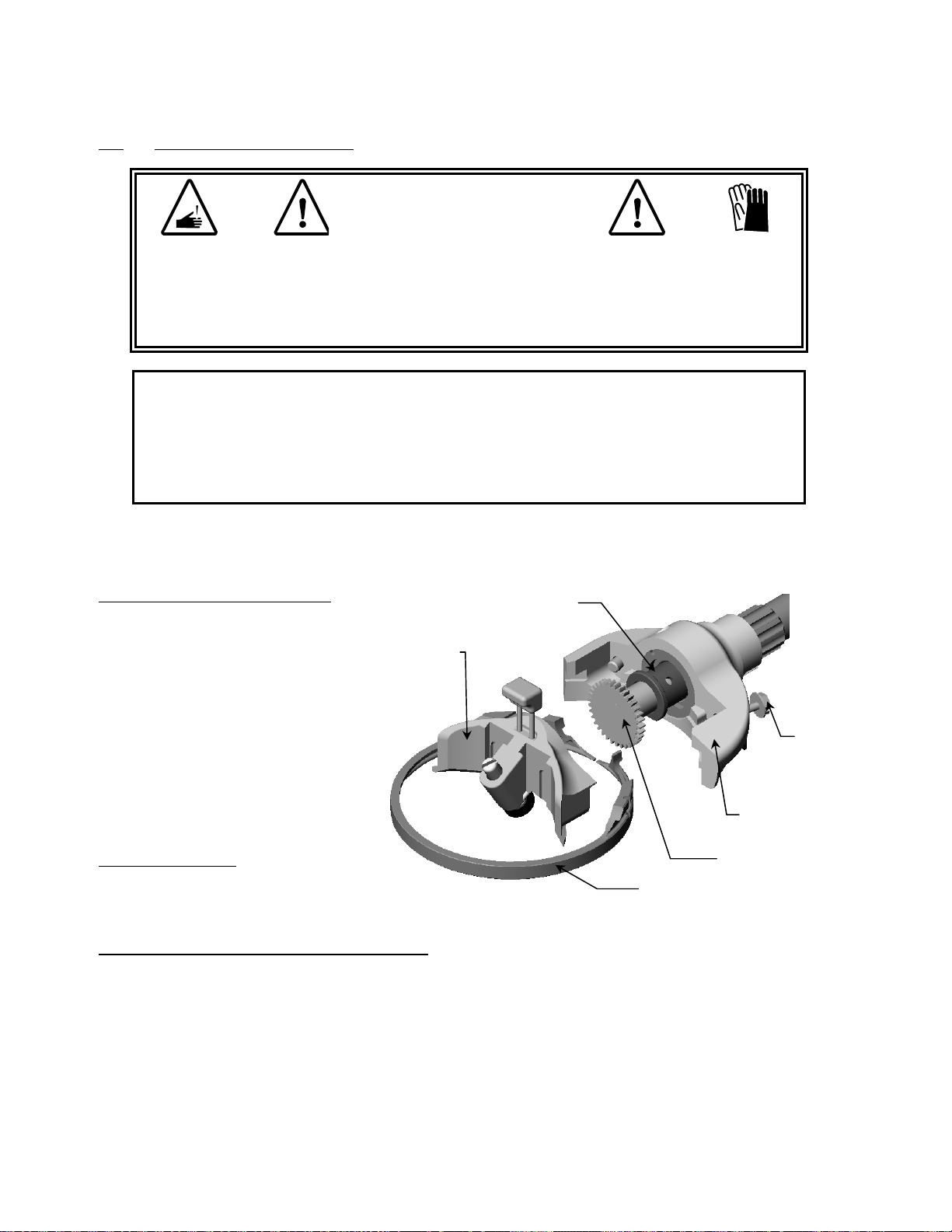
Removal Of The Blade Housing And Cover:
Loosen cover retaining screws until the
cover is free.
NOTE:
Pinion
Cover Plate
Frame
The screws will stay in the frame.
Remove the blade housing.
Pull the pinion out of the frame.
Blade
Housing
Cover Retaining
Screws (2)
Page 25

TECHNICAL BETTCHER LARGE MODULAR SERIES II WHIZARD
MANUAL INDUSTRIES, INC. REV. June 28, 2012
9.1 Disassembly Of Handpiece (Continued)
Removal Of The Bearing From The Frame :
The bearing is pulled out from the
front of the tool.
Use a screwdriver to reach into the
bearing and catch the bearing
grease groove.
While pulling upward, try to rotate
the bearing back and forth. Since
the bearing is not a press-fit, this
will work in most cases.
If the bearing will not come out, it
may be necessary to run a tap
into the bearing and pull on the
tap. If this is done, then the
Bearing
bearing must be replaced due
to damage.
The handpiece is now completely disassembled except for the cover retaining screws and
finger guard.
Finger Guard
(For Models 750M2 -1880M2 Only)
Cover Retaining Screws
NOTE:
The cover retaining screws do not normally need to removed. If they do need to be
removed, turn the screw while pulling down to engage the thread in the frame.
Page 26

TECHNICAL BETTCHER LARGE MODULAR SERIES II WHIZARD
MANUAL INDUSTRIES, INC. REV. June 28, 2012
9.2 Daily Inspections & Maintenance
WARNING
SHARP BLADES MAY CAUSE CUT INJURY!
ALWAYS DISCONNECT POWER AND REMOVE THE TOOL FROM THE
FLEX SHAFT CASING PRIOR TO SERVICING.
See Disassembly And Reassembly of Handpiece
WARNING
SHARP BLADES MAY CAUSE CUT INJURY!
AFTER SHARPENING, ALL ABRASIVE DUST MUST BE COMPLETELY
REMOVED FROM THE HANDPIECE. DISASSEMBLE THE UNIT AND
CAREFULLY WASH EACH PIECE WITH HOT, SOAPY WATER AND A
SMALL BRUSH.
Be Sure To Clean All Lubricant Out Of The
Inside Of Handpiece. Rinse And Dry Each Piece.
WARNING
SHARP BLADES MAY CAUSE CUT INJURY!
DO NOT ADJUST HANDLE OR THUMB SUPPORT WITH THE TRIMMER
RUNNING OR WITH BLADE INSTALLED.
Blade
Inspect the cutting edge height with Bettcher Blade Gauge.
Check for worn or chipped teeth.
Check for damage to the cutting edge.
Page 27

TECHNICAL BETTCHER LARGE MODULAR SERIES II WHIZARD
MANUAL INDUSTRIES, INC. REV. June 28, 2012
9.2 Daily Inspections & Maintenance (Continued)
Blade Housing Wear – For Models 750M2-1880M2
Inspect the inner diameter of the housing for wear.
Look for evidence of the blade rubbing the outer wall of the housing.
When holding the housing with a new blade installed, if the split in the housing touches the other side,
and the blade is still loose, the housing needs to be replaced. If a gap is seen, the housing is
acceptable.
Housing is Acceptable
Gap –
No Gap - Housing is Not
Acceptable
Blade Housing Wear – For Models 1000M2-1500M2
Inspect the inner diameter of the housing for wear.
When the housing wears to a point where the segments (grooves) are gone, the housing needs to be
replaced.
Segments
Page 28

TECHNICAL BETTCHER LARGE MODULAR SERIES II WHIZARD
MANUAL INDUSTRIES, INC. REV. June 28, 2012
9.2 Daily Inspections & Maintenance (Continued)
Pinion Gear
Check for worn or chipped teeth. Worn out teeth are indicated by rounded off and pointed tops on the teeth.
Bearing
Install a new pinion and move the pinion side to side.
If the bearing feels egg-shaped, it should be replaced.
As a rule of thumb, the bearing should be replaced at 500 hours of use or sooner.
Cover Plate
Look for signs of corrosion or wear on the cover.
Pay special attention to the area covering the gear teeth.
If the edge of the cover is worn, exposing the pinion and blade teeth, the cover should be replaced.
Hand Strap
Inspect the strap for hardening and cracks.
If any fibers, cuts, or cracks are showing, the strap should be replaced.
Knob
Inspect for cracks.
Make sure spring tension in the metal plate is adequate.
Make sure the metal plate is clean and moves freely.
Frame
Inspect the frame surfaces where the housing mounts.
Look for corrosion and any nicks or burrs that may prevent proper housing seating.
Inspect the housing locating key for damage.
Steeling Device
Inspect the surface condition of the carbide steel. If chipped or cracked it should be replaced.
Make sure the steeling device and the plunger are free to move.
The plunger and steel should be cleaned and oiled with mineral oil in order to keep free movement
and prevent build-up of dirt.
Depth Gauge and Depth Gauge Clamps
Inspect the depth gauge for wear or damage.
Make sure the depth gauge clamps are not bent.
Page 29

TECHNICAL BETTCHER LARGE MODULAR SERIES II WHIZARD
MANUAL INDUSTRIES, INC. REV. June 28, 2012
9.2 Daily Inspections & Maintenance (Continued)
Flex Shaft And Casing
Bearing
Inspect the casing for any cracks, tears, or
other wear. If any damage is found, replace
the casing.
Remove the flex shaft from the casing and
check for any flex shaft damage, such as
broken wires or kinking. If any damage is
detected, replace the flex shaft.
Reinsert the flex shaft into the casing, making
certain the flange of the flex shaft is pressed
against the bearing inside the casing.
Check the extension of the flexible shaft
driver at the motor end. The flexible shaft
driver should extend past the motor end
fitting. If the shaft extends less than 5/64”,
replace the casing.
Motor End
Fitting
Flex Shaft
Driver
Casing
Page 30

TECHNICAL BETTCHER LARGE MODULAR SERIES II WHIZARD
MANUAL INDUSTRIES, INC. REV. June 28, 2012
9.2 Daily Inspections & Maintenance (Continued)
Casing Replacement
When the casing needs to be replaced, the drive end assembly may be retained and reused.
Hold the casing (#1) in a vise.
Unscrew the drive end assembly (#4) by turning counterclockwise using the wrench flats on the drive
end assembly.
Unscrew and remove the nylon washer (#3), casing latch collar (#2) or lever mounting collar (#5)
from the casing.
Discard the casing but retain and reuse the drive end assembly (#4), the nylon washer (#3),
the casing latch collar (#2) – or the lever mounting collar (#5) and disconnect lever (#6).
7
1
2
5
3
4
6
To Reassemble the Drive End Assembly to a New Casing
If using the casing disconnect, place the disconnect lever (#6) onto the lever mounting collar (#5).
Slip the casing latch collar (#2) or lever mounting collar (#5) with disconnect lever (#6) onto the new
casing.
Thread the nylon washer (#3) onto the new casing.
Clean the threads of the new casing assembly and apply Loctite #242 Threadlocker or equivalent.
Screw the drive end assembly (#4) on the new casing.
Tighten by hand and then with a wrench while holding the casing by hand.
NOTE:
DO NOT hold the new casing in a vise or use pliers as
damage will occur. It is not necessary to over-tighten this joint.
Page 31

TECHNICAL BETTCHER LARGE MODULAR SERIES II WHIZARD
MANUAL INDUSTRIES, INC. REV. June 28, 2012
9.2 Daily Inspections & Maintenance (Continued)
Drive End Assembly Inspection And Replacement
Removal of the driver assembly
With one hand, pull the spring (#1) back to expose the knurled cap (#2) at the end of the tube.
Using the other hand, grip the knurled cap (#2) with a pair of pliers.
Using a 7/16” open end wrench, hold the flats on the drive end assembly (#3) and turn the knurled cap
(#2) counterclockwise.
Unscrew the knurled cap (#2) until the threads are free from the tube.
Pull the driver assembly (#4) out of the tube.
NOTE: Never use pliers on the tube as damage to the internal parts may occur.
3
1
2
4
Inspection of the driver assembly (See Figure Below)
Wipe off excess grease.
Inspect the split bearing (#5) for wear or damage. Replace if required.
Slide the knurled cap (#6) forward against the driver (#7).
Wiggle the bushing (#8) sideways to check for excessive movement. Movement
should be minimal.
7
6 8
5
Slide the bushing (#8) and washer (#9) forward
toward the driver (#7). If the gap is 1/16” or
greater, the driver should be replaced.
9
10
Check the coupling cross pin (#10). If there is any free play or movement, replace the driver
assembly.
Page 32

TECHNICAL BETTCHER LARGE MODULAR SERIES II WHIZARD
MANUAL INDUSTRIES, INC. REV. June 28, 2012
9.2 Daily Inspections & Maintenance (Continued)
Drive End Assembly Inspection And Replacement
Replacement of the Driver Assembly
Clean the threads on the tube and knurled cap.
Apply Whizard special grease to split bearing (#3) and bushing (#2).
Apply a small amount of Loctite #242 Threadlocker or equivalent to the threads on the
knurled cap (#1).
Pull the spring (#4) on the drive end assembly back with one hand and insert the driver
assembly in the tube.
Push in and tighten the knurled cap until it is flush with the end of the tube. Pliers may be
used for this however it is not necessary to tighten beyond hand tight.
Allow ½ hour dry time for the threadlocker before the assembly is put in service.
1
2
3
4
Replacement of the Split Bearing (#3)
Remove the driver assembly as described above.
Insert a small screwdriver into the split in the bearing.
Spread the bearing and slide over the shoulder on the driver.
Clean the surface of the coupling and apply Whizard special grease.
Hold the bearing with the inside cone facing the end of the coupling.
Push the bearing on until it snaps into position.
Install the driver assembly as described above.
Page 33

TECHNICAL BETTCHER LARGE MODULAR SERIES II WHIZARD
MANUAL INDUSTRIES, INC. REV. June 28, 2012
9.3 Blade Sharpening – Daily
CORRECT POSITION OF
STONE OR STEEL FOR
SHARPENING
BLADE CUTTING EDGE
WARNING
AFTER SHARPENING, ALL ABRASIVE DUST MUST BE COMPLETELY
REMOVED FROM THE HANDPIECE. DISASSEMBLE THE UNIT AND
CAREFULLY WASH EACH PIECE WITH HOT, SOAPY WATER AND A
SMALL BRUSH.
WARNING
SHARP BLADES MAY CAUSE CUT INJURY!
FOR PROPER PROTECTION OF HANDS, A PROTECTIVE GLOVE SHOULD
BE USED WHEN OPERATING THIS EQUIPMENT AND DURING THE
HANDLING OF BLADES.
The blade should be stoned or sharpened on a Whizard Model 210 Universal Blade
Sharpener or Bettcher® AutoEdge at the end of each work day. Be sure to clean the blade
first to remove all grease or meat particles which could coat the stone and greatly reduce its
effectiveness. In the event the stone becomes coated, simply scrub it using hot, soapy
water.
HAND STONING – Models 850M2/880M2/1000M2-1500M2/1850M2/1880M2:
With the motor running, apply the flat side of the stone to the outside of the blade as shown
in the illustration. The stone should be applied with the flat part of the stone resting on the
flat part of the blade edge to be ground, using a "back and forth" motion.
Use the Special Whizard steel to finish sharpening as described in the Operating Section.
Page 34
TECHNICAL BETTCHER LARGE MODULAR SERIES II WHIZARD
MANUAL INDUSTRIES, INC. REV. June 28, 2012
9.4 Assembly Of Handpiece
WARNING
SHARP BLADES MAY CAUSE CUT INJURY!
PROPER PROTECTION OF HANDS, A PROTECTIVE GLOVE SHOULD
FOR
BE USED WHEN OPERATING THIS EQUIPMENT AND DURING THE
HANDLING OF BLADES.
CAUTION
INSPECTION OF ALL PARTS FOR EXCESSIVE WEAR IS CRITICAL TO ENSURE
PROPER AND SAFE OPERATION. VIBRATION OR LOCK-UP MAY OCCUR AS
A RESULT OF THE USE OF EXCESSIVELY WORN PARTS.
Prior to assembly, be sure all parts are clean and have been inspected for wear per Section 9.2.
Handpiece Bearing Installation
Bearing
Push the handpiece bearing in
the frame bore and align the
bearing flat with the frame flat.
The bearing should go in with
Cover
Plate
minimal effort and not require
pressing.
Do not force the bearing in. If
it does not go in, check frame
Cover
Retaining
Screw
and bearing for damage or
build-up.
Frame
Pinion Installation
The pinion should fit freely into
Blade Housing
Pinion
the bearing.
Blade Housing And Cover Plate Installation
Set the blade housing on the frame and put the cover plate on.
While holding the cover plate firmly against the housing and frame start the two cover
retaining screws.
Tighten the screws lightly.
Page 35

TECHNICAL BETTCHER LARGE MODULAR SERIES II WHIZARD
MANUAL INDUSTRIES, INC. REV. June 28, 2012
9.4 Assembly Of Handpiece (Continued)
Grease Cup
Pick up the Whizard Trimmer
Pick up a spacer ring or optional thumb support
If the optional thumb support is used, align the thumb
support tab with one of the notches on the underside of
the frame
The optional thumb support should be located on the
opposite side of the grease cup
Frame
Notches
While holding the Trimmer, pick up a handle and align the four (4) handle tabs with
the four notches located on the threaded portion of the frame tube
Firmly push the handle towards the bottom of the spacer ring or optional thumb support,
and align the handle tabs with the notches on the front of the tube as shown
For the initial adjustment position, the short groove on the handle should be on top, as
shown.
NOTE: The handle can be adjusted to suit the operator and the work station by pulling the
handle back away from the frame and re-locating it on another set of notches on the frame
tube.
Screw on the handle retaining knob.
Tighten firmly but take care not to overtighten or the handle will be damaged.
Optional
Thumb
Support
Short Groove
Handle Tabs (4)
Page 36
Frame Tube Threads
And Notches
Handle
Retaining
Knob

TECHNICAL BETTCHER LARGE MODULAR SERIES II WHIZARD
MANUAL INDUSTRIES, INC. REV. June 28, 2012
9.4 Assembly Of Handpiece (Continued)
Installation Of The Hand Strap And Grease Cup
Push the threaded end of the grease cup through the round grommet end of the strap.
Be sure that the ribbed surface of the strap is on top as shown.
Reinstall the grease cup.
Weave the end of the strap down and back up through the slots in the flange of the
handle. The strap may be pulled through the slots to adjust for size.
An optional secondary strap has been provided with your Modular Series II Whizard
tool. To install the secondary strap :
Weave the secondary strap end through the opposite handle slots similar to the method
used to install the primary hand strap.
Bring the loose end of the strap across the tool and snap closed.
Optional
Secondary
Hand Strap
Primary
Hand
Strap
Page 37

TECHNICAL BETTCHER LARGE MODULAR SERIES II WHIZARD
MANUAL INDUSTRIES, INC. REV. June 28, 2012
9.4 Assembly Of Handpiece (Continued)
Installation Of The Depth Gauge
(For 880M2-S&B, 1880M2, 1400M2, 1500M2, 1932M2 and 1942M2 Only)
Cover Plate
Grooves
Slide the depth gauge downward
along the cover plate grooves until
the depth gauge clamps catch in
Depth
Gauge
Clamp
position.
Final height adjustment can be
made after the blade is installed.
Attachment
Screws (2)
Tighten the two attachment screws.
Model 880M2-B
Depth Gauge
Attachment
Screws (2)
Cover Plate
Grooves
Depth
Gauge
Model 1400M2
Depth
Gauge
Clamp
Installation Of The Adjustable Disc Gauge
(For 850M2, 1000M2 and 1300M2)
Slide the depth gauge downward along the
Cover
Plate
Grooves
cover plate grooves until the depth gauge
clamps catch in position.
Final height adjustment can be made after
the blade is installed.
Tighten the two attachment screws.
Attachment
Screws (2)
Model 1000M2-F
Page 38

TECHNICAL BETTCHER LARGE MODULAR SERIES II WHIZARD
MANUAL INDUSTRIES, INC. REV. June 28, 2012
9.4 Assembly Of Handpiece (Continued)
Installation of the Blade :
Turn the tool over so the blade side is up.
Spread open the blade housing with a screwdriver.
NOTE:
Leave a slight tension on the left cover screw so the blade housing will stay open on its own.
Insert a new blade in the housing.
Loosen the left cover screw so the housing will close.
BE CERTAIN THAT THE BLADE IS FREE TO ROTATE IN THE HOUSING. IF THE BLADE DOES NOT
ROTATE FREELY
Adjust the housing for proper running clearance. For more information, refer to section 8.3,
Operating Procedures.
, IT MAY CAUSE THE TOOL TO ROTATE IN THE HAND.
9.5 Preventive Maintenance
CAUTION
USE ONLY BETTCHER WHIZLUBE
At least once each week, more frequently for multi-shift operation, the flex shaft casing should be
cleaned, inspected and lubricated as follows:
Exterior Of Casing – Clean the exterior of the casing with a mild detergent. For best results, use
Whizard® EXTRA Heavy Duty Cleaner, diluted according to the directions on the container.
Flex Shafts - Clean the shaft after 20 hours of operation by wiping off the old grease with a dry
cloth. Avoid the use of any liquids on the shaft. Spray the shaft with a generous amount of
Bettcher WhizLube as it is pushed back into the casing. Inspect the casing support for wear,
cracks, or chips.
CAUTION
DO NOT USE ANY HYDROCARBON SOLVENTS OR MINERAL OIL ON, OR IN, THE
CASING.
Page 39

TECHNICAL BETTCHER LARGE MODULAR SERIES II WHIZARD
MANUAL INDUSTRIES, INC. REV. June 28, 2012
SECTION 10.0 Cleaning
CAUTION
CASINGS, FLEX SHAFTS, AND HANDPIECES SHOULD BE REMOVED
RIOR TO AREA CLEANUP.
P
10.1 Periodic Cleaning During Use
Remove meat particles and rinse with warm soapy water. Wash the Whizard Trimmer
with warm cleaning solution. For best results, clean the Whizard® Trimmer with E
XTRA
Heavy Duty Cleaner, diluted according to the directions on the container. Rinse
thoroughly with water.
10.2 Cleaning After Daily Use
Disassemble and clean thoroughly daily.
Remove the blade and blade housing and clean them with a brush and cleaner. For best
results, clean the Whizard® Trimmer with E
XTRA Heavy Duty Cleaner, diluted according
to the directions on the container. Rinse thoroughly with water and dry.
Remove the hand strap from the handpiece per the instructions in Section 9.2 Clean these
in warm soapy water.
Before assembly, rinse well with clean water, dry, and assemble per instructions in Section
9.4.
10.3 Cleaning Solutions
Avoid the use of aggressive cleaning products as they will damage the aluminum handle
assembly.
Page 40

TECHNICAL BETTCHER LARGE MODULAR SERIES II WHIZARD
MANUAL INDUSTRIES, INC. REV. June 28, 2012
SECTION 11.0 Spare Parts List
Bettcher Industries, Inc. proudly manufactures
quality parts for your Bettcher equipment.
For optimum performance of your Bettcher
equipment, use only parts manufactured by
Bettcher Industries, Inc.
Page 41

TECHNICAL BETTCHER LARGE MODULAR SERIES II WHIZARD
MANUAL INDUSTRIES, INC. REV. June 28, 2012
11.1 Head Assembly – 750M2
2
3
1
13
11
4
10
12
5
6
8
7
9
Page 42

TECHNICAL BETTCHER LARGE MODULAR SERIES II WHIZARD
MANUAL INDUSTRIES, INC. REV. June 28, 2012
11.1 Head Assembly – 750M2
ITEM DESCRIPTION
Handpiece Assembly (Includes the Head Assy. Plus Items 1, 2 (Flanged Only), 11, 12, 13)
XX-Small 183722 184580 183724 184581
X-Small 183386 184582 183390 184583
Small 183387 184584 183391 184585
Medium 183388 184586 183392 184587
Large 183389 184588 183393 184589
Disconnect Handpiece Assembly (Includes the Head Assy. Plus Items 1, 2 (Flanged Only), 11, 12, 13)
XX-Small 183721 184806 183723 184807
X-Small 183378 184808 183382 184809
Small 183379 184810 183383 184811
Medium 183380 184812 183384 184813
Large 183381 184814 183385 184815
Head Assembly (Includes Items 3 - 10) 183021 183022
1 Handle Retaining Knob 183086 183086
2 Hand Strap – Primary 183065 183065
Hand Strap – Secondary
(Not Shown)
3 Grease Cup 173191 173191
Parts for Grease Cup (Not Shown)
Retainer Ring Only 173190 173190
Bulb and Washer 173208 173208
Base and Fitting 173187 173187
4 Frame Assembly 183896 183897
5 Bearing 183060 183060
6 Pinion 183063 183063
7 Cover 183088 183088
8 Blade Housing 183070 183070
9 Blade 183071 183071
10 Cover Retaining Screw (2 required) 183654 183654
11 Handle Spacer Ring 183120 183120
Handle Spacer Ring for XX-Small 163313 163313
12 Thumb Support (Gray) 163207 163207
13
See Section 11.20 for Handle Options
750M2 RH 750M2 LH
Flanged Flangeless Flanged Flangeless
183121 183121
Page 43

TECHNICAL BETTCHER LARGE MODULAR SERIES II WHIZARD
MANUAL INDUSTRIES, INC. REV. June 28, 2012
11.2 Head Assembly – 850M2
2
3
11
4
12
1
14
10
5
13a
13c
13d
13b
13
6
7
8
9
Page 44

TECHNICAL BETTCHER LARGE MODULAR SERIES II WHIZARD
MANUAL INDUSTRIES, INC. REV. June 28, 2012
11.2 Head Assembly – 850M2
ITEM DESCRIPTION
Handpiece Assembly (Includes the Head Assy. Plus Items 1, 2 (Flanged Only), 11, 12, 14)
XX-Small 183726 184590 183728 184591
X-Small 183402 184592 183406 184593
Small 183403 184594 183407 184595
Medium 183404 184596 183408 184597
Large 183405 184598 183409 184599
Disconnect Handpiece Assembly (Includes the Head Assy. Plus Items 1, 2 (Flanged Only), 11, 12, 14)
XX-Small 183725 184816 183727 184817
X-Small 183394 184818 183398 184819
Small 183395 184820 183399 184821
Medium 183396 184822 183400 184823
Large 183397 184824 183401 184825
Head Assembly (Includes Items 3 – 10)
1 Handle Retaining Knob 183086 183086
2 Hand Strap – Primary 183065 183065
Hand Strap – Secondary
(Not Shown)
3 Grease Cup 173191 173191
Parts for Grease Cup (Not Shown)
Retainer Ring Only 173190 173190
4
5
6
7
8
9
10
11
Frame Assembly 183896 183897
Bearing 183060 183060
Pinion 183063 183063
Cover with Special Steeling
Device
Blade Housing 183070 183070
Blade 183072 183072
Cover Retaining Screw (2
required)
Handle Spacer Ring 183120 183120
Handle Spacer Ring for XXSmall
12 Thumb Support (Gray) 163207 163207
13
13a
13b
13c
13d
14
Disc Gauge Kit 850M2-S
See Section 11.20 for Handle Options
Bulb and Washer 173208 173208
Base and Fitting 173187 173187
Repair Kit (Not Shown) 183474 183474
(Optional)
Parts for Disc Gauge
Knob 183791 183791
Frame 183798 183798
Spring 121635 121635
Disc Assembly 183799 183799
850M2 RH 850M2 LH
Flanged Flangeless Flanged Flangeless
183023 183024
183121 183121
183056 183056
183654 183654
163313 163313
183801 183801
Page 45

TECHNICAL BETTCHER LARGE MODULAR SERIES II WHIZARD
MANUAL INDUSTRIES, INC. REV. June 28, 2012
11.3 Head Assembly – 880M2-B
1
2
3
12
4
5
6
7
8
11
9
10
13
14
Page 46

TECHNICAL BETTCHER LARGE MODULAR SERIES II WHIZARD
MANUAL INDUSTRIES, INC. REV. June 28, 2012
11.3 Head Assembly – 880M2-B
ITEM DESCRIPTION
880M2-B RH 880M2-B LH
Flanged Flangeless Flanged Flangeless
Handpiece Assembly (Includes the Head Assy. Plus Items 1, 2 (Flanged Only), 12, 13, 14)
XX-Small 183730 184600 183732 184601
X-Small 183418 184602 183422 184603
Small 183419 184604 183423 184605
Medium 183420 184606 183424 184607
Large 183421 184608 183425 184609
Disconnect Handpiece Assembly (Includes the Head Assy. Plus Items 1, 2 (Flanged Only), 12, 13, 14)
XX-Small 183729 184826 183731 184827
X-Small 183410 184828 183414 184829
Small 183411 184830 183415 184831
Medium 183412 184832 183416 184833
Large 183413 184834 183417 184835
Head Assembly (Includes Items 3 - 11) 183025 183026
1 Handle Retaining Knob 183086 183086
2 Hand Strap – Primary 183065 183065
Hand Strap – Secondary (Not Shown) 183121 183121
3 Grease Cup 173191 173191
Parts for Grease Cup (Not Shown)
Retainer Ring Only 173190 173190
Bulb and Washer 173208 173208
Base and Fitting 173187 173187
4 Frame Assembly 183896 183897
5 Bearing 183060 183060
6 Pinion 183063 183063
7 Cover with Special Steeling Device 183056 183056
Repair Kit (Not Shown) 183474 183474
8 Depth Gauge Assembly 183075 183075
9 Blade Housing 183070 183070
10 Blade 183072 183072
11 Cover Retaining Screw (2 required) 183654 183654
12 Handle Spacer Ring 183120 183120
Handle Spacer Ring for XX-Small 163313 163313
13 Thumb Support (Gray) 163207 163207
14
See Section 11.20 for Handle Options
Page 47

TECHNICAL BETTCHER LARGE MODULAR SERIES II WHIZARD
MANUAL INDUSTRIES, INC. REV. June 28, 2012
11.4 Head Assembly – 880M2-S
2
3
12
4
13
1
14
5
6
7
8
11
9
10
Page 48

TECHNICAL BETTCHER LARGE MODULAR SERIES II WHIZARD
MANUAL INDUSTRIES, INC. REV. June 28, 2012
11.4 Head Assembly – 880M2-S
ITEM DESCRIPTION
880M2-S RH 880M2-S LH
Flanged Flangeless Flanged Flangeless
Handpiece Assembly (Includes the Head Assy. Plus Items 1, 2 (Flanged Only), 12, 13, 14)
XX-Small 183734 184610 183736 184611
X-Small 183434 184612 183438 184613
Small 183435 184614 183439 184615
Medium 183436 184616 183440 184617
Large 183437 184618 183441 184618
Disconnect Handpiece Assembly (Includes the Head Assy. Plus Items 1, 2 (Flanged Only), 12, 13, 14)
XX-Small 183733 184836 183735 184837
X-Small 183426 184838 183430 184839
Small 183427 184840 183431 184841
Medium 183428 184842 183432 184843
Large 183429 184844 183433 184845
Head Assembly (Includes Items 3 - 11) 183027 183028
1
Handle Retaining Knob 183086 183086
2
Hand Strap – Primary 183065 183065
Hand Strap – Secondary
(Not Shown)
3
Grease Cup 173191 173191
183121 183121
Parts for Grease Cup (Not Shown)
4
5
6
7
8
9
10
11
12
Frame Assembly 183896 183897
Bearing 183060 183060
Pinion 183063 183063
Cover with Special Steeling Device 183056 183056
Depth Gauge Assembly 183076 183076
Blade Housing 183070 183070
Blade 183072 183072
Cover Retaining Screw (2 required) 183654 183654
Handle Spacer Ring 183120 183120
Handle Spacer Ring for XX-Small 163313 163313
Retainer Ring Only 173190 173190
Bulb and Washer 173208 173208
Base and Fitting 173187 173187
Repair Kit (Not Shown) 183474 183474
13 Thumb Support (Gray) 163207 163207
14
See Section 11.20 for Handle Options
Page 49

TECHNICAL BETTCHER LARGE MODULAR SERIES II WHIZARD
MANUAL INDUSTRIES, INC. REV. June 28, 2012
11.5 Head Assembly – 1850M2
2
3
1
14
11
4
12
13a
5
10
6
13b
13c
13
8
13d
9
7
Page 50

TECHNICAL BETTCHER LARGE MODULAR SERIES II WHIZARD
MANUAL INDUSTRIES, INC. REV. June 28, 2012
11.5 Head Assembly – 1850M2
ITEM DESCRIPTION
1850M2 RH 1850M2 LH
Flanged Flangeless Flanged Flangeless
Handpiece Assembly (Includes the Head Assy. Plus Items 1, 2 (Flanged Only), 11, 12, 14)
XX-Small 183738 184620 183740 184621
X-Small 183450 184622 183454 184623
Small 183451 184624 183455 184625
Medium 183452 184626 183456 184627
Large 183453 184628 183457 184629
Disconnect Handpiece Assembly (Includes the Head Assy. Plus Items 1, 2 (Flanged Only), 11, 12, 14)
XX-Small 183737 184846 183739 184847
X-Small 183442 184848 183446 184849
Small 183443 184850 183447 184851
Medium 183444 184852 183448 184853
Large 183445 184854 183449 184855
Head Assembly (Includes Items 3 – 10) 183029 183030
1 Handle Retaining Knob 183086 183086
2 Hand Strap – Primary 183065 183065
Hand Strap – Secondary (Not
Shown)
183121 183121
3 Grease Cup 173191 173191
Parts for Grease Cup (Not Shown)
Retainer Ring Only 173190 173190
Bulb and Washer 173208 173208
Base and Fitting 173187 173187
4 Frame Assembly 183896 183897
5 Bearing 183060 183060
6 Pinion 183063 183063
7
Cover with Special Steeling Device
183053 183053
Repair Kit (Not Shown) 183476 183476
8 Blade Housing 183070 183070
9 Blade 183073 183073
10
Cover Retaining Screw
(2 required)
183654 183654
11 Handle Spacer Ring 183120 183120
Handle Spacer Ring for XX-Small 163313 163313
12 Thumb Support (Gray) 163207 163207
13
Disc Gauge Kit 1850M2-K
(Optional)
184479 184479
Parts for Disc Gauge:
13a Knob 183791 183791
13b Frame 183798 183798
13c Spring 121635 121635
13d Disc Assembly 184481 184481
14
See Section 11.20 for Handle Options
Page 51

TECHNICAL BETTCHER LARGE MODULAR SERIES II WHIZARD
MANUAL INDUSTRIES, INC. REV. June 28, 2012
11.6 Head Assembly – 1880M2
2
3
12
4
13
1
14
5
6
7
8
11
9
10
Page 52

TECHNICAL BETTCHER LARGE MODULAR SERIES II WHIZARD
MANUAL INDUSTRIES, INC. REV. June 28, 2012
11.6 Head Assembly – 1880M2
ITEM DESCRIPTION
1880M2 RH 1880M2 LH
Flanged Flangeless Flanged Flangeless
Handpiece Assembly (Includes the Head Assy. Plus Items 1, 2 (Flanged Only), 12, 13, 14)
XX-Small 183742 184630 183744 184631
X-Small 183466 184632 183470 184633
Small 183467 184634 183471 184635
Medium 183468 184636 183472 184637
Large 183469 184638 183473 184639
Disconnect Handpiece Assembly (Includes the Head Assy. Plus Items 1, 2 (Flanged Only), 11, 12, 14)
XX-Small 183741 184856 183743 184857
X-Small 183458 184858 183462 184859
Small 183459 184860 183463 184861
Medium 183460 184862 183464 184863
Large 183461 184864 183465 184865
Head Assembly (Includes Items 3 - 11) 183031 183032
1 Handle Retaining Knob 183086 183086
2 Hand Strap – Primary 183065 183065
Hand Strap – Secondary (Not Shown) 183121 183121
3 Grease Cup 173191 173191
Parts for Grease Cup (Not Shown)
Retainer Ring Only 173190 173190
Bulb and Washer 173208 173208
Base and Fitting 173187 173187
4 Frame Assembly 183896 183897
5 Bearing 183060 183060
6 Pinion 183063 183063
7 Cover with Special Steeling Device 183053 183053
Repair Kit (Not Shown) 183476 183476
8 Depth Gauge Assembly 183077 183077
9 Blade Housing 183070 183070
10 Blade 183073 183073
11 Cover Retaining Screw (2 required) 183654 183654
12 Handle Spacer Ring 183120 183120
Handle Spacer Ring for XX-Small 163313 163313
13 Thumb Support (Gray) 163207 163207
14
See Section 11.20 for Handle Options
Page 53

TECHNICAL BETTCHER LARGE MODULAR SERIES II WHIZARD
a
MANUAL INDUSTRIES, INC. REV. June 28, 2012
11.7 Head Assembly – 1000M2
1
2
14
3
11
4
12
10
5
6
13
13b
7
8
13c
9
13d
13
Page 54

TECHNICAL BETTCHER LARGE MODULAR SERIES II WHIZARD
MANUAL INDUSTRIES, INC. REV. June 28, 2012
11.7 Head Assembly – 1000M2
ITEM DESCRIPTION
Handpiece Assembly (Includes the Head Assy. Plus Items 1, 2 (Flanged Only), 11, 12, 14)
Disconnect Handpiece Assembly (Includes the Head Assy. Plus Items 1, 2 (Flanged Only), 11, 12, 14)
Head Assembly (Includes Items 3 – 10) 183169 183170
1 Handle Retaining Knob 183086 183086
2 Hand Strap – Primary 183065 183065
3 Grease Cup 173191 173191
4 Frame Assembly 184362 184363
5 Bearing 183060 183060
6 Pinion 183154 183154
7 Cover with Special Steeling Device 183163 183163
8 Blade Housing 183143 183143
9 Blade 183141 183141
10 Cover Retaining Screw (2 required) 183654 183654
11 Handle Spacer Ring 183120 183120
XX-Small
X-Small
Small
Medium
Large
XX-Small
X-Small
Small
Medium
Large
Hand Strap – Secondary (Not Shown) 183121 183121
Parts for Grease Cup (Not Shown)
Retainer Ring Only 173190 173190
Bulb and Washer 173208 173208
Base and Fitting 173187 173187
Repair Kit (Not Shown) 183477 183477
Handle Spacer Ring for XX-Small
1000M2 RH 1000M2 LH
Flanged Flangeless Flanged Flangeless
183746 184640 183748 184641
183185 184642 183189 184643
183186 184644 183190 184645
183187 184646 183191 184647
183188 184648 183192 184649
183745 184866 183747 184867
183177 184868 183181 184869
183178 184870 183182 184871
183179 184872 183183 184873
183180 184874 183184 184875
163313 163313
12 Thumb Support (Gray) 163207 163207
13 Disc Gauge Kit (Optional)
1000M2-S (Skinner) 183792 183792
1000M2-F (Fat) 183793 183793
1000M2-N (Special) 184365 184365
Parts for Disc Gauge
13a Knob 183791 183791
13b Frame Assembly 183784 183784
13c Spring 121635 121635
13d Disc Assembly (S) 183787 183787
Disc Assembly (F) 183788 183788
Disc Assembly (N) 184367 184367
14
See Section 11.20 for Handle Options
Page 55

TECHNICAL BETTCHER LARGE MODULAR SERIES II WHIZARD
MANUAL INDUSTRIES, INC. REV. June 28, 2012
11.8 Head Assembly – 1300M2
1
2
14
3
11
4
12
10
5
6
13a
7
8
13b
9
13d
13c
13
Page 56

TECHNICAL BETTCHER LARGE MODULAR SERIES II WHIZARD
MANUAL INDUSTRIES, INC. REV. June 28, 2012
11.8 Head Assembly – 1300M2
ITEM DESCRIPTION
Handpiece Assembly (Includes the Head Assy. Plus Items 1, 2 (Flanged Only), 11, 12, 14)
XX-Small 183750 184650 183752 184651
X-Small 183201 184652 183205 184653
Small 183202 184654 183206 184655
Medium 183203 184656 183207 184657
Large 183204 184658 183208 184659
Disconnect Handpiece Assembly (Includes the Head Assy. Plus Items 1, 2 (Flanged Only), 11, 12, 14)
XX-Small 183749 184876 183751 184877
X-Small 183193 184878 183197 184879
Small 183194 184880 183198 184881
Medium 183195 184882 183199 184883
Large 183196 184884 183200 184885
Head Assembly (Includes Items 3 – 10) 183171 183172
1 Handle Retaining Knob 183086 183086
2 Hand Strap – Primary 183065 183065
Hand Strap – Secondary (Not Shown) 183121 183121
3 Grease Cup 173191 173191
Parts forCup (Not Shown)
Retainer Ring Only 173190 173190
4 Frame Assembly 184362 184363
5 Bearing 183060 183060
6 Pinion 183154 183154
7 Cover with Special Steeling Device 183164 183164
Repair Kit (Not Shown) 183478 183478
8 Blade Housing 183143 183143
9 Blade 183142 183142
10 Cover Retaining Screw (2 required) 183654 183654
11 Handle Spacer Ring 183120 183120
Handle Spacer Ring for XX-Small 163313 163313
Bulb and Washer 173208 173208
Base and Fitting 173187 173187
1300M2 RH 1300M2 LH
Flanged Flangeless Flanged Flangeless
12 Thumb Support (Gray) 163207 163207
13 Disc Gauge Kit (Optional)
1300M2-S (Skinner) 183794 183794
1300M2-F (Fat) 183795 183795
1300M2-K (Kebab) 184993 184993
Parts for Disc Gauge
13a Knob 183791 183791
13b Frame 183784 183784
13c Spring 121635 121635
13d Disc Assembly (S) 183789 183789
Disc Assembly (F) 183790 183790
Disc Assembly (K) 184994 184994
14
See Section 11.20 for Handle Options
Page 57

TECHNICAL BETTCHER LARGE MODULAR SERIES II WHIZARD
MANUAL INDUSTRIES, INC. REV. June 28, 2012
11.9 Head Assembly – 1400M2
1
2
8
3
12
4
11
5
6
7
9
10
14
13
Page 58

TECHNICAL BETTCHER LARGE MODULAR SERIES II WHIZARD
MANUAL INDUSTRIES, INC. REV. June 28, 2012
11.9 Head Assembly – 1400M2
ITEM DESCRIPTION
Handpiece Assembly (Includes the Head Assy. Plus Items 1, 2 (Flanged Only), 12, 13, 14)
XX-Small 183754 184660 183756 184661
X-Small 183217 184662 183221 184663
Small 183218 184664 183222 184665
Medium 183219 184666 183223 184667
Large 183220 184668 183224 184669
Disconnect Handpiece Assembly (Includes the Head Assy. Plus Items 1, 2 (Flanged Only), 12, 13, 14)
XX-Small 183753 184886 183755 184887
X-Small 183209 184888 183213 184889
Small 183210 184890 183214 184891
Medium 183211 184892 183215 184893
Large 183212 184894 183216 184895
Head Assembly (Includes Items 3 – 11) 183173 183174
1 Handle Retaining Knob 183086 183086
2 Hand Strap – Primary 183065 183065
Hand Strap – Secondary (Not Shown) 183121 183121
3 Grease Cup 173191 173191
Parts for Grease Cup (Not Shown)
Retainer Ring Only 173190 173190
Bulb and Washer 173208 173208
Base and Fitting 173187 173187
4 Frame Assembly 184362 184363
5 Bearing 183060 183060
6 Pinion 183154 183154
7 Cover with Special Steeling Device 183164 183164
Repair Kit (Not Shown) 183478 183478
8 Depth Gauge Assembly 183159 183159
9 Blade Housing 183143 183143
10 Blade 183142 183142
11 Cover Retaining Screw (2 required) 183654 183654
12 Handle Spacer Ring 183120 183120
Handle Spacer Ring for XX-Small 163313 163313
13 Thumb Support (Gray) 163207 163207
14
See Section 11.20 for Handle Options
1400M2 RH 1400M2 LH
Flanged Flangeless Flanged Flangeless
Page 59

TECHNICAL BETTCHER LARGE MODULAR SERIES II WHIZARD
MANUAL INDUSTRIES, INC. REV. June 28, 2012
11.10 Head Assembly – 1500M2
2
3
1
14
12
4
11
13
5
6
7
9
10
8
Page 60

TECHNICAL BETTCHER LARGE MODULAR SERIES II WHIZARD
MANUAL INDUSTRIES, INC. REV. June 28, 2012
11.10 Head Assembly – 1500M2
ITEM DESCRIPTION
Handpiece Assembly (Includes the Head Assy. Plus Items 1, 2 (Flanged Only), 12, 13, 14)
Disconnect Handpiece Assembly (Includes the Head Assy. Plus Items 1, 2 (Flanged Only), 12, 13, 14)
Head Assembly (Includes Items 3 – 11) 183175 183176
10 Blade 183141 183141
11 Cover Retaining Screw (2 required) 183654 183654
12
13 Thumb Support (Gray) 163207 163207
14
XX-Small 183758 184670 183760 184671
X-Small 183233 184672 183237 184673
Small 183234 184674 183238 184675
Medium 183235 184676 183239 184677
Large 183236 184678 183240 184679
XX-Small 183757 184896 183759 184897
X-Small 183225 184898 183229 184899
Small 183226 184900 183230 184901
Medium 183227 184902 183231 184903
Large 183228 184904 183232 184905
1 Handle Retaining Knob 183086 183086
2 Hand Strap – Primary 183065 183065
Hand Strap – Secondary (Not Shown) 183121 183121
3 Grease Cup 173191 173191
Parts for Grease Cup (Not Shown)
Retainer Ring Only 173190 173190
Bulb and Washer 173208 173208
Base and Fitting 173187 173187
4 Frame Assembly 184362 184363
5 Bearing 183060 183060
6 Pinion 183154 183154
7 Cover with Special Steeling Device 183163 183163
Repair Kit (Not Shown) 183477 183477
8 Depth Gauge Assembly 183160 183160
9 Blade Housing 183143 183143
Handle Spacer Ring 183120 183120
Handle Spacer Ring for XX-Small 163313 163313
See Section 11.20 for Handle Options
1500M2 RH 1500M2 LH
Flanged Flangeless Flanged Flangeless
Page 61

TECHNICAL BETTCHER LARGE MODULAR SERIES II WHIZARD
MANUAL INDUSTRIES, INC. REV. June 28, 2012
11.11 Head Assembly – 1930M2
2
3
11
4
10
5
6
8
9
7
1
13
12
Page 62

TECHNICAL BETTCHER LARGE MODULAR SERIES II WHIZARD
MANUAL INDUSTRIES, INC. REV. June 28, 2012
11.11 Head Assembly – 1930M2
ITEM DESCRIPTION
Handpiece Assembly (Includes the Head Assy. Plus Items 1, 2 (Flanged Only), 11, 12, 13)
Disconnect Handpiece Assembly (Includes the Head Assy. Plus Items 1, 2 (Flanged Only), 11, 12, 13)
Head Assembly (Includes Items 3 – 10) 185053 185054
1
2
3
4
5
6
7
8
9
10
11
12
13
Small
Medium
Large
Small
Medium
Large
Handle Retaining Knob
Hand Strap – Primary
Hand Strap – Secondary
(Not Shown)
Grease Cup
Parts for Grease Cup (Not Shown)
Retainer Ring Only
Bulb and Washer
Base and Fitting
Frame
Bearing
Pinion
Cover with Special Steeling
Device
Repair Kit (Not Shown) 183477
Blade Housing
Blade
Cover Retaining Screw (2
required)
Handle Spacer Ring
Thumb Support (Gray)
See Section 11.20 for Handle Options
1930M2 RH 1930M2 LH
Flanged Flangeless Flanged Flangeless
185010 184690 185013 184691
185011 184692 185014 184693
185012 184694 185015 184695
185004 184916 185007 184917
185005 184918 185008 184919
185006 184920 185009 184921
183086 183086
183065 183065
183121 183121
173191 173191
173190 173190
173208 173208
173187 173187
185061 185062
183060 183060
185063 185063
185071 185071
183477
185065 185065
185066 185066
185075 185075
183120 183120
163207 163207
Page 63

TECHNICAL BETTCHER LARGE MODULAR SERIES II WHIZARD
MANUAL INDUSTRIES, INC. REV. June 28, 2012
11.12 Head Assembly – 1932M2
1
2
14
3
12
13
11
4
5
6
7
9
8
10
Page 64

TECHNICAL BETTCHER LARGE MODULAR SERIES II WHIZARD
MANUAL INDUSTRIES, INC. REV. June 28, 2012
11.12 Head Assembly – 1932M2
ITEM DESCRIPTION
Handpiece Assembly (Includes the Head Assy. Plus Items 1, 2 (Flanged Only), 12, 13, 14)
Small 185094 184696 185097 184697
Medium 185095 184698 185098 184699
Large 185096 184700 185099 184701
Disconnect Handpiece Assembly (Includes the Head Assy. Plus Items 1, 2 (Flanged Only), 12, 13, 14)
Small 185088 184922 185091 184923
Medium 185089 184924 185092 184925
Large 185090 184926 185093 184927
Head Assembly (Includes Items 3 – 11) 185112 185113
1 Handle Retaining Knob 183086 183086
2 Hand Strap – Primary 183065 183065
Hand Strap – Secondary (Not Shown) 183121 183121
3 Grease Cup 173191 173191
Parts for Grease Cup (Not Shown)
Retainer Ring Only 173190 173190
Bulb and Washer 173208 173208
Base and Fitting 173187 173187
4 Frame 185061 185062
5 Bearing 183060 183060
6 Pinion 185063 185063
7 Cover with Special Steeling Device 185071 185071
Repair Kit (Not Shown)
8 Depth Gauge Assembly
9 Blade Housing 185065 185065
10 Blade 185066 185066
11 Cover Retaining Screw (2 required) 185075 185075
12 Handle Spacer Ring 183120 183120
13
14
Thumb Support (Gray)
See Section 11.20 for Handle Options
1932M2 RH 1932M2 LH
Flanged Flangeless Flanged Flangeless
183477
185116
163207 163207
183477
185116
Page 65

TECHNICAL BETTCHER LARGE MODULAR SERIES II WHIZARD
MANUAL INDUSTRIES, INC. REV. June 28, 2012
11.13 Head Assembly – 1933M2
1
2
14
3
12
11
13
4
5
8a
6
8b
9
8c
7
8d
10
8
Page 66

TECHNICAL BETTCHER LARGE MODULAR SERIES II WHIZARD
MANUAL INDUSTRIES, INC. REV. June 28, 2012
11.13 Head Assembly – 1933M2
ITEM DESCRIPTION
Handpiece Assembly (Includes the Head Assy. Plus Items 1, 2 (Flanged Only), 12, 13, 14)
Small 185022 184702 185025 184703
Medium 185023 184704 185026 184705
Large 185024 184706 185027 184707
Disconnect Handpiece Assembly (Includes the Head Assy. Plus Items 1, 2 (Flanged Only), 12, 13, 14)
Small 185016 184928 185019 184929
Medium 185017 184930 185020 184931
Large 185018 184932 185021 184933
Head Assembly (Includes Items 3 – 11) 185055 185056
1 Handle Retaining Knob 183086 183086
2 Hand Strap – Primary 183065 183065
Hand Strap – Secondary (Not Shown) 183121 183121
3 Grease Cup 173191 173191
Parts for Grease Cup (Not Shown)
Retainer Ring Only 173190 173190
Bulb and Washer 173208 173208
Base and Fitting 173187 173187
4 Frame 185061 185062
5 Bearing 183060 183060
6 Pinion 185063 185063
7 Cover with Special Steeling Device 185071 185071
Repair Kit (Not Shown) 183477 183477
8 Disc Gauge Assembly (Optional) 185077 185077
Parts for Disc Gauge
8a Frame Assembly 185079 185079
8b Knob 183791 183791
8c Spring 121635 121635
8d Disc Assembly 185082 185082
9 Blade Housing 185065 185065
10 Blade 185066 185066
11 Cover Retaining Screw (2 required) 185075 185075
12 Handle Spacer Ring 183120 183120
13 Thumb Support (Gray) 163207 163207
14
See Section 11.20 for Handle Options
1933M2 RH 1933M2 LH
Flanged Flangeless Flanged Flangeless
Page 67

TECHNICAL BETTCHER LARGE MODULAR SERIES II WHIZARD
MANUAL INDUSTRIES, INC. REV. June 28, 2012
11.14 Head Assembly – 1940M2
2
3
11
1
13
12
4
10
5
6
8
7
9
Page 68

TECHNICAL BETTCHER LARGE MODULAR SERIES II WHIZARD
MANUAL INDUSTRIES, INC. REV. June 28, 2012
11.14 Head Assembly – 1940M2
ITEM DESCRIPTION
1940M2 RH 1940M2 LH
Flanged Flangeless Flanged Flangeless
Handpiece Assembly (Includes the Head Assy. Plus Items 1, 2 (Flanged Only), 11, 12, 13)
Small 185034 184708 185037 184709
Medium 185035 184710 185038 184711
Large 185036 184712 185039 184713
Disconnect Handpiece Assembly (Includes the Head Assy. Plus Items 1, 2 (Flanged Only), 11, 12, 13)
Small 185028 184934 185031 184935
Medium 185029 184936 185032 184937
Large 185030 184938 185033 184939
Head Assembly (Includes Items 3 – 10) 185057 185058
1 Handle Retaining Knob 183086 183086
2 Hand Strap – Primary 183065 183065
Hand Strap – Secondary (Not Shown) 183121 183121
3 Grease Cup 173191 173191
Parts for Grease Cup (Not Shown)
Retainer Ring Only 173190 173190
Bulb and Washer 173208 173208
Base and Fitting 173187 173187
4 Frame 185061 185062
5 Bearing 183060 183060
6 Pinion 185063 185063
7 Cover with Special Steeling Device 185072 185072
Repair Kit (Not Shown) 183478 183478
8 Blade Housing 185065 185065
9 Blade 185068 185068
10 Cover Retaining Screw (2 required) 185075 185075
11 Handle Spacer Ring 183120 183120
12
13
Thumb Support (Gray)
See Section 11.20 for Handle Options
163207 163207
Page 69

TECHNICAL BETTCHER LARGE MODULAR SERIES II WHIZARD
MANUAL INDUSTRIES, INC. REV. June 28, 2012
11.15 Head Assembly – 1942M2
1
2
14
3
12
13
4
11
5
6
7
8
9
10
Page 70

TECHNICAL BETTCHER LARGE MODULAR SERIES II WHIZARD
MANUAL INDUSTRIES, INC. REV. June 28, 2012
11.15 Head Assembly – 1942M2
ITEM DESCRIPTION
Handpiece Assembly (Includes the Head Assy. Plus Items 1, 2 (Flanged Only), 12, 13, 14)
Small 185106 184714 185109 184715
Medium 185107 184716 185110 184717
Large 185108 184718 185111 184719
Disconnect Handpiece Assembly (Includes the Head Assy. Plus Items 1, 2 (Flanged Only), 12, 13,
14)
Small 185100 184940 185103 184941
Medium 185101 184942 185104 184943
Large 185102 184944 185105 184945
Head Assembly (Includes Items 3 – 11) 185114 185115
1 Handle Retaining Knob 183086 183086
2 Hand Strap – Primary 183065 183065
Hand Strap – Secondary (Not Shown) 183121 183121
3 Grease Cup 173191 173191
Parts for Grease Cup (Not Shown)
Retainer Ring Only 173190 173190
Bulb and Washer 173208 173208
Base and Fitting 173187 173187
4 Frame 185061 185062
5 Bearing 183060 183060
6 Pinion 185063 185063
7 Cover with Special Steeling Device 185072 185072
Repair Kit (Not Shown) 183478 183478
8 Depth Gauge Assembly 185116 185116
9 Blade Housing 185065 185065
10 Blade 185068 185068
11 Cover Retaining Screw (2 required) 185075 185075
12 Handle Spacer Ring 183120 183120
13
14
Thumb Support (Gray)
See Section 11.20 for Handle Options
1942M2 RH 1942M2 LH
Flanged Flangeless Flanged Flangeless
163207 163207
Page 71

TECHNICAL BETTCHER LARGE MODULAR SERIES II WHIZARD
MANUAL INDUSTRIES, INC. REV. June 28, 2012
11.16 Head Assembly – 1943M2
1
2
14
3
12
13
4
11
8a
5
8b
6
8c
9
8d
7
10
8
Page 72

TECHNICAL BETTCHER LARGE MODULAR SERIES II WHIZARD
MANUAL INDUSTRIES, INC. REV. June 28, 2012
11.16 Head Assembly – 1943M2
ITEM DESCRIPTION
Handpiece Assembly (Includes the Head Assy. Plus Items 1, 2 (Flanged Only), 12, 13, 14)
Small 185046 184720 185049 184721
Medium 185047 184722 185050 184723
Large 185048 184724 185051 184725
Disconnect Handpiece Assembly (Includes the Head Assy. Plus Items 1, 2 (Flanged Only), 12, 13, 14)
Small 185040 184946 185043 184947
Medium 185041 184948 185044 184949
Large 185042 184950 185045 184951
Head Assembly (Includes Items 3 – 11) 185059 185060
1 Handle Retaining Knob 183086 183086
2 Hand Strap – Primary 183065 183065
Hand Strap – Secondary (Not Shown) 183121 183121
3 Grease Cup 173191 173191
Parts for Grease Cup (Not Shown)
Retainer Ring Only 173190 173190
Bulb and Washer 173208 173208
Base and Fitting 173187 173187
4 Frame 185061 185062
5 Bearing 183060 183060
6 Pinion 185063 185063
7 Cover with Special Steeling Device 185072 185072
Repair Kit (Not Shown) 183478 183478
8 Disc Gauge Assembly (Optional) 185078 185078
Parts for Disc Gauge
8a Frame Assembly 185079 185079
8b Knob 183791 183791
8c Spring 121635 121635
8d Disc Assembly 185083 185083
9 Blade Housing 185065 185065
10 Blade 185068 185068
11 Cover Retaining Screw (2 required) 185075 185075
12 Handle Spacer Ring 183120 183120
13 Thumb Support (Gray) 163207 163207
14
See Section 11.20 for Handle Options
1943M2 RH 1943M2 LH
Flanged Flangeless Flanged Flangeless
Page 73

TECHNICAL BETTCHER LARGE MODULAR SERIES II WHIZARD
MANUAL INDUSTRIES, INC. REV. June 28, 2012
11.17 Flex Shaft and Casing
5
6
1
2
3
4
7
8
3
1
Page 74

TECHNICAL BETTCHER LARGE MODULAR SERIES II WHIZARD
MANUAL INDUSTRIES, INC. REV. June 28, 2012
11.17 Flex Shaft and Casing (Continued)
WITHOUT DISCONNECT WITH DISCONNECT
ITEM DESCRIPTION
48” 60” 84” 48” 60” 84”
Casing Assembly Complete
(Includes Items 1, 2, 4, 5)
Casing Assembly Complete
(Includes Items 1, 4, 5, 7, 8)
1 Casing Assembly 183771 183772 183773 183771 183772 183773
2 Casing Latch Collar 183111 183111 183111 ------ ------ -----3 Flex Shaft 183837 183838 183839 183837 183838 183839
4 Nylon Washer 123314 123314 123314 123314 123314 123314
Drive End Assembly
(Includes Items 5 and 6)
183849 183850 183851 ------ ------ ------
------ ------ ------ 183852 183853 183854
183099 183099 183099 183099 183099 183099
5 Drive End Sub-Assembly 183129 183129 183129 183129 183129 183129
6 Driver Assembly 183101 183101 183101 183101 183101 183101
7 Lever Mounting Collar ------ ------ ------ 183110 183110 183110
8 Disconnect Lever ------ ------ ------ 183108 183108 183108
Page 75

TECHNICAL BETTCHER LARGE MODULAR SERIES II WHIZARD
MANUAL INDUSTRIES, INC. REV. June 28, 2012
11.18 Post Handle (Optional)
8
6
9
2
5
3
4
10
1
Page 76

TECHNICAL BETTCHER LARGE MODULAR SERIES II WHIZARD
MANUAL INDUSTRIES, INC. REV. June 28, 2012
11.18 Post Handle (Optional) (Continued)
ITEM DESCRIPTION
1 Clamp Ring 183621 1
2 Post 183622 1
3 Hex Washer Head Bolt 183623 1
4 Hex Flange Nut 183633 1
5 Handle (Extra Small) 183043 1
6 Arm Rest Assembly 183624 1
UNIVERSAL POST HANDLE KIT
183620
QTY.
7
8 Knob Assembly 183626 1
9 45º Elbow 183631 1
10 Grease Fitting 102273 1
Arm Rest Strap
Assembly
183630 1
Page 77

TECHNICAL BETTCHER LARGE MODULAR SERIES II WHIZARD
MANUAL INDUSTRIES, INC. REV. June 28, 2012
11.19 Optional Equipment Available
Lubrication and Lubrication Equipment
Part Number Description
173519 Duralite® Casings Maintenance Kit (WhizLube Spray)
100608 8 oz. Tube Whizard® Grease
143631 14 oz. Cartridge of Special Whizard® Grease
163328 25 pack – 14 oz. Cartridges of Whizard® Grease
100640 35 Pound Bucket of Whizard® Grease
113415 Grease Gun (for 8 oz. tube of Whizard® Grease)
163267 Large Grease Cup (Optional)
102273 Grease Fitting
183631 Elbow - Body
Optional Blades
Part Number Description
183289 1850M2 Serrated Blade
183265 1000M2 / 1500M2 Serrated Blade
183266 1300M2/1400M2 Serrated Blade
185067 1930M2 – 1933M2 Serrated Blade
185069 1940M2 – 1943M2 Serrated Blade
Blade Sharpening and Steeling Equipment
Part Number Description
100660 Special Stone
100642 Whizard® Special Steel
100650 Ceramic Sharpener
163076 750 EdgeMaster
163071 850 / 880 EdgeMaster
163069 1000 / 1500 EdgeMaster
163070 1300 / 1500 EdgeMaster
122740 Positioner Reel for EdgeMaster
183908 750 EZ Edge
183925 850 / 880 EZ Edge
173322 1000 / 1500 EZ Edge
173298 1300 / 1400 EZ Edge
Covers and Depth Gauges
Part Number Description
185134 Poultry Cover Assembly 750
173347 Depth Gauge Setting Device Device Kit 880 S&B
173348 Depth Gauge Setting Device Device Kit 1400 & 1500
Page 78

TECHNICAL BETTCHER LARGE MODULAR SERIES II WHIZARD
MANUAL INDUSTRIES, INC. REV. June 28, 2012
11.19 Optional Equipment Available (Continued)
Tools
Part Number
Description
183900
M2 Torque Wrench Kit
Cleaning Equipment
Part Number Description
184334 Handpiece Cleaning Kit (Contains the following)
184335 Handpiece Cleaning Pick
184336 Stainless Steel Hand Brush
184337 Scrub Brush
184338 1-1/2” Diameter Tubing Brush
184339 ½” Diameter Tubing Brush
Cleaning Solution
Part Number Description
184331
184332
Case of
EXTRA Cleaner (1 gallon jug)
EXTRA Cleaner (four 1 gallon jugs)
11.20 Handle Options
Molded Handles Flanged Flangeless
Disconnect
Flanged
Disconnect
Flangeless
Large (Green) 183040 183918 183045 183937
Medium (Blue) 183041 183919 183046 183938
Small (Gray) 183042 183920 183047 183939
X-Small (Turquoise) 183043 183921 183048 183940
XX-Small (Tan)
(With Spacer Ring)
Aluminum Handles Flanged Flangeless
183511 183935 183512 183942
Disconnect
Flanged
Disconnect
Flangeless
Small (With Spacer Ring) - - - 183767
Medium (With Spacer Ring) - - - 183768
Contact Your Whizard Salesperson For Information About Our Ergonomic Manual Now
Available.
Page 79

TECHNICAL BETTCHER LARGE MODULAR SERIES II WHIZARD
MANUAL INDUSTRIES, INC. REV. June 28, 2012
SECTION 12.0 About These Operating Instructions
12.1 Other Languages
Translations into any of the languages used in the European Union are available at
cost price upon request. Call or write the local Distributor or contact Bettcher
Industries.
12.2 Document Identification
Copies of this Operation Instruction may be ordered by quoting the Document ID as listed
below :
Document ID: Manual #183130
Document Description:
Operating Instructions and Spare Parts List for
Large Modular Series II Whizard
Tools
Issued: November 15, 1999
Operating Instructions for other Whizard Trimmer Models may be requested by quoting
the model designation of the tool as shown on the identification plate on the
Whizard
Trimmer.
12.3 Software And Duplication
For more information, contact your local Representative or :
Bettcher Industries
Administrative Assistant/Engineering
Department
P.O. Box 336
Vermilion, Ohio 44089
USA
Page 80

TECHNICAL BETTCHER LARGE MODULAR SERIES II WHIZARD
MANUAL INDUSTRIES, INC. REV. June 28, 2012
SECTION 13.0 Contact Addresses And Phone
For additional information, technical support and spare parts, contact your local
Representative, Distributor, or Bettcher Representative :
United States of America
Bettcher Industries Inc.
6801 State Route 60
Birmingham, Ohio 44889
U.S.A.
Tel: +1-440-965-4422
Fax: +1-440-965-4900
Brazil
Bettcher do Brasil Comércio de Máquinas Ltda.
Av. Fagundes Filho, 145 Cj 101/102 - São Judas
São Paulo - SP
CEP 04304-010 - BRAZIL
Tel: +55 11 4083 2516
Fax: +55 11 4083 2515
Switzerland
Bettcher GmbH
Pilatusstrasse 4
CH-6036 Dierikon
SWITZERLAND
Tel: + (0) 41-41-348-0220
Fax: + (0) 41-41-348-0229
Page 81
 Loading...