

Page 1

E89606-00 E89770-00
E89769-00
20” Automatic Scrubber
STEALTH™ ASO20BT
with Traction Drive
Operator and Parts
Manual
400 Van Camp Road • Bowling Green, Ohio 43402
Customer Service: 888-GO-BETCO • Fax: 800-445-5056 • Technical Service: 877-856-5954 • www.betco.com
1
Page 2

TABLE OF CONTENTS
RECEIVING THE MACHINE........................................3 - 4
GENERAL SAFETY REGULATIONS ................................. 5
MACHINE PREPARATION ........................................6 - 13
RECEIVING THE MACHINE
Immediately check, when receiving the machine, that all the materials indicated on delivery documents have been received and
also that the machine has not been damaged in transit. If it has been damaged, this damage must be immediately reported to
the shipper and also to our customer’s service department. Only acting promptly in this manner will make it possible to receive
missing material and to be compensated for damage If it has been damaged, this damage must be immediately reported to
the shipper and also to our customer’s service department or a claim may not be made.
Serial # Plate
INTRODUCTION
This is an automatic scrubber which, via the mechanical action of
the oscillating pad and the chemical action of a water/detergent
solution, can clean and strip many types of hard flooring. As it advances, it also collects the dirt removed and the detergent solution
not absorbed by the floor.
OPERATION ..........................................................14 - 15
SHUTTING DOWN THE MACHINE ................................ 16
DAILY MAINTENANCE ............................................ 17 -18
WEEKLY MAINTENANCE .............................................. 19
TROUBLESHOOTING ................................................... 20
PAD SELECTION AND USE ........................................... 20
MAINTENANCE SCHEDULE.......................................... 21
WEAR ITEMS LISTING ................................................. 22
PARTS DIAGRAMS AND LISTINGS .......................24 - 43
ELECTRICAL SYSTEM...........................................44 - 45
BATTERY CHECK CARD – HOUR METER ..................... 46
SOLUTION TANK INSPECTIONS .................................. 47
VACUUM SYSTEM INSPECTION .................................. 47
BRAKE ADJUSTMENT .................................................. 48
SQUEEGEE ADJUSTMENT ........................................... 48
CHECK LIST ................................................................. 49
Only use this machine for its intended purpose. Please keep
the machine in good working order by preforming routine
maintenance. Read this instruction manual and refer back
to it when machine questions arise. Our technical customer
service representatives should be contacted when machine
questions are not answered by this manual.
SYMBOLS USED ON THE MACHINE
WARRANTY ................................................................. 52
Battery charge gauge
Battery symbol
Open book symbol
Used to tell the operator to read the manual before
using the machine
Maximum solution temperature gauge
Located near the solution tank inlet
2 3
Page 3

GENERAL SAFETY REGULATIONS
TECHNICAL DESCRIPTION Measurement Unit Stealth™ ASO20BT
Rated power HP (W) 1.44 (1074)
Working width In (mm) 20 (508)
Rear squeegee width In (mm) 30 (762)
Work capacity ft2/h (m2/h) 20,000 (1,858)
Water consumption g/m2 38
Pad (width) in (mm) 20 (508)
Motor RPM RPM 2,000
Pad pressure lb. (Kg) 110 (50)
Deck motor V / HP (V / W) 24 / 0.91 (24 / 680)
Drive Type Automatic
Traction motor V / HP (V / W) 24 / 0.20 (24 / 400)
Forward movement speed mph (km/h) 2.5 (4)
Maximum grade 10%
Vacuum motor V / HP (V / W) 24 / 0.42 (24 / 310)
Vacuum motor suction inches of water (mbar) 75.6 (188)
Solution tank capacity Gal (l) 10.5 (40)
Recovery tank capacity Gal (l) 13 (50)
Weight of machine (excluding batteries) lb. (Kg) 285 (129)
Batteries V / Ah 12 / 130 (2)
Charger V / A 24 / 12
Battery compartment dimensions (Length / Height / Width) in x in x in 14.2 x 12.8 x 13.0
(mm/mm/mm) (360 / 325 / 330)
Machine dimensions (Length / Height / Width) in x in x in 43 x 39 x 21
(mm/mm/mm) (1090 / 990 / 530)
Noise level dBA 64 / 62 Eco Mode
The regulations below must be carefully followed in order to avoid harm to the operator and damage to the machine.
• Read all labels on the machine carefully. Do not cover them for any reason and replace them immediately if they become
damaged.
• The machine must be used exclusively by authorized and trained personnel.
• When operating the machine be careful of other people.
• The machine is not designed for cleaning carpets.
• The power cable outlet must be provided with a proper ground.
• Avoid damaging the power cable of the battery charger by crushing, bending, cutting or stressing it.
• Whenever the power cable of the battery charger is damaged, immediately contact a BETCO service center.
• Do not mix different types of detergent as this may produce harmful gases.
• Do not set containers on the machine.
• Machine storage temperature is between -10°F and 130°F, never store outside under humid conditions.
• Operating conditions: room temperature between 33°F and 100°F with relative humidity between 30% to 95%.
• Only use the machine in closed areas and do not expose it directly to rain.
• Never use the machine in an explosive environment.
• Do not use the machine as a means of transport.
• Never use acidic chemicals which could damage the machine.
• Avoid running the brushes with the machine stopped; this could damage the floor.
• Never vacuum up flammable liquids.
• Never use the machine to gather dangerous powders.
• Use a powder fire extinguisher in case of fire. Do not use water.
• Do not hit against shelving or scaffolding. The operator must always be equipped with the appropriate safety device
(gloves, shoes, helmet, glasses, etc.)
• Do not use the machine on surfaces with an inclination greater than the one shown on the serial plate.
• The machine is designed to wash and dry floors simultaneously. Signal the presence of wet floors with suitable signs.
• If the machine does not work properly, perform routine maintenance. Otherwise, request the assistance of the BETCO technical service.
• When replacing parts ask for ORIGINAL spare parts from your Authorized BETCO Dealer and/or Retailer.
• Always turn off the machine and disconnect the battery connector whenever maintenance is performed.
• Never remove guards that require tools for removal.
• Never wash the machine with direct or pressurized jets of water or with corrosive substances.
• Have your BETCO service center check the machine once a year.
• To prevent the formation of scale in the solution tank filter, do not store the machine with detergent solution in the tanks.
• Before using the machine make sure that all doors and covers are positioned as shown in this operating and maintenance
manual.
• When your BETCO machine is ready to be retired, the machine must be disposed of properly. It contains oils and electronic
components. The machine was built using totally recyclable materials.
• Use only pads furnished with the machine or those specified in the user's manual. Use of other pads can compromise
safety.
• When removing the battery, unplug the battery connection, unplug the charger and disconnect the battery terminals.
• Before recycling the machine, remove the battery.
4 5
Page 4

MACHINE PREPARATION
MACHINE PREPARATION
1. HANDLING THE PACKED MACHINE
The machine is contained in specific packaging.
It is not possible to place more than two packages on top of each other.
The total weight, as shipped with batteries, is 481 lb. (218 kg).
The overall dimensions of the package are:
A : 45.1 in (1145 mm)
B : 26.2 in (665 mm)
C : 48.4 in (1230 mm)
2. HOW TO UNPACK THE MACHINE
A. Remove the outer packaging.
B. Remove the key (1) from the ignition to prevent damage.
C. The machine is fixed to the pallet with wedges (2) which lock the wheels.
Remove these wedges.
D. Disengage the parking brake (3) by rotating the lever until the brake is no
longer in contact with the wheel.
3. BATTERY INSTALLATION
The machine will be supplied with a battery charger and either two 12V Wet or
AGM batteries. The batteries must be housed in the battery tray in the battery
compartment beneath the recovery tank.
To insert the batteries you must:
A. Lower the squeegee and brush deck.
B. Open the rear latch that secures the recovery tank (2).
C. Rotate the recovery tank as far as it will go, using the side handle (3).
WARNING: To avoid acid leakage you can use sealed batteries.
WARNING: Perform one battery charging cycle before using the
machine.
4. TYPE OF BATTERY
To power the machine you can use:
• Wet batteries
• AGM batteries
• Gel batteries
OTHER TYPES MUST NOT BE USED.
E. Use a ramp to get the machine down from the pallet, pushing it backwards.
F. Keep the pallet for any future transport needs.
The maximum dimensions and the weight are:
Width 6.7 in (171 mm)
Length 12.9 in (329 mm)
Height 9.6 in (245 mm)
Weight 68 lb. (31 kg)
WARNING: Your charger must be set according to the type of battery you install. Call BETCO customer service to ensure correct
charger setting after replacement batteries are installed.
• The batteries must be handled using lifting and transportation means suitable
for the weight and dimensions.
• They must be lifted by the handles on the upper part.
• They must be connected together in series, to obtain an overall voltage of
24V on the lugs.
• The electrical connection operations must be carried out by certified trained
personnel.
6 7
Page 5

MACHINE PREPARATION
MACHINE PREPARATION
5. BATTERY MAINTENANCE
For maintenance and recharging, follow the instructions provided by the battery
manufacturer.
6. BATTERY DISPOSAL
When the battery reaches the end of its working life, it must be disconnected by
certified professional, and removed from the battery compartment.
7. CONNECTING THE BATTERY CHARGER
Beneath the recovery tank there is the battery connector (7), the battery charger
connector must be plugged into. Disconnect the battery plug and plug the
charger into the machine plug.
WARNING: This process must be carried out by qualified personnel. The incorrect or imperfect connection of the cables to the
connector can seriously harm people and damage objects.
9. CONNECTING THE BATTERY CONNECTOR
Connect the battery connector (2) to the machine connector (1)
10. BATTERY INDICATOR
The battery indicator uses LEDs and has 8 positions (7 yellow - charged batteries, and 1 red - run down batteries).
WARNING: A few seconds after the red indicator light comes on,
the brush motor switches off automatically. With the remaining charge it is possible to complete the drying process before
recharging.
8. RECHARGING THE BATTERIES
Perform one complete battery charge cycle before using the machine.
Avoid totally discharging the batteries! This can cause permanent damage to
them. Recharge as soon as the battery discharged signal light starts to flash.
WARNING: Never leave the batteries completely discharged, not
even if the machine is not being used. This can cause permanent damage to them. While recharging, keep the recovery tank
raised. Ensure the battery charger is suitable for the batteries
installed.
Danger of inhalation of gas and leakage of corrosive liquids.
Danger of fire: do not go near flames.
8 9
Page 6

MACHINE PREPARATION MACHINE PREPARATION
11. INSTRUMENT PANEL COMPONENTS
The instrument panel components are identified as follows:
1. Levers to activate pad / traction (located beneath the handlebar)
2. ON/OFF key switch
3. Battery level / hour-counter display
4. Traction speed control knob
5. Eco-mode button
12. REAR COMPONENTS
The rear components are identified as follows:
6. Foot pedal to raise the brushes
7. Water / solution level hose
8. Drain hose with recovery tank cap
9. Latch to close the tanks
10. Compartment storage
11. Lever to raise the squeegee
12. Solution filter
13. Solution control valve
14. ASSEMBLING THE SQUEEGEE
For packaging reasons, the squeegee is supplied dismounted from the machine,
and must be assembled as follows:
1. Close the recovery tank
2. Secure the recovery tank with the latch
3. Loosen the knobs (3) on the squeegee body
4. Insert the left squeegee pin into the left slot (4), tighten the knob (3), ensuring that the washer (5) and spring are on the upper part of the squeegee
body.
4. Insert the right squeegee pin into the right slot (6), tighten the knob (3),
ensuring that the washer (7) and spring are on the upper part of the squeegee
body.
5. Insert the vacuum hose (8) onto the the squeegee vacuum port (9).
13. SIDE COMPONENTS
The side components are identified as follows:
14. Handle to raise the recovery tank
15. Parking brake lever
16. Handle to raise the vacuum unit
17. Upper storage compartment
18. Solution tank fill inlet
15. ADJUSTING THE SQUEEGEE HEIGHT
The height of the squeegee must be adjusted based on wear of the squeegee
14. ASSEMBLING THE SQUEEGEE
For packaging reasons, the squeegee is supplied dismounted from the machine,
and must be assembled as follows:
A. Insert the two small pins of the squeegee in the appropriate holes on the
squeegee yoke.
B. Insert the two cotter pins chained to the squeegee shoe.
C. Attach the squeegee vacuum hose over the squeegee shoe adapter.
10 11
blade. To do this, turn the knobs counter clockwise to raise the squeegee, and
clockwise to lower it.
Note: The right and left wheels must be adjusted to the same level, so the
squeegee can work parallel to the floor.
Page 7

MACHINE PREPARATION
MACHINE PREPARATION
16. ADJUSTING THE SQUEEGEE INCLINATION
During operation, the rear squeegee blade is slightly tilted backwards (by about
0.2 in. (5 mm) in a uniform way over entire length. If it is necessary to increase
the bend of the squeegee blade in the center, you must tilt the squeegee backwards, rotating the adjuster clockwise. To increase the bend of the squeegee
blade at the outside edges of the squeegee, rotate the adjuster counterclockwise.
When fully adjusted, tighten the jam nut.
17. RECOVERY TANK
Check the drain hose cap (on the rear of the machine) to ensure it’s closed.
20. PAD INSTALLATION
A. Raise the deck and remove any pad or debris from the pad locking face.
B. Line up a new red pad with the pad driving plate and push up lightly to
install.
C. Lower the deck to complete the installation.
D. When using a screen, abrasive pad, or any pad less than 1/2" thick, place it
on the ground below the red pad before lowering the deck.
WARNING: Never operate the machine without a red backing pad.
Failure to use a red backing pad will cause damage to the floor
and the machine.
18. SOLUTION TANK
Remove the front inlet cap and check the solution filter is correctly installed.
Check the filter cap (beneath the solution tank, at the back) is correctly closed.
19. SOLUTION TANK
Fill the tank with clean water in the front fill location (1) at a temperature not exceeding 120°F (50°C). You can check the level of solution in the tank by means
of the rear hose (2).
Add liquid detergent into the tank, in the concentration and manner specified by
the manufacturer. The formation of excess foam could damage the vacuum motor, so be sure to use only the correct amount of detergent.
WARNING: Always use low-foam detergent. Introduce a small
amount of defoaming liquid in the recovery tank before starting
work to prevent foam from being generated.
WARNING: Never use pure acids.
12 13
Page 8
OPERATION
OPERATION
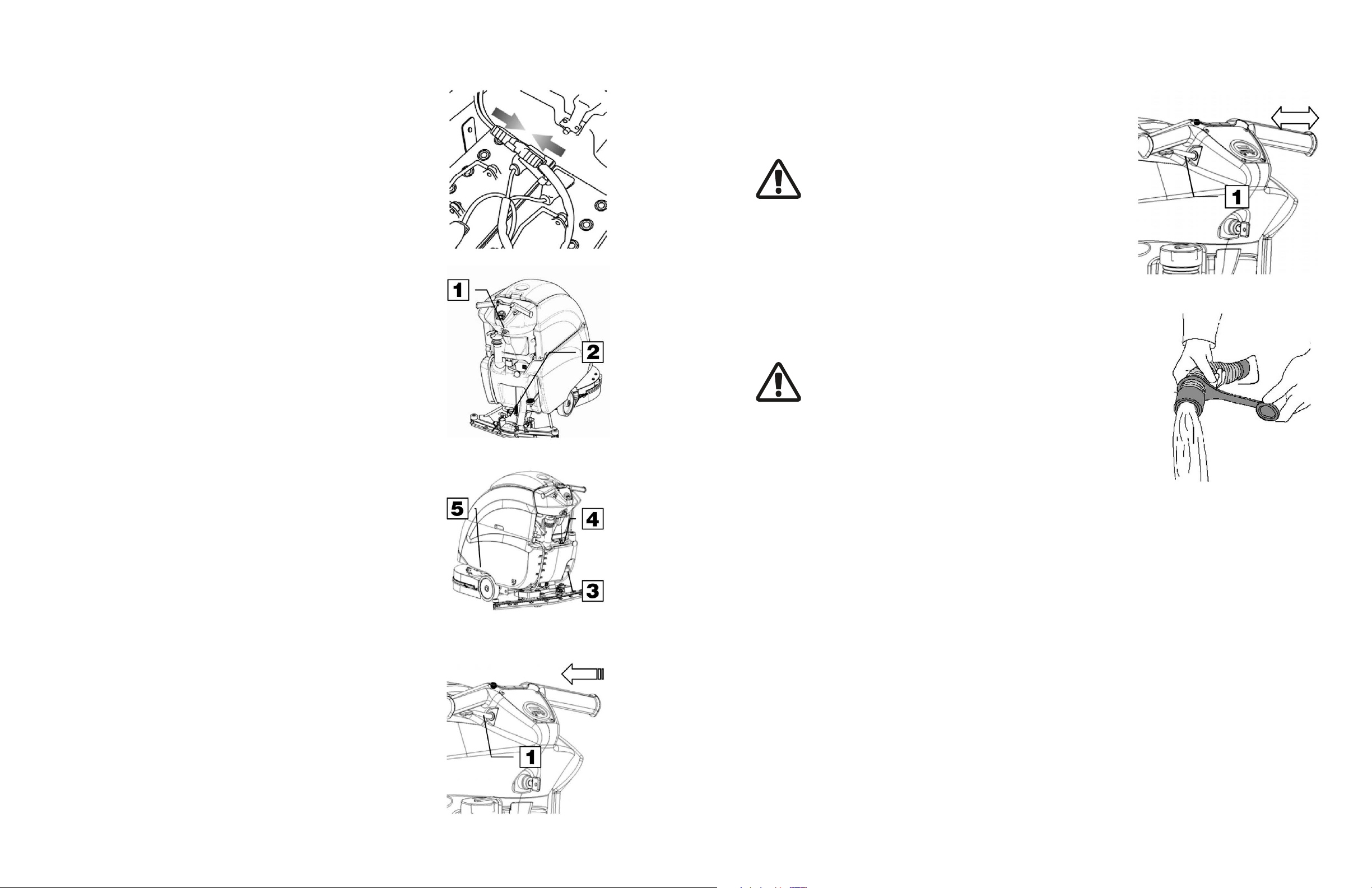
1. MACHINE OPERATION
A. Connect the battery plug to the machine plug.
B. Turn the key (1) of the main switch to the "ON" position (clockwise). The bat-
tery charge level indicator lights will immediately come on.
C. Turn on the water valve (2) (the water dispenses automatically when the pad
is oscillating).
2. REVERSE MOVEMENT
To move the machine in reverse push the switch levers (1) forward.
WARNING: When moving the machine in reverse, raise the
squeegee.
3. OVERFLOW DEVICE
The machine has a float in a filter basket that trips when the recovery tank is
full to stop airflow into the vacuum hose.
At this point empty the recovery tank by removing the cap of the drain hose.
WARNING: Always wear gloves when doing this
operation to protect yourself from contact with hazardous
chemicals.
D. Release the foot lever (3) and lower the pad deck.
E. Lower the squeegee by rotating the squeegee lift handle (4) counter clock-
wise. The vacuum motor will turn on.
F. Check that the brake (5) is released.
G. Pulling the switch levers (1), activates the pad and the machine begins to
move. During the first few feet, check that the amount of solution dispensed
is correct, and that the squeegee dries the floor.
H. The machine will now start to scrub and dry until the solution tank is empty
or recovery tank is full.
14 15
Page 9

SHUTTING DOWN THE MACHINE
DAILY MAINTENANCE
1. END OF WORK
When shutting down the machine and before you perform any type of maintenance:
A. Turn off the solution control valve (1)
B. Raise the pad deck using the foot pedal (2)
C. Raise the squeegee using the squeegee lift lever (3)
D. Turn off the key switch (4)
E. Move the machine where the tanks can be drained.
F. Remove the drain hose from it's hook, remove the drain cap and empty the
recovery tank.
G. The squeegee must be raised when the machine is not operating, to avoid
deforming the squeegee blades.
H. Remove any used pads and clean them with water.
WARNING: Always wear gloves when doing this operation to protect yourself from contact with hazardous chemicals.
1. CLEANING THE RECOVERY TANK
A. Raise the vacuum cover (1).
B. Remove the drain hose (2) from it's hook and empty the tank.
C. Rinse the inside of the tank with water.
D. Close the cover on the machine and replace the drain hose cap and drain
hose.
WARNING: Always wear gloves when doing this operation to protect yourself from contact with hazardous chemicals.
2. CLEANING THE VACUUM FILTER
A. Raise the cover.
B. Remove the vacuum filter cover by rotating it clockwise.
C. Pull the filter straight down from the lid to remove it.
D. Use water to clean the walls and base of the filter.
E. Reassemble all the components.
WARNING: Always wear gloves when doing this operation to protect yourself from contact with hazardous chemicals.
16 17
Page 10

DAILY MAINTENANCE
WEEKLY MAINTENANCE
3. CLEANING THE SQUEEGEE
To clean:
A. Take the machine to a safe location on flat ground and ensure that the device is in a safe condition.
B. Close the lid using the handle (1).
C. Secure the recovery tank latch (2).
D. Remove the vacuum hose (3) from the vacuum hose port (4).
E. Loosen the knobs (5) from the squeegee assembly and remove it from the machine.
F. Using a hose and cloth, thoroughly clean the squeegee assembly body (6).
G. Using a hose and cloth, thoroughly clean the front squeegee blade (7) and the rear squeegee blade (8).
H. Inspect the squeegee blades and replace them if the edges are worn.
I. Remove the vacuum hose port knobs (9) and clean inside the vacuum hose port (4) including the mating face on the squeegee assembly.
WARNING: Always wear gloves when doing this operation to protect yourself from contact with hazardous chemicals.
1. CLEANING THE SQUEEGEE HOSE
Every week, or whenever vacuum seems to be unsatisfactory, check the squeegee hose for obstructions. To clean it:
A. Remove the vacuum hose from the squeegee shoe adapter on the squeegee
shoe.
B. Wash the inside of the hose with water.
C. Drain and clean the recovery tank after cleaning the hose.
D. Reassemble the hose.
WARNING: Always wear gloves when doing this operation to protect yourself from contact with hazardous chemicals.
2. CHECKING THE BRAKE
Every week, check the distance between the work brake pads and the wheels. If
necessary, adjust so they are at a distance of 0.12 in (3 mm) when released.
4. REPLACING THE SQUEEGEE BLADES
Check the wear of the squeegee blades and, if necessary, replace them.
To replace them:
A. Follow the instructions in "Cleaning the Squeegee" section to remove the squeegee assembly.
B. Turn the wing nuts (1) that hold the front squeegee pressing blades (2) on the squeegee assembly.
C. Remove the front squeegee pressing blades (2) and the front squeegee (3) from the assembly.
D. Turn the wing nuts (4) that hold the rear squeegee pressing blades (5) on the squeegee assembly.
E. Remove the rear squeegee pressing blades (5) and the rear squeegee (6) from the assembly.
F. Reverse these instructions to reinstall the new squeegee blades.
WARNING: Always wear gloves when doing this operation to protect yourself from
contact with hazardous chemicals.
3. CLEANING THE SOLUTION TANK
A. Remove the solution tank cap.
B. Rinse with water.
C. Remove the drain cap (1) located on the filter, and empty the tank.
WARNING: Always wear gloves when doing this operation to protect yourself from contact with hazardous chemicals.
18 19
Page 11

TROUBLESHOOTING GUIDE
plug
INSUFFICIENT WATER ON THE PAD
1. Check water level in solution tank (1).
2. Check that the solution control valve (2) is rotated to the left.
3. Clean the solution tank filter (3) and inspect for blockages.
BATTERIES
MAINTENANCE SCHEDULE
Stealth ASDO20B
DAILY
Check water level - add if necessary DAILY
RECOMMENDED SERVICE
INTERVALS (HOURS)
50 100 200 400
THE MACHINE DOES NOT CLEAN WELL
1. Check the wear of the scrubbing pad and, if necessary, replace it.
THE SQUEEGEE DOES NOT DRY WELL
1. Check that the squeegee blades are clean.
2. Adjust the inclination of the squeegee.
3. Ensure the vacuum hose is correctly inserted in its housing in the recovery tank.
4. Disassemble the entire vacuum unit and clean it.
5. Replace the squeegee blades, if worn.
6. Check squeegee wheel adjustment.
TOO MUCH FOAM IS GENERATED
Check that low-foam detergent is being used. If necessary add a small amount of defoamer liquid to the recovery tank.
Remember that more foam is generated when the floors are not very dirty. Dilute the
detergent more when cleaning floors that are not very dirty.
CHOOSING AND USING THE PADS
RED SCRUBBING PAD - E89831
Used for general cleaning and scrubbing. It is capable of removing soil from the top of most hard surfaces. This pad is also
used to drive maroon pads and must be placed between the pad driver and maroon pad to avoid damage to the floor or the
machine.
MAROON STRIPPING PAD - E84057
The recommended pad for removing finishes from hard floors. It is also proficient at removing heavy soil and scuffs from concrete and epoxy coated floors. This pad must be used with a red pad between it and the pad driver.
GREEN TILE AND GROUT PAD - E84073
Used to clean tile floors, terrazzo, textured floors, and concrete.
WHITE POLISH PAD
Removes light soil and scuff marks from softer finishes. This pad is similar to the red pad but is less aggressive and will not dull
softer finishes such as wood floors.
ELECTRIC
SOLUTION TANK
RECOVERY TANK
ORBITAL HEAD
DECK MOTOR
VACUUM MOTOR
SQUEEGEE
Check cleanliness of machine battery
tray
Check tightness of electric contacts
and fuses
Check state of electric cables
crossing the machine
Check cleanliness of the tank
Check water valves and hoses to the
deck
Check all water connections from the
tank to the deck
Check cleanliness of the tank
Check filter and float system DAILY
sesoh niard dna muucav kcehC
Check vacuum gasket and drain
hose
Check state of bearing and isolators
Check pad locking face
Check wear of pad
Check cleanliness of air cooling inlet
Check noise level and cleanliness of
the inlet hose
Check vacuum performance, replace
if necessary
Check cleanliness of the squeegee
blades and shoe
Check wear of rear squeegee blade 50 100
Check wear of front squeegee blade 100 200
Check squeege structure and
machine support
s
DAILY
50
50
YLIAD
100
50
YLIAD
100
50
100
200
400
200
000,105sgulp dna snoitcennoc ,selbac kcehC
004YLIAD
000,1YLIAD
400 1,500
002
000,1004sehsurb nobrac kcehC
000,1level esion dna ward pma kcehC
004002sehsurb nobrac kcehC
1,000
004 elbac gnitfil dna revel kcehC
Suggested replacement
20 21
Page 12

Wear Items
WEAR ITEMS LISTING
Part # Description
E20060 Pad Driver
E20213 Isolator (10 per machine)
E22128 Bearing
E20215 Eccentric
E89831 Red Scrubbing Pad
E84057 Maroon Stripping Pad
E84073 Green Grout and Tile Pad
Part # Description
E22637 Squeegee Blade Kit, 31"
E84277 Squeegee Blade Kit, Poly, 31"
E84278 Squeegee Blade Kit, Latex, 31"
E11767 Battery 12V 130AH Wet
E88030 Battery 12V 110AH AGM
E86276 Battery 12V 115AH Wet
22 23
Page 13

12
34
41
18
28
29
27
16
40
38
17
11
8
44
13
17
23
10
17
18
ORBITAL DECK DRIVE DIAGRAM ORBITAL DECK DRIVE PARTS LISTING
Item# Part # Description Qty. Item# Part # Description Qty.
1 E20001 Spacer, 22 x 17 x 13 1
23
10
30
31
21
5.2
4
19
5.1
7
20
6
1517
33
35
24
2
10
17
43
35
26
3
14
42
2 E20048 Pipe 1
3 E20060 Pad Driver 1
4 E82576 Motor, Brush, 24VDC 400W 2300RPM 1
5 E82322 Solenoid Valve, 24v 10w 3-Port Nylon 1
5.1 E81794 Valve Body, Solenoid 1
5.2 E81795 Solenoid 1
6 E82399 Shaft Key 1
7 E83617 O-Ring, 14 x 2.5mm, Buna-N 1
8 E20082 Screw, M4 x 20 4
9 E22545 Screw 1
10 E83795 Bolt, Hex, M8 x 16, Zinc 16
11 E81917 Bolt, Hex, M8 x 20, Zinc 2
12 E83802 Bolt, Hex, M8 x 30, Zinc 3
13 E87285 Bolt, Hex, M8 x 50, Zinc 4
14 E22511 Screw, Flat Hd Soc Machine, M6 x 16 12
15 E81709 Nut, Nyloc Hex, M8, Zinc 7
16 E83859 Washer 4
17 E81874 Washer, Flat, M8 x 17 x 1.6, Zinc 22
18 E83404 Washer, Flat, M8 x 24 x 2, Zinc 6
19 E20253 Washer, Flat, M21 x 60 x 3, Zinc 1
20 E83882 Cap, 1/2" NPT 1
21 E20433 Nut, Hex Flange, M20, Plastic 1
22 E20323 Washer, Lock, M6, SS 1
23 E81046 Washer, Lock, M8 x 14.8 x 2, Zinc 16
24 E84264 Clamp, Hose 2
25 E22128 Bearing, 6206 2RSL/C3 1
26 E20577 Spacer 1
27 E20116 Spacer, 22 x 17.3 x 6 2
28 E22646 Cover, Wheel 2
29 E22668 Wheel, Bumper 2
30 E22641 Connector, Female 1
31 E84319 Molex Pin 2
32 E20153 Pin, Spring 1
33 E20169 Support 1
34 E20170 Bushing 3
35 E20213 Isolator 10
36 E20215 Eccentric 1
37 E20263 Bearing Retainer 1
38 E20280 Distributor 1
39 E20308 Washer 1
40 E20344 Cap 2
41 E20347 Washer 3
42 E20361 Screw, M8 x 14 4
43 E20410 Base 1
44 E20423 Weight 3
14
1
36
32
37
25
39
22
9
24 25
Page 14

SQUEEGEE ASSEMBLY DIAGRAM SQUEEGEE ASSEMBLY PARTS LISTING
Item# Part # Description Qty. Item# Part # Description Qty.
1 E84336 Mounting Stud 2
3 E22637 Squeegee Blade Kit, 31" 1
4 E84277 Squeegee Blade Kit, Poly, 31" 1
5 E84278 Squeegee Blade Kit, Latex, 31" 1
15
24
20
22
19
15
24
22
6 E84337 Squeegee Assembly Complete, 31.5" 1
7 E83331 Knob, M8 Round Nylon Female 2
8 E83402 Spring, 15mm O.D. x 11mm I.D. x 16mm L 2
9 E83804 Stud 2
27
28
10
9
16
2
18
21
24
15
11
7
8
12
1
26
23
25
20
15
24
22
10 E84338 Spacer 2
11 E81342 Nut, Hex Jam, Nyloc, M8 SS 2
12 E86164 Flat Washer M9x24x2.5 SS 2
15 E22346 Screw, Custom Cap 18
16 E22633 Squeegee Body 1
17 E22352 Center Front Squeegee Blade Clamp 1
18 E22635 Clamp, Front Squeegee Blade 2
19 E22355 Center Rear Squeegee Blade Clamp 1
20 E22634 Rear Squeegee Blade Clamp 2
21 E22358 Wing Nut Knob 9
22 E22359 Wing Nut Knob 9
23 E22360 Squeegee Shoe Adapter 1
24 E22385 O-Ring, 7mm 36
25A E22637 Squeegee Blade Kit, 31" 1
25B E84277 Squeegee Blade Kit, Poly, 31" 1
25C E84278 Squeegee Blade Kit, Latex, 31" 1
26 E22630 Thumb Screw 2
27 E22646 Wheel Cover 2
28 E22668 Bumper Wheel 2
3
4
5
18
21
17
24
21
15
24
15
800
6
26 27
Page 15

35
39
31
SQUEEGEE YOKE DIAGRAM SQUEEGEE YOKE PARTS LISTING
Item# Part # Description Qty. Item# Part # Description Qty.
1 E20006 Bushing 1
2 E88279 Micro Switch Sealed 1
3 E20408 Squeegee Lift Lever 1
4 E84339 Sheath 1
15
26
15
26
19
33
3
12
22
36
34
32
17
18
2
9
18
28
5
29
4
20
6
11
5 E84340 Squeegee Lift Chain 1
6 E83331 Knob, M8 Round Nylon Female 2
7 E20078 Squeegee Wheel Support 2
8 E20079 Threaded Adjuster Rod 2
9 E22671 Bolt, M6 x 25 1
10 E82274 Bushing 2
11 E20091 Spring 2
12 E82288 Screw, Pan Hd Phil, Self Tap, M5.2 x 20, Zinc 4
13 E83933 Screw, Tripla Side Squeegee 2
14 E83833 Hex Bolt M8x25 Zinc 1
15 E20287 Hex Bolt M8x45 SS 2
16 E20099 Hex Bolt M8x80 SS 1
17 E20242 Pan Hd Phil Machine Screw M3x20 Zinc 2
18 E82317 Hex Jam Nut, M5X3.5 Zinc 2
19 E20113 Hex Jam Nut, M6X4 SS 1
20 E83672 Hex Jam Nut, M8x5 SS 2
40
1
8
21 E83824 Square Nut, M8 SS 2
22 E81673 Nut, Hex Nyloc, M3 Zinc 2
23 E81342 Nut, Hex Jam, Nyloc, M8 SS 2
24 E20119 Nyloc Hex Nut, M8 SS 1
25 E81046 Lock Washer M8 Zinc 1
26 E86164 Flat Washer M9x24x2.5 SS 4
27 E86147 Split Pin 1
28 E83538 Fork 1
29 E83542 Clip 1
30 E82314 Nut, Hex Jam, Nyloc, M6, SS 2
31 E20519 Spring 1
32 E82256 Nyloc Hex Nut, M5x7 Zinc 1
33 E20638 Knob 1
34 E84341 Cam Guard 1
35 E84342 Squeegee Carriage 1
36 E84343 Lift Coupling 1
37 E84344 Squeegee Support Wheel 2
38 E84345 Pivot Plate 1
39 E84346 Spacer 1
40 E84347 Spacer 1
38
24
21
27
7
25
26
23
30
37
13
10
14
16
28 29
Page 16

MAIN FRAME DIAGRAM MAIN FRAME PARTS LISTING
Item# Part # Description Qty. Item# Part # Description Qty.
1 E88253 Bushing 4
2 E20006 Bushing 1
3 E83597 Brush Deck Lift Idler Arm Weldment 1
16
4
25
20
38
34
40
4 E20370 Foot Pedal 1
5 E20609 Bearing Mount Base 2
6 E20014 Bearing Mount Cap 2
7 E20473 Switch Plate 1
8 E20315 Shim Plate 2
9 E20446 Axle Shaft, Right 1
3
15
29
25
28
36
43
10 E20458 Axle Shaft, Left 1
11 E20071 Clamp Plate 1
38
39
12 E88256 Micro Switch 1
13 E20388 Brush Deck Lift Arm Weldment 1
29
31
15
31
29
23
12
15
7
15
13
24
15
31
29
11
42
24
27
18
2
40
35
21
14 E20582 Drive Motor 24VDC 150W 1
14.1.1 E20523 Carbon Brush 2
15 E82834 Pivot Block 6
16 E83669 Pedal cover 1
17 E81657 Bearing, 6204 2RS 2
18 E20356 Carriage Bolt M6x20 Zinc 1
19 E88888 Hex Bolt, M6 x 40, Zinc 4
20 E83833 Hex Bolt M8x25 Zinc 1
21 E81735 Hex Bolt M12x35 Zinc 2
22 E83578 Soc Hd Cap Screw M6x25 Zinc 2
23 E20242 Pan Hd Phil Machine Screw M3x20 Zinc 2
24 E20108 Screw, Pan Hd Phil Self Tap M4.8x16 SS 2
25 E20246 Flat Hd Soc Machine Screw M6x50 Zinc 2
26 E22002 Screw, M8 x 30 2
27 E83852 Nut, Hex, M8, Zinc 1
28 E83829 Hex Jam Nut, M12X7 Zinc 2
29 E83550 NyLoc Hex Nut, M6 Zinc 10
30 E86853 Nyloc Hex Nut, M8 Zinc 4
31 E82761 Flat Washer M6x12x1.6 Zinc 10
32 E88585 Washer, Flat, M6 x 18, Zinc 2
33 E88594 Washer, Split Lock, M6, Zinc 2
34 E81046 Lock Washer M8 Zinc 1
35 E82773 Flat Washer M10x21x2 Zinc 2
36 E81738 Flat Washer M4x12x3 Zinc 2
37 E84333 Bearing Washer 2
38 E20255 Flat Hd Soc Machine Screw M6x45 Zinc 4
39 E20435 Nyloc Hex Nut, M3 SS 2
40 E20437 Castor 2
41 E20591 Carriage Bolt M8x100 Zinc 4
42 E20501 Splash Guard 1
43 E20369 Parking Brake 1
44 E84334 Wheel 2
45 E84335 Spacer 2
46 E84331 Chassis 1
30 31
Page 17

37
44
26
TRANSAXLE DIAGRAM TRANSAXLE PARTS LISTING
Item# Part # Description Qty. Item# Part # Description Qty.
1 E88253 Bushing 4
2 E20006 Bushing 1
3 E83597 Brush Deck Lift Idler Arm Weldment 1
41
46
45
19
31
8
5
9
17
6
1
30
32
29
8
14
14.1.1
1
30
31
33
19
10
45
44
37
26
5
17
6
22
4 E20370 Foot Pedal 1
5 E20609 Bearing Mount Base 2
6 E20014 Bearing Mount Cap 2
7 E20473 Switch Plate 1
8 E20315 Shim Plate 2
9 E20446 Axle Shaft, Right 1
10 E20458 Axle Shaft, Left 1
11 E20071 Clamp Plate 1
12 E88256 Micro Switch 1
13 E20388 Brush Deck Lift Arm Weldment 1
14 E20582 Drive Motor 24VDC 150W 1
14.1.1 E20523 Carbon Brush 2
15 E82834 Pivot Block 6
16 E83669 Pedal cover 1
17 E81657 Bearing, 6204 2RS 2
18 E20356 Carriage Bolt M6x20 Zinc 1
19 E88888 Hex Bolt, M6 x 40, Zinc 4
20 E83833 Hex Bolt M8x25 Zinc 1
21 E81735 Hex Bolt M12x35 Zinc 2
22 E83578 Soc Hd Cap Screw M6x25 Zinc 2
23 E20242 Pan Hd Phil Machine Screw M3x20 Zinc 2
24 E20108 Screw, Pan Hd Phil Self Tap M4.8x16 SS 2
25 E20246 Flat Hd Soc Machine Screw M6x50 Zinc 2
26 E22002 Screw, M8 x 30 2
27 E83852 Nut, Hex, M8, Zinc 1
28 E83829 Hex Jam Nut, M12X7 Zinc 2
29 E83550 NyLoc Hex Nut, M6 Zinc 10
30 E86853 Nyloc Hex Nut, M8 Zinc 4
31 E82761 Flat Washer M6x12x1.6 Zinc 10
32 E88585 Washer, Flat, M6 x 18, Zinc 2
33 E88594 Washer, Split Lock, M6, Zinc 2
34 E81046 Lock Washer M8 Zinc 1
35 E82773 Flat Washer M10x21x2 Zinc 2
36 E81738 Flat Washer M4x12x3 Zinc 2
37 E84333 Bearing Washer 2
38 E20255 Flat Hd Soc Machine Screw M6x45 Zinc 4
39 E20435 Nyloc Hex Nut, M3 SS 2
40 E20437 Castor 2
41 E20591 Carriage Bolt M8x100 Zinc 4
42 E20501 Splash Guard 1
43 E20369 Parking Brake 1
44 E84334 Wheel 2
45 E84335 Spacer 2
46 E84331 Chassis 1
32 33
Page 18

19
1.12
1.11
1.19
1.4
1.17.2
1.7
1.17.3
1.17.2
1.17.3
1.1
SOLUTION TANK DIAGRAM
8
13
11
18
6
17
4
9
15
9
7
1.2
1.14
1.8
1.3
1.18
1.5
1.6
1.17.1
1.17
16
SOLUTION TANK PARTS LISTING
Item# Part # Description Qty. Item# Part # Description Qty.
1 E20285 Solution Tank ASM 1
1.1 E88258 Hose, Glass Reinforced 15 OD x 10 ID x 496 L 1
1.2 E20409 Foot Pedal Latch Plate 1
1.3 E20611 Guard Plate 1
1.4 E86145 Knob 1
1.5 E82429 Cap 1
1.6 E82612 Filter 1
1.7 E20107 Screw, Pan Hd Phil Self Tap M4.2x16 SS 2
1.8 E20110 Flat Hd Soc Machine Screw M5x25 SS 2
1.9 E20122 Flat Washer M5 x 15 x 1.5 SS 1
1.10 E85762 Hose Clamp 1
1.11 E83361 Ball Valve 1
1.12 E83943 Nipple, Double Female 3/8" 1
1.13 E81981 Spacer 1
1.14 E20468 Flat Hd Phil Machine Screw M5x12 Zinc 3
1.15 E88259 Filter, Water 23 x 53 Plug 3/4" 1
1.16 E88261 Flat Washer M8.2x32x4 Zinc 1
1.17 E20197 Solution Tank, Gray 1
1.17.1 E20389 Hinge Pin 1
1.17.2 E20271 Grommet 2
1.17.3 E20196 Fitting, Barbed 2
5
1.18 E20577 Spacer 1
1.19 E20602 Fitting, Barbed Threaded 1
2 E20411 Bracket 1
3 E82772 Hex Bolt M6x20 Zinc 2
4 E20090 Hex Bolt M6x25 Zinc 3
5 E20392 Pan Hd Phil Machine Screw M4x16 Zinc 4
6 E83796 Screw, Pan Hd Phil Self Tap M4.2x16 Zinc 5
7 E20112 Hex Nut, M6x6 Zinc 1
8 E20121 Flat Washer M5x15x1.5 Zinc 2
9 E82798 Washer, 6x18x1.5 6
10 E82774 Lock Washer, M6 Zinc 4
11 E20708 Cover, Bolt 2
12 E81619 Support Bracket 1
13 E20359 Hex Bolt M5x30 Zinc 2
14 E20468 Flat Hd Phil Machine Screw M5x12 Zinc 1
15 E88260 Lanyard 1
16 E20438 Bezel 1
17 E20709 Battery Tray 1
18 E20710 Housing, Plastic 1
19 E20711 Housing Cover, Plastic 1
4
14
12
9
10
2
3
1.15
1.16
10
9
34 35
Page 19

RECOVERY TANK DIAGRAM
RECOVERY TANK PARTS LISTING
Item# Part # Description Qty. Item# Part # Description Qty.
1 E88499 Hose, Vacuum 1
2 E20074 Hinge Pin 1
15
14
3.1
3.10
3.2
3.3
3.11.2
1
12
3 E20354 Recovery Tank ASM 1
3.1 E20189 Fitting, Barbed 1
3.2 E20186 Elbow 1
3.3 E88285 Filter, Cage 1
3.4 E88286 Hose, Drain 1
3.5 E12633 Latch 1
3.6 E20107 Screw, Pan Hd Phil Self Tap M4.2x16 SS 2
3.7 E20707 Clamp, Hose M40-64 Zinc 1
3.8 E20468 Flat Hd Phil Machine Screw M5x12 Zinc 3
3.9 E81619 Cable Tie Holder 3
3.10 E82341 Gasket 1
3.11.1 E20198 Recovery Tank, Red 1
3.11.2 E20188 Hinge Pin 1
4 E83833 Hex Bolt M8x25 Zinc 1
5 E82638 Screw, Pan Hd Phil Self Tap M3.9x13 SS 6
6 E82808 Hex Jam Nut, M8X5 Zinc 1
7 E20127 Flat Washer M9x18x1.5 Zinc 1
8 E20563 Plate 1
9 E20195 Plate 1
10 E20524 Spacer, Nylon 1
11 E88500 Fitting, Hose D38, W1.5, L50 1
12 E83920 Clamp 9x300 4,8x360 black 2
13 E88499 Hose, Vacuum 1
14 E22072 Bale, Vac Lid 1
15 E22074 Plug, Vac Lid Bale 2
3.11.1
3.6
3.5
3.4
3.7
11
12
13
9
5
4
7
6
2
10
8
3.9
3.8
5
36 37
Page 20

VACUUM UNIT DIAGRAM
VACUUM UNIT PARTS LISTING
Item# Part # Description Qty. Item# Part # Description Qty.
1 E20265 Plate 2
2 E20066 Recovery Tank Cover ASM 1
2.27
2.8 2.19
2.1 E20305 Mounting Ring 1
2.2 E20652 Sound Deadening Foam 1
2.11
2.3 E20180 Sound Deadening Foam 1
2.4 E20179 Sound Deadening Foam 1
2.13
2.26
2.23
2.9
2.18
2.10
4
2.22
2.28
2.12
2.25
5
6
2.7
2.1
2.26
2.21
2.5
2.14
2.3
2.17
2.16
2.4
2.6
2.30
2.29
1
3
2.20.4
2.15
2.24
2.2
2.20.2
2.20.1
2.20.3
2.5 E20178 Sound Deadening Foam 1
2.6 E20266 Sound Deadening Foam 1
2.7 E88292 Filter, Cage 1
2.8 E20486 Bushing 1
2.9 E20384 Vacuum Motor Cover 1
2.10 E20191 Deflector 1
2.11 E20199 Recovery Tank Cover 1
2.12 E81710 Hose Clamp 1
2.13 E20325 Hose Clamp 2
2.14 E20181 Sound Deadening Foam 1
2.15 E20184 Sound Deadening Foam 1
2.16 E20183 Sound Deadening Foam 1
2.17 E20182 Sound Deadening Foam 1
2.18 E88289 Gasket 1
2.20
2.19 E20064 Support Bracket 1
2.20 E88291 Vacuum Motor 24VDC 310W 1
2.20.1 E83897 Connector, Electrical Housing 30A 2
2.20.2 E83883 Lug, Electrical 30A 2
2.20.3 E83935 Wire Tie 2
2.20.4 E22324 Carbon Brush 2
2.21 E81006 Vacuum Splash Guard 1
2.22 E20122 Flat Washer M5 x 15 x 1.5 SS 5
2.23 E88290 Hose, Vacuum 1
2.24 E20440 Sound Deadening Foam 1
2.25 E83796 Screw, Pan Hd Phil Self Tap M4.2x16 Zinc 2
2.26 E83838 Screw, Flat Hd M4x15 Zinc 2
2.27 E20442 Button Hd Soc Machine Screw M5x16 Zinc 1
2.28 E20084 Hex Bolt M5x16 SS 5
2.29 E20712 Magnet 1
2.30 E20192 CHIPBOARD SCREW M3x12 Zinc 1
3 E20107 Screw, Pan Hd Phil Self Tap M4.2x16 SS 4
4 E20298 Soc Button Head Screw M5x16 SS 1
5 E22075 Hook, Vac Lid Bale 1
6 E22076 Screw, M4 x 10 2
38 39
Page 21

SOLUTION DELIVERY DIAGRAM
SOLUTION DELIVERY PARTS LISTING
Item# Part # Description Qty. Item# Part # Description Qty.
1 E81035 Solenoid Valve 1
2 E85762 Hose Clamp 4
8
7
1
2
4
2
3 E22144 Tubing, 10 ID x 370 L 1
4 E20375 Tubing, 10 ID x 650 L 1
5 E20602 Fitting, Threaded Barb 1
7 E22145 Fitting, 3/8" - 1/4" Reducer 1
8 E88829 Fitting, 90 Degree Elbow 1
5
2
2
3
40 41
Page 22

1.45
1.47
1.44
1.19
1.28
1.13
1.9
1.15
1.38
1.27
1.26
1.35
1.34
1.39
HANDLEBAR DIAGRAM
HANDLEBAR PARTS LISTING
Item# Part # Description Qty. Item# Part # Description Qty.
1.1 E20330 Ball Stud M10x22.5 2
1.37
1.14
1.46
1.2 E20574 Bushing 1
1.3 E82351 Key Switch Assembly w/Keys 1
1.3 .1 E83173 Contact, Key Switch 1
1.40
1.36
1.3.2 E83316 Key Switch 1
1.3.3 E81358 Switch Flange 1
1.3.4 E83315 Switch Key (1) 1
3
1.4 E22079 Plate, Electrical Panel 1
1.5 E81763 Cam 1
1.38
1.32
1.3.1
1.43
1.41
1.17
1.23
1.22
1.12
4
5
1.29
2
1.3.3
1.3.4
1.6
1.3.2
1.20
1.8
1.16
1.1
1.7
1.4
1.5
1.21
1.18
1.30
1.42
1.15
1.29
1.11
1.24
1.10
1.17
1.2
1.22
1.12
1.1
1.31
1.17
1.33
1.25
1.16
1.23
1.6 E83836 Hex Bolt M5x16 Zinc 1
1.7 E82304 Spring, 20.2x1.3x20.8mm Steel Torsion 1
1.8 E83851 Screw, Pan Hd Phil Self Tap, M5.5x13, SS 2
1.9 E84348 Screw, M4 x 25 Zinc 1
1.1 E20341 Hex Bolt M4x16 Zinc 1
1.11 E84349 Bolt, M3 x 16 2
1.12 E20242 Pan Hd Phil Machine Screw M3x20 Zinc 4
1.13 E20392 Pan Hd Phil Machine Screw M4x16 Zinc 4
1.14 E83899 Screw, Machine, Pan Hd Phil, M5x10, SS 6
1.15 E20248 Hex Nut, M4x4 Zinc 2
1.16 E82317 Hex Jam Nut, M5X3.5 Zinc 2
1.17 E81673 Nut, Hex Nyloc, M3 Zinc 6
1.18 E83550 NyLoc Hex Nut, M6 Zinc 1
1.19 E20292 Flat Washer M4x9x0.8 Zinc 4
1.2 E20121 Flat Washer M5x15x1.5 Zinc 1
1.21 E88585 Washer, Flat, M6 x 18, Zinc 1
1.22 E82270 Micro Switch 2
1.23 E81625 Shank, M5x32 Female Threaded Nylon 2
1.24 E20360 Hex Bolt M6x45 Zinc 1
1.25 E20362 Set Screw Hex Soc Dog Point M5x30 Zinc 1
1.26 E20298 Soc Button Head Screw M5x16 SS 1
1.27 E81978 Nut 1
1.28 E20475 Lock Washer M4 Zinc 4
1.29 E82256 Nyloc Hex Nut, M5x7 Zinc 2
1.3 E88300 Lever, Left Switch 1
1.31 E88301 Lever, Right Switch 1
1.32 E20267 Door 1
1.33 E88267 Switch Cam 1
1.34 E20400 Hinge 1
1.35 E20192 Screw, Chipboard, M3x12 Zinc 4
1.36 E20713 Potentiometer 1
1.37 E84350 Push Button 1
1.38 E22619 Nut 2
1.39 E22082 Lower Handle Bar 1
1.4 E22083 Upper Handle Bar 1
1.41 E22084 Cap, Handle Bar 2
1.42 E22085 Hinge Pin 1
1.43 E22620 Hose Clip 1
1.44 E84351 Control Card 1
1.45 E84352 Plate 1
1.46 E84353 Battery Discharge Indicator 1
1.47 E84354 Speed Control Knob 1
2 E20288 Soc Hd Cap Screw M8x30 Zinc 4
3 E20346 Screw, Flat Hd Soc Machine, M8x25, SS 2
4 E81874 Flat Washer M8x17x1.6 Zinc 4
5 E81046 Washer, Lock, M8, Zinc 4
6 E89890 Battery Cable w/ 80Amp Fuse 1
42 43
Page 23

ELECTRICAL DIAGRAM ELECTRICAL PARTS LISTING
Item# Part # Description Qty. Item# Part # Description Qty.
1 Various Batteries 2
2 Various Battery Charger 1
3 Fuse 1
4 E83316 Key Switch 1
5 E84353 Battery Discharge Indicator 1
6 E88279 Microswitch Vacuum Motor 1
7 E82270 Microswitch Forward 1
8 E82270 Microswitch Reverse 1
9 E88256 Microswitch Brush Motor 1
10 E84350 Push Button 1
11 E20713 Potentiometer 1
12 N/A Dilution Control Commutator Card (Not Used) 0
13 N/A Dilution Control Card (Not Used) 0
14 E81035 Solenoid Valve 1
15 E84351 Control Card 1
F2 E89890 Fuse 80A 1
MT E20582 Traction Motor 1
MBR E84328 Brush Motor 1
MVA E88291 Vacuum Motor 24VDC 310W 1
44 45
Page 24

BATTERY CHECK CARD / HOUR METER
1. Verify that when turning on the machine, the battery discharge indicator
has the following starting sequence:
SOLUTION TANK INSPECTIONS
• For the first 2 seconds, display the setting
of the dip switches.
• Then display the total worked hours and
level of residual charge of the battery.
During the first 2 seconds, the value displayed on the left indicates the
rated voltage set for the battery discharge indicator. The value on the right
indicates the low voltage shutoff threshold.
For Wet Cell batteries, the low voltage shutoff should be equal to 20.2V.
For Gel or AGM batteries, the low voltage shutoff shoudl be equal to 21.8V.
2. The battery discharge indicator should be adjusted
according to the type of batteries that are installed in the
machine. To change the settings, simply adjust the dip
switches located on the back of the device.
The grid below shows the proper settings for each
battery type.
1. Fill up the solution tank and verify the sealing of the gasket particularly
on the solution valve and on the drain plug.
2. Verify that the water distribution on the floor is even and dependent on
the solution valve adjustment.
3. Check the internal cleanness of the water valve. If necessary clean it using a metal bar putted inside the threaded hole of the filter plug.
4. Verify the cleanness and functionality of the solution filter under the
solution tank plug.
VACUUM SYSTEM INSPECTIONS
1. Verify the cleanness and functionality of the float filter.
2. Check the air sealing of the vacuum unit on the recovery tank.
3. Verify the connections and the sealing of the vacuum hoses and the
squeegee hoses.
4. Check the sealing of the squeegee hose adapter.
5. Check the sealing of the exhaust hose and exhaust hose plug.
Hour meter Dip Switch Settings
1 2 3 4 5 6 Setup
OFF ON OFF OFF OFF OFF Wet Cell
OFF ON ON OFF OFF OFF GEL / AGM
46 47
6. Vacuum micro switch adjustment:
7. Adjust the vacuum micro switch in way that when the cam on the
squeegee lever push the micro switch there is about 0.5 mm of clearance of the micro switch lever.
Page 25

BRAKE ADJUSTMENT
1. Verify that the brake on the left hand wheel locks the wheel when active.
2. Otherwise adjust as follows:
• Unscrew the jam nut.
• Loosen the pad screw to achieve the right adjustment.
• Verify the adjustment with a functional test
• Tighten the jam nut to assure a right adjustment.
CHECK LIST
Functional check of the machine
Check the functionality of switches.
Check the functionality of the switch lever.
Check the functionality of the orbital deck.
Check the functionality of the deck motor.
Check the functionality of the solenoid valve.
Check the functionality of the vacuum motor.
Check the functionality of the brakes.
Check the functionality of batteries and power cables.
SQUEEGEE ADJUSTMENT
1. Adjust the inclination adjuster of the squeegee blade until the blade has a
common inclination over its entire length.
2. Adjust the height of the wheels using the knob checking that the blade has an
inclination between 30 and 45 degrees.
3. Verify the cleanliness and sealing of the squeegee hose adapter.
Functional test of the machine
Fill up the tanks completely and verify the sealing.
Verify the sealing of all the water fitments and that the water is dispensed to the deck.
Adjust the inclination and the height of the squeegee blades doing a functional test.
Check the efficiency of the parking brake.
Verify the forward and backward movement, acceleration and braking.
Final test
Check all the functions: washing, drying and movement.
48 49
Page 26

50 51
Page 27

BETCO US WARRANTY POLICY
10 year coverage
Subject to the conditions stated below,
Betco warrants parts and labor on
rotationally molded polyethylene tanks/
housings and injection molded vacuum
head assemblies to be free from defects
in materials and workmanship for
a period of ten years to the original
purchaser.
Allowable Travel Time Warranty Reimbursement:
Eligible equipment: All battery and propane powered equipment products. Warranty period: 90 days from date of sale to the
original purchaser. A maximum 180 mile round trip at 50 cents per mile will be allowed for warranty consideration.
3 Year Coverage
Subject to the conditions stated below,
Betco warrants parts and labor on all
other Betco components to be free from
defects in materials and workmanship
for a period of three years to the
original purchaser.
• Lithium Ion battery for MotoMop™ is
a full 3 years
1 Year Coverage
Subject to the conditions stated below,
Betco offers a limited warranty on parts
and labor on the following equipment:
parts and accessories to be free from
defects in materials and workmanship
for a period of one year to the original
purchaser.
• PowerUp™ 14 Upright Vacuum:
#E29990-00
• Bac Pac Lite Vacuum: #85903-00
• FiberPRO® Floor Dryer: #85507-00
• WORKMAN™ Series Vacuums:
#85024-00, #85025-00, #83012-00,
#85027-00
• All Tools and Accessories
• All Battery Chargers
• Deep cycle batteries are pro-rated for
1 year
Propane Machine Warranty:
Kawasaki engines are warranted by Kawasaki for a period of 2 years against manufacturer defects. All other components
(except wear items)* are warranted by Betco for a period of 3 years.
*Wear Items exempt from Warranty consideration include but may not be limited to: power cords, transport wheels,
vacuum bags, belts, squeegee blades, pad drivers, clutch plates, handle grips, filters, screens, throttle cables, brushes
and carbon brushes.
Subject to the conditions and exceptions stated in this warranty, Betco warrants the Betco products to be free from defects
in material and workmanship, under normal use and service, for the periods listed under the warranty policy to the original
purchaser. At any time during the warranty period, Betco will furnish replacement parts for the Betco parts to the original
purchaser. Such parts will be furnished and charged including transportation costs, to the original owner through any Betco
authorized Service Distributor. If the original part is returned within the warranty policy period from date of delivery for
inspection by Betco and is found to be defective the owner will be credited for the cost of replacement parts plus shipping and
handling. Replacement parts that have become defective through wear or abuse are not included in this warranty.
This warranty does not apply to damage or defect caused by accident, misuse. Negligence, fire, or to any Betco product which
has been serviced or repaired by other than an authorized Betco Service Distributor or Betco factory personnel. This warranty
is void if products are used for any purpose other than that which was intended. There are no other warranties expressed or
implied. In no event shall Betco be liable for incidental or consequential damages or any damage to person or property. (Please
note some states do not allow the exclusion or limitations for incidental and consequential damages).
52
Customer Service: 888-GO-BETCO • Fax: 800-445-5056 • Technical Service: 877-856-5954 • www.betco.com
400 Van Camp Road • Bowling Green, Ohio 43402
91718-92 Feb19A
 Loading...