

Page 1
E12327-00
™
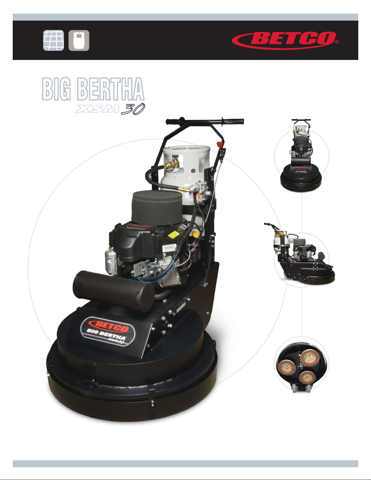
BIG BERTHA
X
XS
S
M
M
30
30" Extreme Strip
and Scrub Machine
Operator and Parts
Manual
1001 Brown Avenue • Toledo, Ohio 43607-0127
Customer Service: 888-GO-BETCO • Fax: 800-445-5056 • Technical Service: 877-856-5954 • www.betco.com
1
Page 2

TABLE OF CONTENTS
CARBON MONOXIDE WARNING ...................................... 3
SAFETY ............................................................................ 4
TANK USE AND STORAGE ...............................................5
STARTING AND STOPPING THE HONDA ENGINE ............ 5
OPERATOR PREPARATION ..............................................6
MAJOR ASSEMBLIES ......................................................7
HANDLE BAR ..............................................................8 - 9
LOWER HANDLE SUPPORT ....................................10 - 13
REGULATOR ASSEMBLY ........................................14 - 15
12V STARTER SWITCH ...........................................14 - 15
KAWASAKI ENGINE ASSEMBLY ..............................16 - 17
DECK ASSEMBLY ....................................................18 - 19
MAIN DRIVE SYSTEM .............................................20 - 21
PIVOT BRACKET ASSEMBLY ..................................22 - 25
BRUSH PLATE ASSEMBLY ......................................26 - 27
ENGINE MAINTENANCE ................................................. 28
ELECTRICAL SCHEMATIC .............................................. 29
MAIN DRIVE BELT .........................................................30
BRUSH DRIVE PLATE AND BELT ...................................31
BRUSH CHANGE ............................................................ 32
TROUBLESHOOTING .....................................................33
EMISSIONS WARRANTY ........................................34 - 35
WARRANTY.................................................................... 36
2
Page 3

WARNING - CARBON MONOXIDE
LETHAL EXHAUST GAS
- MUST READ THIS! -
Never Run The Engine In A Closed Building Or Confined Area
Exhaust gases contain poisonous carbon monoxide.
Carbon monoxide is odorless, colorless, and can cause death if inhaled.
Carbon Monoxide Poisoning Symptoms
Train your employees to know the warning signs of carbon monoxide poisoning.
Mild carbon monoxide poisoning may cause any of the following:
Headache, drowsiness, faintness, poor coordination, nausea, and vomiting.
Turn the engine off and immediately get to fresh air if you have any of these symptoms.
Do not run the machine until it is given an emissions test and repairs made by an authorized distributor.
• Local emissions testing is available at a fork-lift service department.
Moderate or severe carbon monoxide poisoning causes confusion, unconsciousness, chest pain, shortness of breath, and
coma. Thus, most victims are not able to move themselves and must be rescued. Severe poisoning is often fatal.
Carbon monoxide is dangerous because a person may not recognize drowsiness as a symptom of poisoning. Consequently,
someone with mild poisoning can go to sleep and continue to breathe the carbon monoxide until severe poisoning or death
occurs. Some people with long-standing, mild carbon monoxide poisoning caused by furnaces or
heaters may mistake their symptoms for other conditions, such as the flu or other viral infections.
Carbon Monoxide Detectors
CO detectors are a must for safe operation of your equipment. Various types are available. A “CO” carbon monoxide detector
detects carbon monoxide before it reaches dangerous levels. Detectors are a must for those who run propane powered
equipment. The CO Detector is for everyone’s protection against Carbon Monoxide Poisoning.
• Carbon Monoxide Detector - Passive
– Effective for 30 days after package has been opened.
– Write the date opened on the detector.
– Mount with self-adhesive strip on the machine handle.
– Train machine operator to check detector regularly.
– If the orange disk changes to gray or black - your Carbon Monoxide Levels are
at a Dangerous Level.
– If the orange disk changes to gray or black you must turn your buffer off immediately and return it to your nearest
authorized distributor for an emissions test.
– Do Not Restart the machine until the emissions have been checked and corrected.
– This is for your protection as well as your customers. CO detectors are a must for safe operation and maximum
efficiency of your equipment.
– For replacement CO detectors, contact your distributor. Ask for the carbon monoxide detector,
part# E012426.
• Carbon Monoxide Detector - battery operated with alarm
– Available from various sources
3
Page 4

SAFETY
lmportant Safety Information
All LPG (Liquid Propane Gas) powered engines, including this engine, produce Carbon Monoxide (CO). It is a
Lethal Poison that is colorless, odorless, tasteless, and non-irritating gas. You must read “Danger: Lethal Exhaust Gas”
information below.
Keep hands, feet, and loose clothing away from all moving parts while the machine is in operation. The exhaust system
gets very hot so keep hands, clothing and any items that can burn away from the engine, engine manifold, and muffler.
These machines are tough and durable, however do not abuse the machine. With proper care and maintenance this unit
will give you years of trouble free operation.
Carbon Monoxide Safety Information
Engine exhaust gases contain poisonous carbon monoxide. Carbon monoxide is odorless, colorless, tasteless, and
can cause death if inhaled. Failure to provide proper venting of CO, failure to properly maintain the engine, or failure to
properly train personnel of the dangers and warning signs of carbon monoxide exposure may result in Serious Injury Or
Death to the operator and others in the area.
• Any equipment with the potential to produce carbon monoxide presents a significant hazard when used indoors.
They must be used with great caution. Opening a door or window, or running an exhaust fan will not necessarily
supply adequate ventilation. Avoid inhaling exhaust fumes and never run the engine in a closed building or
confined area without proper ventilation.
• Do not allow engine to run unattended.
• If you have any indication that the engine is not running properly, immediately shut the machine off and have it
checked over and repaired by qualified maintenance personnel.
• Workers should be trained to recognize the hazards of carbon monoxide and the early symptoms of carbon
monoxide poisoning.
• A carbon monoxide detector and alarm should be available to alert workers of emissions.
• Have a carbon monoxide detector attached to machine handle or have machine operator wear a carbon monoxide
detector. (See carbon monoxide detector page).
• Use only as described in this manual.
• Use only manufacturer’s recommended components.
• Maintenance and repairs must be done by qualified personnel.
• Only trained operators should be allowed to operate propane powered floor machines.
• If the machine is not working properly, have it serviced by an authorized service center.
• Install fuel cylinder in a well ventilated place.
• Be aware of possible leaks of propane gas if odor is present.
• If the machine is stored inside a building, remove the fuel cylinder and store properly outside.
• Secure fuel cylinders when being transported.
• If tank is left attached to the machine then valve should be OFF.
• Never store fuel cylinders in a vehicle, building, or area where they may exposed to high temperature.
• Do not operate the machine with any openings blocked.
• Keep openings free of debris that may reduce airflow.
• Remove fuel cylinder and disconnect battery before servicing.
4
Page 5

TANK USE AND STORAGE
Propane Tank Use
We use the Worthington gas cylinders designed for vapor withdrawal. The fuel lock offs, regulators, and engines are
also designed for vapor withdrawal.
• We recommend that you use the OPD (Overflow Protection Device) vapor withdrawal type cylinder. These style
tanks have a triangle shaped valve handle.
• Do not overfill - the best gauge is a scale - never allow tank to weigh over 36 pounds for an aluminum tank and
43 pounds for a steel tank.
• Connect fuel cylinder to machine in a well ventilated place.
• Be aware of possible leaks of propane gas if odor is present.
• Use propane tanks designed for vertical use only.
• New tanks must be purged of air at first filling.
Propane Tank Storage
• Store tanks outside in a well-ventilated area.
• Never store fuel cylinders in a vehicle, building, or area where they may exposed to high temperature.
• If the machine is stored inside a building, remove the fuel cylinder and store properly outside.
• Secure fuel cylinders when being transported.
• If tank is left attached to the machine then valve should be OFF.
• Store tanks in the upright position (valves up).
• Be aware of possible leaks of propane gas if odor is present.
STARTING AND STOPPING
THE KAWASAKI ENGINE
Starting The Kawasaki Engine
The Kawasaki engine is equipped with a 12 volt starter and a key switch start.
1. Place propane tank into handle assembly and close propane tank strap clamp to secure tank.
2. Attach propane hose coupling and fully tighten.
3. Start the Extreme Strip machine with the brushes in the running position, flat on the floor.
4. Open propane tank valve (turn counterclockwise) and check for any leaks.
5. Turn the ignition - Start switch to the 'start' position and hold it there until the engine starts. Do not crank for
more than 20 seconds at a time and wait at least one minute between tries when cranking. See the troubleshooting guide if the engine does not start after several tries.
6. After engine starts, set the throttle so that the centrifugal clutch will not engage until the engine has warmed
up. Do not operate the machine until the engine has warmed up sufficiently (3 to 5 minutes).
7. Check for frost on the regulator and fuel line. Frost will indicate that the machine is drawing liquid propane
from an overfilled or incorrect tank.
Stopping The Kawasaki Engine
1. Turn propane tank valve to the closed position (turn clockwise) and allow the engine to continue running until
it runs out of fuel. This can be done with the centrifugal engaged or not engaged.
2. Turn key to the off position.
In an emergency, immediately turn the key to the 'off' position.
Backfiring may occur when using this method.
5
Page 6

OPERATOR PREPARATION
Before Starting the Machine
Read the Owner’s Manual and the Engine Operation Manual.
Your machine is shipped ready for operation; however there is no fuel in the tank. When having the tank filled, you
must make sure the tank is never over-filled.
• The best way to do this is to tell the filling station to weigh the tank full. On an aluminum tank, it should
weigh no more than 36 pounds and on a steel tank no more than 43 pounds. (See more information at “Tank
Storage and Maintenance” page.)
Adjust the handle for comfortable operation. Remove detent pins from handle and adjust to the hole alignment that
gives the most comfortable height. Replace detent pins. Tighten nuts and bolts if needed.
Check Oil Level: Starting the engine without the proper amount of oil will cause severe engine damage. Always keep
the engine oil level between the full and add marks on the dipstick. Do not loosen oil fill cap or remove dipstick while
engine is running.
• Park your machine on a level surface.
• Turn the oil fill cap counter clockwise and then lift from the fill tube.
• Wipe the dip stick clean and push it back into the oil fill tube until the cap seats and then withdraw it to
check: the oil level. (Do not screw cap on to check oil). Add if necessary. If the oil level is low, add API Class
SM oil having a SAE viscosity grade appropriate for the expected temperatures as indicated in the Operators
Manual (Usually a HD30 or 10W30).
• Important Note: Do Not Overfill
• Replace oil cap.
Inspect fuel hoses and fittings for wear and leaks. Have all worn hoses and leaks repaired before operating.
Look and listen for exhaust leaks. Have all leaks repaired before operating.
Check the carburetor filter and air filter for debris. Clean and replace if necessary.
Connect fuel hose to tank by screwing the hose fitting to tank. You must tighten all the way down to make fuel
connection. Turn tank knob slowly until you hear the flow of fuel into fuel system.
6
Page 7
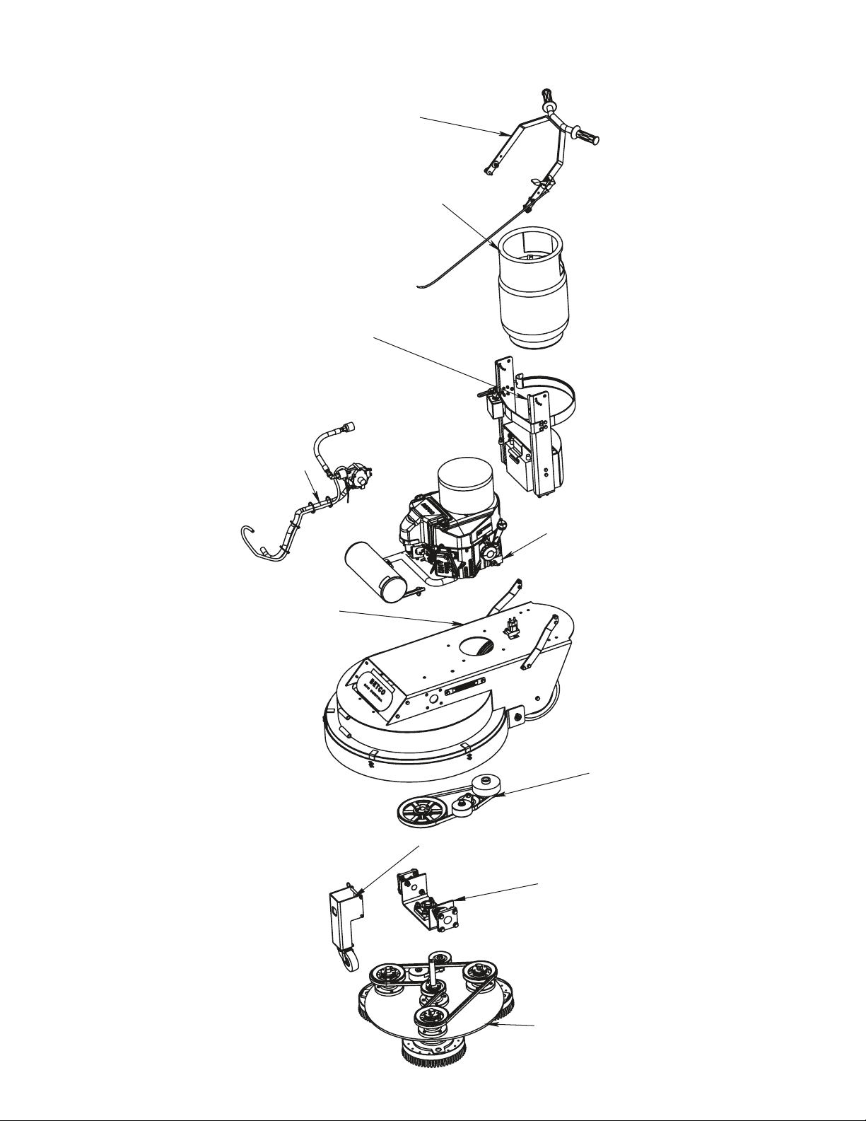
MAJOR ASSEMBLIES
HANDLE BAR ASM
OPD PROPANE TANK
LOWER HANDLE SUPPORT
REGULATOR ASM
STRIP MACHINE DECK
ENGINE ASM
BRUSH DRIVE
TRANSPORT WHEEL ASM
PIVOT BRACKET
BRUSH DECK ASM
7
Page 8
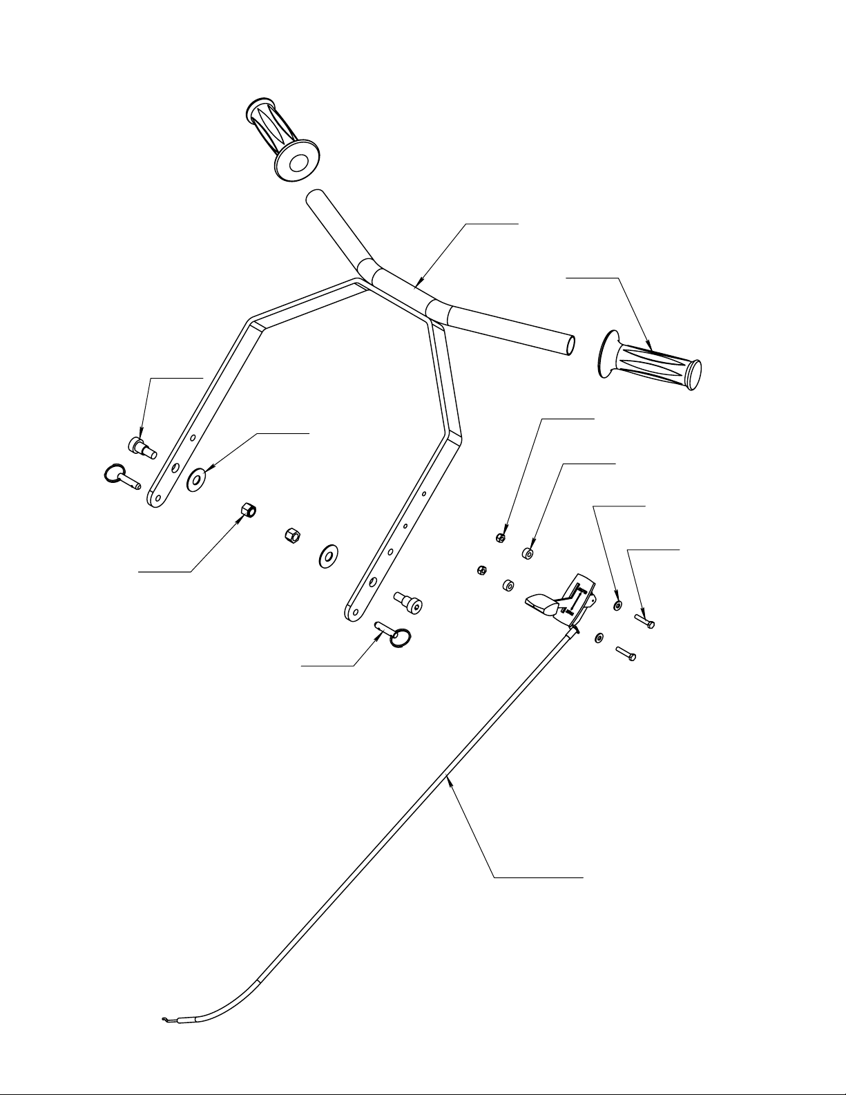
HANDLE BAR
E12476
E88808
E12696
E10120
E83145
E86228
E11146
E11420
E86125
E87986
E86114 (38")
8
Page 9

PART
NUMBER
E10120
E11146
E11420
E12476
E12696
E83145
E86114
E86125
E86228
E87986
E88808
Nut, #10-32, Nylon Lock, Grade 5, Zinc
Nut, 3/8"-16, Nylon Lock, Grade 5, Zinc
Washer, #10 SAE, Zinc
Screw, Shoulder 1/2" x 1/2" Socket Head
Hand Grip
Washer, Nylon 1/2" ID X 1.25" OD
Kawasaki Throttle Cable 38" L
Screw, #10-32 x 1.000 Hex Head, Zinc
Spacer, #10 ID x 1/2" OD x 1/4" Long, Black Nylon
Pin, 5/16" x 3/4" Detent with Ring
Handle Bar Weldment
Note: Not available for purchase assembled.
Description
QTY.
2
2
2
2
2
2
1
2
2
2
1
9
Page 10

LOWER HANDLE SUPPORT
(For Serial Numbers Before 6999)
E86125
E81072
E81089
E86125
E86119
E10457 (4")
E11702
E88806
E10120
E86120
E10457 (13")
E10761
E81063
E88316
E81072
10
E11353
E10734
E88807
E88319
E83629
E81062
E11146
E81089
E88805
E86125
Page 11
PART
NUMBER
E10120
E10457
E10734
E10761
E11146
E11353
E11702
E81062
E81063
E81072
E81089
E83629
E86119
E86120
E86125
E88316
E88319
E88805
E88806
E88807
Nut, #10-32, Nylon Lock, Grade 5, Zinc
Felt, 1.500 W x 0.125 Thick, Adhesive Back
Screw, 1/4"-20 x 0.625 Hex Head, Grade 5, Zinc
Rubber Propane Tank Shelf Pad
Nut, 3/8"-16, Nylon Lock, Grade 5, Zinc
Tube Clamp 3/4" (COV-1309)
Propane Tank Strap Latch
Washer, 5/16" USS, Zinc
Nut, 5/16"-18, Nylon Lock, Grade 5, Zinc
Screw,5/16"-18 x 1.000 Hex Head, Grade 5, Zinc
Screw, 5/16"-18 x 0.750 Hex Head, Grade 5, Zinc
Screw, 3/8"-16 x 1.250 Hex Head, Grade 5, Zinc
Hour Meter, SenDEC 5-80V
Propane Tank Strap Back
Screw, #10-32 x 1.000 Hex Head, Zinc
Battery Cover
Propane Tank Shelf
Lower Handle Leg Left
Lower Handle Leg Right
Propane Tank Strap Front
Note: Not available for purchase assembled.
Description
QTY.
4
2
1
1
4
1
1
4
10
4
6
4
1
1
8
1
1
1
1
1
11
Page 12

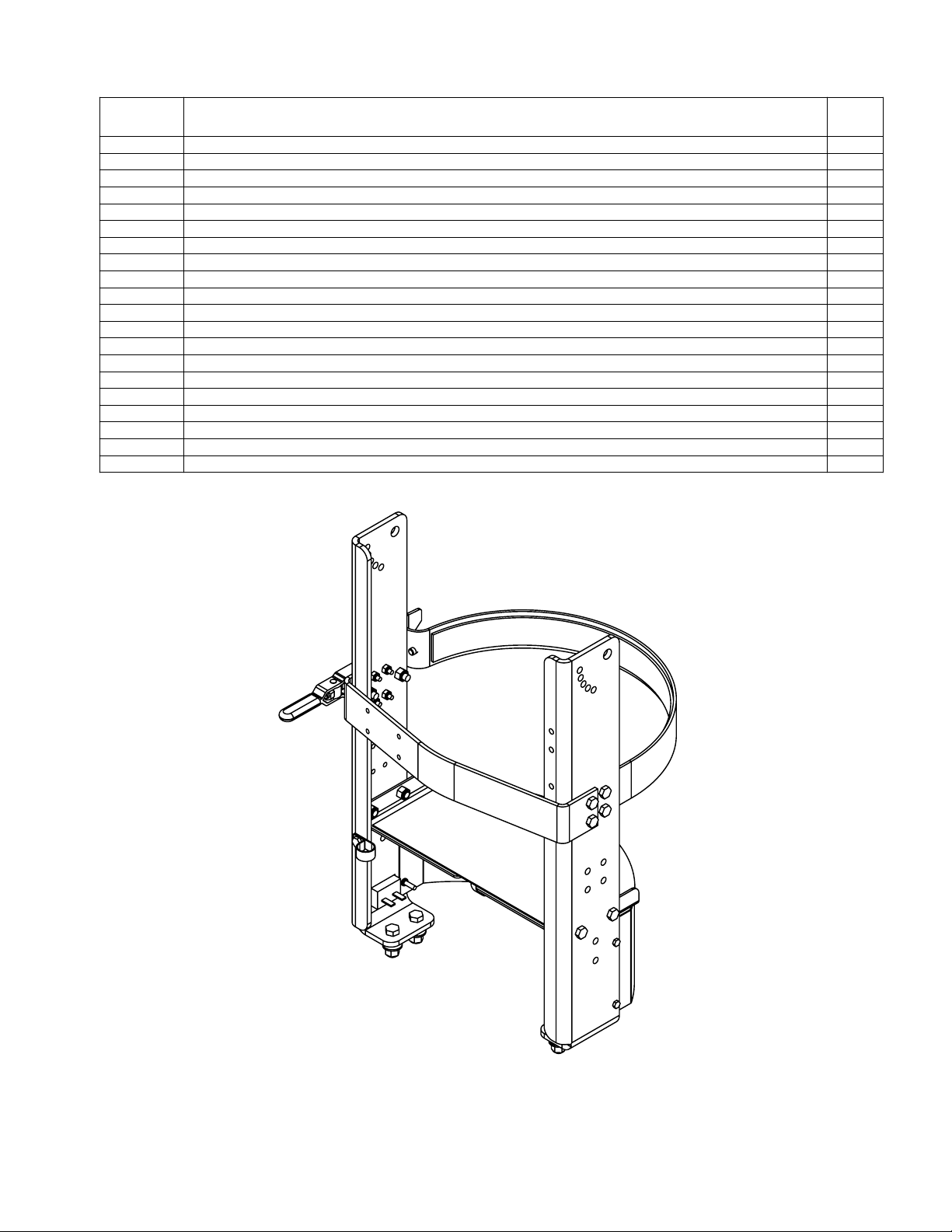
LOWER HANDLE SUPPORT
(For Serial Numbers 7000 and Greater)
E89825
E86120
E10457 (13")
E86125
E81089
E86119
E10457 (4")
E88807
E11702
E89823
E10141
E89822
E10120
E81072
E89826
12
E11353
E10734
E81062
E81062
E89824
E11146
E89827
Page 13

Note: Not available for purchase assembled.
13
Page 14

REGULATOR ASSEMBLY
E10751
E12359
E10243 (Emissions)
E10246
E88803 (36")
E10084
E88804
E11321
E11353
E88510 (24")
E10746
E10734
E88509
12V STARTER SWITCH
E12290
E86125
E10550
E10449
E86121
E10204
14
Page 15

PART
NUMBER
E10084
E10243
E10246
E10734
E10746
E10751
E11321
E11353
E12359
E88509
E88510
E88803
E88804
Fitting, 3/8 MJIC x 3/8 MNPT, 90 Elbow, Brass
In Line Fuel Shut Off Valve Model 152 (With Emissions)
In Line Fuel Shut Off Valve Model 151
Screw, 1/4"-20 x 0.625 Hex Head, Grade 5, Zinc
Fuel Regulator Model 60E
Propane Tank Coupling 7141F
Screw #10 x 5/8" Sheet Metal, Pan Head, Phillips, Black
Tube Clamp 3/4" (COV-1309)
Propane Tank Hose 1/4" MNPT - 3/8" MJIC 16.50" L
Fitting, Hose Barb 3/8" MNPT x 1/2" Barb, Brass
1/2" ID Braided Gasoline Fuel Hose (24")
Hose, 3/16" ID Vacuum
Fitting, 1/4"-28 Thread, 1/4" OD, 0.046 Wall,0.700 L, Brass
Note: Not available for purchase assembled.
Description
QTY.
1
1
1
2
1
1
1
1
1
1
1
1
1
PART
NUMBER
E10204
E10449
E10550
E12290
E86121
E86125
Wire Clamp, 3/8" Romex Connector
5 Wire Keyed Ignition Switch
Decal, OFF/ON/START
Ignition Switch Key
Key Switch Box
Screw, #10-32 x 1.000 Hex Head, Zinc
Note: Not available for purchase assembled.
Description
QTY.
1
1
1
1
1
4
15
Page 16

KAWASAKI ENGINE ASSEMBLY
Full Throttle = 3600
E10242 - Emission Kit (E10248
& E10249)
E10245 - Bung Plug M18 x 1.5mm
E10337 - Valve Oil Seal
E10544 - Decal, Clutch
E12426 - CO Detection Badge
E12525 - Drive Shaft Oil Seal
E85461 - Oil Drain Hose ASM
E88326 - Spark Plug
E88327 - Ignition Coil ASM
E88328 - Air Intake Manifold
E88468 - Head Gasket
E88469 - Cylinder 1 Head ASM
E88470 - Cylinder 2 Head ASM
E88471 - Valve Cover Gasket
E88472 - Intake Valve
E88473 - Exhaust Valve
E88476 - Dipstick Tube O-Ring
E88511 - Voltage Regulator
EP50146 - LP Ready Kawasaki
Engine ASM
With Emission Kit
(E10242)
EP50147 - LP Ready Kawasaki
Engine ASM
E88478
E88465
E88464
E88484
E10545
E88328
E12360
E88859
E88480
E88482
E88121
E11321
E10248
E88481
E88474
E88504
E88502
E88503
E88501
E88483
Engine RPM
E88325
E10895
E88477
E88479
EP50154
E10116
E10135
E10249
E11819
E12405
E10549
E88475
E10137
E88486
E88466
E81066
E81087
Idle = 1700 - 1780
16
E11418
Page 17

PART
NUMBER
E10116
E10135
E10137
E10242
E10245
E10248
E10249
E10337
E10544
E10545
E10549
E10895
E11321
E11418
E11819
E12360
E12405
E12426
E12525
E81066
E81087
E85461
E88121
E88325
E88326
E88327
E88328
E88464
E88465
E88466
E88468
E88469
E88470
E88471
E88472
E88473
E88474
E88475
E88476
E88477
E88478
E88479
E88480
E88481
E88482
E88483
E88484
E88486
E88501
E88502
E88503
E88504
E88511
E88859
EP50146
EP50147
EP50154
Description
Screw, 7/16"-14 x 1.250 Hex Head, Grade 5, Zinc
Washer, 3/8" USS, Zinc
Clamp, Tube 1/2" (COV-0909)
Emissions Kit (E10248, E10249)
Bung Plug M18 x 1.5mm
O2 Sensor Electrical Control Box
O2 Sensor
Valve Oil Seal
Decal, Clutch
Decal, Read Oners Manual
Decal, Caution Oil Pressure Switch
Gasket, Carburetor to Air-Fuel Hub
Screw #10 x 5/8" Sheet Metal, Pan Head, Phillips, Black
Nut, 7/16"-14, Nylon Lock, Grade 5, Zinc
Stud, 8mm x 18mm L
Cooling Air Intake Filter
Oil Pressure Switch
CO Detector Badge
Drive Shaft Oil Seal
Washer, 3/8" Split Lock, Zinc
Screw, 3/8"-16 x 1.500 Hex Head, Grade 5, Zinc
Oil Drain Hose Accessory
Decal, Emissions Warning Light
Air Intake Filter Paper
Spark Plug
Ignition Coil ASM
Air/Fuel Intake Manifold
O-Ring 12.5mm ID x 3.4mm T
Air Filter Thumb Nut
12V Starter
Head Gasket
Cylinder 1 Head ASM
Cylinder 2 Head ASM
Valve Cover Gasket
Intake Valve
Exhaust Valve
Oil Dipstick
Oil Filter
O-Ring
Stud, 6mm x 95mm L
Air Intake Filter Foam
Muffler Gasket
Cooling Air Intake Guard
Decal, Emissions
Decal, Air Filter Cover
Muffler, Catalytic, & Manifold Kawasaki FS481V
Air Filter Cover
Kawasaki Engine Gasoline Ready 16HP
Carburetor Intake Neck
Air Intake Elbow
Air Intake Elbow to Neck Clamp
Air Intake Elbow to Filter Clamp
Voltage Regulator
Rivet, Push, Cooling Air Intake Guard, FS481V ASM
LP Ready Kawasaki Engine Assembly With Emission Kit (E10242)
LP Ready Kawasaki Engine Assembly
Carburetor, LP Gas FS481V
QTY.
1
1
1
1
1
1
1
4
1
1
1
2
2
1
4
1
1
1
1
4
4
1
1
1
2
2
1
2
2
1
2
1
1
2
2
2
1
1
1
2
1
2
1
1
1
1
1
1
1
1
1
1
1
3
1
1
1
17
Page 18

DECK ASSEMBLY
E11772
E10734
E81089
E81067
E88320
E11164
E81089
E88315
E81089
E81067
E10120
E81063
E81063
E88314
E81067
E81089
E81089
E81067
E81089
E12693
E88323
E11165
E11501
E12476
E81066
E12483
E11339
E11170
E11420
E10120
E11420
E11335
E11340
E11351
E10120
E11163
E11420
E86125
E11416
E11135
E81066
E83629
18
Page 19

DECK PARTS
PART
NUMBER
E10120
E10734
E11135
E11163
E11164
E11165
E11170
E11335
E11339
E11340
E11351
E11416
E11420
E11501
E11772
E12476
E12483
E12693
E81063
E81066
E81067
E81089
E83629
E86125
E88314
E88315
E88320
E88323
DESCRIPTION
NYLOC HEX NUT 10-32
HEX HEAD BOLT 1/4-20 x 5/8 LG
WASHER, 3/4" SAE, ZINC
DECAL TENSIONER ACCESS
DECAL, BELT PATH
SPLASH SKIRT, 30 INCH
TENSIONER ACCESS COVER
WHEEL 10 INCH DIA x 2.50 WIDE
SPLASH SKIRT HANGER
WHEEL AXLE 3/4 OD
SHAFT COLLAR 3/4 ID
RUBBER SPLASH GUARD
FLAT WASHER #10 ZINC
WASHER, 7/16 USS, ZINC
SOLENIOD 12 VDC
SHOULDER SCREW 3/8-16 x 1/2 DIA x 1/2 LG
FLAT HEAD SCREW 10-32 x 5/8 LG
DECAL, BIG BERTHA
NYLOC HEX NUT 5/16-18 ZINC
SPLIT LOCK WASHER .375
LOCK WASHER 5/16
HEX HEAD BOLT 5/16-18 x 3/4 LG
HEX HEAD BOLT 3/8-16 x 1-1/4 LG
HEX HEAD BOLT, 10-32 x 1.00 LG
HANDLE SUPPORT LEFT
HANDLE SUPPORT RIGHT
EXTREME STRIP FRAME 30 ASSEMBLY
FRONT ACCESS PANEL
QTY.
12
2
2
1
1
1
1
2
4
1
2
1
14
2
1
2
8
1
4
4
10
14
2
3
1
1
1
1
E81088
PART
NUMBER
E81088
E86118
E87989
E87990
TRANSPORT
WHEEL ASSEMBLY
E87989
E87990
E86118
DESCRIPTION
NYLOC JAM NUT 1/2-13
3 INCH SWIVEL CASTER
TRANSPORT WHEEL
BRACKET
DETENT PIN 3/8 x 4.0, RING
QTY.
1
1
1
2
19
Page 20

MAIN DRIVE SYSTEM
E81064
E81078
E86232
E12434
E11289
E12400
E12459
E11350
E11501
E12447
E10117
E10598
E12406
E12409
E11501
E11417
20
E11345
Page 21

PART
NUMBER
E10117
E10598
E11289
E11345
E11350
E11417
E11501
E12400
E12406
E12409
E12434
E12447
E12459
E81064
E81078
E86232
Washer, 7/16" Split Lock, Zinc
Screw 7/16"-20 x 1.750 Hex Head, Grade 5, Zinc
Key 1/4" x 1/4" x 1.500"
Belt, B44 V-Belt, 44"
Pulley, BK90H - 8.75 OD
Tensioner Large For Engine
Washer, 7/16" USS, Zinc
Bushing, QT 25mm Taper Lock
Screw, 1/2"-13 x 1.750 Hex Head, Grade 5, Zinc
Washer, 1/2" Split Lock, Zinc
Clutch, Centrifugal 1750 RPM 4" Dia.
Washer, 7/16" SAE, Zinc
Key 8mm x 7mm x 30mm
Screw, 1/4"-20 x 0.750 Hex Head, Grade 5, Zinc
Washer, 1/4" Split Lock, Zinc
Spacer, Clutch Strip Kaw Top 1.000 ID x 0.470 L
Note: Not available for purchase assembled.
Description
QTY.
1
1
1
1
1
1
4
1
1
1
1
1
1
2
2
1
21
Page 22

PIVOT BRACKET ASSEMBLY
(For Serial Numbers Before 6999)
E11418
E12447
E11347
E11418
E88321
E87987
E11501
E10117
E11347
E12447
E12447
E11347
E12447
E86234
E86224
22
E11430
Page 23

PART
NUMBER
E10117
E11347
E11418
E11430
E11501
E12447
E86224
E86234
E87987
E88321
Washer, 7/16" Split Lock, Zinc
Flange Bearing AMI UCF 205 Set Screws 2.75 Bolt Spacing
Nut, 7/16"-14, Nylon Lock, Grade 5, Zinc
Screw, 7/16"-14 x 2.250 Hex Head, Grade 5, Zinc
Washer, 7/16" USS, Zinc
Washer, 7/16" SAE, Zinc
Axle, Pivot, 25mm OD x 2.0" L
Screw, 7/16"-14 x 1.500 Hex Head, Grade 5, Zinc
Screw, 7/16"-14 x 1.000 Hex Head, Grade 5, Zinc
Pivot Bracket
Note: Not available for purchase assembled.
Description
QTY.
2
4
12
4
2
24
2
8
2
1
23
Page 24

PIVOT BRACKET ASSEMBLY
(For Serial Numbers 7000 and Greater)
E11418
E12447
E89818
E89828
E11347
E11418
E10117
E12447
E11347
E89816
E89817
E12447
E86234
E11418
E10117
E12447
E89782
E12447
E86234
E12447
E89819
24
Page 25

PART
NUMBER
DESCRIPTION
QTY.
E10117
E11347
E11418
E12447
E86234
E89782
E89816
E89817
E89818
E89819
E89828
Note: Not available for purchase assembled.
SPLIT LOCK WASHER 7/16
FLANGE BEARING AMI UCF 205 SET SCREWS 2.75 BOLT SPACING
NYLOC NUT 7/16-14
FLAT WASHER, 7/16, SAE
HEX HEAD SCREW 7/16-14 x 1-1/2
PIVOT BASE ASM
FLANGE-MOUNTED STEEL BALL BEARING, 1" SHAFT DIAMETER
BRONZE THRUST BEARING 1" I.D. X 1-1/2" OD X 1/16" T
CENTER SHAFT SPACER
HEX BOLT 0.4375-14 x 2.75 LG
PIVOT BRACKET
12
2
16
32
12
2
2
2
1
4
1
25
Page 26

BRUSH PLATE ASSEMBLY
E12444
E11501
E81072
E81067
E10458
E12400
E12459
E11350
E12400
E12459
E11346
E12427
E11343
E12400
E12459
E11348
E12427
E11344
E11349
26
E11336
E11501
E12409
E12406
E10117
E10116
E83641
E11342
E11414
E12444
E81063
Page 27

PART
NUMBER
E10116
E10117
E10458
E11336
E11342
E11343
E11344
E11346
E11348
E11349
E11350
E11414
E11501
E12400
E12406
E12409
E12427
E12444
E12459
E81063
E81067
E81072
E83641
DESCRIPTION
HEX HEAD SCREW 7/16-14 x 1-1/4 LG
SPLIT LOCK WASHER 7/16
TENSIONER LARGE FOR BRUSHES
BRUSH MOUNTING PLATE
BRUSH MOUNTING PLATE LH
STRIPPER CENTER DRIVE HUB ASSEMBLY
STRIPPER BRUSH DRIVE HUB ASSEMBLY
PULLEY, BK47H - 4.45 OD
PULLEY, BK62H - 5.95 OD
BELT, BB77 DOUBLE V-BELT 77"
PULLEY, BK90H - 8.75 OD
STRIP BRUSH 11" FLARED 2" HOLE
WASHER, 7/16 USS, ZINC
BUSHING, PULLEY, D25MM QT25MM
HEX HEAD BOLT 1/2-13 x 1-3/4 Lg
WASHER, 1/2 SPLIT LOCK
WASHER 1 ID x 14 GAUGE
FLAT WASHER, 5/16" SAE
MACHINE KEY 8mm x 7 mm x 30mm
NYLOC HEX NUT 5/16-18 ZINC
LOCK WASHER 5/16
HEX HEAD SCREW 5/16-18 x 1.00 Lg
HEX HEAD BOLT, 5/16-18 x 1-1/2 Lg
QTY.
16
16
1
1
3
1
3
1
3
1
1
3
2
5
1
1
8
10
5
9
1
1
9
Note: Not available for purchase assembled.
27
Page 28

ENGINE MAINTENANCE
KAWASAKI FS481V
PERIODIC MAINTENANCE
PLEASE REFER TO ENGINE OWNERS MANUAL
FOR MORE INFORMATION
Check engine oil level and add if needed
Check and clean engine intake foam and intake paper filter
Check and clean engine cooling air intake filter
General check for loose or lost nuts, screws, oil leakage,
fuel hose connection, etc.
Clean air intake foam filter
Clean air intake paper filter
Check belt tension
Change engine oil
Change oil filter
DAILY
*
*
*
*
EVERY
25
HOURS
*
*
*
EVERY
50
HOURS
*
EVERY
100
HOURS
*
EVERY
200
HOURS
Clean dust and dirt from cylinder and cylinder head
cooling fins
Tighten nuts and screws
Clean and regap sparkplugs
Replace air intake foam filter
Replace air intake paper filter
Replace spark plugs
Check and adjust valve clearance
Clean combustion chamber
Clean and lap valve seating surface
IMPORTANT NOTES:
1) Change engine oil and oil filter after first 8 hours of operation
2) Maintenance should be done by qualified personnel only
3) Change foam and paper air intake filters and spark plugs after first 25 hours of operation
*
*
*
*
*
*
*
*
*
28
Page 29

ELECTRICAL SCHEMATIC
E10248
O2 Sensor Electrical Control Box
EP50034
LP Ready 17HP Kawasaki
Engine Assembly
With Emission Kit (E10242)
Black Wire
Green Wire
E10243
In Line Fuel Shut Off Valve Model 152
E86119
Hour Meter, SenDEC 5-80V
-
+
E10553
Black 14 Gauge Wire
Blue
Wire
Red Wire
Blue
14 Gauge
Wire
E10553
Black 14 Gauge Wire
Green
14 Gauge Wire
E10249 O2 Sensor
E12405 Oil Pressure Switch
Red
14 Gauge Wire
Black
14 Gauge Wire
E10449 Ignition Switch
Yellow
14 Gauge Wire
E88511 Voltage Regulator
E12381
Black 6 Gauge Wire
-
+
E88324 Battery, 12V,12AH, 35CCA, AGM
E12380
Red 6
Gauge
Wire
Red
14 Gauge Wire
E88466
12V Starter
E12380
Red 6
Gauge
Wire
E11772 Solenoid, 12V
29
Page 30

MAIN DRIVE BELT
Removal
Remove main drive belt tensioner access plate.
1.
Remove front access panel bolts and panel.
2.
Loosen main drive belt tensioner bolt using a 3/4" wrench.
3.
Through the front access slip the belt up over the main drive pulley of the brush drive plate.
4.
You can finish removing the main drive belt through the rear opening of the machine under the handle.
5.
Installation
Insert the new main drive belt through the rear opening of the machine under the handle.
1.
Place the main drive belt around the clutch while ensuring the main drive belt tensioner pulley is in the
2.
correct location.
Put the opposite end of the main drive belt on top of the main drive belt pulley of the brush drive plate.
3.
Through the front access finish inserting the main drive belt into the main drive belt pulley groove.
4.
Tensioning
Insert a 1" wrench into the tensioner access slot onto the main drive belt tensioner hex on the main
1.
drive belt tensioner body.
Pull the wrench toward the front of the machine to tension the main drive belt.
2.
While holding the 1" wrench in place tighten the main drive belt tensioner bolt with a 3/4" wrench.
3.
Reposition the 1" wrench to add more tension to the main drive belt.
4.
While holding the 1" wrench in place then loosen the main drive belt tensioner bolt with the 3/4" wrench.
5.
Repeat steps 2 and 3.
6.
Repeat steps 5 and 6 until the main drive belt is tensioned properly. (2 or 3 repetitions)
7.
Main Drive Belt
Tensioner
Access Plate
Main Drive Belt
Tensioner Bolt
Main Drive
Belt
Main Drive
Belt Pulley
Clutch
Main Drive Belt
Tensioner Pulley
Main Drive Belt
Tensioner Bolt
Main Drive Belt
Tensioner Body
30
Page 31

BRUSH PLATE & BELT
Brush Drive Plate Removal
Remove front access panel bolts and panel.
1.
Loosen main drive belt tensioner bolt using a 3/4" wrench.
2.
Through the front access slip the main drive belt up over the main drive pulley of the brush drive plate.
3.
Remove pivot bracket axle bolts.
4.
Slide pivot bracket axles out from both sides.
5.
Tilt machine back at handle and pull backward until it clears the brush drive unit.
6.
Brush Drive Belt Removal
Loosen brush drive belt tensioner pulley bolt, located on brush side of plate, using a 3/4" wrench.
1.
Slide the belt off one of the three brush pulleys.
2.
Finish removing the belt from the rest of the pulleys.
3.
Brush Drive Belt Installation
Place the new belt around the center pulley as shown below.
1.
Now route the belt around each of the brush drive pulleys as shown below.
2.
Brush Drive Belt Tensioning
Place a 1" wrench on the tensioner hex on the top of the brush drive belt tensioner body.
1.
Pull the wrench toward the brush drive belt tensioner pulley to tension the belt.
2.
While holding the 1" wrench in place tighten the brush drive belt tensioner bolt, on the brush side of the
3.
plate, using a 3/4" wrench.
Front Access
Panel Bolts
Front Access
Panel
Engine Tensioner
Pulley Bolt
Pivot Bracket
Axle Bolts
Main Drive
Belt Pulley
Brush Drive Belt Path
Main Drive
Belt
Main Drive Belt
Tensioner Bolt
Brush Drive
Belt Tensioner
31
Page 32

BRUSH CHANGE
Remove propane tank.
1.
Remove front access panel to gain access to the brush drive shaft tops.
2.
Lay the machine on its side with the brush drive plate installed.
3.
The brush drive shaft and brush mount plate are LEFT HAND THREADS.
4.
Using a 3/4" open end wrench place it on the wrench flats of the brush drive shaft top.
5.
Place an 1 1/4" socket in the center of the brush mount plate on the bristle side.
6.
Unscrew the brush mount plate from the brush drive shaft while securing the brush drive shaft with the 3/4"
7.
wrench.
Now you'll need to remove the brush from the brush mount plate.
8.
Using a 1/2" wrench and 1/2" socket unscrew the nuts which hold the brush onto the brush mount plate.
9.
Note: When reassembling brush and brush mounting plate place bolts in through the brush mount plate
down through brush and put nuts on the bristle side of the brush.
Brush Drive
Shaft Top
Brush Mount
Plate Bottom
Brush Mount
Plate Top
See Note
Front Access
Panel
32
Page 33

TROUBLESHOOTING
PROBLEM CAUSE POSSIBLE SOLUTION
Battery is dead Recharge battery or replace if necessary
Loose wire or bad connection Check wires and connections
Engine will not turn over
Engine turns over, but will
not start
Hard to start
Engine stops suddenly
and will not restart
Engine overheats
Can't remove brushes
Poor stripping
performance or leaves
wax on the floor
Bad electrical component Replace bad component
Fuel system problem
Propane tank shut off valve in off
position
Low oil Add oil
Fuel system problem
Propane tank empty Fill propane tank
Engine problem
Throttle lever in slow position Push throttle lever to fast position
Propane tank shut off valve not
fully open
Some type of engine problem
Out of propane Replace propane tank with full propane tank
Low oil Add oil
Intake air filter is dirty Remove air intake filter and clean
Incorrect oil level Add or remove oil to achieve proper oil level
Turning brushes the wrong
direction
Brushes worn and have 3/4"
bristle length or less
Brush or main drive belt slipping Tension belts or replace belts if worn out
Problem with stripper Check dilution ratio or try alternative stripper
Refer to engine owner’s manual and read
IMPORTANT below
Open propane tank shut off valve completely
Refer to engine owner’s manual and read
IMPORTANT below
Refer to engine owner’s manual and read
IMPORTANT below
Open propane tank shut off valve completely
Refer to engine owner’s manual and read
IMPORTANT below
Turn clockwise to remove. Threads are LEFT HAND
Change the brushes
Excessive splashing Splash guard too high off floor Adjust splash guard down
Solution pushed by
splash guard
Brushes not turning,
turning slow or smell
burning rubber
Lacks power Some type of engine problem
Engine stops and will
restart, but stops again
Nothing here fixes the
problem
Splash guard too low Adjust splash guard up
Brush or main drive belt slipping Tension belts or replace belts if worn out
Floor too rough to overcome
friction, may happen on rough
concrete surface
Emission shut-down system
engaged
Problem could have several
causes
Check belts for proper tensioning or for excessive
wear and ensure there is plenty of liquid on the floor.
Refer to engine owner’s manual and read
IMPORTANT below
Refer to engine owner’s manual and read
IMPORTANT below
Read IMPORTANT below
IMPORTANT: Propane fueled combustion engines produce dangerous gases and must be serviced by authorized
service personnel trained specifically to service propane fueled engines and fuel systems. The troubleshooting
tips are not intended to take the place of authorized service personnel. If you are unsure of what to do contact an
authorized service personnel. Before working on this machine you must be familiar with the safety instructions in
this manual.
33
Page 34

EMISSION CONTROL WARRANTY STATEMENT
YOUR WARRANTY RIGHTS AND OBLIGATIONS
The California Air Resources Board and Betco Corporation are pleased to explain the emissions control system warranty on
your small off-road engine (SORE). In California and the other 49 States, new SORE must be designed, built and equipped
to meet stringent anti-smog standards. Betco Corporation must warrant the emission control system on your SORE for the
period of time listed below provided there has been no abuse, neglect or improper maintenance of your SORE.
Your emission control system may include parts such as the carburetor, fuel-injection system, the ignition system, catalytic
converter, fuel tanks, fuel lines, fuel caps, valves, canisters, filters, vapor hoses, clamps, connectors, and other associated
emission-related components.
Where a warrantable condition exists, Betco Corporation will repair your SORE at no cost to you including diagnosis, parts
and labor.
MANUFACTURER'S WARRANTY COVERAGE
The emission control system is warranted for two years. If any emission-related part on your equipment is defective, the part
will be repaired or replaced by Betco Corporation.
OWNER'S WARRANTY RESPONSIBILITIES
As the small off-road engine (SORE) owner, you are responsible for the performance of the required maintenance listed in
your owner's manual. Betco Corporation recommends that you retain all receipts covering maintenance of your SORE engine,
but Betco Corporation cannot deny warranty solely for the lack of receipts or for your failure to ensure the performance of all
scheduled maintenance.
As the SORE owner you should however be aware that Betco Corporation may deny your warranty if your SORE or its part has
failed due to abuse, neglect, improper maintenance or unapproved modification.
You are responsible for presenting your utility equipment engine to a Betco Corporation distribution center as soon as the
problem exists. The warranty repairs should be completed within a reasonable amount of time, not to exceed 30 days. If you
have any questions regarding your warranty rights and responsibilities, you should contact Betco Corporation at 1-888-GOBETCO (1-888-462-3826).
Betco Corporation
1001 Brown Ave.
P.O. Box 3127
Toledo, Ohio 43607
USA
GENERAL EMISSIONS WARRANTY COVERAGE
Betco Corporation warrants to the ultimate purchaser and each subsequent purchaser that the equipment is designed, built
and equipped so as to conform with all applicable regulations; and free from defects in materials and workmanship that cause
the failure of a warranted part to be identical in all material respects to that part as described in Betco Corporation’s application for certification.
The warranty period begins on the date the equipment is delivered to an ultimate purchaser or first placed into service. The
warranty period is two years.
Subject to certain conditions and exclusions as stated below, the warranty on emission-related parts is as follows:
1. Any warranted part that is not scheduled for replacement as required maintenance in the written instructions supplied, is
warranted for the warranty period stated above. If the part fails during the period of warranty coverage, the part will be
repaired or replaced by Betco Corporation according to subsection (4) below. Any such part repaired or replaced under
warranty will be warranted for the remainder of the period.
2. Any warranted part that is scheduled only for regular inspection in the written instructions supplied is warranted for the
warranty period stated above. Any such part repaired or replaced under warranty will be warranted for the remaining warranty period.
34
Page 35

EMISSION CONTROL WARRANTY STATEMENT
3. Any warranted part that is scheduled for replacement as required maintenance in the written instructions supplied is warranted for the period of time before the first scheduled replacement date for that part. If the part fails before the first scheduled
replacement, the part will be repaired or replaced by Betco Corporation according to subsection (4) below. Any such part
repaired or replaced under warranty will be warranted for the remainder of the period prior to the first scheduled replacement
point for the part.
4. Repair or replacement of any warranted part under the warranty provisions herein must be performed at a warranty station at
no charge to the owner.
5. Notwithstanding the provisions herein, warranty services or repairs will be provided at all of our distribution centers that are
franchised to service the subject engines or equipment.
6. The SORE owner will not be charged for diagnostic labor that is directly associated with diagnosis of a defective, emissionrelated warranted part, provided that such diagnostic work is performed at a warranty station.
7. Betco Corporation is liable for damages to other engine or equipment components proximately caused by a failure under
warranty of any warranted part.
8. Throughout the SORE warranty period stated above, Betco Corporation will maintain a supply of warranted parts sufficient to
meet the expected demand for such parts.
9. Any replacement part may be used in the performance of any warranty maintenance or repairs and must be provided without
charge to the owner. Such use will not reduce the warranty obligations of Betco Corporation.
10. Add-on or modified parts that are not exempted by the Air Resources Board may not be used. The use of any non-exempted
add-on or modified parts by the ultimate purchaser will be grounds for disallowing a warranty claims. Betco Corporation will
not be liable to warrant failures of warranted parts caused by the use of a non-exempted add-on or modified part.
WARRANTED PARTS
The repair or replacement of any warranted part otherwise eligible for warranty coverage may be excluded from such warranty
coverage if Betco Corporation demonstrates that the SORE has been abused, neglected, or improperly maintained, and that such
abuse, neglect, or improper maintenance was the direct cause of the need for repair or replacement of the part. That notwithstanding, any adjustment of a component that has a factory installed, and properly operating, adjustment limiting device is still
eligible for warranty coverage. The following emission warranty parts are covered:
1. Fuel system: carburetor, pressure regulator, and fuel lock off
2. Ignition system: spark plug, ignition coil assembly, and voltage regulator
3. Intake system: intake manifold and air filter
4. Exhaust system: exhaust manifold and catalytic converter
5. Miscellaneous items used in above systems: hoses, connectors, and assemblies.
35
Page 36

BETCO US WARRANTY POLICY
10 year coverage
Subject to the conditions stated below,
Betco warrants parts and labor on
rotationally molded polyethylene tanks/
housings and injection molded vacuum
head assemblies to be free from defects
in materials and workmanship for
a period of ten years to the original
purchaser.
Allowable Travel Time Warranty Reimbursement:
Eligible equipment: All battery and propane powered equipment products. Warranty period: 90 days from date of sale to the
original purchaser. A maximum 180 mile round trip at 50 cents per mile will be allowed for warranty consideration.
3 Year Coverage
Subject to the conditions stated below,
Betco warrants parts and labor on all
other Betco components to be free from
defects in materials and workmanship
for a period of three years to the original purchaser.
1 Year Coverage
Subject to the conditions stated below,
Betco offers a limited warranty on parts
and labor on the following equipment:
parts and accessories to be free from
defects in materials and workmanship
for a period of one year to the original
purchaser.
• HF14 Upright Vacuum: #E88820-00
• Bac Pac Lite Vacuum: #85903-00
• FiberPRO® Floor Dryer: #85507-00
• WORKMAN™ Series Vacuums:
#85024-00, #85025-00, #83012-00,
#85027-00
• CV100T Vacuum: #85023-00
• All Tools and Accessories
• All Battery Chargers
• All Batteries are pro-rated for 1 year
Propane Machine Warranty:
Kawasaki engines are warranted by Kawasaki for a period of 2 years against manufacturer defects. All other components
(except wear items)* are warranted by Betco for a period of 3 years.
*Wear Items exempt from Warranty consideration include but may not be limited to: power cords, transport wheels,
vacuum bags, belts, squeegee blades, pad drivers, clutch plates, handle grips, filters, screens, throttle cables, brushes
and carbon brushes.
Subject to the conditions and exceptions stated in this warranty, Betco warrants the Betco products to be free from defects in
material and workmanship, under normal use and service, for the periods listed under the warranty policy to the original purchaser. At any time during the warranty period, Betco will furnish replacement parts for the Betco parts to the original purchaser. Such parts will be furnished and charged including transportation costs, to the original owner through any Betco authorized
Service Distributor. If the original part is returned within the warranty policy period from date of delivery for inspection by
Betco and is found to be defective the owner will be credited for the cost of replacement parts plus shipping and handling.
Replacement parts that have become defective through wear or abuse are not included in this warranty.
This warranty does not apply to damage or defect caused by accident, misuse. Negligence, fire, or to any Betco product which
has been serviced or repaired by other than an authorized Betco Service Distributor or Betco factory personnel. This warranty
is void if products are used for any purpose other than that which was intended. There are no other warranties expressed or
implied. In no event shall Betco be liable for incidental or consequential damages or any damage to person or property. (Please
note some states do not allow the exclusion or limitations for incidental and consequential damages).
36
Customer Service: 888-GO-BETCO • Fax: 800-445-5056 • Technical Service: 877-856-5954 • www.betco.com
1001 Brown Avenue • Toledo, Ohio 43607-0127
E12327-94 Sept13R
 Loading...