


LaserSpeed LS9000
OPERATOR GUIDE
- for daily operation -
Manual Part Number: 93296 • Manual Drawing Number: 0921-01419 • English • Revision F • © Copyright Feb 2013
www.betalasermike.com

Declaration of Conformity
LaserSpeed 9000 Operator Guide
Declaration of Conformity
Part No. 93296 / Drawing No. 0921-01419 Page 2 of 16 Revision F (Feb 2013)

LaserSpeed 9000 Operator Guide
Contents
Declaration of Conformity ....................................................................... 2
Contents ................................................................................................... 3
Proprietary Statement .............................................................................. 4
European Commission Requirements .................................................... 5
Safety Information .................................................................................... 6
Intended Use ........................................................................................................ 6
Laser Classification .............................................................................................. 7
Laser Safety Precautions ..................................................................................... 8
Labels and Safety Features ................................................................................. 9
Introduction .............................................................................................11
Quick Start ...............................................................................................11
LaserTrak Software .................................................................................12
LaserTrak for Windows ...................................................................................... 12
Gauge Alignment ................................................................................................ 12
Contents
Servicing and Returning Your Equipment .............................................16
Part No. 93296 / Drawing No. 0921-01419 Page 3 of 16 Revision F (Feb 2013)

LaserSpeed 9000 Operator Guide
Note:
For
information
about
servicing and
returning your
equipment,
see the
section at the
end of this
manual.
Proprietary Statement
Manufacturer/Distributor
Beta LaserMike, 8001 Technology Blvd., Dayton, OH 45424, USA
About This Manual
This manual contains descriptions, drawings, and specifications for a Beta LaserMike product. Equipment or
products made prior to or subsequent to the publication date of this manual may have parts, features, options, or
configurations that are not covered by this manual. Specifications contained herein are subject to change by Beta
LaserMike without prior notice. Beta LaserMike is not responsible for errors or omissions that may be contained
herein or for incidental or consequential damages in connection with the furnishing or use of this information.
Comments or suggestions for possible improvements to the manual are appreciated. Please email us at
manualfeedback@betalasermike.com.
The information contained in this manual is the property of Beta LaserMike. The information disclosed in this
document is furnished in confidence and upon the condition that individual and corporate intellectual rights, whether
patented or not, will be respected. If this document is supplied on removable media (e.g. CD), an electronic copy
(stored on-site) and one printout is permitted. If this document is supplied in printed form, no part of this document
may be reproduced or scanned without the prior written consent of Beta LaserMike. This document may not be
distributed or circulated to third parties.
Proprietary Statement
Limited Warranty
Beta LaserMike will correct by repair, or at Beta LaserMike‘s option, by replacement, F.O.B Beta LaserMike’s plant,
any defect in workmanship or material in any equipment manufactured by Beta LaserMike which appears under
normal and proper use within twelve months from the date of shipment (eighteen months for OEM’s), provided Beta
LaserMike is given reasonable opportunity to inspect the alleged defective equipment at the place of its use and
under conditions of its use.
EXCLUSIONS: This warranty does not cover products which have been modified, altered, or repaired by any other
party than Beta LaserMike or its authorized agents. Furthermore, any product which has been, or is suspected of
being damaged as a result of negligence, misuse, incorrect handling, servicing, or maintenance; or has been
damaged as a result of excessive current/voltage or temperature; or has had its serial number(s), any other
markings, or parts thereof altered, defaced, or removed will also be excluded from this warranty.
WARRANTY SERVICE AT CUSTOMER SITE: Warranty service performed at the customer’s facility will be free of
charge for parts and labor; however, the customer will be liable for transportation and living expenses of personnel
dispatched to effect such repair. A purchase order or other written confirmation of the acceptance of these charges,
signed by an authorized individual, will be required prior to commencement of repairs. Additional charges may be
assessed the customer if: 1) The equipment is not made available on a timely basis, 2) The equipment is found to
be without fault, and/or 3) It is determined the equipment is not under warranty, whether by expiration of the
warranty or any act which voids the warranty.
OTHER THAN AS SET FORTH HEREIN, BETA LASERMIKE MAKES NO WARRANTIES, EXPRESSED OR
IMPLIED, OF MERCHANTABILITY AS TO THE EQUIPMENT MANUFACTURED BY IT, AND THERE ARE NO
EXPRESSED OR IMPLIED WARRANTIES WHICH EXTEND BEYOND THE DESCRIPTION ON THE FACE
THEREOF. Beta LaserMike’s obligation to correct defects in such equipment by repair or replacement in
accordance with the foregoing provisions is in lieu of any other warranties, expressed or implied, and in no event
shall Beta LaserMike be liable for incidental or consequential damages. No service of Beta LaserMike’s equipment
is permitted during the warranty period without the specific written consent of Beta LaserMike.
Part No. 93296 / Drawing No. 0921-01419 Page 4 of 16 Revision F (Feb 2013)

LaserSpeed 9000 Operator Guide
European Commission Requirements
European Commission Requirements
This equipment is intended for use in a heavy industrial environment. The equipment generates, uses and
can radiate radio frequency energy and, if not installed and used in accordance with the instructions, may
cause harmful interference to other equipment. There is no guarantee that interference will not occur in a
particular installation. If this equipment does cause harmful interference to other equipment the user is
encouraged to try to correct the interference by one or more of the following measures:
- Re-orientate or relocate the equipment.
- Increase the separation between the pieces of equipment.
- Connect the pieces of equipment on separate mains circuits.
- Ensure that the relevant items of equipment are properly and securely earthed to a common earth point
using adequately sized cable or other means of connection.
Where supplied or specified, shielded interconnection cables must be employed with this equipment to
ensure compliance with the pertinent RF limits. Changes or modifications not expressly approved by the
company could void the user’s authority to operate the equipment.
This product has been rigorously tested to comply with the European EMC (Electromagnetic Compatibility)
Directive. With regard to this, Beta LaserMike recommends that any non-Beta LaserMike peripheral
equipment is CE marked for the Heavy Industrial environment (EN50082-2). Beta LaserMike also
recommends that any cables not supplied by Beta LaserMike, but used for powering Beta LaserMike
equipment, be built using good EMC practices (i.e. cables with braided shield, and connectors with 360
termination of the braid to a metal/metalised shell connector at both ends). If you have any questions
regarding this, contact the Beta LaserMike Service Department.
Part No. 93296 / Drawing No. 0921-01419 Page 5 of 16 Revision F (Feb 2013)

LaserSpeed 9000 Operator Guide
Safety Information
Under NO circumstances should the earth safety connections
be broken – internal damage to sensitive electronic components
may occur and at worst electrocution to personnel may result.
This equipment must be earthed/grounded.
Relays and associated wiring are rated for SELV levels i.e. 60
VDC & 30 VAC RMS. These levels must not be exceeded.
Maintenance, repairs and electrical connections should be
performed by a suitably qualified person for the country of
installation.
Input power to the equipment is of direct current type
designated by the symbol on equipment housing and shown
below.
Safety Information
Reference: IEC 60417-5031
The equipment contains a slow blow type fuse to protect against
input power overloads and is not user replaceable.
Intended Use
If the equipment is used in a manner not specified by the manufacturer, the
protection provided by the equipment may be impaired.
Part No. 93296 / Drawing No. 0921-01419 Page 6 of 16 Revision F (Feb 2013)

Laser Classification
The Model LS9000 Non-contact Length and Speed
Gauge (Model LS9000) is classified as a IIIb laser device.
This category contains infrared and visible laser devices
with powers up to 500 mW. The optical gauge in the
system uses a 50 mW solid-state laser device operating
between 760 and 800 nm (near infrared region of the
spectrum).
A class IIIb product must have the following safety
features:
A 5-second delay after power-up before laser
radiation is emitted from the gauge.
An indicator light to inform personnel near the
gauge that laser radiation is being emitted.
LaserSpeed 9000 Operator Guide
Safety Information
A mechanical device to physically block the laser
beam from exiting the gauge.
An interlock circuit to shut off the laser when the
circuit is opened.
All hazards must be properly identified with warning labels.
These basic safety features are incorporated to promote safe operation of the
laser.
A class IIIb laser must also have a key switch to power the laser, ensuring that
only trained personnel can operate the instrument. Because the location of the
gauge can often make it difficult to access a key switch, the key switch needs
to be installed by the final user. It should be placed in a location that will be
readily accessible to the operators. For more information on installing the laser
key switch, see the Installing the System section of the Instruction Handbook.
The user of a laser device must comply with a different set of regulations.
Many countries and individual states have passed legislation regarding the use
of laser products.
Part No. 93296 / Drawing No. 0921-01419 Page 7 of 16 Revision F (Feb 2013)
LaserSpeed 9000 Operator Guide
Maximum Laser Power
0.050 watt
Laser Wavelength
0.785 micrometer
Minimum Laser Spot Size
(Elliptical)
5 x 3 millimeters
Beam Divergence
0.5 milliradians
Pulse Rate
Continuous wave
Maximum radiance (power
divided by spot-size area)
0.050 Watt / 0.1 cm2
[0.5 W/cm2]
The following system specifications will help establish appropriate safety
measures.
Laser Safety Precautions
The laser beam in the optical gauge is very powerful and can permanently
damage eyes not protected by laser safety glasses. To avoid exposing
yourself to hazardous radiation, you must take these precautions:
Safety Information
Never look into the laser beam. If you must look at the beam,
view it from an angle and in the direction in which the beam is
travelling.
The beams emitted from the Model LS9000 are invisible to the
unaided eye. Return the beam shutter to the closed position
when the system is not in use or during setup.
Ensure that all direct reflections are blocked.
Remove all rings, watches, or jewellery from your hands when
working on or near the gauge—can cause hazardous reflections.
Never install the instrument at eye level.
Operate the system only with people who have been instructed
in laser safety.
Post warning signs and lights that are active when laser is
operating.
If your country or state has no regulations governing the safe use of lasers,
Beta LaserMike recommends that you follow the guidelines specified by the
American National Standard for the safe use of lasers (ANSI Z136.1–1986).
For a copy of this document, write to:
Laser Institute of America
13501 Ingenuity Drive, Suite 128
Orlando, Florida 32826
1-800-345-2737
Part No. 93296 / Drawing No. 0921-01419 Page 8 of 16 Revision F (Feb 2013)

LaserSpeed 9000 Operator Guide
IDENTIFICATION
LABEL
LASER
WARNING
LABEL
Labels and Safety Features
This section acquaints you with the advisory and identification labels on the
instrument and the safety features incorporated into the design of the
instrument. The following figures show the advisory and identification labels
on the Model LS9000.
LS9000 Labels
Safety Information
Part No. 93296 / Drawing No. 0921-01419 Page 9 of 16 Revision F (Feb 2013)
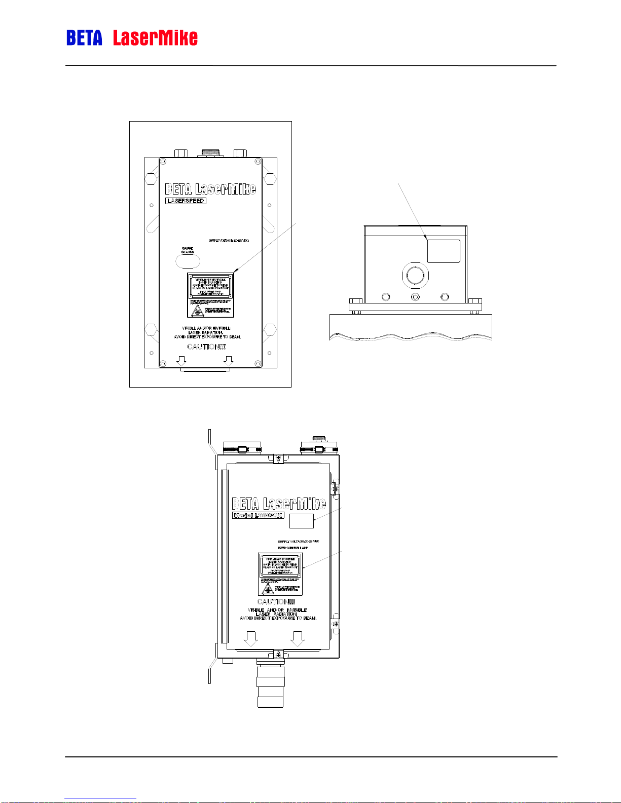
IDENTIFICATION
LABEL
LASER
WARNING
LABEL
IDENTIFICATION
LABEL
LASER
WARNING
LABEL
LS9000E Labels
LaserSpeed 9000 Operator Guide
Safety Information
LS9000X Labels
Part No. 93296 / Drawing No. 0921-01419 Page 10 of 16 Revision F (Feb 2013)

LaserSpeed 9000 Operator Guide
Power Connection
The sensor requires 24 VDC of power at 1.5 amps. Connect +24 VDC
to input pins 24 and 25 (+24V Power Input) on the 25-pin D-sub
connector on the back of the LS9000 sensor. Connect the power
ground to pins 12 and 13 (Power Ground for 24V Input) on the 25-pin
D-sub connector on the LS9000 sensor.
Shutter Control
Connect pin 17 (Shutter Control) to pin 11 (Signal Ground). This will
open the shutter and permit the laser beams to exit the sensor.
Laser Interlock
Connect pin 16 (Laser Interlock) to pin 21 (Signal Ground). This will
power the laser. With +24 VDC connected and pin 16 (Laser Interlock)
and pin 17 (Shutter Control) grounded, the laser will be visible on
paper held in front of the LS9000 sensor.
RS232 Interface
For 9-Pin D-sub Computer
Serial Port
Connect the RS232 Cable from the 9 pin “D” connector on the
Breakout terminal strip to the Comm port on your computer. The cable
is a straight through cable without any pin reversal. The male end
connects to the 9 pin connector on the terminal strip for the gauge and
the female end connects to the computer.
Introduction
This manual describes the daily routine usage of the LaserSpeed 9000 Gauge.
For installation and setup, see the LaserSpeed 9000 Instruction Handbook.
The Model LS9000 LaserSpeed® Non-Contact Length and Speed Gauge is an
industrial, laser-based instrument that measures the velocity and length of
moving material. Due to the nature of the laser-based measurement, there is
no physical contact with the material.
Quick Start
The following will help you set up and operate the LS9000 for the first time.
You can also use this information to check for possible connection problems
during troubleshooting.
Introduction
Run the LaserTrak system software. Check for proper RS232 connection at a
baud rate of 115,200. If the interface fails, perform a search with the LS9000
software to make the connection. If the search fails, re-check all RS232
connections and search again. If the RS232 still is not working, try another
computer. Some computers do not support a baud rate of 115,200.
Part No. 93296 / Drawing No. 0921-01419 Page 11 of 16 Revision F (Feb 2013)

LaserSpeed 9000 Operator Guide
LaserTrak Software
LaserTrak® is a Windows®-based software program, which allows you to
acquire and display the Length, Velocity, Quality Factor, and Gauge Status in
real time. The LaserTrak software configures the gauge’s operating
parameters, displays data, and collects data, which can be stored on a
computer hard drive. This LaserSpeed series of non contact speed and length
gauges provide a set of versatile tools that are applicable for a wide variety of
process measurement schemes. LaserTrak allows you to take full advantage
of this versatility in a straightforward, easy to understand manner.
There are several features available with the LaserTrak software. LaserTrak
mimics a chart recorder output on the screen and monitor the speed, length
and Quality Factor in real time and presents a time history depiction of the
data. LaserTrak can acquire and store data, and load and display stored data
from a previously acquired data file.
LaserTrak Software
LaserTrak also allows the configuration of the gauge operating parameters to
optimize the gauge’s performance for each application. The gauge can
emulate any mechanical pulse tachometer by using the gauge configuration
feature. To configure the pulse outputs or any other parameter of the gauge,
Click on “tools”, then click on “LaserSpeed Configuration”. Change the
operating parameters to match your operating conditions and then save the
parameters to the gauge by clicking on close. Once the parameters have been
saved to the gauge you do not need the LaserTrak software to operate the
gauge. However, LaserTrak software can be a very useful tool in getting
familiar with the gauge’s operation and performance. It can be useful to
monitor the gauge's operation until you are comfortable with the gauge’s
performance.
LaserTrak for Windows
Note: LaserTrak Version 4.0 or later must be used with the LS9000 gauge.
1) Make sure the RS232 cable is properly connected to the gauge and the
computer. See the LS4000-3 Instruction Handbook if more information
is needed.
2) Make sure the power is applied to the gauge.
Part No. 93296 / Drawing No. 0921-01419 Page 12 of 16 Revision F (Feb 2013)
®
Windows 98, NT 2000 and Windows XP are registered trademarks of Microsoft
Corporation.

LaserSpeed 9000 Operator Guide
LaserTrak Software
3) Check status lights on the gauge. The power light should be on and the
Laser on light should be on. This indicates that power has been applied
to the gauge and the Interlock is closed so the Laser power can be
applied.
4) Click on the LaserTrak Icon to start the LaserTrak Software.
a) The LaserTrak software should search all COM ports on the
computer and find the COM port that the gauge is connect to.
Check the LS4000-3 Instruction Handbook for more information
if the software does not find the gauge.
b) Once communication has been established between the
LaserTrak software and the gauge, the software will display the
Chart Recorder screen.
c) Click on “Tools” then “LaserSpeed Configuration” to go the
configuration screen.
d) Change the configuration settings to correspond to your
application.
e) Click Close and update the setting to the gauge.
f) The gauge is now ready to start measuring.
Part No. 93296 / Drawing No. 0921-01419 Page 13 of 16 Revision F (Feb 2013)

LaserSpeed 9000 Operator Guide
Gauge Alignment
LaserSpeed gauges have a standoff distance and a depth of field the product
needs to stay within in order to make measurements. The last two digits of the
model number indicate the standoff distance. For example model LS9000-303,
the last two digits are 03 meaning 300 mm (11.8 inches). See the LS9000
Instruction Handbook for more details. The 300 mm (11.8 inch) standoff
means the product has to be 300 mm or 11.8 inches from the product. Model
LS9000-303 also has a 37 mm or 1.45 inch depth of field. This means the
product has to be 300 mm (11.8 inches) from the gauge ± 17.5 mm (±0.69
inches).
LaserTrak Software
The laser beam needs to get aligned to the center 20% on round product. For
flat products, the product just needs to be within the depth of field of the
gauge. Normally, the gauge will be aligned perpendicular to the product. See
the LS9000 Instruction Handbook for alignment error if not mounted
perpendicular to the product.
The gauge should be making accurate speed and length measurements once
the gauge has been mounted and aligned properly. The Speed and Length
measurements along with Quality Factor can be monitored using a computer
and the LaserTrak software.
Part No. 93296 / Drawing No. 0921-01419 Page 14 of 16 Revision F (Feb 2013)

LaserSpeed 9000 Operator Guide
Speed Graph
Quality Factor Graph
The Chart Recorder Screen acquires Speed, Length, Quality Factor and
Status from the gauge and displays them on a chart recorder screen.
Chart Recorder Screen
LaserTrak Software
The Quality Factor represents how well the gauge is measuring the product.
Quality Factor ranges from 0 to 15, with 15 being the best. Always try to get
Quality Factor to equal 15. If Quality Factor is not 15, check the standoff
distance, the alignment, make sure the product does not have any water on
the surface. See the LS9000 Instruction Handbook for more details.
Part No. 93296 / Drawing No. 0921-01419 Page 15 of 16 Revision F (Feb 2013)

LaserSpeed 9000 Operator Guide
Servicing and Returning Your Equipment
Servicing and Returning Your Equipment
Your instrument was carefully inspected electrically and mechanically prior to
shipment. It should be free of surface mars and scratches, and it should be in
perfect working order upon receipt. If any indication of damage is found, file a
claim with the carrier immediately, prior to using the instrument. If no damage
is apparent, proceed by using this manual to install and setup this instrument.
Save the shipping carton and packing material for future storing or shipment of
the instrument. If, at some future time, the instrument must be returned to the
factory for service, include a full description of the instrument failure and the
mode of operation the instrument was in at the time of failure. Also include a
contact person to discuss the instrument failure.
When returning equipment for service, it is important to first obtain a Return
Material Authorization (RMA) number. The RMA number is needed for proper
handling of returned equipment.
To obtain an RMA, go to www.betalasermike.com
Select Service
Select Equipment Return / RMA from the drop-down menu. Follow
the instructions to obtain an RMA.
Ship the instrument in the original carton, or, if the original carton is
unavailable, ship in a carton providing sufficient protection. Send the
instrument to the Asia, Europe, or USA office (addresses listed in the supplied
Contacts/CE Compliance Manual), whichever is closest to you or to the office
indicated by your sales engineer. Place the RMA number on the outside of the
carton, and include a purchase order number and any other information
specific to your instrument. Field warranty service is available, if the customer
pays travel expenses by advance purchase order. All service operations
should be performed by skilled electronics technicians, who have been trained
by Beta LaserMike.
Part No. 93296 / Drawing No. 0921-01419 Page 16 of 16 Revision F (Feb 2013)
 Loading...