

Page 1
TM
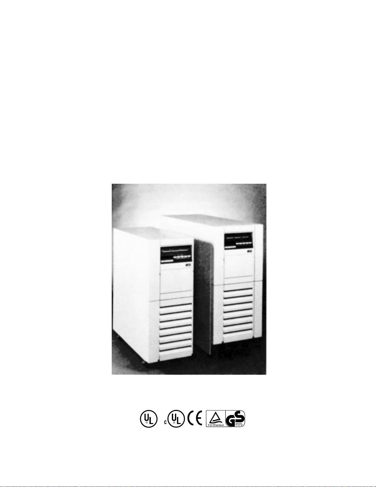
UNITY/I
User Manual
UT3K, UT4K, UT5K, and UT8K
Single-Phase Uninterruptible Power Systems
MLS-0350B-OL
Copyright 1994-1997, Best Power. All rights reserved.
å
Page 2

IMPORTANT SAFETY INSTRUCTIONS
SAVE THESE INSTRUCTIONS
IF THE UPS IS SOUNDING AN ALARMand you need to know what the alarm means and how to respond, turn to Section
204. To silence the audible alarm, press the [CANCEL] key.Silencingthe audible alarm does not correct the condition that caused
the alarm.
This manual contains important instructions for your UNITY/I UPS.
The installation and use of this product must comply with all national, federal, state, municipal or local codes that apply.If you
need help, please have your UPS model and serial number and call Best Power’s Worldwide Service at 1-800-356-5737 (U.S.A.
or Canada) or 1-608-565-2100. Outside of the U.S.A. and Canada, you can also call the nearest Best Power office for more
information.
Best Power
P.O. Box 280
Necedah, Wisconsin 54646 U.S.A.
Telephone: 1-608-565-7200
Toll-free: 1-800-356-5794 (U.S.A. and Canada)
FAX: 1-608-565-2221
International Fax: 1-608-565-7675
Worldwide Service, Best Power
P.O. Box 11
Necedah, Wisconsin 54646 U.S.A.
Telephone: 1-608-565-2100
Toll-free: 1-800-356-5737 (U.S.A. and Canada)
FAX: 1-608-565-7642
Best Power Technology Mexico, S.A. de C.V.
Golfo de Riga, 34
Colonia Tacuba
Mexico D.F. 11410
MEXICO
Telephone: (52)(5) 399-0369
FAX: (52)(5) 399-1320
Best Power Technology Pte. Ltd.
PICO Creative Centre, Level 5
20 Kallang Avenue
SINGAPORE 339411
Telephone: 65-2938122
FAX: 65-2968766
Sola Australia Ltd.
13 Healey Road
Dandenong Victoria 3175
AUSTRALIA
Telephone: 61-3-9706-5022
FAX: 61-3-9794-9150
Best Power Technology Limited
BEST House
Wykeham Industrial Estate
Moorside Road
Winchester
Hampshire
SO23 7RX
ENGLAND
Telephone: (44) 1962-844414
Toll-Free: 0800-378444
FAX: (44) 1962-841846
Best Power Technology GmbH
Am Weichselgarten 23
D-91058 Erlangen
GERMANY
Telephone: +49/9131/77700
Gebührenfrei: 0130/84/7712 (in Germany)
Fax: +49/9131/777050
Borri Elettronica Industriale Srl
Via dei Lavoratori, 124
20092 CINISELLO BALSAMO (Mi)
Milan, ITALY
Telephone: (39) 2-6600661-2
FAX: (39) 2-6122481
Best Power Technology AG
Limmatstrasse 12
8957 Spreitenbach
SWITZERLAND
Telephone: 056/418-30-30
FAX: 056/418-30-33
å
Page 3
CAUTION!
All uninterruptible power systems (UPS) units contain dangerous voltages.
The unit can provide power from its batteries. To avoid possible personal injury or equipment damage, assume that hazardous voltage is present at the unit’s output any time AC input power or DC
battery voltage is applied. To make certain there is no output voltage, turn the unit off, unplug the
unit, and disconnect all DC sources.
For units with line cords, the power supply cord is intended to serve as the disconnect device. The
socket-outlet shall be near the equipment and shall be easily accessible.
Before maintenance or repair, all connections must be removed. Before maintenance, repair, or
shipment, the unit must be completely switched off and unplugged or disconnected.
VORSICHT!
Vorsicht: Alle USV-Einheiten beinhalten gefährliche Spannungen.
Wenn der “Ein/Aus”-Schalter der USV eingeschaltet ist, kann an den Steckdosen der USV
gefährliche Spannung anliegen. Die Batterie der USV liefert selbst dann Strom, wenn die USV nicht
ans Netz angeschlossen ist.
Bei Modellen mit Netzstecker wird zum Abschalten des Geräts der Stecker aus der Steckdose gezogen; bei anderen Modellen muß der Wechselstrom-Trennschalter benutzt werden. Die Steckdose muß
sich in der Nähe des Gerätes befinden und bequem erreichbar sein.
Achtung: Vor einer Wartung oder Instandsetzung müssen alle Anschlußleitungen entfernt werden.
Vor einer Wartung, Instandsetzung oder Transport muß die USV komplett abgeschaltet und
abgesteckt werden.
å
Page 4

Table of Contents
Introduction . . . . . . . . . . . . . . . . . . . . . . . . . . . . . . . . . . . . . . . . . . . . . . . . . . . . . . . . . . . . . . . . . . . . . . . . . .1
001 Storing the UNITY/I UPS . . . . . . . . . . . . . . . . . . . . . . . . . . . . . . . . . . . . . . . . . . . . . . . . . . . . . . . . .1
002 If You Have a Question . . . . . . . . . . . . . . . . . . . . . . . . . . . . . . . . . . . . . . . . . . . . . . . . . . . . . . . . . . .1
100 Starting the UNITY/I UPS . . . . . . . . . . . . . . . . . . . . . . . . . . . . . . . . . . . . . . . . . . . . . . . . . . . . . . . . . . . .2
101 Startup . . . . . . . . . . . . . . . . . . . . . . . . . . . . . . . . . . . . . . . . . . . . . . . . . . . . . . . . . . . . . . . . . . . . . . . .3
102 Setting the Time and Date . . . . . . . . . . . . . . . . . . . . . . . . . . . . . . . . . . . . . . . . . . . . . . . . . . . . . . . . .5
200 Operation . . . . . . . . . . . . . . . . . . . . . . . . . . . . . . . . . . . . . . . . . . . . . . . . . . . . . . . . . . . . . . . . . . . . . . . . .7
201 Front Panel Lights . . . . . . . . . . . . . . . . . . . . . . . . . . . . . . . . . . . . . . . . . . . . . . . . . . . . . . . . . . . . . . .7
202 Front Panel Keys and Display . . . . . . . . . . . . . . . . . . . . . . . . . . . . . . . . . . . . . . . . . . . . . . . . . . . . . .8
203 Inside the Front Door . . . . . . . . . . . . . . . . . . . . . . . . . . . . . . . . . . . . . . . . . . . . . . . . . . . . . . . . . . . . .9
204 Alarms: What They Mean and What to Do About Them . . . . . . . . . . . . . . . . . . . . . . . . . . . . . . .10
º
205 If You Have an Extended Power Outage . . . . . . . . . . . . . . . . . . . . . . . . . . . . . . . . . . . . . . . . . . . . . .13
206 Shutting Down the UNITY/I . . . . . . . . . . . . . . . . . . . . . . . . . . . . . . . . . . . . . . . . . . . . . . . . . . . . . . .13
300 Parameters . . . . . . . . . . . . . . . . . . . . . . . . . . . . . . . . . . . . . . . . . . . . . . . . . . . . . . . . . . . . . . . . . . . . . . . .14
301 Displaying Parameters . . . . . . . . . . . . . . . . . . . . . . . . . . . . . . . . . . . . . . . . . . . . . . . . . . . . . . . . . . . .14
302 Changing Parameter Values . . . . . . . . . . . . . . . . . . . . . . . . . . . . . . . . . . . . . . . . . . . . . . . . . . . . . . . .15
303 Parameter Table . . . . . . . . . . . . . . . . . . . . . . . . . . . . . . . . . . . . . . . . . . . . . . . . . . . . . . . . . . . . . . . . .16
400 Maintenance and Service . . . . . . . . . . . . . . . . . . . . . . . . . . . . . . . . . . . . . . . . . . . . . . . . . . . . . . . . . . . . .20
401 Regular Maintenance . . . . . . . . . . . . . . . . . . . . . . . . . . . . . . . . . . . . . . . . . . . . . . . . . . . . . . . . . . . . .20
402 Worldwide Service . . . . . . . . . . . . . . . . . . . . . . . . . . . . . . . . . . . . . . . . . . . . . . . . . . . . . . . . . . . . . . .20
403 Accessing the Alarm and System Logs . . . . . . . . . . . . . . . . . . . . . . . . . . . . . . . . . . . . . . . . . . . . . . .21
500 Specifications . . . . . . . . . . . . . . . . . . . . . . . . . . . . . . . . . . . . . . . . . . . . . . . . . . . . . . . . . . . . . . . . . . . . .23
600 Options . . . . . . . . . . . . . . . . . . . . . . . . . . . . . . . . . . . . . . . . . . . . . . . . . . . . . . . . . . . . . . . . . . . . . . . . . .27
Appendix A: Remote Emergency Power Of (EPO) . . . . . . . . . . . . . . . . . . . . . . . . . . . . . . . . . . . . . . . . . . . . .29
Appendix B: Attaching the Stabilizer Bracket . . . . . . . . . . . . . . . . . . . . . . . . . . . . . . . . . . . . . . . . . . . . . . . . .30
Warranty . . . . . . . . . . . . . . . . . . . . . . . . . . . . . . . . . . . . . . . . . . . . . . . . . . . . . . . . . . . . . . . . . . . . . . . . . . . . .31
4/97
This manual is for units with ROM versions 1.06-1.08.
Page 5

Introduction
The UNITY/I™ UPS is easy to start and operate. Once you start the UPS, it provides continuous, computergrade power to your equipment. The UPS keeps you informed of its status with its front panel lights, four-digit
display, and audible signals (beeper). Using the display and front panel keys, you can display UPS information
and program some features.
This manual tells you how to start and operate the UNITY/I UPS. Begin with Section 100, “Starting the
UNITY/I UPS,” which will help you determine whether you need to do any installation before you start the
UPS.
001 Storing the UNITY/I UPS
If you are not going to use the UPS right away, store it between -20° and +40° Celsius (-4° to +104° F). If you
remove the batteries and store them separately, you can store the UPS at -20° to +60° Celsius (-4° to +140° F).
Batteries have a longer shelf life if you store them below 25° Celsius (77° F).Recharge stored batteries every
90 to 120 days.
002 If You Have a Question
Best Power is committed to outstanding customer service. Worldwide Service is happy to help you with your
problems or questions. A service technician is available 24 hours a day, 365 days a year. Just call Worldwide
Service or the nearest Best Power office, or send a fax to the Worldwide Service fax number. Please have your
unit’s serial number available when you call; this number is inside the front door of the UPS.
If you prefer to contact Best Power via computer, you can use Bulletin Board Service, CompuServe, or Best
Power’s World Wide Web site to get more product information.
Best Power’s toll-free Fax-on-Demand service is also available 24 hours a day to give you access to technical
notes and product information.
Worldwide Service: 1-800-356-5737 (U.S., Canada) or 1-608-565-2100
Worldwide Service FAX: 1-608-565-7642 or 1-608-565-2509
Bulletin Board Service 1-608-565-7424
CompuServe: Go BEST at any ! prompt.
World Wide Web Site: http:/www.bestpower.com
Fax on Demand: 1-800-487-6813 (U.S. and Canada)
1
Page 6

* The drawings in Figure 1 show a UT3K, UT4K or UT5K. The UT8K is similar in appearance.
2
100 Starting the UNITY/I UPS
If your UNITY/I UPS does not have an input line cord and plug, it is a hardwired unit and must be installed by a
qualified electrician (see the
UNITY
/I Installation Manual). After a qualified electrician has installed the UPS,
or if the UPS has an input plug, follow the instructions in this section to start the unit.
Make sure that the UPS is near the equipment it will protect. Leave at least 4 inches (100 mm) space on top of
and behind the UPS for ventilation. Do not put the UPS near a source of heat.
Make sure that the temperature is 0° to 40° Celsius (32° to 104° Fahrenheit) and the relative humidity is 0 to
95% without condensation. The air must be free of dust, chemicals that corrode or other contaminants. Air must
be free to move around the unit. The batteries’ service life is longer if the operating ambient temperature
stays below 25° C (77° F).
Front View* Back View*
Output
Receptacles
(optional)
Front Panel Lights,
Display, and Keys
Front Door
(Keyswitch and
Serial Number
Inside)
Serial Number
Main Output
Circuit Breaker
(some models)
Communication
Port
Line Cord
DC Port
Grounding
Terminal
Stabilizer
Bracket
Figure 1
Page 7
101 Startup
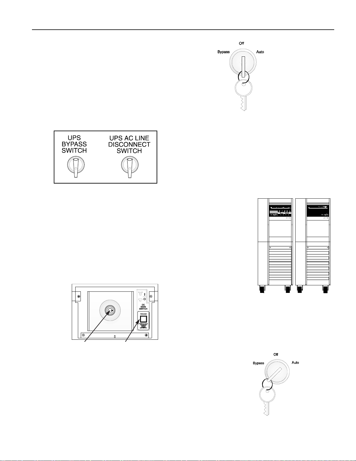
If you have a UT3K, UT4K or UT5K:Attach the stabilizer
1
bracket to the back of the UPS (see Appendix B).
Open the UPS’ front door by pulling the top of the door
2
toward you (see Figure 1 to find the door). Make sure that
the keyswitch inside the front door is turned to “Off” (see
Figure 2).
If your UNITY/I has an input line cord and plug:Plug in
3
the UPS. If the plug does not match the wall outlet, have a
qualified electrician install the proper wiring and outlet.
Figure 2
If your UNITY/I is hardwired (does not have an input line
cord and plug),an electrician should have installed the UPS.
An external bypass/AC disconnect switch should be mounted
on the wall nearby (see Figure 3). Turn the UPS AC LINE
DISCONNECT SWITCH to “ON” and the UPS BYPASS
SWITCH to “OFF.”
Figure 3
If you have an external battery pack(s)(see Figure 4), refer to the
4
installation instructions that came with your battery pack(s). Then continue
with the steps below:
a. After completing the battery pack installation, hold down the Precharge
switch on the front of the battery cabinet for five seconds (see Figure 5).
b. Insert the key into the main DC switch on the front of the battery
cabinet. Turn it clockwise, then pull the switch out toward you. The
ON-LINE light will light on the battery pack cabinet.
Keyswitch
Precharge Switch
UNITY/I
Figure 4
Battery Pack
Figure 5
Turn the keyswitch inside the front door of the UPS to “Auto” (see Figure
5
6). The yellow BATTERY light will turn on briefly, then the green LINE
light will turn on.
3
Figure 6
Page 8
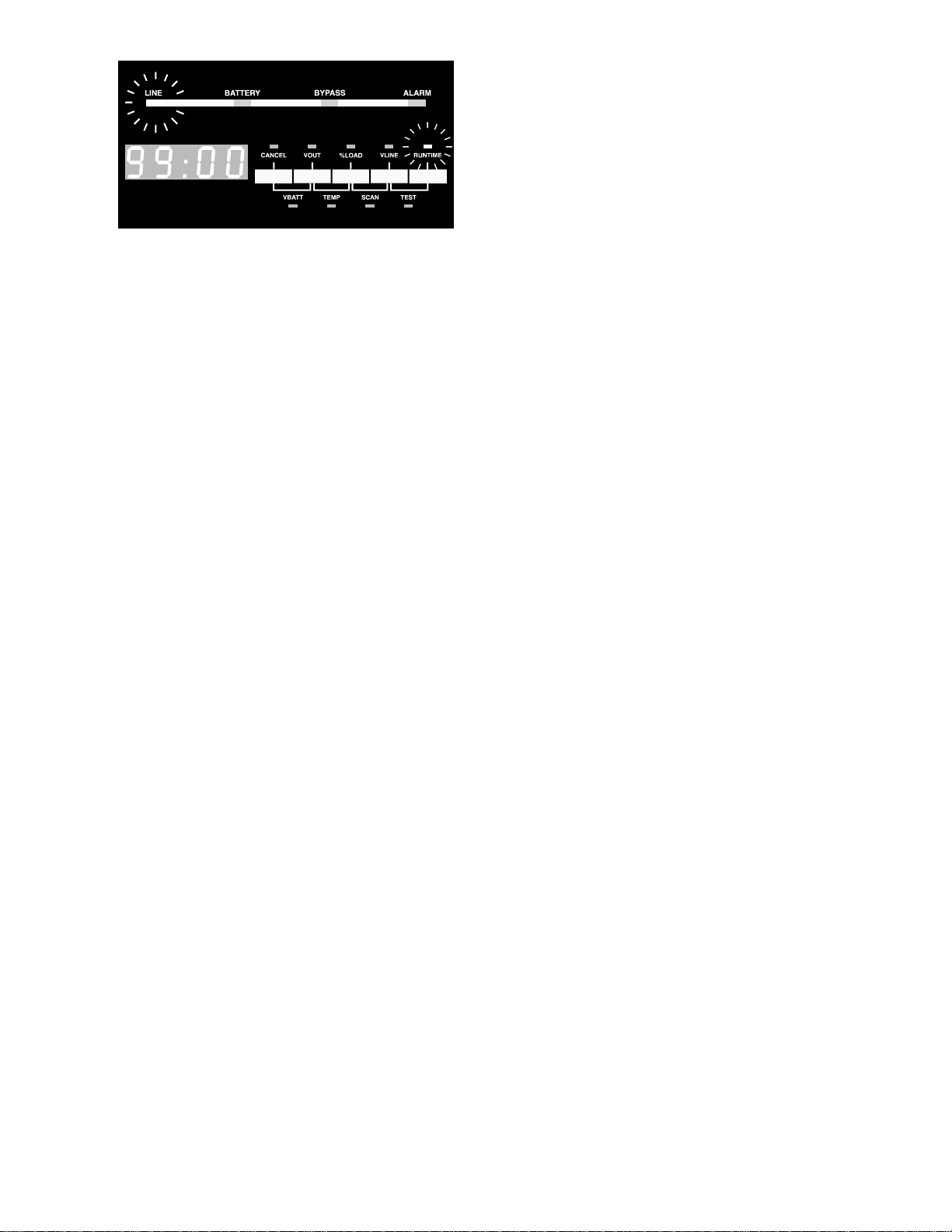
The four-digit display will show the estimated runtime
in minutes and seconds (see Figure 7). For now, the
estimated runtime is high because there is no equipment
drawing power from the UPS. If the red ALARM light
is on,see Section 204 before you go on.
Figure 7
Note:Do not continue until the green LINE light is on. The UPS is set at the factory to automatically select
its output frequency; to do this, the UPS mustrun on AC line. If the UPS does not run on ACline the
first time you start it, you must either set parameters 14 and 15 or wait until the green LINE light
comes on before you switch on the connected equipment. To set the parameters, see Section 302.
Once you switch on the unit and the LINE light comes on, the UPS will begin to charge the batteries. If this
6
is the first time you have started the UPS, let the UPS run on line for at least 24 hours to charge the
batteries. You may use the UPS right away; however, its battery runtime will be reduced until it fully
charges the batteries.
If your UNITY/I has receptacles on the back,switch off the equipment you want to connect to the UPS.
7
Then, plug the equipment into the receptacles on the back of the UPS and switch on the equipment. If the
red ALARM light comes on, see Section 204.
If your UNITY/I does not have receptacles on the back,the electrician who installed the UNITY/I should
have connected your equipment to it. Turn the UPS BYPASS SWITCH (see Figure 3) to “UPS.” Then,
switch on the equipment connected to the UPS. If the red ALARM light comes on, see Section 204.
The UNITY/I UPS is now providing continuous, computer-grade power to your equipment and is ready to
provide battery backup power when needed.
Note:You may occasionally hear short “clicking” sounds inside the unit; these clicks are a normal part of
unit operation.
If you plan to use CheckUPS software, connect the interface cable from the UPS to the computer system,
8
with the “UPS” end connected to the UNITY/I.
Using CheckUPS with Windows 95:Shut down your computer and insert the CheckUPS CD. Restart the
computer. Follow the instructions in the CheckUPS package.
Using CheckUPS withoutWindows 95:Start the computer and follow the instructions in the CheckUPS
package.
Fill out the warranty registration card in this manual and return it to Best Power. Please return the registra-
9
tion card within ten days of installation.
4
Page 9

102 Setting the Time and Date
The UPS stores the time, date, and year in parametersthat you can program (see Section 300 for more about
parameters). These parameters must be programmed correctly so that the UPS can store accurate information in
its alarm and system logs. Whenever the UPS has been shut down, you should reset the time and date after you
restart the UPS. To set the time, date, and year parameters, follow the steps below.
Note:When the unit is in parameter mode, the functions of the front panel keys change. The label inside the
front door of the unit explains what the keys do when the UPS is in parameter mode. The label also
shows a “Programming Template” with different key names for parameter mode.
1.To enter the parameter mode, hold down the [CANCEL] and [RUNTIME] keys together. Release the keys when
the display changes to P-00(for parameter 0).
2.Enter the user password (377) by following these steps:
a. Press [
b. Use the [%
CANCEL]. The display should show 0(the value of parameter 0).
LOAD] key to change the display to 377. If you accidentally scroll past 377, use the [VOUT]
key to go back.
Note:If you hold downthe [%
LOAD] or the [VOUT] key, the display will scroll more quickly after a few
seconds.
c. Press [
d. Press [
RUNTIME]. The display should show Ito show you have entered the user password.
CANCEL]. The display should show P-00.
3.Set the year (parameter 91) by following these steps:
a. Use the [%
b. Press [
LOAD] key to change the display to P-9I.
CANCEL]. The display should show a year.
c. Use the [%LOAD] orthe [VOUT] key to change the display to the correct year.
d. Press [RUNTIME]. The display should show the correct year.
e. Press [
CANCEL]. The display should show P-91.
Page 10

6
4. Set the date (parameter 90) by following these steps:
a. Use the [
VOUT] key to change the display to P-90.
b. Press [
CANCEL]. The display should show a date formatted as mm.dd (month.day).
c. Use the [%LOAD] or [VOUT] key to change the display reading to the correct month and day. For example, if
the date were March 27, you should enter “0327.”
d. Press [RUNTIME]. The display should show the correct date (mm.dd).
e. Press [
CANCEL]. The display should show P-90.
5. Set the time (parameter 89) by following these steps:
a. Use the [
VOUT] key to change the display to P-89.
b. Press [
CANCEL]. The display should show a time formatted as hh:mm (hour:minute).
c. Use the [%LOAD] or [VOUT] key to change the display reading to the correct time in 24-hour time. For times
from 1 p.m. to 11:59 p.m., add twelve to the hour. For example, 2:30 p.m. would be 14:30.
d. Press [RUNTIME]. The display should show the correct time (in 24-hour time).
e. Press [
CANCEL]. The display should show P-89.
6. To escape the parameter mode, press [
VLINE] twice.
Page 11

200 Operation
Once you start the UNITY/I UPS, it operates automatically. The UNITY/I keeps you informed of its status with
its front panel lights and four-digit display. If you wish, you can also use the front panel keys and four-digit display to view information about the UPS. In addition, the UPS has alarms that will alert you to UPS conditions
that require your attention.
201 Front Panel Lights
The lights on the front panel tell you several things about the operating status of the UPS. The four lights at the
top of the front panel are explained below. For an explanation of the nine small lights by the front panel keys,
see Section 202.
When the LINE light is off, the UPS is not receiving adequate AC input power to run on line (because of a
power outage or a severe power problem). In most cases, when the LINE light is off, the BATTERY light will
be on.
LINE Light (Green)
When the LINE light is on, the UPS is filtering and regulating
AC line power to provide computer-grade power to your equipment.
BATTERY Light (Yellow)
When the BATTERY light is on, the UPS is providing power
from its batteries.
BYPASS Light (Yellow)
When the BYPASS light is on, the unit is in internal bypass
mode. Either the front keyswitch has been turned to “Bypass,”
or parameter 63 has been enabled (see Section 300).
When the UPS is in bypass mode, it continues to power your connected equipment, but the UPS does not regulate the AC power going to the connected equipment, and the UPS will not provide battery backup power.
The UPS does continue to provide lightning protection, noise protection, and isolated output.
Note:If the BYPASS light is on even though the UPS keyswitch is turned to “Auto” and the unit is not indicat-
ing an A-16 alarm, the UPS may have automatically placed itself in bypass mode because it detected a
problem with its circuitry. Call Best Power’s Worldwide Service (see Section 402).
ALARM Light (Red)
When the ALARM light is on, the UPS is alerting you to an
alarm condition. See Section 204.
7
Page 12
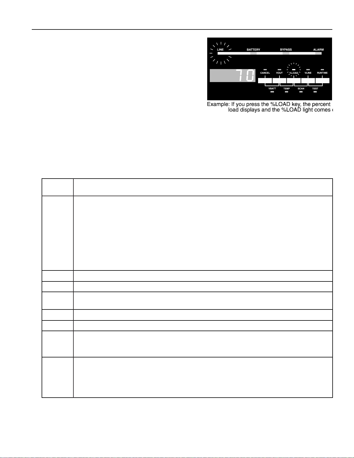
202 Front Panel Keys and Display
The front panel keys and four-digit display make it easy for
you to display information about the UPS.
The word above each key tells you what information the UPS
will display if you press that key. The words below the keys
tell you what information the UPS will display if you press the
two keys at the same time.
When you use the keys to display information, a small green
light near the key(s) you pressed lights to tell you what
information is currently displayed (Figure 8). The information
remains on the display until you press another key.
Table 1 explains what the keys do when the UPS is in its normal display mode. When you are displaying para-
meters or alarm and system logs, the keys have different functions; see Table 3 in Section 302 and Table 6 in
Section 403.
Table 1: Front Panel Key Functions (When parameters and logs are NOT displayed)
Figure 8
Key(s)
Pressed
CANCEL Silences any alarm that is currently sounding. If the UPS detects a new alarm condition later, it will restart
%LOAD Displays the percentage of the UPS’ total power capacity that your equipment is using.
VLINE Displays the AC input line voltage that the UPS is presently receiving.
RUNTIME Displays the estimated runtime remaining (in minutes and seconds). Note:The runtime display is most
VBATT Displays the present battery voltage (nominal is 48 V).
TEMP Displays the internal ambient temperature of the UPS in degrees Celsius.
SCAN Starts the scan mode. In scan mode, the UPS scrolls through a display of VBATT, VOUT, TEMP, %LOAD,
Result
the alarm beep. Silencing an alarm does not correct the condition that caused it (see Section 204).
Cancels a battery test if one is in progress.
Holding the key down for two seconds clears an alarm. The alarm will restart if the condition that caused
it still exists.
If the UPS has shut down because of an alarm condition, holding the key down for two seconds restarts the
UPS ifthe problem that caused the alarm has been solved and the unit is not in bypass mode.
accurate when the UPS is running on battery power.
VLINE and RUNTIME. Each value displays for two seconds, and the small green lights tell you which value
is currently displayed.
TEST Holding down this pair of keys for two seconds starts a test of the front panel lights (except BYPASS) and
four-digit display. Note: If Parameter 77 (Test on Demand) is enabled, the unit will also test the batteries. If
parameter 77 is enabled and parameter 62 (Nominal Input Voltage) is set, the unit will also test the BYPASS
light by briefly switching to internal bypass mode. See Section 300.
8
Page 13
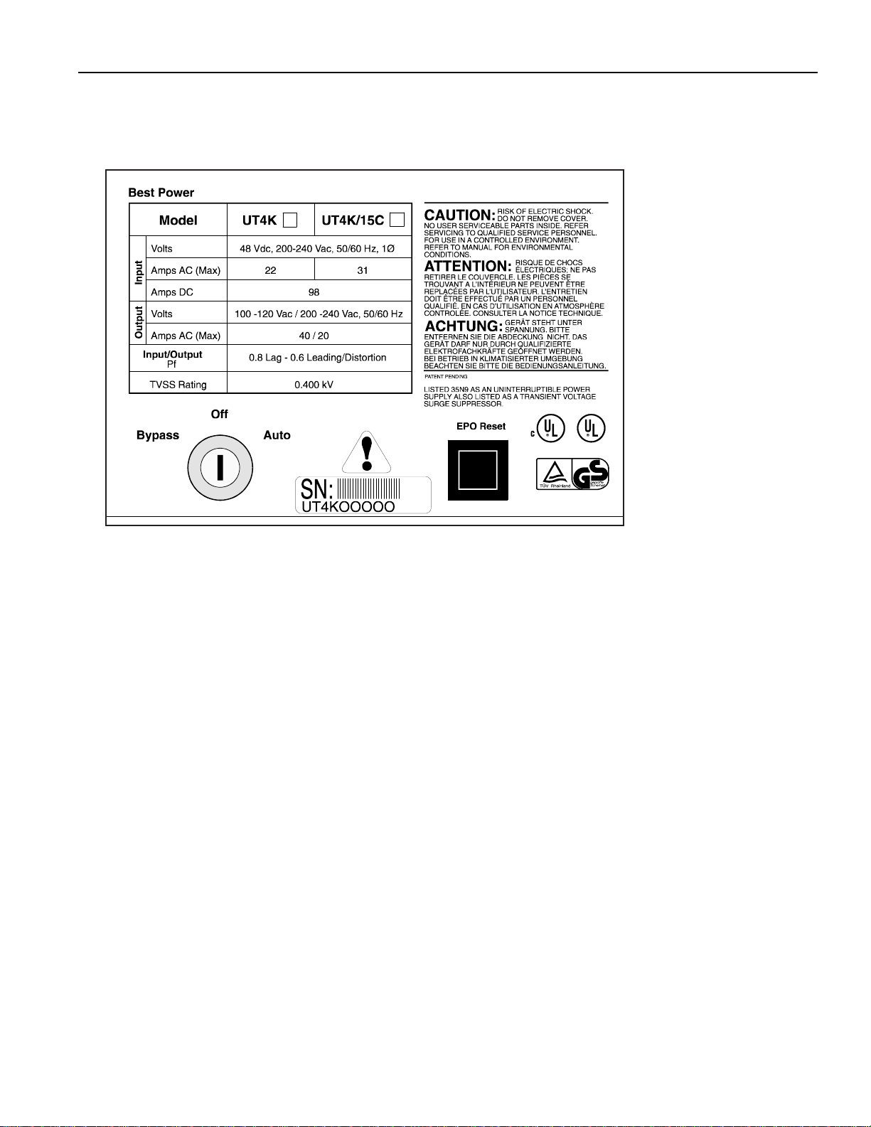
203 Inside the Front Door
The UPS’ front door is below the front panel keys (see Figure 1 in Section 100). To open the door, pull the top
of the door toward you. The keyswitch and Emergency Power Off (EPO) reset button are inside the front door.
In addition, the labels inside the door contain useful reference information. See Figure 9.
Figure 9
The Keyswitch
Using the keyswitch, you can put the UPS in auto mode, shut the unit off, or put the unit in internal bypass
mode.
• Auto: When the keyswitch is turned to “Auto,” the UPS provides computer-grade power to your
equipment. Usually, the UPS operates on AC line power, filtering and regulating utility
power. When necessary, the UPS switches to battery power.
• Off: When the keyswitch is turned to “Off,” the UPS is off and does not provide power to the
connected equipment. See Section 206 for information on completely shutting down the
UPS.
• Bypass:When the keyswitch is turned to “Bypass,” the unit provides power to your connected
equipment, but the UPS does not regulate this power, and the UPS cannot provide battery
backup power. However, the UPS does provide lightning protection, noise protection, and
isolated output.
The EPO Reset Button
If the UPS shuts down because of an Emergency Power Off (EPO) signal sent to its communication port,
use this button to restart the unit. After an EPO shutdown, the UPS' four-digit display scrollsEPO. The
EPO reset button does not serve as a reset button for any other purpose. See Appendix A for more
information on EPO.
Page 14

204 Alarms: What They Mean and What to Do About Them
The UNITY/I alerts you to some UPS conditions. If the UPS
detects an alarm condition, it:
• lights the red ALARM light.
• sounds an audible alarm.
• shows an alarm code on the four-digit display
(see Figure 10).
Codes A-08 (Low Battery) and A-16 (Auto Bypass) are not
alarm conditions. When either of these codes are displayed,
the red ALARM light will not be on and the UPS will not
sound an audible alarm.
Here’s how to react:
Figure 10
1. If you want to silence the audible alarm,press and release the [
CANCEL] key. Note that silencing the audible
alarm does not correct the condition that caused it; the ALARM light stays lit to remind you that the alarm
condition still exists. If the UPS detects a new alarm condition, it will sound a new audible alarm.
2. Read the alarm code(s) on the four-digit display. If more than one alarm condition exists, the four-digit dis-
play will show each alarm code, one at a time. If the display shows a dot moving from right to left, press any
of the front panel keys to display the alarm code(s).
3. Find the alarm(s) in Table 2. The table tells what the alarm means and gives a possible solution. If the table
tells you to phone Best Power’s Worldwide Service, phone the nearest Best Power office (in the U.S.A. and
Canada, call 1-800-356-5737). Please have the UPS serial number available when you call; you will find this
number inside your unit’s front door. Call from a telephone that is as near the UPS as possible.
Table 2: Alarms
What to DoWhat It MeansAlarmAlarm
Code
A-00
Low Runtime
The UPS is running on battery
power and the runtime remaining
is low. (At the factory, the UPS is
programmed to sound this alarm
when 2 minutes of runtime are
left). The UPS display switches
between the alarm code (a-00)
and the estimated runtime.
Do an orderly shutdown of your equipment. You do
not need to shut off the UPS. The UPS will
automatically shut itself down, but it will leave its
microprocessor on. This means that when adequate
AC input power returns, the UPS can automatically
restart and begin to recharge its batteries (unless
you have set Parameter 03 to disable the auto restart
feature).
A-01
Overload
Your equipment is drawing more
power than the UPS is designed
to provide.
10
Press the [%LOAD] key. Shut off the equipment
connected to the UPS one piece at a timeuntil the
%LOAD display shows 100 or less. Remove the
equipment that you shut off. If you need help, call
Best Power’s Worldwide Service or the nearest Best
Power office.
Page 15

Table 2: Alarms (continued)
Alarm
Code
A-02
A-03
A-04
A-05
Alarm What It Means What to Do
Circuit Breaker
Warning/Shutdown*
High Ambient
Temperature
Check Battery
Check Inverter
There is a high output
current from the UPS. This
usually happens because the
equipment connected to the
UPS is overloading it.
The temperature inside the
UPS is high.
The UPS has detected a
possible problem with the
batteries.
The UPS has detected a
possible problem with the
inverter.
The UPS will shut down. Shut off all of the equipment
connected to the UPS. Then, restart the UPS by holding
down the [CANCEL] key for two seconds. Next, press
the [%LOAD] key. Then, watch the %LOAD display as
you switch on the load equipment one piece at a time.
Once the %LOAD reaches “100,” the unit is fully loaded
and you should not start any additional equipment
connected to the UPS. If you need help, call Best Power’s
Worldwide Service or the nearest Best Power office.
If you can identify a source of heat outside of the UPS
(such as an unusually high room temperature), correct the
cause of the high temperature. Also, make sure that nothing outside the UPS is blocking the vents on the front and
back of the unit. If the alarm continues, phone Best
Power’s Worldwide Service or the nearest Best Power
office.
Phone Best Power’s Worldwide Service or the nearest
Best Power office. If you have an external battery cabinet,
first make sure that the DC switch on the battery cabinet
is switched on.
Phone Best Power’s Worldwide Service or the nearest
Best Power office.
A-06
A-07
* In this case, “Circuit Breaker” does not refer to the circuit breaker(s) on the output receptacles panels of some UNITY/I
models. Instead, the alarm refers to the UPS’ software-controlled overcurrent protection, which operates like a circuit
breaker.
Memory Error
High Battery
On startup, the unit has
failed its automatic memory
test.
Battery voltage is too high.
There may be a problem
with the parameter settings,
batteries, or charging
circuit.
Shut the unit down and restart it. If the alarm sounds
again, hold down the Cancel key for about 3 seconds. If
the alarm does not stop, phone Best Power’s Worldwide
Service or the nearest Best Power office; the UPS must be
recalibrated.
Phone Best Power’s Worldwide Service or the nearest
Best Power office.
11
Page 16

Table 2: Alarms (continued)
Code
What to DoWhat It MeansAlarmAlarm
A-08
A-09
A-10
A-12
A-13
Low Battery
(Advisory Condition)
Check Fan
Tap Regulator Alarm
Low AC Out
Shutdown
Battery voltage is too low for
the UPS to operate on battery
power.
The fan inside the UPS is not
functioning properly.
There is a problem inside the
unit.
The UPS AC output voltage is
low.
Before this code is displayed, you should have
received a “00” (Low Runtime) alarm to warn
you to shut down your equipment. When acceptable AC input power returns, the UPS will automatically restart (unless you have set parameter
03 to disable the auto restart feature). When the
UPS restarts, it will temporarily run in a bypass
(nonregulating) mode (see A-16). Codes A-08
and A-16 will display until the battery voltage
returns to above 48VDC for 2 minutes.
Runtimes will remain low until the unit fully
recharges the batteries.
Phone Best Power’s Worldwide Service or the
nearest Best Power office.
——Reserved
Phone Best Power’s Worldwide Service or the
nearest Best Power office. Note:If the UPS
begins running on battery power, monitor the
runtime so that you may do an orderly shutdown
of your equipment if runtime gets low.
Phone Best Power’s Worldwide Service or the
nearest Best Power office.
A-14
A-15
A-16
A-17
A-18
A-19
High AC Out
Warning/Shutdown
Check MOVs
Auto Bypass
(Advisory Condition)
Check Fuse Board
Reserved
Check Power Supply
The UPS AC output voltage is
high.
The UPS has detected a problem
with a MOV (Metal Oxide
Varistor) inside the unit.
The UPS is in internal bypass
mode. If AC line is present, the
UPS continues to provide power
to the connected equipment, but
it does not regulate the power
going to the connected equipment, and it will not provide
battery backup power.
The UPS has detected a possible
problem with the fuse board.
—
The unit has detected a possible
problem with the internal power
supply.
The UPS will shut down. Phone Best Power’s
Worldwide Service or the nearest Best Power
office.
Phone Best Power’s Worldwide Service or the
nearest Best Power office.
If the UPS also has an A-08 alarm,see A-08,
Low Runtime, in this table.
If the UPS is in internal bypass (battery
maintenance) modebecause parameter 63 has
been enabled, the UPS will display A-16 until
you reset parameter 63 to “0.”
Phone Best Power’s Worldwide Service or the
nearest Best Power office.
—
Phone Best Power’s Worldwide Service or the
nearest Best Power office.
12
Page 17
205 If You Have an Extended Power Outage
If a power outage lasts a long time, the UNITY/I continues to provide power for your equipment until it reaches
the end of its runtime. You can check how much runtime remains by pressing the [
panel. At a set number of minutes before the end of the runtime (factory default is two minutes), the UPS sounds
a “Low Runtime” alarm (A-00). When the UPS gives this alarm, do an orderly shutdown of your equipment.
However, do not shut off the UPS. The UPS will shut itself down, but it will leave its microprocessor on. As
soon as normal AC line power returns, the UPS will automatically restart itself (unless you have set parameter
03 to disable the auto restart feature) and begin recharging its batteries. If you know that the power outage will
be long (for example, a day or longer), you may wish to shut down the UPS. See Section 206.
RUNTIME] key on the front
206 Shutting Down the UNITY/I UPS
Usually, you do not need to shut down the UPS, even if your equipment will be shut down for several days.
There may be times, however, when you want to shut down the UPS, such as when you will not be using the
UPS for an extended period of time, when the UPS is being serviced, or before you move the UPS. Best Power
does not recommend shutting down the UNITY/I on a daily basis.To shut down the unit, follow the instructions
below.
Note:While the UPS is shut off, recharge the batteries every 90 to 120 days. You can do this by restarting the
UPS for 24 hours.
1. If your UNITY/I does not have an external bypass switch,switch off the protected equipment.
If your UNITY/I has a “Break Before Make” external bypass switch(the words above the UPS BYPASS
SWITCH read, in this order, “LINE” “OFF” “UPS”), turn off the protected equipment. Then, turn the UPS
BYPASS SWITCH to “LINE.” Switch the protected equipment back on.
CAUTION
Before switching an external make-before-break (MBB) bypass switch to the LINE position, the BYPASS
light on the UPS front panel must be lit. If you operate an external MBB bypass switch while the UPS is
operating on line power or on battery power, equipment damage may result. Refer to Best Power
publication “TIP 410” for proper bypass switch operating instructions.
If your UNITY/I has a “Make Before Break” external bypass switch(the words above the UPS BYPASS
SWITCH read, in this order, “LINE” “UPS” “OFF”): Turn the UPS BYPASS SWITCH to “LINE.”
2. Turn the keyswitch inside the unit’s front door to “Off.”
3. If your UPS does not have an external bypass switch,disconnect the UPS by shutting off its circuit breaker
or by unplugging the UPS. Shutting off the circuit breaker is preferred, but if other pieces of equipment are
connected to the same breaker, you may want to leave the breaker on and unplug the UPS.
If your UPS has an external bypass switch,turn the UPS AC LINE DISCONNECT SWITCH to “OFF.”
4. If you have an external battery pack, push in the main DC switch on the front of the cabinet.
5. When you are ready to restart the UPS, follow the entire startup procedure in Section 100.
Page 18

300 Parameters
The UPS uses some of its parameters to keep track of information, operating conditions, and power conditions.
Other parameters allow you to program some of the unit’s features. This section explains how to display and
change some UNITY/I parameters.
301 Displaying Parameters
This section explains how to display parameters using the front panel keys and four-digit display. The table in
Section 303 contains more information about what many of the parameters mean.
Note:When the unit is in parameter mode, the front panel keys have different functions. See the label inside the
UPS front door for an explanation of the key functions in parameter mode. The label also shows a
“Programming Template” with different key names for parameter mode.
1. To enter the parameter mode, hold down the [CANCEL] and [RUNTIME]keys together for two seconds. Release
the keys when the four-digit display changes to P-00.
P-00is a parameter number. The first column of the parameter table in Section 303 contains the parameter
numbers.
2. Whenever a parameter number (P-XX) is displayed, you can use the following keys to go to the parameter
that you wish to display:
• Press [%
• Press [VOUT] to go back to the previous parameter number.
Note:To scroll through the parameter numbers quickly, hold downthe [%LOAD] or [VOUT] key.
3. Press [CANCEL] to display the parameter’s value. Example: Parameter 7 is the Low Runtime Alarm setpoint.
To display the setpoint, first display parameter 7 by following steps 1 and 2 above. Then, with P-07on the
display, press [
when two minutes of runtime are left. The parameter table in Section 303 describes the information you can
find in some UNITY/I parameters.
4. Press [
between the parameter number and parameter value.
5. If you wish to display additional parameters, repeat steps 2-4.
6. To escape parameter mode, press [VLINE] twice.
LOAD] to go to the next parameter number.
CANCEL] to display the value. If the value is 2, the UPS will sound a Low Runtime alarm
CANCEL] to return to the parameter number (P-XX). Note that the [CANCEL] key allows you to switch
14
Page 19

302 Changing Parameter Values
You can set some of the parameter values to program certain UPS features. The table in Section 303 describes
many of the parameters.
Make sure that you FULLY understand a parameter before you try to change the value. If you set certain
parameters improperly, the UPS may not operate correctly.
1. Hold down the [CANCEL] and [RUNTIME] keys at the same time for two seconds. Release the keys when the
display changes toP-00. Then, press [
2. As the table in Section 303 shows, you will need a password to change parameters. The user password is
377. To enter it, follow the steps below.
CANCEL]. The display should show 0.
a. Use the [%
Note: To scroll the display more quickly, hold downthe [%
b. Press [
LOAD] orthe [VOUT] key to change the display to 377.
LOAD] or [VOUT] key.
RUNTIME] to enter the password. The display should read I(for password level 1).
You may now change parameters that require a user password. For password requirements, see the third
column of the parameter table in Section 303.
Note: If no keys are pressed for five minutes, the UPS password level goes back to level “0,” and you
must re-enter the user password.
3. Press [
CANCEL] to return to the parameter number display (P-XX). Note that the [CANCEL] key lets you
switch between the parameter number and parameter value.
4.Use the [%
LOAD] orthe [VOUT] key to go to the parameter that you wish to change. Then press [CANCEL] to
display the parameter value.
5.Whenever a parameter value is displayed, use these keys to change the setting:
• Press [%LOAD] to increase the setting.
• Press [VOUT] to decrease the setting.
Note: In step 1, you entered the user password. If a parameter requires a higher password for changes, the
UPS will not let you change that parameter.
6.To enter the new value, press [RUNTIME]. The UPS beeps to confirm that the new value has been entered. If
you wish notto save a change that you have made, press [VLINE] and the value will remain at its original
setting.
7.If you wish to change additional parameters, repeat steps 3-6.
8.To escape parameter mode, press [VLINE] twice.
Page 20

Table 3 explains what each of the keys does when a parameter number or parameter value is displayed.
Table 3: Parameter Mode Key Functions
Key Programming
Template Key Name
When a Parameter
Numberis Displayed
When a Parameter Valueis Displayed
CANCEL # Switches to the parameter
value.
VOUT — Goes back to the previous
parameter number.
%LOAD + Goes to the next parameter
number.
VLINE ESC Escapes parameter mode. Returns to the parameter number display without
RUNTIME
5
This key has no function
when the parameter number
is displayed.
Switches to the parameter number.
Decreases the parameter setting.
Returns to the parameter number display without
saving any changes made to the parameter value.
saving any changes made to the parameter value.
Enters the new parameter setting.
303 Parameter Table
The parameter table, Table 4, explains many of the unit’s parameters. See Sections 301 and 302 for information
on displaying and changing parameters.
Note: Some parameters are not listed. These parameters are used only in special circumstances or are intended
to help qualified service personnel troubleshoot, adjust, and calibrate the UPS.
Table 4: Parameters
Parameter
Number
P-00
P-03
P-05
P-07
P-13
Parameter
Name
Password None
Auto
Restart
Nominal
Output
Voltage
Low
Runtime
Alarm
Setpoint
Frequency
Password Level
Required to
Change Setting
User
User
User
Change not
allowed
Sample
Parameter
Value
0
1
240
2
60.0
Parameter Description
Allows you to enter a password. See Section 302.
When the UPS shuts itself down, this parameter determines
whether the UPS restarts automatically. If set to “1,” the UPS
restarts itself when conditions allow. If set to “0,” you must
manually restart the UPS by turning the keyswitch to “Off”
and back to “Auto.” Choices:0 (Disable) or 1 (Enable).
Sets the nominal output voltage. This setting should equal the
output voltage wired at the factory or by your electrician. Call
Best Power’s Worldwide Service or the nearest Best Power
office before you try to change this setting. Range of values:
180-260.
If the UPS is running on battery power, it sounds a Low
Runtime alarm (A-00) when the amount of battery runtime
remaining (in minutes) is equal to or less than this value.
Range of values:1-99.
The frequency that the UPS is now supplying to your
equipment.
16
Page 21

Table 4: Parameters (continued)
Parameter
Number
P-14
P-15
P-16
P-17
P-26
Parameter
Name
Nominal
Frequency
Auto
Frequency
Enable
Maximum
Frequency
Minimum
Frequency
PhonTek
TM
Copies
Password Level
Required to
Change Setting
User
User
User
User
User
Sample
Parameter
Value
1
1
65.0
45.0
0
Parameter Description
If parameter 15 = 0, this parameter allows you to choose
the unit’s nominal output frequency. If the UPS is in
auto frequency mode (parameter 15 = 1), this parameter
shows the nominal frequency that the unit has selected.
Choices:0 (50 Hz) or 1 (60 Hz).
Enables auto frequency mode if set to “1.” In auto
frequency mode, the UPS automatically selects the
nominal frequency based on the input frequency.
Choices:0 (Disable) or 1 (Enable). Note:If auto
frequency mode is enabled, the unit automatically
selects the frequency, then automatically resets the
maximum frequency (parameter 16) to the auto-selected
frequency + 3 Hz and resets the minimum frequency
(parameter 17) to the auto-selected frequency – 3 Hz.
Sets the maximum input frequency for operation on AC
line. The value must be greater than the nominal
frequency (see parameters 14 and 15). Range of values:
50.5-65.0. Note:If you manually set maximum
frequency, disable auto frequency mode (parameter 15).
Sets the minimum input frequency for operation on AC
line. The value must be less than the nominal frequency
(see parameters 14 and 15). Range of values:45.0-59.5.
Note:If you manually set minimum frequency, disable
auto frequency mode (parameter 15).
In units with software version 1.04 or higher, this
parameter starts PhonTek transmission and sets the
number of copies to be sent. If you need to use PhonTek,
Best Power’s Worldwide Service will provide more
instructions. Range of values:0-98 copies.
99 = continuous.
P-33
P-34
P-35
Runtime
Percent
Load
Power
Factor
Change not
allowed
Change not
allowed
Change not
allowed
15:00
70
1.00
The estimated battery runtime (in minutes and seconds).
When the UPS is running on battery power and this
value reaches a preset limit (see parameter 07), the UPS
sounds a Low Runtime alarm (A-00). Note:The
estimated runtime display is most accurate when the
UPS is running on battery power.
The percent of the UPS’ total capacity that the
connected equipment is currently using.
The power factor of your equipment (the difference in
the way it draws voltage and current). Power factor =
kW out (parameter 36) divided by kVA out (parameter
37). Note:If no load equipment is applied to the UPS,
parameter 35 shows “0.00.”
17
Page 22

Table 4: Parameters (continued)
Parameter
Number
P-36
P-37
P-50
P-62
P-63
Parameter
Name
kW out Change not
kVA out Change not
Beeper
Enable
Nominal
Input Voltage
Battery
Maintenance
Mode
Password Level
Required to
Change Setting
allowed
allowed
User
User
User
Sample
Parameter
Value
4.00
4.00
1
0
0
Parameter Description
The total power (in kilowatts) that your equipment is drawing
from the UPS.
The total “apparent power” (in kilovolt-amperes) that your
equipment is drawing from the UPS.
This parameter lets you enable or silence allpresent and
future audible alarms and the “on battery power” beep.
Choices:0 (Silence) or 1 (Enable).
This parameter sets the UPS for the proper nominal input
voltage when you use parameter 63. Note:If parameter 62 is
set and parameter 77 is enabled, the UPS will test the
BYPASS light during a front panel key TEST (see Section
202). Range of values:200-240.
Setting this parameter to “1” puts the UPS into battery
maintenance mode. In this mode, the UPS continues to power
the connected equipment but does not regulate the power
going to the connected equipment and will not provide
battery backup power.The unit does continue to provide
noise protection, lightning protection, and isolated output. See
parameter 62 before setting parameter 63. Choices:0
(Disable) or 1 (Enable). This parameter is meant to be used
during battery maintenance. Battery maintenance must be
done by qualified service personnel only.For help, phone
Best Power’s Worldwide Service or the nearest Best Power
office.
P-89
P-90
P-91
P-92
P-93
P-128
Time
Date
Year
System
Hours
System Years
Software
version
User
User
User
Change not
allowed
Change not
allowed
Change not
allowed
0:00
1.01
1997
1
0
1.08
The time of day in 24-hour time, formatted as hh:mm
(hour:minute). Range of values:0:00-23:59.
The date formatted as mm.dd (month.day). Range of values:
1.01-12.31.
The year. Range of values:1994-2130.
The number of hours the system has operated. Changes to “0”
every 8760 hours (1 year). See also parameter 93.
The number of years the system has operated.
The ROM version.
18
Page 23

BATTERY TEST PARAMETERS (Parameters 73-77)
During a battery test, the UPS shuts off the battery charger, waits two seconds, and checks the battery voltage. If the UPS detects low battery voltage, it stops the test and starts a Check Battery alarm (A-04). If battery voltage is not low, the UPS switches itself to battery power for a set length of time (parameter 75). If the
UPS detects a possible weak battery, it switches back to AC line power and starts a Check Battery alarm (A-
04). You can tell the UPS how often to test the batteries (parameter 74) and at what time of day (parameter
73). You can also program the UPS to “test on demand” (parameter 77), which allows you to test the batteries
on demand by pressing the front panel TESTkeys. If you prefer, you can tell the UPS not to perform a periodic battery test (parameter 76). See Sections 301 and 302 for more information on displaying and changing
parameter settings.
Note:If the UPS microprocessor loses power (because, for example, the unit is switched off), the battery test
parameters will return to their factory default settings.
Table 4: Battery Test Parameters
Parameter
Number
Parameter
Name
Password Level
Required to
Change Setting
Parameter
Value
Parameter DescriptionSample
P-73
P-74
P-75
P-76
P-77
Battery Test
Time
Interval
Length
Battery Test
Demand
User
UserBattery Test
UserBattery Test
UserFirst Day of
UserTest on
0.00
7
15
0.00
0
The time of day (in 24-hour time) that the battery test
begins. Make sure that you also set the Time (parameter
89). Range of values:00:00-23:59.
The number of days between battery tests. Range of
values:1-28.
The length of time that the UPS runs on battery power
during the battery test, expressed as a percentage of the
Low Runtime alarm setpoint (parameter 07). For example, the default Battery Test Length is 15% of 2 minutes
(P-07 default), which equals 0.3 minutes (18 seconds).
Range of values:5-25.
The date on which the first battery test will start, formatted as mm.dd (month.day). Make sure that you also set
the Date (parameter 90). Setting parameter 76 to
“0.00” disables the periodic battery test.Range of values:0.00 (Disable periodic battery test) or 01.01-12.31
(Date of first test).
If this parameter is set to “0,” it disables two parts of the
front panel key TEST: the battery test, and the internal
bypass test. If this is set to “1,” you can test the batteries
on demand by pressing the front panel TEST keys. See
Section 202 for a complete description of the front panel
key TEST. Choices:0 (Disable) or 1 (Enable).
19
Page 24

400 Maintenance and Service
This section discusses what kind of maintenance the UNITY/I UPS needs, tells how to contact Best Power’s
Worldwide Service, and explains how to read the unit’s alarm and system logs.
401 Regular Maintenance
Best Power designed the UNITY/I UPS to provide years of trouble-free operation. You will probably find that the
UNITY/I requires less maintenance than your other computer peripherals. Nevertheless, the UPS does require
some attention in order to provide you with excellent service. Best Power recommends that you schedule a
Preventative Maintenance check at least every six months. At this check, a qualified technicianshould inspect
and clean the unit, check the batteries, check the AC and DC meter functions, and perform a power outage test.
Important safety precautions must be observed while performing these checks.For more information on
Preventative Maintenance checks, or to schedule a Preventative Maintenance with a Best Power-authorized field
service representative, call Best Power’s Worldwide Service. We’ll be happy to help you.
402 Worldwide Service
Best Power has an outstanding customer service department. Please feel free to call or write if you have a
problem or question about your UNITY/I UPS. When you call or write, please have the following information
available:
• The UPS model number and serial number (inside the front door of the unit).
• A brief description of the problem or question.
Note: In some cases, the phone technician may ask you to access information from the unit’s software
parameters. If possible, call from a telephone that is near the UPS.
Before returning a unit for any reason, contact the nearest Best Power office for instructions and an RMA (Return
Materials Authorization) number.
In the U.S.A. and Canada, call Best Power’s Worldwide Service at 1-800-356-5737.Elsewhere, contact the
nearest Best Power office. Customers anywhere can call 1-608-565-2100 to reach Best Power’s Worldwide
Service.See the inside front cover of this manual for the telephone numbers and addresses of Best Power offices.
In the U.S.A., send correspondence to:
Worldwide Service
Best Power
P.O. Box 11
Necedah, Wisconsin 54646 U.S.A.
FAX: 1-608-565-7642
20
Page 25

403 Accessing the Alarm and System Logs
The UNITY/I stores information in two logs: the alarm log and the system log. The alarm log stores the 16 most
recent alarm conditions. The system log stores up to 20 UPS events. You can use the logs to keep track of UPS
events, and a technician can use the logs to help troubleshoot the UPS. This section explains how to access and
read the alarm and system logs using the unit’s front panel keys and four-digit display.
Note:When you display the alarm and system logs, the front panel keys have different functions. Table 6
below explains what the keys do when you are displaying the alarm and system logs. (The keys have
similar functions when you display parameters; see Table 3 in Section 302 and the Programming
Template inside the unit’s front door.)
Table 6: Key Functions While Displaying Alarm and System Logs
Key Programming
Template Key Name
CANCEL # Switches between the log number and the information in the log entry.
VOUT — When a log number is displayed, this key goes back to the previous log
%LOAD + When a log number is displayed, this key goes to the next log number.
VLINE ESC Escapes to parameter 00 (P-00).
Key Function (while viewing alarm and system logs)
number.
RUNTIME 5 This key has no function while the logs are displayed.
To access and read the UPS alarm and system logs, follow the instructions below.
1. Simultaneously hold down the [
CANCEL] and [RUNTIME] keys. Release the keys when the display shows P-
00.
2. Press [
3. Press [%
VOUT]. The display should show PI34.
LOAD]. The display should show AL I. (If your UPS has never had an alarm condition, the display
should show SL I.)
Notes:ALstands for “alarm log.” The unit stores a maximum of 16 alarm events.
SLstands for “system log.” The unit stores a maximum of 20 system events.
The lower the log number, the more recent the log entry. Log “1” is the most recent entry. Once the alarm or
system log is full, the newest entry is added as log number “1” and the oldest entry is dropped.
4. With the log number ALXX or SLXX displayed, you can use the [%
LOAD] and [VOUT] keys to step up and
down through the log numbers. If you step past the last system log entry (to P-00), repeat steps 2 and 3 to
display the logs again.
21
Page 26
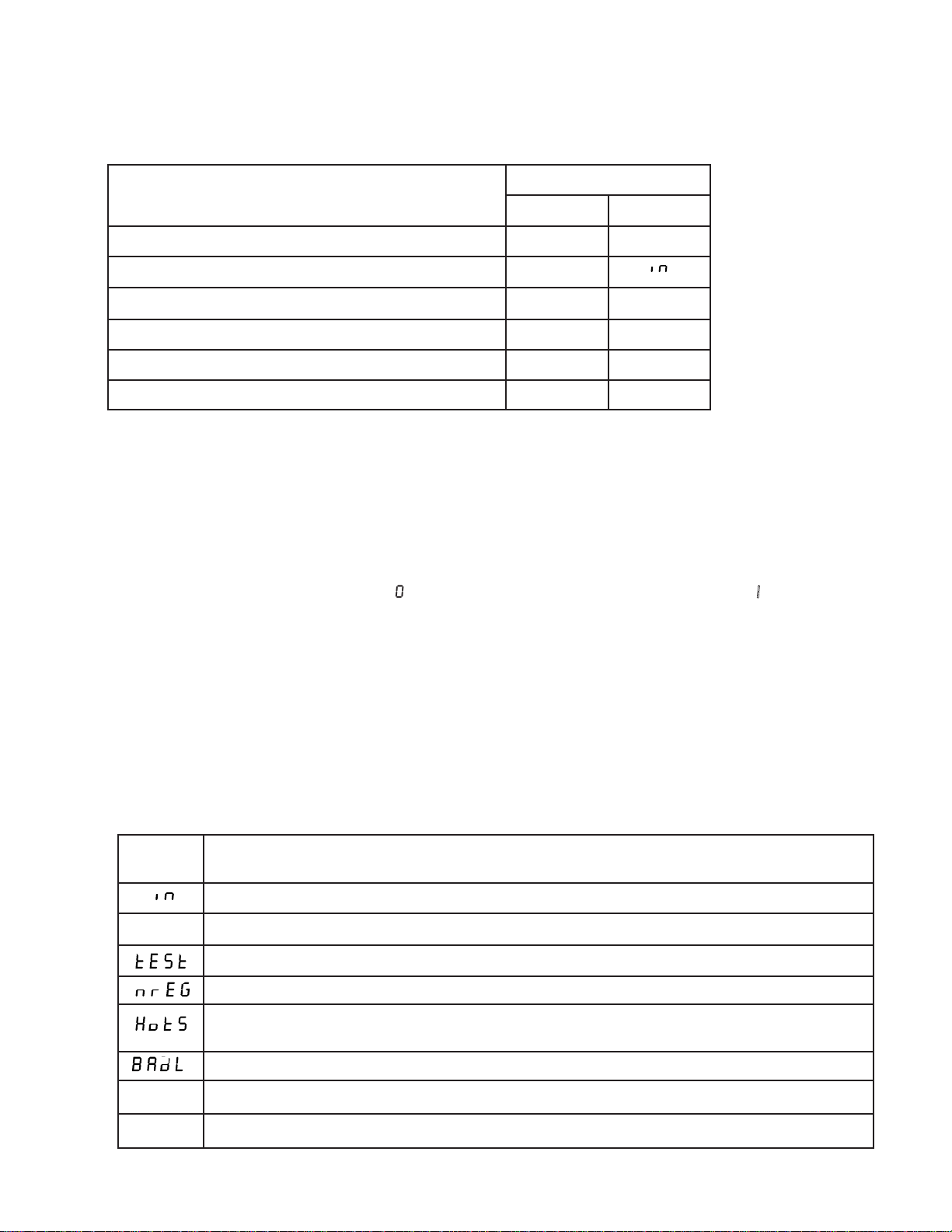
5. Once you have accessed the log number that you wish to display (for example, SL I), press the [CANCEL] key to
display the information in that log entry. The display will scroll through the six pieces of information shown in
Table 7 below.
Table 7: Information in the Alarm and System Logs
Sample DisplayInformation in Log Entry
Alarm Log System Log
Log number
Event code (alarm code or system event code)
1
2
AL 4 SL 20
a 00
Date that the event began (month and day, mm.dd)
Year that the event began
Time that the event began (in 24-hour time)
Length of the event (in hours and minutes, hh:mm)
1
If an event is currently active, the log number display will show a decimal point after the “AL” or “SL” (i.e., a display of
AL. Iindicates that the event recorded in Alarm Log 1 is active).
2
For alarm codes, see Section 204. For system event codes, see the table below.
3
A display of 0means that the event duration was less than one minute. A display of ----means that the event lasted
more than 18 hours, 12 minutes (18:12).
3
01.25 01.25
1997 1997
13:21 13:07
00:01 00:15
In the table above, the sample logs read as follows:
• AAlarm LLog 44: The unit had an
II33::22II
(
• SSystem LLog
II999977
6. Press [
). The alarm lasted for one minute (
2200
:The unit ran on inverter (battery power) beginning on January 25, 1997 (
) at 1:07 p.m. (
CANCEL] to return to the log number. Then, repeat steps 4 and 5 to display other log entries.
II33::0077
AA 0000
alarm beginning on January 25, 1997 (
0000::00II
).
). The unit ran on inverter for 15 minutes (
0011..2255 II999977
0000::II55
).
) at 1:21 p.m.
0011..2255
7. To escape the alarm and system logs, press [VLINE] twice.
Table 8: System Log System Event Codes
Displayed
Code
SLP
EPO
OFF
What It Means
The UPS ran on battery power (inverter).
The UPS shut down, but the microprocessor stayed active (also referred to as “sleep” mode).
The UPS did a battery test.
The unit was not regulating power (for example, after a Low Battery shutdown).
The unit was placed into battery maintenance mode (see parameter 63), or the unit tested the BYPASS
light by briefly switching to internal bypass mode during a front key TEST (see Section 202).
Corrupted log.
The UPS shut down due to an Emergency Power Off signal sent to the unit’s DB9 port.
The unit’s keyswitch was turned off, or the unit sounded a Check Power Supply alarm (A-19).
22
Page 27

500 Specifications
Table 9: Specifications (Standard Product)
Model Number UT3K UT4K UT5K UT8K
Capacity 3 kVA/3 kW 4 kVA/4 kW 5 kVA/5 kW 8 kVA/8 kW
Nominal ACInput Voltage
AC Input Current
200 V input
208 V input
220 V input
230 V input
240 V input
AC Input Frequency
Efficiency on AC Line
2
3
17 amps
17 amps
16 amps
15 amps
14 amps
4
5
95% 96% 96% 96%
200, 208, 220, 230, 240
22 amps
22 amps
20 amps
20 amps
19 amps
50/60 Hz ±3 Hz.
28 amps
27 amps
25 amps
24 amps
23 amps
45 amps
43 amps
41 amps
39 amps
38 amps
Maximum Heat Output (on
AC Line)
Audible Noise on AC Line at
539 BTU/hour
0.158 kW/hour
569 BTU/hour
0.167 kW/hour
711 BTU/hour
0.208 kW/hour
40 dBA
1 meter
Typical Runtime
Full Load:
75% Load:
50% Load:
Weight
(with Batteries)
Dimensions
(H x W x D)
1
For UT5K units with an optional L6-30 input plug and 200 V input, capacity is 4.55 kVA/ 4.55 kW.
6
19 minutes
26 minutes
43 minutes
215 lbs.
98 kgs.
12 minutes
17 minutes
28 minutes
280 lbs.
127 kgs.
9 minutes
13 minutes
21 minutes
295 lbs.
134 kgs.
29 in. x 10.5 in. x 25.75 in.
737 mm x 267 mm x 654 mm
For UT5K units with an optional L6-30 input plug and 208 V input, capacity is 4.75 kVA/4.75 kW.
2
The unit will operate on AC line at input voltages of 147 V to 276 V (at the default parameter settings).
3
For models with a standard battery charger.
4
Programmable range is 45 to 65 Hz. See Sections 302 and 303, parameters 16 and 17.
5
At 75% resistive load, batteries at full charge.
6
At 0.75 power factor.
1138 BTU/hour
0.333 kW/hour
13 minutes
19 minutes
31 minutes
490 lbs.
222 kgs.
32 x 13 x 33 in.
813 x 330 x 838 mm
AC Output
Voltage Regulation: Regulates steady state output voltage to ±5% of nominal on line and on battery at the
default parameter settings. Exceeds the CBEMA voltage regulation guideline for computing
equipment under any line, load or battery condition, excluding bypass mode.
Sine Wave Power: Provides sine wave, computer-grade power with five percent or less total harmonic
distortion at full resistive load on battery power. Meets or exceeds CSA C22.2 No. 107.1.
Output wave form is essentially the same as line on AC line.
23
Page 28

Output Frequency: 50 Hz or 60 Hz ±0.15 Hz on battery. Same as line on AC line within programmable limits.
(See Section 303, parameters 13-17).
Output Protection:Provides automatic current and overvoltage protection. The unit has high AC and low AC
output voltage alarms, as well as circuit breaker warning/shutdown and overload alarms.
Optional output receptacle panels protected by fuses or circuit breakers.
Lightning, Surge, and Noise Protection
Lightning/Surge Protection: Passes ANSI/IEEE C62.41 Categories A3 (6000 volt, 200 amp ring-wave test)
and B3 (6000 volt, 500 amp ring-wave and 6000 volt, 3000 amp combinationwave). UL 1449 listed. Meets IEC 801-5. Zero Surge Clamping Response Time.
Surge Voltage Let-Through: 0.7% of peak (typical) in ANSI/IEEE C62.41 1991 Category A3 test.
Surge Suppressor Rating: 300 Joules.
Noise (RF) Isolation: Advanced, compound filter elements provide up to 90 dB attenuation in normal
mode from 100 KHz to 10 MHZ and up to 50 dB attenuation in common mode
from 100 KHz to 10 MHZ.
Isolation: Input isolated from output. Output neutral bonded to ground.
Environment
Ventilation: Air around the UPS must be free of dust, chemicals, or other materials that corrode or conta-
minate. Air must be free to move around the UPS. Do not place the UPS in a sealed room or
container.
Operating Environment:0° to + 40° Celsius (+32° to +104° F). 0 to 95% relative humidity (noncondensing).
Battery service life is longer if the operating temperature stays below 25° Celsius
(77° F).
High Altitude Operation:The maximum operating ambient temperature drops 1° Celsius per 300 meters (2°
Fahrenheit per 1000 feet) above sea level, with the maximum operating elevation
being 3000 meters (10,000 feet).
Storage Temperature: Batteries: -20° to +40° Celsius (-4° to +104° F). UPS without batteries: -20° to +60°
Celsius (-4° to +140° F).
24
Page 29

Batteries and Battery Charger
Batteries: Batteries are sealed, maintenance-free, gas recombinant, lead-acid type, specially designed for
UPS use. Nominal battery voltage is 48 VDC. Batteries are UL 924 recognized.
Battery Charger:The standard battery charger is a three-state charger (Maintenance, Constant Current and
Constant Voltage). Recharge time to 85% is 4 to 6 hours typical.
Third Party Compliance and Standards
Safety/EMC Compliance:UL listed, cUL listed to Canadian standards, TÜV/GS certified, FCC Part 15: Class
A (includes Class A limits specified in the Radio Interference Regulations of the
Canadian Department of Communication), Vfg 243/1991, Vfg 46/1992, CISPR 22.
Applicable Standards: UL 1778, UL 1449, CSA Standard C22.2 No. 107.1-M91, BSI EN 60950, EN
50082-2, EN 50091-1.
Communication Connections
DB 9 Port Pinouts (Default Settings)
Contacts consist of isolated open collector circuits capable of switching up to 40 VDC 50 mA resistive load.
Table 10: Specifications for Models with Optional 380/400/415 VAC Input
Pin Function
1
RS232 RD:The UNITY/I receives data at the programmed baud rate (default is 1200
baud), 8 bits, no parity, 1 stop bit, and no handshaking.
2
RS232 TD:The UNITY/I transmits data at the programmed baud rate (default is 1200
baud), 8 bits, no parity, 1 stop bit, and no handshaking.
3 Inverter Normally Open Contact:Closes to indicate that the UPS is on battery power
(programmable contact 1).
4 Common:Signal ground for all interface signals and contacts.
5 Low Runtime Normally Open Contact:Closes to indicate that battery runtime is low
(programmable contact 0).
6 Inverter Normally Closed Contact:Opens to indicate that the UPS is on battery
power (programmable contact 2).
7 Remote Emergency Power Off:Short to ground to turn the UPS off. Apply +12
VDC to turn the UPS back on or connect to Pin 8 (current limited).
8 Unregulated +18 VDC Nominal Source:An unregulated +18 VDC nominal source
protected by a 1000 ohm source impedance.
9 Internal Bypass Normally Open:Closes to indicate that the UPS is in internal bypass
mode. (Note:Does not close for the A-16 condition that occurs after a low battery
shutdown. See Section 204.)
25
Page 30

26
Specifications: Models with Optional 380/400/415 VAC Input
Specifications for models with optional 380/400/415 VAC input are the same as for standard models except for
the following:
Table 11: Specifications for Models with Optional 380/400/415 VAC Input
1
The unit will operate on AC line at input voltages of 280 V to 524 V (at the default parameter settings).
2
For models with a standard battery charger.
3
At 75% resistive load, batteries at full charge.
Model Number UT3K UT4K UT5K UT8K
Nominal AC Input
Voltage
1
380, 400, 415
AC Input Current
2
380 V Input
400 V input
415 V input
9.1 amps
8.6 amps
8.3 amps
12 amps
11 amps
11 amps
15 amps
14 amps
13 amps
24 amps
23 amps
22 amps
Efficiency on AC
Line
3
92%
Maximum Heat
Output (on AC Line)
891 BTU/hour
0.260 kW/hour
1186 BTU/hour
0.347 kW/hour
1485 BTU/hour
0.434 kW/hour
2377 BTU/hour
0.695 kW/hour
Weight with Batteries 242 lbs.
110 kgs.
322 lbs
146 kgs.
337 lbs.
153 kgs.
546 lbs.
248 kgs.
Page 31
600 Options
Best Power offers a number of options for the UNITY/I. The list below describes these options. If you would
like more information, please contact the nearest Best Power office or dealer.
Bypass Switches:
If your UPS does not have a plug, an external bypass switch lets you conveniently transfer your protected
equipment to direct AC input power when the UPS needs service. The nearest Best Power office can tell you
if an external bypass switch is recommended for your UPS.
Environmental Monitoring:
EnviroCom™ I monitors many UPS and environmental conditions and phones you when there is a problem.
Extended Runtime:
If you want extended runtime, call Best Power for information on adding additional battery capacity.
Interface Kits:
For computers that include their own UPS monitoring and shutdown software, Best Power offers interface
cables and assemblies for a number of computer systems. These let your computer’s software shut down
your protected equipment safely during an extended power outage.
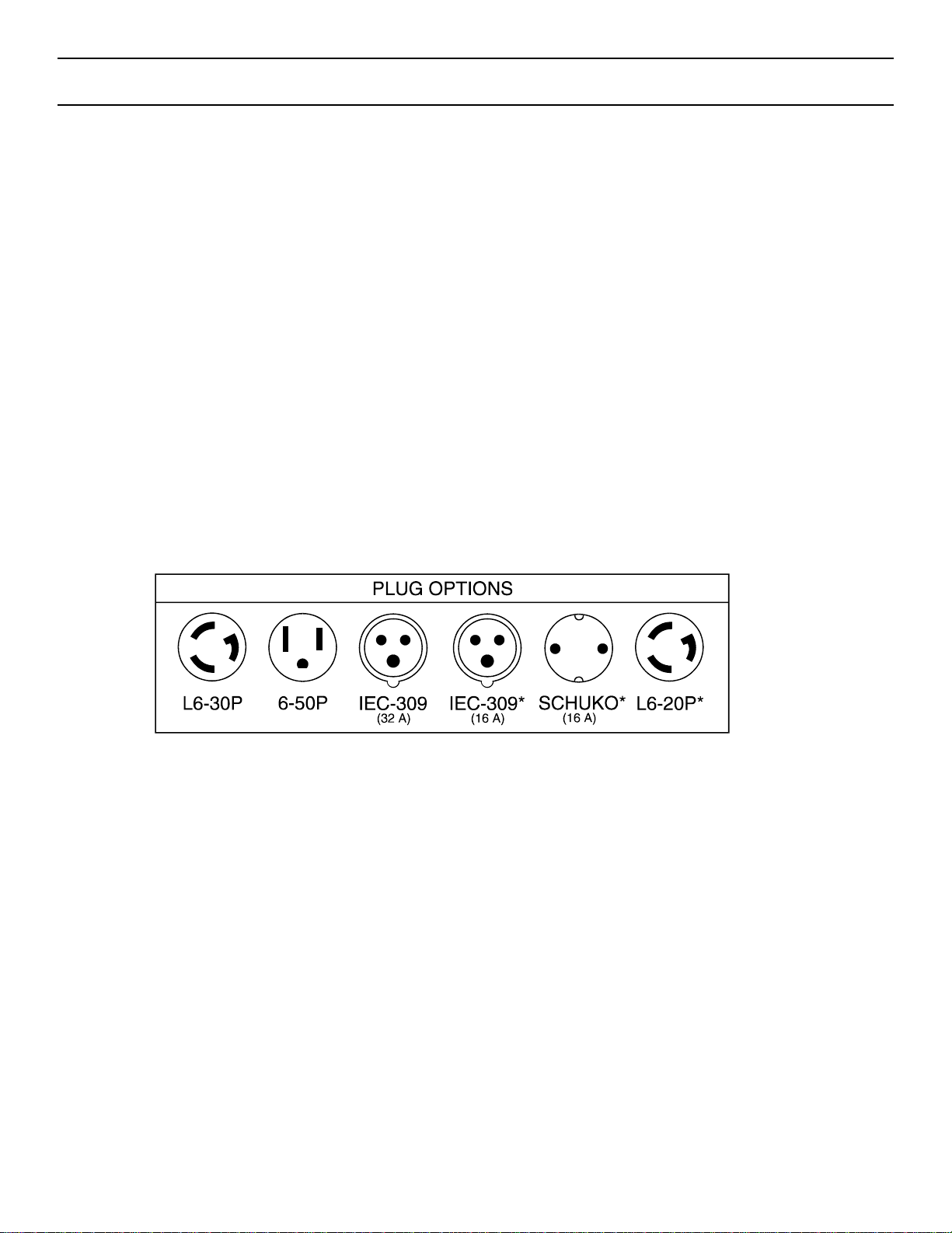
Plugs:
The following input plugs are available for new UT3K*, UT4K and UT5K units:
* IEC-309 (16 A), SCHUKO, and L6-20P plugs available on UT3K only.
Figure 11
27
Page 32
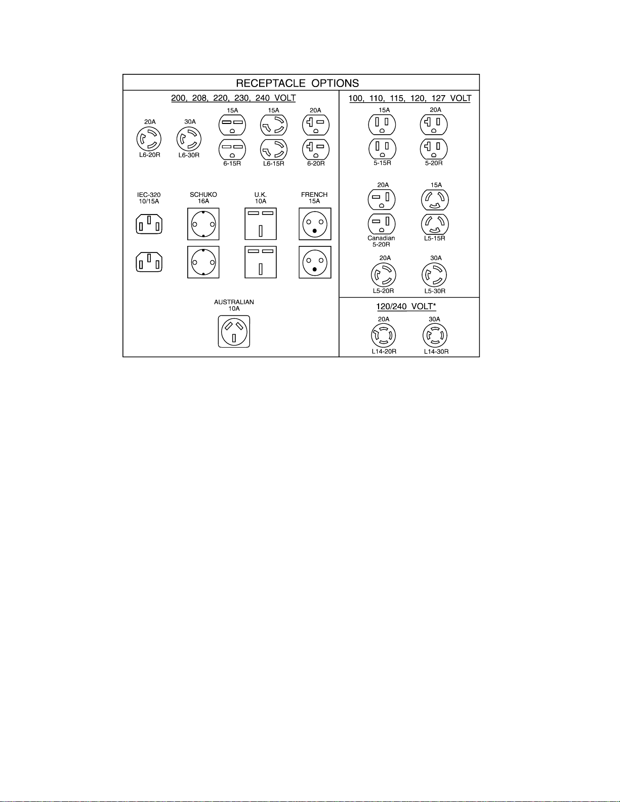
Receptacles:
The following output receptacles are available for new units:
*L14-20R and L14-30R available for 120/240 volts only.
Figure 12
Warranties:Besides the standard two-year warranty, Best Power offers Warranty Enhancement Plans to meet
your service and maintenance needs. Call the nearest Best Power office for more information.
28
Page 33
Appendix A:Remote Emergency Power Off (EPO)
Computer rooms often have an emergency shutdown switch (sometimes referred to as a “panic button”). This
switch shuts off the power that runs the equipment in the computer room. If the UPS’ AC input source is connected to the switch, the switch will shut off the inputpower to the UPS. However, the UPS will interpret this
as a power outage and will continue to provide outputpower to the equipment it protects until its batteries run
down. To make sure that your emergency shutdown switch can shut off the UPS’ outputpower, use the unit’s
remote Emergency Power Off (EPO) feature.
CAUTION
Shut down the UPS (see Section 206) and disconnect AC power to the UPS before making connections to
the UPS’ communication port.
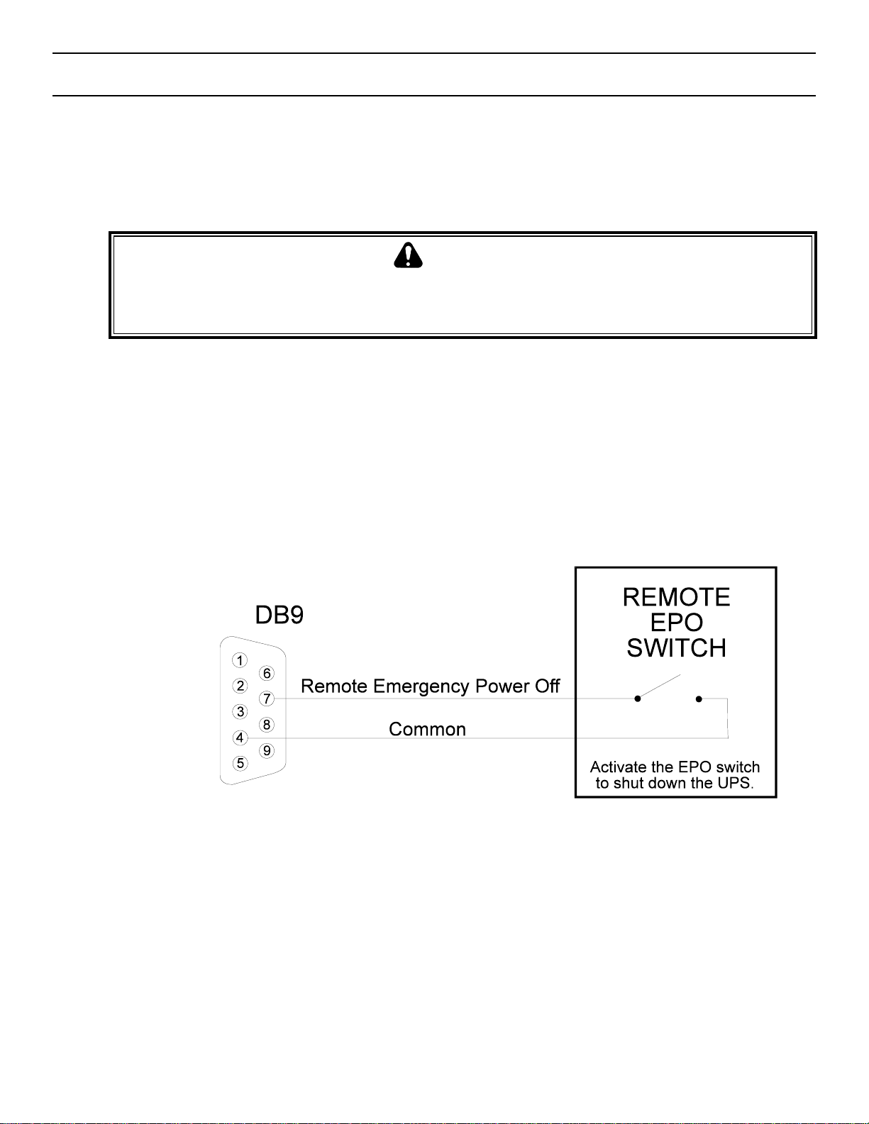
• Your computer room’s emergency shutdown switch must have a set of dedicatedcontacts that can short pin 7
to pin 4 on the UNITY/I unit’s communication port. Use a shielded, single twisted pair cable to connect the
emergency shutdown switch to the UPS communication port. See Figure 11.
• When the UPS’ pin 7 is shorted to pin 4, the UPS’ outputpower is shut off. When an EPO shutdown of the
UPS occurs, the UPS scrolls EPO on its four-digit display.
• To restart the UPS after an EPO shutdown, press the EPO Reset Button inside the front door of the UPS.
NOTE: The UPS cannot be restarted if the EPO signal is still asserted on pin 7.
Figure 13
29
Page 34
Appendix B: Attaching the Stabilizer Bracket
A stabilizer bracket is included with all UT3K, UT4K, and UT5K units. Installation of the stabilizer bracket is
required to meet TÜV requirements, per standards EN 60 950 and EN 50091-1.
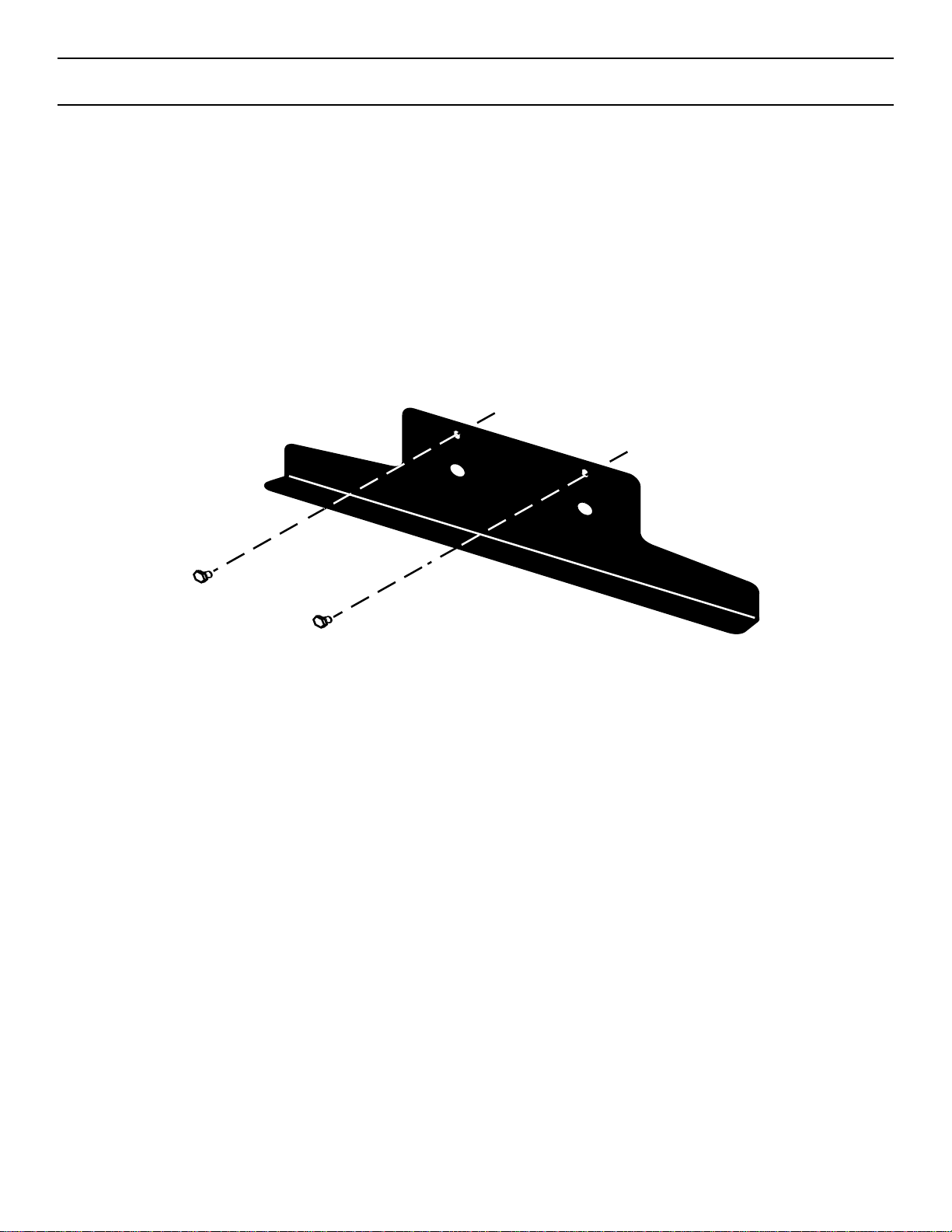
To attach the stabilizer bracket, follow the instructions below.
1. The UPS is easier to move without the stabilizer bracket attached, so first move the UPS to its permanent location.
2. Place the stabilizer bracket flat against the back panel of the UPS. The base of the stabilizer bracket will rest
on the floor.
3. Use the bolts to secure the brackets to the UPS (see Figure 14).
Figure 14
30
Page 35

31
Warranty
LIMITED TWO YEAR WARRANTY
Standard Warranty For All Purchases
BEST POWER, a division of General Signal Power Systems, Inc. (“BEST POWER”) warrants that each product
sold by BEST POWER is compatible with existing commercially available computer equipment with enclosed
power supplies and is free from defects in materials and workmanship under normal use and service. This
warranty is applicable only to the initial retail purchaser (PURCHASER), and is not transferable. The duration
of this warranty is two (2) years from the date of the first retail sale or the date of delivery to the PURCHASER,
whichever occurs first, subject to the following conditions.
If the PURCHASER discovers within the duration of this warranty a failure of the product to perform
compatibly with presently existing computer equipment or a defect in material or workmanship, the
PURCHASER must promptly notify BEST POWER in writing within the duration of the warranty or not later
than one month after expiration of the warranty. BEST POWER’s obligation under this warranty is limited to the
replacement or repair, subject to the conditions specified below, of such product returned intact to BEST
POWER which shall appear to BEST POWER, upon inspection, to have been either incompatible or defective.
Replacement or repair will be made at BEST POWER’s Worldwide Service, Highway 80, Necedah, Wisconsin
54646, U.S.A. Such repair or replacement shall be at BEST POWER’s expense. This warranty does not cover
any taxes which may be due in connection with replacement or repair, nor any installation, removal,
transportation or postage costs. These expenses will be paid by PURCHASER. If BEST POWER is unable to
repair or replace the product to conform to this warranty after a reasonable number of attempts, BEST POWER
will refund the purchase price. Remedies under this warranty are expressly limited to those specified above.
TO THE EXTENT ALLOWED BY LAW, BEST POWER DISCLAIMS ALL OTHER WARRANTIES,
EXPRESS OR IMPLIED, INCLUDING, BUT NOT LIMITED TO, ANY IMPLIED WARRANTIES OF
MERCHANTABILITY OR FITNESS FOR A PARTICULAR PURPOSE, AND ANY IMPLIED WARRANTY
OF MERCHANTABILITY OR FITNESS FOR A PARTICULAR PURPOSE ON THIS PRODUCT IS
LIMITED IN DURATION TO THE DURATION OF THIS WARRANTY. TO THE EXTENT ALLOWED BY
LAW, BEST POWER SHALL NOT BE LIABLE FOR ANY SPECIAL, INCIDENTAL, OR
CONSEQUENTIAL DAMAGES INCLUDING, BUT NOT LIMITED TO, LOSS OF PROFITS, INJURIES TO
PROPERTY, LOSS OF USE OF THE PRODUCT OR ANY ASSOCIATED EQUIPMENT.
Some states do not allow limitations on how long an implied warranty lasts, so that the above limitation on
duration of implied warranties may not apply to you. Some states do not allow the exclusion or limitation of
incidental or consequential damages, so the above limitation or exclusion may not apply to you. This warranty
gives you specific legal rights, and you may also have other rights which vary from state to state. You are
advised to consult applicable state laws.
No warranty is made with respect to other products sold by BEST POWER which do not bear the name BEST
POWER, and no recommendation of such other product shall imply or constitute any warranty with respect to
them. This warranty does not cover repair or replacement because of damage from unreasonable use (for example only, damage from road hazard, accident, fire or other casualty, misuse, negligence, or incorrect wiring) and
any use or installation not in conformance with instructions furnished by BEST POWER, or repairs or replacements needed because of modifications or parts not authorized or supplied by BEST POWER.
Page 36

32
LIMITED WARRANTY
Transient Voltage Surge Suppression Circuitry
(For U.S. and Canadian Purchasers Only)
BEST POWER, a division of General Signal Power Systems, Inc. (“BEST POWER”) hereby warrants the transient
voltage surge suppression circuitry in each FERRUPS®, FORTRESS®, PATRIOT®, UNITY/I™, CITADEL®, or
SPIKEFREE
TM
product (hereinafter called “Product”) sold by it for installation in the United States of America and
Canada to be free from defects in material and workmanship under normal use and service for the lifetime of the
Product, beginning with the date of sale to the initial retail purchaser, subject to the following conditions. This
warranty is applicable only to the initial retail purchaser (hereinafter called PURCHASER), is not transferable, and
is limited to the following remedies:
1. The replacement or repair of the transient voltage surge suppression circuitry in each Product that is returned
intact to BEST POWER and which shall appear to BEST POWER upon inspection to have been defective in
material or workmanship or to have been damaged through normal use;
2. The reimbursement to the PURCHASER of up to $25,000 per occurrence of documented physical damage to
specified computer equipment connected to a Product where such damage could have been prevented by
transient voltage surge suppression circuitry as detailed in BEST POWER’s specification for the Product sold.
This warranty is made in addition to BEST POWER’s Limited Two Year Warranty.
This warranty does not include any taxes which may be due in connection with replacement or repair nor any
installation, transportation or postage costs. These expenses will be paid by PURCHASER. Replacement or repair
will be made at BEST POWER’s Worldwide Service, Highway 80, Necedah, Wisconsin 54646, U.S.A.
This warranty does not cover repair or replacement because of damage from unreasonable use (damage from road
hazards, accident, fire or other casualty, misuse, negligence, incorrect wiring) and any use or installation not in
conformance with instructions furnished by BEST POWER, or repairs or replacements needed because of
modifications or parts not authorized or supplied by BEST POWER.
This warranty is operable only upon the written acceptance by BEST POWER of an application by the
PURCHASER on BEST POWER’s standard form for the above warranty coverage for the Product sold. In such
application, the PURCHASER shall represent that the Product sold has been properly installed and grounded in
accordance with instructions received from BEST POWER, and the PURCHASER shall also specify the computer
equipment to which the Product sold has been connected and the location of the computer equipment. This
warranty will not apply to any equipment not specified in the application by the PURCHASER as protected
equipment.
EXCEPT AS EXPRESSLY SET FORTH IN THIS WARRANTY AND BEST POWER’S LIMITED TWO YEAR
WARRANTY, BEST POWER MAKES NO OTHER WARRANTIES, AND TO THE EXTENT ALLOWED BY
LAW, BEST POWER DISCLAIMS ALL OTHER WARRANTIES, EXPRESS OR IMPLIED, INCLUDING, BUT
NOT LIMITED TO, ANY IMPLIED WARRANTIES OF MERCHANTABILITY OR FITNESS FOR A
PARTICULAR PURPOSE.
REMEDIES UNDER THIS WARRANTY ARE EXPRESSLY LIMITED TO THE REPAIR OR REPLACEMENT
OF PRODUCTS AND THE REIMBURSEMENT SPECIFIED ABOVE, AND TO THE EXTENT ALLOWED
BY LAW ANY CLAIMS FOR LOSS ARISING OUT OF THE FAILURE OF PRODUCTS TO PERFORM FOR
ANY PERIOD OF TIME, OR SPECIAL, INDIRECT, INCIDENTAL OR CONSEQUENTIAL DAMAGES OR
OTHER ECONOMIC LOSS ARE EXPRESSLY EXCLUDED.
Some states do not allow limitations on how long an implied warranty lasts, so that the above limitation on
duration of implied warranties may not apply to you. Some states do not allow the exclusion or limitation of
incidental or consequential damages, so the above limitation or exclusion may not apply to you. This warranty
gives you specific legal rights, and you may also have other rights which vary from state to state. You are advised
to consult applicable state laws.
Page 37

33
For Users in the United States Only
This equipment has been tested and found to comply with the limits for a Class A digital device, pursuant to Part 15 of the FCC
rules. These limits are designed to provide reasonable protection against harmful interference when the equipment is operated in a
commercial environment. This equipment generates, uses, and can radiate radio frequency energy and, if not installed and used in
accordance with the instruction manual, may cause harmful interference to radio communications. Operation of this equipment in
a residential area is likely to cause harmful interference in which case the user will be required to correct the interference at
his/her own expense.
For Users in Canada
This digital apparatus does not exceed the Class A limits for radio noise emissions from digital apparatus set out in the Radio
Interference Regulations of the Canadian Department of Communications.
If your UNITY/I UPS has an input plug and line cord:
The UPS ground (earth) conductor carries the leakage current from the load devices in addition to any leakage current that the
UPS generates. This UPS generates no more than 0.75 mA of leakage current. To limit the total leakage to 3.5 mA, the load
leakage current must be limited to 2.75 mA. If you do not know the load leakage current:
1. To provide a safe path for leakage current, plug the UPS into a three-wire receptacle that has a good (low- impedance)
ground (protective earth) connection, and
2. Replace the UPS power cord with one that has a locking type plug (such as an IEC-309) rated at a minimum of 32 A.
Modellen mit Netzstecker:
Bei UNITY/I-Modellen mit einem Eingangsstecker führt der Erdanschluß (die Erdableitung) zusätzlich zum etwaigen, von der
USV erzeugten Leckstrom außerdem den Leckstrom von den angeschlossenen Geräten. Diese USV erzeugt einen Leckstrom von
maximal 0,75 mA. Um den gesamten Leckstrom auf 3,5 mA zu beschränken, darf der Leckstrom der angeschlossenen Geräte
nicht mehr als 2,75 mA betragen. Wenn Ihnen der Leckstrom nicht bekannt ist, tauschen Sie das Netzkabel der USV gegen ein
Kabel aus, das einen Klemmstecker mit einem Mindestnennwert von 10 A hat (wie z.B. IEC 309). Falls Sie keine passende
Steckdose hierfür haben, lassen Sie die entsprechende Steckdose von einem Elektriker installieren. Die Dreileitersteckdose, an die
Sie die USV anschließen, muß einen guten (niederohmigen) Erdanschluß (Erdungsschutz) haben, um einen ungefährlichen
Stromweg für den Leckstrom zu bieten.
Best Power reserves the right to change specifications without prior notice.
Page 38

ALARM CODES
A-00 Low Runtime A-10 Reserved
A-01 Overload A-11 Batteries Disconnected
A-02 Circuit Breaker Warning/ A-12 Tap Regulator Alarm
Shutdown
A-03 High Ambient Temperature A-14 High ACOut Warning/
Shutdown
A-04 Check Battery A-15 Check MOVs
A-05 Check Inverter A-16 Auto Bypass
A-06 Memory Error A-17 Check Fuse Board
A-07 High Battery A-18 Reserved
A-08 Low Battery A-19 Check Power Supply
A-09 Check Fan
To silence the audible alarm, press the [CANCEL] key.
If the display shows a dot moving from right to left, press any key to display the alarm code
For more information about alarms, see Section 204.
 Loading...