

Best Power B510-0600U, B510-0900A, B510-0900U, B510-0900P, B510-1250A Installation And Operation Manual
...
BEST 510
BEST 510
600, 900, 1250, 1650 and 2000VA
120 and 230V, 50/60 Hz
Uninterruptible Power Systems
Installation and Operation Manual
SAVE THESE INSTRUCTIONS!
This manual contains important instructions that should
be followed during installation and maintenance
of the UPS.
CONSERVER CES INSTRUCTIONS!
Cette notice contient des instructions importantes
concernant la securite!

BEST 510
BEST POWER makes no warranty of any kind with regard to this
document, including, but not limited to, the implied warranties of
merchantability and fitness for a particular purpose. BEST POWER shall
not be liable for errors contained herein or for incidental or consequential
damages in connection with the furnishing, performance, or use of this
material.
This document contains proprietary information which is protected by
copyright. All rights are reserved. No part of this document may be
photographed, reproduced or translated to another language without the
prior written consent of BEST POWER.
Copyright 1996, BEST POWER, A Unit of General Signal. All rights reserved.
Specifications subject to change without notice.
NOTICE

BEST 510
DECLARATION OF CONFORMITY
EC DECLARATION OF CONFORMITY
We,
Best Power Technology Inc.
Route 1, Box 106
Necedah, WI 54646 USA
declare under sole responsibility that the following equipment to which this
declaration relates, meets the essential EMC and safety requirements and is
in conformity with the relevant sections of the applicable EC standards and
other normative documents. If changes are made to the product which is
covered by this declaration of conformity, the declaration of conformity is
no longer valid.
Equipment Type: Uninterruptible Power Supply
Model Number(s): B510-600U, B510-600E
B510-900U, B510-900E
B510-1250U, B510-1250E
B510-1650U, B510-1650E
B510-2000U, B510-2000E
EC Directives: 73/23/EEC, 89/336/EEC
Harmonised Standards Used: EN 55022, EN 60950, EN 50081-1, EN
50082-1
Other Standards Used: IEC 801-2, IEC 801-3, IEC 801-4
Date/Signature of manufacturer
or responsible party: ................................................................
Name/Title of Signatory: Richard C. Mazzoni/Standards Engineering
Best Power Technology Inc.
PO Box 280, Necedah, WI 54645
Date/Signature of responsible
party: ................................................................
Name/Title of Signatory: Malcolm Henley/Managing Director
Best Power Technology Inc., Wykeham
Ind. Estate, Moorside Road, Winchester,
Hampshire S023 7RX England
i

BEST 510
Rating Model No. Part Number Input/Output Freq. Receptacles
(VA) Voltage (in Hz)
B510-0600A B51-00600-A000-00 230V 50/60 Australian
600 B510-0600E B51-00600-E000-00 230V 50/60 IEC
B510-0600U B51-00600-U000-00 120V 50/60 NEMA
B510-0600P B51-00600-P000-00 220V 50/60 NEMA
B510-0900A B51-00900-A000-00 230V 50/60 Australian
900 B510-0900E B51-00900-E000-00 230V 50/60 IEC
B510-0900U B51-00900-U000-00 120V 50/60 NEMA
B510-0900P B51-00900-P000-00 220V 50/60 NEMA
B510-1250A B51-01250-A000-00 230V 50/60 Australian
1250 B510-1250E B51-01250-E000-00 230V 50/60 IEC
B510-1250U B51-01250-U000-00 120V 50/60 NEMA
B510-1250P B51-01250-P000-00 220V 50/60 NEMA
B510-1650A B51-01650-A000-00 230V 50/60 Australian
1650 B510-1650E B51-01650-E000-00 230V 50/60 IEC
B510-1650U B51-01650-U000-00 120V 50/60 NEMA
B510-1650P B51-01650-P000-00 220V 50/60 NEMA
B510-2000A B51-02000-A000-00 230V 50/60 Australian
2000 B510-2000E B51-02000-E000-00 230V 50/60 IEC
B510-2000U B51-02000-U000-00 120V 50/60 NEMA
B510-2000P B51-02000-P000-00 220V 50/60 NEMA
PREFACE
This manual contains technical information about the following BEST
POWER UPS system:
ii

BEST 510
FCC NOTICE
This equipment generates and uses radio frequency energy; and, if
installed in a residential environment, may cause interference to radio and
television reception. It has been type tested and found to comply with the
limits for a Class A/B* digital device, pursuant to part 15 of the FCC rules.
These limits provide reasonable protection against harmful interference
when the equipment is operated in a commercial environment. This
equipment generates, uses and can radiate radio frequency energy and, if
not installed and used in accordance with the instruction manual, may
cause harmful interference to radio communications. Should the unit be
installed in a residential environment, it is the user's responsibility to
remedy potential television and/or radio interference. The following FCC
booklet my be helpful in resolving interference:
How to Identify and Resolve Radio-TV Interference Problems
(Stock Number 004-00-00345-4)
This booklet is available from the U.S. Government Printing Office,
Washington, DC 20402.
These products meet the above as follows:
1. FCC Part 15 Class A.
2. EN55022 Class A & B.
*
AVIS DU MINISTERE DES COMMUNICATIONS
Les emissions de bruit radioelectrique produites par ce dispositif
numerique respectant les normes de Classe A/B* afferentes aux dispositifs
numeriques enoncees dans le Reglement relatif au brouiliage
radioelectrique du Ministere Canadien des Communications.
DEPARTMENT OF COMMUNICATIONS NOTICE
This digital apparatus does not exceed the Class A/B* limits for radio
noise emissions from digital apparatus as set out in the Radio Interference
Regulations of the Canadian Department of Communication.
iii

BEST 510
SAFETY SYMBOLS
Some or all of the following safety symbols may be used in this manual or
may appear on your unit. Please take a moment to familiarize yourself
with these symbols and their associated meanings.
iv

BEST 510
Important! Please read this before installing your
UPS.
Warnings, Cautions and Notes appear throughout this manual. Please
familiarize yourself with them as they are essential for your safety and will
enable you to maximize longevity of your UPS.
WARNING
Denotes a procedure or practice, which, if not performed correctly or
adhered to, may result in personal injury. Do not proceed beyond a
Warning sign until the indicated conditions are fully understood and
met.
CAUTION
Denotes a procedure or practice, which, if not performed correctly or
adhered to, may result in damage to equipment. Do not proceed beyond a
Caution sign until the indicated conditions are fully understood and
met.
Note
Denotes an essential procedure or practice.
SAFETY NOTICES
v

BEST 510
SAFETY WARNINGS
1. SERIOUS INJURY CAN OCCUR IF THE UNIT ENCLOSURE
IS OPENED BY UNQUALIFIED PERSONNEL. THERE ARE
NO USER-SERVICEABLE PARTS INSIDE THE UPS.
2. This unit is capable of supplying AC voltage even if there is no
input present.
3. The BEST 510 is not authorized for use as a critical
component in life support devices without the express written
approval of the President of BEST POWER, as used herein:
a. Life support devices are devices or systems which
sustain life, and whose failure to perform can be
reasonably expected to result in a significant injury to
the user.
b. A critical component is any component of a life support
device or system whose failure to perform can be
reasonably expected to cause the failure of life support or
the system, or to affect its safety or effectiveness.
4. The BEST 510 is a physically small package. Do not install the
unit in a high traffic area where people could trip on the unit,
or its cables or cords.
5. Do not place objects or stack other equipment on top of the
unit. Do not allow liquid or any foreign object to get inside
the UPS or Auxiliary Battery Packs.
6. The BEST 510 is intended for indoor use only.
7. Do not install the unit next to open windows where
uncontrolled environmental conditions could affect the unit.
Do not place
the UPS or Auxiliary Battery Packs in direct sunshine or
close to a heat-emitting source.
8. Do not block air vents on the UPS. Minimum 6” clearance
required.
9. Avoid plugging the unit into a wall outlet controlled by a
switch. If the outlet is controlled by a switch, cover or protect
the switch from being accidentally turned off. The wall switch
will not turn off the UPS; instead the UPS may draw energy
from its battery and continue to supply output voltage. This
may result in a loss of backup protection until the battery is
recharged.
vi

BEST 510
SAFETY WARNINGS
(cont.)
10. Do not attempt to power the UPS from any receptacle other
than a 2-pole 3-wire grounding receptacle. An insulating
grounding conductor of PVC UL1015 green or green with
yellow strip is required as follows:
600, 900 and 1250 VA: 16 AWG.
1650VA and 2000 VA: 12 AWG.
This grounding conductor is to be grounded to earth at the
service equipment.
11. Do not plug appliances, such as hair dryers, into the UPS
receptacles.
12. A BATTERY CAN PRESENT A RISK OF ELECTRICAL
SHOCK AND/OR BURN FROM HIGH SHORT-CIRCUIT
CURRENT. OBSERVE PROPER PRECAUTIONS.
UNE BATTERIE PEUT PRÉSENTER UN RISQUE DE CHOC
ÉLECTRIQUE, DE BRÛLURE PAR TRANSFER
D'ÉNERGIE. SUIVRE LES PRÉCAUTIONS QUI
S'IMPOSENT.
13. PROPER DISPOSAL OF BATTERIES IS REQUIRED.
REFER TO YOUR LOCAL CODES FOR DISPOSAL
REQUIREMENTS.
L'ÉLIMINATION DES BATTERIES EST RÈGLEMENTÉE.
CONSULTER LES CODE LOCAUX À CET EFFET.
14. The input cord is the main disconnect.
Der Netzkabel is der Netztrennung.
15. The unit must be installed near the equipment to be powered
and the socket-outlet must be easily accessible.
Die Steckdose soll nahe des Geraetes eingebaut werden und
leichter Zugang haben.
16. No user-serviceable parts inside.
Kein gebrauche Zugang noetig.
17. Battery replacement by qualified service personnel only.
Batterieaustauch nur vom qualifizierten Wartungspersonal
durchgefuehrt werden.
vii

BEST 510
SAFETY WARNINGS
(cont.)
18. ATTENTION SERVICE PERSONNEL:
a. Battery cicuit is not isolated from the input voltage.
There may be hazardous voltage between battery
terminals and ground. Verify there is no voltage present
before attempting service.
b. Even though the unit is disconnected from the mains,
hazardous voltage may still be accessible from the
battery. The battery should be disconnected in the
plus and minus pole at the quick connectors of the
battery during service.
Recycle used batteries in accordance to local codes or follow
the return instructions included with the replacement battery
pack.
Do not dispose of used batteries with ordinary trash. Proper
disposal of batteries is required.
BATTERY NOTICES
viii

BEST 510
List of Figures
List of Tables
ix
Fig 1 BEST 510 Front Panel Indicators & Switches Page xii
Fig 2 BEST 510 Rear Panel - 600VA Models Page xiii
Fig 3 BEST 510 Rear Panel - 900 & 1250VA Models Page xiv
Fig 4 BEST 510 Rear Panel - 1650 & 2000VA Models Page xv
Fig 5 BEST 510 Load Level Meter Page 12
Table 1 Description of Features Page 1
Table 2 Environmental Specifications Page 5
Table 3 Earth Leakage Values Page 8
Table 4 Internal Battery Runtimes Page 16
Table 5 Auxiliary Battery Pack Specifications Page 17
Table 6 Auxiliary Battery Pack Backup and
Recharge Times Page 18
Table 7 Troubleshooting Chart Page 22
Table 8 Command Summary - Advanced Communications Page 30

BEST 510
Contents
Page
x
Declaration of Conformity .............................................i
Notices .........................................................................iii
Safety Symbols..............................................................iv
Safety Notices ...............................................................iv
Safety Warnings ............................................................vi
Battery Notices..............................................................viii
List of Figures ...............................................................ix
List of Tables ................................................................ix
Technical Support .........................................................xi
Introduction...................................................................1
Sizing the Load..............................................................2
Laser Printers and your UPS ..........................................3
Installation ....................................................................4
Operation ......................................................................11
Communications ............................................................12
Battery/Battery Life .......................................................16
Options .........................................................................17
Storage..........................................................................19
Maintenance and Cleaning .............................................19
Fuse Replacement .........................................................20
Circuit Breakers ............................................................20
Troubleshooting ............................................................21
Specifications ...............................................................23
Advanced Communications - Appendix A......................26
Warranty .......................................................................31
Return Policy ................................................................32

BEST 510
Principal Facilities:
Phone Facsimile
North America
Best Power, Necedah (608) 565-7200 (608) 565-2221
Toll-Free (USA & Canada) 1-800-356-5794
Miami, Florida (305) 598-2328 (305) 598-3747
Canada (905) 564-7655 (905) 564-7657
Australia
SOLA Australia (61) 3-9706-5022 (61) 3-9794-9150
Europe
BEST POWER U.K. (44) 1962-844414 (44) 1962-841846
BEST POWER (France) (33) 76 85 56 30 (33) 76 53 86 26
BEST POWER (Germany) (49) 9131 -77700 (49) 9131-777050
BEST Borri Elettronica (Italy) (39) 2-6600661-2 (39) 2-6122481
BEST POWER AG (Switzerland) (41) 56-792860 (41) 56-281263
Mexico
BEST POWER (52) 5-399-0369 (52) 5-399-1320
Asia
BEST POWER Singapore (65) 293-8122 (65) 296-8766
BEST Asia Trading, Taiwan (886) 2-736-2933 (886) 2-733-4403
Technical Support Telephone and facsimile number are
listed below. Our courteous, friendly staff will assist you
with any questions you may have about your new UPS.
xi
BEST 510
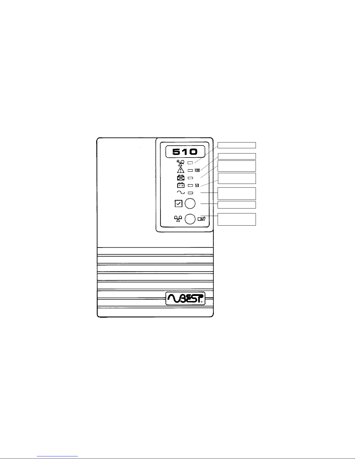
LOAD/SILENCE
SWITCH
TEST SWITCH
Fig 1 - BEST 510 Front Panel
Indicators and Switches
All Models
OVERLOAD LED
FAULT LED
Power On/AC
Present
BATTERY LOW/
WEAK LED
BATTERY MODE
LED
xii

BEST 510
DB-9 Port
System
ON/OFF
Switch
Input
Line Cord
Receptacle
Output
Receptacles
Circuit
Protector
Fig 2 - BEST 510 Rear Panel
600 VA Models
1
1
Output receptacles vary by model. See Specifications Page 24.
xiii

BEST 510
System
ON/OFF
Switch
Circuit
Protector
Input
Line Cord
Receptacle
Output
Receptacles
DB-9 Port
Fan
Fig 3 - BEST 510 Rear Panel
900 and 1250 VA Models
1
xiv
2
1
Output receptacles vary by model. See Specifications Page 24.
2
Note that Models 510-900U and 510-1250U have a fuse instead
of a circuit breaker.

BEST 510
Fans
Receptacle
Fuse
Input
Line
Cord
Receptacle or
Captive Input
Line Cord
(depending
on model)
DB-9 Port
Output
Receptacles
Circuit
Protector
Auxiliary
Battery
Connector
System
ON/OFF
Switch
Fig 4 - BEST 510 Rear Panel
1650 and 2000 VA Model
1
xv
1
Output receptacles vary by model. See Specifications Page 24.

BEST 510
DESCRIPTIONFEATURE
INTRODUCTION
1 Introduction
Congratulations on your purchase of a BEST 510 Uninterruptible Power
System (UPS)! We trust you will find it to be a valuable peripheral for
your electronic equipment. Please take just a few moments to read this
manual to obtain the maximum benefit from this product.
The BEST 510 UPS is an advanced sinewave UPS which is designed to
filter surges and sags that could potentially harm your equipment. It is
specifically engineered to protect a wide variety of systems, ranging from
computers and communication systems to industrial equipment. Under
normal AC utility power, the UPS filters out all small fluctuations. During
AC power failure, or if line voltage exceeds proper levels, the BEST 510
will automatically transfer to battery without any interruption to your
equipment. If the line voltage is low, it regulates incoming voltage to the
appropriate level without depleting the battery.
The UPS is equipped with many features which will make both your
equipment and UPS operation more reliable. See Table 1 below.
If the commercial line is frequently or
constantly low, the booster will lift the
output voltage to normal without draining
the internal battery.
Low input line booster
Automatic function and
battery test
This test is performed whenever the UPS is
turned on. It tests the function of the UPS
and the batteries status, thus preventing
unforeseen problems.
The DB-9 communication port provides a
signal to link with computers. Further
details are on pages 15-16 of this manual.
SNMP ready.
Computer communication
The UPS can operate in either a 50 or 60 Hz
environment. The UPS will automatically
select the correct frequency for your
environment.
The UPS will switch to backup mode and
provide power from its internal battery when
input line voltage is too high.
Input voltage
protection
50/60 Hz autosensing
TABLE 1

BEST 510
SIZING THE LOAD
Electrical equipment is often rated in VA (volt-amps). This represents the
rated voltage times the rated current.
Most electrical equipment usually has a manufacturer's label on the rear of
the equipment that indicates the voltage, frequency and current (amps) the
equipment requires for proper operation.
Find the current rating in amps for each piece of equipment to be
protected by the UPS. To determine the VA rating of each item to be
protected, multiply the amps for each item by the voltage your system is
running on. Now add up all the VA ratings. This sum is the VA rating
of the UPS necessary to protect your load. Round off to the next higher
VA rating if the UPS you are selecting is not available in exactly the VA
rating your equipment requires.
Most computers and their related components are rated at “worst case”,
with all of the expansion slots or bays fully loaded at low line voltage, so
your actual load is probably less.
Types of Loads
The BEST 510 UPS is designed to power all modern electronic equipment
(herein referred to as loads). The UPS output is specifically designed to
work with the switching power supplies found in microprocessor-based
equipment.
Sizing the Load 2

BEST 510
LASER PRINTERS AND YOUR UPS
BEST POWER does not recommend protecting laser printers with this
UPS. Laser printers will overload your UPS since they have a heating cycle
that causes adhesion of the toner to the paper. This heating cycle draws a
large amount of current. The BEST 510 UPS is not capable of supplying
this amount of current.
Most laser printers are not mission critical and can therefore be protected
with a power conditioner rather than a UPS. Just be sure that the power
conditioner you purchase can accommodate the high inrush currents of a
laser printer. If your printer is mission-critical and you want to protect it
with a UPS, the UPS must be sized to accommodate the high peak current
surge of the printer.
3 Laser Printers and Your UPS

BEST 510
1 — Unpack your UPS.
Although the packaging for your BEST 510 was designed specifically for
this unit and serves it well in protecting it from damage, you should
unpack the unit immediately and check for signs of concealed damage that
may have occurred in transit. Concealed damage is damage that may not be
apparent by the outside appearance of the packaging.
In case of damage, please notify the delivering carrier at once to examine
the goods, regardless of the external condition of the boxes. Under U.S.
Shipping Regulations, damage claims must be collected by the consignee.
Once your claim is established, damaged merchandise may be returned for
repair (see Page 26 for Return Policy). Do not return shipping-damaged
merchandise until after your claim has been established with the carrier.
Do not destroy packing material or boxes until the carrier's agent has
examined them. Save all packaging materials in case reshipment of
the UPS is required. Any damage sustained in transit when shipped
from the user, especially in an incorrect container, will not be covered
under warranty.
2 — Locate the UPS near the equipment to be
protected.
Your UPS should be in a controlled environment. A controlled
environment is one that is indoor, temperature-controlled and free of
conductive or semi-conductive contaminants. The BEST 510 is intended
for indoor use only. There should be adequate ventilation and the location
should be free of dust and fumes. Do not install the unit next to open
windows where uncontrolled environmental conditions could affect the
unit. Do not install the unit in any type of enclosure without first calling
BEST POWER Technical Support. The unit must have unrestricted air
flow. A 6” minimum clearance is required around the unit.
CAUTION
The environmental specifications shown in Table 2 on the next page
show the temperature and humidity limits of the UPS. Do not exceed
these limits.
INSTALLATION
Installation 4

BEST 510
3 — Connecting the UPS to AC power.
If your model UPS does not have a captive input line cord, attach the
receptacle end of the input line cord that came with your UPS to the
matching socket on the back panel of the UPS (See Figs. 2, 3 or 4,
depending on your model). Plug the UPS into a known live wall outlet
(receptacle).
WARNING
It is recommended that the UPS not be used with extension cords of
any kind. If it is absolutely necessary to use an extension cord, it is the
user’s responsibility to ensure that the extension cord is properly sized
and grounded to safely accommodate the load.
Use only the input cordset supplied with the UPS. Failure to do so can
result in a fire hazard.
ENVIRONMENTAL SPECIFICATIONS
Ambient Operating Temperature 0oC to 40oC (32oF to 104oF)
Ambient Storage Temperature -20oC to 50oC (-4oF to 122oF)
Humidity 0% to 95%, non condensing
Altitude 8,000 feet (2500M) maximum
INSTALLATION
(cont.)
5 Installation
TABLE 2

BEST 510
In order to obtain maximum backup time, the unit must remain on charge
for at least eight hours to recharge the internal battery. This is necessary
because the battery may have lost some charge in storage and transit.
The UPS will recharge its batteries automatically whenever input power is
provided to the UPS via the wall receptacle. There is no need to turn on
the System ON/OFF switch for recharging to occur
You may use the UPS immediately without recharging, but the backup
time may be less than specified. Go to Step 6 if you wish to use your
equipment immediately.
The System On/Off switch must be turned OFF if the UPS is not to be
used and is unplugged or the AC input power is shut off for extended
periods. Failure to do so will cause the battery to lose its charge and may
damage your battery.
INSTALLATION
(cont.)
4 — Recharge the batteries.
Installation 6
Note
If you are using the BEST 510 Auxiliary Battery Packs,
recharge time is considerably longer. Refer to Page 17
for specific recharge times by battery pack model.
Read the rest of this manual to thoroughly familiarize yourself with the
operation of your BEST 510.
5 — While you are waiting for the battery to
recharge, fill out and mail your warranty card
to BEST POWER.

BEST 510
6 — Connect and turn on your equipment to be
protected to the UPS.
Depending on your model UPS, there are two or more receptacles on the
back panel to plug in the equipment you want to protect. All models
containing an “A” in the model number are equipped with Australian
receptacles. Those models with an “E” in the model number are equipped
with an IEC receptacle, while those with a “U” OR “P” in the model
number are equipped with NEMA receptacles. Connect the power cord(s)
of your equipment to be protected to the output receptacles on the rear of
the UPS. Turn ON your equipment.
Turn ON the UPS by depressing the rear panel SYSTEM ON/OFF switch to
the position “ ” (ON). The UPS will beep and all LED lights will
illuminate, then the lights will extinguish one by one. Then the unit will
indicate how much load (in VA) the UPS is supporting via the load level
meter. See Page 12 for additional information on the load level meter
function..
After 4 seconds, the POWER ON and BATTERY MODE LEDs will
illuminate. The UPS is simulating a line failure by switching to its internal
batteries. This is a self-test function that ensures the UPS and batteries are
working properly. This test lasts for 4 seconds. After the self diagnostic
tests, the BATTERY MODE LED will go out.
To test the backup capability of the UPS during normal operation (AC line
present), depress the TEST switch on the front panel.
If the OVERLOAD LED is on, the UPS is overloaded. Unplug the least
critical devices from the UPS. If the FAULT LED is on, the battery or the
UPS may be abnormal. Please contact BEST POWER for assistance.
INSTALLATION
(cont.)
7 Installation
WARNING
The use of plug adaptors, outlet strips, or plug-in multiple outlet
panels is not recommended for use with your BEST UPS. If it is
absolutely necessary to use these items, it is the user's responsibility
to ensure that they are properly sized and grounded to safely
accommodate the load.

BEST 510
6 — Connect and turn on your equipment to be
protected to the UPS. (cont.)
INSTALLATION
(cont.)
Note
When powered ON via the rear panel System On/Off
switch, the BEST 510 will automatically select the correct
frequency (50 Hz or 60 Hz) for your site. There are no
DIP switches to set or other adjustments for you to make
in order to obtain the correct frequency.
7 — Earth Leakage
When installing this UPS, please ensure that the leakage currents of the
connected loads and the UPS, when added together, do not exceed a
maximum value shown below:
120V models 5.0mA maximum
240V models 3.5mA maximum
UPS Model UPS Leakage Maximum Allowable
Load Leakage
B510-600-U 1.40mA 3.60mA
B510-600-A, -E, -P 1.00mA 2.50mA
B510-900-U 1.80mA 3.20mA
B510-900-A, -E, -P 2.00mA 1.50mA
B510-1250-U 1.80mA 3.20mA
B510-1250-A, -E, -P 2.00mA 1.50mA
B510-1650-U 3.30mA 1.70mA
B510-1650-A, -E, -P 1.60mA 1.90mA
B510-2000-U 3.30mA 1.70mA
B510-2000-A, -E, -P 1.60mA 1.90mA
TABLE 3
If you do not know the load leakage current, or if you are unsure how to
measure the load leakage current, contact the manufacturer of the load.
Installation 8

BEST 510
INSTALLATION
(cont.)
8 — Connect your optional Auxiliary Battery
Packs.
BEST Auxiliary Battery Packs (Models 051-01BAT and 051-02BAT) are
designed to provide extra battery runtime to your 1650VA or 2000VA
BEST 510 UPS. They require no tools for installation.
Refer to BEST POWER’s Auxiliary Battery Pack Operation and
Installation Manual (Part Number 272-38116-0400-00) for Auxiliary
Battery Pack Installation instructions.
9 Installation
9 — If you are not using a UPS Monitoring
Software product, your UPS installation is
complete. If you are using a CheckUPS
Monitoring Software product supplied with this
UPS, plug your DB-9 connector into the DB-9 port
on the rear panel of the UPS (see Fig. 2, 3 or 4,
depending on your UPS model). Connect the
remaining end of the DB-9 cable to your
equipment, if it is not already connected to same.
Complete the monitoring product installation per
the instructions that came with the software.
The unit has a single DB-9 connector in the rear of the unit. UPS
control and monitoring signals can be sent to your host computer via this
connection. BEST Checkups is included n the UPS packaging and a suitable
DB9 cable is supplied.

BEST 510
INSTALLATION
(cont.)
Note 1. Relay rating + 24V 0.5A.
2. Pin 7 should be connected to ground only.
Note Failure to use the adaptor will result in the UPS
monitoring product not working properly.
10 — Installation of your UPS is now
complete.
Installation 10

BEST 510
WHEN A POWER FAILURE OCCURS
OPERATION
Upon return of AC power, the green “ON/AC Present” LED will
illuminate once again and the audible alarm will turn off. The green “ON/
AC Present” LED will remain illuminated if AC is present during a low
battery condition.
WHEN POWER RETURNS
When there are two minutes of backup time left (at the current load), the
audible alarm will beep once every second.
Upon loss of incoming AC power, your BEST 510 will operate from its
internal battery to provide your computer load with uninterrupted power.
The green front panel “ON/AC Present” LED will extinguish and the
audible alarm will beep every four seconds.
11 Operation

BEST 510
COMMUNICATIONS
Your BEST 510 UPS communicates critical system status information to
you via front panel LED lights, an audible alarm and a DB-9 port on the
rear panel.
OVERLOAD LED
This light comes on when the UPS is overloaded. This function works
whether the UPS in running on AC or battery power.
FAULT LED
This light turns on when the UPS is in a fault condition.
BATTERY LOW/WEAK LED
This light is either solid on or flashing. The light is solid on when the
batteries inside the UPS have less than 2 minutes backup time left. The
light is flashing when the batteries are weak. If the battery is weak, the
light will keep on flashing until you depress the test button again or when
batteries recover. It also flashes after an auto test done when the UPS is
installed or if the test button is pushed.
BATTERY MODE LED
This light is on when the UPS is providing power to your equipment from
its batteries.
TEST SWITCH
This switch is used to test if the UPS operation is normal. Pressing the
switch will force the UPS to switch to its internal battery. The UPS will
then automatically run a self-diagnostic test. This switch will work only
when incoming AC line is available.
LOAD TEST/ALARM SILENCE SWITCH
To perform a load test, depress the switch when incoming AC power is
available. The LEDs on the front panel become a bar graph indicating how
much load is on the UPS. See Page 13 for further information. When AC
power fails, this switch becomes an “alarm silence” function that will stop
the warning beeps when this switch is depressed.
AUDIBLE ALARM
If the incoming AC (mains) line fails and the unit is running on battery, the
audible alarm will beep every four seconds. If the internal battery is low,
or if there is an overload, the audible alarm will beep once every second. If
the battery is low, the audible alarm cannot be silenced without turning
OFF the System ON/OFF Switch on the rear of the unit. If the UPS is in a
fault condition, the audible alarm will sound continuously.
DB-9 PORT/CONTACT CLOSURES
A complete description of your BEST 510’s remote communication
capabilities is provided on pages 14 and 15 of this manual.
Communications 12

BEST 510
When you depress this switch, the lights on the front panel become a bar
graph showing how much of the UPS power is being used. The lights are
in 25% increments. For example, if three lights are on, it shows that the
equipment plugged into the UPS is drawing between 51% and 75% of the
UPS rated capacity. For a 600VA UPS with a computer load, this
represents between 300VA and 450VA.
Whenever you connect new equipment to the UPS, test the load level to
make sure the UPS does not become overloaded. If the UPS is
overloaded, the “OVERLOAD” light will turn on and the alarm will sound
continuously. The inverter backup function is automatically disabled until
the overload is removed.
COMMUNICATIONS
(cont.)
LOAD LEVEL METER
13 Communications
FIG. 5 BEST 510 LOAD LEVEL METER
25%
50%
100%
Overload
75%
Load Test/
Alarm
Silence
Switch

BEST 510
• Pins 2, 3 and 5 are all driven by open collector transistors. Pull up
resistors are required on the host computer side.
• Pin 2 is closed and Pin 3 is open when the utility is unavailable.
• When the battery backup time is less than 2 minutes, Pin 5 is
closed.
• In any condition, shorting Pin 8 with Pin 4 for 0.5 seconds will turn
off the UPS.
• Keeping Pin 6 in RS-232 high level (5-12V) for 0.5 seconds will
shut down the UPS. The UPS automatically “wakes up” when the
utility comes back. This shutdown function only operates in battery
mode.
• Pin 6 , Pin 7 and Pin 9 are for the RS-232 serial interface.
NOTE
1. Pins 2, 3 and 5: current rating +20Vdc, 50mA non-inductive.
2. Pin 4 should be connected to ground only.
COMMUNICATIONS
(cont.)
COMMUNICATION PORT
The UPS provides signals and RS-232 interface on a DB9 connector for the
host computer to contol the UPS and obtain the utility status.
The pin assignment for the female DB9 connector is:
Pin 1: NOT USED
Pin 2: LINE FAIL CONTACT (normally open)
Pin 3: LINE FAIL. (normally closed)
Pin 4: COMMON for Pins 2, 3, 5 and 8.
Pin 5: TWO MIN. CONTACT. (normally open)
Pin 6: RS-232 DATA TO UPS (RX)/
SHUTDOWN (high level)
Pin 7: RS-232 COMMON
Pin 8: REMOTE OFF (low level)
Pin 9: RS-232 DATA from UPS (TX).
Communications 14

BEST 510
COMMUNICATIONS
(cont.)
The DB-9 communication port also provides RS-232 software packages
with the following information:
• Charger status.
• Battery status and condition.
• Inverter status and condition.
• UPS status.
• Utility status.
• Energy Save. Utility power can be turned on and off at customer
pre-selected times to save power when the system is not in use.
You can control information exchange via your computer by typing a
query followed by <cr>. The UPS will respond with information followed
by a <cr> or action. UPS data will be provided at 2400 baud rate and
consist of 8 data bits, 1 stop bit and no parity bit. All the information is
provided in ASCII format.
HARDWARE:
BAUD RATE................................... : 2400bps
DATA LENGTH.............................. : 8 bits
STOP BIT...................................... : 1 bit
PARITY......................................... : None
CABLING:
COMPUTER UPS
RX <.............................. TX (pin 9)
TX ...............................> RX (pin 6)
GND ................................. GND (pin 7)
(9 pin female D-type connector)
Additional information is available in Appendix A of this manual.
15 Communications

BEST 510
INTERNAL BATTERY RUNTIMES
Model # VA Battery Ampere Hours Runtime *
Volts (Quantity) (in minutes)
Full Load/Half Load
B0510-0600 600 24VDC 6.5AH (2) 5/17
B0510-0900 900 48VDC 6.5AH (4) 8/25
B0510-1250 1250 48VDC 6.5AH (4) 5/18
B0510-1650 1650 48VDC 17AH (4) 12/46
B0510-2000 2000 48VDC 17AH (4) 8/29
BATTERY
Your BEST 510 comes equipped with an internal sealed, maintenance free
lead-acid battery. It is neither user-replaceable nor user-serviceable.
The BEST 510 UPS has been designed for quick, easy battery replacement
by a qualified service technician.
Listed below are the estimated run times for the BEST 510's internal
batteries, based on full load conditions.
Even the high-quality rechargeable batteries used by BEST POWER have a
limited lifetime. Battery life is impossible to predict accurately because
of the many variables involved (i.e. load, cycling and ambient
temperature). Experience has shown that batteries can be expected to last
three to five years under good conditions. Battery life can be reduced
by 50% or more by operating the unit at temperatures of 80oF (27oC)
or above. By operating and storing the unit in a proper environment (see
Environmental Specifications, Page 7), you can obtain maximum battery
life.
Batteries should be replaced when the backup time (with the same load) is
only 60% of what it was when the battery was nearly new (initial battery
runtimes actually improve after several complete discharge cycles).
BATTERY LIFE
Battery/Battery Life 16
* Battery runtime at 100% 0.70 pf.
TABLE 4
Recharge time: 8 hours maximum.
* Battery runtime at 0.70 pf.

BEST 510
OPTIONS
The following optional Auxiliary Battery Packs are available only for
1650 VA or 2000 VA BEST 510 UPS systems. They provide additional
battery backup time (under full load) as shown in Table 5 below.
NOTE :
A. only one 17AH Auxiliary Battery Pack can be attached to the
2000VA BEST 510 UPS
B. the 34 AH, Model 051-02BAT cannot be used with the
2000VA BEST 510 UPS UP
C. up to five 34AH Battery Packs can be used with 1650VA
“A”, “P” and “E” models. If using a combination of 17AH and
34 AH battery packs for “A”, “P” and “E” models, a maximum
total of 170AH is allowed. Exceeding 170 AH voids any
safety agency approvals on these units and can result in
damage to the UPS and/or Auxiliary Battery Packs.
D. the maximum Auxiliary Battery Pack AH allowed for all “U”
model BEST 510 UPS systems is 68AH.
Exceeding 68AH voids UL and CSA safety agency approvals
and can result in damage to the UPS and/or Auxiliary Battery
Packs.
17 Options
Model AH Width Depth Height Net Gross
(Ampere (mm/in) (mm/in) (mm/in) Weight Weight
Hours) (kg/lbs.) (kg/lbs.)
B510-01BAT 17AH 190/7.4 485/18.9 370/14.4 38/83.7 42/92.6
B510-02BAT 34AH 190/7.4 485/18.9 370/14.4 63/138.9 67/147.7
TABLE 5
Auxiliary Battery Pack Specifications

BEST 510
OPTIONS
(cont.)
Options 18
TABLE 6
Auxiliary Battery Pack Backup and Recharge Times
UPS Model Battery 85 102 119 136 153 170
Number Status AH AH AH AH AH AH
B510-1650 Backup 150 180 210 240 270 300
-A, -E, -P, -U Time min min min min min min
Recharge 44 51 59 67 75 83
Time hrs hrs hrs hrs hrs hrs
B510-2000 Backup N/A N/A N/A N/A N/A N/A
-A, -E, -P, -U Time
Recharge N/A N/A N/A N/A N/A N/A
Time
UPS Model Battery 17 34 51 68
Number Status AH AH AH AH
B510-1650 Backup 35 65 90 120
-A, -E, -P, -U Time min min min min
Recharge 13 19 27 35
Time hrs hrs hrs hrs
B510-2000 Backup 25 N/A N/A N/A
-A, -E, -P, -U Time min
Recharge 13 N/A N/A N/A
Time hrs

BEST 510
STORAGE
The UPS must be kept at reasonable temperatures to obtain maximum
battery life (15o to 21o C is ideal).
Your BEST 510 UPS requires little or no maintenance. Occasionally, the
input and output connections should be inspected for signs of damage and
repaired if necessary.
If you would like to clean the unit, first remove all power to the unit by
turning OFF the unit at the System On/Off switch and unplugging the
unit from the wall outlet.
If the unit is operating in an unusually dusty or dirty area, carefully
vacuum any dust from the input vents, as well as the chassis holes located
on the sides of the UPS and, depending on your model, any exhaust fans.
Note The unit MUST be recharged every 6 months to
recharge its internal batteries. The unit must be
recharged more frequently if it is stored above 35oC
(95oF) to obtain maximum battery life. This is
accomplished by simply plugging the unit into AC
power for 10 hours.
19 Storage/Maintenance
The warranty on this product will be affected if the unit is improperly
stored.
MAINTENANCE AND CLEANING
WARNING
Clean only the external surfaces of the unit. Use a cloth dampened
(not soaking) with water only. Allow the unit to completely dry before
returning the unit to service.

BEST 510
WARNING
Before replacing the fuse or opening the fuse holder, turn OFF the
UPS via the rear panel System On/Off Switch and unplug the UPS
from the wall receptacle.
Use a non-metallic tool to remove the twist lock fuse. Do not use pens,
pencils, paper clips, scissors, letter openers or similar items. Do NOT pry
fuses from their holders.
WARNING
When replacing fuses, replace only with fuses of the same type and
rating.
Turn off and unplug all of your equipment from the UPS.
Plug your UPS only into the wall receptacle and turn ON the rear panel
System On/Off Switch.
If the replacement fuse does not blow, then proceed with plugging in and
turning on your equipment one piece at a time.,
If the fuse blows after any given piece of equipment is plugged in and
turned on, then either the UPS is being overloaded for its VA rating or you
may have an internal short in your equipment.
Circuit Breaker
Some BEST 510 models are equipped with rear panel circuit breakers
instead of fuses. Depressing the circuit breaker turns the breaker on and
off.
FUSE REPLACEMENT
Fuses/Circuit Breakers 20

BEST 510
The Troubleshooting Chart on the next page covers most of the difficulties
that you may encounter under normal working conditions. If the UPS still
fails to operate properly after reviewing the chart, call BEST for service.
Telephone and facsimile numbers for BEST are shown on Page ?? and the
rear cover of this manual:
Please have the following information available when you call for service:
1. Model and Serial number.
2. Date problem first occurred.
3. Full description of problem.
TROUBLESHOOTING GUIDE
21 Troubleshooting

BEST 510
TROUBLESHOOTING GUIDE
(cont.)
Troubleshooting 22
TROUBLESHOOTING CHART
Problem Possible Cause Action to Take
UPS cannot turn on UPS rear panel main Turn on switch.
and there is no alarm. switch in off position.
Fuse open or circuit breaker Replace fuse
tripped. or reset breaker.
No incoming utility line Check input
or abnormal input power
frequency. and wall socket.
UPS cannot turn on Too low or high input Test input
and alarm sounds frequency. frequency.
continuously
Too low or high input Check input line
voltage. voltage.
“BATTERY MODE” No incoming line, very Check wall socket
light is on when incoming low or very high line and test input
line is thought to be line voltage.
normal.
Fuse open or circuit Replace fuse or
protector tripped. reset circuit
protector.
“FAULT” light is on and UPS failure. Call for service.
and alarm sounds
continuously.
Backup time is less Battery is not fully charged. Recharge the
than the rating. Possible internal battery battery for
charger failure. at least 6 hours.
Re-test the
backup time.
If problem
remains, call for
service.
“BATTERY MODE” and UPS is in battery mode Check input
“BATTERY LOW/WEAK” when input line fails. power and
lights are on and alarm Battery is near end of wall socket.
sounds periodically. discharge.
“OVERLOAD” light is on Overloaded. Remove the least
and alarm sounds critical load.
continuously.
“BATTERY LOW/WEAK” Weak battery. Recharge battery
is flashing. for 4 hours and
press the test
button again. If
the light keeps on
flashing, call for
service.
TABLE 7

BEST 510
SPECIFICATIONS
23 Specifications
Input
Voltage Range: 97V - 137V +2% THD <5% (“U” Models)
189V - 252V +2% THD <5% (“A” & “E” Models)
Frequency: 50/60 Hz, + 3Hz
Autosensing
Output
Waveform: Sinewave.
Line Mode
Regulation:
Battery Mode
Regulation: V
OUT
= V
NOM
+ 10%.
Battery Recharge
Time: 8 hours to rated runtime at VIN = V
NOM
.
Transfer Time: 4 ms typical.
Frequency:
Line Mode
or Boost Mode: Same as input frequency.
Battery Mode:50 Hz/60Hz, +0.1Hz, autosensing.
Model On AC Line Operation Booster Operation
1
Lower Limit Upper Limit To Booster Back to Line
120V Units 96 VAC 138 VAC <103 VAC >111 VAC
220V Units 172 VAC 264 VAC <192 VAC >212 VAC
230V Units 187 VAC 264 VAC <204 VAC >222 VAC
240V Units 192 VAC 268 VAC <206 VAC >222 VAC
1
For Booster operation, the booster will raise the output voltage to
normal without draining the internal batteries.

BEST 510
SPECIFICATIONS
(cont.)
Specifications 24
Environmental
Operating
Temperature: 0oC to 40oC (32oF to 104oF)
Storage
Temperature: -20oC to 50oC (-4oF to 122oF)
Humidity: 0% to 95%, non condensing
Altitude: 8,000 feet (2500M) maximum
Acoustic
Noise Level: <45dB (on battery back-up).
Communications
Status Controls and Indicators:
Front Panel: Test Switch/Alarm Silence Switch
LED Indicators:
Power ON/AC Present
Battery Mode
Battery low/weak (steady/flashing)
Fault
Overload
Load level in 25% increments.
Rear Panel: System ON/OFF Switch
Fuse or Circuit Breaker, depending on model.
DB-9 Connector:
RS-232/Contact Closure Interface
compatible with all major networks and
operating systems. Signals include:
AC utility fail
Low battery
Remote shutdown.
Audible Alarms: Line Loss: One beep every four seconds.
Battery Low: One beep every second.
UPS Fault: Continuous tone.
Overload: Continuous tone.
Safety Agency Approvals
“A”, “E” and “U” Models listed to UL 1778, CSA 22.2 No. 107 and
TUV EN50091-1 (1993.05).

BEST 510
SPECIFICATIONS
(cont.)
25 Specifications
VA Watts Model Number Nominal
Output
Voltage
Quantity and
Type Output
Receptacle
Input
Line
Cord
Runtime
Full/Half Load
Input
Protection
Rating
Dimensions
H x W x D
in. (mm)
Shipping
Weight
lbs (kg)
600 400 B510-600-U 120 4 NEMA 5-15 Note 1 5 min/17 min 8A fuse Note A 30.8/14
900 630 B510-900-U 120 6 NEMA 5-15 Note 1 8 min/25 min 15A fuse Note B 50.6/23
1250 900 B510-1250-U 120 6 NEMA 5-15 Note 1 5 min/18 min 15A fuse Note B 50.6/23
1650 1320 B510-1650-U 120 4 NEMA 5-15
+ 1 L5-20R
Note 2 12 min/46 min 30A circuit
breaker
Note C 123.3/56
2000 1600 B510-2000-U 120 4 NEMA 5-15
+ 1 LR-30R
Note 3 8 min/29 min 25A circuit
breaker
Note C 123.3/56
600 400 B510-600-E 230 4 IEC 320 Note 4 5 min/17 min 4A fuse Note A 30.8/14
900 630 B510-900-E 230 4 IEC 320 Note 4 8 min/25 min 10A circuit
breaker
Note B 50.6/23
1250 900 B510-1250-E 230 4 IEC 320 Note 4 5 min/18 min 10A circuit
breaker
Note B 50.6/23
1650 1320 B510-1650-E 230 4 IEC 320 Note 4 12 min/46 min 12A circuit
breaker
Note C 123.3/56
2000 1650 B510-2000-E 230 4 IEC 320 Note 4 8 min/29 min 12A circuit
breaker
Note C 123.3/56
600 400 B510-600-A 230 2 Australian Note 5 5 min/17 min 4A fuse Note A 30.8/14
900 630 B510-900-A 230 2 Australian Note 5 8 min/25 min 10A circuit
breaker
Note B 50.6/23
1250 900 B510-1250-A 230 2 Australian Note 5 5 min/18 min 10A circuit
breaker
Note B 50.6/23
1650 1320 B510-1650-A 230 3 Australian Note 5 12 min/46 min 12A circuit
breaker
Note C 123.3/56
2000 1600 B510-2000-A 230 3 Australian Note 5 8 min/29 min 12A circuit
breaker
Note C 123.3/56
600 400 B510-600-P 220 4 NEMA 5-15 Note 1 5 min/17 min 4A fuse Note A 30.8/14
900 630 B510-900-P 220 6 NEMA 5-15 Note 1 8 min/25 min 10A circuit
breaker
Note B 50.6/23
1250 900 B51-1250-P 220 6 NEMA 5-15 Note 1 5 min/18 min 10A circuit
breaker
Note B 50.6/23
1650 1320 B510-1650-P 220 4 NEMA 5-15
+ 1 L5-20R
Note 2 12 min/40 min 12A circuit
breaker
Note C 123.3/56
2000 1600 B510-2000-P 220 4 NEMA 5-15
+ 1 L5-30R
Note 3 8 min/29 min 12A circuit
breaker
Note C 123.3/56
Notes:
1. NEMA 5-15P A. 7.9 x 4.8 x 13.8 (200 x 122 x 350)
2. NEMA L5-20P B. 9.7 x 6.5 x 17.8 (246 x 165 x 453)
(equipped with captive line cord) C. 14.6 x 7.l5 x 19.1 (370 x 190 x 485)
3. NEMA L5-30P
(equipped with captive line cord)
4. 1 each Schuko and British.
5. Australian, 10A plug.

BEST 510
ADVANCED COMMUNICATIONS
COMMUNICATION PROTOCOL
STATUS ENQUIRY:
Computer: Q1<cr>
UPS: UPS status data stream, such as
(MMM.M NNN.N PPP.P QQQ RR.R S.SS TT.T b7b6b5b4b3b2b2b0<cr>
UPS status data stream:
(a) Start byte (
(b) Input Voltage: MMM.M
M is an integer number ranging from 0 to 9. The unit is volts.
(c) Input Fault Voltage: NNN.N
N is an integer number ranging from 0 to 9. Its purpose is to identify a
short duration voltage glitch that causes UPS to go to inverter mode. If this
occurs, input voltage will appear normal at query before glitch and will still
appear normal at next query.
The I/P fault voltage will hold the glitch voltage until next query. After the
query, the fault voltage will be same as voltage until next glitch occurs.
(d) Output Voltage: PPP.P
P is an integer number ranging from 0 to 9. The unit is volts.
(e) Output Current: QQQ
QQQ is an integer percent of maximum current, not an absolute value.
(f) Input Frequency: RR.R
R is an integer number ranging from 0 to 9. The unit is Hz.
(g) Battery Voltage: SS.S or S.SS
Actual battery voltage is provided in the form SS.S. The unit is volts.
(h) Temperature: TT.T
T is an integer number ranging from 0 to 9. The unit is degrees centigrade.
Appendix A 26

BEST 510
27 Appendix A
COMMUNICATION PROTOCOL
STATUS ENQUIRY (cont):
(i) UPS Status: b7b6b5b4b3b2b1b0
<bn> is an ACSII number “0” or “1”
UPS Status:
bn Description
7 1: Utility Fail (Immediate)
6 1: Battery Low
5 1: Bypass/Boost Active
4 1: UPS Failed
3 1: UPS type is Standby (() is on-line)
2 1: Test in Progress
1 1: Shutdown Active
0 Reserved (always 0)
(j) Stop Byte: <cr>
Example:
Computer: Q1<cr>
UPS: (208.4 140.0 208.4 034 59.9 2.05 35.0 00110000<cr>
means: Input voltage is 208.4V
Input fault voltage is 140.0V
Output voltage is 208.4V
Output current is 34%
Input frequency is 59.9 Hz
Battery voltage is 2.05V
Temperature is 35.0 degrees centigrade
UPS type is on-line, UPS failed, Bypass active and Shutdown
not active.
ADVANCED COMMUNICATIONS

BEST 510
Appendix A 28
ADVANCED COMMUNICATIONS
10 Second Test:
Computer: T<cr>
UPS: Test for 10 seconds and return to utility.
If battery low warning occurs during testing, the UPS will return
to AC utility immediately.
Test until Battery Low:
Computer: TL<cr>
UPS: Test until battery low and return to utility.
Test for Specified Time Period:
Computer: T<n><cr>
UPS: Test for <n> minutes
(a) During testing, UPS returns to utility immediately if
battery low occurs.
(b) <n> is a number ranging from 01 to 99.
Shutdown Command:
Computer: S<n><cr>
UPS: Shut UPS output off in <n> minutes
(a) The UPS output will shut off in <n> minutes, even if
the utility is present.
(b) The UPS may shutdown in less than <n> minutes due
to low battery.
(c) After UPS shutdown, the UPS controller monitors the
utility. If the utility is present, the UPS will wait for
10 seconds before restarting.
(d) <n> is a number ranging from 2., ..3., ..01, 02.., to 10.
For example S 3 <cr> = shut output off in (3) minutes

BEST 510
ADVANCED COMMUNICATIONS
29 Appendix A
Shutdown and Restore Command:
Computer: S<n>$<m><cr>
UPS: Shut UPS output off in <n> minutes, wait for
<m> minutes, then turn on UPS output.
(a) The shutdown sequence is the same as the previous
command. The UPS will restore either when <m>
expires or when the utility returns, whichever is
longer.
(b) If the UPS is in shutdown waiting status, the (‘’’
command cancels the shutdown command.
(c) If the UPS is in restore waiting status, the ‘’(‘’’
command cancels the shutdown command.
(d) <n> is a number ranging from 2., ..3., ..01, 02.., to 10.
(e) <m> is a number ranging from 0001 to 9999
Cancel Shutdown Command:
Computer: C<cr>
UPS: Cancel the SN<n><cr> and SN<n>R<m><cr>
command.
(a) If the UPS is in the shutdown waiting state, the
shutdown command is cancelled.
(b) If the UPS is in restore waiting state, the UPS output
is turned on , but the UPS will turn off for least 10
seconds (if utility is present).
Cancel Test Command:
Computer: CT<cr>
UPS: Cancel all test activity and connect the utility
to output immediately.

BEST 510
Appendix A 30
ADVANCED COMMUNICATIONS
Command Summary
Item Command Description
2 Q1 STATUS INQUIRY
3 T SECOND TEST
4 TL TEST UNTIL BATTERY
LOW
5 T<N> TEST FOR SPECIFIC TIME
PERIOD
6 S<N> SHUTDOWN COMMAND
7 S<N>R<M> SHUTDOWN AND
RESTORE COMMAND
8 C CANCEL SHUTDOWN
COMMAND
9 CT CANCEL TEST
COMMAND
TABLE 8

BEST 510
WARRANTY
31 Warranty
LIMITED WARRANTY (USA ONLY)
BEST POWER warrants this hardware product against defective material or
workmanship for a period of two years from the date of purchase by the end user.
Consumable and/or field replaceable items such as fuses and MOVs are not warranted.
BEST POWER will repair or replace the defective product at no charge to the buyer.
The warranty is void if BEST POWER determines that the product was subjected to
conditions outside the normal operating characteristics stated in the manual, or if there
had been shipping damage. This warranty does not cover repair or replacement because
of damage from unreasonable use (for example only, damage from road hazard, accident,
fire or other casualty, misuse, negligence, or incorrect wiring) and any use or installation
not in conformance with instructions furnished by BEST POWER, or repairs or
replacements needed because of modifications or parts not authorised or supplied by
BEST POWER. Any technical advice furnished before or after delivery in regards to the
use or application of BEST POWER products is furnished without charge and on the
basis that it represents BEST POWER's best judgement under the circumstances, but it
is used at the recipient's sole risk. BEST POWER shall in no event be liable for other
direct, special, incidental, indirect or penal charges.
Limitation of Remedies
Excepting injuries to persons or damage to physical property, BEST POWER's liability
(whether under the theories of breach of contract or warranty, negligence, or strict
liability) for product it manufactures and/or sells shall be limited to the purchase price of
such products.
Consequential Damages
In no event shall BEST POWER be liable for consequential damages arising out of or in
connection with this agreement. Including without limitation breach of any obligation
imposed on BEST POWER hereunder or in connection herewith.
There are no other warranties which extend beyond the description of the face thereof.
Repaired Products
Warranty on repaired products is for ninety days, on the repairs made, or the remainder
of the warranty, whichever is greater.
COUNTRIES OUTSIDE THE USA
Customers outside mainland USA should obtain a copy of the official warranty
statement applicable to their country. Contact your nearest BEST POWER Customer
Service Centre or BEST POWER Representative for a copy of this document.

BEST 510
Most instances of initial failure to operate properly can be remedied
through a telephone conversation between the user and BEST POWER.
Telephone and fax numbers for principal BEST POWER offices are on
the back cover of this manual.
If, during the course of your call, it is determined that a product must be
returned, your service representative will provide you with instructions.
All returns to BEST POWER must have a Return Material Authority
(RMA) Number. The following information is required to obtain an RMA
Number.
1. BEST part number.
2. Serial number.
3. Company name, address, phone number and contact
person.
4. Proof of purchase.
5. Special instructions, if any.
6. Description of problem.
Shipments must be made in the original packing container. Damage
resulting from shipment in a non-original container will void this
warranty.
For proper handling upon receipt at BEST POWER, the RMA Number
must be clearly placed in several locations on the outside of the package.
BEST POWER will not be responsible for damage to returned goods that
have not been properly packaged or damage exceeding normal wear and
tear.
Return Policy 32
RETURN POLICY

BEST 510
You have purchased a UPS that will provide you with many years of service, protecting your
equipment from surges, sags, and blackouts. This product incorporates the highest quality
standards in engineering, manufacturing and testing, and carries a 2 year warranty against defects
in material and workmanship. This product is backed by over 60 years of pride and integrity. We
are sure you will agree, there is no substitute for a BEST POWER.
Did you know that BEST POWER also makes:
— Single Phase UPS systems up to 18kVA
— Three Phase UPS systems to 350kVA
— Parallel Three Phase UPS Systems to 2MVA
— Plug in Power Conditioners to 3kVA
— Hardwired Single Phase Power Conditioners to 22.5kVA
— Constant Voltage Transformers to 7.5kVA
— AC/DC switching and linear Power Supplies
— CVDC Constant Voltage Ferroresonant Power Supplies
— Low Voltage General Purpose Transformers
— Industrial Control Transformers
BEST POWER products are available through an extensive distribution network. These
distributors offer literature, technical assistance, and a wide array of off-the-shelf
products for the fastest possible delivery.
In addition, BEST POWER field sales offices are conveniently located to provide prompt
attention to customer needs. Call BEST POWER direct to find the closest authorised
distributor.
Principal Facilities:
Phone Facsimile
North America
Best Power, Necedah (608) 565-7200 (608) 565-2221
Toll-Free (USA & Canada) 1-800-356-5794
Miami, Florida (305) 598-2328 (305) 598-3747
Canada (905) 564-7655 (905) 564-7657
Australia
SOLA Australia (61) 3-9706-5022 (61) 3-9794-9150
Europe
BEST POWER U.K. (44) 1962-844414 (44) 1962-841846
BEST POWER (France) (33) 76 85 56 30 (33) 76 53 86 26
BEST POWER (Germany) (49) 9131 -77700 (49) 9131-777050
BEST Borri Elettronica (Italy) (39) 2-6600661-2 (39) 2-6122481
BEST POWER AG (Switzerland) (41) 56-792860 (41) 56-281263
Mexico
BEST POWER (52) 5-399-0369 (52) 5-399-1320
Asia
BEST POWER Singapore (65) 293-8122 (65) 296-8766
BEST Asia Trading, Taiwan (886) 2-736-2933 (886) 2-733-4403
BEST POWER: The Power Experts
P/N 272-38116-0200-00
Rev. 02 02/96
 Loading...