

BESTEK NSP-2C62 User Manual
1
Network Security System
NSP-2C62
Always at the forefront of innovation
User Manual
2
This publication contains information that is protected by copyright. No part of it may be reproduced in any
form or by any means or used to make any transformation adaptation without the prior written permission
from the copyright holders.
This publication is provided for informational purposes only. The manufacturer makes no representations or
warranties with respect to the contents or use of this manual and specifically disclaims any express or implied
warranties of merchantability or fitness for any particular purpose. The user will assume the entire risk of the
use or the results of the use of this document. Further, the manufacturer reserves the right to revise this
publication and make changes to its contents at any time, without obligation to notify any person or entity of
such revisions or changes.
© 2011. All Rights Reserved.
All trademarks and registered trademarks of products appearing in this manual are the properties of their
respective holders.
This equipment has been tested and found to comply with the limits for a Class A digital device, pursuant to
Part 15 of the FCC rules. These limits are designed to provide reasonable protection against harmful interference
when the equipment is operated in a residential installation. This equipment generates, uses, and can radiate
radio frequency energy and, if not installed and used in accordance with the instruction manual, may cause
harmful interference to radio communications. However, there is no guarantee that interference will not occur
in a particular installation. If this equipment does cause harmful interference to radio or television reception,
which can be determined by turning the equipment off and on, the user is encouraged to try to correct the
interference by one or more of the following measures:
Reorient or relocate the receiving antenna.
Increase the separation between the equipment and the receiver.
Connect the equipment into an outlet on a circuit different from that to which the receiver is connected.
Consult the dealer or an experienced radio TV technician for help.
Notice:
1. The changes or modifications not expressly approved by the party responsible for compliance could void
the user’s authority to operate the equipment.
2. Shielded interface cables must be used in order to comply with the emission limits.
Copyright
Trademarks
FCC and DOC Statement on Class A
3
1. Warranty does not cover damages or failures that are raised from misuse of the product, inability to use the
product, unauthorized replacement or alteration of components and product specifications.
2. The warranty is void if the product has been subject to physical abuse, improper installation, modification,
accidents or unauthorized repair of the product.
3. Unless otherwise instructed in this user’s manual, the user may not, under any circumstances, attempt to
perform service, adjustments or repairs on the product, whether in or out of warranty. It must be returned
to the purchase point, factory or authorized service agency for all such work.
4. We will not be liable for any indirect, special, incidental or consequential damages to the product that has
been modified or altered.
It is quite easy to inadvertently damage your PC, system board, components or devices even before installing
them in your system unit. Static electrical discharge can damage computer components without causing any
signs of physical damage. You must take extra care in handling them to ensure against electrostatic build-up.
1. To prevent electrostatic build-up, leave the system board in its anti-static bag until you are ready to install
it.
2. Wear an antistatic wrist strap.
3. Do all preparation work on a static-free surface.
4. Hold the device only by its edges. Be careful not to touch any of the components, contacts or connections.
5. Avoid touching the pins or contacts on all modules and connectors. Hold modules or connectors by their
ends.
Important:
Electrostatic discharge (ESD) can damage your processor, disk drive and other
components. Perform the upgrade instruction procedures described at an ESD
workstation only. If such a station is not available, you can provide some ESD protection
by wearing an antistatic wrist strap and attaching it to a metal part of the system chassis.
If a wrist strap is unavailable, establish and maintain contact with the system chassis
throughout any procedures requiring ESD protection.
Warranty
Static Electricity Precautions
4
To avoid damage to the system:
• Use the correct AC input voltage range.
To reduce the risk of electric shock:
• Unplug the power cord before removing the system chassis cover for installation or servicing. After installation
or servicing, cover the system chassis before plugging the power cord.
Battery:
• Danger of explosion if battery incorrectly replaced.
• Replace only with the same or equivalent type recommend by the manufacturer.
• Dispose of used batteries according to local ordinance.
Before using the system, prepare basic system components.
If the system comes as a barebone; that is, none of the key components, including processor, memory, and hard
drive has been pre-installed as part of your purchase, you will need to at least ensure a compatible counterpart
is located and installed.
You will also need a few external system peripherals intended for the use of the system, a common pool with
at least a keyboard, a mouse, and a monitor is thus suggested.
Safety Measures
Before Using the
5
Table of Content
Copyright ................................................................................................................................................................ 2
Trademarks ............................................................................................................................................................. 2
FCC and DOC Statement On Class A ....................................................................................................................... 2
Warranty ................................................................................................................................................................. 3
Static Electricity Precautions .................................................................................................................................. 3
Safety Measures ..................................................................................................................................................... 4
Before Using the System Board .............................................................................................................................. 4
Table of Content ..................................................................................................................................................... 5
Chapter 1 General Information
1.1 Main Feature .................................................................................................................................................... 7
1.2 Specifications .................................................................................................................................................... 8
1.3 System Layout ................................................................................................................................................... 9
1.4 Indicators and Features .................................................................................................................................. 10
Chapter 2 Preparation
2.1 Before You Begin ............................................................................................................................................. 12
2.2 Precautions ..................................................................................................................................................... 12
2.3 Open Up Top Cover ......................................................................................................................................... 13
2.4 Accessing Processor ........................................................................................................................................ 14
2.5 Accessing Memory .......................................................................................................................................... 15
2.6 Adding 2.5”/3.5” SATA Hard Drive .................................................................................................................. 16
2.7 Accessing Expansion Card ............................................................................................................................... 18
Chapter 3 Operation
3.1 Turning On The System ................................................................................................................................... 20
3.2 Installing Operating System & Drivers ............................................................................................................ 22
Chapter 4 BIOS Setup
4.1 Entering Setup ................................................................................................................................................ 25
4.2 Getting Help .................................................................................................................................................... 25
4.3 Control Keys .................................................................................................................................................... 25
4.4 The Main Menu ............................................................................................................................................... 26
4.5 The Advanced Menu ........................................................................................................................................ 28
4.6 The Chipset Menu ..................................................................................................................................................... 50
4.7 The Security Menu .......................................................................................................................................... 62
4.8 The Server Management Menu ....................................................................................................................... 67
4.9 The Boot Menu ............................................................................................................................................... 71
4.10 The Save & Exit Menu ................................................................................................................................... 75
Chapter 5 Q&A ................................................................................................................... 76
6
Chapter 1
General Information
7
Processor Performance
NSP-2C62 is a 2U Rack Mount Network Security System that, pre-installed with BNX-C602 security board,
featuring on Intel® C602 PCH, supporting dual Intel® Xeon® LGA2011 E5-2600 V2 processors, of 22nm Ivy
Bridge architecture, with maximum up to 12 processor cores and 30MB Smart Cache. Niche of such a new
combination allows more direct writing data of a portion of processor cache to HDD or SSD, bypassing the
memory.
Introduction of Dual-Channel DDR3 Memory
The eight Quad-Channel DDR3 DIMM slots are designed to carry up to 64GB UDIMM (Unregistered DIMM)
and 256GB RDIMM (Registered DIMM) of frequency 1066/1333/1600MHz with ECC support, delivering a
large bandwidth performance boost to memory intensive applications by lower module voltage down to
1.35V.
Onboard Four Gigabit LAN Ports
The four Intel® 82574L Gigabit LAN Ports are ideal for almost any contemporary software development with
outstanding compatibility, where no extra network driver or hotfix is required to boost up the availability
and performance.
Expansion
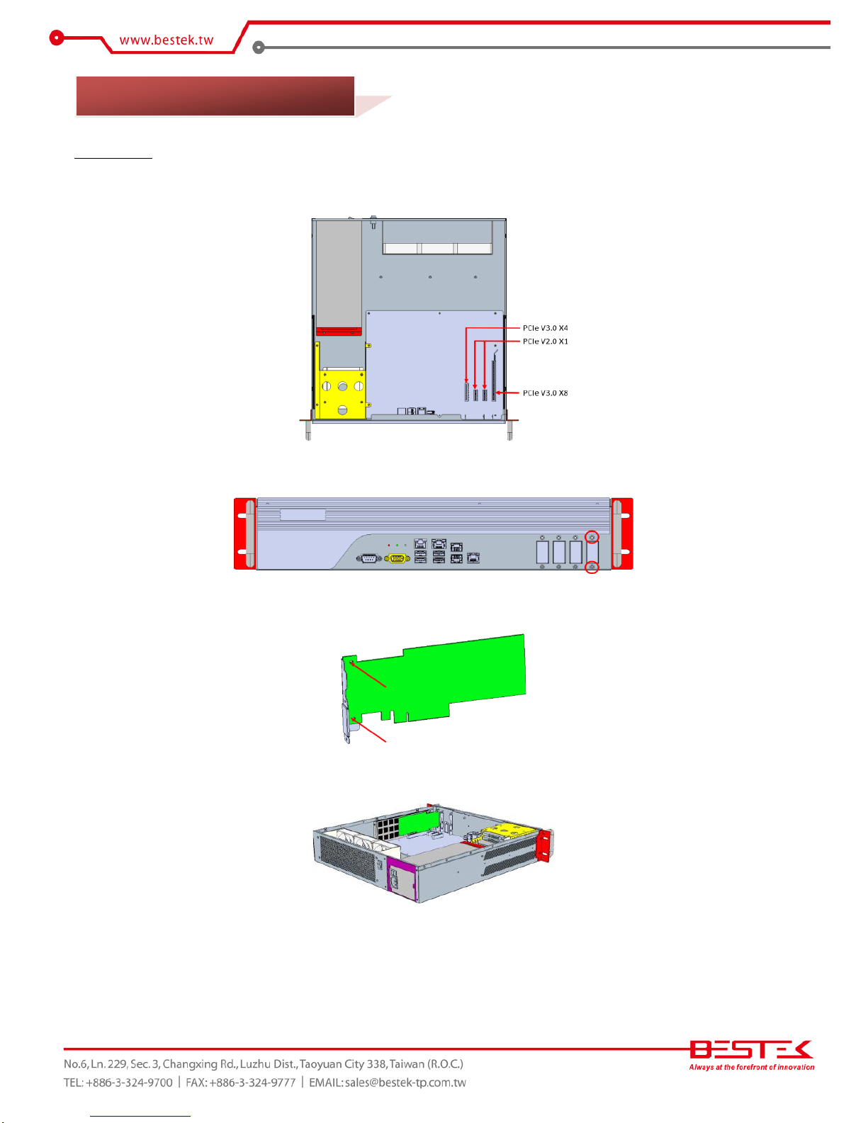
The four PCIe expansion slots offer the capability of adding standard 2U low-profile cards, for the purpose
of such as RAID, Network, encryption, or acceleration. Those available are two PCIe V2.0 X1 slots, one PCIe
V3.0 X4 slot, and one PCIe V3.0 X8 slot.
List of Key Features
Intel® C602 Chipset
Dual Intel® Xeon® LGA2011 E5-2600 V2 Processor
Eight Quad-Channel DDR3 ECC DIMM Slots up to 64GB UDIMM or 256GB RDIMM
Two 2.5” + Two 3.5” Internal Drive Bays
Two USB 2.0 + Two USB 3.0 Ports at front
One RJ45 Mgmt Port
Four Intel® 82574L RJ45 Gigabit LAN Ports
Two PCIe V2.0 X1 Slots
One PCIe V3.0 X4 Slot
One PCIe V3.0 X8 Slot
Two CPU Cooler Fans + Three 80mm Rear Fans
2U 1+1 420W Redundant Power Supply
2U Rack Mount of 430mm Depth
1.1 Main Feature
8
Core Engine
Chipset
Intel® C602 PCH
Processor
Support Dual Intel® E5-2600 v2 Processor
Memory
8x DDR3 1066/1333/1600MHz ECC/Non-ECC DIMM, 4 Channel
Up to 64GB UDIMM Memory or 256GB RDIMM
Display
AST2300
Ethernet
Controller
4x Onboard Intel® 82574L GbE Controllers
1x 10/100 Management Port
Storage
SATA
2x 2.5” + 2x 3.5” SATA/SAS Internal HDD Drive Bays.
Support RAID Function by C602 PCH (SATA only) or PCIe RAID Card (SATA/SAS).
SATADOM
Supported
Front I/O
COM
1x DB9 RS-232
VGA
1x DB15
USB
2x USB 2.0 + 2x USB 3.0
LAN
4x RJ45 1G LAN
IPMI
1x RJ45 IPMI Port
Indication
1x Power LED, 1x HDD LED
Rear I/O
Switch
1x Rock Type Power Switch
Power Inlet
2x
Expansion
PCIe
1x PCIe X8 Slot
1x PCIe X4 Slot
2x PCIe X1 Slots
Power
Type
420W + 420W Redundant Power Supply, 100-240Vac, 47-63Hz
Cooling
CPU Fan
2x 60mm CPU Cooler Fans
System Fan
3x 80mm System Fans at rear side
Other
H/W Monitoring
Monitor temperature, voltage, and fan speed, auto-throttling control at CPU overheat
Environment
Operating Temp.
0oC ~ 40oC
Storage Temp.
-20oC ~ 70oC
Humidity
10% ~ 90% (Non-Condensing)
Mechanical
Dimension
435mm (W) x 450mm (D) x 88mm (H)
1.2 Specifications

9
Figure 1.1: System Layout of NSP-2C62
1.3 System Layout
10
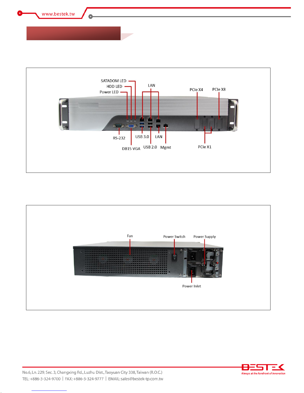
►
Front View
►
Rear View
1.4 Indicators & Features
11
Chapter 2
Preparation
12
A stable and clean working environment are essential. Dust and dirt can get into components and cause a
malfunction. Use containers to keep small components separated.
Adequate lighting and proper tools can prevent you from accidentally damaging the internal components. Most
of the procedures that follow require only a few simple tools, including the following:
A Philips screwdriver
A flat-tipped screwdriver
A set of jewelers Screwdrivers
A grounding strap
An anti-static pad
Using your fingers can disconnect most of the connections. It is recommended that you do not use needle-nosed
pliers to disconnect connections as these can damage the soft metal or plastic parts of the connectors.
Before working on internal components, make sure that the power is off. Ground yourself before touching any
internal components, by touching a metal object. Static electricity can damage many of the electronic
components. Humid environment tend to have less static electricity than dry
environments.
A grounding strap is
warranted whenever danger of static electricity exists.
Computer components and electronic circuit boards can be damaged by discharges of static electricity. Working
on the computers that are still connected to a power supply can be extremely dangerous. Follow the guidelines
below to avoid damage to your computer or yourself:
Always disconnect the unit from the power outlet whenever you are working inside the case.
If possible, wear a grounded wrist strap when you are working inside the computer case. Alternatively,
discharge any static electricity by touching the bare metal chassis of the unit case, or the bare
metal body
of any other grounded appliance.
Hold electronic circuit boards by the edges only. Never touch the components on the board unless it is
necessary to do so. Do not flex or stress the circuit board.
Leave all components inside the static-proof packaging that they shipped with until they are ready for
installation.
Use correct screws and do not over tighten screws.
2.1 Before You Begin
13
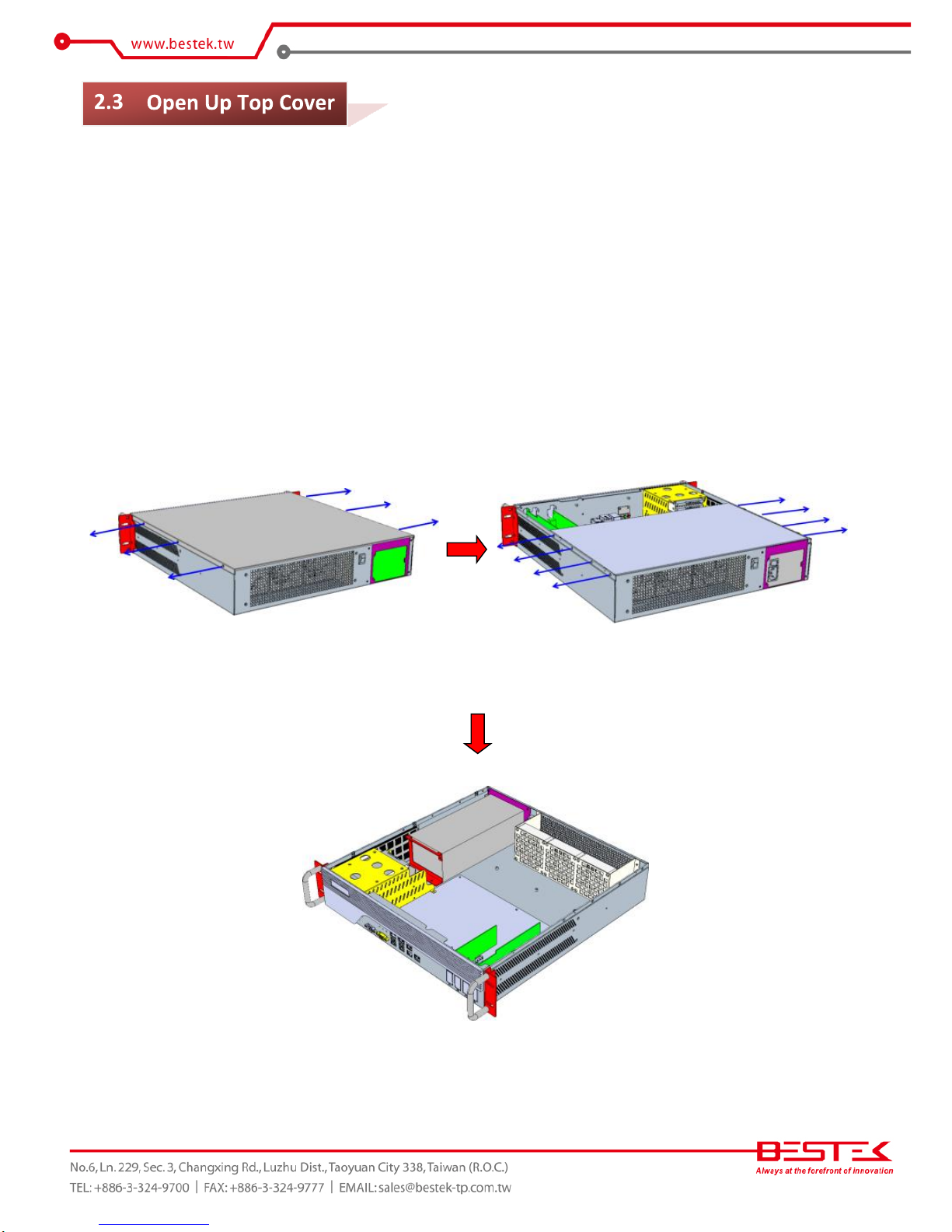
This is the first step of all to proceed with, if you are to install (or change) a processor (hard drive or memory
module).
Please remove the 6 screws on the two sides as indicated in the places below, prior to any moving of the top
cover. It is recommended to push the top cover backwards so as to detach the cover tongue out of the snatchup at front side, before the lift-up or removal of the top cover.
Also remove 8 screws to detach the internal Fan docking plate.
Securing the screws is essential for they would be re-used for the restoration of the top cover, after all
preparation procedures are completed.
14
The built-in BNX-C602 server board supports only LGA2011 E5-2600 V2 processor. Below is a list of some
compatible processors:
Code
Core
Speed
Cache
Thermal
E5-2603 V2
4
1.8GHz
10MB
80W
E5-2609 V2
4
2.5GHz
10MB
80W
E5-2620 V2
6
2.1GHz
15MB
80W
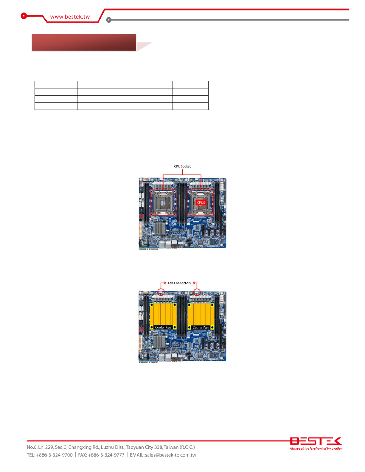
Procedures:
(1) To install processor into LGA2011 socket, please find the CPU socket on BNX-C602 server board (as indicated
below):
(1) Add CPU onto the socket. If there is only one CPU to be installed, please install on CPU0.
(2) Add some acceptable amount of thermal paste onto CPU.
(3) Find the CPU heat sink in the accessory pack, add it onto processor surface. Make sure the cooler fan is on the
motherboard I/O side and fascinate the four screws on it.
(4) Please add the power connector of CPU Cooler fan onto motherboard FAN.
2.4 Accessing Processor
15
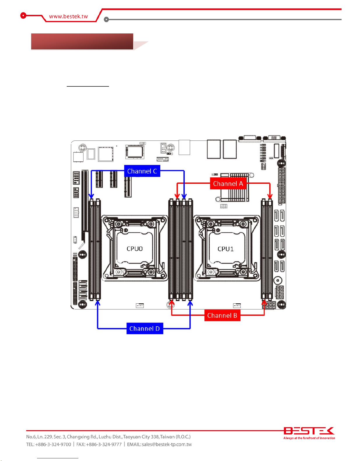
The built-in BNX-C602 server board supports eight DDR3 ECC memory module, enabling dual/quad-channel
architecture. This however requires a specific placement of some appropriate number of memory modules
(ideally, at least two are needed for dual-channel, and four for quad-channel). The memory modules are
installed into matching banks, as a way to be placed in separate channels, allowing the memory controller
access to each memory module at the same time, as a consequence of bandwidth increase accordingly and
proportionally. Once placed in the correct banks, dual-channel/quad-channel feature would be automatically
enabled, with no need of extra software deployment or firmware optimization. It is not required that identical
modules be used in these separate banks, but this is usually recommended for best dual/-channel or quadchannel operation.
(2) If CPU1 is not installed, all the memory controlled by CPU1 will not be present in the system.
(3) Always add memory in pairs by channel.
(4) Avoid adding odd number of memory modules.
(5) If two memory modules are installed on any channel, memory runs on single channel mode.
(6) If four memory modules are installed on any two channels, memory runs on dual channel
mode.
(7) If six memory modules are installed on any three channels, memory runs on triple channel
mode.
(8) If eight memory modules are installed on all slots, memory runs on quad channel mode.
2.5 Accessing Memory

16
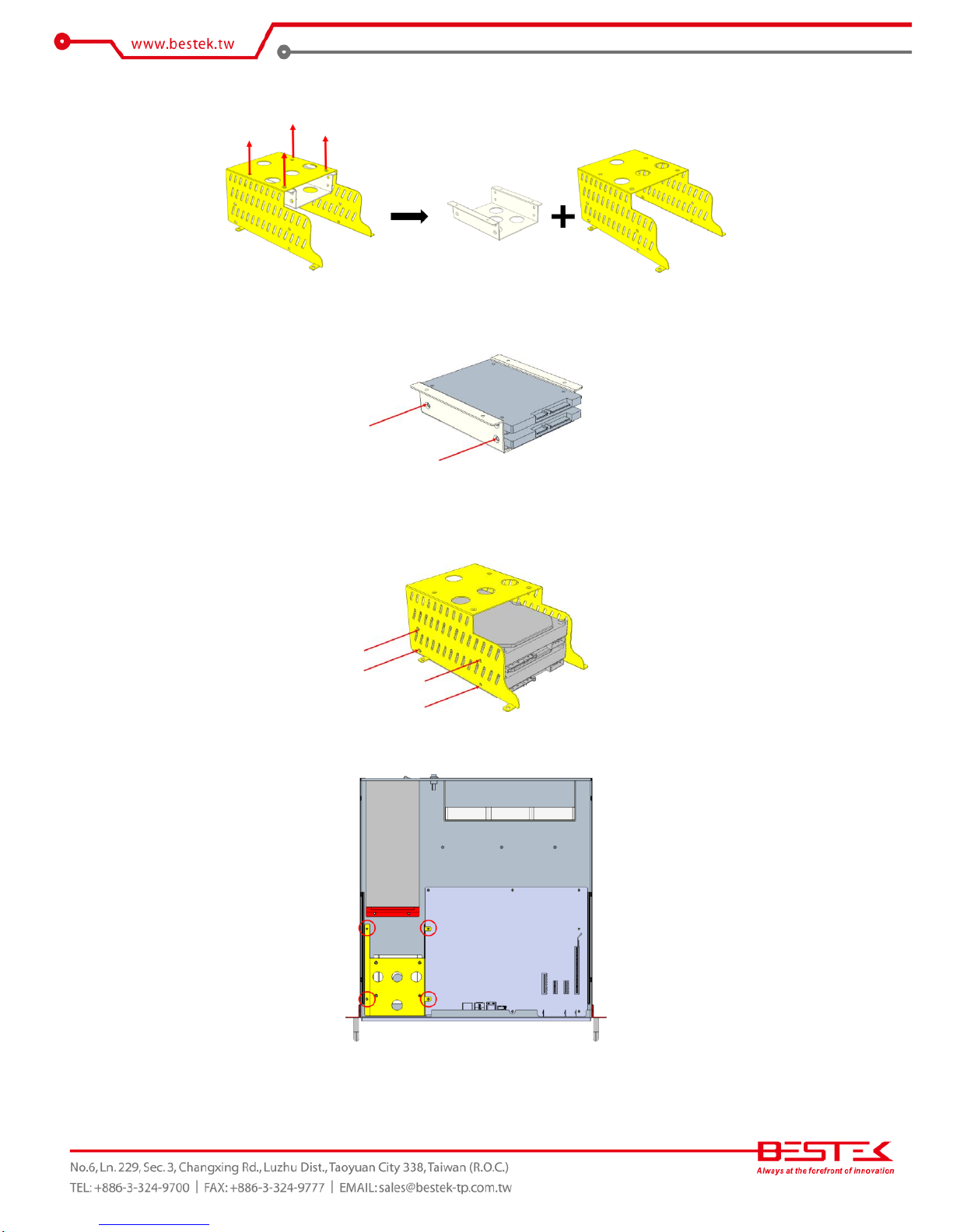
Procedures:
(1) Turn off the system and open up the top cover.
(2) Locate the drive bay brackets.
(3) Remove the four screws at the red circles to detach the drive bay bracket.
2.6 Adding 2.5”/3.5” SATA Hard Drive
17
(4) Remove the four screws on the top of drive bay bracket to disassembly the hard drive bracket.
(5) To add a 2.5” hard drive, integrate 2.5” hard drive into the 2.5” hard drive bracket and add four screws to
secure it. This bracket is designed to hold up to two 2.5” hard drives.
(6) To add a 3.5” hard drive, integrate 3.5” hard drive into the 3.5” hard drive bracket and add four screws to
secure it. This bracket is designed to hold up to two 3.5” hard drives.
(7) Restore this Hard Drive subset back to the chassis and add the four screws back to position.
(8) Add SATA signal cable and SATA power cable on all installed Hard Drives to complete the work.
18
Procedures:
(1) Turn off the system and open up the top cover.
(2) Select one of the slots as below where a card is to be added, for instance, PCIe V3.0 X8 slot.
(3) Remove the front 2 bracket screws to acquire the bracket.
(4) Attach the PCIe card onto this bracket and add two screws to complete the assembly.
(5) Put the subset back into the system on the target slot, and add the two screws back at the front side.
2.7 Adding Expansion Card
19
Chapter 3
Operation
20
Please add VGA cable on VGA port, and USB keyboard/mouse onto the USB ports, at the front side.
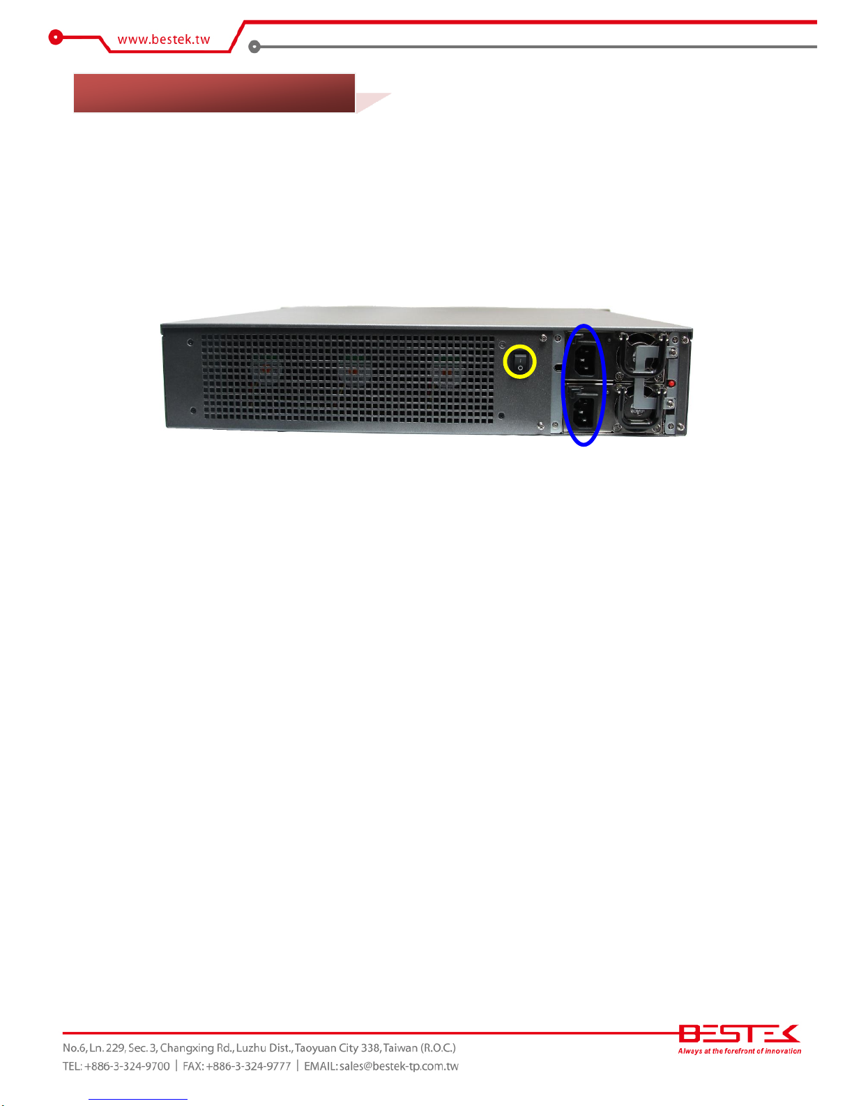
Watch Input AC Power Range
Please leave the AC power cord as the last cable to be added, right on the AC Inlet as indicated below with
blue circle. The AC input range of the built-in Power Supply is 100-240Vac. If your AC input is not within this
range, though rarely possible in fact, it is not compliant with the system and you should not plug in the AC
power cord.
System Is Up On AC Power
In some cases, depending on whether a BIOS setting has been configured to allow immediate power-on upon
the delivery of AC power, system might come right up unexpectedly for no particular reason. Please refer to
BIOS section for details with “Restore On AC Power Loss”. Should you wish to bring it down, simply press once
on the power switch (located next to power supply with yellow circle), or press and hold for 4 seconds, to
reach that goal. However, in most occasions, without such abrupt event as stated above, simply press once on
the Power Switch to turn on the system.
Power Redundancy
In some cases, NSP-2C62 would come with one 2U redundant power that has two independent power
modules, with each of them capable of sustaining the entire system operation alone.
The standard redundancy of this power supply would trigger the internal audible alarm in the light of various
incidences onto one of the modules, such as:
(1) No AC input at the power inlet
(2) Power module not at the correct plugged-in operation position
(3) Module malfunction.
In these cases, please press on the “red button” to disable the alarm signal first, followed by the attempts
below respectively:
(1) Making sure that AC power cord is firmly added
(2) Power module is pushed gently into the position again
(3) The malfunctioned module has been swapped with a working replacement.
3.1 Turning On The System
21
Power LED
The power LED (PWR) can be found at front panel (left of the three) and shall come lit constant ON at system
start.
Hard Drive LED
The hard drive LED (HDD) can be found at front panel (middle of the three) and shall blink in the wake of any
SAS hard drive activity.
System LED
This system LED (SYS) represents the SATADOM activity. This LED blink in accordance to all SATADOM
read/write incidences.
First screen & Optimal BIOS Setting
Once the system successfully boots up, it shall activate display signal on monitor, disclosing some system
information as checkpoints for debugging, thereafter users are encouraged to bring up BIOS setup menu to at
least load the optimal BIOS setting, as the first thing to do at power on. Please refer to the BIOS section for
substantial details.

22
Confirm the Hard Drive List
The system is designed to allow booting from a variety of internal devices, including USB pen drive, SATA
drive, and SAS drive, etc. Given the tiny footprint and slow performance of USB pen drive, SAS/SATA drive and
SATADOM are more likely the targets to carry operating system and can be found in the detected drive list, in
the section of SATA/SAS Configuration.
In the event that a particular SATA/SAS/SATADOM device is not detected and prompted in the device list,
hardly would the system boot from any of them. Please turn off the system, check or re-apply the SATA cable
and SATA power cable to ensure an appropriate connection.
In case the system comes with a RAID card onto which your SAS/SATA drives are attached, these hard drives
will not be detected by Intel® C602 PCH and certainly not present in the system BIOS drive list. Instead, the
drive detection job is completed at RAID controller. Please manage to find them in the configuration menu of
the RAID controller.
Always Mind the SATA Mode
SATA controller is embedded in the Intel® C602 chipset, and shall run only in one single SATA mode at a time.
Three different modes are available: IDE, AHCI, and RAID. Please ensure that a SATA mode has been selected
for the installation, and always use this particular mode to boot the operating system installed on that SATA
mode. Failed to boot the operating system with the correct SATA mode would very probably run into system
collapse. While thus disaster occurs, please re-select a SATA mode to try again the advisability of such change,
so as to recollect the mode being used at the installation phase.
Procedures to load operating system:
(1) Please attach USB CD-ROM or DVD-ROM drive.
(2) Start or restart the system.
(3) Press “del” to go to BIOS setup menu.
(4) Choose to confirm SATA Controller status. If it is enabled, select a SATA mode and go to (6).
(5) If SATA Controller is disabled, bring it up and reboot to allow a re-detection of Hard Drives.
(6) Confirm if the Hard Drive has been detected by the prompt of it on the drive list.
(7) Scroll and choose to boot from optical device (CD-ROM or DVD-ROM).
(8) Save and reboot the system to activate the change and start the installation.
(9) Upon reception of messages or instruction from Operating System CD or DVD, please proceed with the rest of
the work as installer instructs.
Loading Extra Driver Files
Some challenges might occur during the installation, as if the issue of no Hard Drive detected, where extra
driver files are needed. This is mostly found, when AHCI or RAID mode is selected if attached to onboard
SATA/SAS ports, or an extra RAID card is deployed to manage hard drives. Please follow the instruction from
operating system to load proper driver files to complete the installation.
On completion of the installation of operating system such as Microsoft Windows, please find the driver CD in
the enclosed accessory bag and proceed with driver files installation in the sequence as: INF (Chipset), VGA,
and LAN. If some driver updates are available by Windows Update, please accept the updates when prompted.
3.2 Installing Operating System & Drivers
23
Chapter 4
BIOS Setup
24
About the BIOS
The BIOS (Basic Input and Output System) Setup program is a menu driven utility that enables you to make
changes to the system configuration and tailor your system to suit your individual work needs. It is a ROMbased configuration utility that displays the system’s configuration status and provides you with a tool to set
system parameters. These parameters are stored in non-volatile battery-backed-up CMOS RAM that saves this
information even when the power is turned off. When the system is turned back on, the system is configured
with the values stored in CMOS.
With easy-to-use pull down menus, you can configure such items as:
Hard drives, diskette drives, and peripherals
Video display type and display options
Password protection from unauthorized use
Power management features
When to Run BIOS
This program should be executed under the following conditions:
When changing the system configurations.
When a configuration error is detected by the system and you are prompted to make changes to the
Setup program.
When resetting the system clock
.
When setting the CPU clock speed so that it automatically runs either fast or slow.
When redefining the communication ports to prevent any conflicts.
When making changes to the Power Management configuration.
When changing the password or making other changes to the security setup
.
Normally, CMOS setup is needed when the system hardware is not consistent with the information contained
in the CMOS RAM, whenever the CMOS RAM loses power, or when the system features need to be changed.
When to Update BIOS
In the event that new features are released and a BIOS update is required, you will need to update your BIOS on
your own, with the help of an appropriate guide, a reference tool, and some command files for the job.
Please seek for help from your local dealer, or send your request to our technical support department.
 Loading...