

BESTEK FEB-1251 User Manual
1
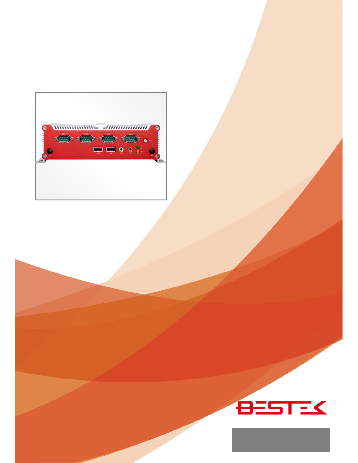
Fanless System
FEB-1251
Always at the forefront of innovation
User Manual
2
This publication contains information that is protected by copyright. No part of it may be reproduced in any
form or by any means or used to make any transformation adaptation without the prior written permission
from the copyright holders.
This publication is provided for informational purposes only. The manufacturer makes no representations or
warranties with respect to the contents or use of this manual and specifically disclaims any express or implied
warranties of merchantability or fitness for any particular purpose. The user will assume the entire risk of the
use or the results of the use of this document. Further, the manufacturer reserves the right to revise this
publication and make changes to its contents at any time, without obligation to notify any person or entity of
such revisions or changes.
© 2011. All Rights Reserved.
All trademarks and registered trademarks of products appearing in this manual are the properties of their
respective holders.
This equipment has been tested and found to comply with the limits for a Class A digital device, pursuant to
Part 15 of the FCC rules. These limits are designed to provide reasonable protection against harmful interference
when the equipment is operated in a residential installation. This equipment generates, uses, and can radiate
radio frequency energy and, if not installed and used in accordance with the instruction manual, may cause
harmful interference to radio communications. However, there is no guarantee that interference will not occur
in a particular installation. If this equipment does cause harmful interference to radio or television reception,
which can be determined by turning the equipment off and on, the user is encouraged to try to correct the
interference by one or more of the following measures:
Reorient or relocate the receiving antenna.
Increase the separation between the equipment and the receiver.
Connect the equipment into an outlet on a circuit different from that to which the receiver is connected.
Consult the dealer or an experienced radio TV technician for help.
Notice:
1. The changes or modifications not expressly approved by the party responsible for compliance could void
the user’s authority to operate the equipment.
2. Shielded interface cables must be used in order to comply with the emission limits.
Copyright
Trademarks
FCC and DOC Statement on Class A
3
1. Warranty does not cover damages or failures that are raised from misuse of the product, inability to use the
product, unauthorized replacement or alteration of components and product specifications.
2. The warranty is void if the product has been subject to physical abuse, improper installation, modification,
accidents or unauthorized repair of the product.
3. Unless otherwise instructed in this user’s manual, the user may not, under any circumstances, attempt to
perform service, adjustments or repairs on the product, whether in or out of warranty. It must be returned
to the purchase point, factory or authorized service agency for all such work.
4. We will not be liable for any indirect, special, incidental or consequential damages to the product that has
been modified or altered.
It is quite easy to inadvertently damage your PC, system board, components or devices even before installing
them in your system unit. Static electrical discharge can damage computer components without causing any
signs of physical damage. You must take extra care in handling them to ensure against electrostatic build-up.
1. To prevent electrostatic build-up, leave the system board in its anti-static bag until you are ready to install
it.
2. Wear an antistatic wrist strap.
3. Do all preparation work on a static-free surface.
4. Hold the device only by its edges. Be careful not to touch any of the components, contacts or connections.
5. Avoid touching the pins or contacts on all modules and connectors. Hold modules or connectors by their
ends.
Important:
Electrostatic discharge (ESD) can damage your processor, disk drive and other
components. Perform the upgrade instruction procedures described at an ESD
workstation only. If such a station is not available, you can provide some ESD protection
by wearing an antistatic wrist strap and attaching it to a metal part of the system chassis.
If a wrist strap is unavailable, establish and maintain contact with the system chassis
throughout any procedures requiring ESD protection.
Warranty
Static Electricity Precautions
4
To avoid damage to the system:
• Use the correct AC input voltage range.
To reduce the risk of electric shock:
• Unplug the power cord before removing the system chassis cover for installation or servicing. After installation
or servicing, cover the system chassis before plugging the power cord.
Battery:
• Danger of explosion if battery incorrectly replaced.
• Replace only with the same or equivalent type recommend by the manufacturer.
• Dispose of used batteries according to local ordinance.
Before using the system, prepare basic system components.
If the system comes as a barebone; that is, none of the key components, including processor, memory, and hard
drive has been pre-installed as part of your purchase, you will need to at least ensure a compatible counterpart
is located and installed.
You will also need a few external system peripherals intended for the use of the system, a common pool with
at least a keyboard, a mouse, and a monitor is thus suggested.
Safety Measures
Before Using the
5
Table of Content
Copyright ....................................................................................................................................................................
2
Trademarks .................................................................................................................................................................... 2
FCC and DOC Statement On Class A .............................................................................................................................. 2
Warranty ........................................................................................................................................................................ 3
Static Electricity Precautions ......................................................................................................................................... 3
Safety Measures ............................................................................................................................................................ 4
Before Using the System Board ..................................................................................................................................... 4
Table of Content ............................................................................................................................................................ 5
Chapter 1 General Information
1.1 Main
Feature ........................................................................................................................................................... 7
1.2
Specifications .......................................................................................................................................................
8
1.3 System Layout ................................................................................................................................................... 9
1.4 Indicators and Features .................................................................................................................................. 10
Chapter 2 Preparation
2.1 Before You Begin ...................................................................................................................................... 13
2.2
Precautions .........................................................................................................................................................
13
2.3 Open Up Bottom Cover
......................................................................................................................................
14
2.4 Accessing Memory ............................................................................................................................................. 15
2.5 Accessing 2.5” Drive ......................................................................................................................................... 16
2.6 Accessing CFast Card ...................................................................................................................................... 17
2.7 Installing Wireless Module & Antenna ........................................................................................................... 18
2.8 Accessing SIM Card ......................................................................................................................................... 20
2.9 Installing SATADOM ........................................................................................................................................ 21
Chapter 3 Operation
3.1 Turning On The System .................................................................................................................................... 23
3.2 Installing
Operating System & Drivers ........................................................................................................
24
3.3 Understanding LED Indicators ........................................................................................................................ 25
Chapter 4 BIOS Setup
4.1 Entering Setup ................................................................................................................................................ 28
4.2 Getting Help .................................................................................................................................................... 28
4.3 Control Keys .................................................................................................................................................... 28
4.4 The Main Menu ............................................................................................................................................... 29
4.5 The Advanced Menu ........................................................................................................................................ 30
4.6 The Chipset Menu ..................................................................................................................................................... 32
4.7 The Boot Menu ................................................................................................................................................ 34
4.8 The Security Menu .......................................................................................................................................... 35
4.9 The Save & Exit Menu ...................................................................................................................................... 36
Chapter 5 Auxiliary Information
5.1 GPIO Programming Guide .............................................................................................................................. 39
5.2 WDT Programming Guide ............................................................................................................................... 40
6
Chapter 1
General Information
7
Processor Performance
FEB-1251 is a fanless embedded wall mount system that is pre-installed with Intel® Cedarview D2550 DualCore 1.86GHz processor bundled with integrated graphic and one SO-DIMM slot supporting up to maximum
4GB DDR3-800/1066.
All-In-One & Compact Design
The system boasts a considerably compact size of just 185x131x54mm, with one DVI-I, one HDMI, dual
gigabit RJ45 network, four COM ports, six USB 2.0, and one CFast, all available on the built-in embedded
board therein the TCO (Total Cost of Ownership) can be minimized. The provision of wide range DC power
input and the true fanless feature has made the system a perfect controller for FA and MA, where a variety
of different power sources, such as 12/19/24Vdc, are available.
List of Key Features
Onboard Intel® Atom™ D2550
1x HDMI + 1x DVI-I Output
Dual Intel® Gigabit LAN Ports
2x RS-232, 2x RS-232/422/485
6x USB 2.0 Ports
1x External CFast Socket
1x miniPCIe Slot
Two Antenna Outlets
10~28Vdc Wide Range Power Input
1.1 Main Feature
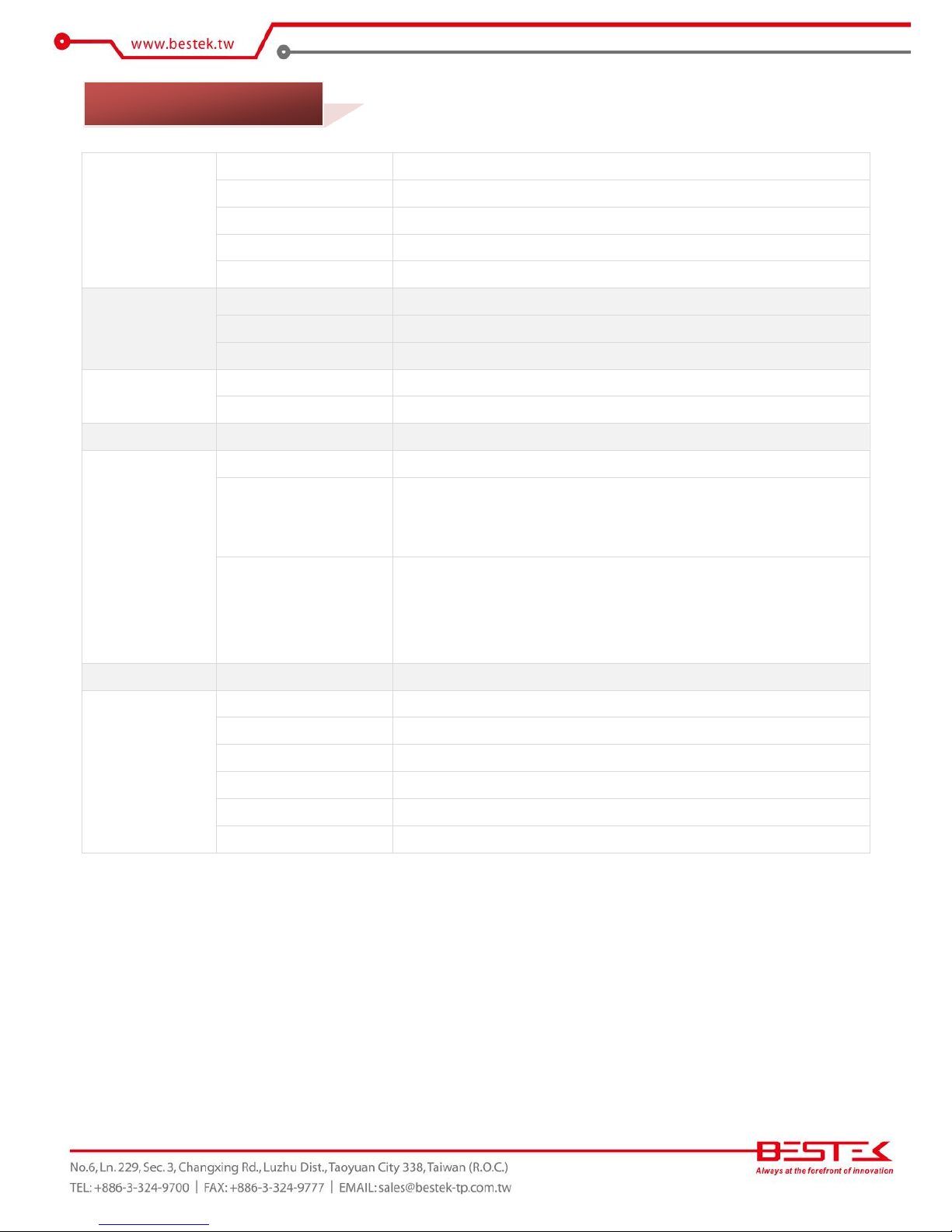
8
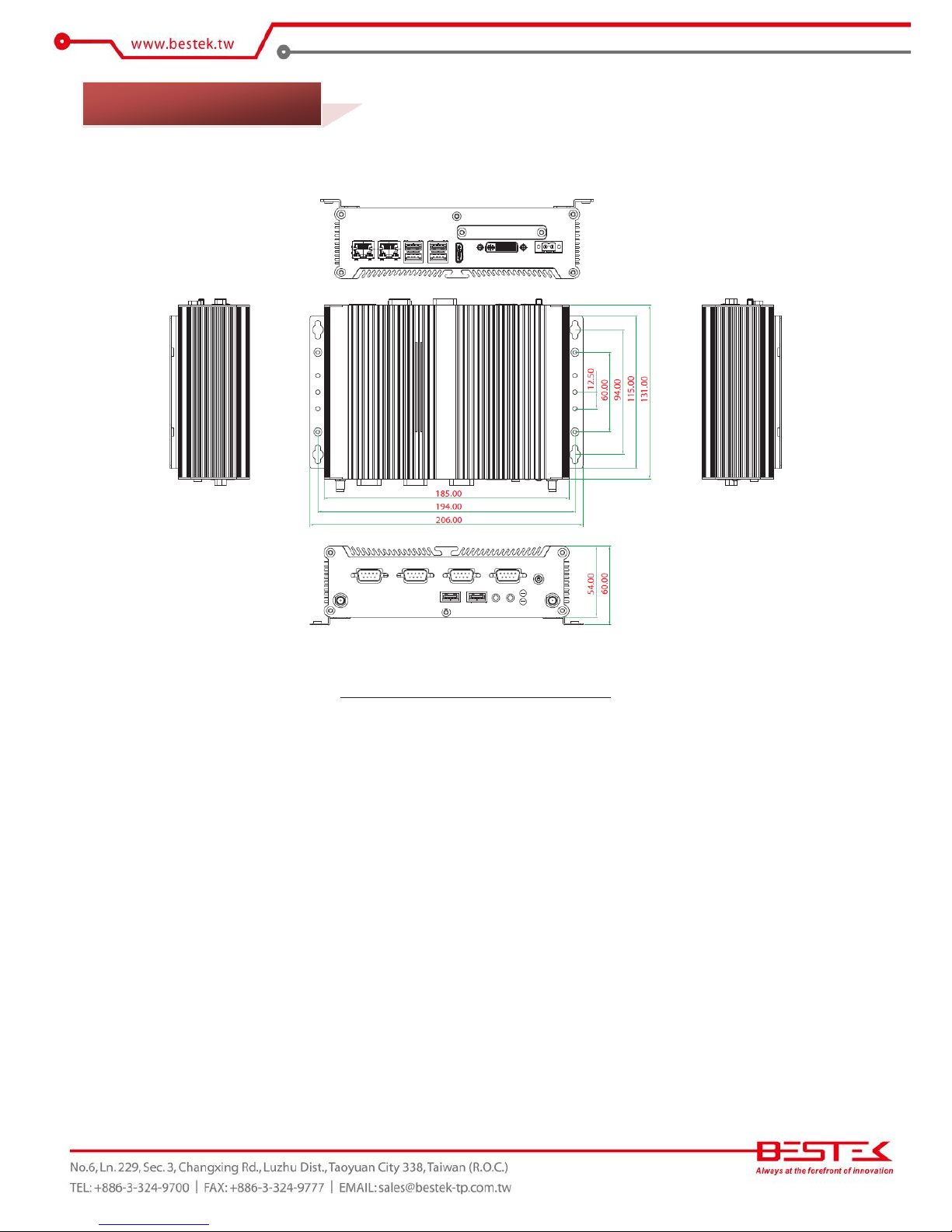
Construction
Form Factor
Proprietary Wall Mount Chassis
Material
Aluminum
Dimension (W x D x H)
185 (W) x 131 (D) x 54 (H) mm
Color
Silver & Red
Certification
CE/FCC
System
Processor
Intel® Atom™ Cedarview D2550 Dual-Core Processor
Memory
1x DDR3 SO-DIMM Slot up to 4GB
Power
12~28Vdc / Optional 12Vdc Power Adaptor
Drive Bays
SATA HDD
1 (2.5”)
CFast
1x External Accessible
Cooling
True Fanless Design via Aluminum Housing
Connectivity
Communication
Dual Intel® 82574L PCIe GbE, Support WOL & PXE
Front I/O
1x ATX Power Switch, 1x Power LED, 1x HDD LED
4 x COM Ports (Two RS232/422/485)
2x USB 2.0 Ports, 2x Audio Jacks, 2x Antenna Outlets
Rear I/O
2x RJ45 LAN Ports, 4 x USB 2.0 Ports
1x HDMI + 1x DVI-I (Support VGA via Cable)
1x 2-pin Power Input, Support +10~28Vdc
1x External Screwed Type CFast Socket
Expansion Slots
Rear Access
1x miniPCIe Slots for Half-sized and Full-sized Adaptor
Environment
Operating Temperature
-5 ~ 55oC
Storage Temperature
-20 ~ 80oC
Operating Humidity
0% ~ 90%
Storage Humidity
0% ~ 90%
Shock Protection
HDD (20G), CFast (50G)
Vibration Protection
Random (0.5Grms), Sinusoidal (0.5Grms)
1.2 Specifications
9
Figure 1.1: System Layout of FEB-1251
1.3 System Layout
10
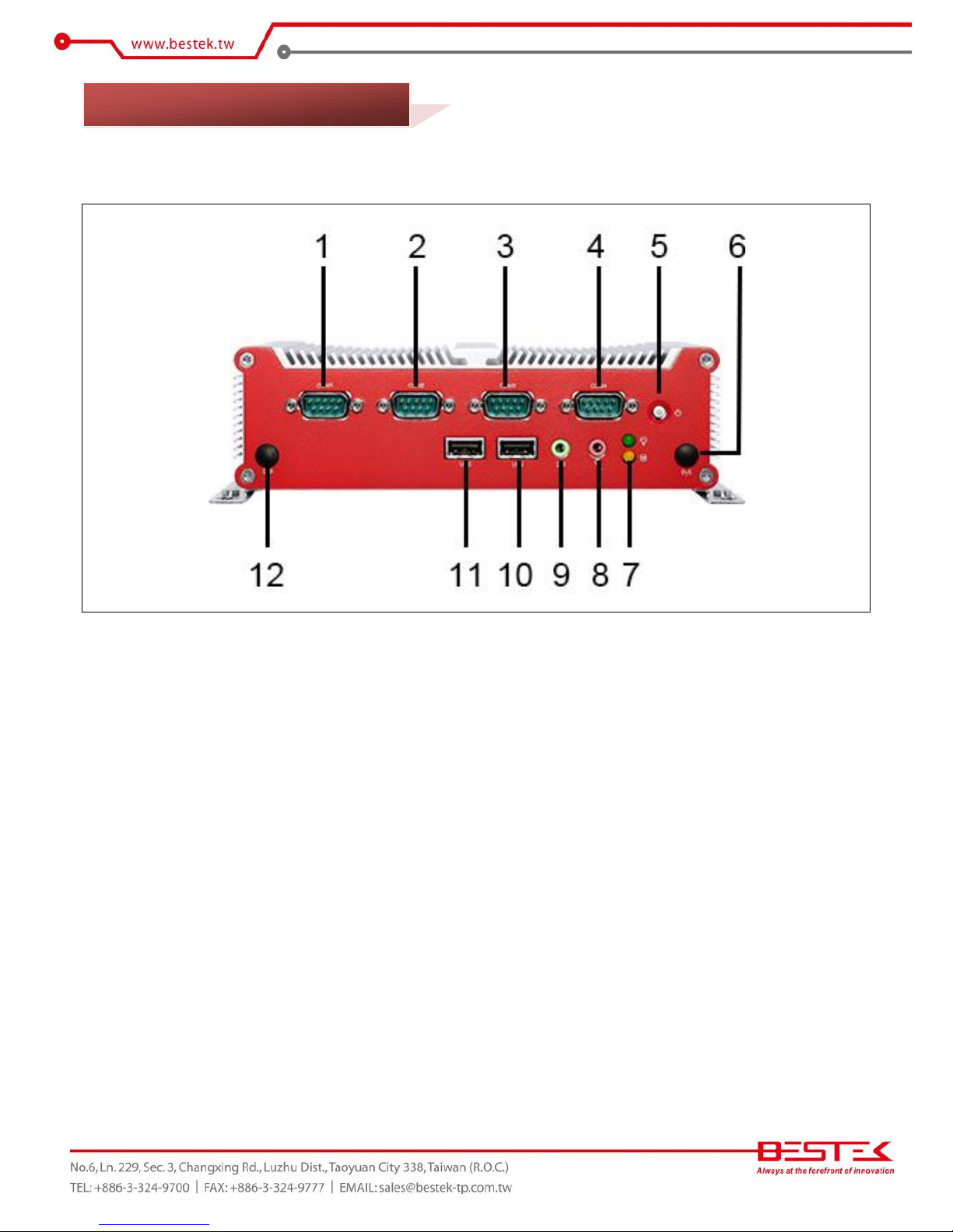
►
Front View
1. DB9 RS-232
2. DB9 RS-232/422/485
3. DB9 RS-232/422/485
4. DB9 RS-232
5. Power Switch
6. Antenna Cut-Out
7. Power LED (Green) + HDD LED (Yellow)
8. Microphone Jack
9. Line-Out Jack
10. 1* USB 2.0
11. 1* USB 2.0
12. Antenna Cut-Out
1.4 Indicators & Features
11
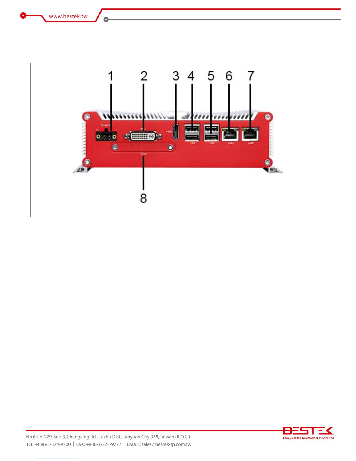
►
Rear View
1. 10-28Vdc Power Input
2. DVI-I
3. HDMI
4. 2* USB 2.0
5. 2* USB 2.0
6. LAN1
7. LAN2
8. CFast Socket
12
Chapter 2
Preparation
13
A stable and clean working environment are essential. Dust and dirt can get into components and cause a
malfunction. Use containers to keep small components separated.
Adequate lighting and proper tools can prevent you from accidentally damaging the internal components. Most
of the procedures that follow require only a few simple tools, including the following:
A Philips screwdriver
A flat-tipped screwdriver
A set of jewelers Screwdrivers
A grounding strap
An anti-static pad
Using your fingers can disconnect most of the connections. It is recommended that you do not use needle-nosed
pliers to disconnect connections as these can damage the soft metal or plastic parts of the connectors.
Before working on internal components, make sure that the power is off. Ground yourself before touching any
internal components, by touching a metal object. Static electricity can damage many of the electronic
components. Humid environment tend to have less static electricity than dry
environments.
A grounding strap is
warranted whenever danger of static electricity exists.
Computer components and electronic circuit boards can be damaged by discharges of static electricity. Working
on the computers that are still connected to a power supply can be extremely dangerous. Follow the guidelines
below to avoid damage to your computer or yourself:
Always disconnect the unit from the power outlet whenever you are working inside the case.
If possible, wear a grounded wrist strap when you are working inside the computer case. Alternatively,
discharge any static electricity by touching the bare metal chassis of the unit case, or the bare
metal body
of any other grounded appliance.
Hold electronic circuit boards by the edges only. Never touch the components on the board unless it is
necessary to do so. Do not flex or stress the circuit board.
Leave all components inside the static-proof packaging that they shipped with until they are ready for
installation.
Use correct screws and do not over tighten screws.
2.1 Before You Begin
 Loading...