

BESTEK BNX-H81 User Manual

1
Security Board
BNX-H81
Always at the forefront of innovation
User Manual
2
This publication contains information that is protected by copyright. No part of it may be reproduced in any
form or by any means or used to make any transformation adaptation without the prior written permission
from the copyright holders.
This publication is provided for informational purposes only. The manufacturer makes no representations or
warranties with respect to the contents or use of this manual and specifically disclaims any express or implied
warranties of merchantability or fitness for any particular purpose. The user will assume the entire risk of the
use or the results of the use of this document. Further, the manufacturer reserves the right to revise this
publication and make changes to its contents at any time, without obligation to notify any person or entity of
such revisions or changes.
© 2011. All Rights Reserved.
All trademarks and registered trademarks of products appearing in this manual are the properties of their
respective holders.
This equipment has been tested and found to comply with the limits for a Class A digital device, pursuant to
Part 15 of the FCC rules. These limits are designed to provide reasonable protection against harmful interference
when the equipment is operated in a residential installation. This equipment generates, uses, and can radiate
radio frequency energy and, if not installed and used in accordance with the instruction manual, may cause
harmful interference to radio communications. However, there is no guarantee that interference will not occur
in a particular installation. If this equipment does cause harmful interference to radio or television reception,
which can be determined by turning the equipment off and on, the user is encouraged to try to correct the
interference by one or more of the following measures:
Reorient or relocate the receiving antenna.
Increase the separation between the equipment and the receiver.
Connect the equipment into an outlet on a circuit different from that to which the receiver is connected.
Consult the dealer or an experienced radio TV technician for help.
Notice:
1. The changes or modifications not expressly approved by the party responsible for compliance could void
the user’s authority to operate the equipment.
2. Shielded interface cables must be used in order to comply with the emission limits.
Copyright
Trademarks
FCC and DOC Statement on Class A
3
1. Warranty does not cover damages or failures that are raised from misuse of the product, inability to use the
product, unauthorized replacement or alteration of components and product specifications.
2. The warranty is void if the product has been subject to physical abuse, improper installation, modification,
accidents or unauthorized repair of the product.
3. Unless otherwise instructed in this user’s manual, the user may not, under any circumstances, attempt to
perform service, adjustments or repairs on the product, whether in or out of warranty. It must be returned
to the purchase point, factory or authorized service agency for all such work.
4. We will not be liable for any indirect, special, incidental or consequential damages to the product that has
been modified or altered.
It is quite easy to inadvertently damage your PC, system board, components or devices even before installing
them in your system unit. Static electrical discharge can damage computer components without causing any
signs of physical damage. You must take extra care in handling them to ensure against electrostatic build-up.
1. To prevent electrostatic build-up, leave the system board in its anti-static bag until you are ready to install
it.
2. Wear an antistatic wrist strap.
3. Do all preparation work on a static-free surface.
4. Hold the device only by its edges. Be careful not to touch any of the components, contacts or connections.
5. Avoid touching the pins or contacts on all modules and connectors. Hold modules or connectors by their
ends.
Important:
Electrostatic discharge (ESD) can damage your processor, disk drive and other
components. Perform the upgrade instruction procedures described at an ESD
workstation only. If such a station is not available, you can provide some ESD protection
by wearing an antistatic wrist strap and attaching it to a metal part of the system chassis.
If a wrist strap is unavailable, establish and maintain contact with the system chassis
throughout any procedures requiring ESD protection.
Warranty
Static Electricity Precautions
4
To avoid damage to the system:
• Use the correct AC input voltage range.
To reduce the risk of electric shock:
• Unplug the power cord before removing the system chassis cover for installation or servicing. After installation
or servicing, cover the system chassis before plugging the power cord.
Battery:
• Danger of explosion if battery incorrectly replaced.
• Replace only with the same or equivalent type recommend by the manufacturer.
• Dispose of used batteries according to local ordinance.
Before using the system, prepare basic system components.
If the system comes as a barebone; that is, none of the key components, including processor, memory, and hard
drive has been pre-installed as part of your purchase, you will need to at least ensure a compatible counterpart
is located and installed.
You will also need a few external system peripherals intended for the use of the system, a common pool with
at least a keyboard, a mouse, and a monitor is thus suggested.
Safety Measures
Before Using the System

5
Table of Content
Copyright ....................................................................................................................................................................
2
Trademarks .................................................................................................................................................................... 2
FCC and DOC Statement On Class A .............................................................................................................................. 2
Warranty ........................................................................................................................................................................ 3
Static Electricity Precautions ......................................................................................................................................... 3
Safety Measures ............................................................................................................................................................ 4
Before Using the System Board ..................................................................................................................................... 4
Table of Content ............................................................................................................................................................ 5
Chapter 1 General Information
1.1 Main
Feature ........................................................................................................................................................... 8
1.2
Specifications .......................................................................................................................................................
9
1.3 Optional LAN Modules ............................................................................................................................................. 10
1.4 Board Layout ................................................................................................................................................... 11
Chapter 2 Jumper Setting
2.1 Before You Begin ..................................................................................................................................... 13
2.2
Precautions .........................................................................................................................................................
13
2.3 Setting
Jumpers ..................................................................................................................................................
14
2.4 Edge Connectors ................................................................................................................................................ 15
2.5 Location of Jumpers and Connectors ............................................................................................................. 16
2.6 Jumpers ........................................................................................................................................................... 18
2.7 Internal Connectors ........................................................................................................................................ 19
Chapter 3 Operation
3.1 System Memory .............................................................................................................................................. 22
3.2 Installing
Memory ......................................................................................................................................
22
3.3 Installing LGA1150 Intel® Core-i CPU, Heat Sink, and Fan ............................................................................... 24
3.4 Adding Power Connectors .............................................................................................................................. 27
3.5 Adding CompactFlash Cards ........................................................................................................................... 28
Chapter 4 BIOS Setup
4.1 Entering Setup ................................................................................................................................................ 31
4.2 Getting Help .................................................................................................................................................... 31
4.3 Control Keys .................................................................................................................................................... 31
4.4 The Main Menu ............................................................................................................................................... 32
4.5 The Advanced Menu ........................................................................................................................................ 33
4.6 The Chipset Menu ..................................................................................................................................................... 37
4.7 The Boot Menu ................................................................................................................................................ 38
4.8 The Security Menu .......................................................................................................................................... 39
4.9 The Save & Exit Menu ...................................................................................................................................... 40

6
Chapter 5 Programming Guide
5.1 Watchdog Timer ............................................................................................................................................. 42
5.2 Programmable LED ......................................................................................................................................... 47
5.3 LAN Bypass ..................................................................................................................................................... 49
5.4 Programmable Switch ...................................................................................................................................... 52

7
Chapter 1
General Information

8
Network Security Board
BNX-H81 is a Network Security Board, featuring on Intel® H81 chipset, supports Intel® Gen-4 LGA1150 Xeon
E3-1200 V3 and Celeron®, Pentium®, Core®-i3/i5/i7 processors that carry the built-in Intel® HD Graphic
engine. Below is a brief list of available processors as a quick reference:
Celeron® Processor: G1820/G1820TE
Pentium® Processor: G3420/G3320TE
Core®-i3 Processor: i3-4330/i3-4330TE
Core®-i5 Processor: i5-4570S/i5-4570TE
Core®-i7 Processor: i7-4770S/i7-4770TE
E3-1200 V3 Processor: E3-1225 V3/E3-1275 V3
8GB Memory for 64bit OS
The two Dual Channel DDR3 DIMM slots are designed to carry up to 16GB DDR3 1066/1333/1600MHz
SDRAM with Non-ECC support, ideally facilitating applications that demand total memory capacity for the
use of 64bit OS, beyond the 4GB barrier inherent in the 32bit OS.
Onboard/Module Gigabit LAN Ports
The six onboard Intel® PCIe Gigabit 82574L LAN Controllers deliver outstanding network performance with
2-pair dual-latch bypass functions that are configurable through BIOS setting or software programming and
are under visual monitoring via the LED indications at front panel. Yes further access to full status is also
available via software programming. One PCIe X8 expansion slot is designed to make the unit expandable
up to additional 4 copper (RJ45) Gigabit ports or 4 fiber (SFP) Gigabit ports, both on Intel® 82580EB chip,
with also an alternative choice of 2 fiber (SFP+) 10G ports on Intel® 82599ES, maximizing the system up to
a total 10 Gigabit Ports, or 6 Gigabit plus 2 10G ports, only within a 2U rack mount enclosure. Below is a list
of all available LAN modules:
2-Port QSFP 40G LAN Module on Intel® XL710-AM2
4-Port SFP+ 10G LAN Module on Intel® XL710-AM1
2-Port SFP+ 10G LAN Module on Intel® 82599ES
4-Port SFP Gigabit LAN Module on Intel® 82580EB
4-Port RJ45 Gigabit LAN Module on Intel® 82580EB
List of Key Features
Intel® H81 Chipset
Intel® LGA1150 Gen-4 Xeon E3-1200 V3 & Desktop Celeron®, Pentium®, Core®-i3/i5/i7 Processor
Two DDR3 RAM Slots up to 16GB
Three SATA3 Ports
One CompactFlash Socket
Two USB 3.0 Ports at front
Six Intel® Gigabit LAN Ports at front
One RJ45 Console Port at front
One Expansion Slot for up to additional 4-Port 10G LAN Module or 2-port 40G LAN Module
1.1 Main Feature
9
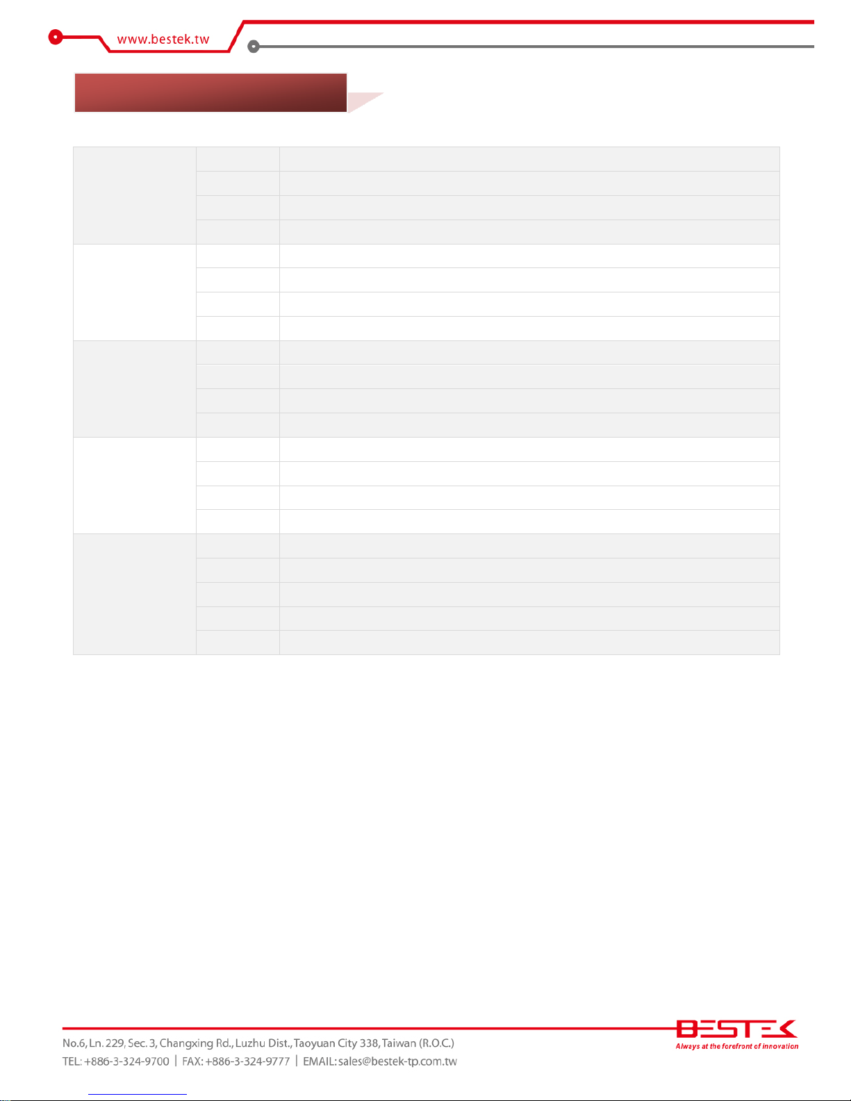
Core Engine
Chipset
Intel® H81 PCH
Processor
Support Intel® Gen-4 Core i3, i5, i7, Pentium® , Celeron® Processor
Single LGA1150 Processor Socket
Memory
2x DDR3 1066/1333 ECC/Non-ECC Unbuffered DIMM Slots, up to 16GB
ECC Memory only compatible with E3-1200 V3 Processor
Display
CPU Integrated
Ethernet
Controller
Onboard 6x Intel® 82574L, 2-Pair Bypass Function
LAN Module
Support 1x PCIe 3.0 X8 Slot for LAN Module
Storage
SATA
3x SATA
CF
1x CompactFlash Socket
Front I/O
Indication
1x Power LED, 1x HDD LED, 1x Status LED, 2x Bypass LEDs
LAN
6x RJ45 1G Ports
Console
1x RJ45 Type Console Port
USB
2x USB 2.0 Ports
Internal I/O
VGA
1x Internal VGA Pin Header
COM
1x COM2 Pin Header
PS/2
PS/2 Keyboard & Mouse Pin Header
USB
2x USB 3.0 Pin Header
Other
H/W Monitoring
Monitor temperature, voltage, and fan speed, auto-throttling control at CPU overheat
Environment
Operating Temp.
0oC ~ 60oC
Storage Temp.
-20oC ~ 70oC
Humidity
10% ~ 90% (Non-Condensing)
Mechanical
Dimension
192mm (W) x 265mm (D) x 1.6mm (H)
1.2 Specifications
10
BEM-H81-710-F2
Type
LAN Module
Chipset
Intel® XL710-AM2
Interface
PCIe 3.0 X8
Network Port
Two QSFP 40G
BEM-H81-710-F4
Type
LAN Module
Chipset
Intel® XL710-AM1
Interface
PCIe 3.0 X8
Network Port
Four SFP+ 10G
BEM-C600-599-F2
Type
LAN Module
Chipset
Intel® 82599ES
Interface
PCIe 2.0 X8
Network Port
Two SFP+ 10G
BEM-C600-580-F4
Type
LAN Module
Chipset
Intel® 82580EB
Interface
PCIe 2.0 X4
Network Port
Four SFP Fiber Gigabit
BEM-C600-580-C4
Type
LAN Module
Chipset
Intel® 82580EB
Interface
PCIe 2.0 X4
Network Port
Four RJ45 Gigabit
Bypass
1-Pair
1.3 Optional LAN Modules
11
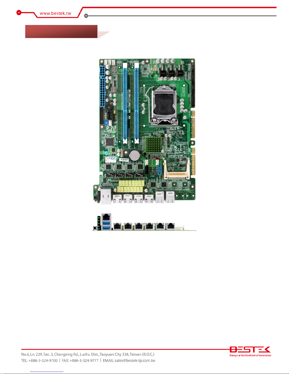
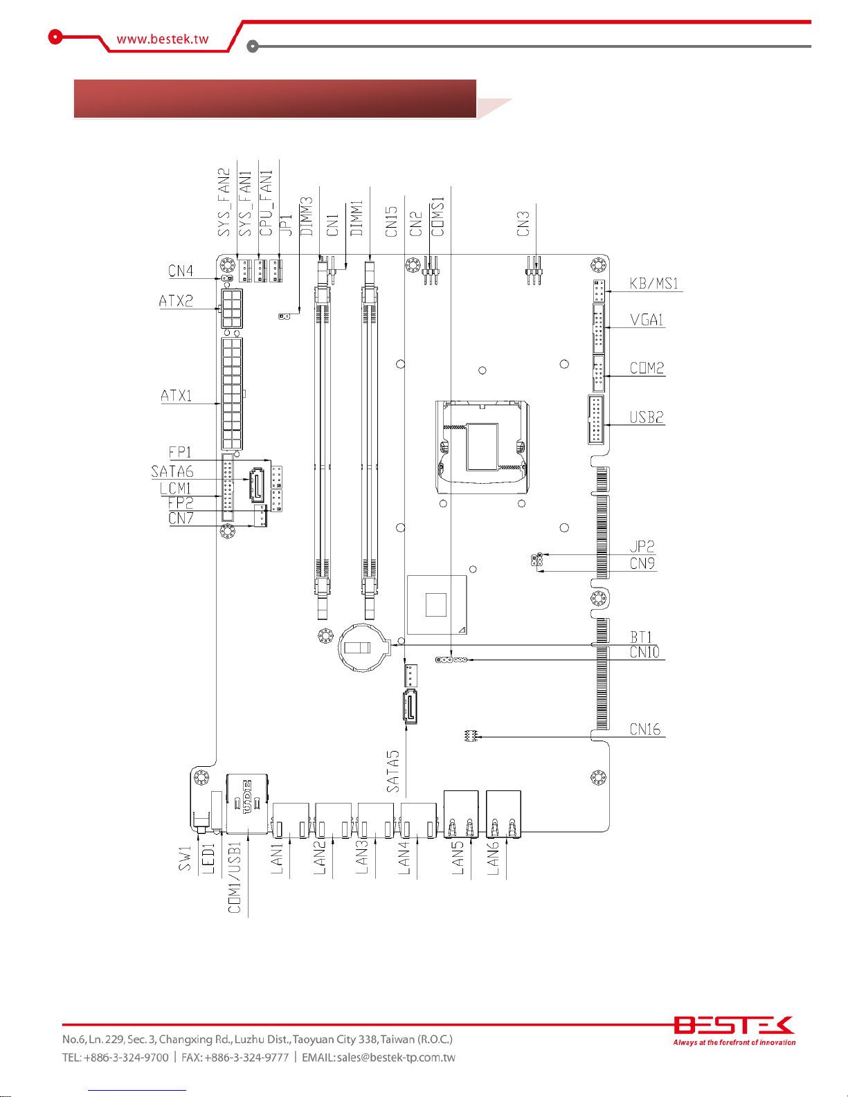
Figure 1.1: Board Layout of BNX-H81
1.4 Board Layout

12
Chapter 2
Preparation
13
A stable and clean working environment are essential. Dust and dirt can get into components and cause a
malfunction. Use containers to keep small components separated.
Adequate lighting and proper tools can prevent you from accidentally damaging the internal components. Most
of the procedures that follow require only a few simple tools, including the following:
A Philips screwdriver
A flat-tipped screwdriver
A set of jewelers Screwdrivers
A grounding strap
An anti-static pad
Using your fingers can disconnect most of the connections. It is recommended that you do not use needle-nosed
pliers to disconnect connections as these can damage the soft metal or plastic parts of the connectors.
Before working on internal components, make sure that the power is off. Ground yourself before touching any
internal components, by touching a metal object. Static electricity can damage many of the electronic
components. Humid environment tend to have less static electricity than dry
environments.
A grounding strap is
warranted whenever danger of static electricity exists.
Computer components and electronic circuit boards can be damaged by discharges of static electricity. Working
on the computers that are still connected to a power supply can be extremely dangerous. Follow the guidelines
below to avoid damage to your computer or yourself:
Always disconnect the unit from the power outlet whenever you are working inside the case.
If possible, wear a grounded wrist strap when you are working inside the computer case. Alternatively,
discharge any static electricity by touching the bare metal chassis of the unit case, or the bare
metal body
of any other grounded appliance.
Hold electronic circuit boards by the edges only. Never touch the components on the board unless it is
necessary to do so. Do not flex or stress the circuit board.
Leave all components inside the static-proof packaging that they shipped with until they are ready for
installation.
Use correct screws and do not over tighten screws.
2.1 Before You Begin
14
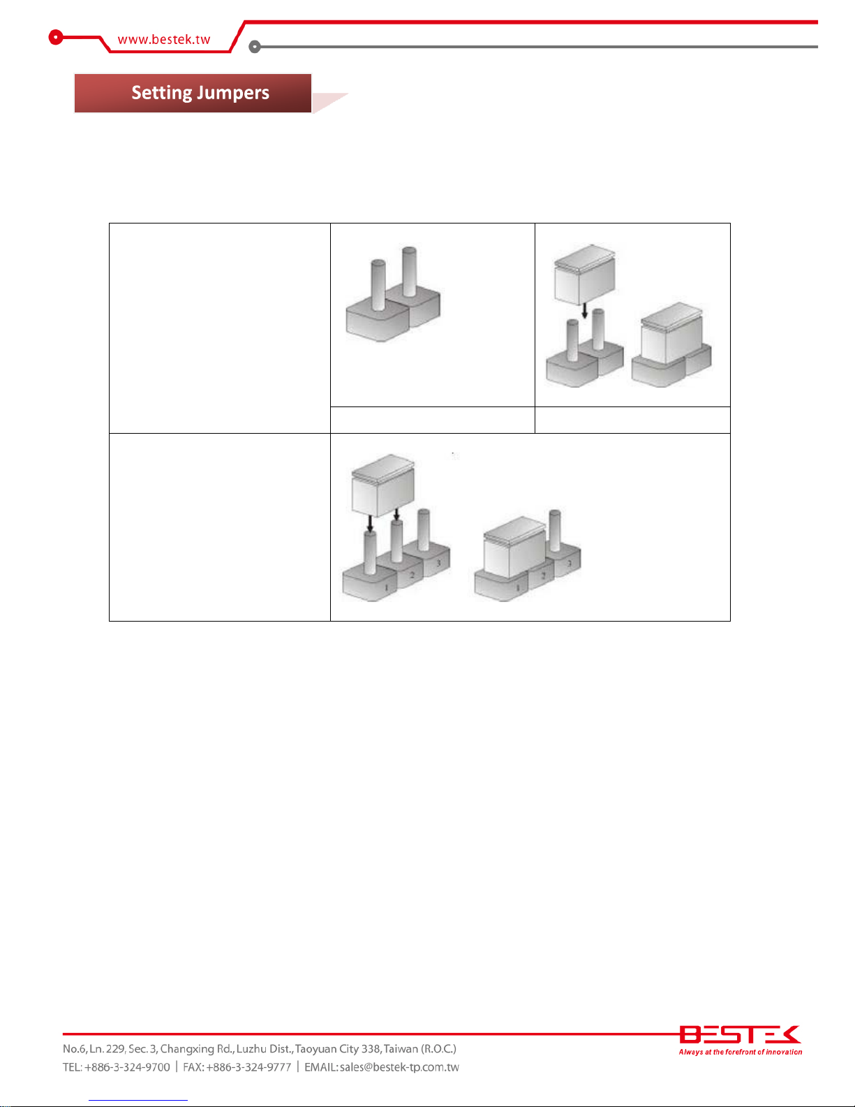
A jumper is the simplest kind of electric switch. It consists of two metal pins and a cap. When setting the jumpers,
ensure that the jumper caps are placed on the correct pins. When the jumper cap is placed on both pins, the
jumper is SHORT. If you remove the jumper cap, or place the jumper cap on just one pin,
the jumper is OPEN.
Please see the following illustrations
The illustrations on the right
show a 2-pin jumper. When the
jumper cap is placed on both
pins, the jumper is SHORT. If
you remove the jumper cap, or
place
the jumper
cap on just
one pin, the jumper is OPEN.
Open (Off)
Short (On)
These illustrations show a 3-pin
jumper. Pins 1 and 2 are SHORT.
Table 2-1: Setting
Jumpers
2.3
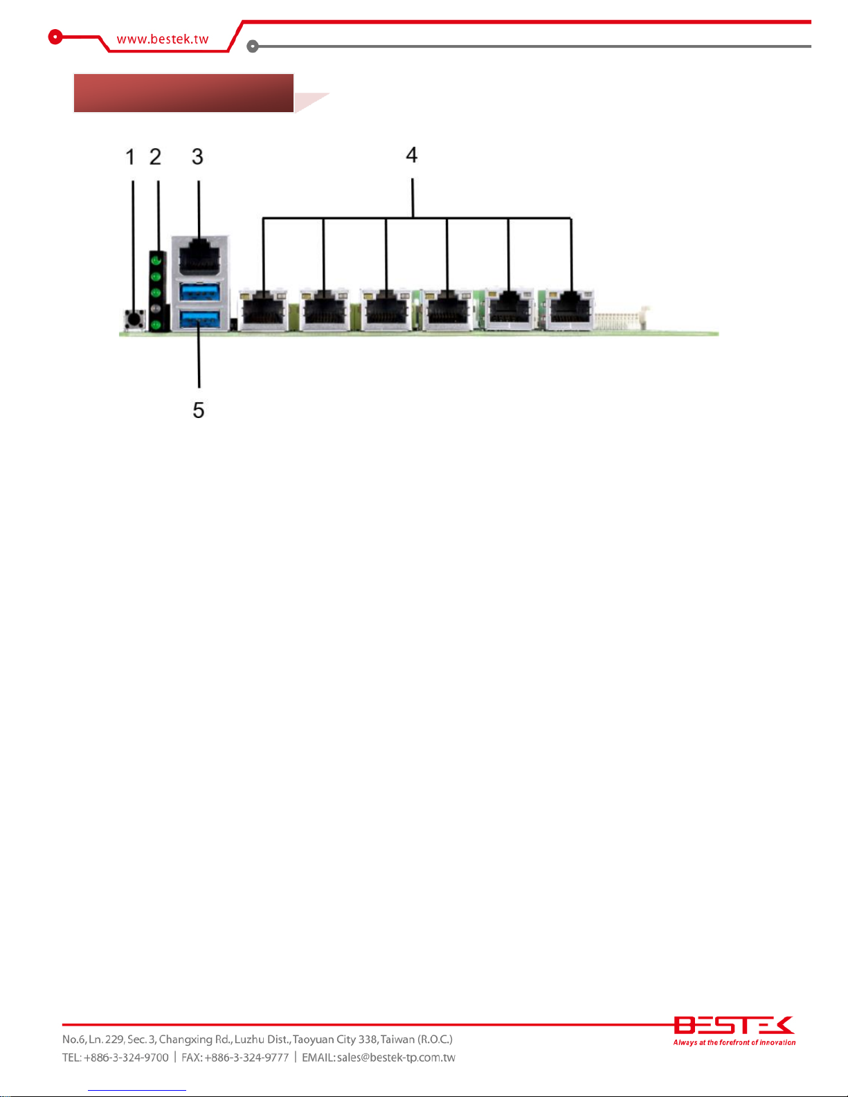
15
1. Programmable Switch
2. LED Indication
3. RJ45 Console Port
4. Six RJ45 Gigabit LAN Ports
5. Dual USB 3.0 Ports
2.4 Edge Connectors
16
2.5 Locations Of Jumpers and Connectors
 Loading...