

Page 1

Intelligent
Speed Dome Camera
User Manual
Page 2
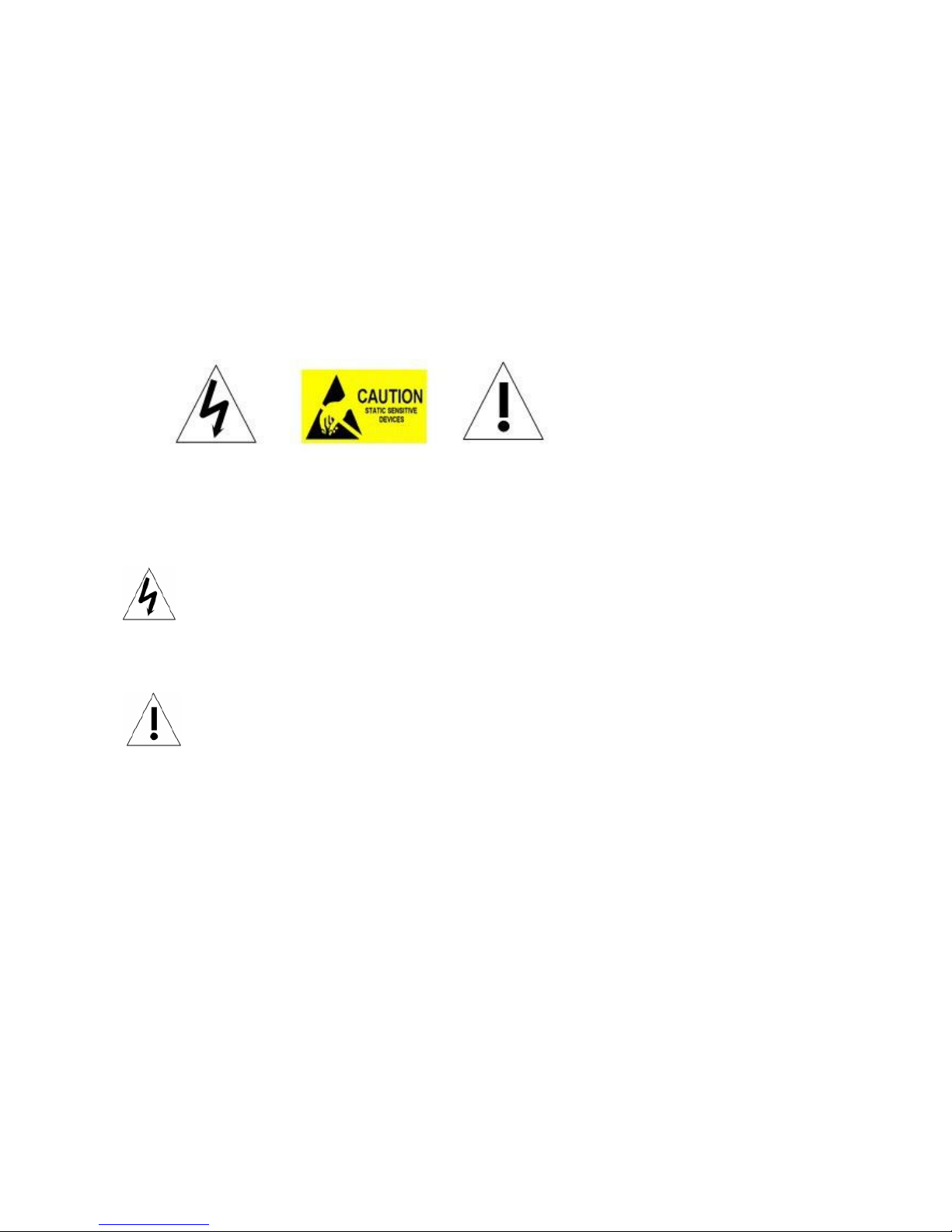
WARNINGS AND CAUTIONS
WARNING
TO REDUCE THE RISK OF FIRE OR ELECTRIC SHOCK, DO NOT EXPOSE THIS
PRODUCT TO RAIN OR MOISTURE. DO NOT INSERT ANY METALLIC OBJECTS
THROUGH VENTILATION GRILLS OR OPENINGS ON THE EQUIPMENT.
CAUTION
EXPLANATION OF GRAPHICAL SYMBOLS
The lighting flash with arrowhead symbol, within an equilateral triangle, is intended to
alert the user the presence of non-insulated “dangerous voltage” within the product’s
enclosure that maybe of sufficient magnitude to constitute a risk of electric shock to
different persons.
The exclamation point within an equilateral triangle, is intended to alert the user the
presence of important operating and maintenance (servicing) instructions in the
literature accompanying this product
Page 3

PRECAUTIONS:
1. Persons without technical qualifications should not attempt to operate this dome device before
reading this manual thoroughly.
2. Remove any power to the dome before attempting any operations or adjustments inside the
dome cover to avoid potential damage to the mechanism.
3. Inside the dome cover there are precision optical and electrical devices. Heavy pressure,
shock and other sudden adjustments or operations should be avoided. Otherwise, you may
cause irreparable damage to the product.
4. Please DO NOT remove or disassemble any internal parts of the video camera to avoid
normal operation and possibly void the warranty. There are no serviceable parts inside the
camera.
5. All electrical connections to the dome should be made in strict accordance with the attached
labels and wiring instructions in this manual. Failure to do so may damage the dome beyond
repair and void the warranty.
6. For outdoor installation especially in high places or poles, it is highly recommended that the
proper lightning arrestors and surge suppressors are installed before the dome is entered into
service.
7. Please do not use the product under circumstances where the limits exceed the maximum
specified temperature, humidity or power supply specifications.
Page 4

IMPORTANT SAFEGUARDS
1. Read these instructions before attempting installation or operation of dome device
2. Keep these instructions for future reference
3. Heed all warnings and adhere to electrical specifications Follow all instructions
4. Clean only with non abrasive dry cotton cloth, lint free and approved acrylic cleaners
5. Should the lens of the camera become dirty, use special lens cleaning cloth and solution to
properly clean it.
6. Do not block any ventilation openings. Install in accordance with manufacturer’s instructions
7. Use only attachments or accessories specified by the manufacturer
8. Verify that the surface you are planning to use for attaching the dome can adequately support
the weight of the device and mounting hardware
9. Protect this devices against lighting storms with proper power supplies
10. Refer all servicing to qualified service personnel. Servicing is required when the device has
been damaged in any way, when liquid traces are present, or the presence of loose objects is
evident or if the device does not function properly, or has received sever impact or has been
dropped accidentally.
11. Indoor dome is for indoor use only and not suitable for outdoor or high humidity locations.
Do not use this product under circumstances exceeding specified temperature and humidity
ratings.
12. Avoid pointing the camera directly to the sun or other extremely bright objects for
prolonged period of time avoiding the risk of permanent damages to the imaging sensor.
13. The attached instructions are for use by qualified personnel only. To reduce the risks of
electric shock do not perform any servicing other than contained in the operating instructions
unless you are qualified to do so.
14. During usage, user should abide by all electrical safety standards and adhere to electrical
specifications for the operation of the dome. The control cable for RS485 communications as
well as the video signal cables should be isolated from high voltage equipment and or high
voltage cables.
15. Use supplied power supply transformer only.
Page 5

INDEX
1 Product Introduction..........................................................................................................1
1.1 Package Contents..........................................................................................................1
1.2 Specification...................................................................................................................2
1.3 Function Description ......................................................................................................3
2 Installation.........................................................................................................................5
2.1 DIP Switch Settings .......................................................................................................5
2.1.1 Preparation ...................................................................................................5
2.1.2 Address Settings...........................................................................................6
2.1.3 Baud Rate Settings.......................................................................................6
2.1.4 RS-485 Bus Matching Resistance ................................................................6
2.2 Connection.....................................................................................................................7
3. Function Instruction..........................................................................................................8
3.1 Power Up Action ............................................................................................................8
3.2 Basic Function ...............................................................................................................8
3.3 Special Function ............................................................................................................9
3.4 Screen Character Operation ..........................................................................................9
4 OSD Menu ......................................................................................................................10
4.1 Menu Index ..................................................................................................................10
4.2 System Information ...................................................................................................... 11
4.3 Dome ...........................................................................................................................12
4.3.1 Communication...........................................................................................12
4.3.2 Guard Tours................................................................................................13
4.3.3 A-B Scan.....................................................................................................14
4.3.4 Pan Scan ....................................................................................................15
4.3.5 Park Action .................................................................................................15
4.3.6 Privacy Zone...............................................................................................16
4.3.7 Alarm (Optional)..........................................................................................17
4.3.8 Advanced....................................................................................................18
4.4 Camera ........................................................................................................................18
4.5 Language.....................................................................................................................19
4.6 Display .........................................................................................................................20
4.7 Reset ...........................................................................................................................21
5. Auto Temperature Control ..............................................................................................21
Appendix Ⅰ Anti-lightning, Anti-surge..............................................................................22
Appendix Ⅱ Clean Transparent Cover.............................................................................22
Page 6

Appendix Ⅲ Common Knowledge on RS-485 Bus ..........................................................23
1. Basic Feature of RS-485bus..........................................................................................23
2. Mode of Connection and Terminal Resistance...............................................................23
AppendixⅣ Address Code Mapping Table........................................................................23
Appendix Ⅲ Exception Handling ......................................................................................26
Copyright Statement ..........................................................................................................27
* Indicates the functions with default protocol, it might not function by using other protocols
※
Indicates the optional functions, only with certain mode
Page 7

1
1 Product Introduction
1.1 Package Contents
High Speed dome 1pc
Wall mount bracket 1pc
Power supply 1pc
Screws kits 1pc
User manual 1pc
Page 8

2
1.2 Specification
Horizontal Rotation Speed 200°/s
Tilt Rotation Speed 100°/s
Horizontal Rotation Range 360°
Tilt Rotation Range 93°
Auto Flip Horizontal 180°, Vertical 180°
Ratio Speed Support
PWR on Action Memory/NOP/A-B scan/360/Home/Tour 1-3
360° Scan Flip Range 0°-93° selectable
A-B Scan User programmable
A-B Scan Speed 01-64 speed selectable
A-B Scan Dwell 2-60s selectable
360° Scan Speed 01-64 grades
Dwell Preset 01-60s interval selectable
Preset Points 220
Go to Preset Speed 01-64 grades selectable
Guard Tours 3 groups (16 points / group)
Park Action Mode A-B scan/360/Home/Tour 1-3/Save action
Park Time 01-60mins selectable
Park Action User programmable
Communication Protocol Pelco-D, Pelco-P
Communication RS485 Bus
Baud Rate 1200/2400/4800/9600bps
Dome ID Dial ID on Dome: 001-255; Soft ID in Menu: 001-250
Page 9

3
Privacy Mask Support (only Sony, 24pcs settable)
Alarm 6 Inputs and 2 outputs (Optional)
OSD Menu Multiple Language (P/N customization)
Operating Temperature -40°~ +60°
Operating Humidity ≤95% Non Condensing
Heater & Blower Auto temperature control
Waterproof IP66
Power AC/DC15-28V ≤3A
Lightning Protection Transient voltage 6000V
Power Consumption ≤ 20W
Compatible Camera SONY, LG, CNB, SAMSUNG, etc.
1.3 Function Description
Super Communication
Address, baud rate and protocol could be changed both from Dip switch or from software.
Multilanguage OSD Menu
The language display on screen menu, the available language is English etc.. User can set the
function or parameter, or check the related information through the OSD.
Privacy Masking
In the monitoring scope, areas that users can’t or aren’t willing to make show in the screen of
the monitor can be set as privacy protected area (area masking), such as area where
customers enter the password in monitoring system of bank or some doorway.
Alarming Set
Details please refer to the OSD menu.
Focus
Page 10

4
The auto focus enables the camera to focus automatically to maintain clear image. User can
use manual focus to in special condition.
Under the following conditions camera will not auto focus on the camera target:
(1) Target is not the center of the screen;
(2) Attempting to view images that are far and near at the same time;
(3) Target is strongly lighted object, such as neon lamp, etc.;.
(4) Targets are behind the glass covered with water droplets or dust;
(5) Targets are moving quickly;
(6) Monotonous large area targets, such as wall;
(7) Targets are too dark or faint.
BLC
If a bright backlight is present, the target in the picture may appear dark or as a silhouette, BLC
enhance the target in the center of the picture, the dome uses the center of the pictures to
adjust the iris. if there is a bright light source outside this area, it will wash out to white, the
camera will adjust the iris so that the target in the sensitive area will properly exposed.
Iris Control
Factory default is automatic camera aperture, in mode of which camera senses changes in
ambient light through moving and adjust automatically lens aperture to make the brightness of
output image stable.
Users can through pressing OPEN or CLOSE iris adjusting keys, manually adjust the aperture
size to get the required picture brightness.
By controlling the keyboard up, down, left, right or zoom to resume auto iris (auto iris is
recommended).
Auto-recognize to Protocol and Module
The dome can auto-recognize to the corresponding protocol and module during self-inspection.
eg. Module: Sony, CNB, LG, Samsung, domestic etc.
Protocol: PELCO_P, PELCO_D etc.
3D Allocation
With this function users can move the image of some area to the center of screen according to
specified level and vertical coordinates and auto control to zoom according to zoom parameter
set.
Day/Night Switch
With auto day/night switch function, when the illumination is low, the picture will auto switch
from day to night mode and when the illumination is high enough, the picture will auto switch
from night to day mode.
Ratio Speed
Intelligent pan and tilt speed is variable depend on the zoom factor. When zooming in, the
speed will become slower and when zooming out, the speed will become quicker.
Page 11

5
A-B Scan
Dome circularly scan close-up real-time scene according to A-B points at setting speed in both
horizontal and vertical directions.
Pan Scan
Dome 360°clockwise continuous scan the display scene at setting speed in horizontal direction
under the condition that pitch angle remains the same.
Preset
After the dome camera keeps arbitrary PTZ location, it will automatically move to the defined
position when preset is called.
Guard Tour Scan
Dome patrol scans according to certain edited preset order.
Power Off Memory
This feature allows the dome to resume its previous preset or status after power is restored. By
default setting, the dome support power up memory, which improves the reliability and avoids
repeated settings of the parameter.
Park Action
If users don’t operate the dome in set time, it will automatically run preset specific mode (pan
scan, A-B scan, park action, cruise, preserve action etc.).
Zero Alignment
There is a point specified as zero point. When the dome is working, the preset point is not
accurate because of something caused by the operator. User can make the dome automatically
enable the zero alignment by operational order.
Auto Flip
In the manual tracking mode, when a target goes directly beneath the dome, the dome will
automatically rotate 180 degree in horizontal direction to maintain continuity tracking. When the
dome flips, the camera starts moving upward as long as you hold the joystick in the down
position.
2 Installation
2.1 DIP Switch Settings
2.1.1 Preparation
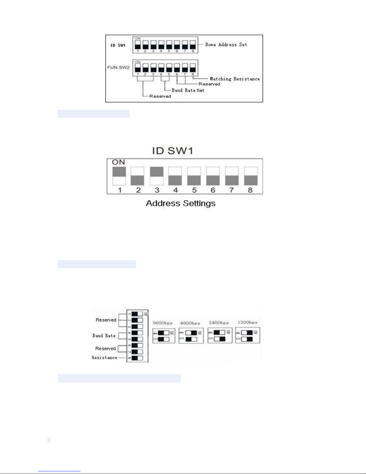
Before installation, make sure that the protocol , baud rate and address code used by the
product is fully consistent with the control system. Corresponding DIP switch site can be seen
below:
Page 12
6
2.1.2 Address Settings
DIP switch SW1 is the address settings of camera. It is a 8-bit switch, each switch corresponds
with 0 or 1 in the Binary code. OFF status means 0 while ON status means 1.
(See illustration above) Turn on the 1st and 3rd (allocated to ON position) and get the binary
code 00000101, so the correspondence address is 5.
Detailed settings please refer to the back “Address Code Mapping Table”(appendix Ⅳ).
2.1.3 Baud Rate Settings
The 4th and 5th DIP Switches set the Baud rate. Factory-default setting is 2400bps.
Baud rate: 1200bps、2400bps、4800bps、9600bps selectable
2.1.4 RS-485 Bus Matching Resistance
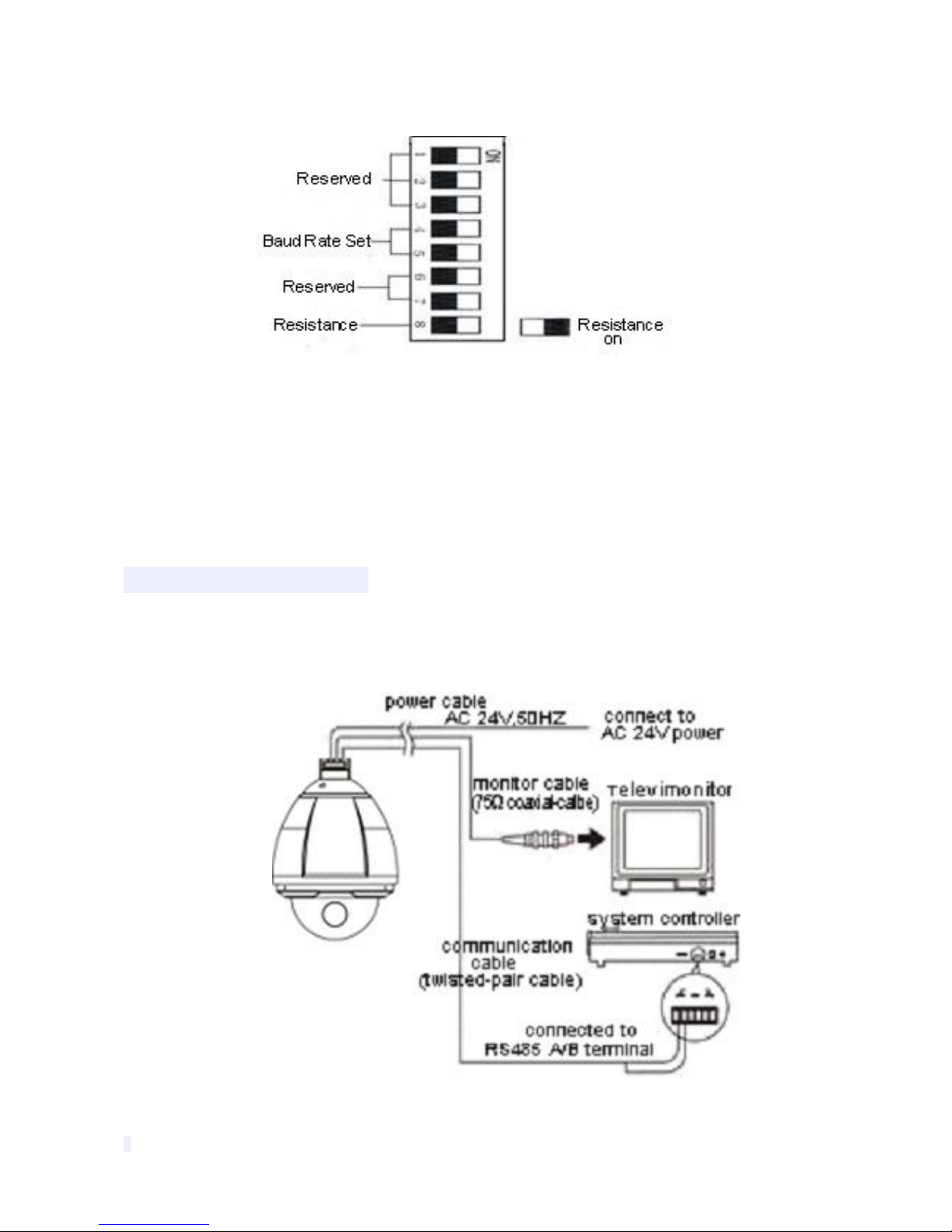
The 8th bit of DIP switch SW2 is to select the matching resistor. To the control center, in order to
prevent the reflection and interference of RS-485 communication signal and other signals, the
parallel matching resistor is needed in the communication interface of dome camera at the end
away from the control center.
Page 13
7
DIP switch SW2 has a control switch of matching resistor. That the 8th bit micro-switch turn to
the ON state (set as below) means having connected the matching electricity to RS-485 bus.
2.2 Connection
Connection of RS485
Before connecting, please turn off the power and read carefully the instructions of all connected
devices.
Page 14

8
Fig 24
3. Function Instruction
3.1 Power Up Action
Power Up Self Testing Pan, Tilt, Camera Self-test Completion
Pan action: Pan rotate in certain direction and stop in zero coordinate.
Tilt action: Tilt rotate in certain direction and stop in zero coordinate.
Lens action: Lens zooms out to the widest angle.
From running the above actions to completing, power up self-testing finishes.
3.2 Basic Function
Dome Running
Control joystick or up, down, left and right key in the keyboard.
Zoom
Press ZOOM- button to make the lens farther and minify the scene.
Press ZOOM+ button to make the lens closer and magnify the scene.
Focus
After FOCUS- button is pressed, the object in vicinity will become clearer while the object far
away will become ambiguous.
After FOCUS+ button is pressed, the object far away will become clearer while the object in
vicinity will be ambiguous.
Iris
Press IRIS- to gradually shrink the iris and decrease the image brightness.
Press IRIS+ to enlarge the iris and increase the image brightness.
Preset Point
Setting preset press button “preset”+”number”+”enter”.
Calling preset press button “call”+”number”+”enter”.
<SYSTEM>
MFG
PROTOCOL ATUO
DOME ID
COMM
VERSION
DETECTING
<SYSTEM>
MFG
PROTOCOL ATUO
DOME ID
COMM
VERSION
PAN: XXX TILT: XXX
Page 15

9
Deleting preset press button “clear”+”number”+”enter”.
Remark:
Some preset points are used tentatively for special functions.
3.3 Special Function
The follow presets are predefined as special function, please shot+ preset No+ enter to enable
those functions:
Remark
: If use some other equipments to control speed dome, some special functions
probably can’t be effective because of the limite of protocol.
3.4 Screen Character Operation
Call preset 95 to
enter the OSD, call preset 94 to exit the OSD.
Up or Down : Move the option of the OSD, change the value on the OSD.
Right :Enter the option, select the item or confirm.
Left:Return to main menu or cancel
Angle Display: XXX.XX(pan)/XXX.XX(tilt)
COMM. Display: Display the dome ID and baud rate on the top left corner of the
screen.
Remark:
1. Items with“< >” mean they have sub menu.
2. “→”means the cursor selecting some option.
3. “※” means editing the content of some option selected.
4. When entering the setting page in menu, it is useless to call preset 94 to exit the
menu directly. Such as the submenu <SET> in menu <GUARD TOUR SET>.
PREST
FUNCTION
PRESET
FUNCTION
33
Pan scan180
º 88
Freeze on
34
Reset
89
Freeze off
79
Digital zoom on
92 A-
B scan
80
Digital zoom off
94
OSD off
81
Auto day/night
95
OSD on
82
Switch to night
96
Guard tour 3
83
Switch to day
97
Guar
d tour 2
86
BLC on
98
Guard tour 1
87
BLC off
99
Pan scan
Page 16
10
4 OSD Menu
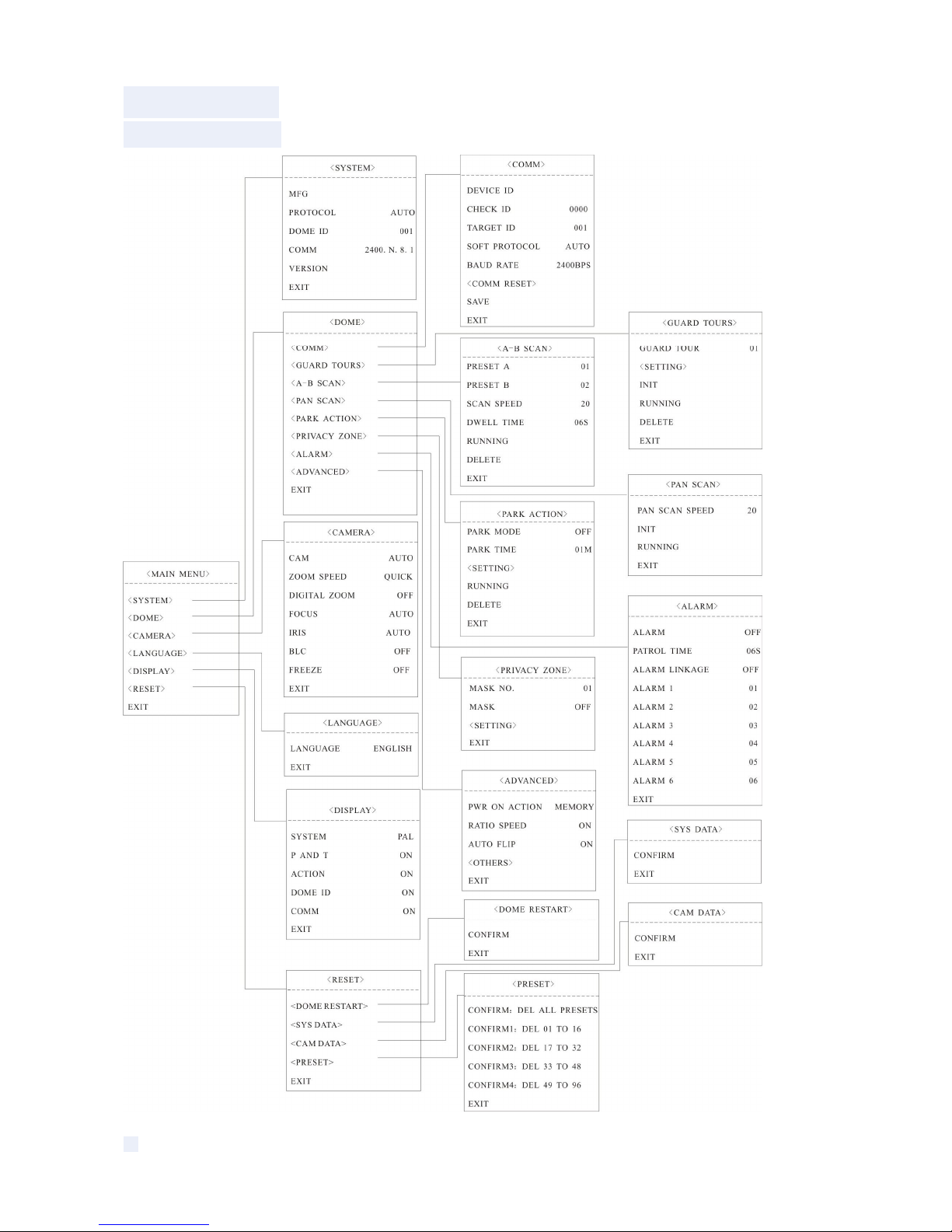
4.1 Menu Index
Page 17

11
fig 4.1.1 Get into the Menu Screen
4.2 System Information
Fig 4.2.1
MFG:Max 15 characters display on the screen.
PROTOCOL:Display the protocol of the dome
<MAIN MENU>
<SYSTEM>
<DOME>
<CAMERA>
<LANGUAGE>
<DISPLAY>
<RESET>
EXIT
<SYSTEM>
MFG
PROTOCOL AUTO
DOME ID 001
COMM 2400.N.1
VERSION
EXIT
Page 18

12
DOME ID:Display the dome address.
COMM: Form: Baud rate. Check bit. Data bit. Start bit
VERSION: Version will update along with the product upgrading
Remark:
Protocol, ID and COMM all can be set in menu <COMM>.
4.3 Dome
Fig 4.3.1
4.3.1 Communication
Fig 4.3.1.1 Fig 4.3.1.2
DEVICE ID
<DOME>
<COMM>
<GUARD TOURS>
<A-B SCAN>
<PAN SCAN>
<PARK ACTION>
<PRIVACY ZONE>
<ALARM>
<ADVANCED>
EXIT
<COMM>
DEVICE ID
CHECK ID 0000
TARGET ID 001
SOFT PROTOCOL AUTO
BAUD RATE 2400BPS
<COMM RESET>
SAVE
EXIT
<COMM RESET>
COMM RESET TO HARD DIP SET
YES
EXIT
Page 19

13
It is only and used to distinct from the ID of other domes.
CHECK ID
Distinguishing several domes with same ID and altering target ID, soft protocol and baud rate
need to enter check ID in line with the device ID, otherwise altering can’t be completed.
TARGET ID
Target ID is available from 001 to 250.
SOFT PROTOCOL
Soft protocol is auto, Pelco-D and Pelco-P available
BAUD RATE
1200BPS、2400BPS、4800BPS、9600BPS available
COMM RESET
As shown in fig 4.3.3.2, carry out YES to reboot the dome and communication reset to DIP set
hard ID and hard baud rate.
SAVE
Please save the change of communication. After saving, the dome will reboot.
Remark:
The out-of-factory default of dome camera is hardware DIP set. After the COMM. is
changed in menu, it can’t be effective until saved. If needing to get hardware DIP set again, run
the COMM RESET.
4.3.2 Guard Tours
Fig 4.3.2.1 Fig 4.3.2.2
GUARD TOUR
Total 3 guard tours selectable: 01, 02, 03.
<GUARD TOURS>
GUARD TOUR 01
<SETTING>
INIT
RUNNING
DELETE
EXIT
<GUARD TOUR 01>
ID POINT TIME(S) SPEED
1 01 06 64
2 02 06 64
3 03 06 64
4 04 06 64
5 05 06 64
6 06 06 64
7 07 06 64
8 08 06 64
Page 20

14
SETTING
Each guard tour includes max 16 presets. The number of the preset is from 0-64. 0 is not valid,
dwell time is 1 to 60s selectable. Speed is 1 to 64 grades selectable.
INIT
After init., preset point, dwell time, speed will resume to default setting.
RUNNING
Running the present guard tour.
DELETE
Delete the guard tour set. After deleting, the present preset points all display as 0. While the
exact preset point information doesn’t be deleted. So it is convenient for user to select the
preset point needing to be guarded tour.
4.3.3 A-B Scan
Fig. 4.3.3.1 Fig. 4.3.3.2
PRESET A
On A-B scan, A point can be preset from 0 to 64.
PRESET B
On A-B scan, B point can be preset from 0 to 64.
SCAN SPEED
A-B scan speed is 1 to 64 grade selectable.
DWELL TIME
Dwell time between A to B is 2s to 60s selectable.
RUNNING
Running the A-B scan. Check Fig. 4.3.4.2.
DELETE
<A-B SCAN>
PRESET A 01
PRESET B 02
SCAN SPEED 20
DWELL TIME 06S
RUNNING
DELETE
EXIT
A-B SCAN
RUNNING…
LEFT KEY TO EXIT
PAN:XXX TILT:XX
Page 21

15
After deleted, the preset points display as 0. While the exact preset point information doesn’t be
deleted. So it is convenient for user to select the preset point needing to be scanned. Speed
and dwell time will reset as default setting.
4.3.4 Pan Scan
Fig. 4.3.4.1 Fig. 4.3.4.2
PAN SCAN SPEED
Pan scan speed is 1 to 64 grade selectable.
INIT
Reset the scan speed and tilt degree as default setting.
RUNNING
Running the scan speed and tilt degree set.
4.3.5 Park Action
Fig. 4.3.5.1 Fig. 4.3.5.2
PARK MODE
Park mode includes OFF, Park action, A-B scan, Pan scan, guard tour01, guard tour02, guard
tour03 and Preserve action.
When park mode is OFF status, the dome doesn’t run park mode.
<PAN SCAN>
PAN SCAN SPEED 20
INIT
RUNNING
EXIT
PAN SCAN
RUNNING…
LEFT KEY TO EXIT
PAN:XXX TILT:XX
<PARK ACTION>
PARK MODE OFF
PARK TIME 01M
<SETTING>
RUNNING
DELETE
EXIT
<PARK ACTION>
PRESET 1: SAVE
PRESET 2: BACK
Page 22

16
When park mode is PRESERVE ACTION status, it record previous action order(A-B scan, Pan
scan, Guard tour 01, Guard tour 02, Guard tour 03).
Example: Running A-B scan at first, when the action stops unexpectedly, it enters the park
mode to continue to run A-B scan.
PARK TIME
Park time is 01~60 mins selectable.
SETTING
After entering the OSD menu, as 7.4.8.2, move to the desired position and save the settings.
RUNNING
Running the park action, if there is no setting, system will remind of it . Please set park action.
DELETE
Delete the settings.
4.3.6 Privacy Zone
Fig. 4.3.6.1 Fig. 4.3.6.2 Fig. 4.3.6.3
MASK NO.
Mask No. depends on the number of the module supported. The selective range of Sony is
from 1 to 24.
MASK
Mask has on and off selectable.
SETTING
Set the specific parameter of present mask NO. and call preset 1 to save the settings.
Direction operation—Modify the coordinate of dome
Zoom operation—Modify the size of scenery
Iris operation—Modify the size of privacy zone
Remark
: The mask size is better more than double the target size. If needing to modify mask
<PRIVACY ZONE>
MASK NO. 01
MASK OFF
<SETTING>
EXIT
<PRIVACY ZONE>
PRESET 1: SAVE
<PRIVACY ZONE>
PRIVACY PROPOSED TO
OPEN
Page 23

17
NO.02, set it again. If needing to stop it, set mask to OFF status.
If the module doesn’t support privacy mask, the screen will display the interface as Fig. 4.3.6.3.
4.3.7 Alarm (Optional)
Fig. 4.3.7.1
ALARM
Alarm has OFF and ON selectable.
PATROL TIME
Patrol time is 2~60s selectable.
ALARM LINKAGE
Alarm linkage has OFF and ON selectable.
ALARM 1
To run alarm 1, presets 1-64 are available.
ALARM 2
To run alarm 2, presets 1-64 are available.
ALARM 3
To run alarm 3, presets 1-64 are available.
ALARM 4
To run alarm 4, presets 1-64 are available.
<ALARM>
ALARM OFF
PATROL TIME 06S
ALARM LINKAGE OFF
ALARM 1 01
ALARM 2 02
ALARM 3 03
ALARM 4 04
EXIT
Page 24

18
4.3.8 Advanced
Fig. 4.3.8.1
PWR ON ACTION
Power on action can be set as Memory, A-B scan, Pan scan, Park action, Guard tour 01, Guard
tour 02, Guard tour 03 and No action.
RATIO SPEED
Ratio speed can be set as ON or OFF status.
AUTO FLIP
Auto flip can be set as ON or OFF status.
OTHERS
Set other options.
4.4 Camera
Fig. 4.4.1
<ADVANCED>
PWR ON ACTION MEMORY
RATIO SPEED ON
AUTO FLIP ON
<OTHERS>
EXIT
<CAMERA>
CAM AUTO
ZOOM SPEED QUICK
DIGITAL ZOOM OFF
FOCUS AUTO
IRIS AUTO
BLC OFF
FREEZE OFF
EXIT
Page 25

19
CAM
Display the information of module supported by this dome.
ZOOM SPEED
Zoom speed is quick and slow selectable.
DIGITAL ZOOM
Digital zoom is on/off selectable.
FOCUS
Focus is auto and manual selectable
IRIS
Iris is auto and manual selectable
BLC
BLC is ON and OFF selectable
FREEZE
Video freeze is ON and OFF selectable
Remark
: Only if those functions are available on the present module, the user can use it.
4.5 Language
Fig. 4.5.1
LANGUAGE
Language can be set as Chinese or English. Default settings is English.
<LANGUAGE>
LANGUAGE ENGLISH
EXIT
Page 26

20
4.6 Display
Fig. 4.6.1
SYSTEM
Video system includes NTSC and PAL. N means NTSC and P means PAL.
P AND T
On screen, it displays the pan and tilt degree, user can enable or disable it.
ACTION
On the screen, it displays the current action, such as A-B scan, Call preset, Save preset, Call
park action, Pan scan etc. User can enable or disable it
DOME ID
At the top left corner of screen, it displays the dome ID. User can enable or disable it.
COMM
At the top left corner of screen, it displays the dome communication information. User can
enable or disable it.
<DISPLAY>
SYSTEM PAL
P AND T ON
ACTION ON
DOME ID ON
COMM ON
EXIT
Page 27
21
4.7 Reset
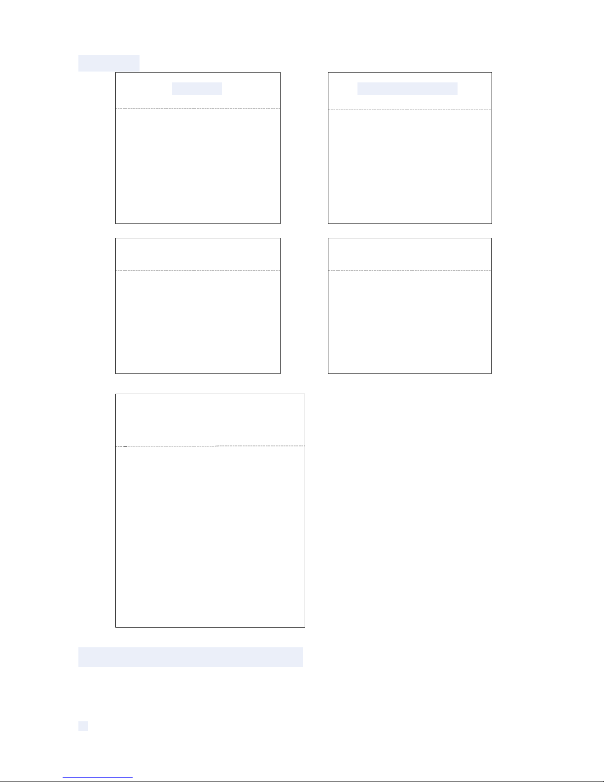
CONFIRM: Delete the presets information
saved by the dome.
5. Auto Temperature Control
This product has built-in fan and heater, which accordingly cool or heat through temperature
sensitive circuit inside the dome.
<RESET>
<DOME RESTART>
<SYS DATA>
<CAM DATA>
<PRESET>
EXIT
<DOME RESTART>
CONFIRM: Save data,
dome restart
EXIT
<SYS DATA>
CONFIRM:Factory default
EXIT
<CAM DATA>
CONFIRM:Factory default
EXIT
<PRESET>
CONFIRM: DEL ALL PRESETS
CONFIRM 1: DEL 01 TO 16
CONFIRM 2: DEL 17 TO 32
CONFIRM 3: DEL 33 TO 48
CONFIRM 4: DEL 49 TO 96
EXIT
Page 28
22
Appendix
Ⅰ
Anti-lightning, Anti-surge
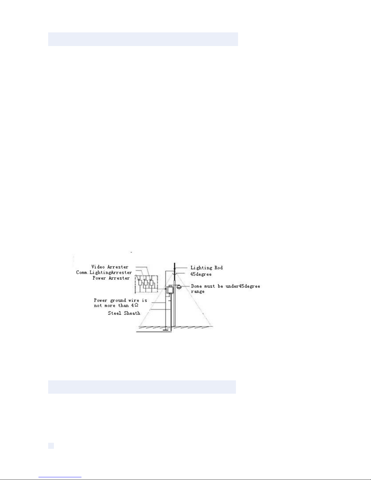
This product is extremely air discharge and lightning protection with TVS tube technology,
which can effectively prevent the transient lightning below voltage 3000V, surge and damages
caused by other types of pulse signals.
However, necessary protective measures should be made in the premise of ensuring
electrical safety for outdoor installation according to the actual situation :
·Signal transmission line must be at least 50 meters far away from the high-voltage
equipment or high voltage cable.
· Try to choose outdoor wiring laid down along the roof line.
· Way of sealed steel pipe buried wiring is used in the area which opened, and steel pipe
units grounded in one point. Overhead wiring is absolutely prohibited.
· In the strong thunderstorms area or areas with high induced voltage (such as high voltage
substations), measure of installation of additional high power lightning protection equipment
and lightning rod must be taken.
· Lightning protection and grounding of outdoor devices and lines must take the
lightning-protection requirements of buildings into consideration, and comply with the related
national standards and industry standards.
· System must be equipotential grounding. Grounding device must meet dual requirements
of anti-interference and electrical safety, and should not be shorted or mixed with the adjacent
lines in the strong power grid. When system is independently grounded, grounding impedance
should be less than 4Ω, and cross-sectional area of grounding conductor must be not less than
25m2.
Fig 25
Appendix
Ⅱ
Clean Transparent Cover
In order to assure a clear image of dome, the under cover of dome should be cleaned regularly.
● Be careful when cleaning and hold the outer ring of under cover by hands to avoid directly
touching with it. Because the acid sweat of finger membrane may corrode the surface coating
of under cover. Hard tool scratching the under cover may lead to blurring the images of dome
so that affecting image quality.
Page 29
23
● Please use a soft enough dry cloth or other alternatives to wipe internal and external surface.
● If dirt is serious, user can use a mild detergent. Any senior furniture cleaning products can be
used to clean the under cover.
Appendix
Ⅲ
Common Knowledge on RS-485 Bus
1. Basic Feature of RS-485bus
According to industry bus standard of RS-485, RS-485 bus is half-duplex communication bus
with the characteristic impedance of 120Ω, whose maximum load capacity is 32 payloads
(including the master device and the controlled device).
2. Mode of Connection and Terminal Resistance
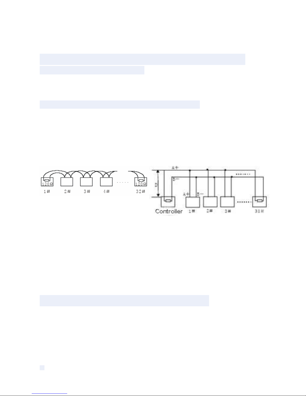
2.1 Industry standard of RS485 bus requires that connection mode of daisy chain should be
used between the devices with 120Ω terminal resistances connected at the both ends.
As shown in fig. 26 and fig. 27 is simplified connection, but the distance of part "D" shall not
beyond 7 meters.
Fig 26 Fig 27
2.2 120Ω terminal resistance is connected as shown in fig 27.
120Ω terminal resistance is available in the circuit board and the connection is shown as
following:
When needing to connect 120Ω resistance, toggle the 8th bit of DIP switch SW2 to "ON" . This
way the 120Ω resistance is connected to the circuit.
AppendixⅣ Address Code Mapping Table
SW1 DIP Switch sets the dome address, which using binary encoded. The 8th is the top bits,
and 1st is the lowest bits.
Toggle the code bits of DIP Switch to ON, then the corresponding location is “1”. Conversely, it’s
“0”.
Page 30

24
Following is a dome address code mapping table to set PELCO_D:
Switch Settings
Address
SW1
-1
SW1
-2
SW1
-3
SW1
-4
SW1
-5
SW1
-6
SW1
-7
SW1
-8
0 OFF
OFF
OFF
OFF
OFF
OFF
OFF
OFF
1 ON
OFF
OFF
OFF
OFF
OFF
OFF
OFF
2
OFF
ON
OFF
OFF
OFF
OFF
OFF
OFF
3 ON ON OFF OFF
OFF
OFF
OFF
OFF
4
OFF
OFF
ON
OFF
OFF
OFF
OFF
OFF
5 ON
OFF
ON
OFF
OFF
OFF
OFF
OFF
6
OFF
ON ON
OFF
OFF
OFF
OFF
OFF
7 ON ON ON
OFF
OFF
OFF
OFF
OFF
8
OFF
OFF
OFF
ON
OFF
OFF
OFF
OFF
9 ON
OFF
OFF
ON
OFF
OFF
OFF
OFF
10
OFF
ON
OFF
ON
OFF
OFF
OFF
OFF
11 ON ON
OFF
ON
OFF
OFF
OFF
OFF
12
OFF
OFF
ON ON
OFF
OFF
OFF
OFF
13 ON
OFF
ON ON
OFF
OFF
OFF
OFF
14
OFF
ON ON ON
OFF
OFF
OFF
OFF
15 ON ON ON ON
OFF
OFF
OFF
OFF
16
OFF
OFF
OFF
OFF
ON
OFF
OFF
OFF
17 ON
OFF
OFF
OFF
ON
OFF
OFF
OFF
18
OFF
ON
OFF
OFF
ON
OFF
OFF
OFF
19 ON ON
OFF
OFF
ON
OFF
OFF
OFF
20
OFF
OFF
ON
OFF
ON
OFF
OFF
OFF
21 ON
OFF
ON
OFF
ON
OFF
OFF
OFF
22
OFF
ON ON
OFF
ON
OFF
OFF
OFF
23 ON ON ON
OFF
ON
OFF
OFF
OFF
24
OFF
OFF
OFF
ON ON
OFF
OFF
OFF
25 ON
OFF
OFF
ON ON
OFF
OFF
OFF
--- ---- ----
---- ---- ---- ---- ---- ---- 251 ON ON OFF
ON ON ON ON ON
252 OFF
OFF
ON ON ON ON ON ON
253 ON OFF
ON ON ON ON ON ON
254 OFF
ON ON ON ON ON ON ON
Page 31

25
Following is a dome address code mapping table to set PELCO_P:
Switch Settings
Address
SW1
-1
SW1
-2
SW1
-3
SW1
-4
SW1
-5
SW1
-6
SW1
-7
SW1
-8
Page 32
26
Appendix
Ⅲ
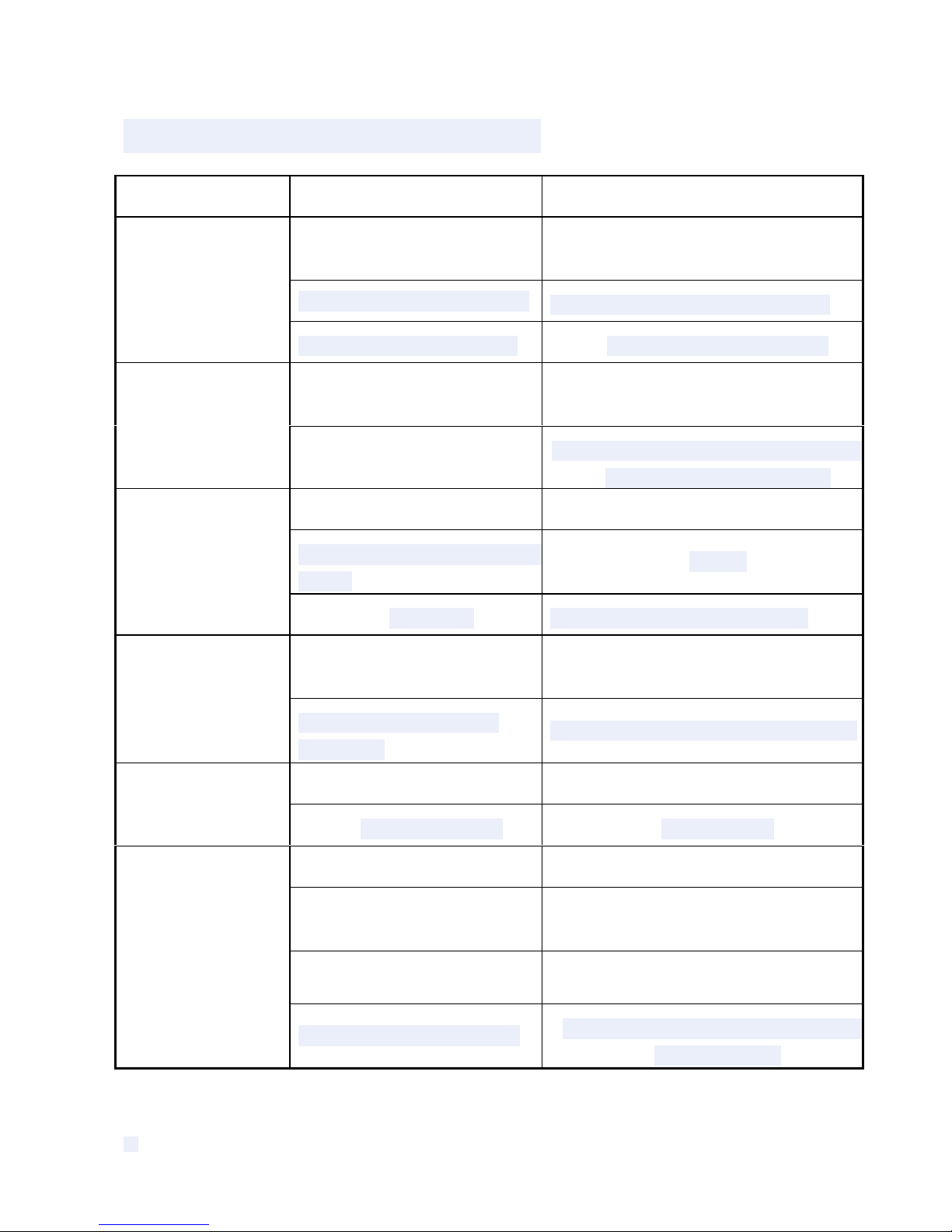
Exception Handling
Issue Possible Reason Solution
Cable harness is improperly
connected
Verify that the orientation of the
connector input
Input power voltage is too low
Verify the voltage of the input power
After power is applied,
there is no action
(self-test)
and no video image.
Power supply does not work Change a new power supply
Wrong communication
settings
Set the correct protocol, baud rate and
address of dome device
Self-test is
normal, but dome
cannot be
controlled.
Improper connection of
control cable (polarity)
Verify the p
olarity of the RS485 connection
as per the instruction manual
Mechanical obstruction Verify and correct it
Camera module is not installed
correct
Correct
Noise after
self-testing
Low power Change the correct power supply
Low power
Check the power supply or make sure
the power input is AC 24V
Image is not
stable
Video cable is improperly
connected.
Verify the connection of the video cable
Camera is on manual focus Change to auto focus Image is
blurring
The lens is dusted Clean the lens
Power is too low Change the AC 24V Power supply
Communication distance is
too long
Make sure the distance is in the
allowed range
RS485 cable is not properly
connected.
Make the RS485 is properly connected.
Controlling
the dome is
not smooth
Too many domes connected
Make sure the connected dome is in the
allowed quantity
Page 33

27
Copyright Statement
This copyright is merely belong to the manufacturer. Without permission, please don’t
plagiarize or copy the contents of this book in any form or by any means.
The company follows the policy of continuous development. Therefore, the company reserves
the right to modify or improve the products described in this manual without notice.
The content of manual is offered according to the "current state". Unless applicable law
otherwise specified, the company does not make any kind of clear or tacit reassurance about
the accuracy, reliability and contents of this manual. The company reserves the right to revise
or recoup this manual at any time without notice.
 Loading...