

Page 1
Page 2
Page 3
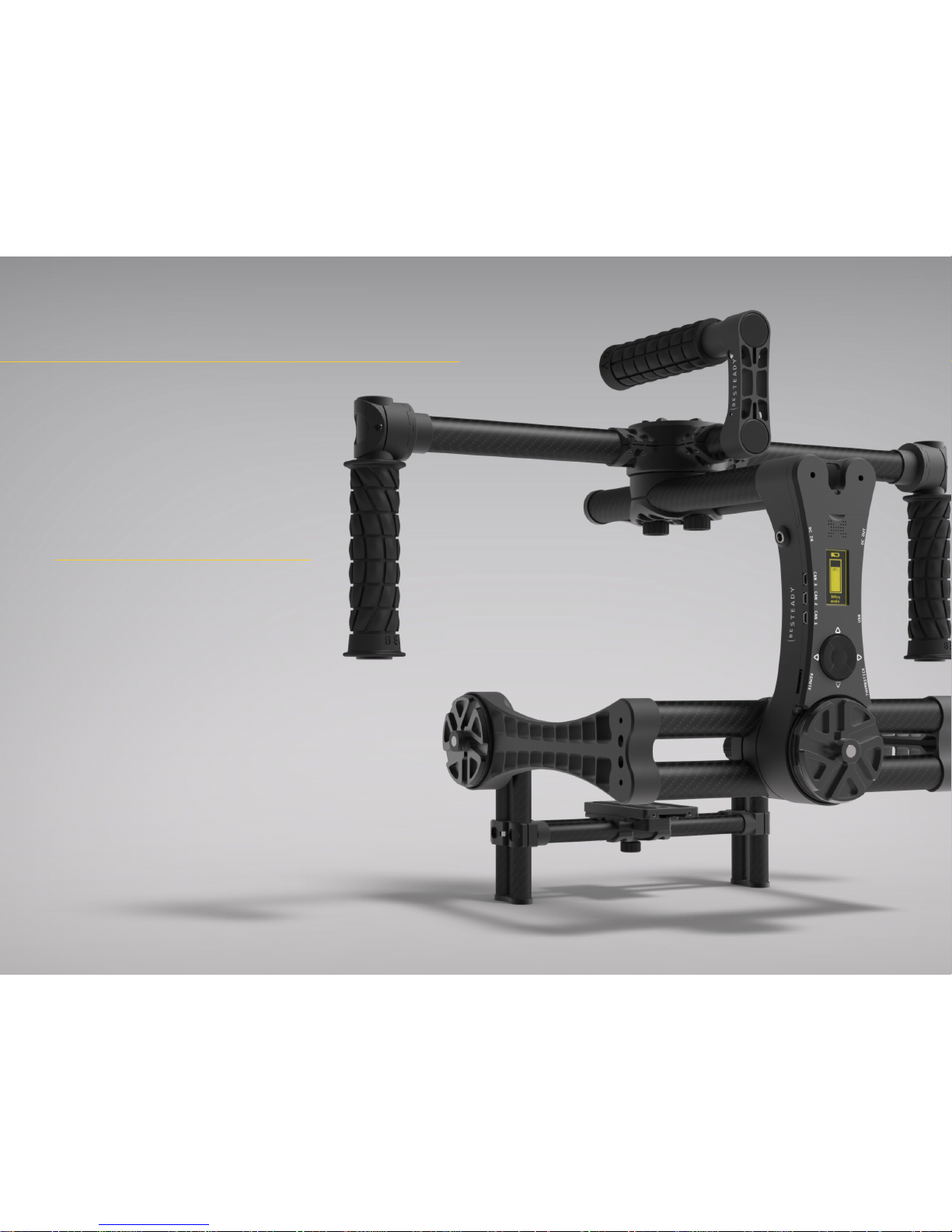
HERE IT IS!
A
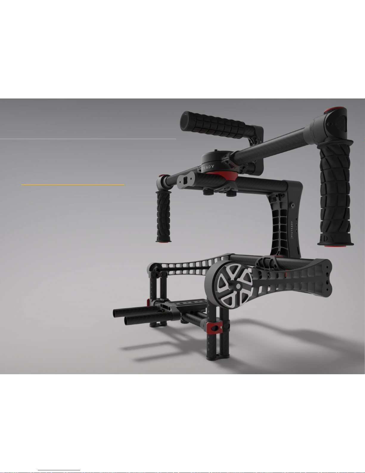
fter the long road The Beast is nally in your hands. BeSteady FOUR combines state-of-the-art technology with
eye-catching form of design and beauty. Featuring a hybrid combination of sensors (IMUs) and optical encoders The
Beast delivers a completely new approach on how the 3-axial camera stabilisation works, making your framing very
cinematic and simply natural. Fully congurable through a built-in conguration system consisitng of a sharp OLED
screen, control keyboard and OnBoard Manager, the FOUR redenes the workow with a professional gimbal. Toolless
balancing system, Lock’n’Load quick-detach function, ability to power up cameras and equipment alike straight from
the main power source, heavy-duty construcion, adaptable payload ranging from small DSLRs to production cameras
and much more - this is what a cine stabiliser is supposed to be.
Page 4
GETTING STARTED
T
he Beast emerged from its smaller predcessor, the BeSteady ONE. The goal was to cre-
ate the ultimate stabiliser for cine setups.
It represents a combination of our deep passion,
months of research, development and testing.
Not to mention an incredible attention to detail.
The result is a stabiliser that offers a new world
of possibilities for today’s demanding lmmaker. The potential for innovation and creative
applications is endless, and we couldn’t be
more excited to see how our users will surprise us.
This Manual will teach you how to setup,
balance, and congure your BeSteady FOUR.
First steps in operating a handheld gimbal
are rather easy to complete but mastering
your skills and achieving perfect results
may take time. Bear in mind that the tool
itself will not make a fresh cameraman
to become a professional in a blink of an
eye. Great results come with practice and
this tool is designed to provide amazing
footage for talented and experienced
operators.
THE BEAST
4
Page 5

1 Getting started
Elements of the system
Before you start
Charging the batteries
Connecting the batteries
Batteries maintenance
Using the Lock’n’Load
Connection ports
Using the XL stand
Mounting the camera
2 Balancing the FOUR
Tilt axis front-to-back balance
Tilt axis Center of Gravity balance
Roll axis balance
Pan axis balance
3 The OnBoard Manager
Launching The Beast
Navigation
The summary screen
Menu walkthrough
Service Mode
Using USB / BlueTooth connection for external software
4 Operating Modes
Xtended Stabilisation
Follow Mode
Slim Side Mode
Inverted Mode
Frame Invert
Remote Control
Default MZ-12 RCU setup
BeSteady Thumbstick setup
CONTENTS
5
Page 6
Getting started
A
handheld stabiliser is an advanced product and requires practice
to get used to and master. Please, take some time to follow the
general guidelines before using your BeSteady FOUR to make
your operating experience as smooth and enjoyable as possible.
DISCLAIMER
All information and instructions in this document are subject to
change without notice.
This is a sophisticated cinema product. It must be operated with
caution and common sense and requires some basic mechanical
knowledge. Failure to operate this product in a safe and responsible manner could result in injury or damage to the product or
other property. This Manual contains instructions for safety and
operation. It is essential to read the entire Manual and follow all
instructions and warnings in the manual, prior to setup or use,
in order to operate the BeSteady FOUR correctly and avoid
damage or injury.
BeSteady LTD has made every effort to provide clear and
accurate information in this Manual, which is provided solely for the user’s information. While thought to be accurate,
the information in this document is provided strictly “as is”
and BeSteady LTD will not be held responsible for issues
arising from typographical errors or user’s interpretation
of the language used herein that is different from that
intended by BeSteady LTD. All safety and general information is subject to change as a result of changes in
applicable laws.
BeSteady LTD reserves the right to revise this Manual and make changes from time to time in the content hereof without obligation to notify any person
of such revisions or changes. In no event shall BeSteady LTD, its employees or authorized agents be
liable to you for any damages or losses, direct or indirect, arising from the use of any technical or operational information contained in this document.
Page 7
Elements of the system
2
1
4
3
6
5
8
7
9
15
14
12
11
13
10
9
4
tilt axis
pan axis
roll axis
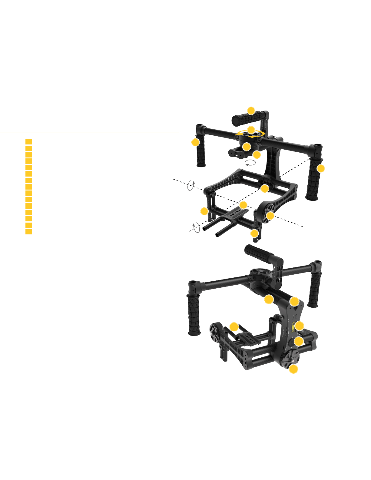
1 Top handle
2 Lock’n’Load connector
3 Pan motor
4 Side handles
5 Pan axis adjustment
6 Roll axis adjustment
7 Camera tray / slider / tilt axis front-to-back adjustment
8 Tilt motor
9 Tilt axis Center of Gravity adjustment
10 BeSteady Li-Ion battery compartment hatch
11 BeSteady Li-Ion battery compartment
12 Built-in OLED screen
13 Screen control keyboard
14 Roll motor
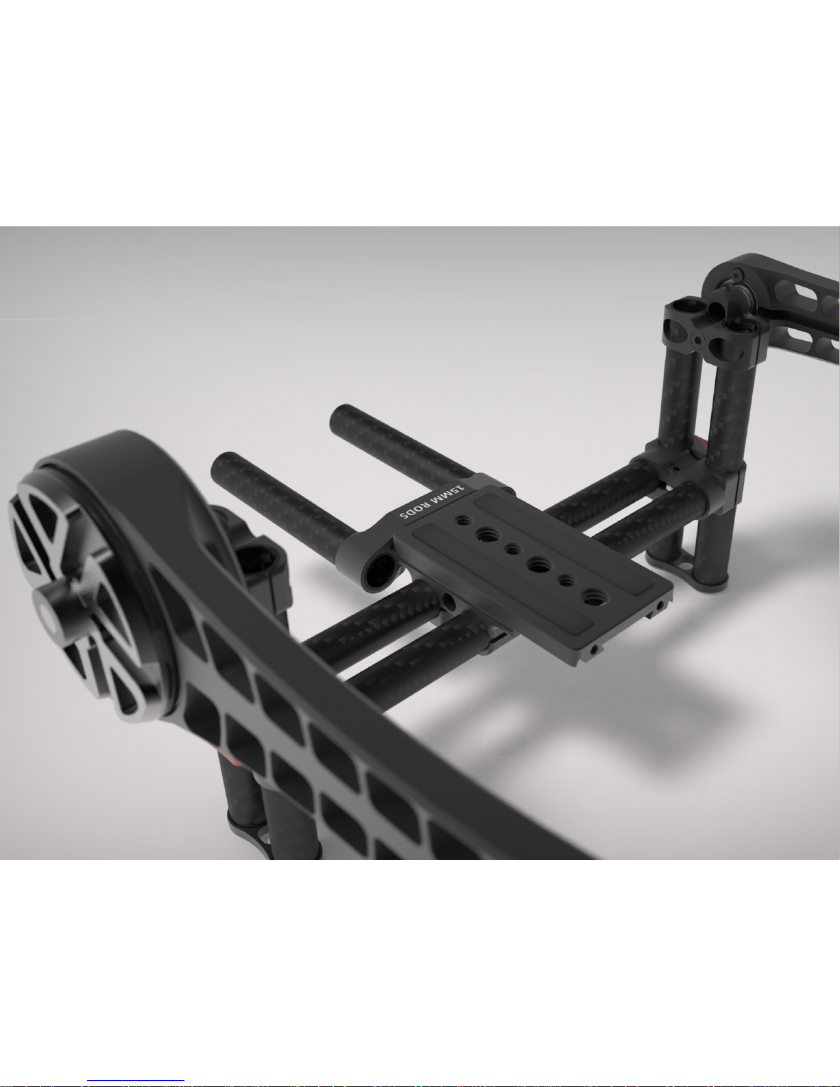
15 15 mm Rods Adapter (optional)
7
Page 8

GETTING STARTED
Before you start Charging the batteries
Do NOT connect anything to the DC OUT port! There is a safety sticker on the port. This
port is designed to power up external high-current devices and dedicated cables are to
be used with this port. Using this port incorrectly will cause damage to your gimbal that is
not covered by warranty.
Do NOT attempt to calibrate the accelerometer unless it is absolutely necessary or
indicated by a BeSteadty technician.
Always check your Lock’n’Load connection to the handheld! The connector should be
fully engaged and should ‚click’ everytime it is attached. Not checking that may cause the
Lock’n’Load to disconnect on its own during work and result in the gimbal falling to the
ground.
Always calibrate your gyro if the gimbal changes its location due to long travel. Bad
gyro calibration usually causes horizon drift or other unwanted behaviour. Gyro calibration
takes only few seconds to complete and only requries the gimbal not to move at all.
Do NOT attempt to charge two batteries at once (1x large battery and 1x small battery)!
Such attempt will damage the charger and/or both batteries.
Do NOT disconnect the small adapter cable from your Intelligent Charger. This cable is
essential for proper battery charging and is designed to work with custom BeSteady Large
Batteries. Connecting the battery directly to the charger without this cable will cause short
circuit and damage the battery or/and the charger.
Do NOT perform 360 degree rotation on the roll and tilt axis of the BeSteady FOUR too
many times as it will result in cable tension and may damage the primary cabling causing
a major malfunction.
Remember about the thresholds of the power output on both auxillary power plug on
the BeSteady FOUR camera tray and the DC OUT socket on the vertical arm. Both power
exits are part of the same circuit and the summarized power output cannot exceed:
3A when using small BeSteady batteries
5A when using large BeSteady battery
Always check if your charger is properly set for the battery you are intending to charge.
make sure to have the + (RED) and - (BLACK) cables properly connected!
use the round connector for the large battery and the rectangle connector for the
small battery
use the correct balancer port for every battery
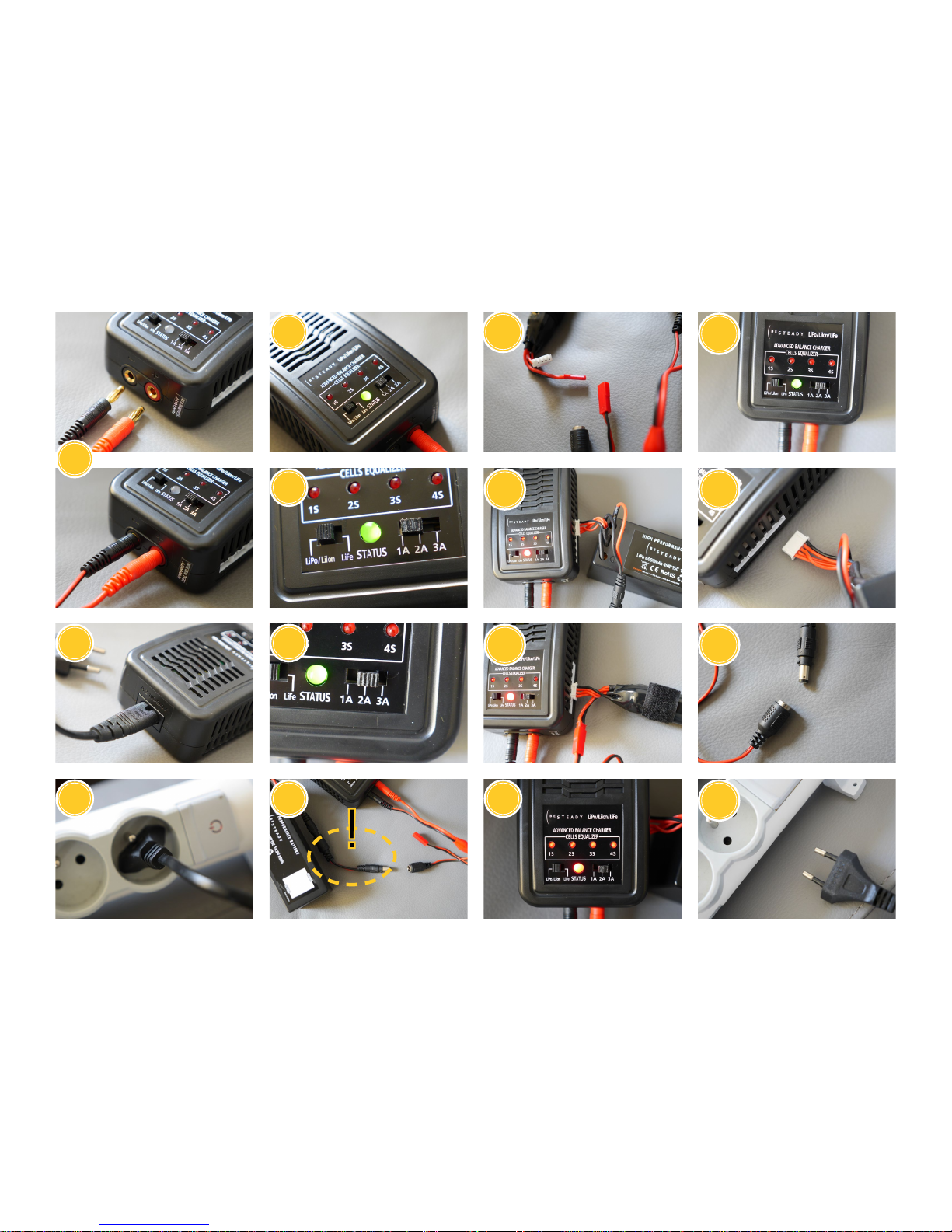
follow the correct actions order when attempting to charge a battery, as pictured on
the opposite page:
1. Connect the RED and BLACK power leads correctly.
2. Connect the AC power cable to the charger.
3. Insert the AC power cable into the wall socket.
4. All LEDs will light for 1 second and the charge status LED will ash green, which
indicates the charger is ready to charge.
5. Select the correct battery type on the charger. For all BeSteady batteries it is
LiPo/LiIon.
6. Select the recommended charging current: 2A for small BeSteady batteries, 3A
for large.
7. Connect the battery - use the black round connector (with the charger adapter
cable!) for the large battery (7a) and the red rectangle connector for the small
battery (7b).
8. Connect the battery balance lead to the correct balance socket on the side of the
charger - 4S for the large battery (8a), 3S for the small battery (8b). The charger
will automatically start charging.
9. The charge status LED and the cell status LED will light constant red. The cell 1-4
LED’s will glow continuously indicating the number of cells of the battery pack
currently being charged.
10. When the battery is fully charged, the “STATUS” LED will glow constant green.
11. Unplug the battery from the balance port.
12. Unplug the charge lead. The battery is ready for use in your BeSteady FOUR.
13. Unplug the charger from the wall socket if you are not going to use it further.
8
Page 9
1
2
3
4
5
6
9
7a
7b
10
11
12
13
8a
8b
9
Page 10
GETTING STARTED
WARNING: DO NOT use both types of batteries at once! Always use EITHER small batteries
OR large battery to power up your BeSteady FOUR!
BeSteady FOUR can be powered from either two small Li-Ion batteries tted inside the
dedicated compartment or from one large Li-Po battery placed on the special Battery
Mount Set for your handheld module. The small battery setup is intended to be used with
lightweight, low-power-consumption setups and adds compactness to the whole rig. If
you wish to power up external devices from the gimbal with small batteries, the power
consumption should not exceed 3A. The large battery power source is intended to be used
with cine setups consisting of several additional equipment such as follow focus systems,
wireless HD transmission adapters and high-current production cameras - everything can
be powered straight from the gimbal power source using auxillary Traxxas socket on the
camera tray and the DC OUT socket on the vertical arm - in case of the large battery it is
recommended not to exceed 5A power output.
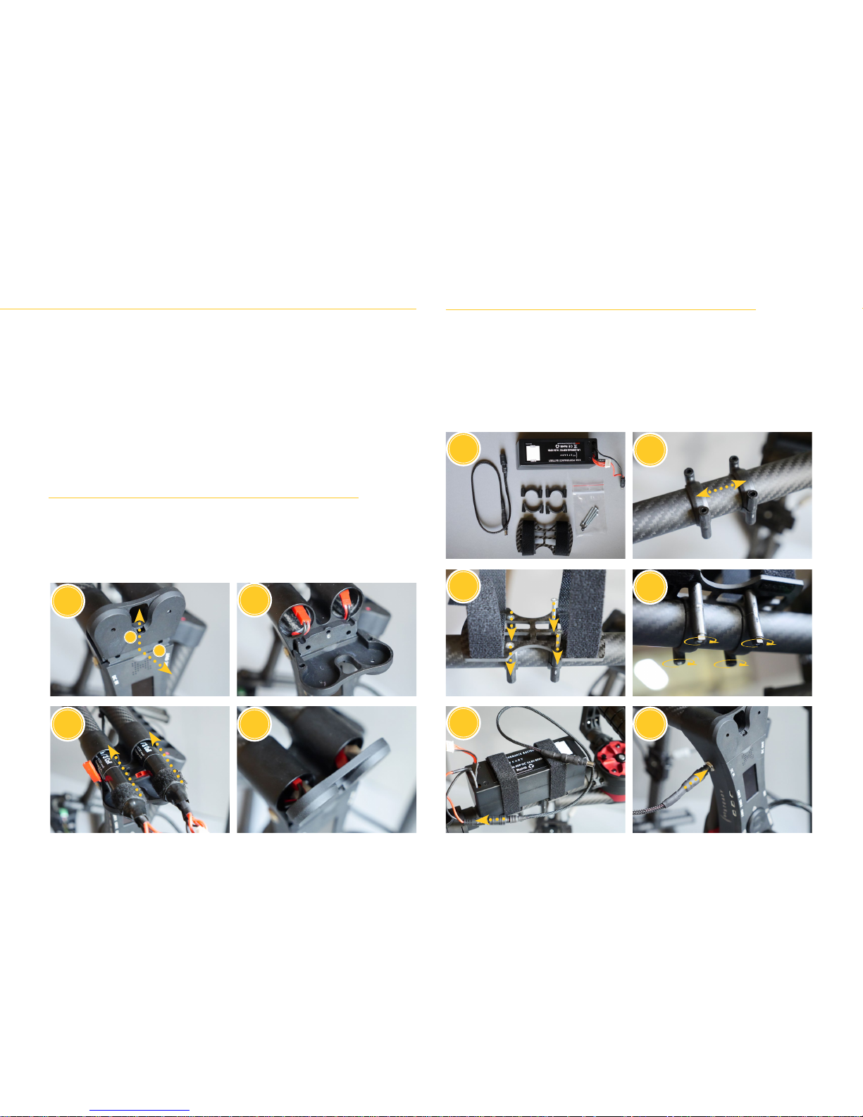
1. The small battery compartment hatch is located just above the OLED screen and the
speaker. Pull the hatch up and back to fully open the batteries compartment.
2. The are two JST battery connectors inside.
3. Insert the two small BeSteady Li-Ion batteries fully into their tubes.
4. Make sure that the gimbal is switched off and properly connect the batteries (pay
attention to the socket shapes!), hide the cables inside the tubes and close the
compartment hatch - it should click.
1. The large Li-Ion battery is to be used with the Battery Mount Set. The set consists of:
1x connection cable, 4x mount half-rings, 4x screws with nuts, 1x carbon plate with
velcro straps. The large battery itself has soft velctro straps for better attachment.
2. Place the mount rings on your handheld XL in a preferred spot and distance them to
t the holes of the battery plate.
3. Place the carbon plate on top of the mounts and use the screws to secure its position.
4. Use the nuts on the screws from below to tighten the mounts together.
5. Place the battery on the velcro spots and use the velcro straps to wrap it around and
secure it. Connect the main cable to the battery power lead.
6. Make sure that the gimbal is switched off and connect the cable to the DC IN socket.
Connecting the batteries
1
1
2
5
3
1
3
2
6
4
2
4
Option 1: Small Li-Ion batteries (2x)
Option 2: Large Li-Po battery (1x)
10
Page 11

Batteries maintenance
BATTERIES AND CHARGER
WARNING: You must read these safety instructions and warnings carefully before charging
or using your batteries. BeSteady small Li-Ion batteries require less care and are less
dangerous but failure to exercise caution while using BeSteady large Li-Po batteries and
comply with the following warnings could result in battery malfunction, electrical issues,
excessive heat, re, or injury and property damage. Apply the guidelines below to all kinds
of BeSteady batteries for maximum safety.
GENERAL GUIDELINES AND WARNINGS
Stop using or charging the battery immediately if the battery becomes or appears
damaged, starts to balloon or swell, leaks, becomes deformed or gives off an
odor, exceeds a temperature of 71ºC (160ºF), or if anything else abnormal occurs.
Disconnect the battery and observe in a safe area outside of any building or vehicle
for at least 45 minutes, as a damaged battery can experience a delayed chemical
reaction that could possibly result in re.
Never disassemble, modify, puncture, shock, drop, crash and/or short circuit the
battery. Leakage, smoke emission, ignition, explosion or re can occur, which may
result in personal injury or property damage.
Never charge the battery while installed on BeSteady or other equipment or while
inside a vehicle.
Always use a dedicated LiPo/LiIon charger only. Do not use a Nickel-cadmium (NiCd)
or Nickel-metal hydride (NiMh) charger, even though these chargers may appear
similar to a LiPo/LiIon charger. Failure to do so may cause a re, which may result in
personal injury and/or property damage.
Always ensure that the proper battery type and charging amperage is selected on
your charger for every battery. Failure to properly set these settings could result in re
or explosion of the battery.
Always check if the charger displays the correct number of cells of a given battery
after connection to the balancer port. Do not attempt to charge battery if the cell
count does not match the number of cells of a given battery.
DO NOT leave the battery and charger unattended during use.
Never drop charger or batteries.
Never connect more than one battery pack to the charger at a time.
Never attempt to charge “dead” or damaged batteries.
Never charge a battery if the cable has been pinched or shortened.
Never allow minors to charge or use battery packs without adult supervision.
Never charge near moisture, extreme temperatures, ammable or combustible
materials.
Never charge or store batteries in extremely hot or cold places (recommended
between 10º-26ºC/50º-80ºF), leave in a hot environment (inside an automobile in
hot weather), or leave in direct sunlight.
Never place or carry batteries in your pockets or clothing.
Always use dedicated BeSteady LiIon and LiPo batteries.
Always inspect the battery before charging.
Always connect the positive red lead (+) and negative black lead (-) terminals of the
battery to the charger terminals correctly.
Always disconnect the battery after charging, and let the charger cool between
charges.
If a battery will not be used for more than one week, it is recommended that the
battery is stored with a voltage of approximately 3.8V per cell. Do not store the
battery fully charged. Store the battery at room temperature in a cool or shaded area
(ideally between 10º-26ºC/50º-80ºF).
Batteries should be stored in a vented, re-resistant container. No more than
two batteries should be placed in a container to avoid chain reactions. Storage
temperatures should not fall below 0ºC/32ºF or above 54ºC/130ºF. Damaged
batteries are extremely sensitive to temperature uctuation and care should be taken
in their immediate disposal. High temperatures may cause re, even with undamaged
batteries.
NOTICE - HANDLING LIPOs: Mishandling of LiPo batteries can result in re. By handling,
charging or using the BeSteady LiPo batteries, you assume all risks associated with LiPo
batteries. If you are not prepared to accept complete liability for the purchase and/or use
of the batteries, you are advised to return them in new and unused condition to the place
of purchase immediately.
IMPORTANT NOTE - MINIMAL VOLTAGE: If you are using the battery to power or charge
an accessory used with the BeSteady, it is your responsibility to constantly monitor the
battery’s voltage through the use of a voltage checker. For optimal performance and
extended life, do not allow your battery voltage to drop below 3.4V. If the accessory
drains the battery below 3.0V per cell, it will damage the battery and render the battery
unusable. Never attempt to charge a battery that has individual cell voltages below 3.0V.
LIPO BATTERY DISPOSAL
LiPo batteries require special handling for safe disposal. The following steps must be taken
to avoid damage or injury to yourself, your property or anyone who comes in contact with
the battery. If the battery is undamaged but no longer useful:
1. Discharge the battery to a maximum of 1.0V per cell using a safe discharge method.
2. Leave the battery uncharged and retest the battery after 24 hours. If the battery is
over 1.0V per cell, repeat the procedure until the battery is 1.0V per cell or less.
3. Place electrical tape over each wire lead and tape the wire leads to opposite sides of
the battery.
4. Place battery in a sealed plastic bag and place plastic bag in a vented, resafe
container.
5. Use a re-safe container to deliver battery to a recycling center authorized for LiPo
batteries. Please note that not all batteryrecycling services include LiPo batteries. If
no LiPo recycling facility is available in your area, contact your state or local HAZMAT
agency for instructions.
If the battery is damaged:
1. If the battery or wiring is damaged, please contact your local HAZMAT facility for
instructions. Batteries must be rendered safe before being transported or recycled.
2. DO NOT transport or ship batteries which have more than 1.0V per cell charged OR
that show signs of damage without following the instructions given by the HAZMAT
agency.
11
Page 12
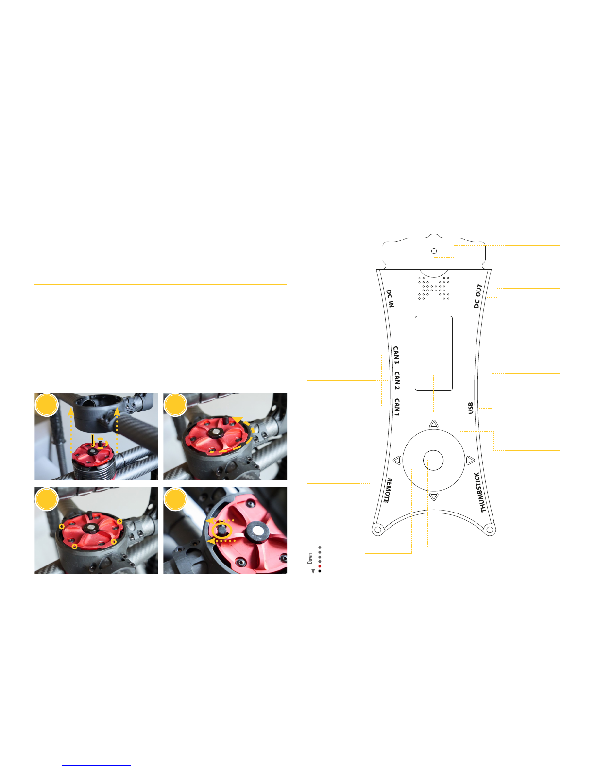
GETTING STARTED
Using the Lock’n’Load Connection ports
The custom Lock’n’Load system allows to quickly disconnect the gimbal from any adapter/
accessory attached to the top of the stabiliser (the pan motor). BeSteady FOUR comes
with a dedicated XL handheld module featuring Lock’n’Load connection. This proprietary
system is designed to work with various future accessories and make switching any
essential gear on set exceptionally easy without the use of any tools. Just insert, spin and
click!
USING THE XL HANDHELD WITH LOCK’N’LOAD FEATURE
The XL handheld is a basic tool to use the gimbal on the ground by a human operator. It is
necessary to make sure every time the FOUR is picked up that the Lock’n’Load connection
is fully engaged and secured. Failing to check the state of the connection may result in
sudden disconnection and render the gimbal fall on the ground.
1. Align the XL handheld with the Lock’n’Load male connector on the pan motor as
pictured. This is to make sure, that the gimbal always has the same starting position
when being launched in Follow Mode. Insert the XL handheld onto the Lock’n’Load
male section
2. Rotate the Lock’n’Load connector counter-clockwise so it secures the connection.
3. Make sure that the connector is fully rotated - the endpoints should be on the other
side of the rotation range.
4. Make sure that the locking lever is moved fully towards the outside of the ring.
DC IN socket
Main power-in socket for
external power source
such as BeSteady Large
Li-Po battery
CAN ports
Auxillary communication /
signal ports for future use.
These utilize a standard
miniUSB socket.
REMOTE socket
Remote control socket
for external signal
receivers. Used to
connect the Graupner
GR-16L receiver that
comes with the MZ-12
radio. DO NOT connect
the Thumbstick to this
port!
Built-in keyboard
Used for navigation
around the OnBoard
Manager
Control Button
Performs various actions
depending on the number of
consecutive clicks or after a long
click, congurable through the
OnBoard Manager and external
software.
THUMBSTICK socket
Used for connecting
analog BeSteady
Thumbstick.
Operates on a
different voltage
than the REMOTE
socket! DO NOT
connect radio
signal receivers
to this port!
USB port
Used to connect USB
cable for external
software conguration
and Service Mode
or 5V power input
from a computer to
power up the OnBoard
Manager for passive
conguration and
BlueTooth
OLED screen
Provides live
information and
displays the OnBoard
Manager menus and
options
Speaker
Emits voice messages
about gimbal status,
commands, menu
options, errors, etc.
DC OUT port
Used to power up
external devices
through dedicated
cables. Similar to the
auxillary Traxxas plug
on the camera tray.
DO NOT connect the
batteries or any other
power sources to this
port as it will damage
the main board!
1
3
2
4
Signal pin 4
Signal pin 3
Signal pin 2
Signal pin 1
Voltage (+)
Ground (-)
12
Page 13
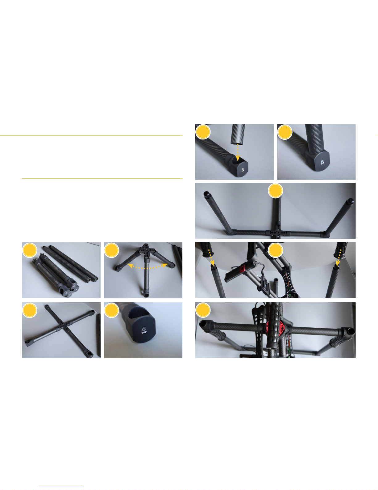
The XL stand is used for balancing, showcasing and storing the stabiliser. It is lightweight
and folds into a compact form for ease of transportation. The central part of the stand
features various holes and threads which allow it to be used with third-party camera
support equipment such as sleds, tripods, etc. The stand can hold the gimbal with the
handheld module in both underslung and inverted positions.
ASSEMBLING THE STAND
1. The stand comes in 3 parts: 1x main stand component and 2x carbon vertical tubes.
2. Unfold the main component as pictured.
3. Place the main component on a at, solid surface.
4. Make sure that the signs on the endpoints indicate the top direction correctly.
5. Insert the vertical carbon tubes in the two large holes on the opposite ends of the
stand (the other holes have smaller diameter and will not accomodate the tubes)
6. Make sure that the tubes sit tight in the holes.
7. The stand should look like on the picture.
8. Insert BeSteady FOUR with the handheld onto the caps on top of the tubes. Note, that
you can also insert the gimbal while inverted.
9. Make sure that the gimbal is fully engaged with the stand.
1
3
2 8
7
5
6
4
9
Using the XL stand
13
Page 14
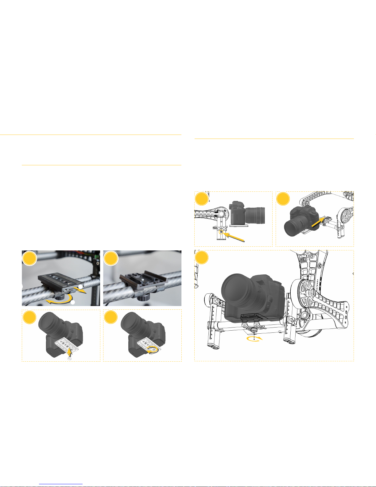
GETTING STARTED
Mounting the camera
BeSteady FOUR uses a quick release camera plate to quickly and easily attach and remove
your camera from the stabiliser. It is essential that you fully build your camera setup before
installing it onto the gimbal as it has direct impact on balancing.
ATTACHING THE PLATE TO THE CAMERA
The camera plate features two types of threads for mounting both DSLRs and production
camera alike. It is recommended to choose a thread hole as close to the assumed camera-
lens setup center of mass as possible.
1. To remove the camera plate from the tray, rotate the camera plate knob clockwise
until the camera plate slides off the mount. NOTE: turning the knob about half-turn
allows the camera plate to slide back and forth. Turning the knob about halfway the
range allows the whole mount to move left and right. This is essential to understand
when balancing the gimbal, as described in further sections of the Manual.
2. When the plate is removed, the mount looks as pictured. Notice how the slider edges
are positioned when attaching the camera plate back.
3. Place the camera plate under (or above in some camera models) your camera and
choose the thread you wish to use for attachment.
4. Tighten the camera screw well and make sure that the plate is aligned with lens axis.
Not securing the camera plate properly may result in unwanted camera movement
and loss of balance during gimbal operation.
INSERTING THE CAMERA ONTO THE STABILISER
1. Loosen the camera plate knob so the mount edges can be moved to align with the
camera plate sliders.
2. Slide the camera with the plate onto the mount and make sure that all surfaces are
correctly aligned and in the correct gaps.
3. When the plate is fully onto the mount, secure it with the knob. At this point you can
pre-balance the camera on tilt axis - try to position the plate in a spot that will allow
the camera to stay more or less in place by itself and not fall to either front or back.
3
1
2
1
3
4
2
2
1
14
Page 15
15
Page 16
Balancing the FOUR
B
alancing is a crucial aspect of proper gimbal operation. Good
balancing can provide the best possible performance while bad
balancing will leave room for many unwanted occurences such
as micro-jittering or low range of operational angles. It is important to
take some time to get used to how the balancing works. The Beast
requires no tools to balance properly and with some experience it
can be done in no time for cameras that are common for you. You
will notice that the more you work with a particular camera setup,
the more muscle memory you obtain and it takes much less time
to prepare the stabiliser when following a familiar set of actions.
UNDERSTANDING THE AXES
A three-axis stabiliser works on tilt, roll and pan axes. The best
practice is to balance tilt axis rst, followed by roll axis and
pan axis. Tilt axis takes the most time to balance as there are
two points that need to be taken: front-to-back balancing and
Center of Gravity balancing. Roll balance should always be
performed after tilt balance is complete. Pan balance should
be done last and requires proper tilt and roll balance.
The balancing should always be done on a complete camera setup that you intend to work with. Adding any additional gear or switching to very different lenses usually
requires new balancing. The gimbal always has some
spare power to overcome not-so-perfect balancing and
can take a moderate change in focal length while on a
set but generally it is recommended to check balancing
after evert gear change.
It is recommended not to tune and use the gimbal if
the balancing is not done correctly. Many user problems come from wrong balancing - that is why this
important step should never be ignored.
Page 17
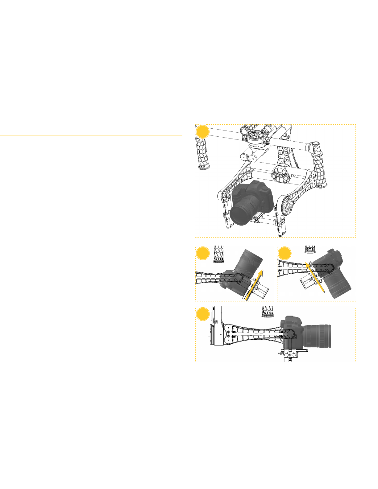
Tilt front-to-back balance is achieved when the camera remains leveled on its own when
in neutral position. It should not fall forward (lens heavy situation) or backward (body
heavy situation) unless pushed. This is the rst step to achieve tilt axis balance and is
achieved by operating the camera plate only.
FRONT-TO-BACK BALANCE
1. Make sure that the camera plate with your whole camera setup is properly installed
on the tray mount. Place the camera in its neutral, 0 degrees position as pictured.
2. If the camera falls to the back, it is body heavy. Loosen the main plate knob and move
the plate forward (towards the lens) to compensate the imbalance.
3. If the camera falls to the front, it is lens heavy. Move the plate backward (towards the
camera body) to compensate the imbalance.
4. Work your back and forth movement so that you nd the spot in which the camera
stays on its own in the neutral position and is not willing to fall forward or backward.
Once such position is achieved, the rst step of tilt axis balancing is complete.
Tilt front-to-back balance
1
2
4
3
17
Page 18
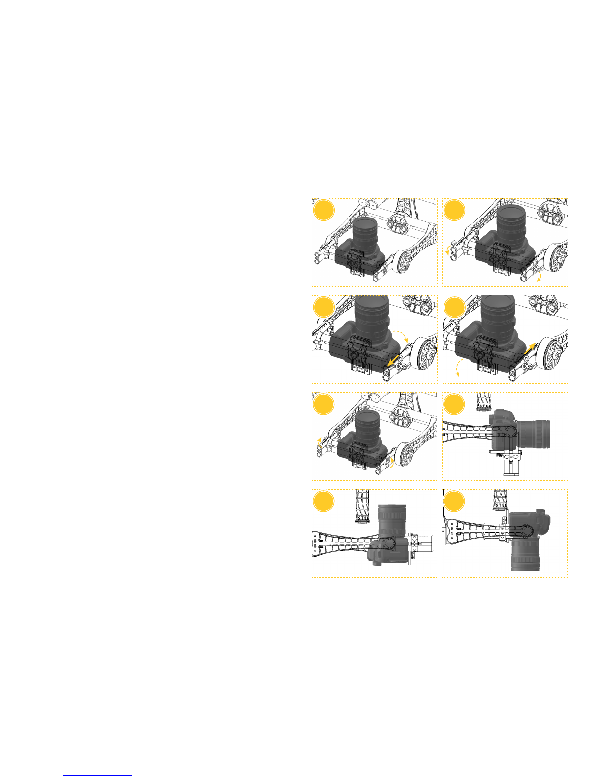
BALANCING THE FOUR
Tilt Center of Gravity balance
Once the tilt front-to-back balance is completely, you will most likely notice, that the
camera is only able to stay at neutral position but wishes to fall either forward or backward
when touched or pushed. This is because the Center of Gravity is not alligned with center
of mass of the camera-lens-camera tray block. To x that, the tray needs to be moved up
or down along the printed scale to nd this alignment.
CENTER OF GRAVITY BALANCE
1. Place your camera setup with lens facing 90 degrees to the top as pictured. Hold the
whole tray so it does not rotate on its own at this point.
2. Release the side clamps to unlock the camera tray so it can move along the tubes
with printed scale. Always use this scale to be sure that the left and the right sides
are on the same level.
3. Observe the camera. If it attempts to fall back, towards the roll motor - the center of
mass is too high. Move the whole tray down, towards the higher digits on the printed
scale. Remember to move both sides of the tray simultaneously and check if they are
on the same level.
4. If the camera attempts to fall to the front - the center of mass is too low. Move the
whole tray up, towards the lower digits on the scale while maintaining simultaneous
movement on both sides.
5. When you nd a position when the camera stays on its own with the lens facing to
the top, you may close the side clamps to secure it. The tilt balance may be complete
at this point but it has to be conrmed but checking various camera positions.
6. Check if the camera stays on neutral position and does not try to move when touched
or pushed.
7. Check the 90 degree top position as pictured. The camera should also stay on all
angles in between.
8. Check the 90 degree bottom position as pictured. If the camera stays at this position
and at all angles in between, the tilt axis balance is complete.
1
5
3
4
7 8
2
6
18
Page 19
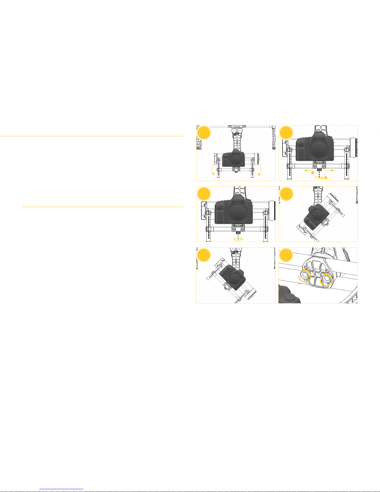
After the tilt balance is complete, roll balance can be performed. The are two ways to
achieve good roll balance: moving the camera plate left and right and adjusting the roll
bar through roll adjustment thumbscrews.
NOTE: Extremely heavy setups are likely to be not perfectly balancable on roll axis. Such
setup will be attempting to return to neutral roll position when leaned left or right on roll
axis. That is normal and is happening due to the fact that some setups are beyond the
adjustment ranges even though the weight is within the supported payload. In such cases
the roll operating angles will most likely be limited and it may be easier to push the gimbal
out of position on roll axis.
ROLL BALANCE
1. Position the camera in neutral position and check which side the camera tray wishes
to fall to on the roll axis.
2. Loosen the camera plate knob about halfway so you can move the whole camera left
and right. Be careful not to move the plate front to back as it may result in loosing the
tilt axis balance point. Move the camera to side opposite to the side where the whole
block wishes to fall to to compensate the roll imbalance.
3. Try to nd a spot where you feel that camera stays on neutral roll position and does
not lean to any side. Tighten the knob back afterwards.
4. With such spot found, check if the camera also stays on various roll angles - neutral,
45 degrees and 90 degrees, both left....
5. ...and right sides.
6. (Optional) In case the range that you are allowed to move the camera plate left
and right in is not sufcient to achieve a good roll balance due to your camera size
or other reasons, you can use the two roll bar adjustment screws on the inner side
of the roll motors. Loosen those screws to perform a macro roll adjustment and
move the whole roll bar left and right. NOTE: Be sure to support the whole weight
that you have on your stabiliser from the bottom by hand when loosening the
main roll bar adjustment. Large forces are always working on that connector and
loosening it weakens the gimbal structure. When balancing very heavy setups it
is recommended to have another person to assist in supporting the payload while
adjusting roll axis through this option.
The roll balance is complete, when the camera stays on its own on various roll angles. At
this point it should also stay on various combinations of tilt and roll angles given that the
tilt balancing was nished properly as described in the previous section.
Roll balance
1
1
2
5
3
4
2
6
19
Page 20
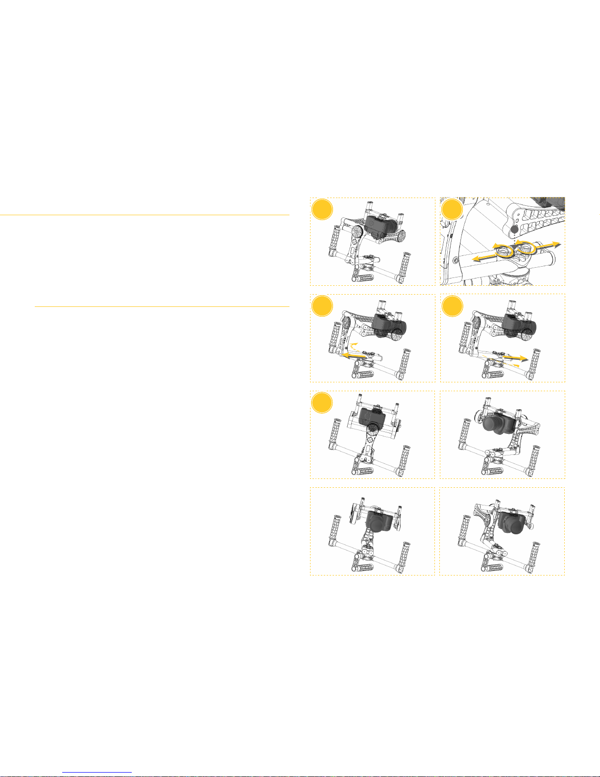
BALANCING THE FOUR
Pan balance
With both tilt and roll axes balance, the balancing can be completed with pan axis. The
pan axis balance is probably the most difcult to understand and visualize. The pan axis
is balanced when the whole weight beneath the pan motor is able to stay in position on
various angles. To check that and adjust accordingly, some force has to be applied on the
pan axis to see where the whole mass wishes to lean. To achieve that, the pan axis has to
be tilted during checking and adjusting - when it is leveled, no force will work on the pan
axis to indicate the imbalance.
PAN BALANCE
1. Position the stabiliser upside down (inverted) on a at, solid surface as pictured.
2. The pan axis adjustment is located on the opposite side of the pan motor and is
secured with two adjustment thumbscrews (similar to those found on the roll
adjustment). Loosen these screws to move the whole pan arm back and forth. You
may need to push the pan axis towards the pan motor a bit with one hand to ease
the movement (X).
3. Observe the camera. If the gimbal falls towards the upper tilted side - the block is
front heavy and you need to move the pan bar back.
4. If the gimbal falls towards the lower tilted side - the block is back heavy you need to
move the pan bar to the front.
5. The goal is to nd a spot where the pan bar stays by itself on any given position
around the 360 degree range. Check various positions to see if it is achievable.
The pan axis balance is complete when the gimbal is able to stay in position at any given
angle. NOTE: Extremely heavy setups may not be fully balancable on pan axis. In such case
it is best to try to achieve balance when the pan axis is aligned with the handheld line an
tried to return to this line from other positions.
The whole balancing process is now complete. You may now return the gimbal to the
normal underslung position, put it back on the stand and conrm proper balancing by
checking various camera positions.
1
5
3
4
2
X
20
Page 21
21
Page 22
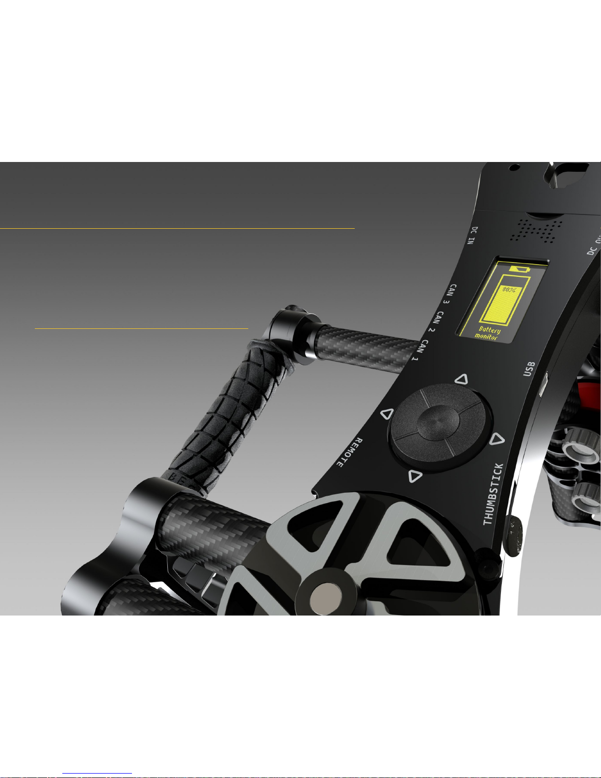
The OnBoard Manager
B
eSteady FOUR introduces a completely new way of how the gimbal can be congured - the OnBoard
Manager. Thanks to this ultimate feature the stabiliser does not require any external devices or
software to be congured to work. Everything can be done through the built-in command
center, from axis stiffness to Follow Mode settings. The voice information system provides live
commands acknowledgements, error statuses and other crucial information. The sharp OLED
screen is highly readable in all conditions and along with the easy-to-use control keyboard
makes working with The Beast an enjoyable and intuitive experience.
INTERNAL CONFIGURATION LIMITATIONS
The OnBoard Manager allows access to most stabililser functions. However, advanced and expert functions require using external, dedicated software. The
more advanced functions include conguring remote control functions other
than the default MZ-12 setup, calibrating accelerometer, etc. The external
software also serves as a maintenance front-end and allows troubleshooting in cases the OnBoard Manager does not provide enough information or is not accessible.
In most cases, the OnBoard Manager is more than enough to
professionally work with BeSteady FOUR. The workow with
a stabiliser of this kind on a set has never been so easy!
Page 23
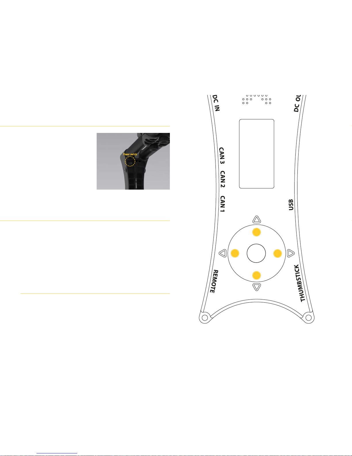
NOTE: Always initiate the stabiliser with a
balanced camera setup. The stabiliser does
not operate without the camera attached
is not supposed to be launch unarmed.
BeSteady FOUR is precongured to work
straight from the box with a mediumweight camera. After properly connecting
the power source and switching the power
switch the gimbal will perform a series of
self-tests, which last for a few seconds and
will start with the Summary Screen on the
OLED display.
NOTE: The launch sequence may take longer if the „Skip Gyro calibration at startup” option
is turned off. This option is turned on by default.
1. UP - navigate to the upper position in the menu / raise setting value
2. LEFT - navigate to the previous menu level / save chosen setting
3. RIGHT - navigate to the next menu level / switch option / perform action
4. DOWN - navigate to the lower position in the menu / lower setting value
USB CABLE PLUG IN while holding DOWN - enter Service Mode / Mass Storage
Mode (requires USB connection)
WARNING: The navigation buttons are automatically inverted when the gimbal detects
Inverted Mode. This is to not confuse the operator when the vertical arm is inverted and
the OLED screen is positioned under the keyboard.
SHORTCUT KEYS
NOTE: these shortcuts will only work in Summary and Battery Monitor screens
HOLD RIGHT for 3 seconds - locks / unlocks the keyboard. This shortcut can be enabled /
disabled in the Screen menu
HOLD DOWN for 3 seconds - switches between Summary and Battery Monitor screens
Launching The Beast
Keyboard navigation
1
2
3
4
23
Page 24
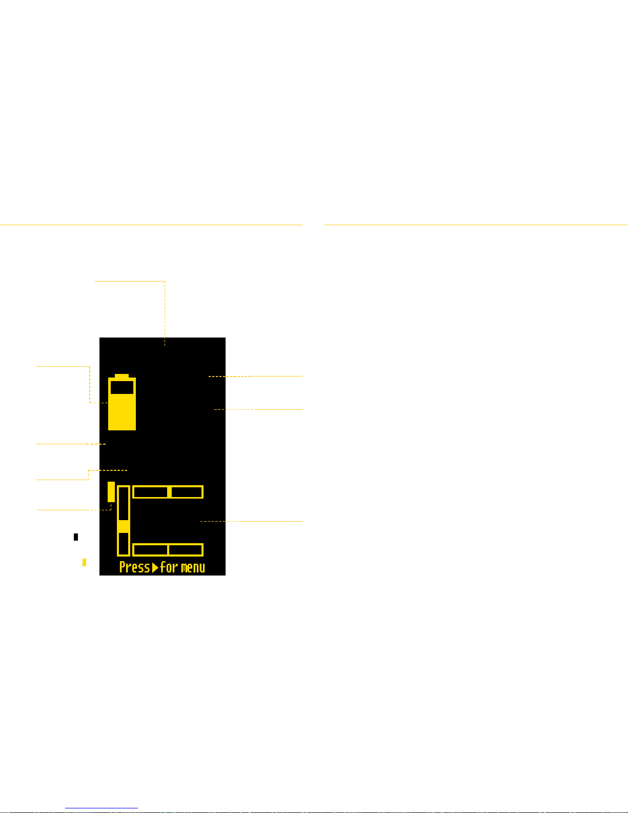
THE ONBOARD MANAGER
The Summary Screen
This screen is visible after BeSteady FOUR successfully initiates after a series of self-tests.
It provides general information on current status of the stabiliser and camera position.
Proles provides access to proles choice. BeSteady FOUR supports up to 5 various
proles. Proles are stored in .bsp les on the memory card and can be
accessed and shared using the Service Mode. NOTE: DO NOT remove or
change the defaults.bsp le!
Autotune enters Autotune function. The gimbal will perform a series of actions to
provide optimal performance for the current camera setup. Occasional jitter
and vibrations may occur during the procedure. The procedure takes around
2 minutes. Autotune is a good way to start your tuning, however usually the
best results require additional settings.
Performance main menu for ne-tuning gimbal performance. Primary functions and motor
powers are set here. Use the LEFT arrow to save a given setting value. Try
to set the motor powers as high as possible without the vibrations kicking in.
If the vibrations start, lower the strength by 5-10% and keep it there. Pay
attention to which axis produces the most jitter and start adjusting there. You
may need to readjust the power settings after a change in the camera setup.
Calibrate gyro - calibrates the gyro. The gimbal has to remain completely
stationary during gyro calibration.
Tilt Strength - sets tilt motor strength
Roll Strength - sets roll motor strength
Pan Strength - sets pan motor strength
Filter Strength - sets lter strength. Use for eliminating micro-vibrations.
The default setting is 33%
Skip calibration O/F - toggles the initial gyro calibration. This option is ON
by default
Follow main menu for tuning the Follow Mode. The responsiveness settings tell a
given axis how fast it should match the operators position after an operator
performs a movement.
Follow mode - engage or disengage Follow Mode on an axis
Follow tilt - engages Follow Mode on tilt axis
Follow roll - engages Follow Mode on roll axis (NOTE: this will also
enable Follow Mode on tilt axis as these two axes are paired together
in the Follow Mode code
Follow pan - engages Follow Mode on pan axis
Xtended st. - switches back to Xtended Stabilisation (clean) mode
Tilt Follow - sets the responsiveness of Follow Mode on tilt axis.
Roll Follow - sets the responsiveness of Follow Mode on tilt axis
Pan Follow - sets the responsiveness of Follow Mode on tilt axis
Foll. Deadband - sets the safe zone, where the Follow Mode does not
engage
Foll. Expo rate - sets the acceleration of Follow Mode. Higher settings will
render the Follow Mode more smooth, lower settings will render it more
linear.
Up Time
Shows the running time from
the last launch.
Mode
Shows the mode the
gimbal is currently
operating in.
Battery status
Shows the current
charge level of the
battery.
Prole
Shows the current
prole.
Axis mode indicator
T - tilt axis
P - pan axis
R - roll axis
A yellow letter (T)
indicates that the axis
is not in Follow Mode
A black letter with (T)
yellow background
indicates that the axis
is in Follow Mode.
Current voltage
Shows the current
battery voltage.
Time left
Shows approximate
operating time
left on the
current battery.
The estimation
becomes more
precise after time.
Axis position indicators
Shows live deviation in
degrees of tilt, pan and roll
axes from the calibrated
zero point / horison level.
Up Time 00:00:28
11.79V
Time Left
Mode:Underslung
Profile 1
-4.2
2.1
P
R
T
0.0
323 min
Menu walkthrough
24
Page 25

Control menu for settings related to the remote control devices and the CONTROL
button.
Control button - sets actions to consecutive clicks of the button
1-5 click - sets action to 1, 2, 3, 4 or 5 CONTROL button clicks
Long click - sets action to a long CONTROL button click
Filter - sets lter for remote control signal input. Larger lter setting renders
the remote control less responsive.
Deadband - sets a safe zone where operating the remote control servos /
joysticks does not affect the gimbal
Expo - sets the smoothness of remote controlled movement. Low
expo sets provide more linear movement, high expo provide smoother
movement with easing-in and easing-out.
Tilt/Pan Speed - sets the speed of remote control for tilt and pan axes.
Default RCU - sets the correct pin settings for the dedicated Graupner
MZ-12 Remote Control Unit. Use before your rst MZ-12 run.
Sound menu for setting the sound / voice options
Commands O/F - toggles voice command conrmations
Errors O/F - toggles voice error information
Volume - sets voice volume
Screen menu for OLED screen settings
Brightness - sets OLED screen brightness
Lock O/F - enables the shortcut to lock the keyboard (RIGHT keyboard
shortcut).
Details menu for various details about the unit
Details screen - displays information about the current rmware on the
unit as well as QR code for accessing BeSteady website
Battery monitor - displays large live battery status monitor
Save Prole - saves the current prole to .bsp (BeSteady Prole) le on
the internal microSD card
Save All Prof. - saves all 5 proles to .bsp les on the internal microSD card
Load Prole - loads and overwrites the current prole from a .bsp le with
the same prole name (if existent on the microSD card)
Factory default - loads factory default settings. WARNING: do not use this
option unless absolutely necessary or instructed by a technician. These
settings are stored in the default.bsp le - do NOT modify or delete this
le!
Service Mode
Using USB / BlueTooth connection
Service Mode is used for rmware updates as well as voice banks swapping.
To enter this mode it is required to hold the DOWN button while inserting the USB cable
into the USB port. The gimbal will be detected as a mass storage device in the computer
system and les saved on the internal microSD card will become accessible.
To congure the BeSteady FOUR through the external software either USB or BlueTooth
connection is required.
NOTE: The BlueTooth module requires powering up either from the USB port or from the
BeSteady battery power source.
The dedicated software - the BeSteady Manager - uses both connection methods. The
BeSteady Manager software has a dedicated Manual. For details, visit www.besteady.eu
USB connection
1. The unit is equipped with a miniUSB port for connecting to a computer.
2. Connect the USB cable to your computers USB port.
3. Connect the miniUSB plug to the USB port on the BeSteady FOUR
4. Launch the BeSteady Manager and choose the proper port for connection
5. The Manager will initiate with the main tab.
BlueTooth connection
1. BeSteady FOUR needs to be powered up either from USB port or from the BeSteady
battery for the BlueTooth connection to be estabilished.
2. When BlueTooth module has power, search for the device in your Windows / Mac
BlueTooth environment. The device name may vary depending on the rmware
version.
3. When found, click the Pairing option.
4. A verication code will appear. Click OK when you are sure that you are connecting
to your unit.
5. The pairing should success after a few seconds.
6. Launch the BeSteady Manager and choose the proper port to estabilish connection.
25
Page 26
OPERATING MODES
Operating modes
T
here are various operating modes that suit various shooting situations. In general two main areas of operating a gimbal can be highlighted: single operator and
multi operators. Single operators usually use the intuitive Follow Mode, where the gimbal follows operators movements and in such case a second person is either not necessary or provides framing assistance via a remote control device only. Multi, more professional operator mode utilizes at least two users to achieve
desired framing - one person holds the gimbal and controls its general position and direction its facing while the second person is responsible for detailed framing with,
for example, third person pulling focus. It is essential to know every modes limitations and choose the right conguration for every job.
26
Page 27

The most popular operating mode - the Follow Mode - allows a single person to walk and
shoot on his/her own. The purpose of the Follow Mode is to imitate operator’s movements
and eliminate the need of using an external Remote Control Unit for camera movement
control. The Follow Mode is fully congurable within the OnBoard Manager in the Follow
menu.
An operator can enable the follow function to either 1, 2 or all 3 axes. It is important to
remember that while the tilt and pan axes can be engaged separately, the roll axis is
always paired to the tilt axis and cannot operate on its own - it always works with the tilt
axis following as well.
The Follow Mode can be congured to be either very linear, „robotic” or smooth, cinematiclike. BeSteady FOUR, thanks to very sophisticated movement control technology, makes
the Follow Mode very smooth, natural and responsive at the same time. Feel free to
experiment with Follow speed and expo settings on every axis to achieve the most
satisfying results.
The Xtended Stabilisation is a clean stabilisation mode where the camera remains leveled
independently of the rest of the gimbal. This mode is designed to work with an external
control device such as an RCU or the Thumbstick as the rst operator (gimbal holder) will
not be able to control the framing and the camera will always point in one direction unless
controlled by an external signal. Xtended Stabilisation also allows the gimbal to go to the
Slim Side Mode, a „briefcase” position for low shots.
Follow Mode
Xtended Stabilisation
Slim Side Mode
The Slim Side Mode is an extension of the Xtended Stabilisation, where the gimbal is
positioned vertically („briefcased”) by the operator who is holding the device by one of
the side handles. This allows for low pass shots or when shooting in narrow corridors /
doorways or when the usage of only one hand is required (for example when riding a
bike).
TIP: When in Slim Side Mode, the Follow Mode can be engaged either by using the
OnBoard Manager menu, the Control Button or the Command Channel on the RCU. In such
case the original Roll axis will become the Pan axis due to the gimbal position to allow
the operator to intuitively follow as if the gimbal would be following in normal position.
27
Page 28

OPERATING MODES
Remote Control
Remote Control comes in where a single person is not enough to obtain proper framing
while lming. The Remote Control in general denes every external equipment used
to control the position of the camera on the gimbal - be it cabled or radio / wireless
equipment. The gimbal can be remotely controled in all of the previously described modes
- that makes the Remote Control more of a complimentary mode than a stand alone
feature.
There are two connection ports on the BeSteady FOUR for remote control devices. The
REMOTE port is used to connect radio signal receivers, such as the dedicated Graupner
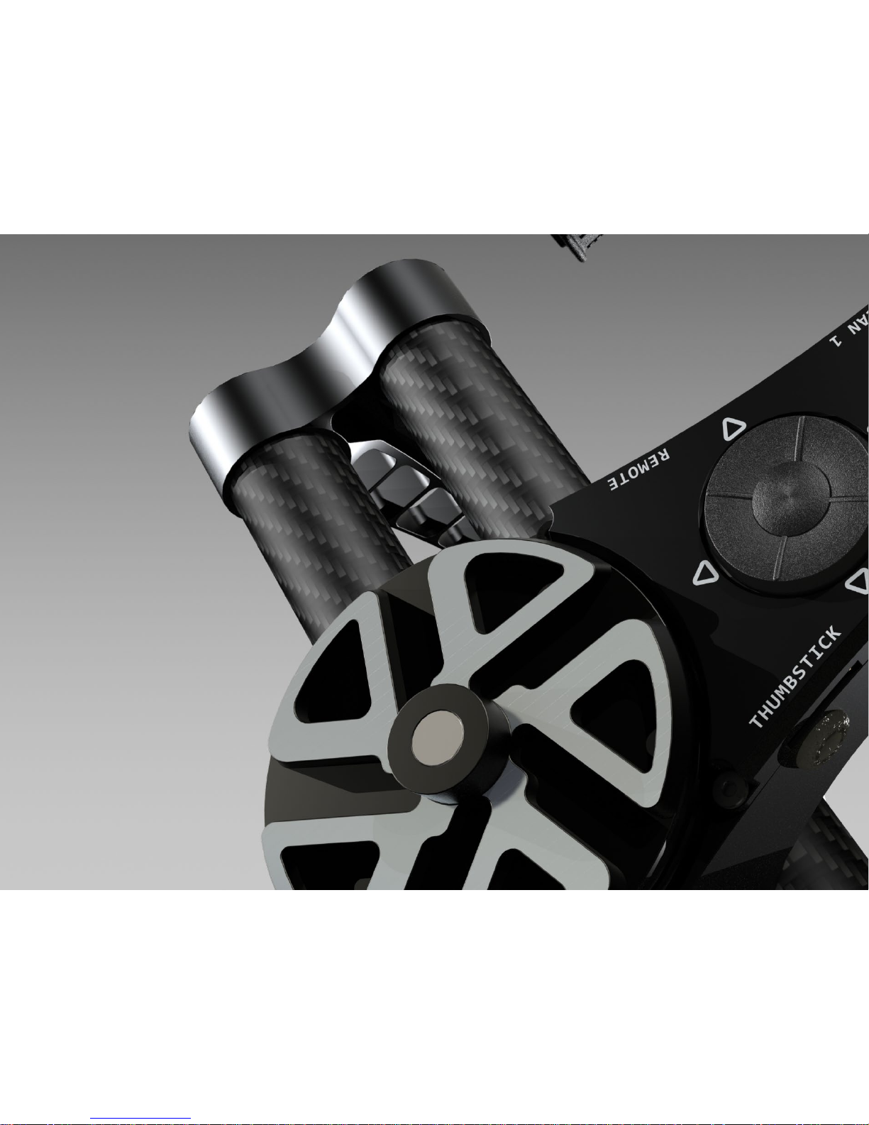
GR-16L receiver from the MZ-12 radio set. The THUMBSTICK port is used to connect
analog joystick controllers such as the dedicated BeSteady Thumbstick.
NOTE: Do not mix the ports! Do not connect a radio receiver to the THUMBSTICK port and
an analog joystick to the REMOTE port!
The Thumbstick adds additional framing options for a single operator and is usually
mounted on the handheld module close to operators thumb nger.
An external radio is used in more advanced setups were external framing control is
necessary.
The Frame Invert is an additional camera mounting option which allows to hang the
camera under the camera tray rather than place the camera on it. Several cameras have
top mounting holes (for instance RED cameras, BlackMagic Design cameras) which allow
them to be used in such conguration. Hanging the camera enables a better range of
balance, especially for very heavy and bulky cameras such as the RED Epic. Similarly to
the Inverted Mode, BeSteady FOUR automatically detects the camera tray position during
startup for proper operation. It is recommended to use this mouting option for massive
setups which usually have a low positioned center of mass.
NOTE: the Frame Invert can work in every operating mode.
Frame Invert
The Inverted Mode allows the unit to work upside down enabling the operator to have the
camera at a more comfortable eye-level.
The Inverted Mode is engaged automatically depending on the position the gimbal is
launched in. It is important to remember that it is not possible to toggle the Inverted Mode
while the gimbal is running. The keyboard controls and the OLED screen are inverted as
well when the Inverted Mode is detected.
Inverted Mode
28
Page 29
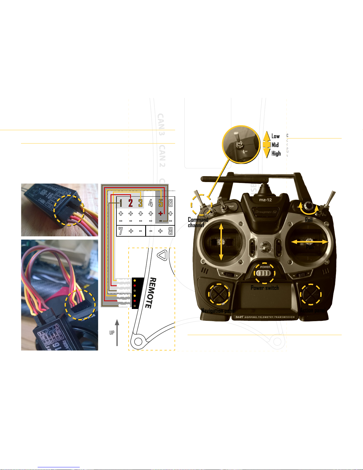
GR-16L receiver setup
The RC signal cable comes pre-connected to your Graupner GR-16L receiver for default
conguration of the MZ-12 Remote Control Unit (RCU). It is essential to keep this cable
connected that way as changing the pinout conguration will result in change of Remote
Control operation. If you are intending to change your RCU or cable conguration, be
completely sure that you have the knowledge about setting up custom RC congs.
IMPORTANT: Make sure that the BeSteady FOUR has Default RCU conguration saved. Use
the Control -> Default RCU option in the OnBoard Manager to save correct MZ-12 settings.
WARNING
Always connect the GR-16L receiver while the BeSteady is NOT powered up from the
battery or from USB port! Do NOT connect the GR-16L or any other RCU receiver to the
Thumbstick port!
Default Graupner MZ-12 RCU setup
Command channel
Command channel switch positions
can perform the same tasks as those
programmable for the Control button.
Use the external BeSteady Manager
software to congure the RCU Command
Channel.
Tilt
Command
channel
Pan
Power switch
Navigation panel
Action panel
Roll
Low
Mid
High
Signal pin 4
Signal pin 3
Signal pin 2
Signal pin 1
Voltage (+)
Ground (-)
29
Page 30
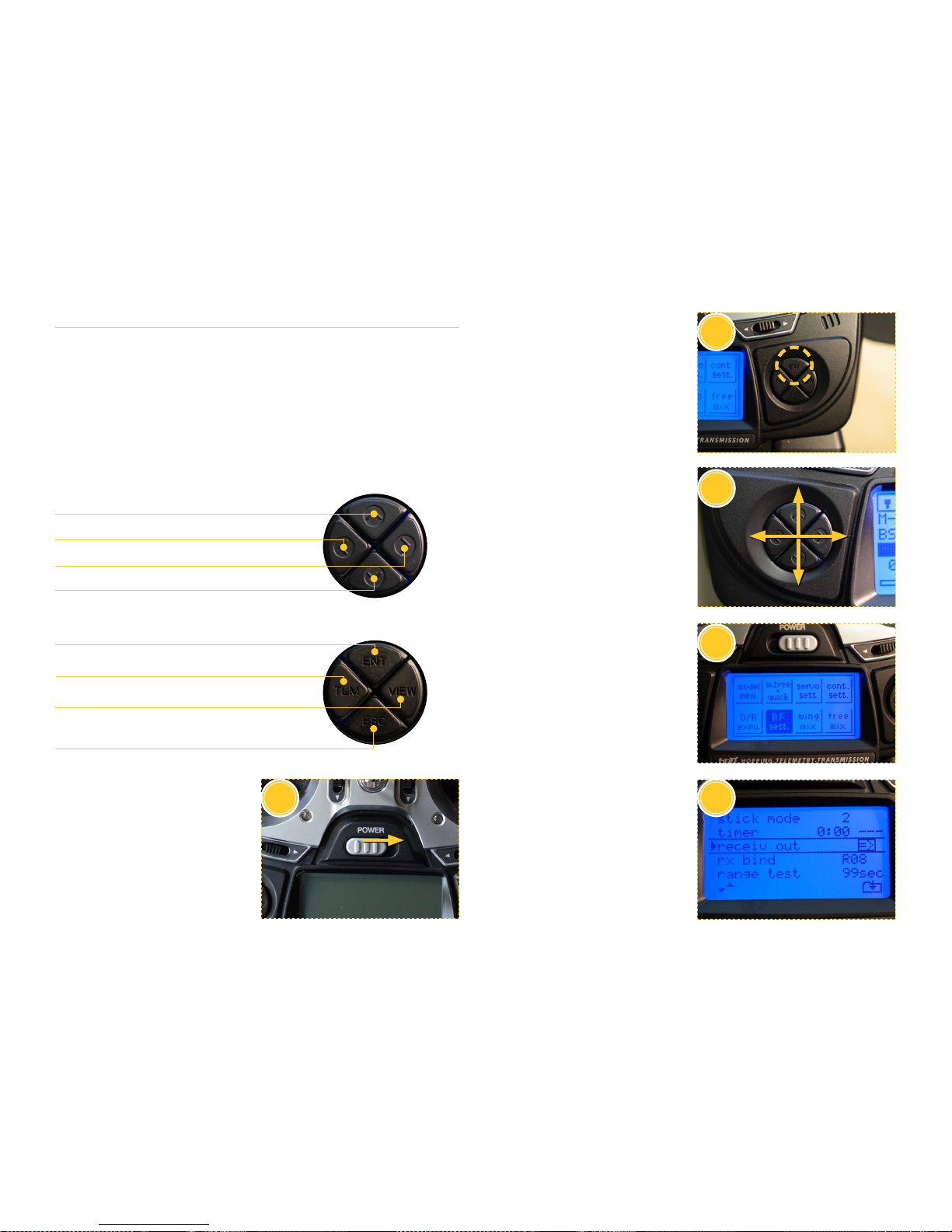
OPERATING MODES
Correct MZ-12 prole for default operation
Below are the steps to properly congure your MZ-12 prole to operate with your
BeSteady FOUR as pictured on the previous page. The MZ-12 should arrive with this
prole precongured. Follow the steps to restore the prole should anything happen to it.
The Graupner MZ-12 radio is a semi-professional remote control system and features
many advanced functions. A separate manual for advanced RC users is included with the
system. This manual describes the operation necessary to work with BeSteady FOUR only.
IMPORTANT: for safety, battery, maintenance and troubleshooting instructions of the
MZ-12 radio system please refer to the separate Graupner MZ-12 Manual. BeSteady LTD
shall not be held responsible for any malfunctions or damage caused by inappropriate
handling or failure to follow the manufacturers instructions.
1. Insert the 4 AA batteries into your
MZ-12 and use the power switch
to turn it on.
5
1
3
4
2
Navigate / choose UP
Navigate / choose LEFT
Navigate / choose RIGHT
Navigate / choose DOWN
ENT
Enter menu or submenu / proceed or conrm action / input data.
TLM
View telemetry data screen (non-functional with BeSteady FOUR).
VIEW
View currently mapped channels position bars.
Move the controls that are on active channels to see live signal input.
ESC
Enter previous menu or submenu / go back / cancel input.
x2
MZ-12 Navigation Panel
MZ-12 Action Panel
2. Press the ENT on the Action Panel
button twice to enter the main
menu
3. Use the Navigation Panel to move
arround the main menu. These
button are also used to choose,
toggle and switch particular options.
4. Choose the RF sett. and press ENT.
5. Chose the receiv out option and
press ENT.
30
Page 31
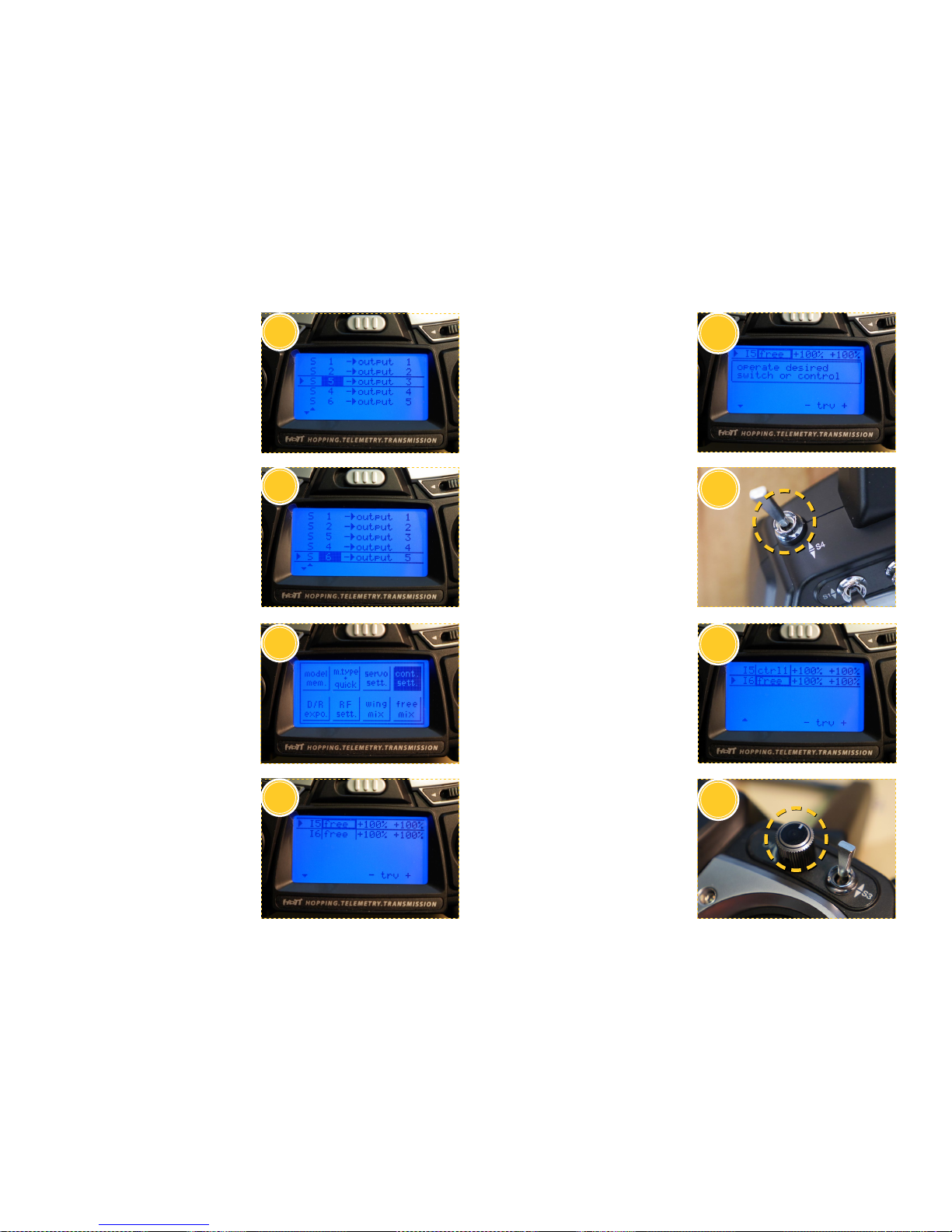
7
8
6
6. Set the control S 5 to work on
output channel 3 as pictured.
10. Press ENT button on channel 5 (I5)
to enable the mapping mode for this
channel. An information window will
appear as pictured.
11. Switch the S4 three-way toggle
switch to map it to channel 5. The
switch is located on the back of the
left side of the RCU.
12. Notice that the channel 5 status
changed to ctrl1 meaning that a
control has been mapped to this
channel, in this case - the S4 switch.
Choose the channel 6 (I6) status
and press ENT to enter the mapping
mode for channel 6.
13. Operate the DV potentiometer in
any direction to map it to channel 6.
The DV control is located on the
right side of the RCU, next to the S3
toggle switch.
7. Set the control S 6 to work on
output channel 5 as pictured.
8. Use the ESC button to go back to the
main menu and choose cont. sett.
9. A menu showing the mapping of
channels 5 and 6 will show up.
Notice that these channels are
marked free - that means that there
is no control operating on these
channels.
9
10
11
12
13
31
Page 32
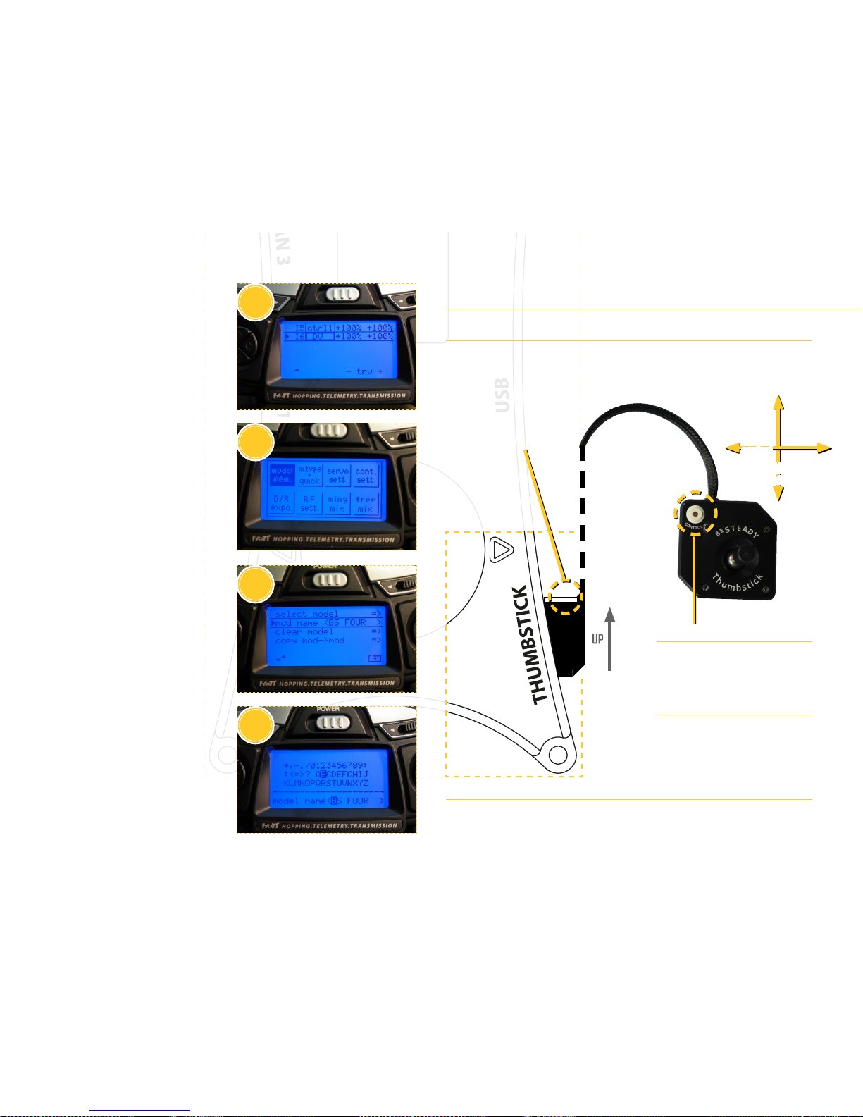
OPERATING MODES
14
15
16
17
14. The channel 6 status should change
to DV.
15. Use the ESC button to go back to
the main menu and choose model
mem., press ENT.
16. Choose the mod name option and
press ENT.
17. Use the Navigation Panel and ENT
button to enter your prole name
that you have just congured.
This will save all the channel and
control settings that were input into
the prole and you will be able to
restore it with the select model
option from the model mem. menu.
The recommended model name is
BS FOUR.
BeSteady Thumbstick setup
Connecting the BeSteady Thumbstick
The BeSteady Thumbstick was designed to be a plug-n-play device for your BeSteady
FOUR. Just connect your BeSteady Thumbstick as pictured below. The Thumbstick can
operate along with a connected RCU device (such as the Graupner MZ-12) which means
that you can have two seperate remote control sources at once - the Thumbstick for the
gimbal holder and an external radio for the second operator.
WARNING
Always connect the Thumbstick while the BeSteady is NOT powered up from the battery
or from USB port! Do NOT connect the Thumbstick to the Remote port! Make sure that
the Thumbstick plug is connected the right way before powering up your gimbal!
Painted / marked side
to the top
Tilt
control
Pan
control
Thumbstick Control Button
The Control Button on the Thumbstick works
the same way as the central Control Button on
the BeSteady FOUR. It is congurable and can
perform the same actions as the main Control
Button.
Adjusting Thumbstick control
All the settings that are available in the Control
menu of the OnBoard Manager are also
affecting the Thumbstick signal input. Feel free
to adjust the expo rate, deadband and speed to
your preference.
32
Page 33
33
Page 34
www.besteady.eu
 Loading...