

Page 1

Best Data Products Inc.
DSL502E_EU
User’s Manual
Revision 1.0
Page 2

Page 3

Best Data DSL542 User’s Guide
Copyright
This manual m a y not be c opie d, p hotoc op ie d, tra nsm i tte d, or tr a ns late d i n to l an gua ge or com put er
language, in any form, or by any means, in whole or in part, without the prior written consent by the
manufacturer.
© Copyright 2002 All rights reserved.
Disclaimer
The manufacturer makes no representations or warranties, express ed , s tat utor y or im plie d, r eg ard in g
the fitness or merchantability of this product for any particular purpose. Further, the manufacturer is
no liable for any dam a ges, inc l udin g b ut n ot lim ite d t o, l ost pr ofits , los t sa vin g, o r othe r i nc ide nta l or
consequentia l d ama ge s ar is ing ou t of t he u se of thi s product. The manufacturer also reserves the right
to make any improvements or modifications to the product described in this manual at any time,
without notice of these changes.
i
Page 4

Best Data DSL542 ADSL Ethernet Router User’s Guide
Federal Communications Commission (FCC) NOTICE
This equipment has been tested and found to comply with the limits for a Class B digital device,
pursuant to Part 15 of FCC Rules. These limits are designed to provide reasonable protection against
harmful interference in a residential installation. This equipment generates, uses and can radiate radio
frequency energy and, if not installed and used in accordance with the instructions, may cause harmful
interference to radio communications. However, there is no guarantee that interference will not occur
in a particular installation. If this equipment does cause harmful interference to radio or television
reception, which can be determined by turning the equipment off and on, the user is encouraged to try
to correct the interference by one or more of the following measures:
z Reorient of relocate the receiving antenna.
z Increase the separation between the equipment and receiver.
z Connect the equipment into an outlet on a circuit different from that to which the receiver is
connected.
z Consult the dealer or an experienced radio / TV technician for help.
This unit was tested with shielded cables on the peripheral devices. Shielded cables must be used
with the unit to insure compliance. This statement can be deleted if unit was not tested with
shielded cables.
The manufacture is not responsible for any radio or TV interference caused by unauthorized
modifications to this equipment. Such modifications could void the user's authority to operate the
equipment.
This device complies with Part 15 of the FCC rules. Operation is subject to the following two
conditions:
1. This device may not cause harmful interference.
2. This device must accept any interference that may cause undesired operation.
CAUTION
Always disconnect all telephone lines from the wall outlet before servicing or disassembling this
equipment.
ii
Page 5

Best Data DSL542 User’s Guide
IMPORTANT SAFETY INSTRUCTIONS
When using your telephone equipment, basic safety precautions should always be followed to reduce
the risk of fire, electric shock and injury to persons, including the following;
1. Do not use this product near water, for example near a bath tub, wash bowl, kitchen sink or
laundry tub, in a wet basement or near a swimming pool.
2. Avoid using a telephone (other then a cordless type) during an electrical storm. There may be a
remote risk of electr ic shoc k from ligh ting.
3. Do not use the telephone to report a gas leak in the vicinity of the Leak.
4. Use only the power cord and batteries indicated in this manual. Do not dispose of batteries in a
fire. They may explode. Check with local codes for possible special disposal Instructions.
SAVE THESE INSTRUCTIONS
Comment [CT1]: Add FCC
statements, legal, copyright info, etc.
Your equipment must be designed to
meet all appropriate UL, IEC, FCC,
and other requirements which apply
to the jurisdiction where it will be
used. For example, “This equipment
has been tested and found to comply
with the limits for a Class B digital
device, pursuant to part 15 of the
FCC Rules . ”
iii
Page 6

Best Data DSL542 ADSL Ethernet Router User’s Guide
Table of Contents
1 INTRODUCT ION.............................................. ....... ....... ....... ....... .... ....... ....... ....... ....... .....1
Features............................................................................................................................................................... 1
System Requirements........................................................................................................................................ 1
2 GETTING TO K N O W TH E B ES T D A TA DSL542.................... ... ........ ....... ....... ....... ....... .2
Parts Check......................................................................................................................................................... 2
Front Panel......................................................................................................................................................... 3
Rear Panel........................................................................................................................................................... 4
3 HARDWARE C ONN EC TI ON AN D PC CO NF IGU RA T ION.......................... ........... ........5
Connecting Your Best Data DSL 542...............................................................................................................5
Configuring Your Computers..........................................................................................................................6
4 GETTING STA RT ED W ITH TH E C ON FI GUR A TION MA NA GE R................................15
Accessing the Configuration Manager..........................................................................................................15
Functional Layout............................................................................................................................................16
Changing Your Login Password.................................................................................................................... 17
Committing Your Changes and Rebooting the Device...............................................................................17
5 SETTING TH E L AN IP A DDR ESS.................................................. ........... ....... .......... ...19
Ethernet, USB, or Both?................................................................................................................................. 19
Configuring the LAN IP Address..................................................................................................................19
Configuring the USB Port IP Address..........................................................................................................21
iv
Page 7

Best Data DSL542 ADSL Ethernet Router User’s Guide
6 CONFIGURIN G DYN A MIC H OST C ON FI GUR A TION PR OTO CO L............................23
Configuring DHCP Server............................................................................................................................. 23
Configuring DHCP Relay...............................................................................................................................27
Setting the DHCP Mode.................................................................................................................................. 28
7 CONFIGURING NETWORK ADDRESS TRANSLATION.............................................29
Your Default NAT Setup................................................................................................................................29
Viewing NAT Global Settings and Statistics............................................................................................... 29
Viewing NAT Rules and Rule Statistics........................................................................................................31
Viewing Current NAT Translations..............................................................................................................32
Adding NAT Rules........................................................................................................................................... 33
8 CONFIGURI NG IP ROU TE S...................................... ....... .......... ........... ........... ........... ..41
Viewing the IP Routing Table........................................................................................................................ 41
Adding IP Routes............................................................................................................................................. 42
9 CONFIGURIN G THE ATM VCC............................................... ....... ....... .... ....... ....... ......44
Viewing Your ATM VC Setup....................................................................................................................... 44
Adding ATM VCCs.........................................................................................................................................45
Modifying ATM VCCs.................................................................................................................................... 46
10 CONFIGURING PPP IN TE R FAC ES................................................... .......... ..........47
Viewing Your Current PPP Configuration..................................................................................................47
Viewing PPP Interface Details.......................................................................................................................49
Adding a PPP Interface Definition................................................................................................................ 51
Modifying and Deleting PPP Interfaces........................................................................................................ 52
v
Page 8

Best Data DSL542 ADSL Ethernet Router User’s Guide
11 CONFIGURING EOA INTERFACES............................................................ ..........53
Viewing Your EOA Setup............................................................................................................................... 53
Adding EOA Interfaces................................................................................................................................... 54
12 CONFIGURING IP OA INTE RFA CES............................................................... ......56
Viewing Your IPoA Interface Setup.............................................................................................................. 56
Adding IPoA Interfaces................................................................................................................................... 57
13 CONFIGURING BR IDG IN G.......................................................................... ........ ..59
Using the Bridging Feature.............................................................................................................................59
Defining Bridge Interfaces..............................................................................................................................59
Deleting a Bridge Interface............................................................................................................................. 60
A TROUBLESHOOTING.............................................................. ....... ....... ....... ........ ....... ..61
Diagnosing Problem using IP Utilities........................................................................................................... 63
vi
Page 9

Best Data DSL542 ADSL Ethernet Router User’s Guide
1 Introduction
Congratulations on becoming the own er of the B est D ata DSL542 A DSL Ether net bridge /rout er.
Your LAN (local area network) will now be able to access the Internet using your high-speed
ADSL connection.
This User Guide will show you h ow to inst all and set up the Best Data DSL542 ADSL
Bridge/Router, and how to customize its configurat ion to get the most out of your ne w product.
Features
f Internal ADSL modem for high-speed Internet access
f 10/100Base-T Ethernet router to provide I nternet co nnectivity to all compu ters on y our
LAN
f USB port for connecting a USB-enabled PC (Option)
f Network address translation (NAT), Firewall, and IP filtering functions to provide security
for your LAN
f Network configuration through DHCP Server and DHC P Relay
f Services including IP route and DNS con figuration , RIP, and IP and DSL pe rformanc e
monitoring
f Configuration program you access via an HTML browser
System Requirements
In order to use the Best Data DSL542 ADSL /Ethernet router, y ou must have the foll owing :
f ADSL service up and running on your teleph one line , with at least on e public Internet
address for your LAN
f One or more computers each containing an Ethernet 10Base-T/100Base-T network
interface card (NIC) and/or a single computer with a USB port
f An Ethernet hub/switch, if you are connecting the device to more than one computer on
an Ethernet network.
For system configuration using the sup plie d web-based program : a web brow ser suc h as
Internet Explorer v5.0 or later, or Netscape v4.7 or later
1
Page 10

Best Data DSL542 ADSL Ethernet Router User’s Guide
2 Getting to Know the Best Data DSL542
Parts Check
In addition to this document, your Best Data DSL5 42 should arrive with the follow ing:
f One Best Data DSL542 ADSL E thernet Bri dge/Rout er
f One Power adapter and power cord
f One USB cable (Option)
f One Ethernet cable (“straight-through” type)
f One RJ-11 telephone cord
f One CD-ROM (This manual and/or USB Driver)
2
Page 11
Best Data DSL542 ADSL Ethernet Router User’s Guide
Front Panel
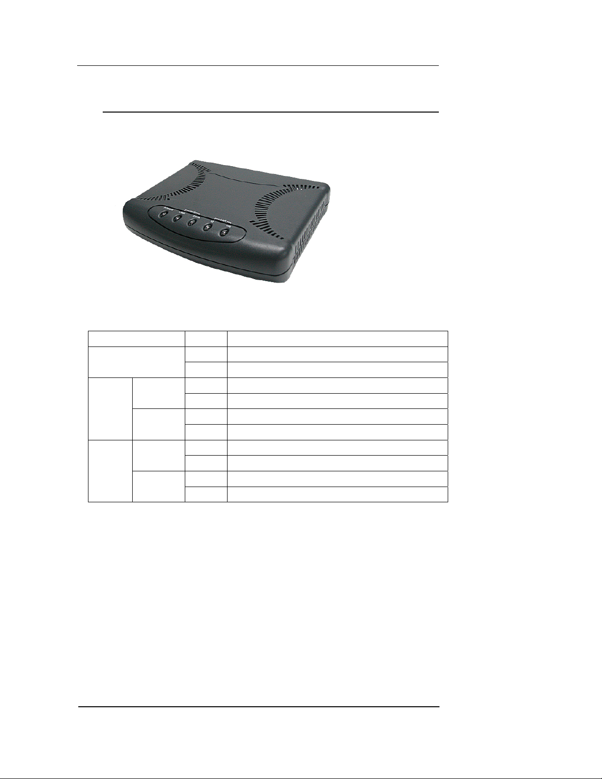
The front panel contains lights calle d LEDs tha t indica te the sta tus of the u nit.
LED Status Description
POWER
LINK
WAN
DATA
10
LAN
100
Figure 1. Front Panel and LEDs
Glowing
Power on
Dim Power off
Glowing
The WAN port is successfully linked with ADSL line
Dim The WAN port is not linked with any ADS L line
Glowing The WAN port is receiving/transmitting da ta
Dim The WAN port is not receiving/transmitting data
Glowing The LAN port is connected to a 100M Etherne t device
Flashing The LAN port is receiving/transmitting data
Glowing The LAN port is connected to a 10M Ethernet de vice
Dim The LAN port is receiving/transmitting data
3
Page 12
Best Data DSL542 ADSL Ethernet Router User’s Guide
A
Rear Panel
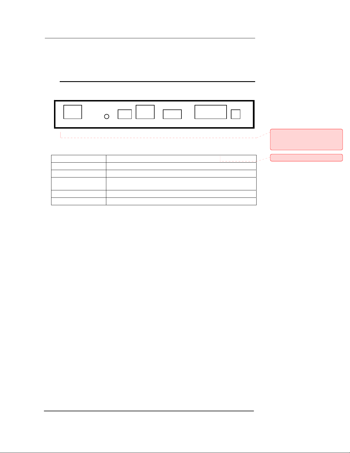
The rear panel contains the ports for the unit's data and power connections.
DSL Reset USB LAN CD-INPOWER Switc hCONSOLE
Figure 2. Rear Panel Connectio ns
ADSL Connects the device to the wall jack for Internet connection
RESET Resets the device to default configuration values.
USB (Option) Connects to the USB port on your PC.
LAN
CONSOLE (Option) Using a special cable to connect to your computer for configuration
DC IN Connects to the supplied power converter cable.
Connects the device to your PC's Ethernet port, or to the uplink port on your
LAN's hub, using the cable provided.
Comment [CT2]: Insert photo of
front-panel LED. Also, change table
to reflect the LEDs you implemented
and their labels.
Comment [CT3]: True?
4
Page 13
Best Data DSL542 ADSL Ethernet Router User’s Guide
A
3 Hardware Connection and PC
configuration
Connecting Your Best Data DSL542
In this part, you connect the device to the phone jack, the power outlet, and your computer
or network.
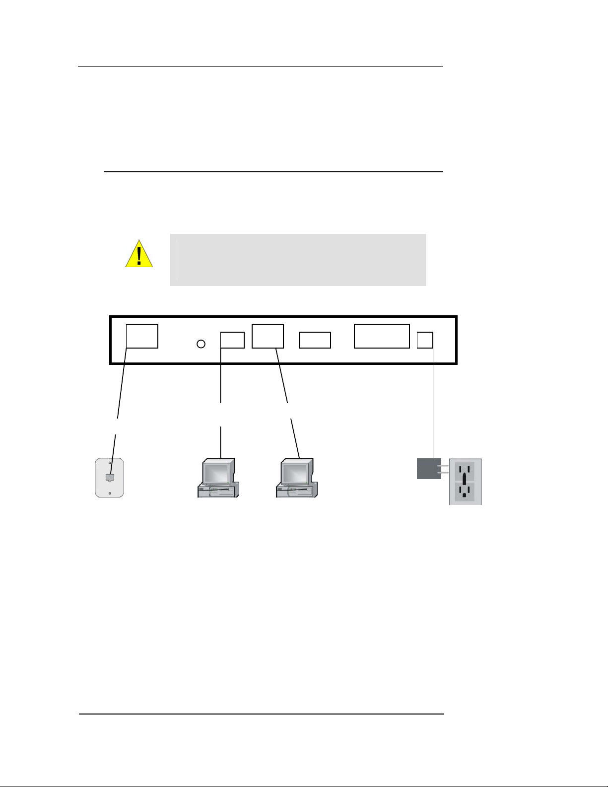
Figure 4 illustrates the hardware conne ctions. Re fer to the s teps tha t follow for specific
instructions.
Before you begin, turn the power off for all devices. Th ese
include your computer(s), your LAN hu b/switch (if applic able),
WARNING
DSL Reset USB LAN CD-IN POWER Switc hCONSOLE
RJ-11 cord
and the Best Data DSL542.
USB Cable
(Option)
Computer
Figure 3. Overview of Hardware Connections
Ethernet Cable
Computer
Adaptor
Wall Outlet
5
Page 14

Best Data DSL542 ADSL Ethernet Router User’s Guide
Step 1. Connect the ADSL cable
Connect one end of the provided phone cable to the port labeled ADSL on the rear panel of
the device. Connect the other end to y our wall phone jac k.
Step 2. Connect the Ethernet cable.
If you are connecting a LAN to the Bes t Da ta DS L542 AD SL/Ethe rnet route r, a ttach one
end of a provided Ethernet cable to a regular hub port and the other to the Ethernet port on
the Best Data DSL542.
If you are using the Best Data DSL542 with a single computer and no hub, you must use a
“crossover” Ethernet cable (not provided) to attach the PC directly to the device. The
crossover cable is wired differently than the cable you would use to connect to a hub.
When you compare the colored wire s on each end of a s traight-thro ugh cab le, they w ill be
in the same sequence; on crossover cables, they w ill not. Cont act y our ISP for assis tance.
Step 3. Attach the power connector.
Connect the AC power adapter to the PWR connector labeled DC IN on the back of the
device and plug in the adapter to a wa ll outlet or power strip .
Step 4. Power up your systems.
Turn on and boot up your computer(s) and any LAN devi ces suc h as hubs o r switches .
Step 5: Install USB software and connect the USB cable. (USB port is ontiona l)
You can attach a single computer to the device using a USB cable. The USB port is useful
if you have an USB-enabled PC that does not have a network interface card for attaching
to your Ethernet network.
Before attaching the USB cable, you must in stall a USB driver and con figure the c omputer .
For complete instructions, see page 10.
Configuring Your Computers
This part provides instructions for configuring the Internet settings on your computers to
work with the Best Data DSL542.
Before you begin
By default, the Best Data DSL542 automatically assigns all required Internet settings to
your PCs. You need only to configure the PCs to accept the information when it is
assigned.
In some cases, you may want to assign Internet information
manually to some or all of your computers rather than allow the Best
Note
f If you have connected your PC via the USB port, see the USB configuration
instructions on page 10.
f If you ha ve connect ed your PC of LAN via Ethernet to the Best Data DSL542,
follow the instructions that correspond to the operating system installed on your
PC.
6
Data DSL542 to do so. See “Assigning static In terne t
information to your PCs” on page 9 for instructio ns.
Page 15

Best Data DSL542 ADSL Ethernet Router User’s Guide
Windows® 95, 98 PCs:
First, check for the IP protocol and, if necess ary, insta ll it:
1. In the Windows task bar, click the Start button, point to Settings, and then click
Control Panel.
2. Double-click the Network icon.
The Network dialog box displays with a list of currently installed network components.
If the list includes TCP/IP, and then the pr otocol ha s already been enab led. Skip to
step 9.
3. If TCP/IP does not display as an installed component, click
.
The Select Network Component Type dial og box displays.
4. Select Protocol, and then click
.
The Select Network Protocol dialog box display s.
5. Click on Microsoft in the Manufacturers list box, and then click TCP/IP in the
Network Protocols list box.
6. Click
to return to the Network dial og box, and then click
again.
You may be prompted to install files from your W indows 95/ 98 ins tallation CD. Fo llow
the instructions to install the file s.
7. Click
to restart the PC and complete the TCP/IP installation.
Next, configure the PCs to accept IP information assigned by the Best Data DSL542:
8. Open the Control Pan el window, and then click the Network icon.
9. Select the network component labeled TCP/IP, and then click
If you have multiple TCP/IP listings, select the listing associated with your network
card or adapter.
10. In the TCP/IP Properties dialog box, click the IP Address tab.
11. Click the radio button labeled Obtain an IP address automatically.
12. Click the DNS Configuration tab, and then click the radio button labeled Obtain
an IP address automatically.
.
13. Click
twice to confirm and save your changes.
You will be prompted to restart Windows.
14. Click
.
Windows NT 4.0 workstations:
First, check for the IP protocol and , if neces sary, insta ll it:
1. In the Windows NT task bar, click the Start but ton, point to Settings, and then
click Control Panel.
2. In the Control Panel window, double click the Network icon.
3. In the Network dialog box, click the Protocols tab.
7
Page 16

Best Data DSL542 ADSL Ethernet Router User’s Guide
The Protocols tab displays a list of currently installed network protocols. If the list
includes TCP/IP, then the protocol has already been enabled. Skip to step 9.
4. If TCP/IP does not display as an installed component, click
.
5. In the Select Network Protocol dialog box, select TCP/IP, and then click
.
You may be prompted to install files fr om your W indows NT installatio n CD or othe r
media. Follow the instructions to install th e file s.
After all files are installed, a window displays to inform you that a TCP/IP service
called DHCP can be set up to dynamically assign IP information.
6. Click
to continue, and then clic k if prompted to restart
your computer.
Next, configure the PCs to accept IP information assigned by the Best Data DSL542:
7. Open the Control Pan el window, and then double-click the Network icon.
8. In the Network dialog box, click the Protocols tab.
9. In the Protocols tab, select TCP/IP, and then click
.
10. In the Microsoft TCP/IP Pro perties dialog box, click the radio button labeled
Obtain an IP address from a DHCP server.
11. Click
twice to confirm and save your changes, and then close the
Control Panel.
Windows 2000 PCs:
First, check for the IP protocol and , if neces sary, insta ll it:
1. In the Windows task bar, click the Start button, point to Settings, and then click
Control Panel.
2. Double-click the Network and Dial-up Connections icon.
3. In the Network and Dial-up Connections window, right-click the Local Area
Connection icon, and then select Properties.
The Local Area Connection Properties dialog box displays with a list of currently
installed network components. If the list in cludes Intern et Protoco l (TCP/IP), th en the
protocol has already been enabled. Skip to step 10.
4. If Internet Protocol (TCP/IP) does not display as an installed component, click
.
5. In the Select Network Component Type dialog box, select Protocol, and then
click
.
6. Select Internet Protocol (TCP/IP) in the Network Protocols list, and then click
.
You may be prompted to install files f rom your W indows 200 0 installa tion CD or other
media. Follow the instructions to install th e file s.
7. If prompted, click
to restart your computer with the new settings.
Next, configure the PCs to accept IP information assigned by the Best Data DSL542:
8. In the Control Panel, double-click the Network and Dial-up Connections icon.
8
Page 17

Best Data DSL542 ADSL Ethernet Router User’s Guide
9. In Network and Dial-up Connec t io ns wind o w, righ t -cl i ck the Loc al Are a
Connection icon, and then select Properties.
10. In the Local Area Connection Properties dialog box, select Internet Protocol
(TCP/IP), and then click
.
11. In the Internet Protocol (TCP/IP) Properties dialog box, click the radio b utton
labeled Obtain an IP address automatically. Also click the radio button labeled
Obtain DNS server address automatically.
12. Click
twice to confirm and save your changes, and then close the
Control Panel.
Windows Me PCs
1. In the Windows task bar, click the Start button, point to Settings, and then click
Control Panel.
2. Double-click the Network and Dial-up Connections icon.
3. In the Network and Dial-up Connections window, right-click the Network icon,
and then select Properties.
The Network Properties dialog box displays with a list of currently installed network
components. If the list includes Internet Protocol (TCP/IP), then the protocol has
already been enabled. Skip to step 11.
4. If Internet Protocol (TCP/IP) does not display as an installed component, click
.
5. In the Select Network Component Type dialog box, select Protocol, and then
click
.
6. Select Microsoft in the Manufacturers box.
7. Select Internet Protocol (TCP/IP) in the Network Protocols list, and then click
.
You may be prompted to install files from your Windows Me installation CD or other
media. Follow the instructions to install th e files.
8. If prompted, click
to restart your computer with the new settings.
Next, configure the PCs to accept IP information assigned by the Best Data DSL542:
9. In the Control Panel, double-click the Network and Dial-up Connections icon.
10. In Network and Dial-up Connections window, right-click the Network ico n, and
then select Properties.
11. In the Network Properties dialog box, select TCP/IP, and then click
.
12. In the TCP/IP Settings dialog box, click the radio button labeled Server
assigned IP address. Also click the radio button labeled Server assigned
name server address.
13. Click
twice to confirm and save your changes, and then close the
Control Panel.
Assigning static Internet information to your PCs
9
Page 18

Best Data DSL542 ADSL Ethernet Router User’s Guide
f In some cases, you may want to assign Internet information to some or all of your
PCs directly (often called “statically”), rather than allow ing the Best Data DSL 542
to assign it.
Before you begin, contact your ISP if you do no t already have th e follo wing informati on:
f The IP address an d subne t mask t o be ass igned to each PC to which y ou will be
assigning static IP information.
f The IP address of the default gatew ay for your LAN. In mo st cases, t his is the
address assigned to the LAN port on the Bes t Data DSL542 . By default, the LAN
port is assigned this IP address: 192.168.1.1. (You can change this number, or
another number can be assigned by your ISP. See Chapter 5 for more
information.)
f The IP address of your ISP’s Domain Name System (DNS) server.
On each PC to which you want to assign static information, follow the instructions on pages
7 through 9 relating only to checking for and/or installing the IP protocol. Once it is installed,
continue to follow the instructions for displaying each of the Internet Protocol (TCP/IP)
properties. Instead of enabling dynamic assignment of the IP addresses for the computer,
DNS server, and default gateway; click the radio buttons that enable you to enter the
information manually.
Your PCs must have IP addresses that place them in the same
subnet as the Best Data DSL542’s LAN port. If you ma nually as sign
Note
IP information to all your LAN PCs, you can follow the instructions in
Chapter 5 to change the LAN port IP address accordingly.
Configuring a computer connected to the USB port
If the Best Data DSL542 includes a USB port for connec ting to a PC, you must ins tall the
provided USB driver software on the PC. The driver enables Ethernet-over-USB
communication with the Best Data D SL542.
Configuring the USB computer is a two-part process:
f In Part 1, you install the USB driver on the PC.
f In Part 2, you configure the IP properties on the USB PC .
Before you start to install USB driver, you shall cr eate an en try for US B port via RS -232
serial cable.
1. Connect an RS-232 cable from one serial COM port on your PC to the Best Data
DSL542
2. In Windows, go to Start → Programs →Accessori es → Communications →
HyperTerminal
3. When the HyperTerminal window appears, double-click Hypertrm to start a new
session.
4. Name the new connection and select an icon for this session
5. In the Conne ct To dialog box, select the COM port that you used to connect to
this product.
6. In the COM port Properties dialog box, set the serial port setting at 38400 ba ud
rate, 8 bit, none parity, none flow contr ol.
7. Type “create usb intf ifname usb-0 ip 198.168.1.2 mask 255.255.255.0 inside”
then Enter
8. You will see “Entry created” then you have to type “commit” to save this entry.
10
Page 19
Best Data DSL542 ADSL Ethernet Router User’s Guide
Part 1. Installing the USB Driver:
1. Ensure that the USB cable is not connected to the USB port on the PC or to the
USB port on the Best Data DSL542. The installation program will prompt you
when to connect the cable.
2. Copy the USB installation file to a temporary directory on the USB computer.
3. In the folder where you copied the files, double-click on setup.exe to start the
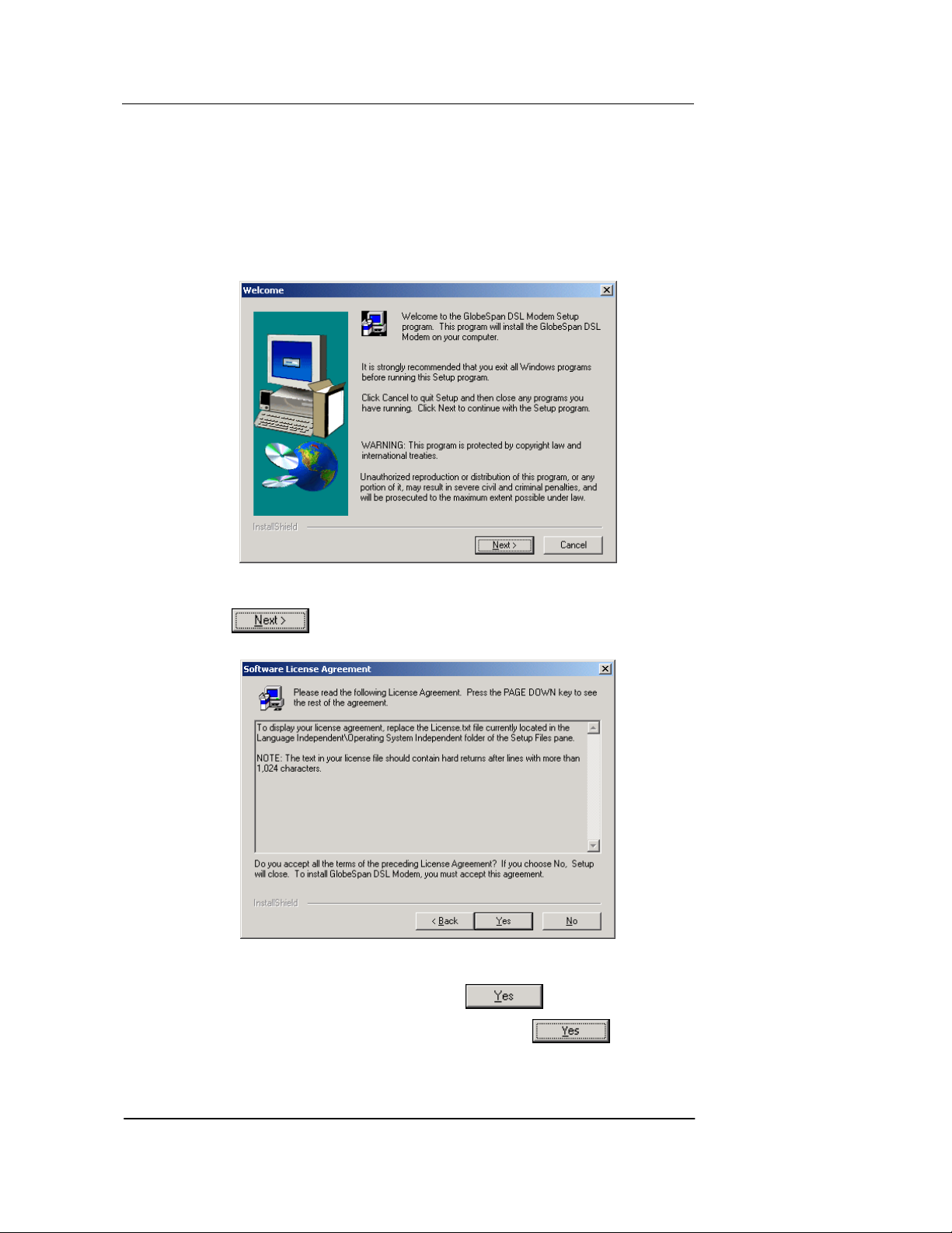
installation program. The Welc o m e dialo g box displ ays, as shown i n Fi gu re :
Figure 4. USB Driver Installat ion: Welc ome Sc reen
4. Click
to display the Software License Agreement dialog box, as
shown in Figure .
Figure 5. USB Driver Installation: Software License Agreement
5. After reviewing the license agreement, click
to continue.
6. If a Microsoft digital signature dialog box displays, click
11
to continue.
Page 20
Best Data DSL542 ADSL Ethernet Router User’s Guide
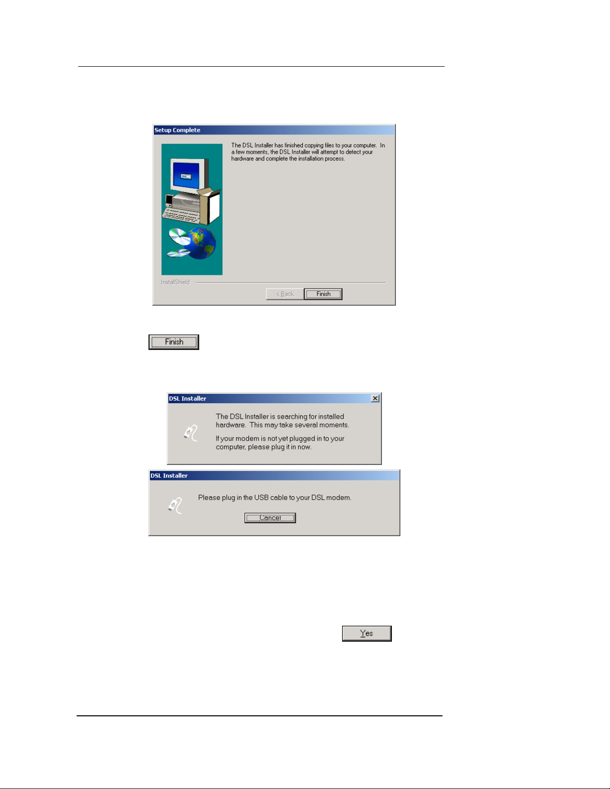
The installation program will begin copying the neces sary installation files to the
required locations. When finishe d, the Setup Comp lete dia log box will display , as
shown in Figure .
Figure 6. USB Driver Installation: Setup Complete
7. Click
.
A DSL Installer dialog box displays while the program s earches for your US B
hardware. After a few seconds, a second dialog box displays to prompt you to attach
the USB cable, as shown in Figure .
Figure 7. USB Driver Installation: DSL Installer
8. Attach the USB cable to the Best Data DSL542 and to your PC.
The USB cable provided has a flat connector on one end (called Type A) and a square
connector on the other (Type B). Connect the fla t conne ctor to your P C and the square
connector to the Best Data DSL542.
A window displays briefly, indicating that the system has found new hardware.
9. If a Microsoft di gital signature dialog box displays, click
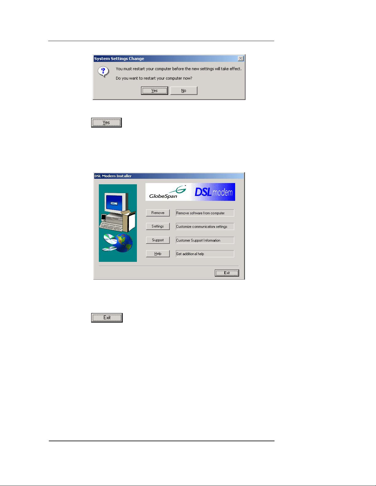
The System Settings Change dialog box dis play s to prompt you to restart your
computer, as shown in Figure :
12
to continue.
Page 21
Best Data DSL542 ADSL Ethernet Router User’s Guide
Figure 8. USB Driver Installation: System S ettings Change
9. Click
to restart your computer.
When your computer finishes rebooting, make sure that the GlobeSpan installer program
displays as an item on y our W indows Sta rt menu:
10. Click the Start button, point to Programs » GlobeSpan DSL Modem, and click
on Configure.
The DSL Modem Installer dialog box should display , as shown in Figure .
Figure 9. DSL Modem Installer Dialog Box
This step is only verification. You do not need to access the configuration program at this
time.
11. Click
.
Part 2. Configuring IP properties on the USB PC.
Now that the USB driver installation is c omplete, y ou must co nfigure the USB PC s o that its
IP properties place it on the same subnet as the Best Data DSL542’s USB port. There are
two ways to do this:
f Th e Best Data DSL542 is con figured to a ssign an ap propriate IP address to the
USB PC. If you want to use this automatic assignment feature, called “DHCP
server,” you must configure the USB PC to accept dynamically assigned IP
information. Follow the instruction on pages 7 through 9 that correspond to the
operating system installed on the PC.
f If y ou want to assign a stat ic IP add ress to the PC , follow the instr uctions on page 9
and use the following information.
• In the Network and Dial-up Connections window, be sure to select the icon th at
corresponds to your new USB connection (not the one that corresponds to your
13
Page 22

Best Data DSL542 ADSL Ethernet Router User’s Guide
Ethernet NIC). When you display the pro perties for t he icon, the follow ing text
should display in the Connect Using text box:
GlobeSpan USB IAD LAN Modem #n
• The USB port on the Best Data DSL542 is preconfigured with these properties
(you cannot change these values):
USB port IP address: 198.168.1.2
USB port subnet mask: 255.255.255.0
Therefore, your PC must be configured as follows:
IP address: 192.168.2.n where n is a
number from 2 to 254.
Subnet mask: 255.255.255.0
Default gateway: 198 .168.1.2
Default Router Settings
In addition to handling the DSL connection to y our ISP, t he Best Da ta DSL542
ADSL/Ethernet router can provide a variety of services to your network. The device
is preconfigured with default settings fo r use wi th a typical home or sma ll office
network.
Table 1 lists some of the most important default settings; these and other features
are described fully in the subs equent ch apters. If you are fam iliar w ith network
configuration, review the settings in Table 1 to verify that they meet the needs of your
network. Follow the instructions to change the m if ne cessary. If you are un familiar
with these settings, try using the device without modification, or contact your ISP for
assistance.
Before you modifying any settings, review C hapter 4 for gen eral info rmation abo ut
accessing and using the Configuration Manager program. We strongly recommend
that you contact your ISP prior to changing the default configuration.
Table 1. Default Settings Summary
Option Default Setting Explanation/Instructions
DHCP (Dynamic
Host Configuration
Protocol)
NAT (Network
Address Translation)
LAN Port
IP Address
USB Port
IP Address
DHCP server enabled with two pools
of addresses:
For LAN computers:
192.168.1.3 through 192.168.1.34
For USB computer:
192.168.1.2 (for both, subnet mask
= 255.255.255.0)
napt rule enabled Your computers’ private IP addresses
Static IP address: 192.168.1.1
subnet mask: 255.255.255.0
Assigned static IP address:
198.168.1.2
subnet mask: 255.255.255.0
The Best Data DSL542 maintains a pool
of 32 private IP addresses for dynamic
assignment to your LAN computers and a
pool containing 1 IP address for
assignment to your USB computer. To
use this service, you must have set up
your computers to accept IP information
dynamically. See Chapter 6 for an
explanation of the DHCP service.
(see DHCP above) will be translated to
your public IP address whenever they
access the Internet. See Chapter 7 for a
description of the NAT service.
This is the IP address of the LAN port on
the device. The LAN port connects the
device to your Ethernet network.
Typically, you will not need to cha nge this
address. See Chapter 5 for instructions.
This is the IP address assigned to the
USB port on the device (if used).
Typically, you will not need to cha nge this
address. See Chapter 5 for instructions.
14
Page 23
Best Data DSL542 ADSL Ethernet Router User’s Guide
4 Getting S tarted with the Configuration
Manager
The Best Data DSL542 includes preinstalled program called the Configuration Manager,
which provides an interface to the software installed on the device. It enables you to
configure the device settings to meet the nee ds of your network. Y ou access it th roug h
your web browser from any PC connected to the Best Data DSL542 via
The Best Data DSL542 may already be configured to provide
Internet connectivity for your net work. If it works pr operly wit h the
preconfigured settings, then you may not need t o use the
Note
Configuration Manager. Contact your ISP to determine which
settings you may need to change, if any.
Accessing the Configuration Manager
The Configuration Manager program is preinstalled into memory on the Best Data DSL542.
To access the program, you need the following:
f A PC or laptop connected to the LAN port on the Best Data DSL542.
f A web browser installed on the PC. The program is designed to work best with
Microsoft Internet Explorer® version 5.0, Netscape Navigator® version 4.7, or later
versions .
You can access the program from any computer connected to the Best Data DSL542 via
the LAN or USB ports.
1. From a LAN computer, open your web browser, type the following URL in the web
address (or location) box, and press <Enter>:
http://192.168.1.1
Or, from the USB computer, type:
http://198.168.1.2
These are the predefined IP addresses for the LAN and USB ports on the Be st Data
DSL542.
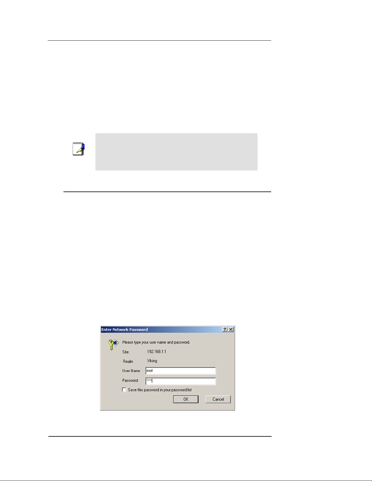
A login screen displays, as shown in Figure .
the LAN port.
Figure 10. Login Screen
15
Page 24
Best Data DSL542 ADSL Ethernet Router User’s Guide
2. Enter your user name and passwo rd, and then click .
3. The first time you log into the program, use t hese defaults:
Default User Name: root
Default Password:
root
You can change the password at any time (see Changing Your
Note
Login Password on page 17). The user name can not be c hanged.
Functional Layout
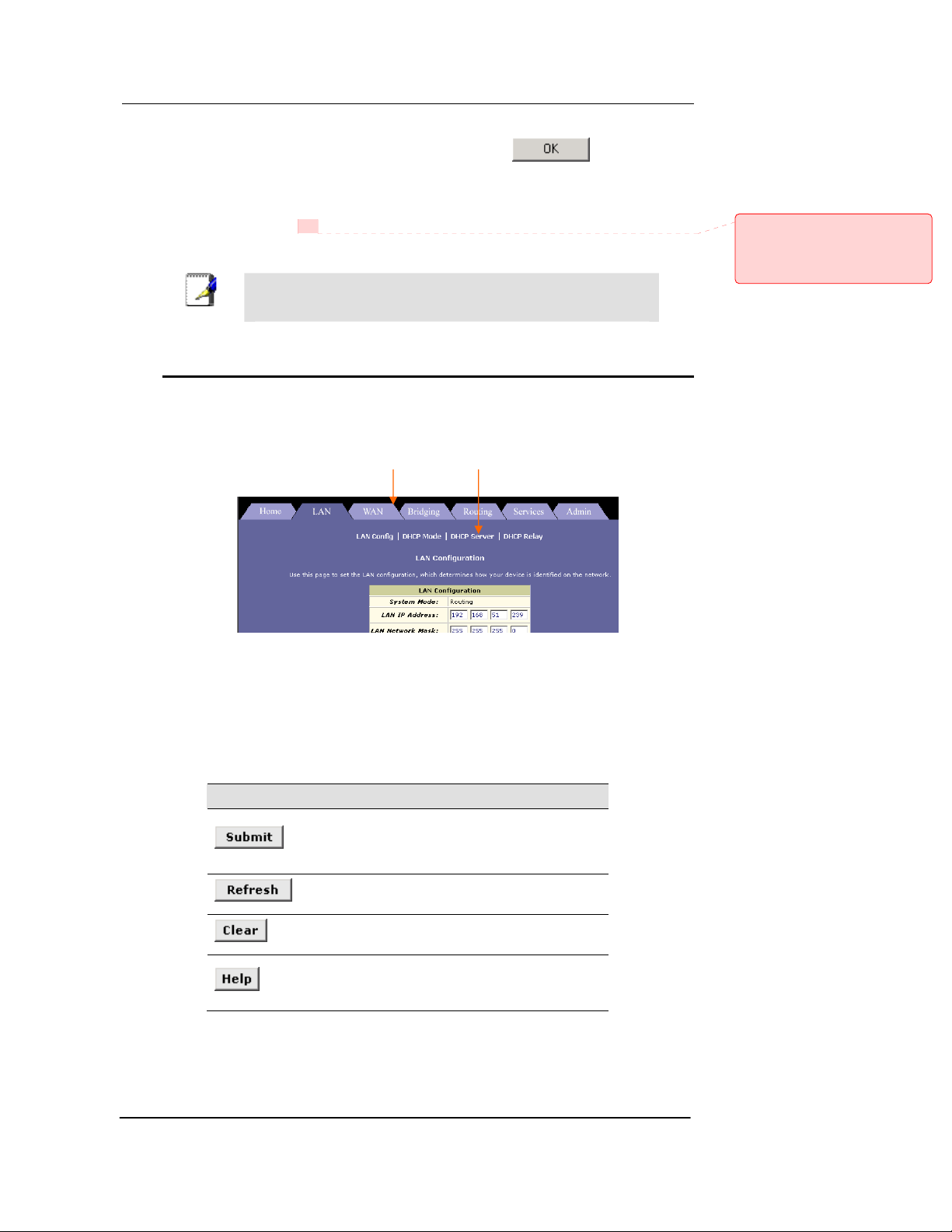
Configuration Manager tasks are grou ped into categorie s, which you can acces s by
clicking the tabs at the top of each page. You can click on these to display the specific
configuration options.
Tab Task bar
Comment [CT4]: Replace with the
default user ID and password that you
preconfigure on your product, if
different. Search for and replace
throughout.
A separate page displays for each task in the task bar. T he left-mo st task disp lays by
default when you click on a new tab. The same task ma y appear in more than one tab,
when appropriate. For example, the Lan Config task displays in both the LAN tab and the
Routing tab.
Commonly used buttons
The following buttons are used throughout the application.
Button Function
Stores in temporary sy stem memory a ny changes y ou
have made on the current pag e. See “ Committing
your changes” on page 17 for instructions on storing
changes permanently.
Redisplays the current page with updated
statistics.
When accumulated statistics are displaying, this
button resets the statistics to their initial value s.
Launches the online help for the current topic in a
separate browser window. Help is available from
any main topic page.
16
Page 25
Best Data DSL542 ADSL Ethernet Router User’s Guide
Changing Your Login Password
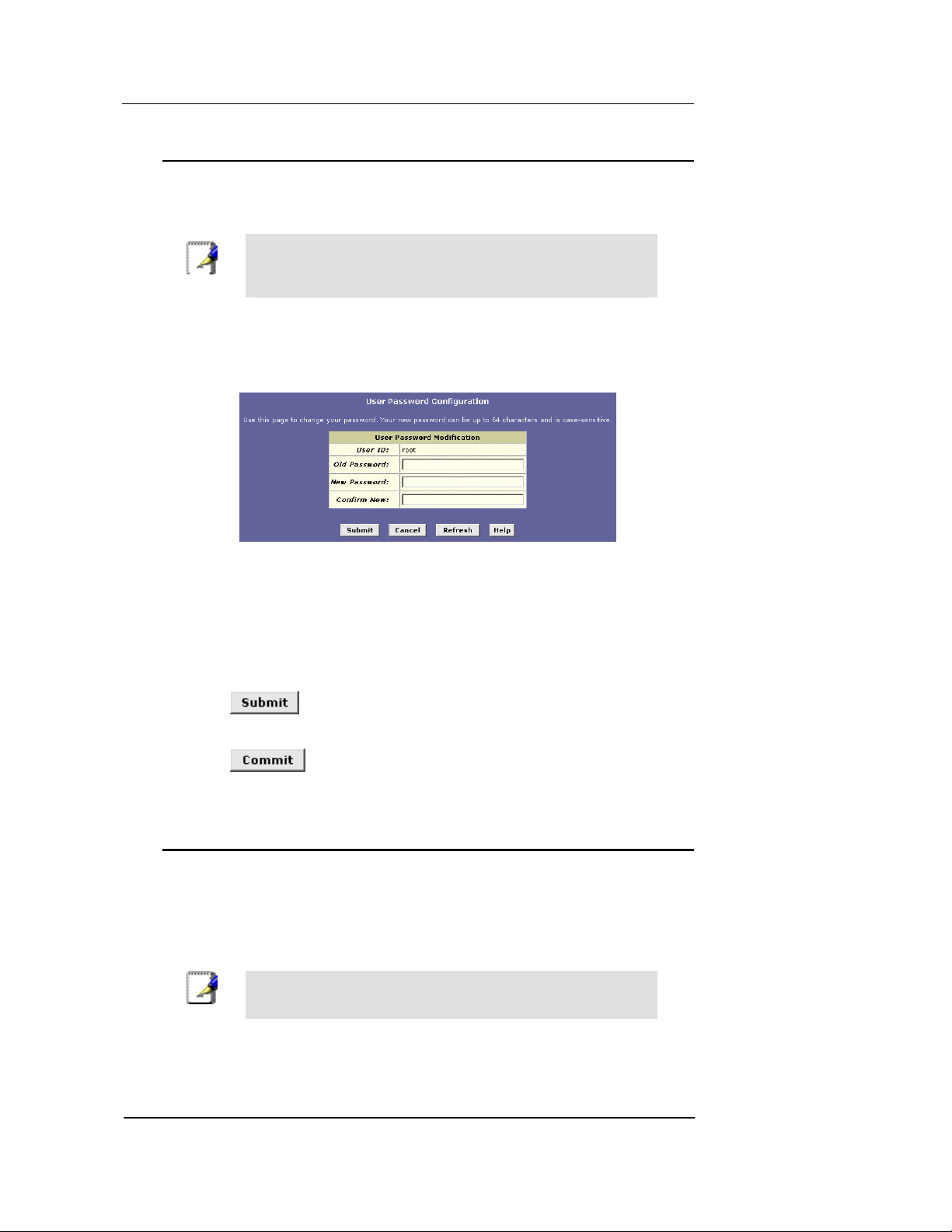
The first time you log into the Configuration Manager, you use the default user ID and
password (root and root). The system allows only one user ID and password. Only the
password can be changed.
This user ID and password is only used for loggin g into the
Configuration Manager; it is not the same as the login you may use
Note
To change the Configuration Manager login password:
1. Click the Admin tab.
The User Password Configuration page displays by default.
2. Type your current password in the Old Password text box.
3. Type the new password in the New Password text box and again in the Confirm
New text box.
The password can be up to eight AS CII char acters long. When logging in, you mu st ty pe
the new password in the same upper and lower case characters that you use here.
to connect to your ISP (described in Chapter 11).
Figure 11. User Password Configuration Page
4. Click
5. Click the Admin tab, and then click
6. Click
.
Commit & Reboot in the task bar.
to save your changes to permanent memory.
Committing Your Changes and Rebooting the Device
Committing your changes
Whenever you use the Configuration Manager to change system settings, the changes are
initially placed in temporary storage. Your changes are made effective when you submit
them, but will be lost if the device is reset or turned o ff.
To save your changes for future use, y ou can us e the commi t function .
Submitting changes saves them only un til the de vice is reset o r
Note
powered do wn. Committing changes saves them permanently.
17
Page 26
Best Data DSL542 ADSL Ethernet Router User’s Guide
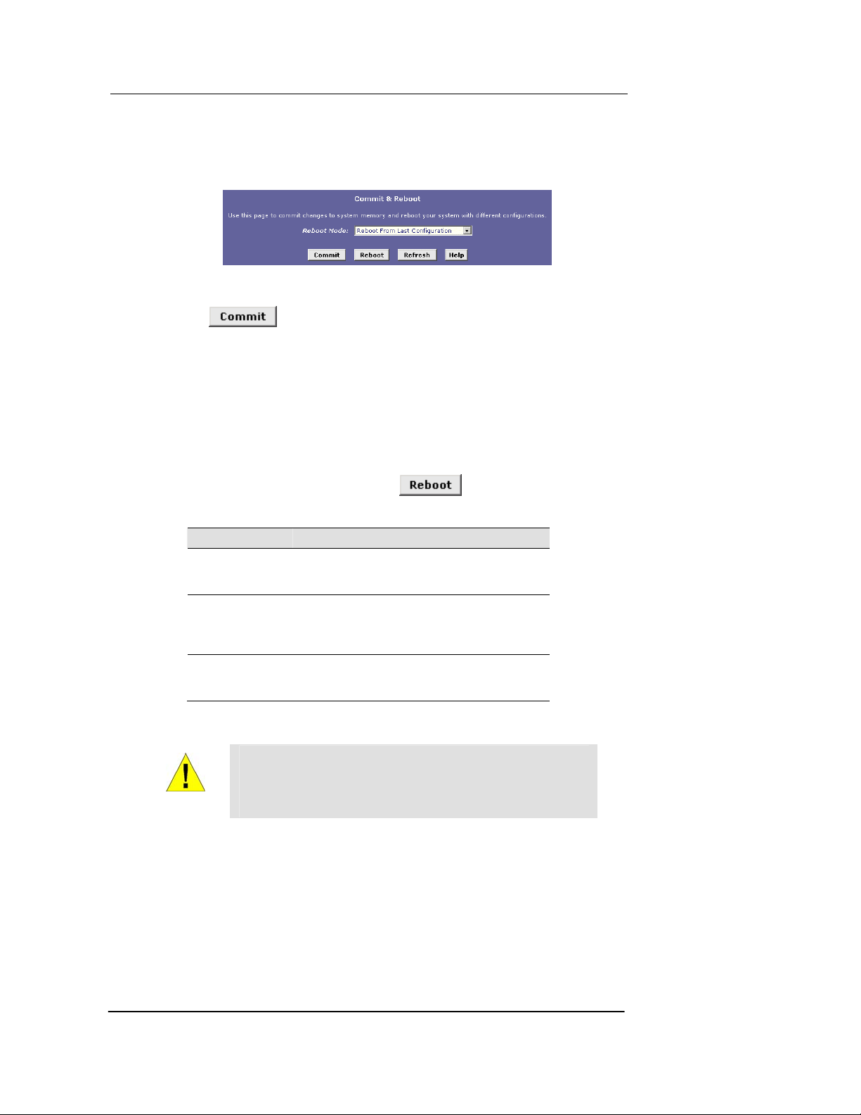
Follow these steps to commit changes to permanent storage .
1. Click the Admin tab, and then click
Commit & Reboot in the task bar.
The Commit & Reboot page displays:
Figure 12. Commit & Reboot Page
2. Click
. (Disregard the selectio n in the Reboot Mode drop-down list; it
does not affect the commit process.)
The changes are saved to permanent storage.
The previous settings are copied to backup storage so that they can be recalled if your new
settings do not work prope rly (see
the rebooting instructions o n page 18) .
Rebooting the device using Configuration Mana ger
To reboot the device, display the Commit and Reboot page, select the appropriate reboot
mode from the drop-down menu, and then click
.
You can select from the following three opt ions when rebooting :
Option Description
Reboot from Last
Configuration
Reboot from Backup
Configuration
Reboot from Default
Configuration
Reboots the device using the current settings in
permanent memory, including any changes you
just committed.
Reboots the device using setting s stored in
backup memory. These are the settin gs that were
in effect before you committed new settings in the
current session.
Reboots the device to default settings prov ided by
your ISP or the manufacturer. Choosing this
option erases any custom setting s.
18
WARNING
Do not reboot the device using the Reset but ton on the back panel
of the Best Data DSL542 to activate new changes. This butto n
resets the device settings to the manufacturer’s default values.
Any custom settings will be lost.
Page 27
Best Data DSL542 ADSL Ethernet Router User’s Guide
5 Setting the LAN IP Address
This chapter describes how to configure the interfaces on the ADSL/Ethernet router that
communicate with your LAN and USB computers.
Ethernet, USB, or Both?
If you are using the ADSL/Ethernet router with multiple PCs on your LAN, you must
connect the LAN via an Ethernet hub to the device's LAN port, called eth-0.
If you are using a single PC with the ADSL/Ethernet router, you have two options for
connecting it to the device:
f You can connect the PC directly to the LAN port using a crossover Ethernet cable.
See Appendix A, “Troubleshooting“ for a description of crossover versus straightthrough Ethernet cables.
f If the PC is USB-enabled, you can connect it directly to the device's USB port,
called usb-0. Only one computer can be connected in this manner.
You can also use the USB and Ethernet ports simultaneously, connecting your LAN to the
Ethernet port and a standalone PC to t he USB port. (U SB port is an o ption)
You must assign a unique IP address to each device p ort that y ou use.
The instructions that follow assume that the device has been
preconfigured to operate in Routing mode, which uses the IP
protocol to determine how to exchange data among your PCs, the
device, and your ISP. If your device i s confi gured in Bridging
Note
mode, its ports do not require IP addresses. The operating mode
displays at the top of the LAN Configuration page and cannot be
changed by the user.
Configuring the LAN IP Address
The LAN IP address identifies the LAN port (eth-0) as a node on your network; that is, its IP
address must be in the same subnet as the PCs on your LAN.
A network node can be thought of as an y interface where a
device connects to the network, suc h as the Best D ata DSL54 2’s
Definition
You can change the default to reflect the set of IP addresses that you want to use with your
network.
If your network uses a local DHCP server (other than the ADSL/Ethernet router) to assign
IP addresses, you can configure the device to accept and use a LAN IP address assigned
by that server. In this mode, the ADSL/Ethernet router is considered a DHCP client of your
DHCP server.
LAN port and the network interface card s on your PCs.
Note
The Best Data DSL542 itself can function as a DHCP server for
your LAN computers, as described in Cha pter 5, but not for its
own LAN port.
19
Page 28
Best Data DSL542 ADSL Ethernet Router User’s Guide
Follow these steps to change the default LAN IP address or to configure the LAN port as a
DHCP client.
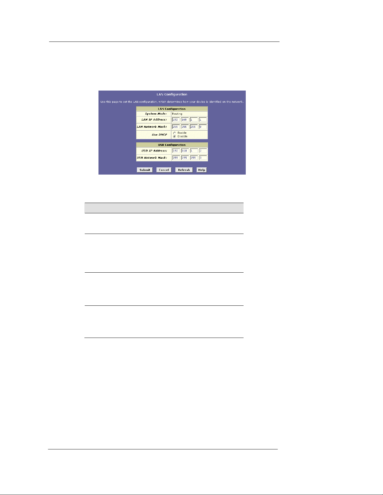
1. Log into Configuration Manager, and then cli ck the LAN tab.
The LAN Configuration page displays, as shown in Figure .
Figure 13. LAN Configuration Page
The LAN Configuration table displays the following settings:
Setting
System Mode
LAN IP
Address
LAN Network
Mask
Use DHCP
Description
The preconfigured mode for your device, such as
Routing or Bridging mode. This setting is not user configurable.
The IP address your computers use to identify the
device’s LAN port.
Note that the public IP addre ss as signe d to y ou by y our
ISP is not your LAN IP address. The pu blic IP address
identifies the WAN (ADSL) port on your ADSL/Ether net
router to the Internet.
The LAN Network mask identifies which parts of the
LAN IP Address refer to y our ne twork as a whol e and
which parts refer specifically to nodes on the network.
Your device is preconfigured with a default network
mask of 255.255.255.0.
When checked, this setting instructs the device to
accept LAN IP information assigned dynamically from
another DHCP server already con figured on your
network. The Best Data DSL542 cannot act as a DHCP
server for its own LAN port.
2. Enter a LAN IP address and networ k mask, or click the DHCP Enable radio
button.
f Entering a fixed address: If you are using routing services on you LAN
such as DHCP and NAT, you will want to assign a fixed LAN IP address an d
mask. This ensures that your LAN computers have a fixed address that they
use to communicate with the device.
The IP address you assign must be on the same subnet as your LAN
computers that connect to this port (th at is, the n etwork ID po rtion of th eir IP
addresses and their subnet masks must be the same).
20
Page 29

Best Data DSL542 ADSL Ethernet Router User’s Guide
You may need to update the DHCP configuration so that the addresses that
the DHCP server dynamically assigns to your comp uters are on the same
subnet as the new LAN IP address. S ee Chapter 6 for inst ructions on
changing the pool of dynamically assigned addresses. In addition, if you
change the DHCP pool, you will also n eed to upda te the NAT c onfigurat ion
so the new IP addresses are translated properly. See Chapter 7 for
instructions on NAT.
f Enabling DHCP: If another computer on your LAN provides DHCP services
for your network, you can click the U se DHCP che ckbox to enable th e LAN
port to accept a dynamically assigned address from the server. Check with
your ISP to determine if this is advi sable.
When you click the Enable radio b utton, t he LAN Ne twork Mask fie ld will be
dimmed (made unavailable for en try ). The LAN IP A ddress field will re main
editable, however. The address th at you spe cify he re will be used a s a
requested IP address from the DHCP server. This is referred to as a
"Configured IP Address" in the program. If the configured IP address is not
available from the DHCP server, the serve r will dis tribute another address to
the LAN port. Even if another number is assigned, the same configured IP
address will continue to display in this fiel d.
For a description of how DHCP works, see Chapter 6.
3. Click
.
f If you were using an Ethernet connection for the current session, and changed
the IP address, the connection will be terminated .
f If you are currently using the USB interface, a page will display to con firm your
change and your connection will re main a ctive.
f If you enabled the DHCP service, the ADSL/Ethernet router will initiate a
request for an IP address from your LAN's DHCP server. Assuming a different
IP address is assigned, your curr ent conne ction wi ll be t erminated .
4. Reconfigure your PCs, if necessary, so that their IP addresses place them in the
same subnet as the new IP address of the LAN port.
5. Log into Configuration Manager by typing the new IP address in your Web
browser’s address/location box.
If you enabled DHCP, you may need to check the DHC P server on your LAN to
determine the IP address actually assigned to the LAN port.
6. If the new settings work properly click the Admin tab, and then click
Reboot
in the task bar.
7. Click
to save your changes to permanent memory.
Commit &
Configuring the USB Port IP Address
1. If the LAN Configuration page is not already displaying, click the LAN tab.
2. In the USB Configuration table, enter the IP Address and Network Mask for the
USB port.
The IP address must place the USB port in the same subnet as the USB computer; If
you are using both the LAN port and the USB port, how ever, the USB port and USB
computer must not be in the same subnet as the LAN port or t he compu ters atta ched to
it.
21
Page 30

Best Data DSL542 ADSL Ethernet Router User’s Guide
For example, you could assign the following IP addresses to the LAN and USB ports
(both assume a network mask of 255.255.255.0):
LAN
USB
Port IP Address
192.168.1.1 192.168.1.x (x = 3-254)
192.168.1.2 192.168.1.x
Computer(s) IP
Address(es)
3. Click
.
f If you are currently communicating with the device via the USB interface, then
the connection will be terminated, be cause th e IP addr ess that the conne ction
was using has now changed.
f If you are currently using the Ethernet interface, a page will display to confir m
your change and your connection will remain active.
4. If necessary, reconfigure your USB PC so that its IP address places it in the same
subnet as the new IP address of the USB port.
5. Log into Configuration Manager by typing the new USB port IP address in your
Web browser’s address/locat i on box.
6. If the new settings work properly click the Admin tab, and then click
Reboot
in the task bar.
7. Click
to save your changes to permanent memory.
Commit &
22
Page 31
Best Data DSL542 ADSL Ethernet Router User’s Guide
6 Configuring Dynamic Host Configuration
Protocol
You can configure your netw ork a nd Best D ata DS L 542 to u se the Dy namic H o st
Configuration Protocol (DHCP). This chapter provides DHCP instructions for implementing
it on your network.
The device can be configured as a DHCP server, DHCP relay agent, or, in some cases, a
DHCP client.
You can input settings for both DHCP server and DHCP relay
mode, and then activate either mode at any time. De-activated
Note
Configuring DHCP Server
Note
First, you must configure your PCs to accept DHCP information assigned by a DHCP
server:
1. Open the Windows Control Panel and display the c omputer's Networking
properties. Configure the TCP/IP properties to "Obtain an IP address
automatically" (the actual text may vary depending on your operating system).
Next, you define the pools of IP addres ses y ou want to make ava ilable for distrib ution
to your computers. These addresses can b e multiple public a ddresse s that y ou have
purchased from your ISP, but are typically private addresses that you create. (LAN
administrators often create private IP addresses for use only on their networks.
2. Log into Configuration Manager, click the LAN tab, and t hen click
the task bar.
settings are retained for your future u se.
By default, the device is configured as a D HCP server, wi th a
predefined IP address pool of 192.168.1.2 through 192.168.1.13
(subnet mask 255.255.255.0). To change this range of
addresses, see “Viewing, modifying, and deleting address
pools” on page 25.
DHCP Server in
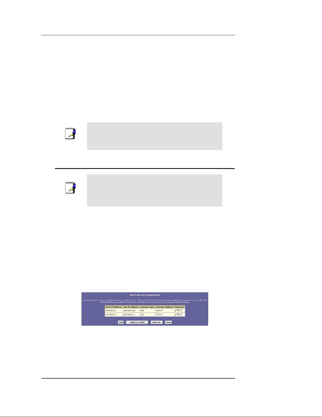
The DHCP Server Configuration page displays, as shown in Figure 15.
Each pool you create displays in a row on the table on this page.
You can create up to eight pools ; howeve r, most u sers will need to crea te only one f or their
LAN. Some users many want to create another that distributes an IP address to their USB
computer, which must be in a different subnet than the LAN computers.
Figure 14. DHCP Configuration Page
23
Page 32
Best Data DSL542 ADSL Ethernet Router User’s Guide
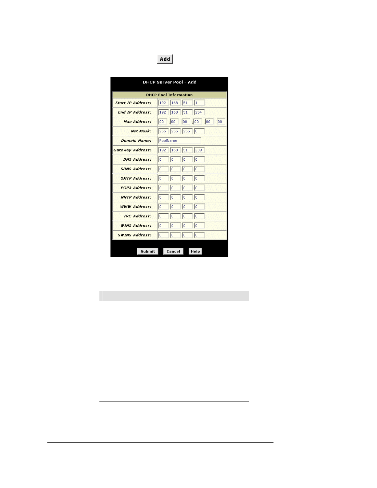
3. To add an IP address pool, click .
The DHCP Server Pool – Add page displays, as shown in Figure 16.
Figure 15. DHCP Server Pool – Add Page
4. Enter the Start IP Address, End IP Address, Net Mask, and Gateway Address
fields are required; the other s ar e optio nal . Th e fol l o win g tabl e describes each
field.
Field Description
Start/End IP
Addresses
Mac Address
Specify the lowest and highest addresses
in the pool.
Use this field only if you want to ass ign a
specific IP address to a specific compu ter
(that is, you are creating an exception to
the dynamic assignment of addresses).
The IP address you specify will be
assigned to the computer that
corresponds to this MAC address. (A MAC
address is a manufacturer-assigned
hardware ID that is unique for each device
on a network.) If you type a MAC address
here, you must have specified the sam e IP
address in both the Start IP Address and
End IP Address fields.
24
Page 33

Best Data DSL542 ADSL Ethernet Router User’s Guide
Field Description
Net Mask
Specifies which portion of each IP address
in this range refers to the network and
which portion refers to the host
(computer). You can use the network
mask to distinguish which pool of
addresses should be distributed to a
particular subset of computers on your
LAN (called a subnet).
Domain Name
A user-friendly name that refers to the
group of computers (subnet) that will be
assigned addresses from this pool.
Gateway
Address
The address of the default gateway for
computers that receive IP addresses from
this pool. The default gateway is the IP
address that the computers first contact to
communicate with the Internet. Typically, it
is the device’s LAN port IP address.
DNS/SDNS
Address
The IP address of the Domain Name
System server and Secondary Domain
Name System server to be used by
computers that receive IP addresses from
this pool. These DNS servers translate
common Internet names that you type into
your web browser into their equivalent
numeric IP addresses. Typic ally , the se
servers are located with your ISP.
SMTP...SWINS
(optional)
The IP addresses of devices that pe rform
various services for computers that
receive IP addresses from this pool (su ch
as the SMTP, or Simple Mail Transfer
Protocol, server which handles e-mail
traffic). Contact your ISP for these
addresses.
5. Click .
A confirmation page displays briefly to in dicate th at the poo l has been add ed
successfully. After a few seconds, the DHCP Server Pool – Add page displays with the
newly added pool.
6. Follow the instructions in “Setting the DHCP Mode” on page 28 to set the DHCP
mode to DHCP Server.
Viewing, modifying, and deleting address pools, and excluding IP addresses from a
pool
To view, modify, or delete an existing address pool, display the DHCP Server Configuration
page, and click the icons in the corresponding row in the address pool table.
f To delete an IP address pool, click
f To view details on an IP address pool, click
, then submit and commit your changes .
. A page displays with all the same
information you entered when adding the pool.
To modify the domain name associate d with an IP address pool, or to exc lude
addresses from the pool, click
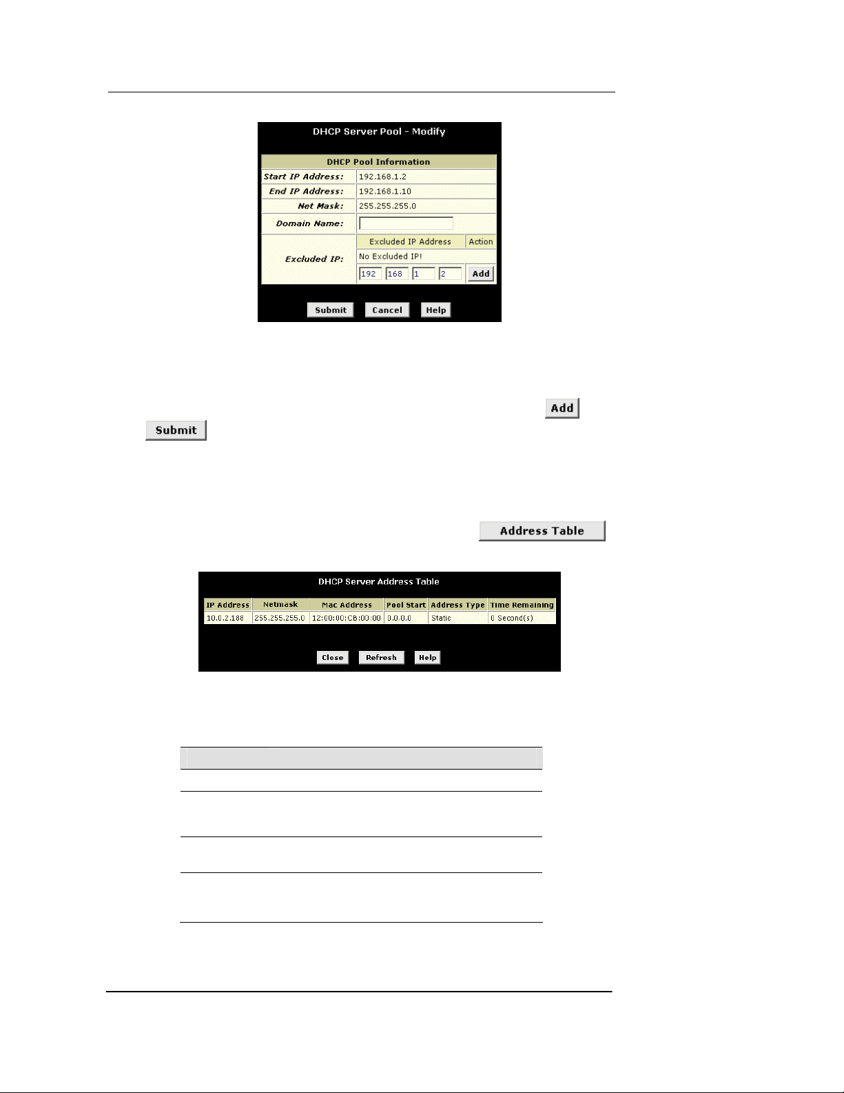
. The DHCP Server Pool – Modify page displays,
as shown in Figure .
25
Page 34
Best Data DSL542 ADSL Ethernet Router User’s Guide
Figure 16. DHCP Server Pool – Modi fy Pa ge
Excluded addresses are those that you have designated for fixed use with specific devices,
or for some other reason do not want to make available to your network.
To exclude an address from distribution, type it in t he field s provided and click
. Click
after entering your changes. Be sure to use the Commit feature to save your
changes to permanent memory, as described on page 17.
Viewing current DHCP address assignments
When the Best Data DSL542 functions as a DHCP server for your LAN, it keeps a record
of any addresses it has leased to your computers. To view a table of all current IP address
assignments,
display the DHCP Server Configuration page, click .
A page displays similar to that shown in Figure :
Figure 17. DHCP Server Address Table Page
The DHCP Server Address Table lists any IP addresses that are currently leased to LAN
devices. For each leased address, th e table lists the follow ing information :
Field Description
IP Address
Netmask
The address that has been leased from the pool.
The network mask associated with the leased address,
which identifies the network ID and host ID por tions of
the address (see Appendix A).
Mac Address A hardware ID for the device to which th e numbe r
has been assigned.
Pool Start The lower boundary of the address pool
(provided to identify the pool from which the
leased number came).
26
Page 35
Best Data DSL542 ADSL Ethernet Router User’s Guide
Field Description
Address Type
Static or Dynamic. Static indicates that the IP
number has been assigned permanently to the
specific hardware device. Dynamic indicates that
the number has been leased temporarily for a
specified length of time.
Time
Remaining
The amount of time left for the device to u se the
assigned address.
Configuring DHCP Relay
Some ISPs perform the DHCP server function for their customers’ home/small office
networks. In this case, you can configure the device as a DHCP relay agent. When a
computer on your network requests Internet access, the Best Data DSL542 contacts your
ISP to obtain an IP address (and othe r information) , and then forwards that inform ation to
the computer.
First, you must configure your PCs to accept DHCP information assigned by a DHCP
server:
1. Open the Windows Control Panel and display the computer's Networking
properties. Configure the TCP/IP properties to "Obtain an IP address
automatically" (the actual text may vary depending on your operating system).
Next, you specify the IP address of the DHCP server and select the interfaces on
your network that will be using the relay service.
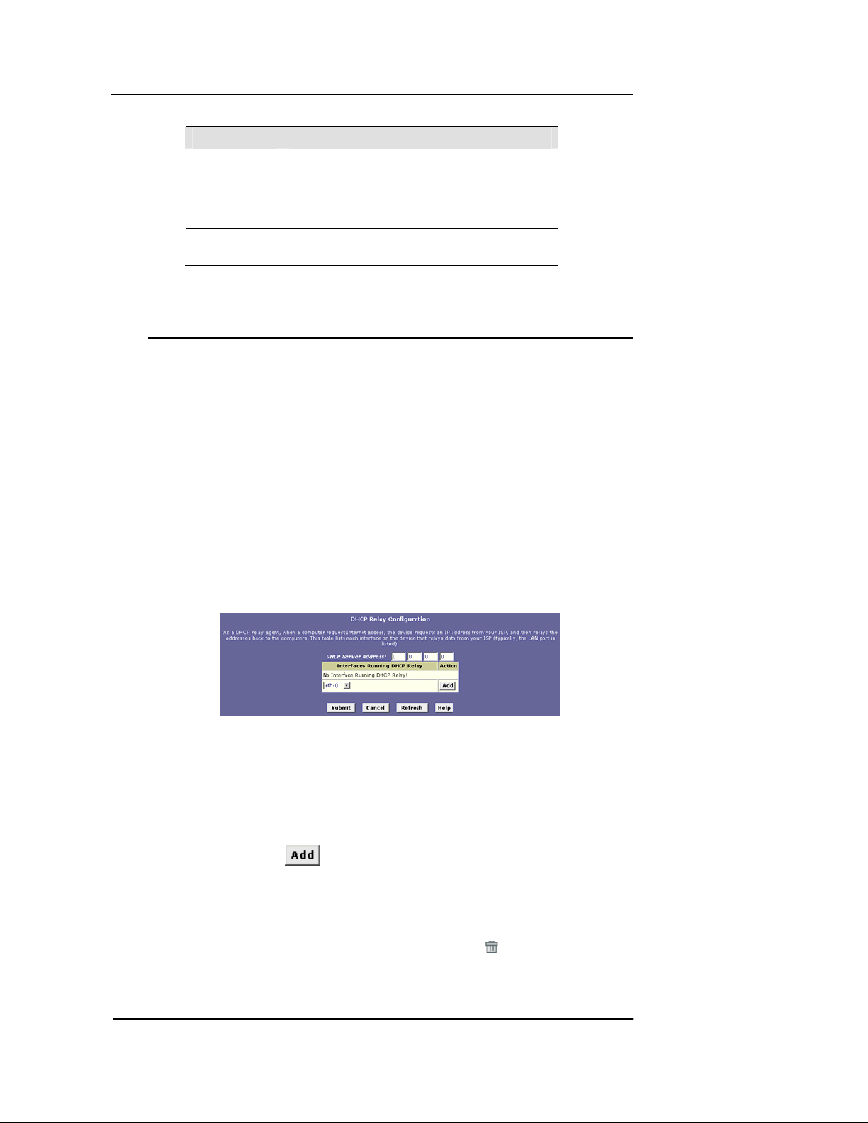
2. Log into the Configuration Manager, click the LAN tab, and then click
in the task bar.
The DHCP Relay Configuration page displays, as shown in Figure 19.
DHCP Relay
Figure 18. DHCP Relay Configuration Page
3. Type the IP address of your ISP’s DHCP server in the fields provided.
If you do not have this number, it is not es sential to enter it h ere. Reque sts for IP
information from your LAN will be pas sed to the default g ateway , which shou ld rou te
the request appropriately.
4. If the interface named eth-0 is not already dis playing, select it from the dropdown list and click
.
The eth-0 interface specifies that your default Ethernet (LAN) interface is running
DHCP relay for your LAN. Typically, this is the only interface you need to specify here.
If the Best Data DSL542 has additional interfaces that you want to perform DHCP
relay, you can select and add them.
(You can also delete an interface from the table by clicking
in the right column.)
27
Page 36

Best Data DSL542 ADSL Ethernet Router User’s Guide
5. Click .
A page displays to confirm your changes, and then the program returns to the DHCP
Relay Configuration page.
6. Follow the instructions in “Setting the DHCP Mode” on page 28 to set the DHCP
mode to DHCP Relay.
Setting the DHCP Mode
You should set the DHCP mode only after you have configured DHCP relay or DHCP
server settings. See “Configuring DHCP Server” on page 23 or “Configuring DHCP Relay”
on page 27 for additional instruction s.
Follow these instructions to set the DHCP mode:
1. Click the LAN tab, and then click DHCP Mode in the task bar.
2. From the DHCP Mode drop-down list, choose DHCP Server, DHCP Relay, or
none.
If you choose none, your LAN compute rs must be configu red w ith static I P
addresses.
3. Click
.
4. Click the Admin tab, and then click Commit & Reboot in the task bar.
5. Click
to save your changes to permanent memory.
28
Page 37
Best Data DSL542 ADSL Ethernet Router User’s Guide
7 Configuring Network Address Translation
This chapter provides Network Address Translation (NAT) instructions for modifying the
default configuration on your device.
Your Default NAT Setup
By default, NAT is enabled, with a napt rule configured to perform the following translation:
These private IP addresses: ...are translated to:
192.168.1.3
192.168.1.4
.
.
.
192.168.1.34
For a description of napt rules, see page 33. This default NAT setup assumes that, on each
LAN computer, you configured TCP/IP prope rties as follo w s:
f You selected the check box that enables them to receive their IP addresses
automatically (that is, to use a DHCP server);
or,
f You assigned static IP addresses to your PCs in the range 192.168.1.3 through
192.168.1.34.
If your computers are not configured in on e of the se ways , you can either change the IP
addresses on your computers to match the NAT se tup or dele te this NAT rule and add a new
one that matches the addresses y ou assigned to your compu ters (see “Adding NAT Rule s” on
page 33 for instructions).
Your ISP-assigned
public IP address
Viewing NAT Global Settings and Statistics
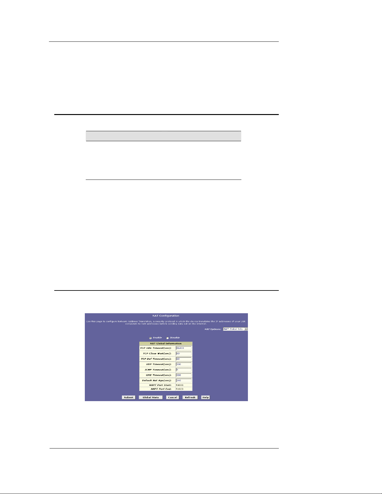
To view your NAT settings, log into Con figuration Manager , click th e Servic es tab . The NAT
Configuration page displays by default, as shown in Figure .
Figure 19. NAT Configuration Page
29
Page 38

Best Data DSL542 ADSL Ethernet Router User’s Guide
The NAT Configuration page contains the following elements:
f The NAT Options drop-down list, which provides access to the Global Information page
(shown by default), the NAT Rule Config uration page , and the NAT Transla tions pag e,
which shows current translations.
f Enable/Disable radio buttons, which allow you to turn on or off the NAT feature.
f The NAT Global Information table, which displays the following settings that apply to all
NAT rule translations:
Field Description
TCP Idle Timeout (sec)
TCP Close Wait (sec)
TCP Def Ti me o u t (s ec)
UDP Timeout (sec)
ICMP Timeout (sec)
GRE Timeout (sec)
Default Nat Age (sec)
NAPT Port Start/End
For a NAT translation session on data that
uses the TCP protocol, the translation will
no longer be performed if no matchi ng da ta
packets are received after the specified
time has elapsed.
For a NAT translation on data using the
TCP protocol, after a communication
session has been closed, the translation
will no longer be performed if n o matching
data packets are received after the
specified time has elapsed.
For a NAT translation session on data that
uses the TCP protocol, the translation will
no longer be performed if no matchi ng da ta
packets are received after the specified
time has elapsed.
Same as TCP Idle Timeout, but for UDP
packets.
Same as TCP Idle Timeout, but for ICMP
packets.
Same as TCP Idle Timeout, but for GRE
packets.
For all other NAT translation sessions, the
number of seconds after which a
translation session will no lo nger b e valid .
When a napt rule is defined, the source
ports will be transl ated to sequ e ntia l
numbers in this range.
If you change any values, click
, and then click the Admin tab and commit your
changes to permanent system memory ( see page 17) .
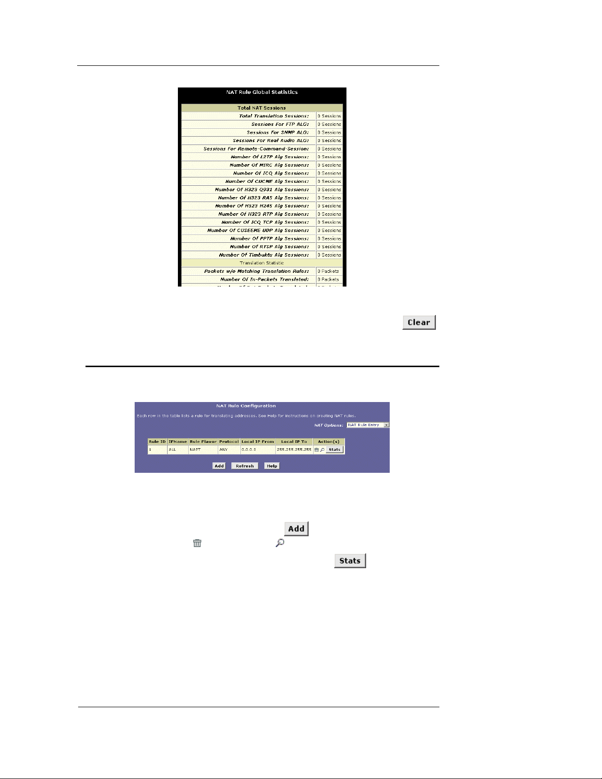
You can click
to view accumulated data on how m any NAT rule s have
been invoked and how much data ha s been tran slated . A page similar to the one is s hown in
Figure displays.
30
Page 39
Best Data DSL542 ADSL Ethernet Router User’s Guide
Figure 20. NAT Rule Global Statistics Page
The table provides basic information for each NAT rule you have set up. You can click
to restart the accumulation of the statistics at their initial values.
Viewing NAT Rules and Rule Statistics
To view the NAT rules currently defined on your sy stem, se lect NAT Rule Entry in the NAT
Options drop-down list. The NAT Rule Co nfiguration page di splay s, as shown in Figure .
The NAT Rule Configuration table displays a row containing basic information for each rule. For
a description of these fields, refer to the instru ctions for ad ding rules (pag es 33 through 39).
From the NAT Rule Configuration page, you can click
in the right column to delete (
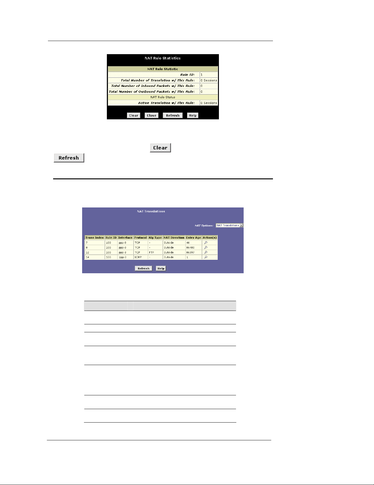
To view data on how often a specific NAT rule has been used, click
column. A page similar to the one show in Figure displays:
Figure 21. NAT Rule Configuration Page
to add a new rule, or use the icons
) or view details on ( ) a rule.
in the Action(s)
31
Page 40
Best Data DSL542 ADSL Ethernet Router User’s Guide
Figure 22. NAT Rule Statistics Page
The statistics show how many times this rule has been invoked and how many currently active
sessions are using this rule. You can click
to reset the statistics to zeros and
to display newly accumulated data.
Viewing Current NAT Translations
To view a list of NAT translations that have recently been performed and which remain in effect
(for any of the defined rules), select NAT Translations from the NAT Options drop-down list.
The NAT Translations page display s, as shown in Figure :
Figure 23. NAT Translations Page
For each current NAT translation session, the table contains the following fields:
Field Description
Trans Index
Rule ID
Interface
Protocol
Alg Type
NAT Direction
Entry Age
The sequential number assigned to the IP
session used by this NAT translation session.
The ID of the NAT rule invoked.
The device interface on which the NAT rule was
invoked (from the rule definition).
The IP protocol used by the data packets tha t
are undergoing translations (from the rule
definition) Example: TCP, UDP, ICMP.
The Application Level Gateway (ALG), if any,
that was used to enable this NAT translation
(ALGs are special settings that certain
applications require in orde r to wo rk while NA T is
enabled).
The direction (incoming or outgoing) of the
translation (from the port definition).
The elapsed time, in seconds, of the NAT
translation session.
32
Page 41
Best Data DSL542 ADSL Ethernet Router User’s Guide
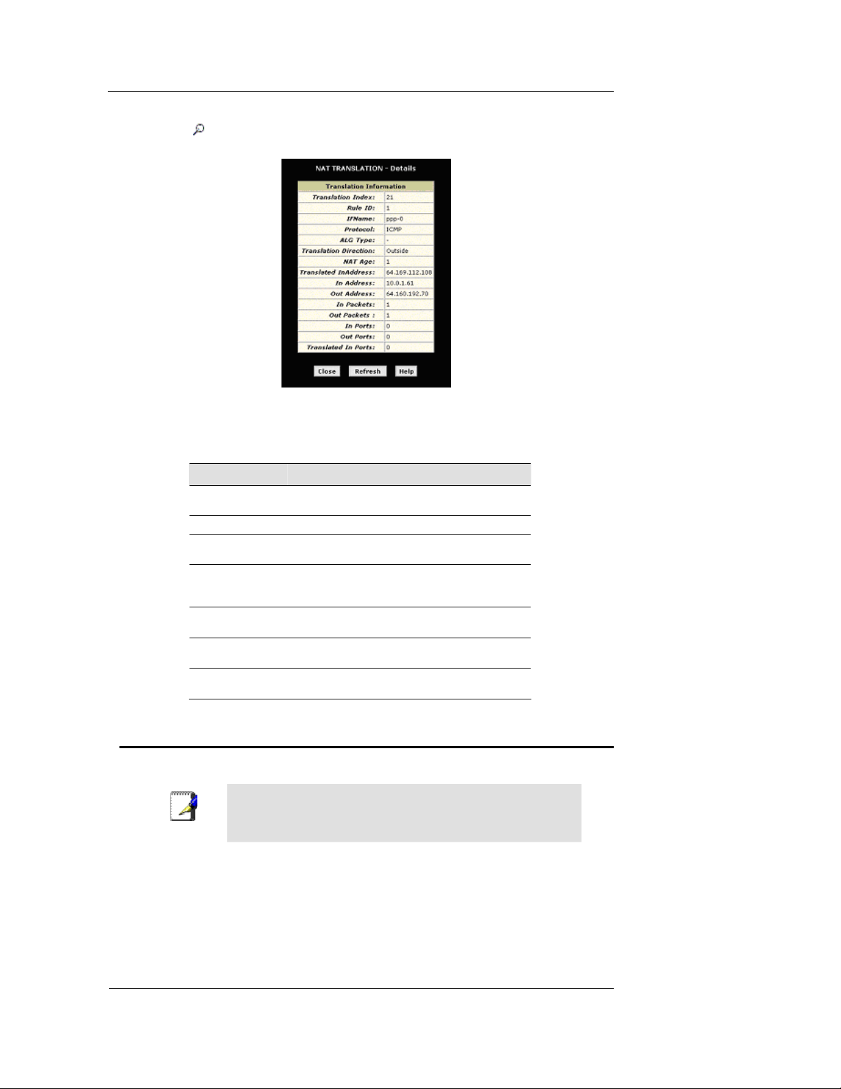
You can click in the Action(s) column to view additional details abou t a NAT tran slation
session, as shown in Figure .
Figure 24. NAT Translation – Detai ls Pa ge
In addition to the information disp layed in the NAT Tr anslation s table, t his table display s the
following for the selected current translatio n session s:
Field Description
Translated
InAddress
In Address
Out Address
In/Out Packe ts
In Ports
Out Ports
Translated In Ports
The public IP address to which the private IP
address was translated.
The private IP address that was translated.
The IP address of the outside destination (web,
ftp site, etc.)
The number of incoming and outg oing IP
packets that have been tra nslate d in thi s
translation session.
The actual port number correspondin g to the
LAN computer.
The port number associated with the destination
address.
The port number to which the LAN computer’s
actual port number was translated.
Adding NAT Rules
This section explains how to create rules for the various NAT flavors.
You cannot edit existing NAT rules. To change a rule setup,
Note
The napt rule: Translating between p rivate and pub lic IP addresses
Follow these instructions to crea te a rule f or transla ting the pr ivate IP addresses on y our LAN to
your public IP address. This type of r ule uses the NAT fla vor napt, wh ich was u sed in y our
default configuration. The napt flavor translates private source IP addresses to a single public IP
address. The napt rule also translate s the sou rce port nu mbers to port numbers that are defin ed
on the NAT Global Configuration page (see pa ge 29).
delete it and add a new rule with the modified settings.
33
Page 42
Best Data DSL542 ADSL Ethernet Router User’s Guide
Click the NAT tab, then select NAT Rule Entry from the NAT Option s drop-dow n list on the
right side of the page.
The NAT Rule entry page displays a row for each currently configured NAT rule.
1. Click
to display the NAT Rule – Add page.
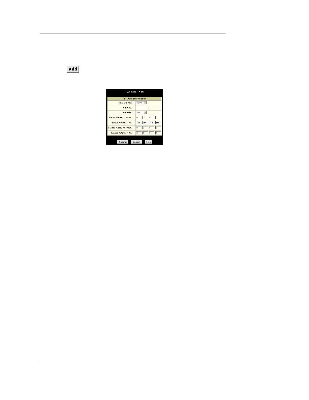
The NAPT flavor displays by default in the Rule Flavor drop-down list. The NAT Rule – Add
page displays, as shown in Figure .
Figure 25. NAT Rule – Add Page (napt Flavor )
2. Enter a Rule ID.
The Rule ID determines the order in which rules are invoked (the lowest numbered rule is
invoked first, and so on). In some cases, two or more rule s may be defined to act on the
same set of IP addresses. Be sure to assign t he Rule ID so that the h igher priority ru les
are invoked before lower-priority rules. It is recommended that you select rule IDs as
multiples of 5 or 10 so that, in the future, you can insert a rule between two existing rules.
Once a data packet matches a rule, the data is acted upon according to that rule and is
not subjected to higher-numbered rules.
3. From the IFName drop-down list, select the interface on the de vi c e to which this ru le
applies.
Typically, NAT rules are used for communication between your LAN and the Internet.
Because the device uses the WAN interface (which may be named ppp-0 or eoa-0) to
connect your LAN to your ISP, it is the usual IFName selection.
4. In the Local Address From field and Local Address To fields, type the starting and
ending IP addresses, respectively, of
the range of private address you want to be
translated. Or, type the same address in both fields to specify a single value.
To specify that data from all LAN addresse s should be transla ted, ty pe 0 (zero) in each
From field and 255 in each To field.
If you have several non-sequential private ad dresses , you ca n create an additiona l napt
rule for each address.
These addresses should correspond to private addresses already in use on your network
(either assigned statically to your PCs, or assigned dynamically using DHCP).
5. In the Global Address From and Global Address To fields, type the public IP address
assigned to you by your ISP.
If you have multiple WAN interfaces, in both fie lds type the IP addres s of the in terface to
which this rule applies. This rule w ill not be enforced for data that ar rives on othe r PPP
interfaces.
If you have multiple WAN interfaces and want the rule to be enforced on a range of them,
type the starting and ending IP addre sses o f the range.
34
Page 43
Best Data DSL542 ADSL Ethernet Router User’s Guide
6. When you have completed entering all information, click .
A page displays to confirm the change.
7. Click
to return to the NAT Configuration page.
The new rule should display in the NAT Rule Configuration table.
8. Ensure that the Enable radio button is selected, and then click
.
A page displays to confirm y our change s.
9. Click the Admin tab, and then click
10. Click
to save your changes to permanent memory.
Commit and Reboot in the task bar.
The rdr rule: Allowing external access to a LAN computer
You can create an rdr rule to make a computer on your LAN, such as a Web or FTP server,
available to Internet users without requiring you to obtain a public IP address for that computer.
The computer’s private IP address is translated to your public IP address in all incoming and
outgoing data packets.
Without an rdr rule (or bimap rule described on page 39 ), the Best
Data DSL542 blocks attempts by external computers to access
Note
your LAN computers.
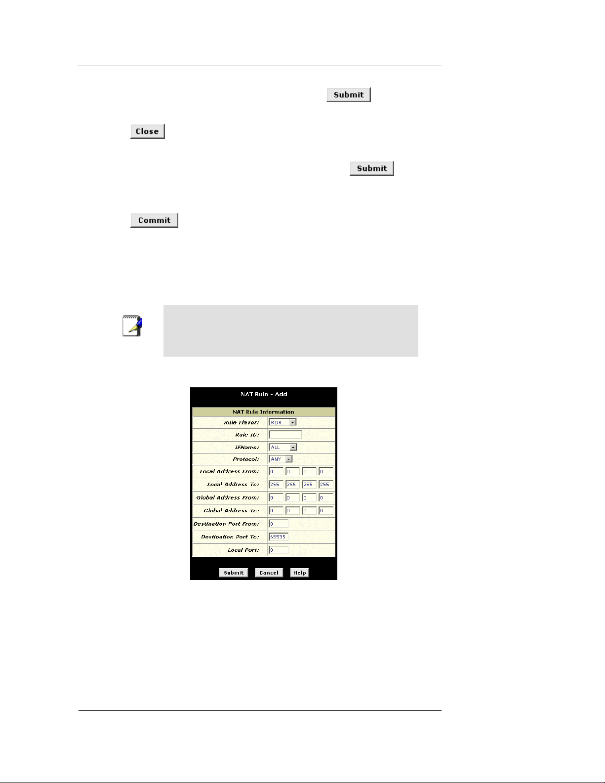
Figure shows the fields used to establish a rdr rule:
Figure 26. NAT Rule – A dd Pa ge (rdr Flavor)
Follow these instructions to add an rdr rule (see steps 1-4 under "The napt rule" on page 33 for
specific instructions corresponding to steps 1 and 2 below):
1. Display the NAT Rule – Add Page, select RDR as the Rule Flavor, and enter a Rule
ID.
2. Select the interface on which this rule will be effective.
35
Page 44

Best Data DSL542 ADSL Ethernet Router User’s Guide
3. Select a protocol to which this rule applies, or choo se ALL.
This selection specifies which ty pe of Interne t communica tion wi ll be subjec t to this
translation rule. You can select ALL if the ru le applie s to all data. Or , select TCP , UDP,
ICMP, or a number from 1-255 that represents the IANA-specified protocol number.
4. In the Local Address From and Local Address To fields, type the same private IP
address, or the lowest and highest addresses in a range:
f If you type the same IP address in both fields, incoming traffic that matches the
criteria you specify in steps 5 and 6 w ill be redirect ed to that IP address .
f If you type a range of addresses, incoming traffic will be redirect ed to any available
computer in that range. This option w ould ty pically be used for load balan cing,
whereby traffic is distributed among several redundant servers to help ensure
efficient network performance.
These addresses should correspond to private addresses already in use on your network
(either assigned statically to your PCs or assigned dynamically using DHCP).
5. In the Global Address From and Global Address To fields, type the public IP address
assigned to you by your ISP.
If you have multiple WAN (PPP) interfaces, this rule will not be enforced for data that
arrives on other PPP interfaces. This rule w ill not b e enforced for data that a rrives o n
WAN interfaces not specified here.
If you have multiple WAN interfaces and w ant the rule to be enfo rced on mo re than
one of them (or all), type the starting and ending IP addresses of the range.
6. In the Destination Port From and Destination Port To fields, enter the port ID (or a
range) that you expect to see on incoming packets destined for the LAN computer for
which this rule is being created.
Incoming traffic that meets this criter ia will be redirect ed to the Loca l Port numb er you
specify in the next field.
For example, if you grant public acce ss to a We b server on your LAN , you w ould expec t
that incoming packets destined for that computer would contain the well-known web
server port number, 80. This setting serves as a filter; data packets not containing this port
number would not be granted access to y ou local compu ter.
7. If the LAN computer that you are making publicly available is configured to use a nonstandard port number for the type of traffic it receives, type the non-standard port
number in the Local Port field.
This option translates the standard port number in packets destined for your LAN computer
to the non-standard number you specify. For ex ample, if y our Web server uses (nonstandard) port 2000, but you expect incoming data packet s to refer to (standard ) port 80,
you would enter 2000 here and 80 in the Destination Port fields. The headers of incoming
packets destined for port 80 will be modified to refer to port 2 000. The packet can th en be
routed appropriately to the web server.
8. Follow steps 7-12 under "The napt rule" on page 33 to submit your changes.
The basic rule: Performing 1:1 translations
The basic flavor translates the private (LAN-side) IP address to a public (WAN-side) address,
like napt rules. However, unlike napt rules, basic rules do not also translate the port numbers in
the packet header; they are passed through un translated . Theref ore, the ba sic rule does not
provide the same level of security as the napt rule. Figure shows the fields used for adding a
basic rule.
36
Page 45
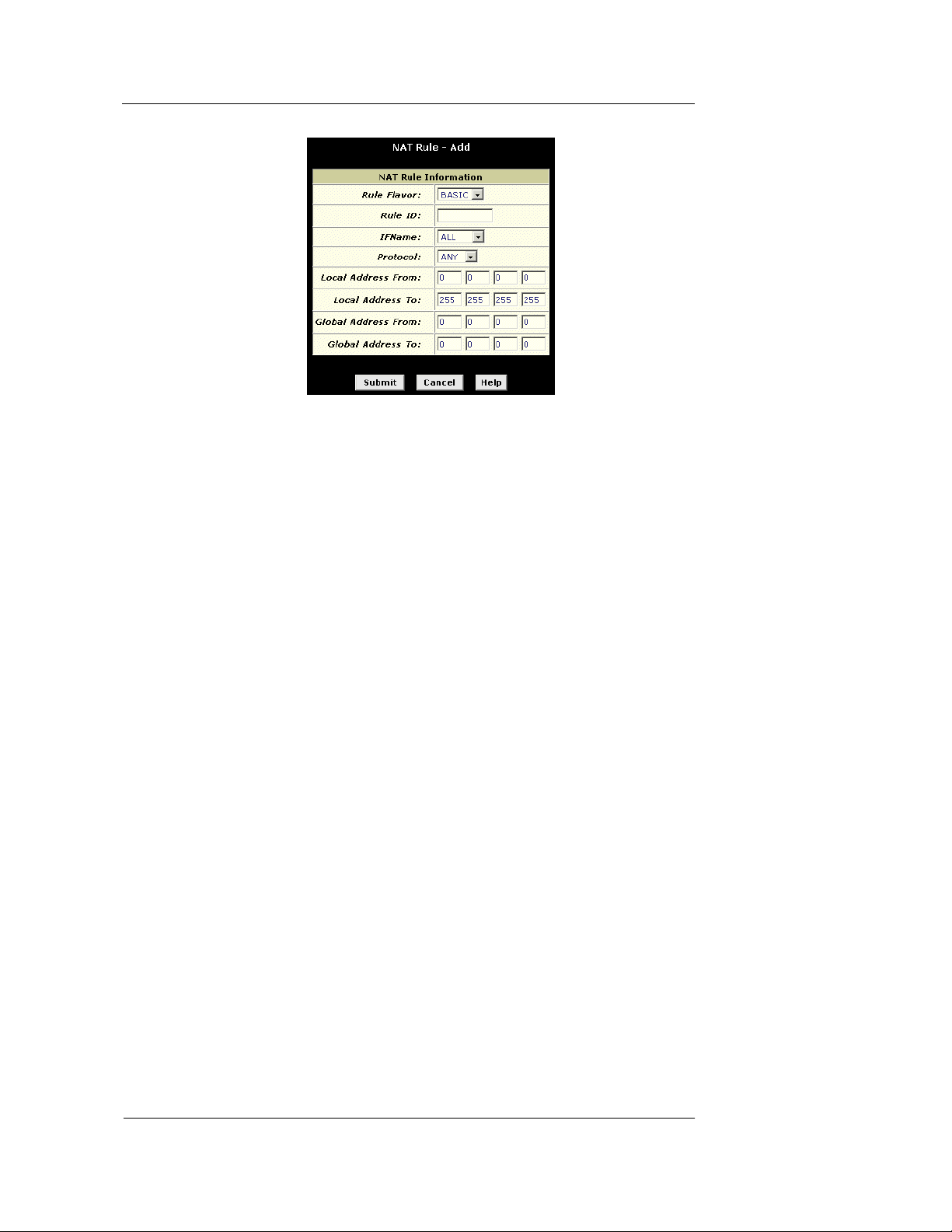
Best Data DSL542 ADSL Ethernet Router User’s Guide
Figure 27. NAT Rule – Add Page (basic Flavor)
Follow these instructions to add an basic rule (see steps 1-4 under "The napt rule" on page 33
for specific instructions correspond ing to step s 1 an d 2 below ):
1. Display the NAT Rule – Add Page, select BASIC as the Rule Flavor, and enter a Rule
ID.
2. Select the interface on which this rule will be effective.
3. Select a protocol to which this rule applies, or choo se ALL.
This selection specifies which ty pe of Interne t communica tion wi ll be subjec t to this
translation rule. You can select ALL if the ru le applie s to all data. Or , select TCP , UDP,
ICMP, or a number from 1-255 that represents the IANA-specified protocol number.
4. In the Local Address From and Local Address To fields , type the starting and ending
IP addresses that identify the range of private address you want to be translated. Or,
type the same address in both fields.
If you specify a range, each addres s w ill be tra nslated in sequen ce to a corre sponding
address in a range of global addresses (which you specify in step 5).
You can create a basic rule for each specific a ddres s transla tion to oc cur. The r ange of
addresses should correspond to private addresses already in use on your network,
whether assigned statically to your PCs, or assigned dynamically using DHCP.
5. In the Global Address From and Global Address To fields, type the starting and
ending address that id entify the pool of public IP addresses that the private addresses
should be translated to. Or, type the same address in bot h fields (if you also specified
a single address in step 4).
6. Follow steps 7-12 under "The napt rule" on page 33 to submit your changes.
The filter rule: Configuring a basic rule with additional criteria
Like the basic flavor, the filter flavor translates public and private IP addresses on a one-to-one
basis. The filter flavor extends the capab ility of the basic rule. Refe r to “The basic Rule” o n page
36 for a general description.
You can use the filter rule if you want an address translation to occur only when your LAN
computers initiate access to specific destinations . The destinations can be identified by their
IP addresses, server t ype (such as FTP or Web server) , or both. Figure shows the fields
used to establish a filter rule.
37
Page 46
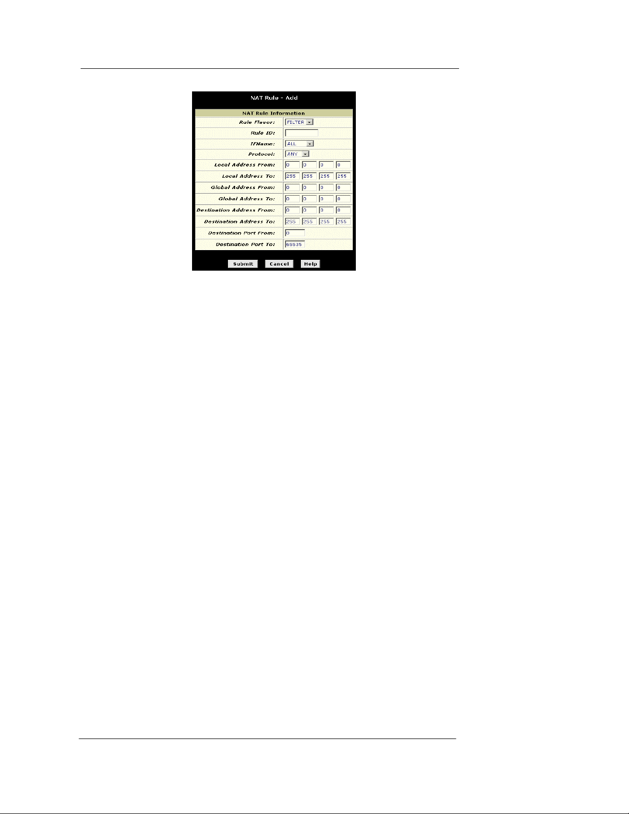
Best Data DSL542 ADSL Ethernet Router User’s Guide
Figure 28. NAT Rule⎯Add Page (filter Flavor)
Follow these instructions to add a filter rule (see steps 1-4 under "The napt rule" on page 33 for
specific instructions corresponding to steps 1 and 2 below):
1. Display the NAT Rule – Add Page, select FILTER as the Rule Flavor, and enter a
Rule ID.
2. Select the interface on which this rule will be effective.
3. Select a protocol to which this rule applies, or choo se ALL.
This selection specifies which ty pe of Interne t communica tion will b e subjec t to this
translation rule. You can select ALL if the ru le applie s to all data. Or , select TCP , UDP,
ICMP, or a number from 1-255 that represents the IANA-specified protocol number.
4. In the Local Address From and Local Address To fields , type the starting and ending
IP addresses that identify the range of private address you want to be translated. Or,
type the same address in both fields.
If you specify a range, each addres s w ill be tra nslated in sequen ce to a corre sponding
address in a range of global addresses (which you specify in step 5).
The address (or range of addresses) should correspond to a private addresses (or
addresses) already in use on your network. These may be assigned statically to your PCs
or assigned dynamically using DHCP.
5. In the Global Address From and Global Address To fields, type the starting and
ending address that identify the range of public IP addresses to translate your private
addresses to. Or, type the same address in both fields (if you also specified a single
address in step 4).
6. Specify a Destination Address or addresses, Destination Port (or ports), or both. You
can specify a single value by entering that value in both fields.
f Specify a destination address (or range) if you want this rule to apply only to outbound
traffic to the address (or range).
If you enter only the network ID portion of the d estination addre ss, then the rule w ill
apply to outbound traffic to all computers on network.
f Specify a destination ports (or range) if you wan t this rul e to apply to any outbound
traffic to the types of servers identified by that port number.
Port number assignments are maintained in RFCs maintained by IANA. Common
port numbers include:
20, 21—FTP (file transfer protocol) ser ver
25—SMTP (simple mail transfer protocol) server
80—HTTP (World Wide Web) server
38
Page 47
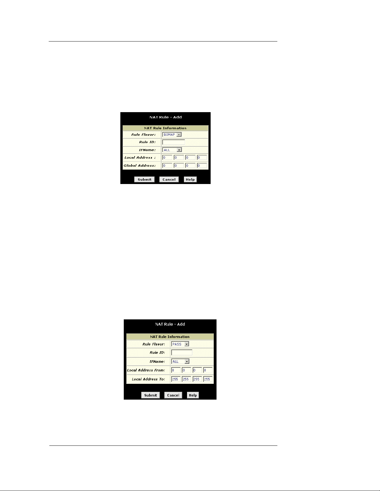
Best Data DSL542 ADSL Ethernet Router User’s Guide
f Specify both a destination address (or range) and a destin ation port (o r range) if you
want this translation rule to apply to accesses to the specified server type at the
specified IP address or network.
7. Follow steps 7-12 under "The napt rule" on page 33 to submit your changes.
The bimap rule: Performing two-way translations
Unlike the other NAT flavors, the bimap flavor performs address translations in both the
outgoing and incoming directions. Figure shows the fields used to establish a bimap rule.
Figure 29. NAT Rule – Add Page (bimap F lavor)
Follow these instructions to add a bimap rule (see steps 1-4 under "The napt rule" on page 33
for specific instructions correspond ing to step s 1 an d 2 below ):
1. Display the NAT Rule – Add Page, select BIMAP as the Rule Flavor, and enter a
Rule ID.
2. Select the interface on which this rule will be effective.
3. In the Local Address field, type the private IP address of the computer to which you
are granting external access.
4. In the Global Address field, type the address that you want to serve as the publicly
known address for the LAN computer.
5. Follow steps 7-12 under "The napt rule" on page 33 to submit your changes.
The pass rule: Allowing specific addresses to pass through untranslated
You can create a pass rule to allow a range of IP addresses to remain untranslated when
another rule would otherwise do so.
Figure 30. NAT Rule – Add Page (pass Flav or)
The pass rule must be assigned a rule ID that is a lower number than the ID assigned to the
rule it is intended to pass. In you want a specific IP address or range of addresses to not be
39
Page 48

Best Data DSL542 ADSL Ethernet Router User’s Guide
subject to an existing rule, say rule ID #5, then you ca n create a pass rule w ith ID # 1 through
#4.
Follow these instructions to add a pass rule (see step s 1-4 und er "The napt rule" on page 33 for
detailed instructions corresponding to steps 1 and 2 below):
1. Display the NAT Rule – Add Page, select PASS as the Rule Flavor, and enter a Rule
ID.
2. Select the interface on which this rule will be effective.
3. In the Local Address From and Local Address To fields, type the lowest and highest
IP addresses that define the range of private address you want to be passed without
translation.
If you want the pass rule to act on only one address, type that address in both fields.
4. Follow steps 7-12 under "The napt rule" on page 33 to submit your changes.
40
Page 49
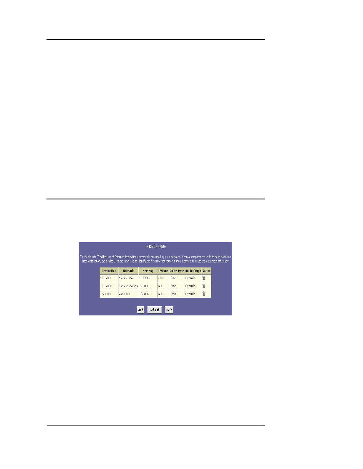
Best Data DSL542 ADSL Ethernet Router User’s Guide
8 Configuring IP Routes
You can use Configuration Manager to d efine spe cific routes for your Internet and netw ork data.
This chapter provides instructions for creating routes.
Most users do not need to define IP routes. On a ty pical small h ome or off ice LAN, the existin g
routes that set up the default gateway s for your LAN c omputers an d for the Best D ata DSL5 42
provide the most appropriate path for all your Internet traffic.
f On your LAN computers, a default gateway directs all Internet t raffic to the LAN port on
the Best Data DSL542. Your LAN computers know their def ault gatew ay eithe r because
you assigned it to them when you modified their TCP/IP properties, or because you
configured them to receive the information dynamically from a server whenever they
access the Internet.
f On the Best Data DSL542 itself, a default gateway is defined to direct all outbound
Internet traffic to a router at your ISP. This default gatew ay is assigne d automati cally by
your ISP whenever the device negotiate s an Int ernet co nnection.
You may need to define routes if your ho me setup include s two or more network s or subnet s, if
you connect to two or more ISP services, or if you connect to a rem ote corpor ate LAN.
Viewing the IP Routing Table
All IP-enabled computers and routers maintain a table of IP addresses that are commonly
accessed by their users. For each of th ese destin ation I P addresse s, the tab le lists the IP addre ss
of the first hop the data should take. This table is known as the device’s routing table.
To view the Best Data DSL542’s routing tab le, click th e Routing tab. The IP Route Ta ble disp lays,
as shown in Figure 32.
The IP Route Table displays a row for each existing route. These include routes that were
predefined on the device, routes you may have added, and routes that the device has identified
automatically through communication with other devices.
The routing table should reflect a default gateway, which directs outbound Internet traffic to your
ISP. This default gateway is show n in the row contain ing destin ation ad dress 0.0.0 .0.
The following table defines the fields in the IP R outing Ta ble.
Figure 31. IP Route Table Page
41
Page 50
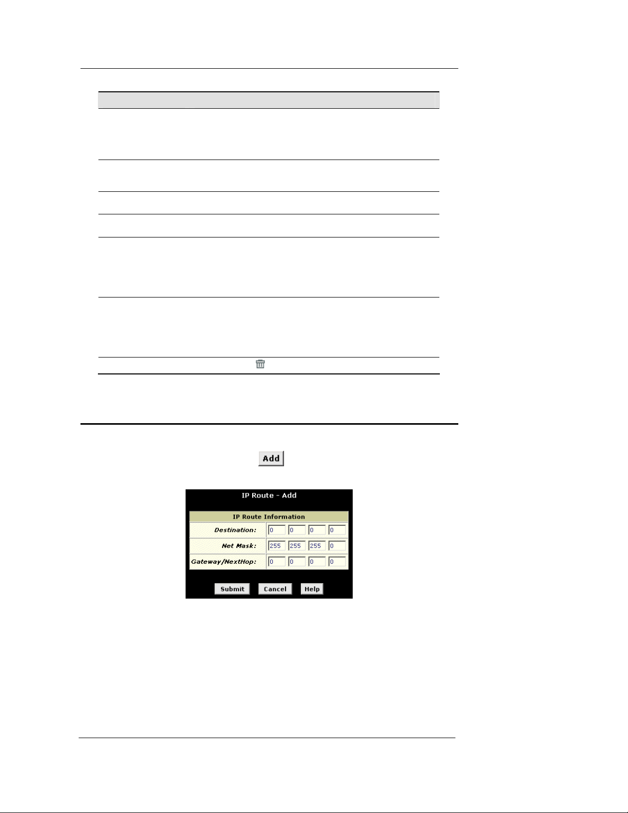
Best Data DSL542 ADSL Ethernet Router User’s Guide
Field Description
Destination
Netmask
NextHop
IFName
Route Type
Route Origin
Action
Specifies the IP address of the destination computer. The des tinatio n
can specified as the IP address of a speci fic comp uter or an en tire
network. It can also be specified as all zeros to indicate that this route
should be used for all destinatio ns for whi ch no o ther rou te is define d
(this is the route that creates the defaul t g atewa y ).
Indicates which parts of the destination address refer to the network
and which parts refer to a computer on the ne two rk. The de fault
gateway uses a netmask of 0 .0. 0.0.
Specifies the next IP address to send da ta to w h en its fi nal de st in ati on
is that shown in the destination column.
Displays the name of the interface on the de vice through which data is
forwarded to the specified next hop.
Displays whether the route is direct or indirect. In a direct route, the
source and destination compute rs are o n the same networ k, and the
router attempts to directly deliver the da ta to the compu ter. In a n
indirect route, the source and destination computers are on different
networks, and the router forwards data to a device on another network
for further handling.
Displays how the route was defined. Dynamic indicates that the route
was created automatically or predefined by your ISP or the
manufacturer. Routes you create are labeled Local. Other routes can
be created automatically (usin g RIP, as de scrib ed in Ch apter 8 ), or
defined remotely through various network management protocols
(LCL or ICMP).
Displays an icon (
) you can click on to delete a route.
Adding IP Routes
Follow these instructions to add an IP route to the routing table.
1. From the IP Route Table page, click
The IP Route – Add page displays, as shown in Figure 33.
Figure 32. IP Route – Add Page
2. Specify the destination, network mask, and gateway or next hop for this route.
To create a route that defines the default gateway for your LAN, enter 0.0.0.0 in both the
Destination and Net Mask fields. Enter your ISP’s IP address in the Gateway/NextHop field.
Note that you cannot specify the interface name, route type or route origin. These parameters
are used only for routes that are identified automatically as the device communicates with
other routing devices. For routes you create, the routing table displays system default values
in these fields.
.
42
Page 51

3. Click .
Best Data DSL542 ADSL Ethernet Router User’s Guide
4. On the confirmation page, click
The IP Routing Table will now disp lay the new route .
5. Click the Admin tab, and then click
6. Click
to save your changes to permanent memory.
Commit & Reboot in the task bar.
to return to the IP Route table page.
43
Page 52
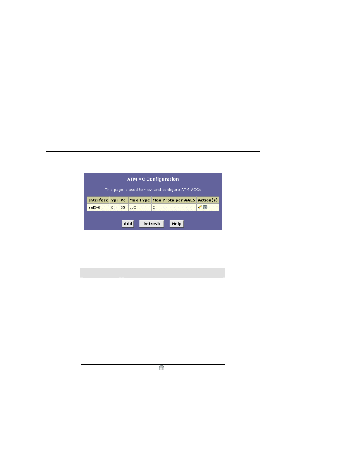
Best Data DSL542 ADSL Ethernet Router User’s Guide
9 Configuring the A TM VCC
As your LAN computers access the Interne t via the Best Da ta DSL542, da ta is ex changed with
your ISP through a complex network of teleph one sw itches , Internet ro uters, se rvers, and other
specialized hardware. These various devices communicate using a common language, or
protocol, called Asynchronous Transfer Mode (ATM). On the Wide Area Network (WAN) that
connects you to your ISP, the ATM protocol performs functions like those that the Ethernet
protocol performs on your LAN.
This chapter describes how to configure the ATM virtual channel connection (VCC). The VCC
properties define the path the Best Data DSL542 uses to communicate with your ISP over the
ATM network.
Viewing Your ATM VC Setup
To view your current configuration, log into Configuration Manager, click the WAN tab, and then
click
ATM VCC in the task bar. The ATM VCC Configuration page displays, as shown in Figure 34.
Figure 33. ATM VCC Configuration Page
The ATM VCC Configuration table displays the following fields (contact your ISP to determine
these settings):
Field Description
Interface
Vpi, Vci, and Mux
Type
Max Proto per
AAL5
Actions
The name of the lower-l evel inte rface on wh ich
this VC operates. The low-level interface names
are preconfigured in the softwa re an d iden tify the
type of traffic that can be supported , such as data
or voice. Internet data services typically use an
AAL5-type interface.
These settings identify a unique ATM data path for
communication between your ADSL/Ethernet
router and your ISP.
If you are using an AAL5-type of interface, this
setting indicates the number of higher-level
interfaces that the VC can support (the higher
level interfaces can be PPP, EoA, or IPoA
interfaces). Contact your ISP to de termine which
connection protocol(s) they require.
Displays an icon (
the associated interface.
) you can click on to delete
44
Page 53
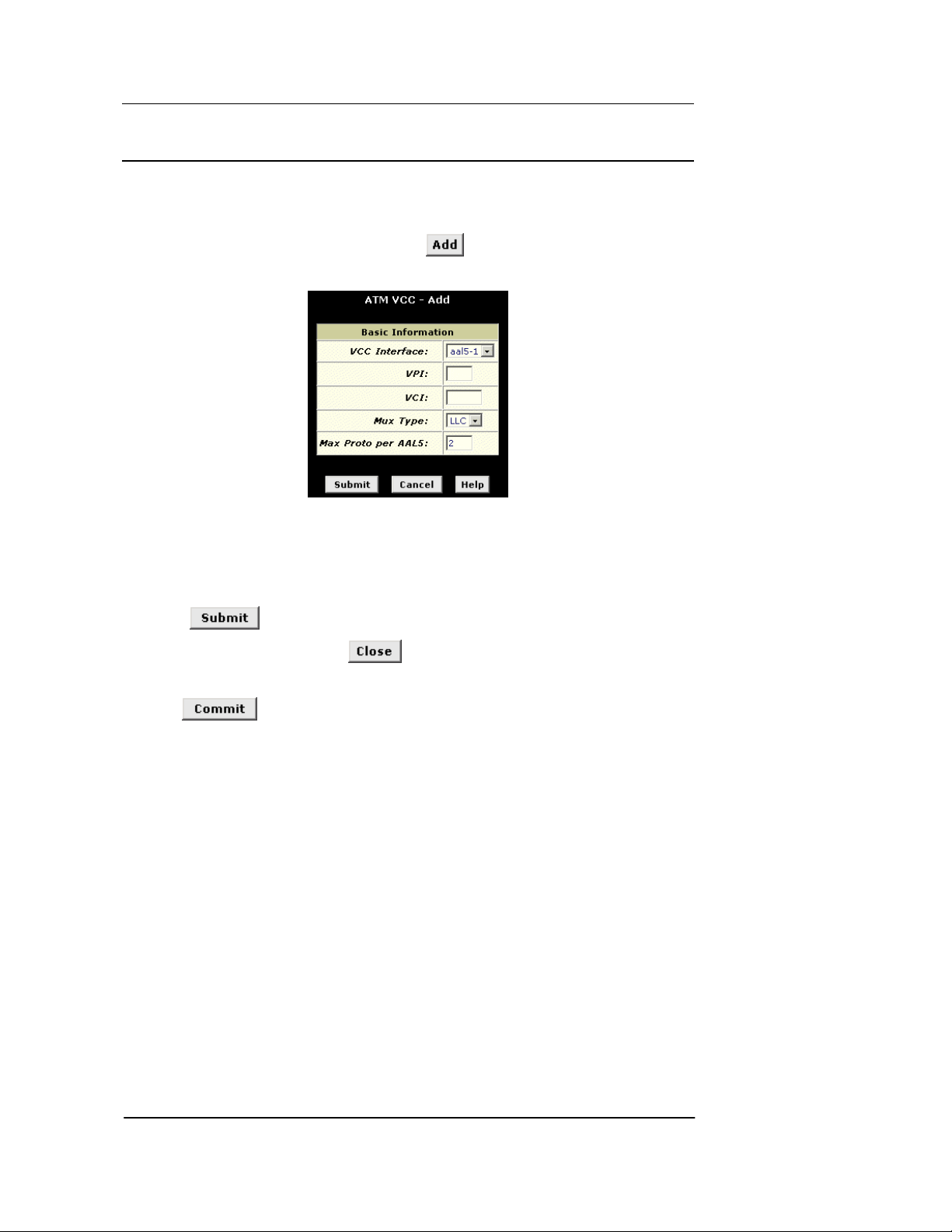
Best Data DSL542 ADSL Ethernet Router User’s Guide
Adding ATM VCCs
You may need to create a VCC if none has be en predef ined on y our system o r if you us e multiple
services with your ISP. Each service may require its own VCC. Follow these instructions to add a
VCC:
1. From the ATM VCC Configuration page, click
.
The ATM VCC – Add page displays, as shown in Figure 35
Figure 34. ATM VCC – Add Page
2. Select an interface name from the VCC Interface drop-down list.
3. Enter the VPI and VCI values assigned by your ISP, and select the mux type from the
drop-down list.
4. Click
5. On the confirmation page, click
6. Click the Admin tab, and then click
.
to return to the ATM VCC Configuration page.
Commit & Reboot in the task bar.
7. Click
to save your changes to permanent memory.
The new interface should now display in the ATM VCC Configuration table.
You may need to create a new WAN inter face, or m odify an existing in terface, so that it uses the
new VCC. See the instructions for configuring a PPP (Chapter 10), EoA (Chapter 11), or IPoA
(Chapter 12) interfaces, depending on the type y ou use to communic ate wit h your ISP.
You can verify that the new settings work by attempting to acce ss the Interne t from a LAN /USB
computer. Contact your ISP for troubleshooting assistance.
45
Page 54
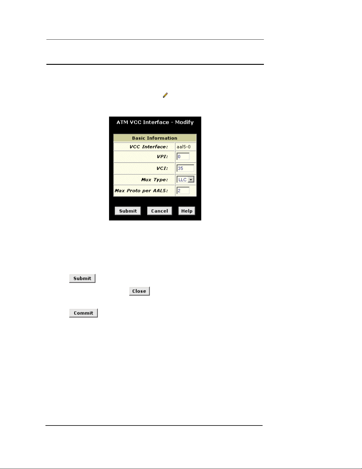
Best Data DSL542 ADSL Ethernet Router User’s Guide
Modifying ATM VCCs
Your device may already be preconfigured with the ne cessary ATM VCC properti es, or the table
may contain placeholder values that you must change before using the device. Contact your ISP
to determine your ATM VCC values. Follow these instructions to modify a preconfigured VCC:
1. From the ATM VCC Configuration page, click in the Actions column for the interface
you want to modify.
The ATM VCC Interface – Modify page displays, as shown in Figure 36.
Figure 35. ATM VCC Interface – Mo dify Page
2. Enter the new VPI and VCI values, select the MUX type, or change the maximum number
of protocols that the VCC can carry, as directed by your ISP.
You cannot modify the interface type over which an existing VCC operates (aal5-0, for
example). If you want to change the interface type, you must delete the existing interface,
create a new one, and select the desired interface type.
3. Click
4. On the confirmation page, click
5. Click the Admin tab, and then click
6. Click
.
to return to the ATM VCC Configuration page.
Commit & Reboot in the task bar.
to save your changes to permanent memory.
7. You can verify that the new settings work by attempting to access the Internet from a
LAN/USB computer. Contact you r IS P for tr oubleshooting assistance.
46
Page 55
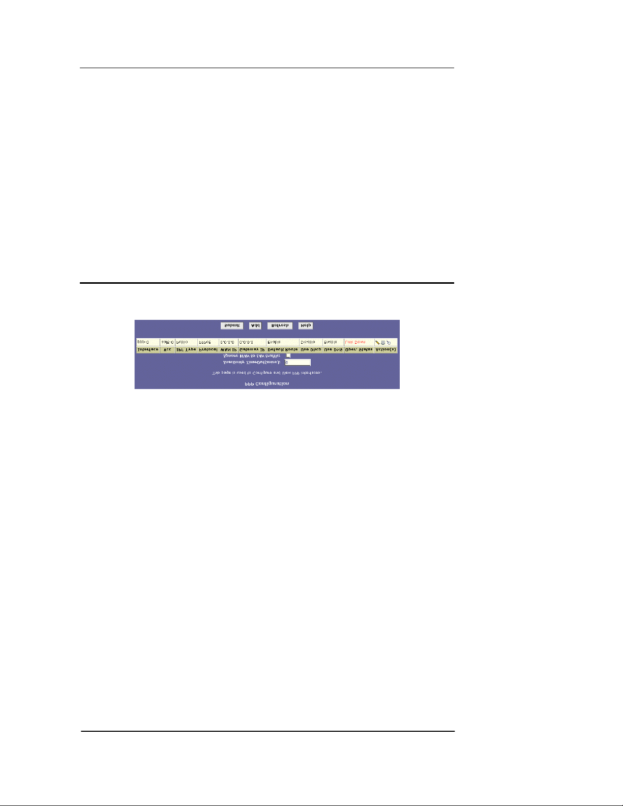
Best Data DSL542 ADSL Ethernet Router User’s Guide
10 Configuring PPP Interfaces
When powered on, the Best Data DSL542 initiates a connection through your DSL line to your
ISP.
The point-to-point (PPP) protocol is commonly used between ISPs and their customers to identify
and control various communication propert ies, inc luding:
f Identifying the type of service the ISP provides to a given customer
f Identifying the customer to the ISP through a username and password login
f Enabling the ISP to assign Internet information to the cu stomer’s computer s
Your ISP may or may not use the PPP protocol. Con tact y our ISP to de termine if y ou will need to
change the default settings in order to connect to their s erver.
Viewing Your Current PPP Configuration
To view your current PPP setup, log into Configuration Manager, click the WAN tab, and then click
PPP in the task bar. The PPP Configuration page displays, as shown in Figure 37.
PPP is configured as a group of software settings a ssoc iated with th e ADSL por t. Altho ugh the
device has only one physical ADSL port, t he Best Data D SL542 can be define d with more than
one group of PPP settings. Each group of settings is called a PPP interface and is given a name,
such as ppp-0, ppp-1, etc.
You can configure the following settings on the PPP Configuration page:
f Inactivity TimeOut (mins): The time in minutes that must elapse before a PPP
connection times-out due to inactivity.
f Ignore WAN to LAN traffic: When enab led, data traffic travelin g in the in coming
direction—from the WAN port to the LAN po rt—will not coun t as activi ty on the WAN port;
i.e., it will not prevent the connectio n from be ing term inated if in active for the spe cified
time.
Figure 36. PPP Configuration Page
47
Page 56

Best Data DSL542 ADSL Ethernet Router User’s Guide
The PPP Configuration Table displays the follo wing fields:
Field Description
Interface
VCC
IPF Type
Protocol
WAN IP
Gateway IP
Default Route
Use DHCP
User DNS
Oper. Status
Actions
The predefined name of the PPP interface.
The Virtual Channel Connection over which this PPP
data is sent. The VCC identifies the phy sical path the
data takes to reach your ISP.
The type of IP Firewall protections that are in effect on
the interface (public, private, or DMZ):
A public interface connects to the Internet (PPP
interfaces are typically public). Packets received on a
public interface are subject to the most restrictive set
of firewall p r o te c ti o ns d e fi n e d in the softwa r e.
A private interface connects to your LAN, such
as the Ethernet interface. Packets received on a
private interface are subject to a less restrictive set of
protections, because they originate within the
network.
The term DMZ (de-militarized zone), in Internet
networking terms, refers to computers that are
available for both public and in-netwo rk accesses
(such as a company's public Web server). Packets
incoming on a DMZ interface -- whether from a LAN
or external source -- are subject to a set of protections
that is in between public and private interface s in
terms of restrictiveness.
The type of PPP protocol used. You r ISP may use
PPP-over-Ethernet (PPoE) or PPP-over-ATM
(PPoA).
The IP address currently assigned to your WAN
(DSL) port by your ISP.
The IP address of the server at your ISP that provides
you access to the Internet.
Indicates whether the ADSL/Ethernet router should
use the IP address assigned to this connection as its
default route. Can be Enab led or Disabl ed .
When set to Enable, the device will acquire additional
IP information from the ISP's DHCP server. The PPP
connection itself acquires the device 's IP address,
mask, DNS address, and default gateway address.
With Use DHCP enabled, the device will acquire IP
addresses for various other server types (WINS,
SMTP, POP3, etc. -- these server types are listed on
the DHCP Server Configurati on pag e).
When set to Enable, the DNS address learned
through the PPP connection will be distrib uted to
clients of the device's DHCP server. This option is
useful only when the ADSL /Eth ernet R ou ter is
configured to act as a DHCP Server for y our LAN.
When set to Disable, LAN hosts will use the DNS
address(es) preconfigured in the DHCP pool (see
“Configuring DHCP Server” on page 23)
Indicates whether the link is currently u p or down or if
a specific type of data exchange is under way (e.g.,
password authorization or DHCP).
You can use these icons to modify (
and view additional details on (
), delete ( ),
) the PPP interface.
48
Page 57
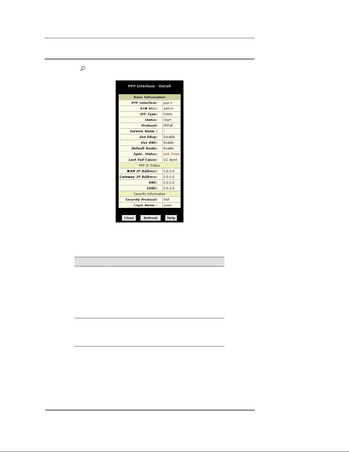
Best Data DSL542 ADSL Ethernet Router User’s Guide
Viewing PPP Interface Details
When you click to view additional details, the PPP Interface - Detail page displays, as shown
in Figure 38
Figure 37. PPP – Detail Pa ge
In addition to the properties defined on page 49, he Detail page displays these fields:
Field Description
Status
Service Name
Indicates whether the interface has been specified in the
system as:
Enabled: A connection will be established for use
when the device is turned on or rebooted.
Disabled: The PPP interface cannot curren tly be
used.
Start On Data: The PPP connection will be
made only when data is sent to the in terface (e.g., whe n
a LAN user attempts to use the Internet).
The name of the ISP service you are using with this PPP
connection. ISPs may offer different ty pes of services (for
example, for online gaming or busine ss
communications), each requiring a different login and
other connection properties.
49
Page 58

Best Data DSL542 ADSL Ethernet Router User’s Guide
Field Description
Last Fail Cause
DNS
SDNS
Security
Protocol
Login Name
Indicates the action that ended the previous PPP
session:
No Valid PADO Recvd: The unit initiated a PPoE
handshake but did not receive a packet in reply from the
ISP.
No Valid PADS Recvd: After the initial handshake,
the unit did not receive a confirmation packet from the
ISP.
Stopped by User: The user stopped the connection
(for example, by changin g the C on figura tion Ma nag er
settings for the PPP interface.)
No Activity: The PPP communication timed out, in
accordance with the timeout period specified on the PPP
Configuration page.
Auth Failure: The ISP could not authorize the
connection based on the user name and/or password
provided.
PADT recvd: The ISP issued a special packet ty pe
to terminate the PPP connection.
VC down: The Virtual Circuit between the unit and
the ISP is down.
Internal failure: A system software failure occurred.
The IP address of the DNS ser ver (lo cated wi th y our
ISP) used on this PPP conn ecti on.
The IP address of the secondary DNS server (located
with your ISP) used on this PPP connec tion.
The type of PPP security your ISP uses: PAP (Password
Authentication Protocol) or CHAP (Challenge
Handshake Authentication Protocol).
The name you use to log in to your ISP each time this
PPP connection is established.
50
Page 59
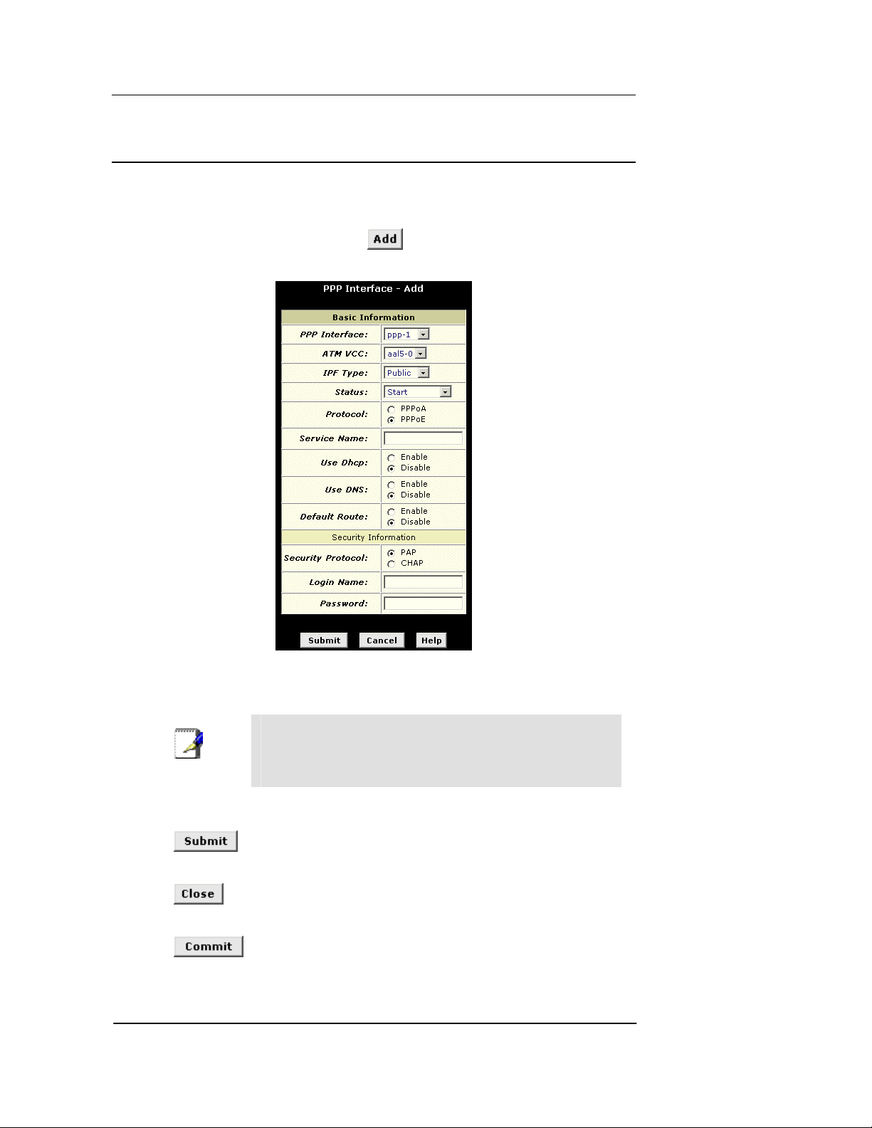
Best Data DSL542 ADSL Ethernet Router User’s Guide
Adding a PPP Interface Definition
If you intend to use more than one type of se rvice fr om y our ISP, the de vice may be co nfigured
with multiple PPP interfaces, each with unique logon and other properties. Follow this procedure
to define properties for a PPP interface:
1. From the PPP Configuration Page, click
.
The PPP Interface – Add page displays, as shown in Figure 39.
Figure 38. PPP Interface – Add Page
2. Select a PPP interface name from the drop-down list, and then enter or select data for
each field.
You can create multiple PPP interfaces only if you are using the
Note
PPoA protocol; only one PPP interface can be define if you are
using PPoE. Check with your ISP which version of the protocol
they require.
The fields are defined in the tables on page 49 and 50.
3. Click
.
A page displays to confirm your changes.
4. Click
5. Click the Admin tab, and then click
6. Click
to return to the PPP page and view the new interface in the table.
Commit & Reboot in the task bar.
to save your changes to permanent memory.
51
Page 60
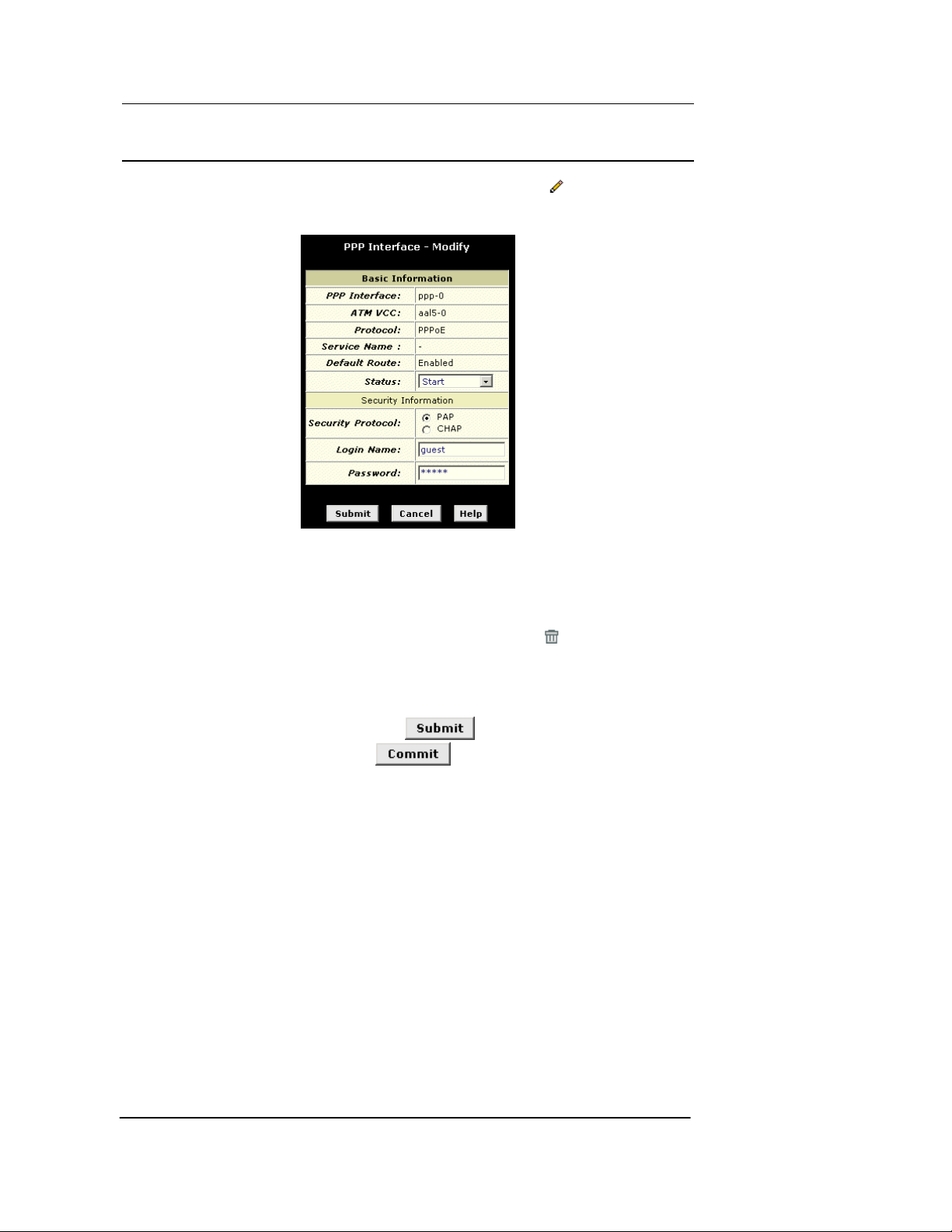
Best Data DSL542 ADSL Ethernet Router User’s Guide
Modifying and Deleting PPP Interfaces
To modify a PPP interface, display the PPP Configuration page and click in the Action(s)
column for the interface you want to modify. The PPP Interface – Modify page displays, as shown
in Figure 40.
You can change only the status of the PPP connection, the security protocol, your login name,
and your password. To modify the other se ttings, y ou must dele te the i nterface a nd create a n ew
one.
To delete a PPP interface, display the PPP Configuration page and click
column for the interface you want to delete . You sh ould no t delete a PP P inte rface unles s you
have received instructions to do so from your ISP. Without an appropriately defined PPP interface,
you will not be able to connect to y our ISP. You can recrea te the PPP interface w ith the s ame
name at a later time.
Figure 39. PPP Interface – Modify
in the Action(s)
After modifying or deleting a PPP interface , click
Commit & Reboot in the task bar, and click to save your changes to permanent
. Then, Click the Admin tab, click
memory.
52
Page 61
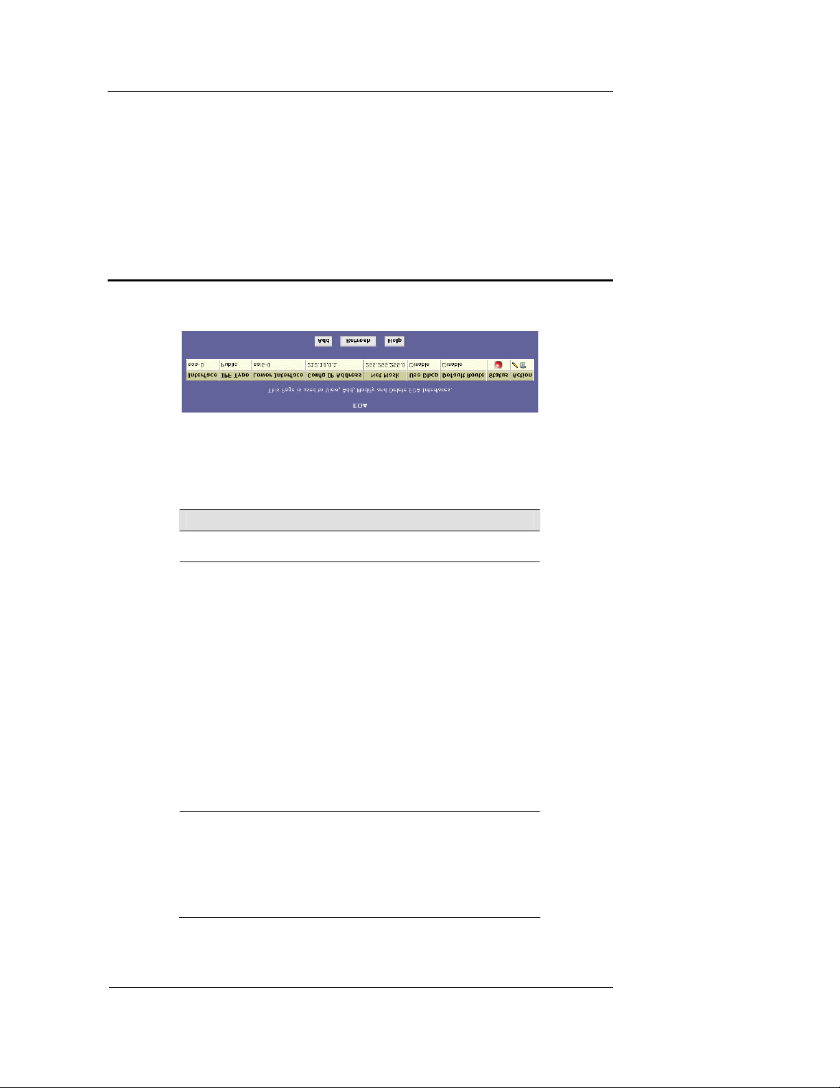
Best Data DSL542 ADSL Ethernet Router User’s Guide
11 Configuring EOA Interfaces
This chapter describes how to configure an Ethernet-over-ATM interface on the Best Data
DSL542, if one is needed to communicate with your ISP.
Viewing Your EOA Setup
To view your current EOA configuration , log into Con figura tion Mana ger, click Advanced in the
task bar, and then click
The EOA table contains a row for each EOA interface currently defined on the device. The table
may contain no entries if your ISP does not use the EOA protocol.
The following table describes the fields on this page:
EOA. Figure 41 shows the EOA configuration page.
Figure 40. EOA Page
Field Description
Interface
IPF Type
Lower interface
The name the software uses to identify the EOA
interface.
The type of IP Firewall protections in effect on the
interface (public, private, or DMZ):
A public interface connects to the Internet (IPoA
interfaces are typically public). Packets received on a
public interface are subject to the most restrictive set
of firewall p r o te c ti o ns d e fi n e d in the softwa r e.
A private interface connects to y our L AN, such
as the Ethernet interface. Packets received on a
private interface are subject to a less restrictive set of
protections, because they originate within the
network.
The term DMZ (de-militarized zone), in Internet
networking terms, refers to computers that are
available for both public and in-netwo rk accesses
(such as a company's public Web server). Packets
incoming on a DMZ interface—whether from a LAN
or external source—are subject to a level of pro tectio n
that is in between those for public and pri vate
interfaces.
EOA interfaces are defined in software, and then
associated with lower-level software and hardware
structures (at th e lo west level , t hey are asso ciate d
with a physical port —the WAN port). This field should
reflect an interface name defined in the next lower
level of software over which the EOA interface will
operate. This will be an ATM VCC i nterface, su ch as
aal5-0.
53
Page 62
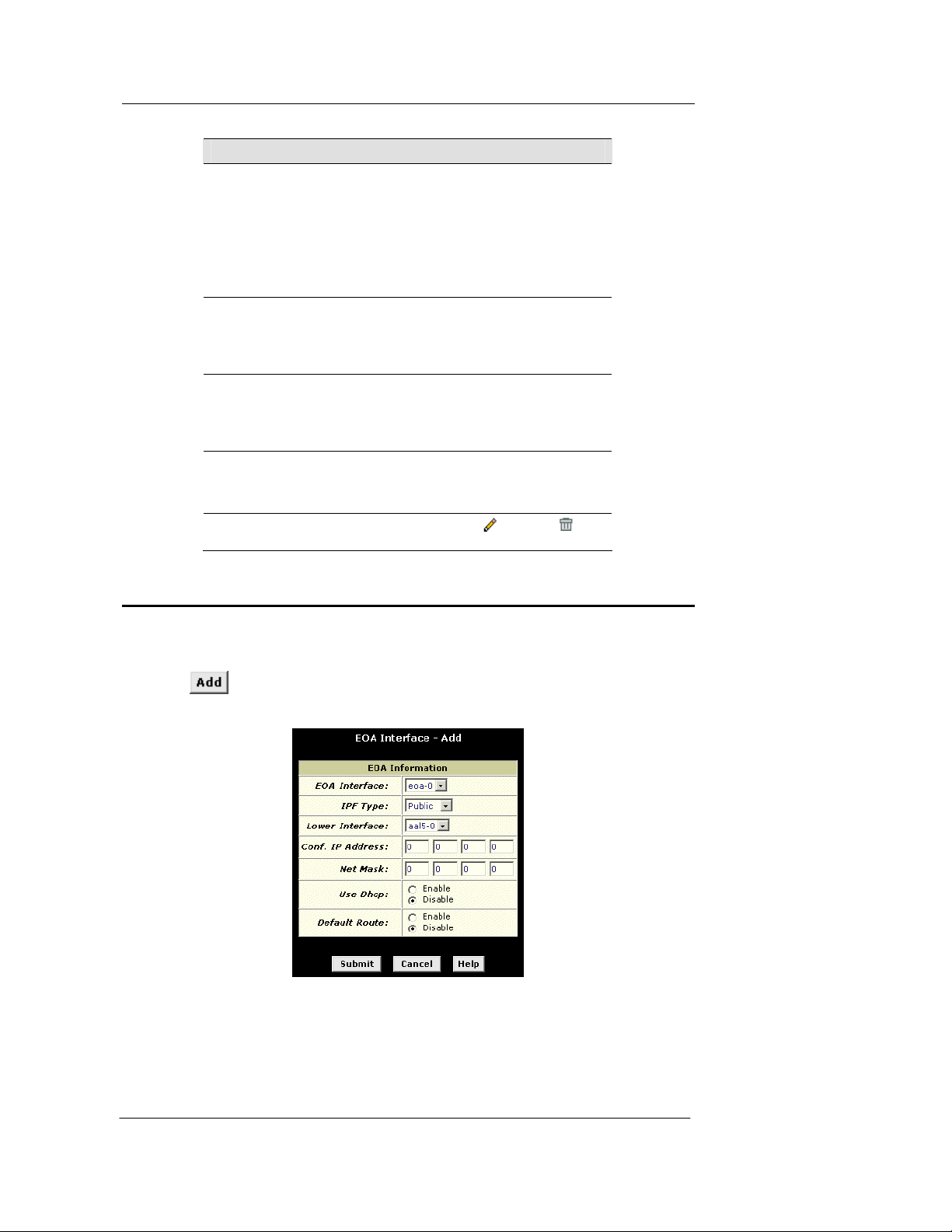
Best Data DSL542 ADSL Ethernet Router User’s Guide
Field Description
Config IP Addre ss
and
Net Mask
Use DHCP
Default Route
Status
Action
The IP address and network mask you want to assign
to the interface. If the interface will be used for
bridging with your ISP and you wi ll not be using the
Best Data DSL542 as a rou te r on y our LA N, th en y o u
do not need to specify IP inform ation. If y ou enable
DHCP for this interface, then the Configured IP
address will serve only as a request to the DHCP
server. The actual address that is assigne d by the
ISP may differ if this address is not available.
When checked, this setting instructs the device to
accept IP information assigned dy namica lly by your
ISP’s DHCP server. If the interface will be used for
bridging with your ISP and you wi ll not be routin g data
through it, leave this checkbox unselected.
Indicates whether the Best Data DSL542 should use
the IP address assigned to this interface, if any , as its
default route for your LAN. This can be Enable or
Disable. See Chapter 8 for an explanation of default
routes.
A green or red ball will display to indicate that the
interface is currently up or down, respectively. Yo u
cannot manually enable or disable the inte rface; a red
ball may indicate a problem with the DSL connection.
Icons you can click on to edit (
associated EOA interface.
) or delete ( ) the
Adding EOA Interfaces
Follow these instructions to add an EOA interface:
1. Click the WAN tab, and then click
2. Click
.
The EOA Interface – Add page displays, as shown in Figure 42.
Figure 41. EOA Interface – Add Page
3. Select one of the predefined interface names from the EOA Interface drop down list.
4. From the IPF Type drop-down list, select the level of IP Firewall to be used on this
interface, as defined above.
EOA in the task bar.
54
Page 63

Best Data DSL542 ADSL Ethernet Router User’s Guide
5. In the Lower Interface field, select the lower-level interface name over which this
protocol is being configured. Typically, an EOA interface is confi gured to operate over
an aal5 interface, such as aal5-0.
If you are using the Best Data DSL542 a s a bridge only, skip to step 7.
6. If you are using the Best Data DSL542 as a router on your LAN, enter the IP address
and network mask you want to assign to the interface. This address serves as the public
IP address for your entire LAN and is usually assigned by your ISP.
Or, if your ISP will assign this information, click the Enable radio button to set up the DHCP
service.
Also, specify whether this interface sh ould ser ve as the default route for y our LAN f or
accessing the Internet.
7. Click
.
A confirmation page display to confirm y our changes.
8. Click
9. Click the Admin tab, and the n click
10. Click
to return to the EOA page and view the new interface in the table.
Commit & Reboot in the task bar.
to save your changes to permanent memory.
55
Page 64
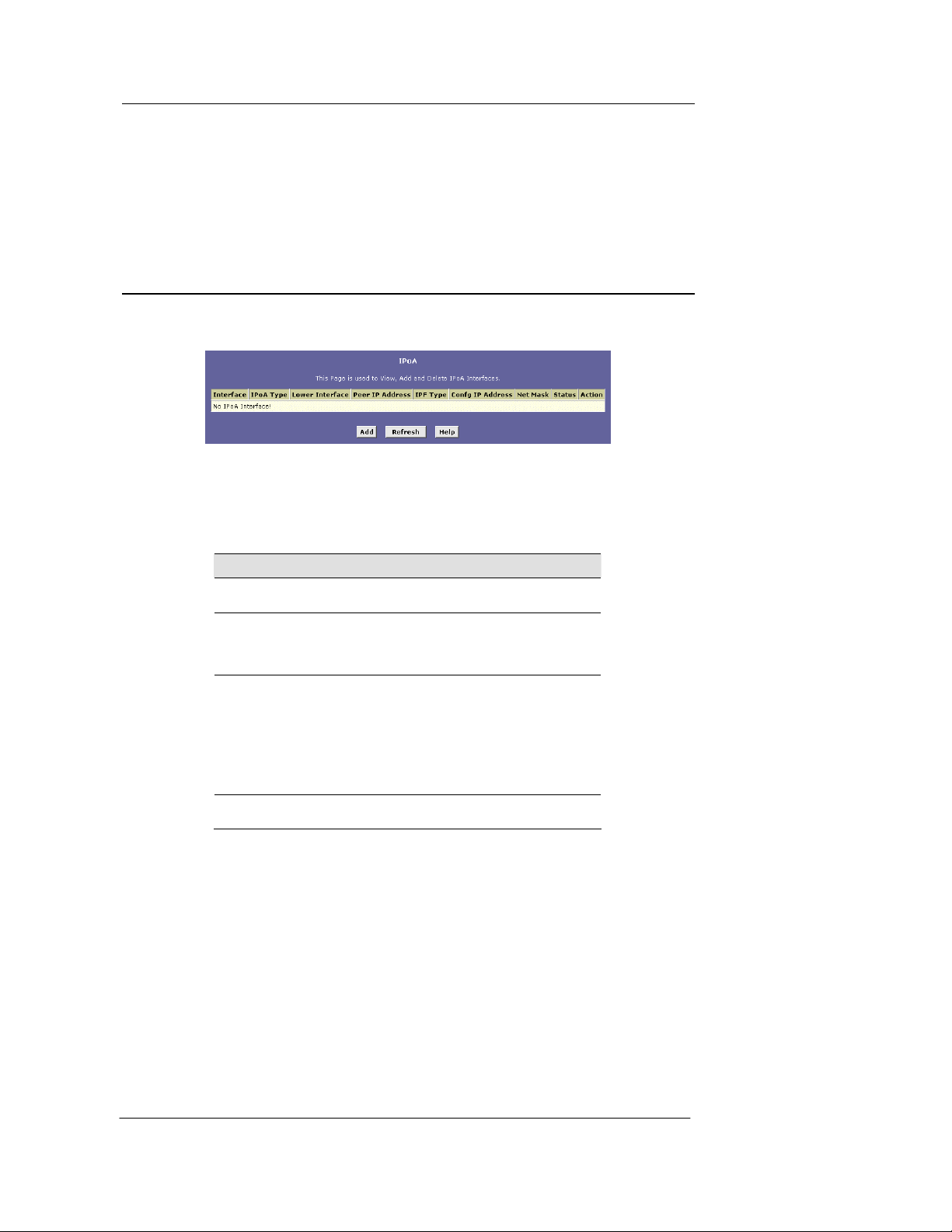
Best Data DSL542 ADSL Ethernet Router User’s Guide
12 Configuring IPoA Interfaces
This chapter describes how to configure an IPoA (Inter net Protoco l-over-ATM ) interface on the
Best Data DSL542.
Viewing Your IPoA Interface Setup
To configure an IPoA interface, log into Configuration Manager, click the WAN tab, and then click
IPoA in the task bar. The IPoA page disp lays, as sh own in F igure 43.
The IPoA table contains a row for each EOA interface currently defined on the device. The table
may initially contain no entries.
The following table describes the fields on this page:
Figure 42. IPoA Page
Field Description
Interface
IPoA Type
Lower interface
Peer IP Address
The name the software uses to identify the IPoA
interface
Specifies whether or not the IPoA protocol to be
used complies with the IEFT RFC 1577 "Classical
IP and ARP over ATM" (contact your ISP if
unsure).
IPoA interfaces are defined in software, an d the n
associated with lower-level software and hardware
structures (at the lowest level, th ey are associated
with a physical port – the WAN port). This field
should reflect an interface name defin ed in th e
next lower level of software over which the IPoA
interface will operate. This will be an ATM VCC
interface, such as aal5-0.
The IP address of the remote computer you w ill be
connecting to via the WAN interface.
56
Page 65
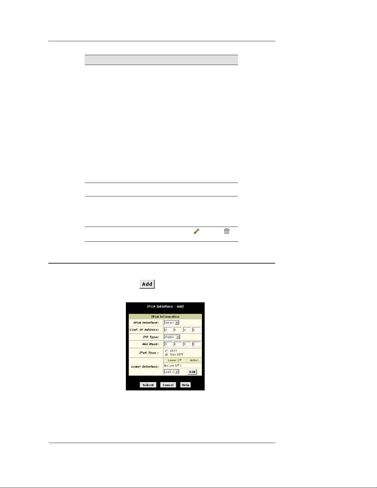
Field Description
IPF Type
Config IP Address
and Net Mask
Status
Action
The type of IP Firewall protections that are in
effect on the interface (public, private, or DMZ):
A public interface connects to the Internet
(IPoA interfaces are typically public). Packets
received on a public interface are subject to the
most restrictive set of firewall protections define d
in the software.
A private interface connects to your LAN,
such as the Ethernet interface. Packets received
on a private interface are subject to a less
restrictive set of protections, because they
originate within the network .
The term DMZ (de-militarized zone), in
Internet networking terms, refers to computers that
are available for both public and in -netwo rk
accesses (such as a company's public Web
server). Packets incoming on a DMZ in terface —
whether from a LAN or external source—are
subject to a level of p rotec tion that is in betw een
those for public and private interfaces.
The IP address and network mask you want to
assign to the interface.
A green or red ball will display to indicate that t he
interface is currently up or down, respectively. You
cannot manually enable or di sable the inte rface; a
down interface may ind icate a pro blem wi th th e
DSL connection.
Icons you can click on to edit (
the associated EOA interface.
Best Data DSL542 ADSL Ethernet Router User’s Guide
) or delete ( )
Adding IPoA Interfaces
Follow these instructions to add an IPoA interface :
1. Display the IPoA page and click
The IPoA Interface – Add page displays, as shown in Figure 44.
Figure 43. IPoA Interface – A dd Page
2. Select the next available interface name from the IPoA Interface drop-down list.
3. In the Configured IP Address and Net Mask boxes, type the address and mask that you
want to assign to the IPoA interface.
.
57
Page 66

Best Data DSL542 ADSL Ethernet Router User’s Guide
4. Select the level of firewall security to apply to the interface by selecting the IPF Type as
Public, Private, or DMZ.
5. In the Lower Interface dialog box, select the lower-level interface name over which this
protocol is being configured and click . Typically, an IPoA interface is configured
to operate over an aal5 interface.
6. Click
.
A confirmation page will display to confirm your changes.
7. Click
to return to the EOA page and view the new interface in the table.
8. Click the Admin tab, and then click
9. Click
to save your changes to permanent memory.
Commit & Reboot in the task bar.
58
Page 67
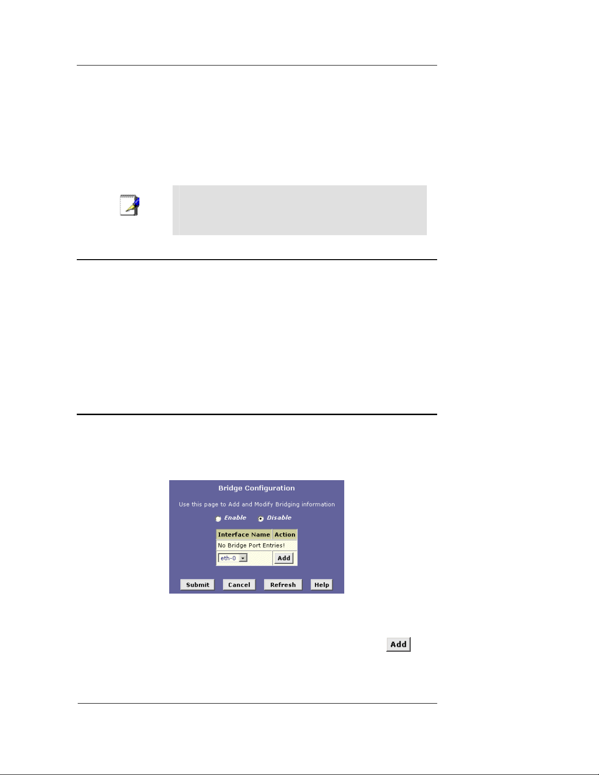
Best Data DSL542 ADSL Ethernet Router User’s Guide
13 Configuring Bridging
The Best Data DSL542 can be configured to act as a br idging de vice betwe en your LAN and y our
ISP. Bridges are devices that enable two or more networks to communicate as if they are two
segments of the same physical LAN. This chapter describes how to configure the Best Data
DSL542 to operate as a bridge.
Before changing your bridge configuration, check with your ISP to
Note
Using the Bridging Feature
Although the Best Data DSL542 is preconfigured to serve as a router for providing Internet
connectivity to you LAN, there are se veral in stance s in whic h you may also want to config ure
bridging:
f Your ISP may use protocols that require bridging with your LAN. The device can be
configured to appear as a bridge when communicating with your ISP, while continuing to
provide router functionality for your LAN.
f Your LAN may include computers that co mmunicat e usin g “layer-3” p rotoc ols other than
the Internet Protocol. These include IPX
configured to act as a bridge for packets that use these protocols while continuing to
serve as a router for IP data.
In both cases, you need to specify the de vice’s interfaces a s bridge inte rfaces.
determine the type of connection they use t o exchan ge data with
their customer’s DSL modems (such as E thernet bri dging or IP
routing).
®
and AppleTalk®.. In this case, the device can be
Defining Bridge Interfaces
To enable bridging, you simply specify the device interfaces on which you want to bridge data,
and then enable bridging mode:
1. Log into Configuration Manager and click the Bridging tab.
The Bridge Configuration page displays, as shown in Figure 45.
The table may be empty if bridging has not yet been configured.
2. Select the interface names on which you want to perform bridging and click
For example, select eth-0 (LAN) and eoa-0 (WAN) interfaces. If you use such protocols on a
USB-connected computer, you can also select usb-0.
Figure 44. Bridge Configuration page
.
59
Page 68

Best Data DSL542 ADSL Ethernet Router User’s Guide
You have to create an entry for usb-0 inferface via RS-232 cable.
Please refer the procedure on page 10 and type “create bridge
port intf ifname usb-0” on step 7.
If you do not have an eoa-0 interface, but instead have an
Note
interface named ppp-0 or ipoa-0, your device is not cu rrently
configured with a WAN interface that allo ws bridgi ng with y our
ISP. You may want to check with your ISP to determin e whether
they use the eoa protocol. See Chapter 11 for instructions on
creating an EOA interface.
If you enable bridging on an interface that has already been
assigned an IP address, then it is con sidered IP-enab led and will
route (rather than bridge) IP packets received on the interface.
The interface will bridge non-IP data it receives, however.
You can determine whether the Ethernet (eth-0) and USB (usb-0)
interfaces have been assigned IP addresses by displaying the IP
Note
Address Table (display the Routing tab, and then click IP
Address). These interfaces will display in the table only if they
have been assigned IP addresses.
You can check whether the eoa-0 interface has been assigned an
IP address by displaying the EOA configuration table (click the
WAN tab, and then click EOA). If the Config IP Address field is
empty and the Use DHCP field contains the word Disable, then no
IP address has been assigned.
3. Click the Enable radio button to turn on b ridging.
4. Click
.
A page will briefly display to confirm your c hanges, a nd will re turn you to the Bridge
Configuration page.
5. Click the Admin tab, and the n click
6. Click
to save your changes to permanent memory.
Commit & Reboot in the task bar.
Deleting a Bridge Interface
1. To make an interface non-bridgeable, display the Bridge Configuration page and click
next to the interface you want to delete. Click
interface remains defined in the system, but is no longer capable of perf orming bridging.
to confirm the deletion. The
60
Page 69

Best Data DSL542 ADSL Ethernet Router User’s Guide Index
A Troubleshooting
This appendix suggests solutions for problems you may encount er in installing or using the Best
Data DSL542, and provides instructions for using several IP utilities to diagnose problems.
Contact Customer Support if these suggestions do not resolve the problem.
Problem Troubleshooting Suggestion
LEDs
Power LED does not
illuminate after product is
turned on.
LINK WAN LED does
not illuminate after
phone cable is attached.
LINK LAN LED does not
illuminate after Ethernet
cable is attached.
Internet Access
PC cannot access Internet
PCs cannot display web
pages on the Internet.
Verify that you are using the power cable provided
with the device and that it is securely connected to
the Best Data DSL542 and a wall socket/power strip.
Verify that a standard telephone cable like the one
provided is securely connected to the ADSL port and
your wall phone jack. Wait 30 seconds to allow the
device to negotiate a connection with your ISP.
Verify that the Ethernet cable is securely connected
to your LAN hub or PC and to the Best Data
DSL542. Make sure the PC and/or hub is turned on.
Verify that you are using a straight-through type
Ethernet cable to the uplink port on a hub or a crossover type cable to a stand-alone PC. If you
connected the device to an ordinary hub port (not
Uplink), you must use a straight-through cable. (Hold
the connectors at each end of the cable side-by-side
in the same position. If the order of their color-coded
wire pairs is the same, it is a straight-through type.)
Contact Customer Support if your cable is not the
correct type.
Verify that your cable is sufficient for your network
requirements. A 100 Mbit/sec network (10BaseTx)
should use cables labeled Cat 5. 10Mbit/sec cables
may tolerate lower quality cables.
Use the ping utility, discussed in the following
section, to check whether your PC can communicate
with the Best Data DSL542’s LAN IP address (by
default 192.168.1.1). If it cannot, check the Ethernet
cabling.
If you statically assigned a private IP address to the
computer, (not a registered public address), verify
the following:
Check that the gateway IP address on the
computer is your public IP address. If it is not, correct
the address or configure the PC to receive IP
information automatically.
Verify with your ISP that the DNS server
specified for the PC is valid. Correct the address or
configure the PC to receive this information
automatically.
Verify that a Network Address Translation
rule has been defined on the Best Data DSL542 to
translate the private address to your public IP
address. The assigned IP address must be within the
range specified in the NAT rules (see Chapter 7). Or,
configure the PC to accept an address assigned by
another device. The default configuration includes a
NAT rule for all dynamically assigned addresses
within a predefined pool (see the instructions in
Chapter 6 to view the address pool).
Verify that the DNS server specified on the PCs is
correct for your ISP, as discussed in the item above.
You can use the ping utility, discussed in the following
section, to test connectivity with your ISP’s DNS server.
61
Page 70

Index Best Data DSL542 ADSL Ethernet Router User’s Guide
Problem Troubleshooting Suggestion
Configuration Manager Program
You forgot/lost your
Configuration Manager
user ID or password.
Cannot access the
Configuration Manager
program from your
browser.
Changes to
Configuration Manager
are not being retained.
If you have not changed the password from the
default, try using “root” as both the user ID and
password. Otherwise, you can reset the device to the
default configuration by pressing the Reset button on
the back panel of the device (using a pointed object
such as a pen tip). Then, type the default User ID
and password shown above. WARNING: Resetting
the device removes any custom settings and returns
all settings to their default values.
Use the ping utility, discussed in the following
section, to check whether your PC can communicate
with the Best Data DSL542’s LAN IP address (by
default 192.168.1.1). If it cannot, check the Ethernet
cabling.
Verify that you are using Internet Explorer v5.0 or later,
or Netscape Navigator v4.7 or later. Support for
Javascript® mus t be en ab le d i n y o ur b r owser. Support
for Java® may also be required.
Verify that the PC’s IP address is defined as being on
the same subnet as the IP address assigned to the LAN
port on the Best Data DSL542.
Be sure to use the Commit function after any changes.
This function is described on page 17.
62
Page 71
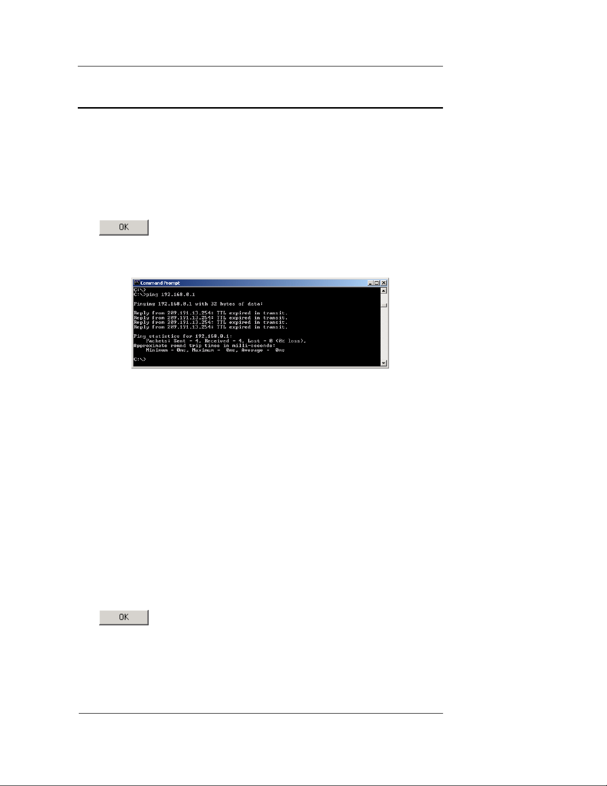
Best Data DSL542 ADSL Ethernet Router User’s Guide Index
Diagnosing Problem using IP Utilities
ping
Ping is a command you can use to check whether your PC can recognize other computers on
your network and the Internet. A ping command sends a message to the computer you specify. If
the computer receives the message, it s ends message s in reply . To use it , you must know the IP
address of the computer you are trying to communicate w ith.
On Windows-based computers, you can execute a ping command from the Start menu. Click the
Start button, and then click Run. In the Open text box, ty pe a statement su ch as the following :
ping 192.168.1.1
Click
. You can substitute any private IP address on your LAN or a public IP address
for an Internet site, if known.
If the target computer receives the message, a Command Prompt window displays like that shown
in Figure .
Figure 45. Using the ping Utility
If the target computer cannot be loca ted, you w ill receive the me ssage “Reque st time d out.”
Using the ping command, you can test whether the path to the Best Data DSL542 is working
(using the preconfigured default LAN IP address 192.168.1.1) or another address you assigned.
You can also test whether access to th e Internet is workin g by ty ping an ex ternal addre ss, su ch as
that for www.yahoo.com (216.115.108.243). If you do not know the IP address of a particular
Internet location, you can use the nslookup command, as explained in the following section.
From most other IP-enabled operating systems, you can execute the same command at a
command prompt or through a sy stem ad ministrat ion utility .
nslookup
You can use the nslookup command to de termine the IP addres s associa ted with an internet sit e
name. You specify the common name, and the nslo okup comman d looks up the n ame in on y our
DNS server (usually located with your ISP). If that name is not an en try in your ISP ’s DNS table,
the request is then referred to another higher-level server, and so on, until the entry is found. The
server then returns the associated IP address.
On Windows-based computers, you can execute the nslookup command from the Start menu.
Click the Start button, and then click R un. In the Open text box, ty pe the follow ing:
nslookup
Click
. A Command Prompt window displays with a bracket pr ompt (>). At th e
prompt, type the name of the internet address your are interested in, such as www.microsoft.com.
The window will display the associate IP addre ss, if kno wn, as sh own in F igure 1.
63
Page 72

Index Best Data DSL542 ADSL Ethernet Router User’s Guide
Figure 1. Using the nslookup Utility
There may be several addresses associated with an Internet name. This is common for web sites
that receive heavy traffic; they use multipl e, redunda nt serve rs to ca rry the same in formatio n.
To exit from the nslookup utility, ty pe exit and press <Enter> at the command prompt.
64
 Loading...