

Page 1

TABLE OF CONTENTS
Introduction ..................................................................2
Software and hardware features ..................................2
System components ....................................................3
HBV specifications........................................................4
HBV functions ..............................................................5
HBV lever styles ............................................................5
KBV specifications ........................................................6
KBV functions ..............................................................7
INTRODUCTION
Introducing B.A.S.I.S.™V – a highly efficient stand-alone lock system that utilizes card reader technology and is integrated
TABLE OF CONTENTS
FEATURES
into B.A.S.I S.™ 2000. With B.A.S.I.S.™V, ID cards are encoded with all the necessary information to control door access.
The system integrates with virtually any existing database, and allows unsurpassed capabilities in storing and retrieving
access activity data. B.A.S.I.S.™V involves no costly wiring, is easy to manage, and offers a broad range of integrated
features. In fact, everything about B.A.S.I.S.™V was designed to think ... so you don’t have to.
SOFTWARE FEATURES
• B.A.S.I.S.™V (an off-line system) is integrated into BEST’s on-line software, eliminating the inefficiencies of having two
separate systems – one for off-line and one for on-line.
• Dynamically integrates with most existing databases with real-time information updates, eliminating the tedious process
of re-entering user data.
• Multiple locations can be networked to conveniently access a single database.
• Complete history of access activity can easily be obtained.
• Automatic backup reduces the risk of losing data.
• Operates on a desktop PC, or laptop PC with minimal system requirements.
• Provides easy-to-use menus and dialog boxes.
• Is password protected.
• Lets you create lockset configurations, which include programming settings and a user card database, from a remote PC.
• Stores as many lockset configurations as you have disk space for.
• Programs and retrieves data from locks.
• Lets you create new lockset configurations by copying
and editing existing configurations.
• Lets many locks share the same lockset configuration.
• Can transfer data between PCs.
• Downloading and printing of history events.
• Creating standardized lock configuration templates.
PagePage
KBV lever styles....................................................................7
Options ................................................................................7
Software overview ................................................................8
System architecture..............................................................9
Standard cards....................................................................10
Order procedure ..........................................................10, 11
Battery life chart ................................................................11
HARDWARE FEATURES
• Mag stripe available as track 1 or track 2.
• Swipe reader that reads ISO standard size I.D. cards.
• Battery life varies depending on the token reader and chassis type chosen. (See page 11 for battery pack chart.)
• Costs are controlled by availability of replacement parts versus having to replace entire unit.
• Local factory-trained technical services are available 24 hours a day to meet any emergency need.
• B.A.S.I.S.™V can allow or record 5,000 users /history per lockset.
• Heavy-duty mechanical platform designed and manufactured for the toughest applications.
• Key override detection records and documents when a key is used. (Key override feature standard on B.A.S.I.S.™V.)
• Deadbolt sensing prevents access to unauthorized cards when deadbolt is thrown.
• Interchangeable core mechanical override allows for emergency access.
• B.A.S.I.S.™V hardware is available in trims and most finishes that match BEST’s 9K cylindrical series and 30H mortise
series, providing aesthetic continuity.
• Weather-resistant for versatile applications, including doors exposed to inclement conditions.
• Available in Motorola and HID proximity readers, smart card, mag stripe card, and combination mag stripe dual keypad.
STAND-ALONE EL
2
STAND-ALONE EL
Page 2
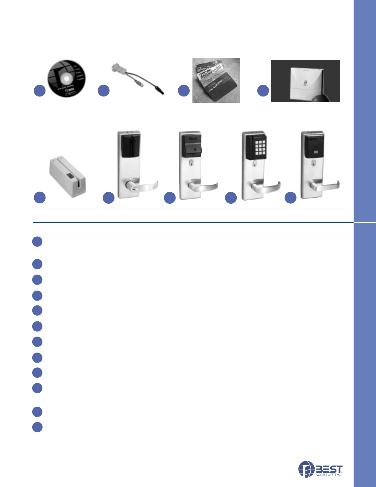
SYSTEM COMPONENTS
The B.A.S.I.S.™V System is an electronic access control system that can be programmed to meet your facilities access
control needs. The system is designed to secure your facility by granting specific access rights to authorized people, based
on a defined time schedule for each lock in the system. By tracking events at the locks, the system provides information to
help you maintain the security of your facility.
1
B.A.S.I.S.
Software
2
3
Programming
Cable
Mag Stripe Cards/
4
Smart Card Encoder
Proximity Cards/
Smart Card Cards
5
Mag Stripe
Encoder
1
B.A.S.I.S. Software– Software that lets you define programming settings and the user database for groups of locks, as
6
Mag Stripe
Electronic Lock
7
Smart Card
8
Dual Validation
Electronic Lock
SYSTEM COMPONENTS DESCRIPTION
Reader
9
Proximity
Reader
well as individual locks. The software lets you view and print information about locks at any time.
(To order, contact your local Best Access Systems office.)
2
Programming Cable – Programming cable allows you to connect to individual locks.
(To order, contact your local Best Access Systems office.)
3
Smart Card Cards – A credit-card-size card with a smart card chip containing information. These cards can be encoded
and sent to the user or encoded by the user at their facility. (To order, see page 10.)
3
Mag Stripe Cards – A credit-card-size card with a magnetic stripe containing information. These cards can be
encoded and sent to the user or encoded by the user at their facility. (To order, see page 10.)
3
Proximity Cards – A credit-card-size card with a proximity chip containing information. These cards can be
encoded and sent to the user or encoded by the user at their facility. (To order, see page 10.)
4
Smart Card Encoder – The device that “reads”, “writes” and “erases” information on the smart card. This also
includes the software that controls the card encoder. Requires a PC B.A.S.I.S. software. (To order, see page 11.)
5
Mag Stripe Card Encoder – The device that “reads”, “writes” and “erases” information on the magnetic-stripe card.
This also includes the software that controls the card encoder. Requires a PC & B.A.S.I.S. software. (To order, see page 11.)
6
Mag Stripe Electronic Lock – A battery-powered, self-contained swipe reader electronic lock that uses standard
mag stripe cards. Controls access to door and can be programmed with B.A.S.I.S. software. (To order, see page 10.)
7
Smart Card Electronic Lock – A battery-powered, self-contained insertion reader electronic lock that uses smart cards.
Controls access to door and can be programmed with B.A.S.I.S. software. (To order, see page 10.)
8
Dual Validation Reader – A battery-powered, self-contained dual validation reader electronic lock that combines standard
mag stripe and keypad validation. Controls access to door and can be programmed with B.A.S.I.S. software.
(To order, see page 10.)
9
Proximity Reader – A battery-powered, self-contained proximity card reader electronic lock that uses standard proximity
cards. Controls access to door and can be programmed with B.A.S.I.S. software.
10
PDA (palm top not shown) – A PDA (Personal Digital Assistant) is a palm top device that connects to a PC to transport
(To order, see page 10.)
programming data from a B.A.S.I.S. system to the lockset or retrieve history data. The PDA can also provide diagnostic
data from the lockset. Software for the palm device is included in the B.A.S.I.S. software.
(Contact your local Best Access Systems office or visit our web site for a recommended BEST–supported device.)
SYSTEM COMPONENTS
COMPONENTS DESCRIPTION
ECTRONIC LOCKS
ECTRONIC LOCKS
3
Page 3
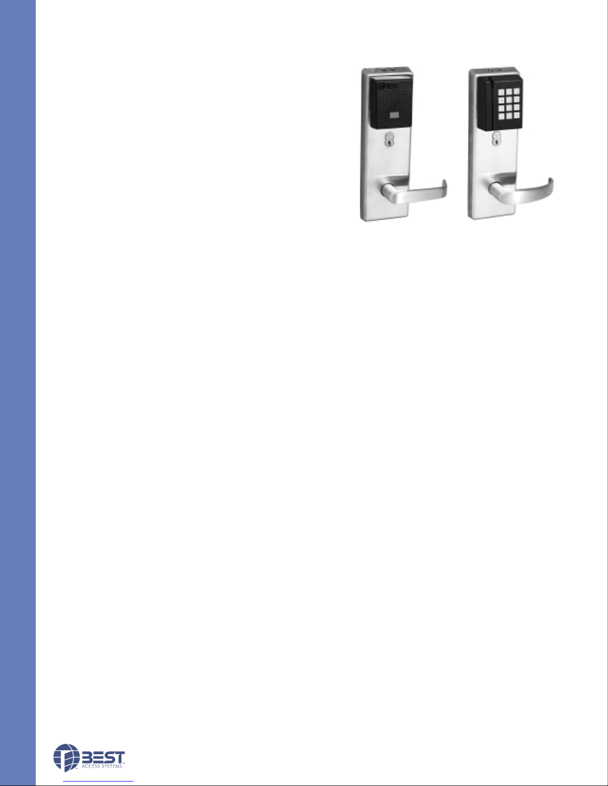
HBV SPECIFICATIONS
MECHANICAL
Case: Heavy wrought steel, 5 7⁄8" H x 41⁄4" D x 1" W steel parts are
zinc dichromate plated for corrosion protection.
Faceplate: Brass or bronze, 11⁄4" x 8" x 7⁄32" . Armored. Adjustable
from flat to beveled 1⁄8" – 2" .
Strike: Brass or bronze, 4 7⁄8" x 11⁄4" x 3⁄32". Fits standard door frame
cut out as specified in ANSI A115.1. Correct strike automatically
supplied with unit. Strike box supplied standard.
Door thickness: For doors 13⁄4" - 3" thick.
Installation: Lock requires modified door prep to mount the trim.
Faceplate dimensions fit standard door preparation as specified in
ANSI A115.1. Lockset is reversible for hand of door.
Latchbolt: Stainless steel, 3⁄4" throw with anti-friction latch.
HBV SPECIFICATIONS
Deadbolt: Solid stainless steel, 1" throw.
Auxiliary bolt: Stainless steel.
Die cast trim housing: Dimensions: 10 3⁄8" H x 3 1⁄4" W x 1" D
sloping down to 3⁄4".
Lever handle: Brass, bronze or stainless steel. (Lever #3, #14 and #15 conform to California Titles 19 and 24.)
Mounting: Lever attached with hardened set screw on inside knob or inside lever.
Finish: 605-bright brass, clear coated; 606-satin brass, clear coated; 611-bright bronze, clear coated; 612-satin bronze,
clear coated; 613-oxidized satin bronze, oil rubbed; 625-bright chromium plated; 626-satin chromium plated; 629-bright
stainless steel; 630-satin stainless steel.
ELECTRONIC
SPECIFICATIONS FOR ALL READERS:
Primary power: Alkaline standard 4 cell or extended life cell battery pack.
Memory backup: Maintains programming and history data for up to 3 months after loss of power.
User feedback indicators: Visual and audible.
Serial communications port: Can be used to program locks individually.
Operating temperature: -35°C to +66°C (-31°F to +151°F).
Relative humidity: 10% to 90% non-condensing.
Sealing: Weatherproof lens and gasket provides protection for outdoor use.
(Usable in all environmental/exterior applications.)
Battery Life: See page 11 for battery life chart.
Proximity Reader
Dual Validation Reader
Dual Validation – Combination Keypad & Magstripe Reader:
Bezel size: 2 5⁄8" x 3 1⁄4" .
Material: Bezel– High impact ABS. Keypad– Encapsulated elastomer.
ESD Protection: 15KV.
Button operating life: 1 million cycles.
Operating temperature: -35°C to +66°C (-31°F to +151°F).
Compliant to FCC and Canadian EMC requirements; ISO 7816, MP-COS EMV compliant; T0 & T1 protocol standard.
Magnetic Stripe Card Reader:
Read Rate: 5 inches per second to 50 inches per second.
Card thickness: ISO standard .030"±.003 thick.
Compliance to FCC, Canadian, and European EMC requirements; for interference FCC Class A digital apparatus.
Proximity Reader:
Bezel size: 2 5⁄8" x 3 1⁄4"
Material: Bezel–High impact ABS.
ESD Protection: 15KV.
Reader range: Card reader range 0" – 3".
Compliance to FCC, Canadian, and European EMC requirements; for interference FCC Class A digital apparatus.
Smart Card Reader – Contacted Insertion Reader:
Operating temperature (exterior side of door): -35°C to +66°C (-31°F to +151°F).
Smart card adaptation: Trim option that can accept other manufacturers’ cylinder.
Compliant to FCC and Canadian EMC requirements; ISO 7816, MP-COS EMV compliant; T0 & T1 protocol standard.
STAND-ALONE EL
4
STAND-ALONE EL
Page 4
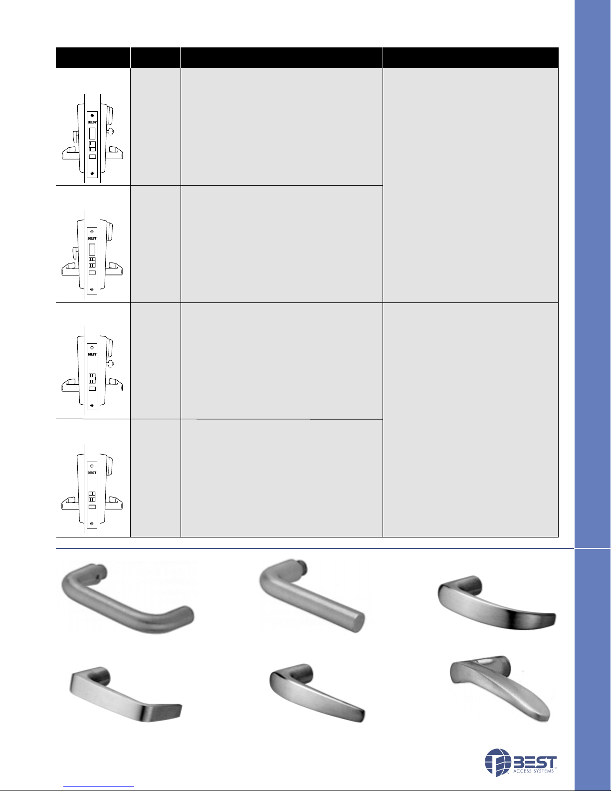
HBV FUNCTIONS
Diagram Function Mechanical Electronic
Deadbolt w/
key override
Deadbolt w/o
key override
Code
FV
LV
Latchbolt operated by lever either side,except
when outside lever is locked by internal motor
drive mechanism; latchbolt is retracted by key
outside. Deadbolt operated by key outside and
turn lever inside. When deadbolt is extended,
turning inside lever or electronically unlocked
outside lever retracts both deadbolt and
latchbolt simultaneously. Auxiliary latch
deadlocks latchbolt.
Latchbolt operated by lever either side, except
when outside lever is locked by internal motor
drive mechanism. Deadbolt operated by turn
knob inside. When deadbolt is extended,
turning inside lever or electronically unlocked
outside lever retracts both deadbolt and
latchbolt simultaneously. Auxiliary latch
deadlocks latchbolt.
Internal motor drive mechanism
operated by electronic signal when
presenting valid card. Green light
indicates valid access. Red light and
sounder indicate invalid access attempt.
Lock records card number, time, date
and type of event. Electronic sensor
recognizes whether deadbolt is
retracted or thrown. Lock grants access
only to deadbolt-authorized personnel
when deadbolt is thrown.
HBV FUNCTIONS
Latch w/key
override
Latch w/o
key override
EV
NV
Latchbolt operated by lever either side,except
when outside lever is locked by internal motor
drive mechanism; latchbolt is retracted by key
outside. Auxiliary latch deadlocks the latchbolt.
Latchbolt operated by lever either side, except
when outside lever is locked by internal motor
drivemechanism. Auxiliary latch deadlocks the
latchbolt.
Internal motor drive mechanism operated
by electronic signal, when presenting valid
card. Green light indicates valid access.
Red light and sounder indicate invalid
access attempt. Lock records card
number, time, date and type of event.
HBV LEVER STYLES
#3 lever #12 lever #14 lever
#15 lever #16 lever #17 lever
ECTRONIC LOCKS
ECTRONIC LOCKS
HBV LEVER STYLES
5
Page 5
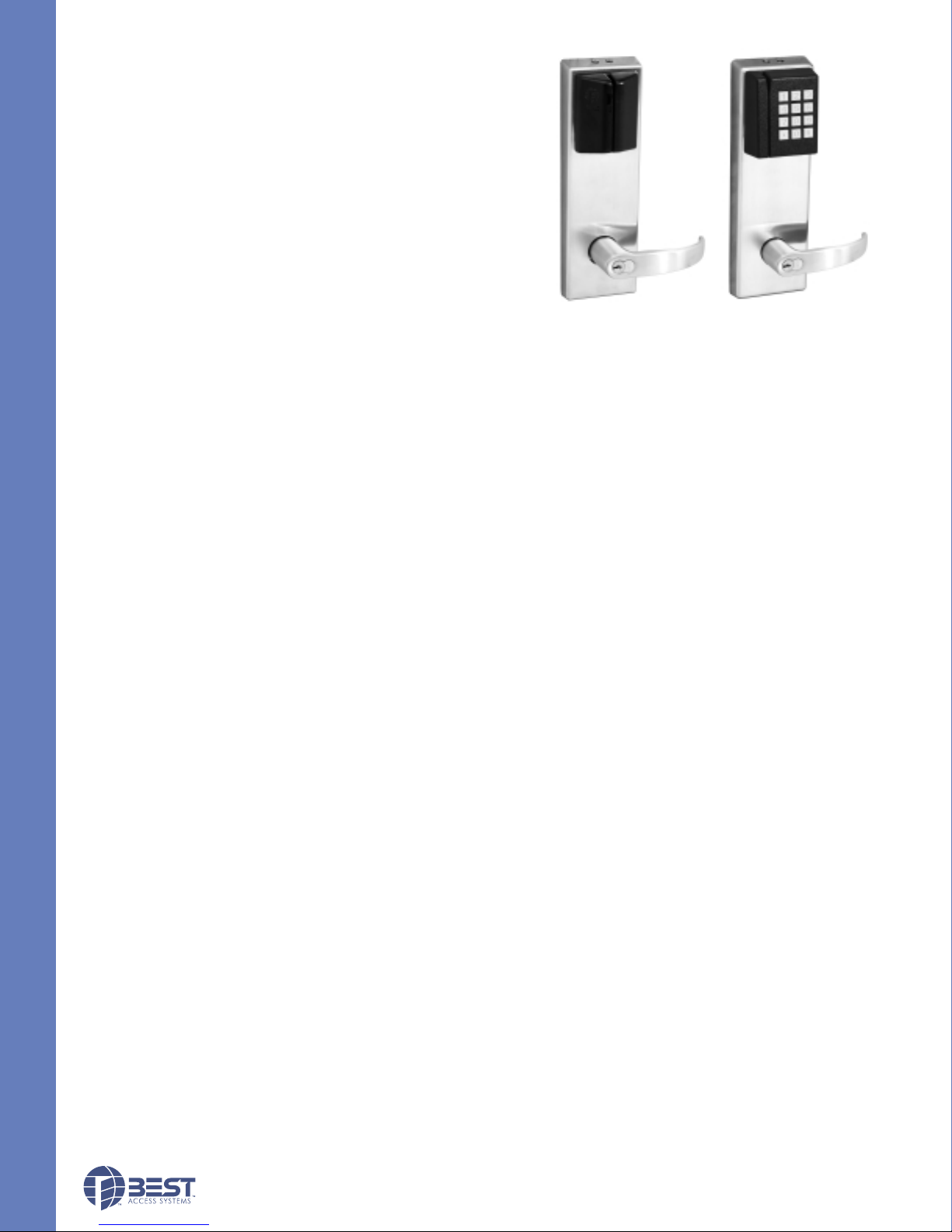
KBV SPECIFICATIONS
MECHANICAL
Materials: Internal parts are brass, zinc or corrosion-treated steel.
Chassis: 2 1⁄16" diameter to fit 2 1⁄8" diameter hole in door.
Strike: Brass or bronze, 4 7⁄8" x 11⁄4" x 3⁄32". Fits standard door
frame cut out as specified in ANSI A115.1. Correct strike
automatically supplied with unit. Strike box supplied standard.
Backset: 2 3⁄4" standard. 3 3⁄4" and 5" available.
Door thickness: For doors 13⁄4" - 2 1⁄4" thick.
Installation: Lock dimensions requires modified door prep,
ANSI A156.2 Series 4000, Grade 1 to mount housing.
Latchbolt:9⁄16" throw.
Die cast trim housing: Dimensions: 10 3⁄8" H x 3 1⁄4" W x 1" D sloping
down to 3⁄4".
KBV SPECIFICATIONS
Lever handle: Made from high-quality zinc alloy. Body is
approximately 15⁄8" in diameter. Handle is approximately 4 3⁄4" in length (from center-line of chassis).
(Lever #3, #14 and #15 conform to California Titles 19 and 24.)
Finish: 605-bright brass, clear coated; 606-satin brass, clear coated; 611-bright bronze, clear coated; 612-satin bronze,
clear coated; 613-oxidized satin bronze, oil rubbed; 625-bright chromium plated; 626-satin chromium plated.
ELECTRONIC
SPECIFICATIONS FOR ALL READERS:
Primary power: Alkaline standard 4 cell or extended life cell battery pack.
Memory backup: Maintains programming and history data for up to 3 months after loss of power.
User feedback indicators: Visual and audible.
Serial communications port: Can be used to program locks individually.
Operating temperature: -35°C to +66°C (-31°F to +151°F).
Relative humidity: 10% to 90% non-condensing.
Sealing: Weatherproof lens and gasket provides protection for outdoor use.
(Usable in all environmental/exterior applications.)
Battery Life: See page 11 for battery life chart.
Magnetic Stripe Reader
Dual Validation Reader
Dual Validation – Combination Keypad & Magstripe Reader:
Bezel size: 2 5⁄8" x 3 1⁄4" .
Material: Bezel– High impact ABS. Keypad– Encapsulated elastomer.
ESD Protection: 15KV.
Button operating life: 1 million cycles.
Compliant to FCC and Canadian EMC requirements; ISO 7816, MP-COS EMV compliant; T0 & T1 protocol standard.
Magnetic Stripe Card Reader:
Read Rate: 5 inches per second to 50 inches per second.
Card thickness: ISO standard .030"±.003 thick.
Compliance to FCC, Canadian, and European EMC requirements; for interference FCC Class A digital apparatus.
Proximity Reader:
Bezel size: 2 5⁄8" x 3 1⁄4"
Material: Bezel–High impact ABS.
ESD Protection: 15KV.
Reader range: Card reader range 0" – 3".
Compliance to FCC, Canadian, and European EMC requirements; for interference FCC Class A digital apparatus.
Smart Card Reader – Contacted Insertion Reader:
Operating temperature (Exterior side of door): -35°C to +66°C (-31°F to +151°F).
Smart card adaptation: Trim option that can accept other manufacturers’ cylinder.
Compliant to FCC and Canadian EMC requirements; ISO 7816, MP-COS EMV compliant; T0 & T1 protocol standard.
6
STAND-ALONE EL
Page 6
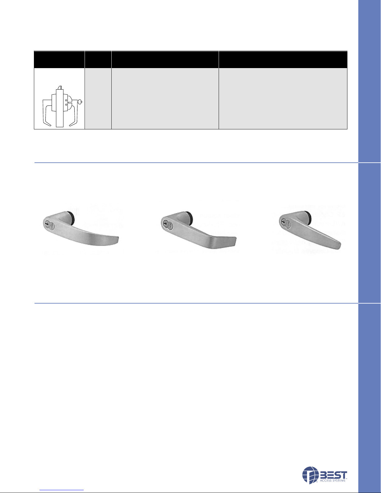
KBV FUNCTIONS
Diagram Function Mechanical Electronic
Code
Cylindrical Latch
w/key override
DV Dead locking latchbolt operated by lever Internal motor drive mechanism operated by
either side, except when outside lever is time-activated electronic signal, or presenting
locked by internal motor drive mechanism; valid card/PIN. Green light indicates valid
latchbolt is deadlocked. access. Red light and sounder indicate invalid
access attempt. Lock records card/PIN number,
time, date and type of event.
KBV LEVER STYLES
KBV FUNCTIONS
#14 lever #15 lever #16 lever
OPTIONS
AL– Abrasive levers from Best Access Systems are available with a special abrasive feature. Abrasive strip on the lever
immediately identifies warnings on doors to hazardous areas for the blind.
FM– The Free Motion feature allows the lever handle to move 45 degrees from parallel to the horizontal plane without
engaging the latchbolt assembly. When the lockset is in the locked mode, this feature makes over-torque or
over-leverage abuse more difficult to achieve. (Lower cost option.)
SH– Security head screws provided for all exposed screws.
Thick door– Specify thickness if other than 13⁄4" .
TL– Tactile levers may be used in areas where improved grip is required or as a warning in hazardous or Safety First
areas. Grooves are machined into the back of the hand grasp portion of the lever to improve grip and/or provide a
sensory warning. This option can be used for blind, safety, or accessibility applications.
KBV LEVER STYLES
OPTIONS
ECTRONIC LOCKS
7
Page 7

SOFTWARE OVERVIEW
Laptop Computer
The next generation of security & facility management systems
Best Access Systems Integrated Solutions (B.A.S.I.S.) system for Microsoft Windows®2000, NT 4.0 and Windows®98
combines the power of access control, alarm monitoring, ID card production, and personnel management into a single
seamlessly integrated software solution! One powerful and easy-to-use system allows you to create and encode
identification cards, assign cardholders access to restricted areas, and monitor security zones. This comes complete with
context-sensitive help.
SOFTWARE OVERVIEW
Seamless integration means single system efficiency
A single seamlessly integrated solution for badge creation, ID management, access control, and alarm monitoring. Every
step is simplified, easy to perform, and tightly integrated to provide optimum efficiency and maximum security. This uses
a single database server to ensure data integrity, allow for real time security operations, and simplify system administration
tasks.
Truly distributed network architecture
Wiring from access control panels does not have to run to a central host computer, unlike traditional systems that must
have all panels wired to a single PC. This allows you to control access to any secured area and monitor any alarm from any
PC on the network.
Open architecture design means optimum flexibility
Supports an unlimited number of workstations, card readers, and cardholders. Its modularity allows you to easily upgrade or
add equipment at any time, without replacing the software. It works with any industry standard network protocol and
supports all industry standard ID card and reader technologies, including Wiegand, Proximity, bar code, and magnetic
stripe. It also supports industry standard databases including Microsoft SQL Server, Oracle Server, and Microsoft Access.
Easiest-to-use graphical user interface in the Industry
Using the keyboard or mouse, every important task can be accomplished in one or two steps! There are no overlapping
windows, confusing nested screens, or excessive menu options found in other systems.
Multimedia integration
Real-time, dynamic graphical maps mean that the graphical map screen will not have to repaint or refresh each time a new
alarm or event condition occurs. It supports customized voice alarm annunciation and flashing colored system icons for
each alarm that occurs. It also supports text instructions and pre-recorded audio voice instructions. It integrates real-time
live video user verification into alarm monitoring to allow guards to monitor cardholder activity in secure areas.
Seamless migration path
Upgrading is fast, efficient, and easy. All systems are 100% upwardly compatible. Even the graphical user interface is
identical for all systems, meaning the upgrades are virtually transparent to the user.
Hot standby, fault tolerant server architecture
Supports a fault tolerant server and redundant database architecture to allow for normal operations to occur in the event
that the database server fails. In the event of a server failure, it will automatically switch over to a backup server.
A complete solution
• Windows®2000, NT 4.0 and Windows®98 based • Configuration Wizards • Complete Reporting Capabilities
• Simple Operation, Maximum Security • Multi-Technology Cards • Data Import/Export Capabilities
• Supports Standard ID Card Technologies • Magnetic Stripe • Proximity
• Wiegand • Bar-code
E-Visitor
E-Visitor is an Internet-based solution that allows enterprise visitors to be enrolled and managed through standard Web
browsers. E-Visitor uses a customer’s existing desktop infrastructure, which means no additional software or hardware
installation is required for existing client workstations. Other advanced features of E-Visitor include visitor pre-enrollment,
visitor tracing, complete reporting capabilities and automatic e-mail notification of impending visits. E-Visitor provides the
ability to customize the system’s visitor screens and badge layouts according to the individual needs of the installation.
Asset Management
Asset Management is the only seamlessly integrated solution that is fully IBM Asset ID® enabled, utilizing HID RS-485
RFID technology. Asset tracking allows both an asset and the employee to which it is assigned, to be traced throughout an
enterprise. Asset Management delivers a truly distributed system architecture with which all asset decision-making
occurs in the Intelligent Asset Controller devices. Asset Management supports multiple asset control technologies and
has complete reporting capabilities.
Programming Cable B.A.S.I.S Software PDA Photo ID Cards
8
STAND-ALONE EL
Page 8

SYSTEM ARCHITECTURE
Digital Video Management
Video Management is a Windows®NT-based Digital Video Management system that
seemlessly integrates with the Access Control & Alarm Monitoring and Asset
Management applications, which collectively uses a single database and one graphical
user interface. Video Management is the only solution in the industry that can link
digital video with access control alarms and events in real time. In addition, Video
Management can display live and pre-recorded video directly on alarm monitoring
workstations.
Open Architecture
B.A.S.I.S. was developed to be a true open architecture system and supports industry
standards for databases, networks, ID card printers, and video cameras. There is no
customized or proprietary PC or ID badge creation software or hardware required to
make the SYSTEM operate. The software was written to operate on a Windows
multi-tasking, multi-threading 32-bit operating system as a true, native 32-bit, application.
B.A.S.I.S. is both scalable and portable to give the Customer the ability to increase performance based on customer
requirements. This gives the customer maximum flexibility and room for unlimited growth.
Open Database Connectivity Compliance
B.A.S.I.S. is Open Database Connectivity (ODBC) compliant and supports any relational database management system
with the proper 32-bit ODBC drivers. Examples of these databases include, but are not limited to, Microsoft SQL Server
and Oracle Server. These databases, through ODBC, are true client/server, high performance databases capable of
handling high transaction rates and multiple users concurrently accessing and modifying the database. The SYSTEM also
employs advanced database segmentation functionality. Each segment is allowed to have its own unique set of hardware
and system parameters, regardless of the ISC that generated the event.
®
NT
Access Control
SYSTEM ARCHITECTURE
Graphical User Interface
B.A.S.I.S. has an easy to use Windows Graphical User Interface. It is intuitive and all messages and commands are in
English prose. All functions are both keyboard and mouse driven. Within the alarm monitoring module of the SYSTEM, all
major functions can be accomplished in one or two mouse clicks. Help icons are available in all modules of the software
giving System Operators the ability to obtain on-line help with a single click of the mouse. Upgrading B.A.S.I.S. from
system level to system level is efficient, easy, and requires only a change in the software /hardware license key code for
the application portion of the SYSTEM.
Advanced Network Architecture
B.A.S.I.S. has been designed to allow it to work with any industry standard network protocol and topology such as TCP/IP,
Novell NetWare (IPX/SPX), and Digital (Pathworks). The SYSTEM supports an advanced distributed network architecture,
whereas Intelligent System Controllers (ISC) do not need to be home-run wired back to the database server. ISCs can be
wired to any Windows NT based PC that is licensed to run the software. The SYSTEM supports Remote Dial Up operations
to and from the ISC. The dial up connection can be either a constant connection or a scheduled connection. Also,
Intelligent System Controllers (ISC) can be connected to a Local Area Network/Wide Area Network via industry standard
TCP/IP communication protocol. Network based ISCs are able to communicate back with the database server through
industry standard network switches and routers and do not have to be on the same subnet, which means that any alarm in
the SYSTEM can be routed to any workstation(s) on the network.
Bi-Directional Data Interface
B.A.S.I.S. supports a bi-directional data interface to external databases such as Human Resources, Time & Attendance,
and Food Service Systems. The interface can be placed on a schedule to automatically import data into or export data out
of the SYSTEM database as needed.
Seamless Integration
All B.A.S.I.S. application modules, features, and functions are generated from a single source code set. The access
control, alarm monitoring, and ID management modules of the software are created from this single source code set. All
SYSTEM data reside in a single database on the network and are instantly accessible to every/any workstation connected
to the network which is licensed to do so. This provides automatic change propagation to all workstations on the SYSTEM
as well as a common database to consolidate all information and allow for better disaster recovery. This means that any
modifications made to either cardholders, time zones, or access levels are downloaded in real-time to all Intelligent Field
Panels.
ECTRONIC LOCKS
9
Page 9
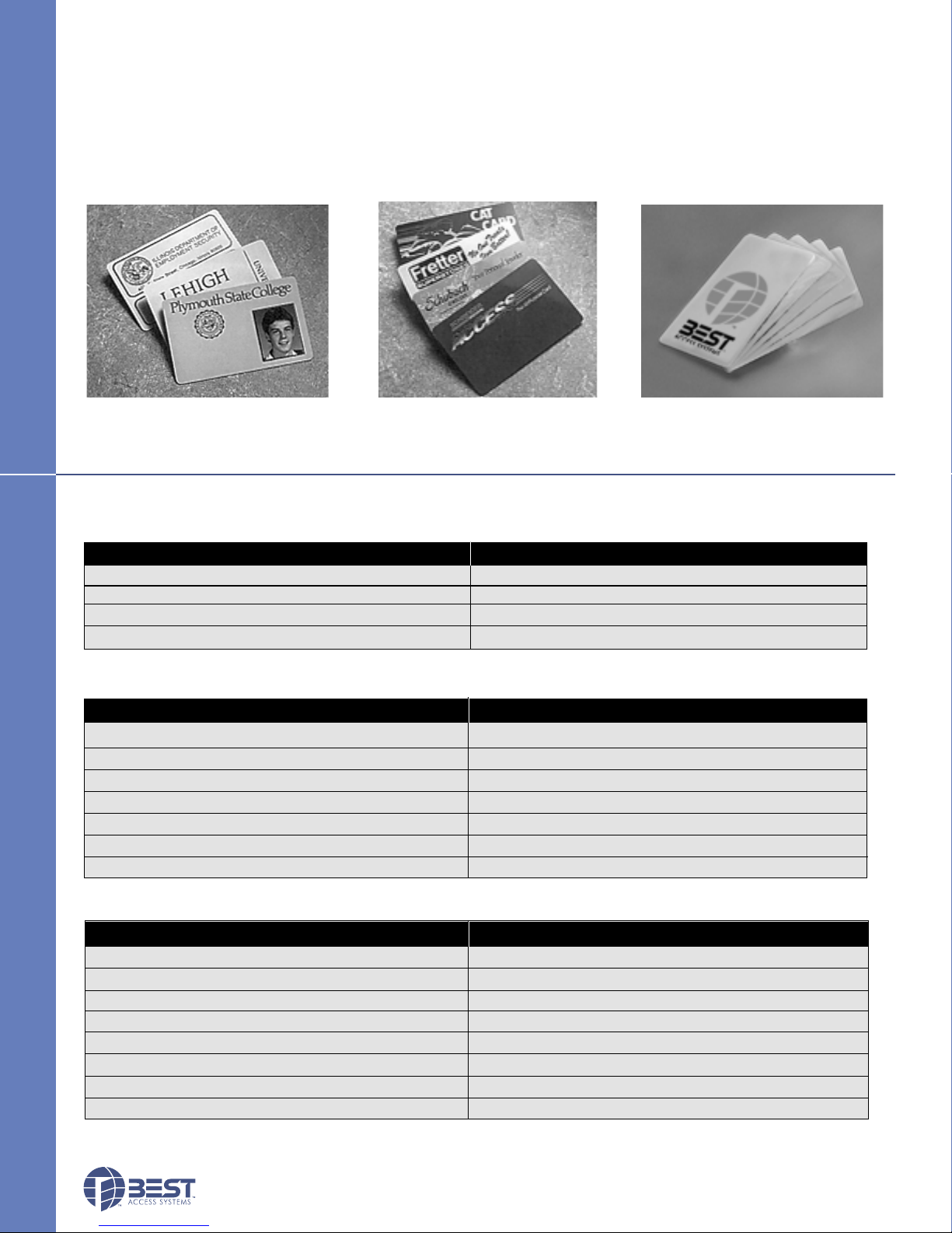
STANDARD CARDS
Card Specifications:
• Standard credit card size
• ISO standard .030" ±.003 thickness (PVC or Polyester)
• High coercivity ABA 3 tracks
STANDARD CARDS
Photo I.D. Card
ORDER PROCEDURE
BV SERIES SYSTEM
Programming Cable BASD – CAB
Mag Stripe Encoder BASD – MSE
Smart Card Encoder BASD – SCE
B.A.S.I.S. Software BAS – SWS – V
BV SERIES ACCESSORIES
ORDER PROCEDURE
McGard™ Battery Door Screw (Specify Finish) VPD – HS – SCRW
McGard™ Driver Bit VPD – HS – DRVR
Standard Driver Bit VPD – T15
Cleaning Cards (Box of 50) VPD – CLN
Electrostatic Discharge (ESD) Kit VPD – ESD
Replacement Battery Pack VPD – BB
Extended Battery Pack VPD – EXBB
Custom Graphics Card
Best Serialized Cards
Magnetic Strip / Proximity /
Part Description Catalog Number
(not shown)
Part Description Catalog Number
Smart Card
BV SERIES CARDS AND CARD OPTIONS
Part Description Catalog Number
PVC - (Box of 500) VPA – PVC
Polyester - (Box of 500) VPA – POLY
Photo Identification/Custom Graphics* VPA – CUST
HID ProxCard® II Proximity Card 1326* VPA – HID – 1326
HID DuoProx® II Proximity Card 1336* VPA – HID – 1336
Motorola Image 30™Proximity Card ISO-30+* VPA – MOT – ISO30
Motorola LifeTime™Proximity Card ASC-121T+* VPA – MOT – ASC121T
Smart Card®* VPA – SC
Special quote; contact local Best Access Systems office
*
10
STAND-ALONE EL
Page 10
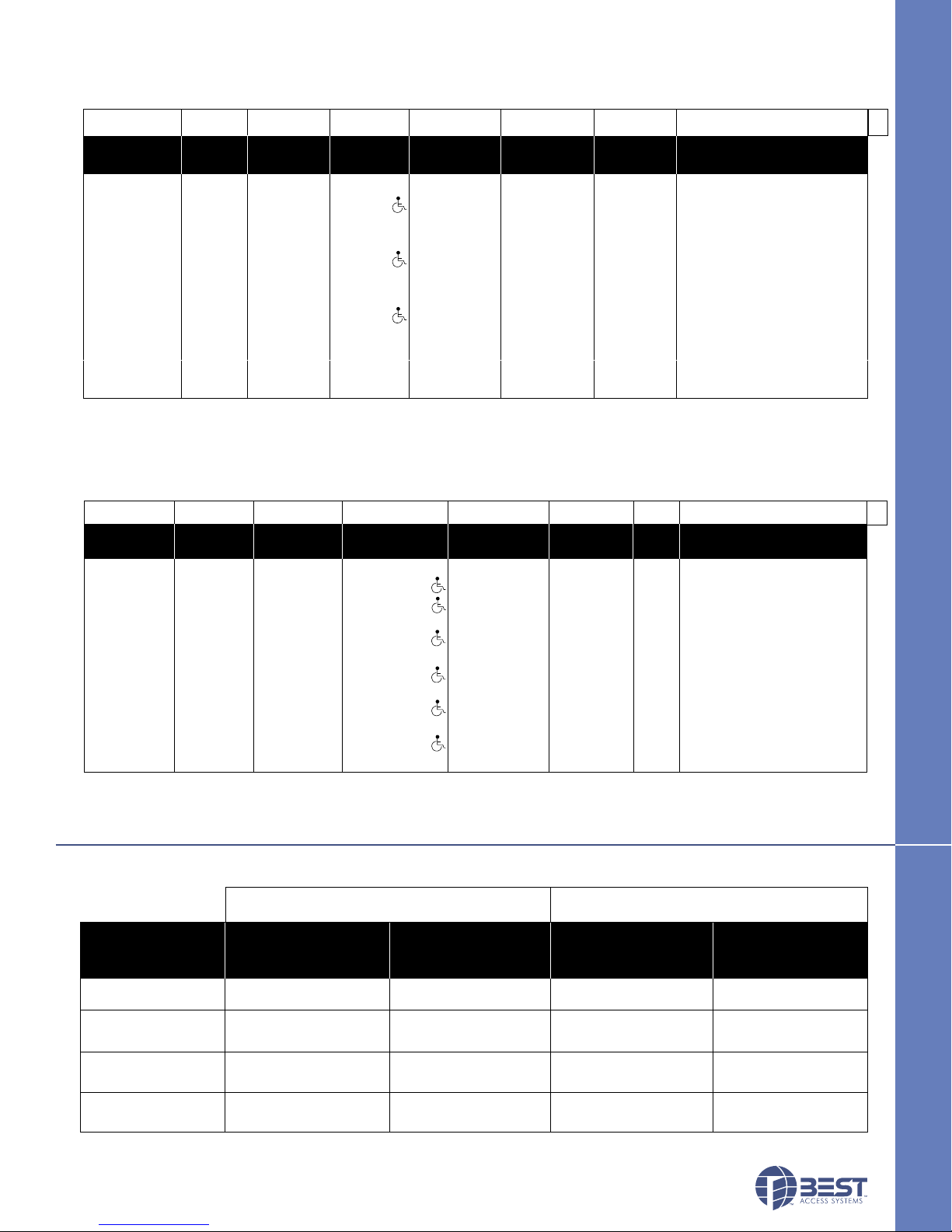
ORDER PROCEDURE
KBV
93KBV 7 DV 14 MS STK 626 **
Series Core Function Lever Trim Strike Finishes*** Options
Housing Code Style Style Package
93KBV–2 3/4" 7– 7 pin DV– 14– curved MS–magnetic STK–standard *605 *606 AL– abrasive lever (N/A 613)
94KBV–3 3/4" * housing cylindrical return stripe S3–ANSI *611 *612 EXBB– extended battery pack
95KBV–5" * latch w/key 15– contour PM–proximity *613 *625 FM– free motion †
override angle Motorola 626 690 SH– security head screws*
return PH– proximity TL– tactile lever*(#14,#16)
16– curved HID Thick door-specify if other
no return DV–dual than 13/4" *
validation 3/4–3/4" throw *
Proximity Reader Only
ABA, 26 bit Weigand, 37 bit
Weigand
(Page 7) (Page 7)
* Extra cost option.
** Must specify key mark and number of patented/standard keys.
*** Escutcheons and levers are made from a zinc alloy and have been plated to be equivalent in appearance to the finishes listed.
† Lower cost option.
(Page 6) (Page 6 )(Page 6)
(Page 7)
HBV
ORDER PROCEDURE
35HBV 7 FV 14 MS 626 RH **
Series Core Function Lever Trim Finishes*** Hand Options
35HBV– lever 0– keyless EV– latch 3– solid tube MS–magnetic * 605 * 606 RH AL– abrasive lever (N/A 613)
* Extra cost option.
** Must specify key mark and number of patented/standard keys.
*** Escutcheons are made from a zinc alloy and have been plated to be equivalent in appearance to the finishes listed.
Reader Cylinder Mortise Cylinder Mortise
Housing Code Style Style
7– 7 pin w/key w/ return stripe * 611 * 612 RHRB EXBB– extended battery pack
housing FV– deadbolt 12–solid tube PM– proximity, * 613 * 625 LH SH– security head screws*
w/key NV– latch 14– curved Motorola 626 629 LHRB Thick door– specify if other
w/o key w/return PH– proximity, 630 690 than 13/4" *
LV– deadbolt 15– contour w/ HID TL– tactile lever*(#14,#16)
w/o key angle return DV– dual Proximity Reader Only
16– curved validation ABA, 26 bit Weigand, 37 bit
no return Weigand
17– gullwing no
return
(Page 5) (Page 5) (Page 4) (Page 4) (Page 7)
BATTERY LIFE CHART
Standard Battery Pack Extended Battery Pack
Cycles, Years Cycles, Years Cycles, Years Cycles, Years
Magstripe
Smart Card
Proximity
Dual Val
65,000 / 2–5 yrs.
62,000 / 2–5 yrs.
50,000 / 2–3.5 yrs.
65,000 / 2–5 yrs.
130,000 / 3–5 yrs.
110,000 / 3–5 yrs.
75,000 / 2–3.5 yrs.
130,000 / 3–5 yrs.
ECTRONIC LOCKS
130,000 / 3–5 yrs.
120,000 / 3–5 yrs.
95,000 / 2–5 yrs.
130,000 / 3–5 yrs.
250,000 / 4–5 yrs.
225,000 / 4–5 yrs.
145,000 / 3–5 yrs.
250,000 / 4–5 yrs.
BATTERY LIFE CHART
11
Page 11

Planning the installation
Installation Instructions for
B.A.S.I.S. Cylindrical Locks
Contents
These installation instructions describe how to install your
B.A.S.I.S. G (93KG–95KG) or B.A.S.I.S. V (93KBV–95KBV)
Cylindrical Lock. The following topics are covered.
Planning the installation................................................1
Preparing the door and door jamb ................................2
Installing the lock ............................................................6
Completing the installation............................................9
Site survey
Use the following survey to record information about the
installation site. You need this information to determine
how to prepare the door for the lock.
Door information
Door handing and bevel:
❑ Left hand (LH)
❑ Left hand, reverse bevel (LHRB)
❑ Right hand (RH)
❑ Right hand, reverse bevel (RHRB)
Door thickness:
Environment information
Ambient temperature:
❑ Is within specifications. See the tables below.
This product meets the following Locked Door Outdoor
test requirements for ANSI/BHMA 156.25:
Side of door Range
Inside +66°F to +74°F (+19°C to +23°C)
Outside –31°F to +151°F (–35°C to +66°C)
This product meets the following Full Indoor test
requirements for ANSI/BHMA 156.25:
Side of door Range
Inside and outside +32°F to +120°F (0°C to +42°C)
inches (1 3/4″ to 2 1/4″)
Components checklist
Use the following checklist to make sure that you have the
items necessary to install your B.A.S.I.S. Cylindrical Lock.
Components provided in the box:
❑ Chassis with outside lever and outside rose liner
assembly
❑ Inside escutcheon assembly
❑ Battery compartment door
❑ Battery pack
❑ Inside rose liner
❑ Outside escutcheon assembly
❑ Inside lever
❑ Throw member package
❑ Latch
❑ Plastic bushing package
❑ Escutcheon screw package
❑ Strike package
❑ Bar code ID sticker (for your records)
❑ Temporary operator card
❑ Installation template and instructions
Other components:
❑ Core
❑ Control key
Special tools checklist
Use the following checklist to make sure that you have the
special tools necessary to install your B.A.S.I.S. Cylindrical
Lock.
❑ KD303 Drill jig
❑ T15 TORX® bit driver
❑ KD325 Strike plate locating pin
❑ KD315 Faceplate marking chisel
†
† TORX is a registered trademark of the Camcar
Division of Textron.
BEST ACCESS SYSTEMS
Indianapolis, Indiana
1
Page 12
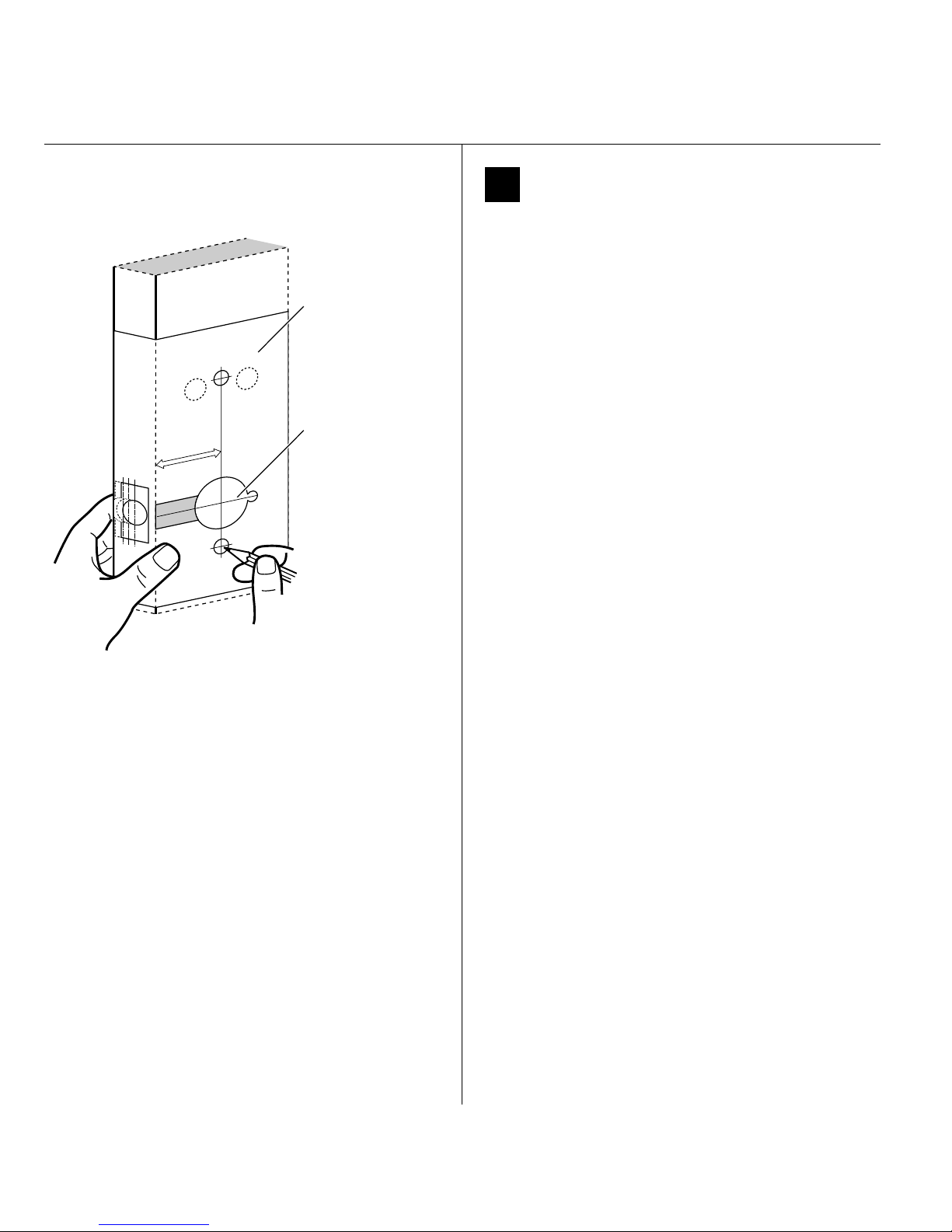
Installation Instructions for B.A.S.I.S. Cylindrical Locks
Installation template
Horizontal centerline
of lever
Figure 1 Positioning the template
Preparing the door and door jamb
1 Position template and mark drill points
Note: If the door is a fabricated hollow metal door,
determine whether it is properly reinforced to support
the lock. If door reinforcement is not adequate, consult
the door manufacturer for information on proper
reinforcement. For dimensions for preparing metal
doors, see the G01 and G02 Templates—Installation
Specifications for 93KG and 93KBV Cylindrical Locks.
Note: If the door is a LH or RH door, mark the inside of
the door. If the door is a LHRB or RHRB door, mark the
outside of the door.
For uncut doors and frames
1 Measure and mark the horizontal centerline of the
lever (the centerline for the chassis hole) on the door
and door jamb. Mark the vertical centerline of the door
edge.
Note: The recommended height from the floor to the
centerline of the lock is 38″.
2 Fold the G05 Template—Installation Template for 93KG
and 93KBV Cylindrical Locks on the dashed line and
carefully place it in position on the high side of the
door bevel.
Note: For steel frame applications, align the template’s
horizontal centerline for the latch with the horizontal
centerline of the frame’s strike preparation.
3 Tape the template to the door.
4 Center punch the necessary drill points. Refer to the
instructions on the template.
2
For doors with standard cylindrical preparation
1 Fold the G05 Template—Installation Template for 93KG
and 93KBV Cylindrical Locks on the dashed line.
Looking through the hole from the opposite side of
the door, align the template so that you see the
template outline of the 2 1/8″diameter chassis hole.
2 Tape the template to the door.
3 Center punch the necessary drill points. Refer to the
instructions on the template.
BEST ACCESS SYSTEMS
Indianapolis, Indiana
Page 13
Installation Instructions for B.A.S.I.S. Cylindrical Locks
Installation Instructions for B.A.S.I.S. Cylindrical Locks
Preparing the door and door jamb Components checklist
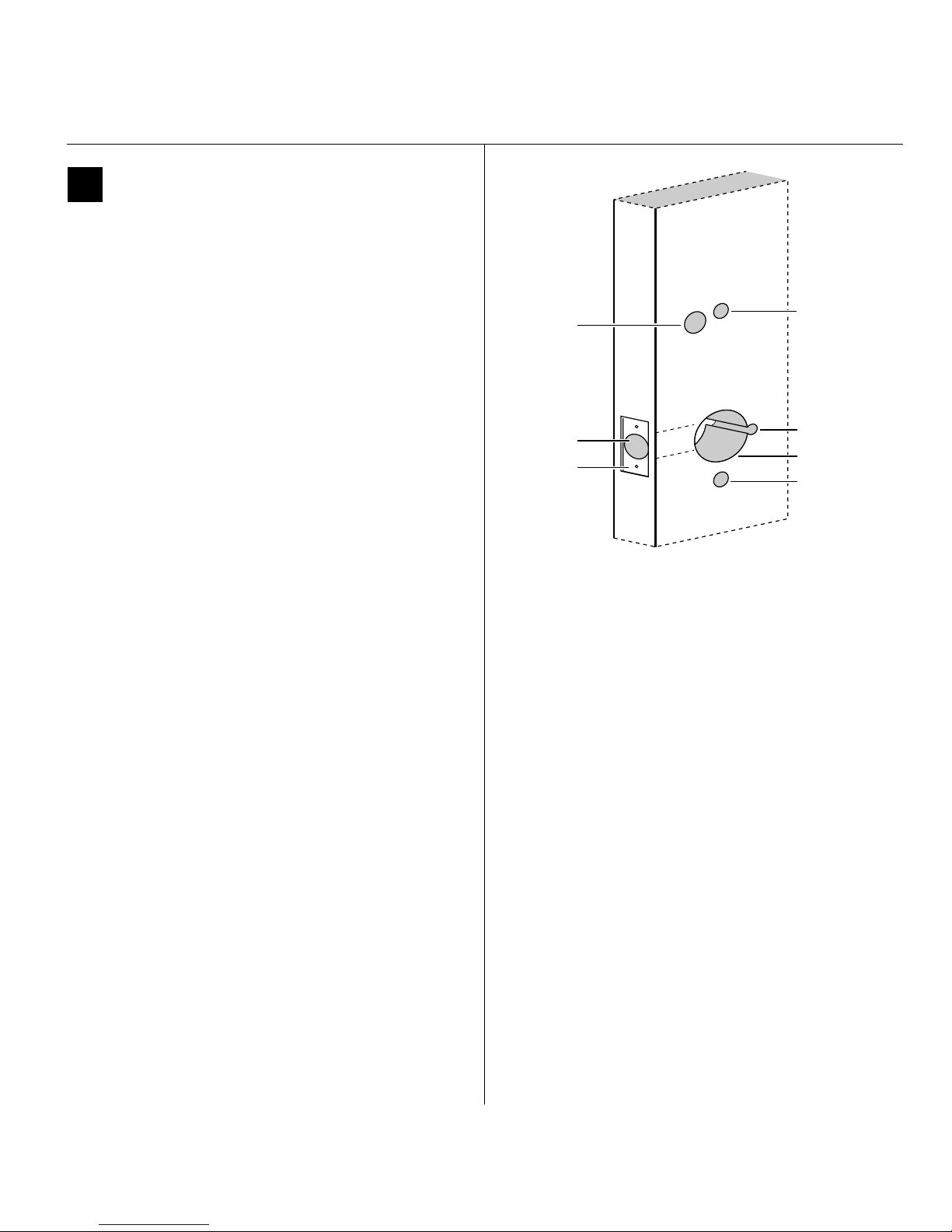
2 Drill holes and mortise for latch face.
1 Drill the holes listed below:
■ upper and lower trim holes
—5/8″ diameter
— through door
■ harness hole
—3/4″ diameter
— through door
— location based on handing
■ motor wire hole
—7/16″ diameter
— through door
— before drilling chassis hole
■ chassis hole
—2 1/8″ diameter
— through door
— after drilling motor wire hole
■ latch hole
—1″ diameter
— meets chassis hole
Harness
hole
Latch hole
Latch face
mortise
Inside of door
Figure 2 Drilling holes and mortising for the latch face
Upper trim hole
Motor wire hole
Chassis hole
Lower trim hole
Note 1: To locate the center of a hole on the opposite
side of the door, drill a pilot hole completely through the
door.
Note 2: For holes through the door, it is best to drill
halfway from each side of the door to prevent the door
from splintering.
2 Mortise the edge of the door to fit the latch face.
3 Drill the holes for the screws used to install the latch.
BEST ACCESS SYSTEMS
Indianapolis, Indiana
3
Page 14
Installation Instructions for B.A.S.I.S. Cylindrical Locks
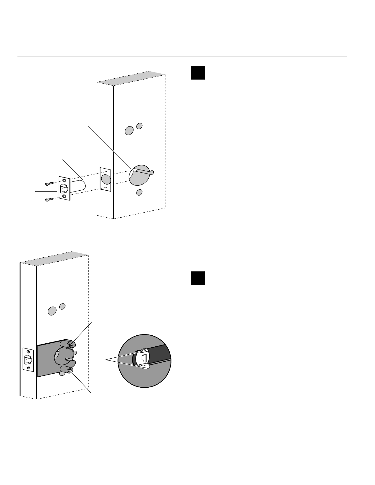
Chassis hole
Location of latch
tube prongs
Latch
Preparing the door and door jamb
3 Install latch
1 Install the latch in the door.
Note: The latch tube prongs should be centered and
should project into the chassis hole.
2 Check that the door swings freely.
Figure 3 Installing the latch in the door
Drill upper through-bolt hole.
Latch
tube
prongs
Drill lower through-bolt hole.
Inside of door
4 Use drill jig to drill through-bolt holes
1 Press the drill jig (KD303) onto the door, engaging it
with the latch tube prongs (see the close-up in
Figure 4). Make sure the front edge of the jig is parallel
with the door edge.
2 Drill the through-bolt holes (5/16″diameter) halfway
into the door.
3 Turn over the drill jig and repeat steps 1 and 2 from the
opposite side of the door.
Note: Replace the drill jig after 10 door preparations.
Inside of door
Figure 4 Installing the drill jig and drilling the
through-bolt holes
4
BEST ACCESS SYSTEMS
Indianapolis, Indiana
Page 15
Preparing the door and door jamb
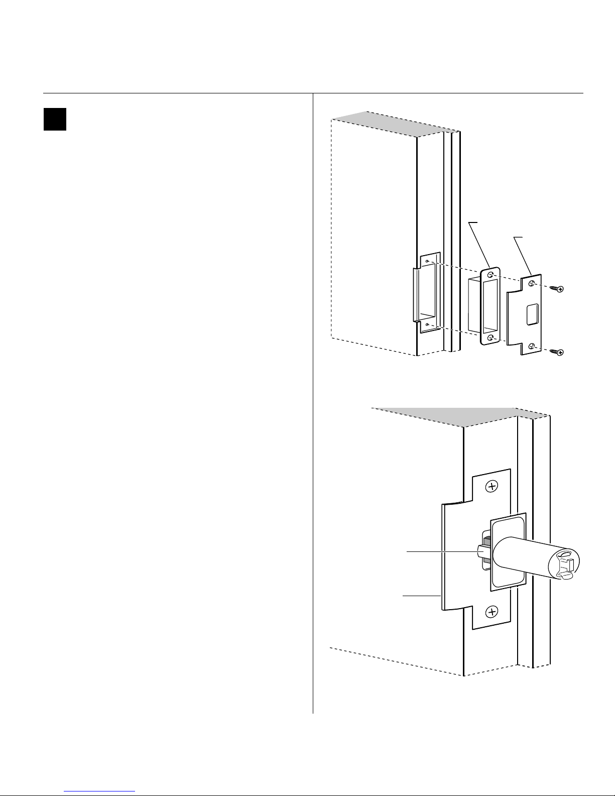
5 Install strike box and strike plate
1 In alignment with the center of the latchbolt, mortise
the door jamb to fit the strike box and strike plate.
2 Drill the holes for the screws used to install the strike
box and strike plate.
3 Insert the strike box and secure the strike with the two
screws provided.
4 Check the position of the deadlocking plunger against
the strike plate.
Caution: The deadlocking plunger of the latchbolt
must make contact with the strike plate, as shown
in Figure 5b. The plunger deadlocks the latchbolt
and prevents someone from forcing the latch
open when the door is closed.
Installation Instructions for B.A.S.I.S. Cylindrical Locks
Installation Instructions for B.A.S.I.S. Cylindrical Locks
Strike box
Strike plate
Door jamb
Figure 5a Installing the strike box and strike plate
Deadlocking
plunger
Strike plate
Door jamb
Figure 5b Aligning the deadlocking plunger with the
BEST ACCESS SYSTEMS
Indianapolis, Indiana
strike plate
5
Page 16
Installation Instructions for B.A.S.I.S. Cylindrical Locks
Installing the lock
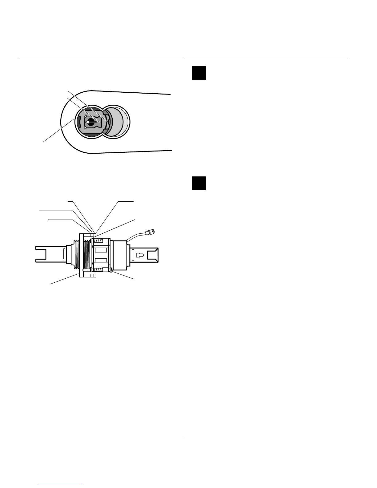
6 Remove outside lever
Lever keeper
Insert screwdriver
blade here.
Figure-8
core hole
Figure 6 Removing the outside lever
2 1/4″ groove
2″
1 3/4″
Throughbolt stud
Hub face
1 Insert the control key into the core and rotate the key
15 degrees to the right.
2 Insert a flat blade screwdriver into the figure-8 core
hole and into the lever.
3 Press the screwdriver blade in the direction of the
arrow in Figure 6.
Note: You cannot remove the lever if the screwdriver
blade is inserted too far past the keeper.
4 Slide the lever off of the sleeve.
7 Adjust for door thickness
1 Determine the door’s thickness.
2 Pull the rose locking pin and rotate the outside rose
liner until the proper groove on the through-bolt stud
lines up with the hub face.
Note 1: Make sure that the locking pin fully locks into
the rose liner.
Note 2: The lockset fits doors 1 3/4″ to 2 1/4″ thick.
Outside
rose liner
Rose locking
pin
Figure 7 Adjusting the rose liner for the door thickness
6
BEST ACCESS SYSTEMS
Indianapolis, Indiana
Page 17
Installing the lock
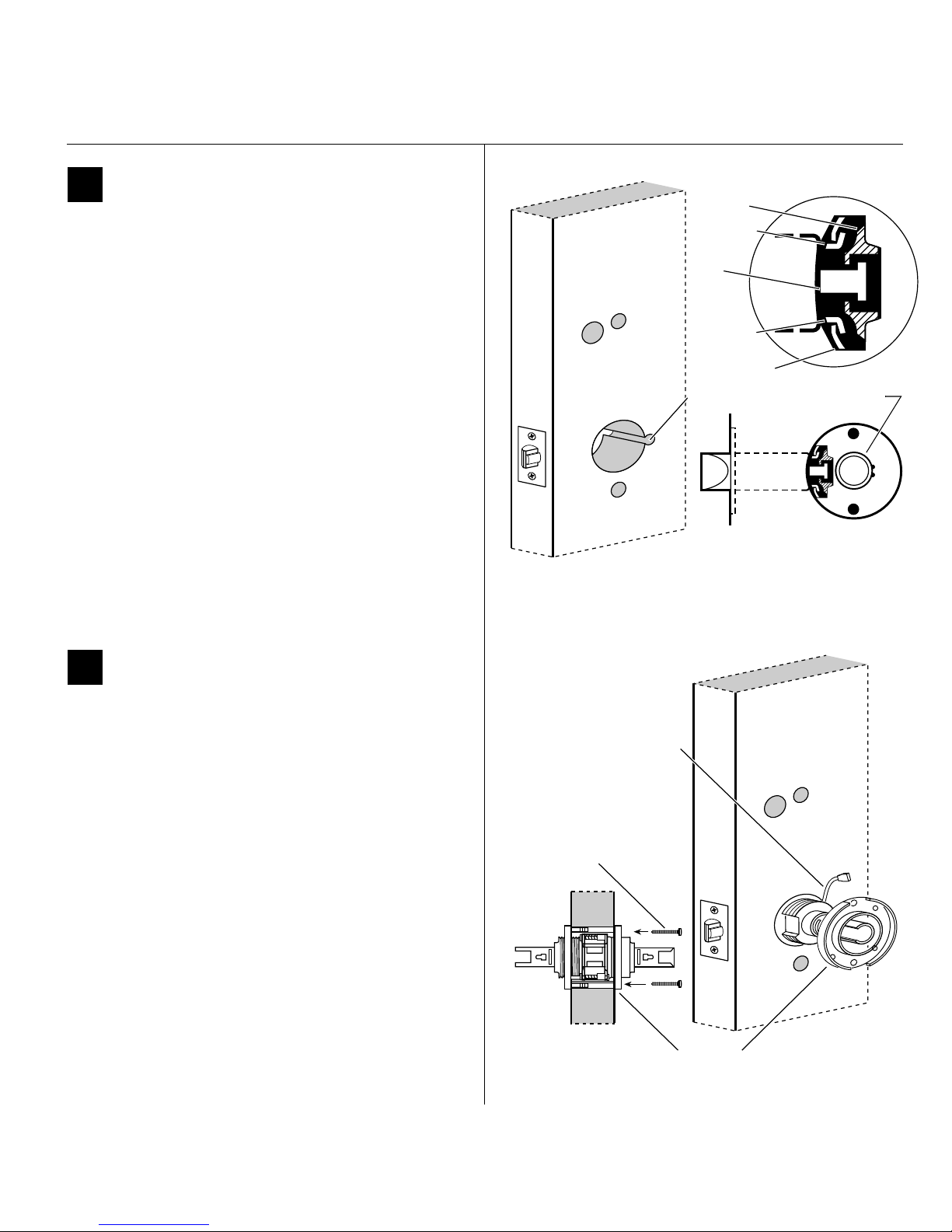
8 Install lock chassis and engage
retractor in latch
From the outside of the door, insert the lock chassis
into the 2 1/8″ chassis hole, routing the motor wire
through the notch.
Caution: Make sure that the latch tube prongs
engage the chassis frame and that the latch
tailpiece engages the retractor.
Installation Instructions for B.A.S.I.S. Cylindrical Locks
Installation Instructions for B.A.S.I.S. Cylindrical Locks
Retractor
Latch tube
prong
Latch
tailpiece
Latch tube
prong
Chassis frame
9 Install through-bolts and inside rose
liner
1 Place the inside rose liner on the chassis, aligning the
holes in the rose liner with the holes prepared in the
door.
Caution: Make sure that there is clearance for the
motor wire between the rose liner and the door.
2 Install the through-bolts through the rose liner and
door in the top and bottom holes.
3 Tighten the rose liner on the door with the
through-bolts.
Notch
Inside of door
Figure 8 Installing the lock chassis and engaging the
retractor in the latch
Motor wire
Through-bolt
Chassis
Figure 9 Installing the through-bolts and rose liner
BEST ACCESS SYSTEMS
Indianapolis, Indiana
Rose liner
Inside of door
7
Page 18
Installation Instructions for B.A.S.I.S. Cylindrical Locks
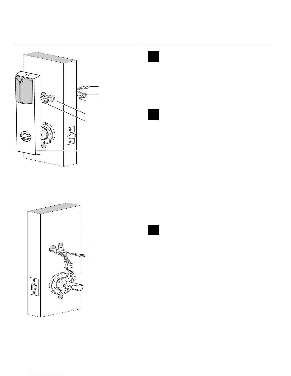
Battery connector
Motor connector
Upgrade
connector
a
H
n
r
e
s
s
h
e
l
o
Bushing
Outside escutcheon
Outside of door
Figure 11 Feeding the wire harness connectors through
the harness hole
Installing the lock
10 Remove backup battery tab
Caution: For the lock to operate properly, you
must remove the backup battery tab.
1 Locate the backup battery tab on the inside of the
outside escutcheon.
2 Pull down on the tab and remove it from the outside
escutcheon to turn on the backup battery.
11 Route wire harness and position
outside escutcheon
1 Insert the two bushings into the harness hole on each
side of the door, as shown in Figure 11 and Figure 12.
2 From the outside of the door, feed the upgrade
connector, and then the motor connector and battery
connector, through the harness hole.
Caution: When routing the connectors, make sure
the wire harness is not routed across any sharp
edges or over any surface that could damage its
sleeving or wire insulation.
3 Temporarily rest the outside escutcheon on the door
by inserting the trim studs into the trim holes.
Note: You can temporarily install the outside lever to
hold the outside escutcheon in place. See task 15 on
page 10.
Inside of door
Figure 12 Making the motor connection
8
Bushing
Upgrade cable
Motor connection
BEST ACCESS SYSTEMS
12 Make motor connection
Indianapolis, Indiana
From the inside of the door, connect the motor
connector from the chassis to its mating connector on
the wire harness.
Note: The upgrade cable is used for reprogramming the
lock’s firmware without removing the lock from the door.
This cable does not connect to a mating lock connector.
Caution: When making the motor connection,
make sure:
■ there are no loose wire connections where the
wires are inserted into the connectors
■ the connectors are firmly mated.
Wire connection Colors
Motor Yellow
Gray
No. of
wires
No. of
pins
22
Page 19
Installing the lock
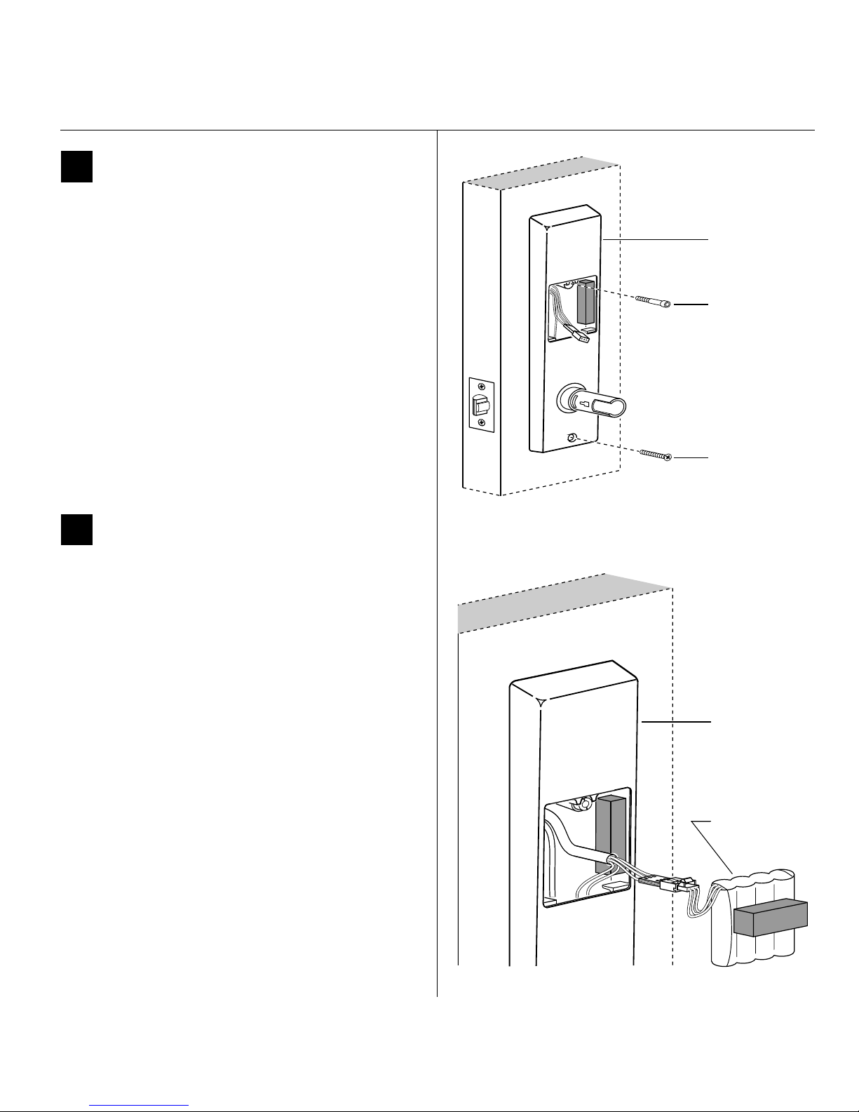
13 Secure escutcheons
1 Position the inside and outside escutcheons on the
door.
2 Making sure that the escutcheons do not pinch
the wires, secure the escutcheons to the door—but
do not tighten. Use the combination mounting screw
at the upper trim hole and the standard mounting
screw at the lower trim hole.
Installation Instructions for B.A.S.I.S. Cylindrical Locks
Installation Instructions for B.A.S.I.S. Cylindrical Locks
Inside escutcheon
Combination
mounting screw
Standard
mounting screw
14 Install battery pack
1 Connect the battery pack to the battery connector on
the wire harness inside the battery compartment.
Wire
connection
Battery Red w/white stripe
Color
White
Black w/white stripe
Caution 1: When routing the battery wires, make
sure the wires are not routed across any sharp
edges or over any surface that could damage their
sleeving or wire insulation.
Caution 2: When connecting the battery pack,
make sure:
■ there are no loose wire connections where the
wires are inserted into the connectors
■ the connectors are firmly mated.
2 Place the battery pack inside the battery compartment
so that the foam will face the battery compartment
door.
No. of
wires
No. of
pins
33
Inside of door
Figure 13 Securing the escutcheons
Inside escutcheon
Battery pack
Figure 14 Connecting the battery pack
BEST ACCESS SYSTEMS
Indianapolis, Indiana
9
Page 20

Installation Instructions for B.A.S.I.S. Cylindrical Locks
Outside of door
Figure 15 Installing the levers
Completing the installation
15 Install inside and outside levers
Note: To use a core and throw member from a
manufacturer other than BEST with a B.A.S.I.S. Lock, see
the Installation Instructions for 9K Non-
interchangeable Cores & Throw Members (T56093).
Skip task 15 and task16.
For the inside and outside levers
1 With the handle pointing toward the door hinges,
position a lever on the outside sleeve and push firmly
on the lever until it is seated. Repeat, placing the other
lever on the inside sleeve.
2 Tighten the escutcheon mounting screws.
3 Turn the levers to check that they operate smoothly.
Core
Blocking
plate
Throw
member
Figure 16a Installing the blocking plate and throw
member
Throw
member
Core
Control
key
Figure 16b Installing the core
16 Install core and throw member
1 Install the blocking plate onto the throw member.
Caution: You must use the blocking plate to
prevent unauthorized access.
2 Insert the control key into the core and rotate the key
15 degrees to the right.
3 Insert the throw member into the core.
4 Insert the core and throw member into the lever with
the control key.
5 Rotate the control key 15 degrees to the left and
withdraw the key.
Caution: The control key can be used to remove
cores and to access doors. Provide adequate
security for the control key.
10
BEST ACCESS SYSTEMS
Indianapolis, Indiana
Page 21
Completing the installation
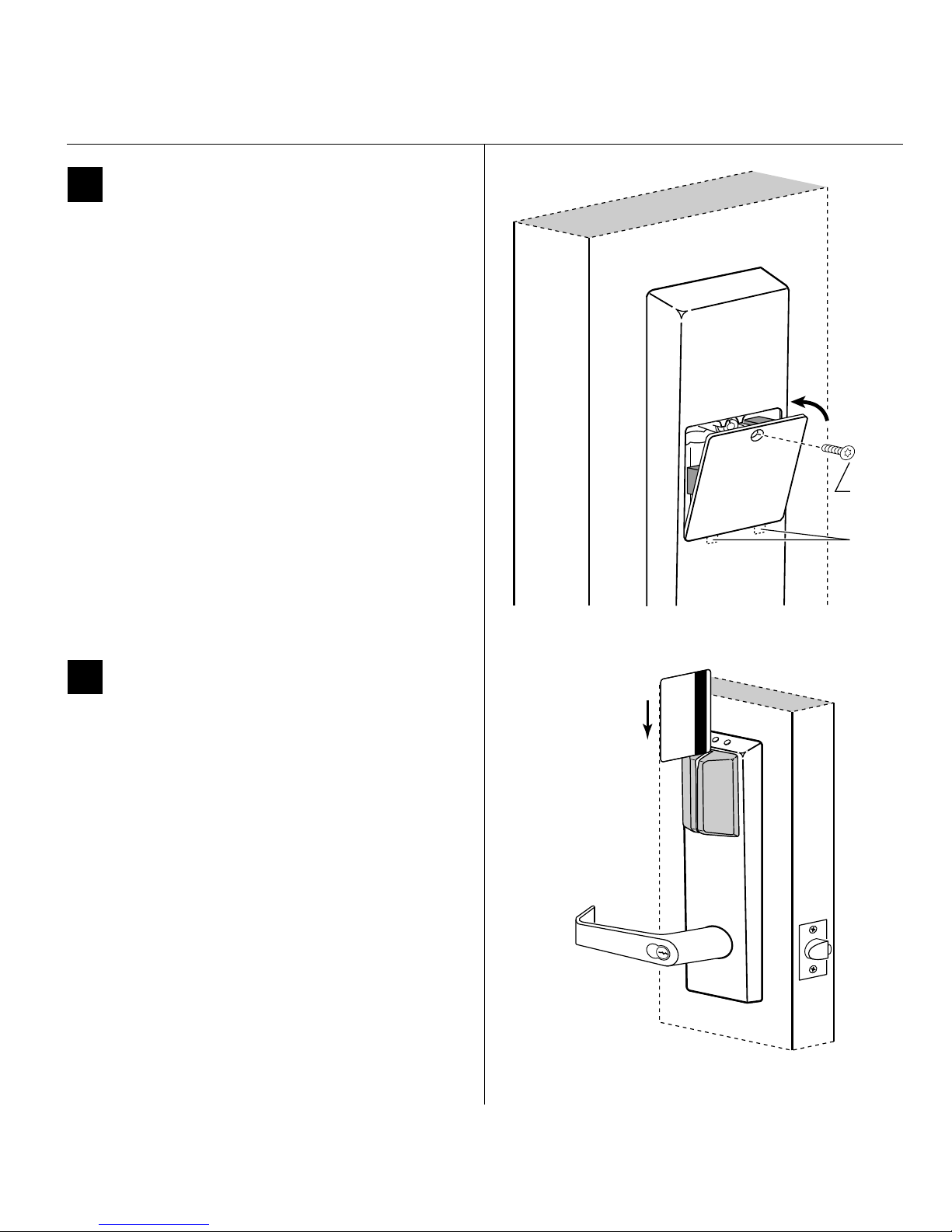
17 Install battery compartment door
1 Making sure that the battery compartment door
does not pinch any wires, insert the tabs of the
battery compartment door into its mating slots and
swing the door closed.
2 Use a T15 TORX bit driver to secure the battery
compartment door with the security screw. Tighten
firmly.
Installation Instructions for B.A.S.I.S. Cylindrical Locks
Installation Instructions for B.A.S.I.S. Cylindrical Locks
Security
screw
Tabs
18 Test lock
To test the lock for proper operation, use the temporary
operator card that came with the lock. This card is for
temporary use only. After permanent cards have been
programmed for the lock, the temporary card should be
deleted.
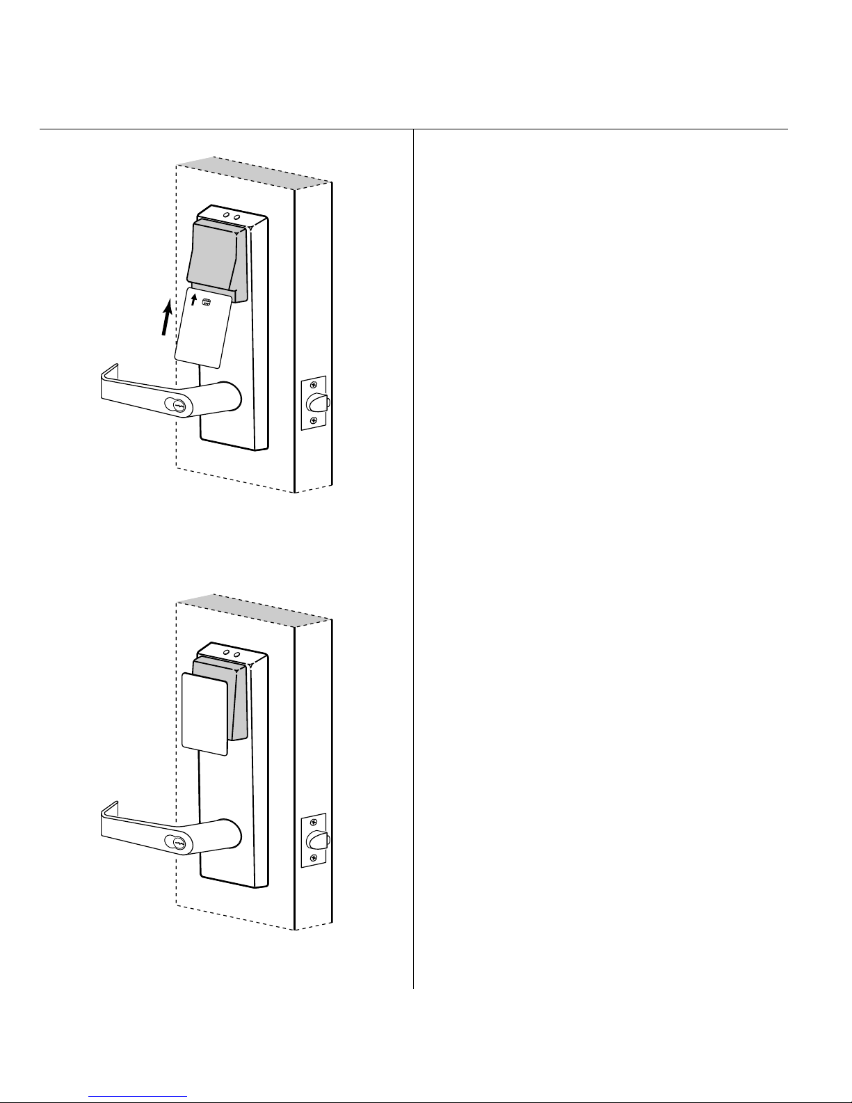
For locks with magnetic stripe card readers
1 With the magnetic stripe facing towards the right,
swipe the temporary operator card, as shown in
Figure 18a.
The green light flashes and the locking mechanism
unlocks.
2 Turn the lever and open the door.
Figure 17 Installing the access door
Figure 18a Using the temporary operator card with a
magnetic stripe card reader
BEST ACCESS SYSTEMS
Indianapolis, Indiana
11
Page 22
Installation Instructions for B.A.S.I.S. Cylindrical Locks
Operator
Temporary
Completing the installation
For locks with smart card readers
1 With the writing facing towards you, insert and
remove the temporary operator card, as shown in
Figure 18b.
The green light flashes and the locking mechanism
unlocks.
2 Turn the lever and open the door.
Figure 18b Using the temporary operator card with a
smart card reader
Temporary
Operator
For locks with proximity card readers
1 Hold the temporary operator card within an inch of the
lock’s card reader, as shown in Figure 18c.
The green light flashes and the locking mechanism
unlocks.
2 Turn the lever and open the door.
If the mechanism doesn’t unlock, refer to the
following table.
LEDs Sounder Access You should
—3 short
tones
Red
flashes
Green
flashes
— — Denied Check the battery
3 short
tones
— Denied Check the motor
Denied Use the card at a moderate
speed.
Denied Use the temporary
operator card provided
with the lock.
connection.
connection.
Figure 18c Using the temporary operator card with a
proximity card reader
12
For all locks
Insert and turn the key to unlatch the door.
BEST ACCESS SYSTEMS
Indianapolis, Indiana
© 2000 Best Lock Corporation dba Best Access Systems.
T63301/Rev B 1819347 ER-7991-12 June 2001
Page 23

Planning the installation
Installation Instructions for
B.A.S.I.S. Mortise Locks
Contents
These installation instructions describe how to install your
B.A.S.I.S. G (35HG) or B.A.S.I.S. V (35HBV) Mortise Lock.
The following topics are covered.
Planning the installation................................................1
Preparing the door and door jamb ................................2
Installing the lock ............................................................5
Completing the installation..........................................10
Site survey
Use the following survey to record information about the
installation site.
Lock information
Lock function:
❑ EV–Latch with key override
❑ With key override sensing
❑ FV–Deadbolt with key override
❑ With key override sensing
❑ LV–Deadbolt without key override
❑ NV–Latch without key override
Door information
Door handing and bevel:
❑ Left hand (LH)
❑ Left hand, reverse bevel (LHRB)
❑ Right hand (RH)
❑ Right hand, reverse bevel (RHRB)
Door thickness:
Environment information
Ambient temperature:
❑ Is within specifications. See the tables below.
This product meets the following Locked Door Outdoor
test requirements for ANSI/BHMA 156.25:
Side of door Range
Inside +66°F to +74°F (+19°C to +23°C)
Outside –31°F to +151°F (–35°C to +66°C)
inches (1 3/4″ to 3″)
†
†
This product meets the following Full Indoor test
requirements for ANSI/BHMA 156.25:
Side of door Range
Inside and outside +32°F to +120°F (0°C to +42°C)
Components checklist
Use the following checklist to make sure that you have the
items necessary to install your B.A.S.I.S. Mortise Lock.
Components provided in the box:
❑ Mortise case assembly
❑ Mortise case faceplate
❑ Inside escutcheon assembly
❑ Battery compartment door
❑ Battery pack
❑ Outside escutcheon assembly
❑ Inside and outside mounting plates
❑ Inside lever
❑ Outside lever & spindle assembly
❑ Cylinder assembly (for EV and FV functions only)
❑ Screw package
❑ Plastic bushing package
❑ Escutcheon screw package
❑ Strike
❑ Strike box
❑ Bar code ID sticker (for your records)
❑ Temporary operator card
❑ Installation template and instructions
Other components:
❑ Core (for EV and FV functions only)
❑ Control key (for EV and FV functions only)
Special tools checklist
Use the following checklist to make sure that you have the
special tools necessary to install your B.A.S.I.S. Mortise
Lock.
❑ T15 TORX® bit driver
❑ ED211 cylinder wrench (for EV and FV functions only)
‡
† Key override sensing is optional for 35HG and
standard for 35HBV.
‡ TORX is a registered trademark of the Camcar
Division of Textron.
BEST ACCESS SYSTEMS
Indianapolis, Indiana
1
Page 24
Installation Instructions for B.A.S.I.S. Mortise Locks
Preparing the door and door jamb
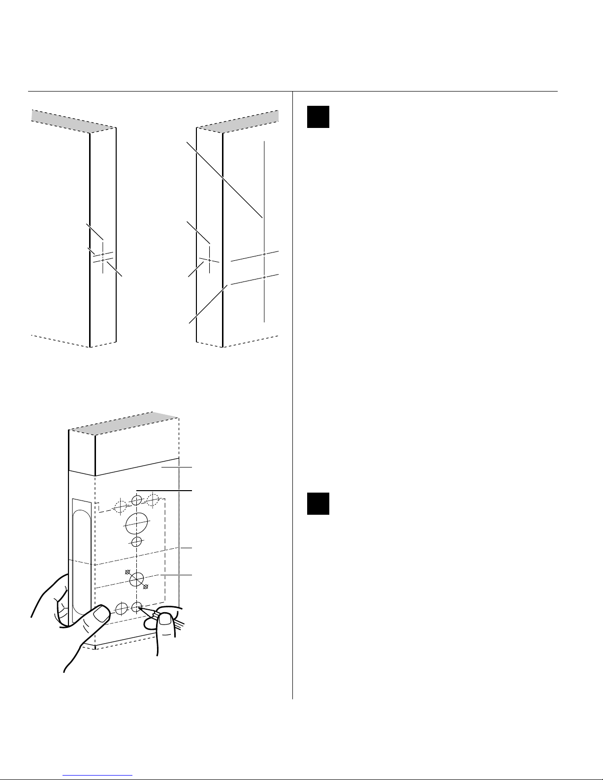
1 Mark centerlines
Vert. centerline
of lock
Vert. centerline
of strike
Horz. centerline
of strike
Door jamb
Vert. centerline
of door’s edge
Horz. centerline
of lock
Horz. centerline
of lever
(38″ from floor
recommended)
Figure 1 Marking the centerlines
Door
Installation template
Note: If the door is a fabricated hollow metal door,
determine whether it is properly reinforced to support
the lock. If door reinforcement is not adequate, consult
the door manufacturer for information on proper
reinforcement. For dimensions for preparing metal
doors, see the G03 Template—Installation
Specifications for 35HG and 35HBV Mortise Locks.
1 On the door, measure and mark the height of the
centerline of the lever from the floor (38″
recommended). On both sides of the door, on the
door’s edge, and on the door jamb, mark the
horizontal centerline of the lock 1 1/2″ above the
centerline of the lever.
Note: If the door is a LH or RH door, mark the inside of
the door. If the door is a LHRB or RHRB door, mark the
outside of the door.
2 On the door’s edge and door jamb, mark the vertical
centerline of the lock.
3 Measure and mark the backset (2 3/4″ standard) from
the vertical centerline on the door’s edge. On both
sides of the door, mark the vertical centerline of the
lock.
4 On the door jamb, mark the horizontal centerline of
the strike 3/8″ above the horizontal centerline of the
lock.
Vertical centerline
of lock
Horizontal centerline
of lock
Horizontal centerline
of lever
Figure 2 Positioning the template
2
2 Position template and mark drill points
1 Cut the G06 Template—Installation Template for 35HG
and 35HBV Mortise Locks along the dashed lines and
align the horizontal and vertical arrows with the
marked centerlines on the door.
2 Tape the template to the door.
3 Center punch the necessary drill points. Refer to the
instructions on the template.
BEST ACCESS SYSTEMS
Indianapolis, Indiana
Page 25
Preparing the door and door jamb
Installation Instructions for B.A.S.I.S. Mortise Locks
Installation Instructions for B.A.S.I.S. Mortise Locks
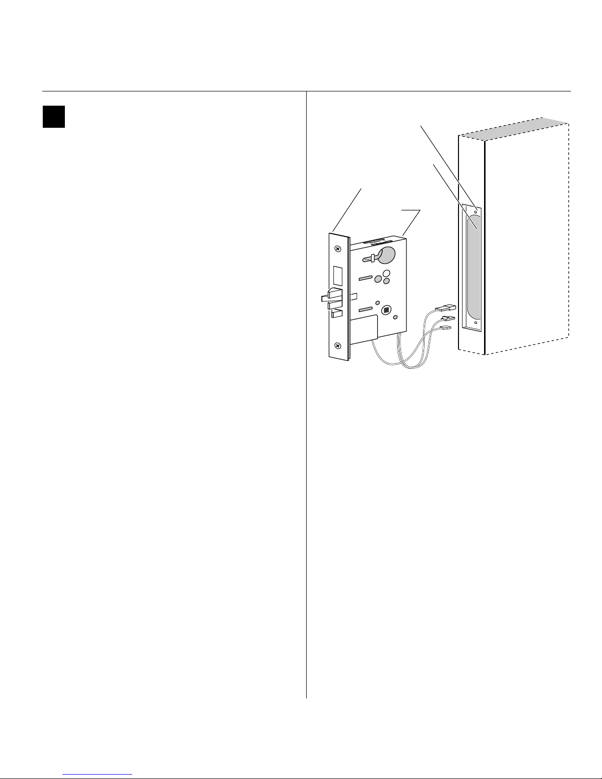
3 Mortise for lock case and faceplate
1 Mortise the edge of the door for the lock case.
Note: The mortise cavity depth of 4 5/8″ includes
clearance for wiring behind the mortise case.
2 Insert the lock in the mortise cavity.
3 Mark the outline of the lock faceplate.
4 Remove the lock. Mortise to fit the faceplate.
Lock faceplate
mortise
Lock case mortise
Lock faceplate
Lock case
Door
Figure 3 Mortising for the lock case and faceplate
BEST ACCESS SYSTEMS
Indianapolis, Indiana
3
Page 26
Installation Instructions for B.A.S.I.S. Mortise Locks
Preparing the door and door jamb
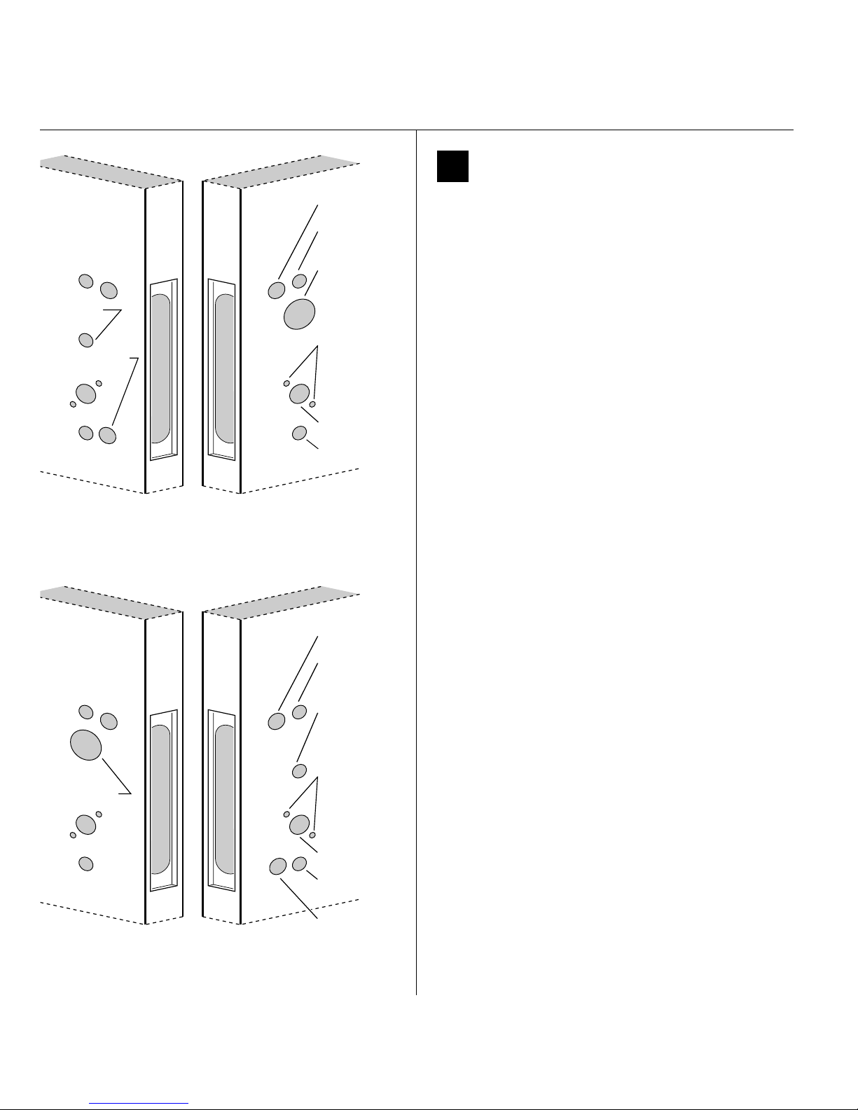
4 Drill holes
.125
Turn knob
hole
Sensor & motor
wire hole
Outside of RHRB doorInside of RH door
Figure 4a Drilling the RH and RHRB holes
.125
Cylinder hole
Harness hole
Upper trim
hole
Cylinder hole
Through-bolt
holes
Lever hole
Lower trim
hole
Harness hole
Upper trim
hole
Turn knob
hole
Through-bolt
holes
Lever hole
Lower trim
hole
Caution: Check for the correct lock function, hand,
and bevel before drilling.
Drill the holes listed below:
■ upper and lower trim holes
—5/8″ diameter
— through door
■ harness hole
—3/4″diameter
— through door
— location based on handing
■ cylinder hole
—1 3/8″diameter
— from outside into mortise cavity
— EV and FV functions only
■ turn knob hole
—5/8″ diameter
— from inside into mortise cavity
— FV and NV functions only
■ upper and lower through-bolt holes
—3/8″ diameter
— through door
■ lever hole
—7/8″ diameter
— through door
■ sensor & motor wire hole
—3/4″ diameter
— from inside into mortise cavity, approximately
1″ deep
Note 1: To locate the center of a hole on the opposite
side of the door, drill a pilot hole completely through the
door.
Note 2: For holes through the door, it is best to drill
halfway from each side of the door to prevent the door
from splintering.
Inside of LH doorOutside of LHRB door
Figure 4b Drilling the LH and LHRB holes
4
Sensor &
motor wire
hole
BEST ACCESS SYSTEMS
Indianapolis, Indiana
Page 27
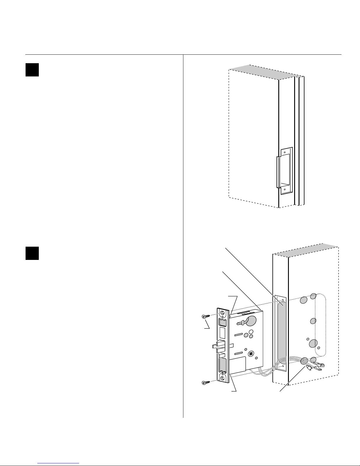
Preparing the door and door jamb
5 Mortise for strike box and strike plate
1 On the door jamb, locate the horizontal centerline of
the strike (3/8″ above the centerline of the lock), as
well as the vertical centerline of the strike.
2 Mortise the door jamb to fit the strike box and strike
plate.
3 Drill the holes for the screws used to install the strike
box and strike plate.
Installation Instructions for B.A.S.I.S. Mortise Locks
Installation Instructions for B.A.S.I.S. Mortise Locks
Door jamb
6 Install mortise case
1 Remove the faceplate from the mortise case.
2 Drill the holes for the case mounting screws.
3 Insert the mortise case into the mortise cavity, while
feeding the sensor and motor wires into the mortise
cavity and out the sensor & motor wire hole to the
inside of the door.
Note: If the armored front of the mortise case is not flush
with the door edge, remove the case and loosen the
screws at the top and bottom of the case. Adjust the
bevel of the armored front of the mortise case to match
the bevel of the door. Tighten the screws and insert the
mortise case back into the mortise cavity.
4 Secure the mortise case with the case mounting
screws.
Figure 5 Mortising the door jamb for the strike box and
strike plate
Mortise cavity
Mortise case
Bevel adjusting
screw
Case
mounting
screws
Location of bevel
adjusting screw
Sensor & motor
wire hole and wires
Inside of door
Figure 6 Installing the mortise case
BEST ACCESS SYSTEMS
Indianapolis, Indiana
5
Page 28
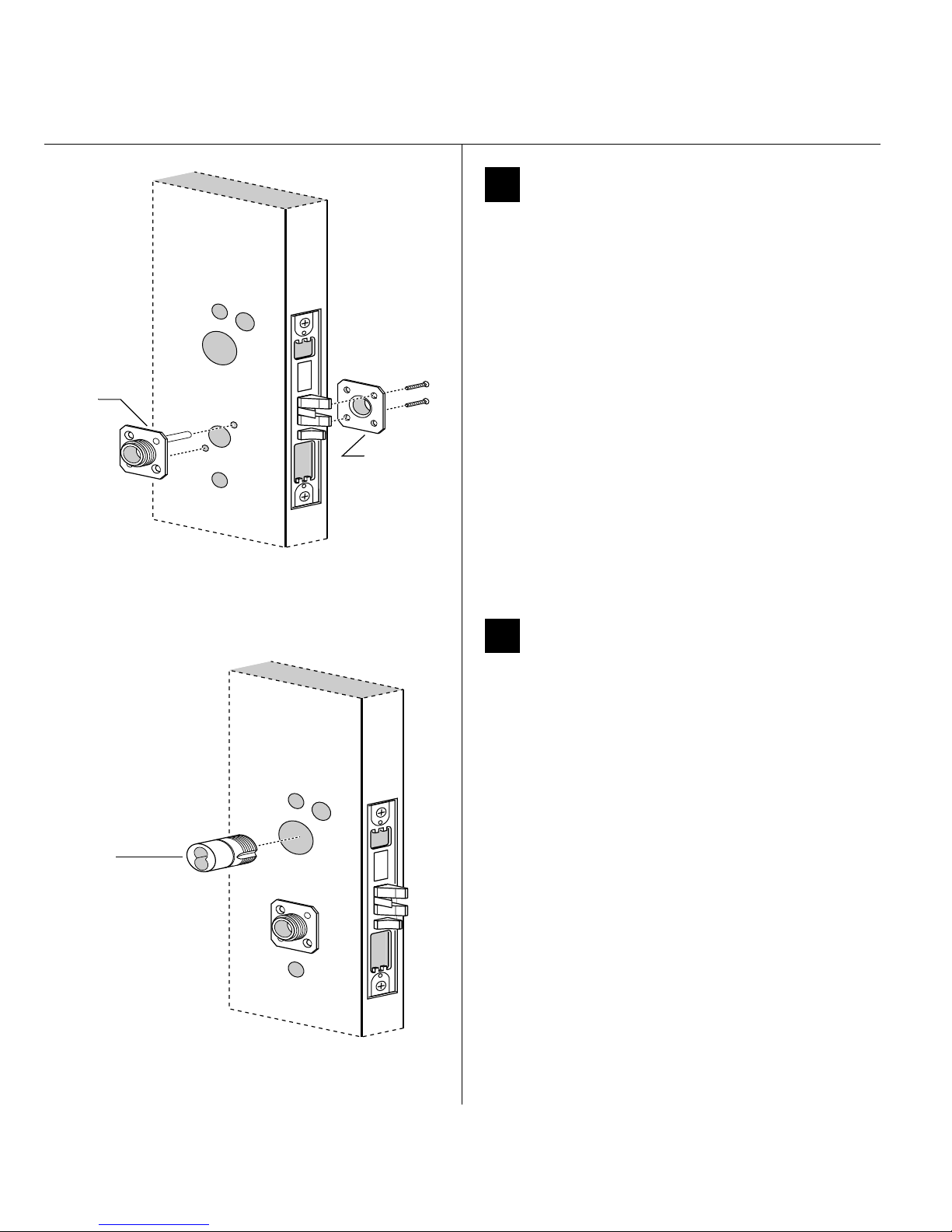
Installation Instructions for B.A.S.I.S. Mortise Locks
Outside
mounting
plate
Inside
mounting
plate
Outside of door
Installing the lock
7 Install mounting plates
1 Insert the outside mounting plate through the door
and mortise case.
2 Position the inside mounting plate opposite the
outside mounting plate and screw them securely in
place.
Caution: Do not overtighten the mounting plate
screws. Overtightening may compress the mortise
cavity and bind the locking mechanism.
Figure 7 Installing the mounting plates
Concealed
cylinder
Outside of door
8 Install cylinder (EV and FV only)
Use a cylinder wrench (ED211) to thread the concealed
cylinder into the mortise case so that the groove
around the cylinder head is even with the door surface.
Note: Do not tighten the cylinder set screw until you
perform task 11 on page 8.
Caution: A malfunction can occur if the cylinder is
threaded in too far.
Figure 8 Installing the cylinder
6
BEST ACCESS SYSTEMS
Indianapolis, Indiana
Page 29
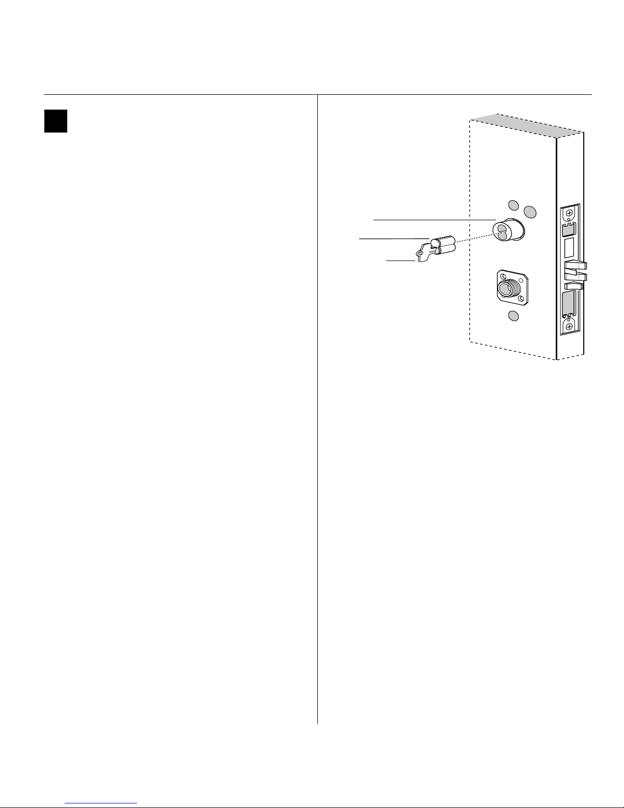
Installing the lock
9 Install core (EV and FV only)
1 Insert the control key into the core and rotate the key
15 degrees to the right.
2 With the control key in the core, insert the core into
the cylinder.
3 Rotate the control key 15 degrees to the left and
withdraw the key.
Caution: The control key can be used to remove
cores and to access doors. Provide adequate
security for the control key.
Installation Instructions for B.A.S.I.S. Mortise Locks
Installation Instructions for B.A.S.I.S. Mortise Locks
Cylinder
Core
Control key
Outside of door
Figure 9 Installing the core
BEST ACCESS SYSTEMS
Indianapolis, Indiana
7
Page 30
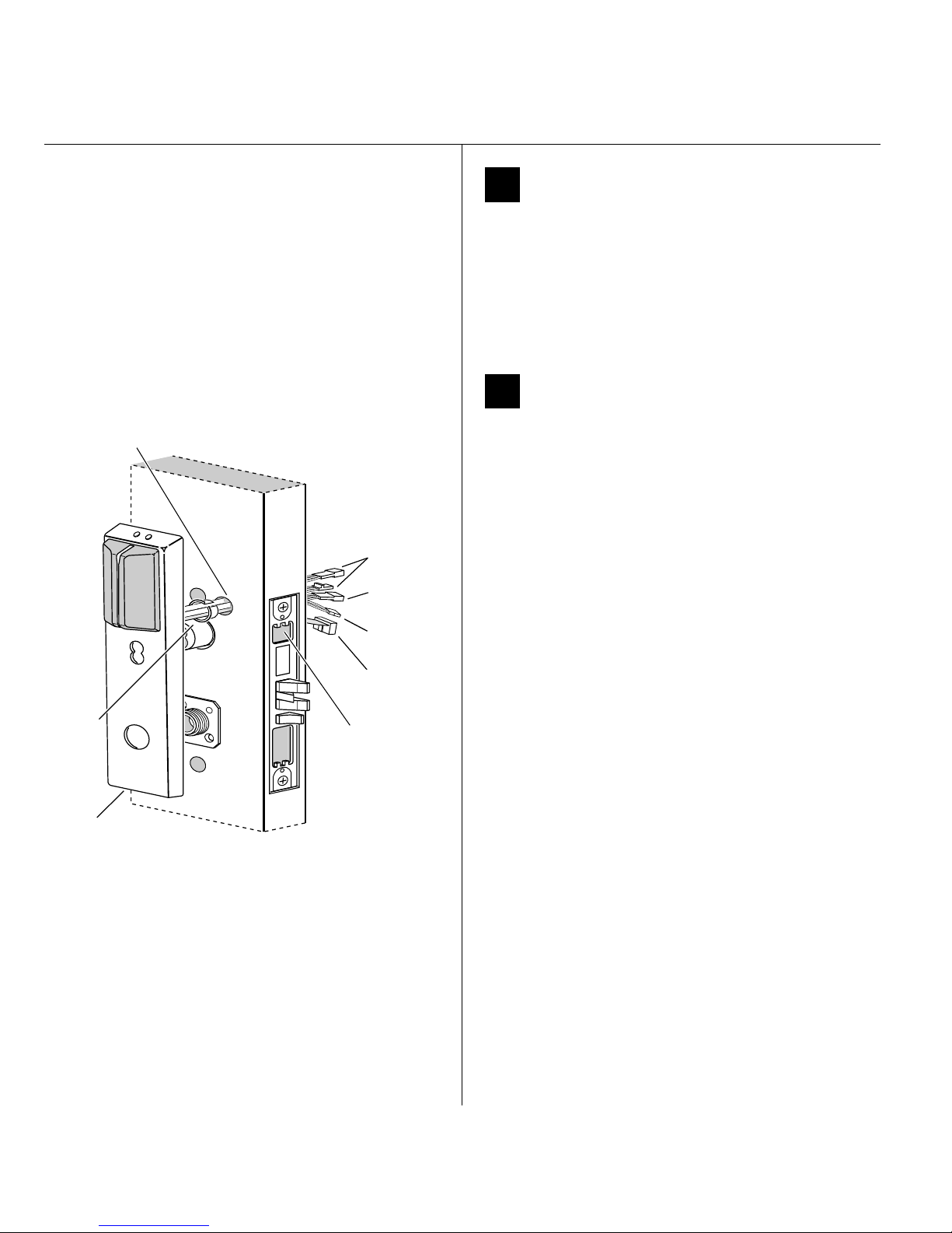
Installation Instructions for B.A.S.I.S. Mortise Locks
Installing the lock
10 Remove backup battery tab
Caution: For the lock to operate properly, you
must remove the backup battery tab.
1 Locate the backup battery tab on the inside of the
outside escutcheon.
2 Pull down on the tab and remove it from the outside
escutcheon to turn on the backup battery.
11 Route wire harnesses and position
outside escutcheon
Harness hole
Sensor
connectors
Battery
connector
Motor
connector
Upgrade
connector
Bushing
Bushing
Outside
escutcheon
Outside of door
Cylinder set
screw (inside
mortise case)
Figure 11 Feeding the wire harness connectors through
the harness hole
1 Insert the two bushings into the harness hole on each
side of the door, as shown in Figure 11 and Figure 12.
2 From the outside of the door, feed the upgrade
connector through the harness hole.
3 From the outside of the door, feed the motor
connector, battery connector, and sensor connectors
through the harness hole.
Note: NV function locks do not have a sensor harness.
Caution: When routing the connectors, make sure
the harnesses are not routed across any sharp
edges or over any surface that could damage their
sleeving or wire insulation.
4 For EV and NV function locks, perform these steps:
a Firmly press the outside escutcheon in position on
the door. The core should be flush with the outer
surface of the escutcheon.
b If necessary, adjust the cylinder depth plus or
minus one turn so that the core is flush with the
outer surface of the escutcheon.
c Secure the cylinder in the mortise case with the
cylinder set screw.
5 Rest the outside escutcheon on the door by inserting
the trim studs into the trim holes.
Note: You can temporarily install the outside lever to
hold the outside escutcheon in place. See task 15 on
page 11.
8
BEST ACCESS SYSTEMS
Indianapolis, Indiana
Page 31
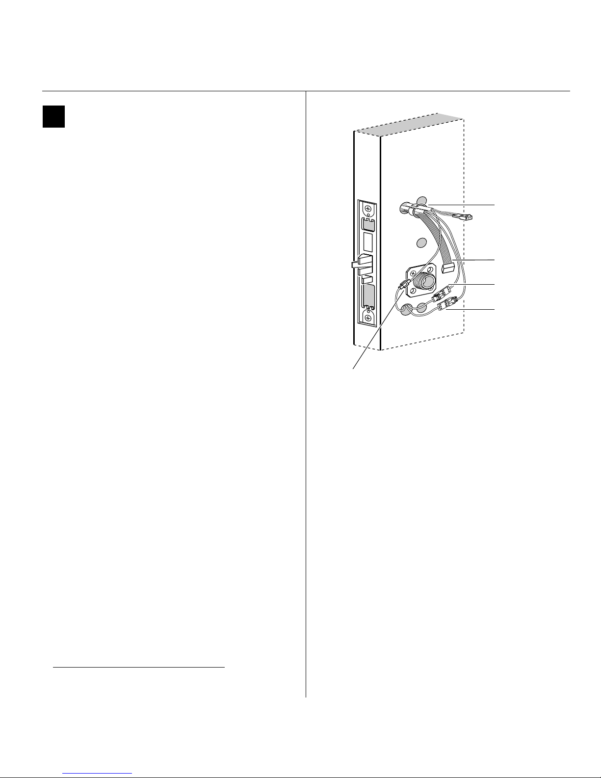
Installing the lock
12 Make motor and sensor connections
From the inside of the door, make the motor
connection, the key override sensor connection (EV
and FV functions)
connection (FV and LV functions).
Note 1: It is physically possible to connect the key
override sensor connector from the mortise case to the
battery connector from the wire harness. To avoid this
mistake, connect only the connectors with matching wire
colors.
Note 2: The upgrade cable is used for reprogramming
the lock’s firmware without removing the lock from the
door. This cable does not connect to a mating lock
connector.
Caution: When making the motor connection and
sensor connections, make sure:
■ there are no loose wire connections where the
wires are inserted into the connectors
■ the connectors are firmly mated.
†
, and the deadbolt sensor
Installation Instructions for B.A.S.I.S. Mortise Locks
Installation Instructions for B.A.S.I.S. Mortise Locks
Bushing
Upgrade cable
Deadbolt sensor
connection
Key override
sensor connection
Motor
connection
Inside of door
Wire connection Colors
Motor Yellow
Gray
Key override sensor Gray 2 3
Deadbolt sensor Blue 2 3
† Key override sensing is optional for 35HG and
standard for 35HBV.
No. of
wires
No. of
pins
22
Figure 12 Making the motor connection and
sensor connections
BEST ACCESS SYSTEMS
Indianapolis, Indiana
9
Page 32
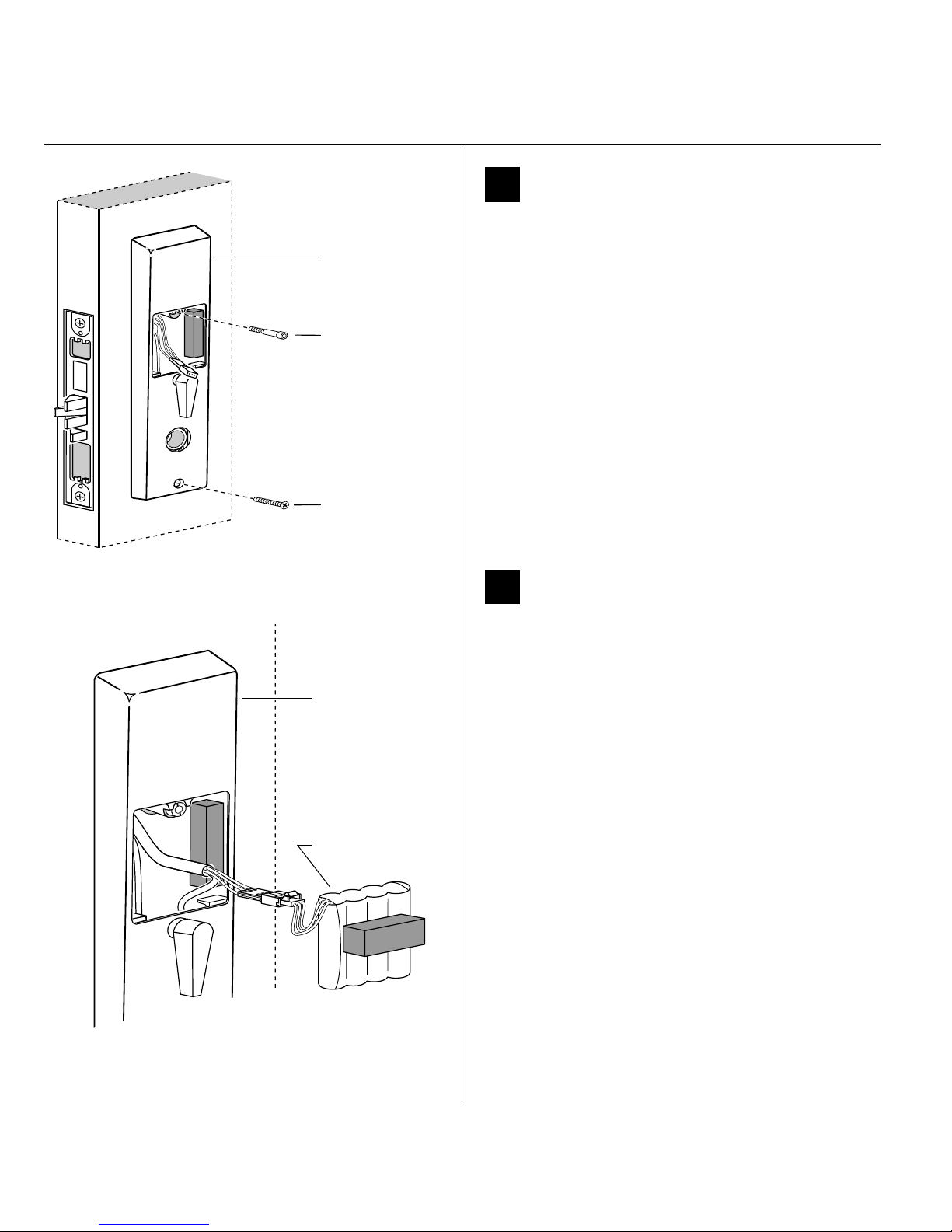
Installation Instructions for B.A.S.I.S. Mortise Locks
Inside escutcheon
Combination
mounting screw
Standard
mounting screw
Installing the lock
13 Secure escutcheons
1 Position the inside and outside escutcheons on the
door.
2 Making sure that the escutcheons do not pinch
the wires, secure the escutcheons to the door. Do not
tighten the screws completely. Use the combination
mounting screw in the upper trim hole and the
standard mounting screw in the lower trim hole.
Inside of door
Figure 13 Securing the escutcheons
Inside of door
Inside escutcheon
Battery pack
14 Install battery pack
1 Connect the battery pack to the battery connector on
the wire harness inside the battery compartment.
Wire
connection
Battery Red w/white stripe
Color
White
Black w/white stripe
Caution 1: When routing the battery wires, make
sure the wires are not routed across any sharp
edges or over any surface that could damage their
sleeving or wire insulation.
Caution 2: When connecting the battery pack,
make sure:
■ there are no loose wire connections where the
wires are inserted into the connectors
■ the connectors are firmly mated.
2 Place the battery pack inside the battery compartment
so that the foam will face the battery compartment
door.
No. of
wires
No. of
pins
33
Figure 14 Connecting the battery pack
10
BEST ACCESS SYSTEMS
Indianapolis, Indiana
Page 33
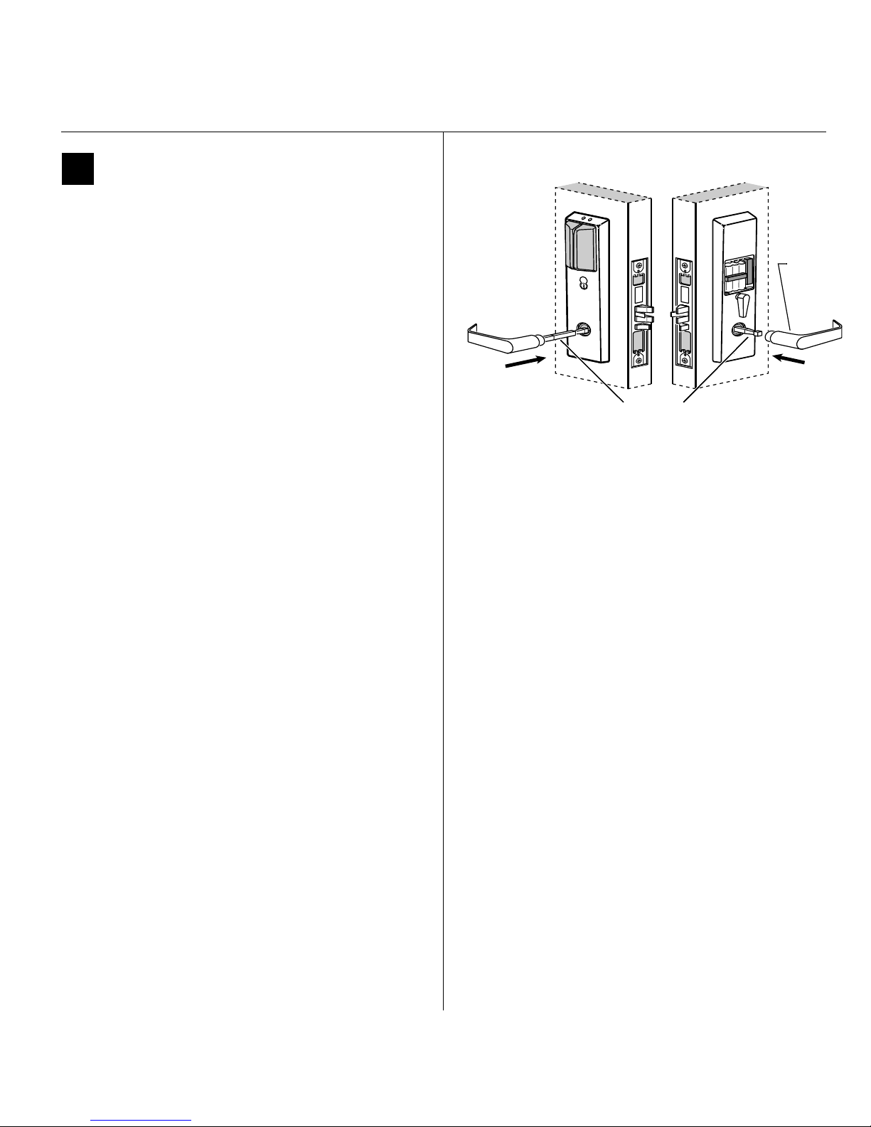
Completing the installation
15 Install inside and outside levers
1 Unscrew the inside spindle one full turn to allow the
spindles to turn freely.
2 With the handle pointing toward the door hinges,
insert the outside lever and spindles assembly into the
lock from the outside of the door.
3 Slide the inside lever onto the inside spindle and
secure it with the set screw.
4 Making sure that the core is positioned properly in the
outside escutcheon (EV and FV only) and the
escutcheons are aligned properly on the door, tighten
the escutcheon mounting screws.
Note: If a core is not available, you can use the cylinder
wrench (ED211) to help you align the core opening in the
escutcheon.
5 Turn the levers to check that they operate smoothly.
Installation Instructions for B.A.S.I.S. Mortise Locks
Installation Instructions for B.A.S.I.S. Mortise Locks
Outside of door Inside of door
Outside of door
Spindles
Spindles
Figure 15 Installing the levers
Location
of set
screw
BEST ACCESS SYSTEMS
Indianapolis, Indiana
11
Page 34
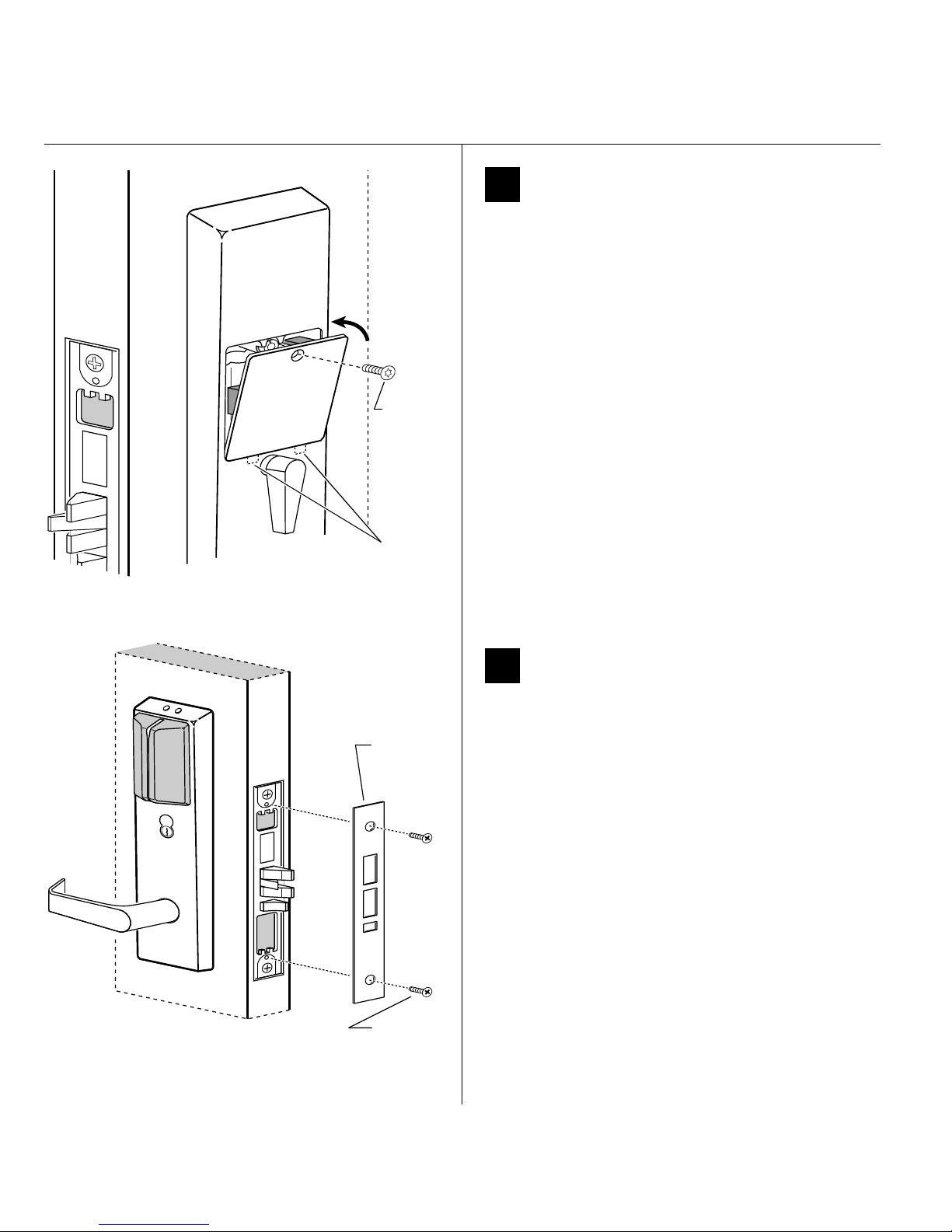
Installation Instructions for B.A.S.I.S. Mortise Locks
Security
screw
Tabs
Completing the installation
16 Install battery compartment door
1 Making sure that the battery compartment door
does not pinch any wires, insert the tabs of the
battery compartment door into its mating slots and
swing the door closed.
2 Use a T15 TORX bit driver to secure the battery
compartment door with the security screw. Tighten
firmly.
Figure 16 Installing the battery compartment door
Mortise
case
faceplate
Outside of door
Figure 17 Installing the mortise case faceplate
Faceplate
mounting
screws
17 Install mortise case faceplate
1 Secure the mortise case faceplate to the mortise case
with the faceplate mounting screws.
2 Check the lock for proper operation.
12
BEST ACCESS SYSTEMS
Indianapolis, Indiana
Page 35
Completing the installation
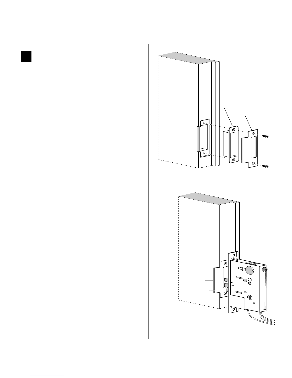
18 Install strike box and strike plate
1 Insert the strike box into the mortise in the door jamb.
Place the strike plate over the strike box and secure the
strike with the screws provided.
2 Check the position of the auxiliary bolt against the
strike plate.
Caution: The auxiliary bolt must make contact
with the strike plate. The auxiliary bolt deadlocks
the latchbolt and prevents someone from forcing
the latch open when the door is closed. If the
incorrect strike is installed, a lock-in can occur.
Note: The recommended gap between the door and
jamb is 1/8″.
Installation Instructions for B.A.S.I.S. Mortise Locks
Installation Instructions for B.A.S.I.S. Mortise Locks
Strike box
Strike plate
Door jamb
Figure 18a Installing the strike box and strike plate
Strike plate
Auxiliary bolt
Figure 18b Positioning the strike
BEST ACCESS SYSTEMS
Indianapolis, Indiana
13
Page 36
Installation Instructions for B.A.S.I.S. Mortise Locks
Completing the installation
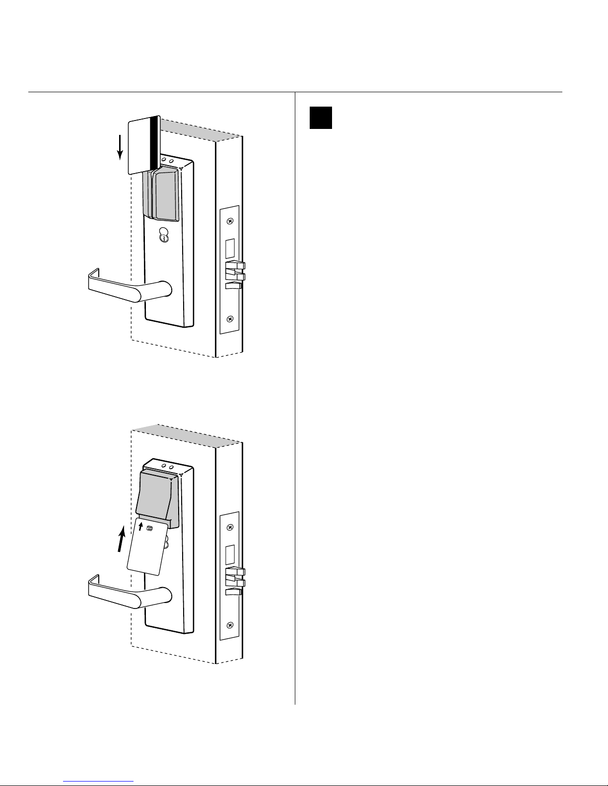
19 Test lock
To test the lock for proper operation, use the temporary
operator card that came with the lock. This card is for
temporary use only. After permanent cards have been
programmed for the lock, the temporary card should be
deleted.
For locks with magnetic stripe card readers
1 With the magnetic stripe facing towards the right,
swipe the temporary operator card, as shown in
Figure 19a.
The green light flashes and the locking mechanism
unlocks.
2 Turn the lever and open the door.
Figure 19a Using the temporary operator card with a
magnetic stripe card reader
Operator
Temporary
For locks with smart card readers
1 With the writing facing towards you, insert and
remove the temporary operator card, as shown in
Figure 19b.
The green light flashes and the locking mechanism
unlocks.
2 Turn the lever and open the door.
Figure 19b Using the temporary operator card with a
smart card reader
14
BEST ACCESS SYSTEMS
Indianapolis, Indiana
Page 37
Completing the installation
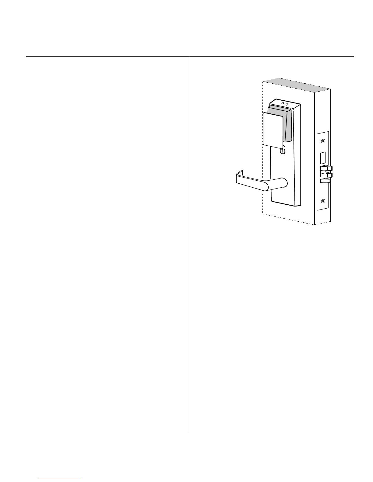
For locks with proximity card readers
1 Hold the temporary operator card within an inch of the
lock’s card reader, as shown in Figure 19c.
The green light flashes and the locking mechanism
unlocks.
2 Turn the lever and open the door.
If the mechanism doesn’t unlock, refer to the
following table.
LEDs Sounder Access You should
Installation Instructions for B.A.S.I.S. Mortise Locks
Installation Instructions for B.A.S.I.S. Mortise Locks
Temporary
Operator
—3 short
tones
Red
flashes
Green
flashes
— — Denied Check the battery
3 short
tones
— Denied Check the motor
Denied Use the card at a moderate
speed.
Denied Use the temporary
operator card provided
with the lock.
connection.
connection.
For all EV and FV function locks
Insert and turn the key to unlatch the door.
For all FV and LV function locks
From the inside of the door, turn the turn knob and
make sure that the deadbolt operates properly.
Figure 19c Using the temporary operator card with a
proximity card reader
BEST ACCESS SYSTEMS
Indianapolis, Indiana
15
Page 38

Installation Instructions for B.A.S.I.S. Mortise Locks
16
BEST ACCESS SYSTEMS
Indianapolis, Indiana
© 2000 Best Lock Corporation dba Best Access Systems.
T63302/Rev B 1817313 ER-7991-12 June 2001
 Loading...