


75KC
Installation Instructions
for 72KC–75KC Cylindrical Locks
For factory prepared doors only
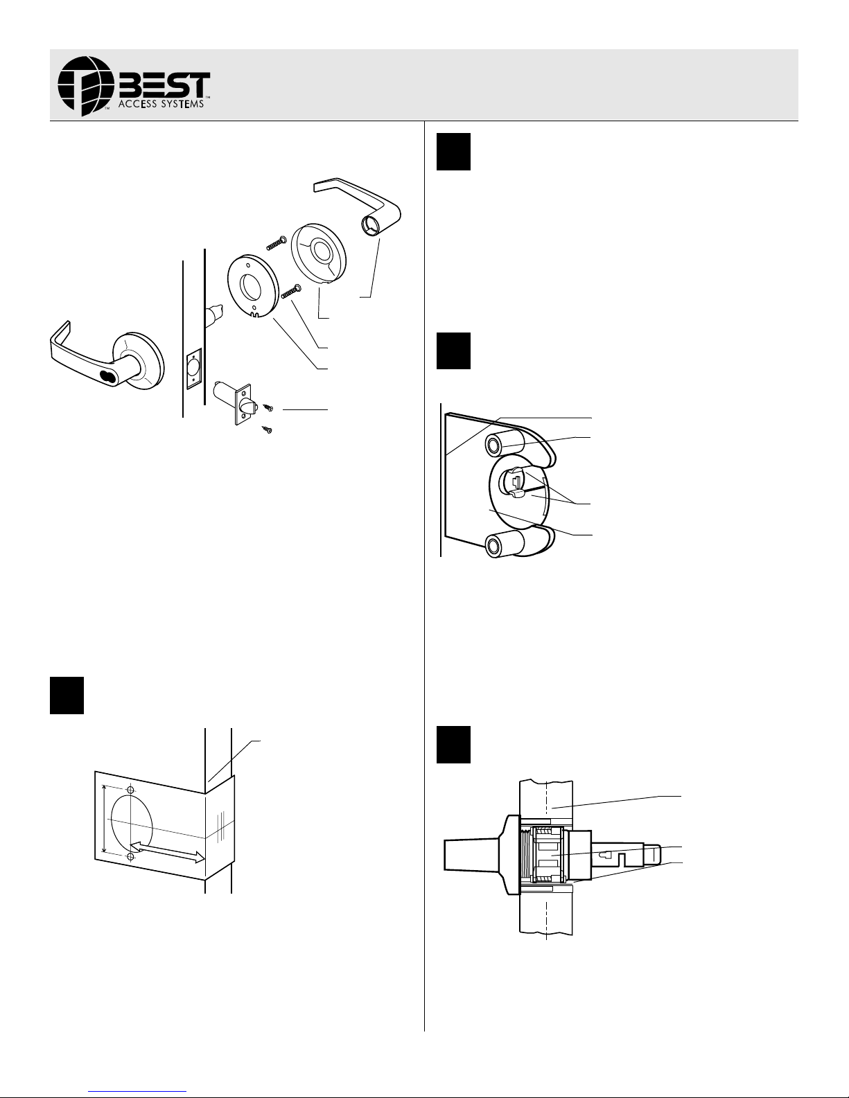
Lever
Inside rose
2
Bore two holes and install latch
1 Bore a 2 1/8" diameter hole from both sides of the door, to the center
of the door.
2 Drill a 1" diameter hole from the edge of the door that intersects the
2
1/8" hole.
3 Mortise the door edge for the latch face.
4 Install the latch through the 1” diameter hole. For drive-in latches,
use a rubber mallet. Latch tabs should project into the 2
diameter hole. See figure 3 in task 3.
5 Check the door swing.
1/8"
Through-bolts
Inside liner
Outside
Figure 1 — Overview of installing the lock
Caution: If you use hollow metal doors, determine whether the
doors are reinforced enough to support the lock. If door rein
forcement is not adequate, consult the door manufacturer for
information on proper reinforcement.
Simplified instructions
1 Install the latch so that the bevel on the latchbolt faces the strike.
2 Adjust the outside rose assembly so that the chassis is centered in
the door. Install the chassis from the outside of the door.
3 Install the inside liner, through-bolts, rose, lever and strike.
For field door preparation and detailed installation instructions, see the
following tasks.
1
Position template
High edge of door bevel
Latch
-
3
Install boring jig and drill two
5/16
”
diameter holes
Door edge
5/16” diameter
Latch tabs
Boring jig
Figure 3 — Installing the boring jig onto the door
1 Install the boring jig onto the door and engage with the latch tabs.
Make sure the front edge of the jig is parallel with the door edge. See
Figure 3.
2 Drill two 5/16" diameter holes halfway into the door.
3 Turn the boring jig over and repeat steps one and two from the
opposite side of the door.
Note: Replace the boring jig after ten door preparations.
4
Adjust lock to door thickness
TEMPLATE
Figure 2 — Placing the template onto the door
1 Fold the template and place it in position on the high edge of the
door bevel. See
2 Mark the drill points.
Note: The suggested height from the floor to centerline of the lock is
40 5/16". If steel frames are used, the latch centerline must be in line
with the center of the strike preparation.
T80622/Rev B 1827069 ER-7991-19 Sept 2004
Figure 2.
Figure 4 — Adjusting the lock to match the door thickness
1 Temporarily remove the latch.
BEST ACCESS SYSTEMS
Indianapolis, Indiana
Door center
Retractor
Pull pin to rotate rose
—Continued
 Loading...