

Page 1
WTT32I Series
In USA - BEST® Hartford, Wisconsin
REGISTER YOUR PRODUCT ONLINE AT : www.BestRangeHoods.com/register
For additional Information visit www.BestRangeHoods.com
HB0103
Page 2

- 2 -
READ AND SAVE THESE INSTRUCTIONS
WARNING
TO REDUCE THE RISK OF FIRE, ELECTRIC SHOCK, OR INJURY TO PERSON(S)
OBSERVE THE FOLLOWING:
1. Use this unit only in the manner intended by the manufacturer. If you have
questions, contact the manufacturer at the address or telephone number listed
in the warranty.
2. Before servicing or cleaning unit, switch power off at service panel and lock
service disconnecting means to prevent power from being switch on accidentally.
When the service disconnecting means cannot be locked, securely fasten a
prominent warning device, such as a tag, to the service panel.
3. Installation work and electrical wiring must be done by qualified personnel
in accordance with all applicable codes and standards, including fire-rated
construction codes and standards.
4. Sufficient air is needed for proper combustion and exhausting of gases
through the flue (chimney) of fuel burning equipment to prevent backdrafting.
Follow the heating equipment manufacturer’s guidelines and safety
standards such as those published by the National Fire Protection
Association (NFPA), the American Society for Heating, Refrigeration
and Air Conditioning Engineers (ASHRAE) and the local code authorities.
5. This product may have sharp edges. Be careful to avoid cuts and abrasions
during installation and cleaning.
6. When cutting or drilling into wall or ceiling, do not damage electrical wiring and
other hidden utilities.
7. Ducted fans must always be vented to the outdoors.
8. To reduce the risk of fire, use only steel ductwork.
9. Do not use this unit with any other solid-state speed control device.
10. Do not operate any fan with a damaged cord or plug. Discard fan or return to
an authorized service facility for examination and/or repair.
11. GROUNDING INSTRUCTION: The appliance must be grounded. In the event
of an electrical short circuit, grounding reduces the risk of electric shock by
providing an escape wire for the electric current. The appliance is equipped with
a cord having a grounding wire with a grounding plug. The plug must be plugged
into an outlet that is properly installed and grounded. WARNING: Improper
grounding can result in a risk of electric shock. Consult a qualified electrician if
the grounding instructions are not completely understood, or if doubt exists as
to whether the appliance is properly grounded. Do not use an extension cord. If
the power supply cord is too short, have a qualified electrician install an outlet
near the appliance.
!
INTENDED FOR DOMESTIC COOKING ONLY
!
Page 3

- 3 -
!
CAUTION
1. For indoor use only.
2. For general ventilating use only. Do not use to exhaust hazardous or explosive
materials and vapors.
3. To avoid motor bearing damage and noisy and/or unbalanced impeller, keep
drywall spray, construction dust, etc. off power unit.
4. Your hood motor has a thermal overload which will automatically shut off the
motor if it becomes overheated. The motor will restart when it will cool down. If
the motor continues to shut off and restart, have the hood serviced.
5. The bottom of the hood MUST NOT BE LESS than 24” and at a maximum of
30” above cooktop for best capture of cooking impurities.
6. Two installers are recommended because of the size of this hood.
7. To reduce risk of fire and to properly exhaust air, be sure to duct air outside. Do
not exhaust air into spaces within walls or ceilings or into attics, crawl spaces,
or garages.
8. Be careful when installing the decorative flue and hood, they may have sharp
edges.
9. Please read specification label on product for further information and
requirements.
TO REDUCE THE RISK OF A RANGE TOP GREASE FIRE:
a) Never leave surface units unattended at high settings. Boilovers cause smoking
and greasy spillovers that may ignite. Heat oils slowly on low or medium settings.
b) Always turn hood ON when cooking at high heat or when cooking flaming foods
(i.e. Crêpes Suzette, Cherries Jubilee, Peppercorn Beef Flambé).
c) Clean ventilating fans frequently. Grease should not be allowed to accumulate
on fan or filters.
d) Use proper pan size. Always use cookware appropriate for the size of the
surface element.
TO REDUCE THE RISK OF INJURY TO PERSON(S) IN THE EVENT OF A RANGE
TOP GREASE FIRE, OBSERVE THE FOLLOWING*:
1. SMOTHER FLAMES with a close-fitting lid, cookie sheet, or metal tray, then turn
off the burner. BE CAREFUL TO PREVENT BURNS. IF THE FLAMES DO NOT
GO OUT IMMEDIATELY, EVACUATE AND CALL THE FIRE DEPARTMENT.
2. NEVER PICK UP A FLAMING PAN – You may be burned.
3. DO NOT USE WATER, including wet dishcloths or towels – This could cause
a violent steam explosion.
4. Use an extinguisher ONLY if:
A. You know you have a Class ABC extinguisher and you know how to
operate it.
B. The fire is small and contained in the area where it started.
C. The fire department has been called.
D. You can fight the fire with your back to an exit.
* Based on “Kitchen Fire Safety Tips” published by NFPA.
Page 4
- 4 -
OPERATION
Always turn your hood on before you begin cooking to establish an air flow in the
kitchen. Let the blower run for a few minutes to clear the air after you turn off the
range.
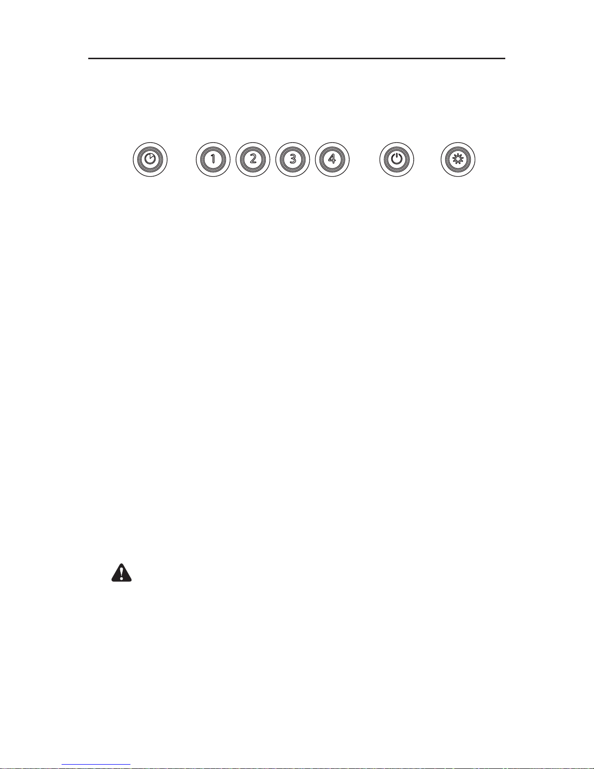
The hood is operated using the push buttons on the front panel.
A. DELAY SWITCH
When a blower speed is selected, press this switch to activate the delay func-
tion. The delay button will illuminate to indicate this function is activated. The
blower will continue to operate for 5 minutes and will stop automatically. To
cancel the delay function, press the delay switch once again.
B. START / STOP / SPEED SELECTION SWITCHES
Press the switch corresponding to the desired blower speed (from 1 for low
speed to 4 for high speed). The chosen switch will light. To turn off the blower,
press once more on the corresponding blower speed switch; the switch light
will shut off.
C. MASTER OFF / FILTER MAINTENANCE / HEAT SENTRY™
(TRIPLE FUNCTION SWITCH)
To turn off the blower and the light simultaneously, press this switch once. After
25 hours of operation, this switch will light to indicate the filters and the blower
wheel(s) need to be cleaned in order to maintain efficient operation of the unit.
The switch light will stay on until the function is reset by pressing this switch for
3 seconds. The light indicator is used for the Heat Sentry function as well.
HEAT SENTRY: When an excessively high temperature is detected, the Heat
Sentry takes control over the blower and sets it on speed 3. The triple-function
switch will flash.The blower will remain on until the heat condition is back to
normal. It will then return to the speed previously selected.
WARNING: The Heat Sentry can start the blower even if the hood is
turned off. When this situation occurs, it is impossible to turn the blower
off using the push buttons. If you must stop the blower, do it from the
main electrical panel.
D. LIGHT SWITCH
This switch allows three different lighting levels according to your needs. Press
once for nightlight, twice for normal or three times to obtain full intensity. To
shut off the lights without turning off the blower, press once more.
A B C D
Page 5
- 5 -
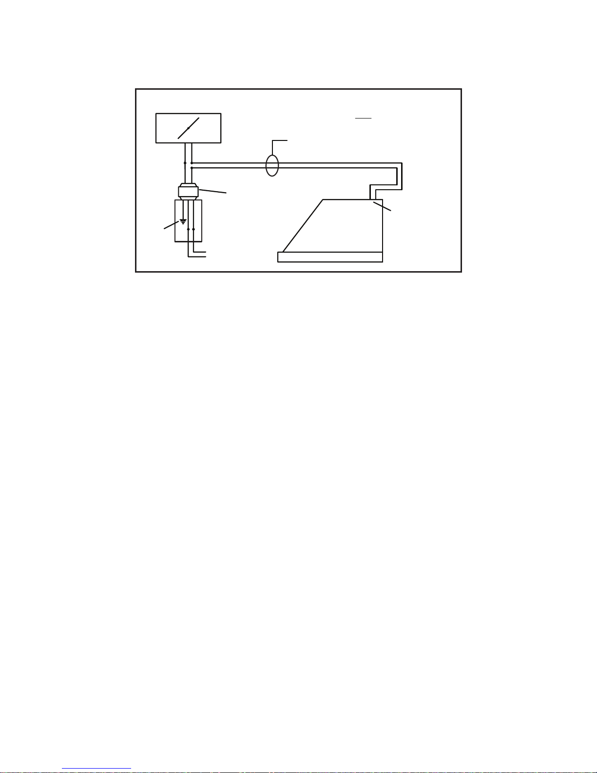
MAKE-UP AIR DAMPER
HOOD
24V
TRANSFORMER
(INCLUDED)
GRD
DRY CONTACT
TERMINAL
BUSHING
FOR LOW
VOLTAGE
CONNECTION
MAKE UP DAMPER CONNECTION
(switched low voltage)
20 GAUGE BELL WIRE FOR LOW
VOLTAGE CONNECTION ON
TOP OF HOOD
120 VAC
60 HZ
MAKE-UP AIR DAMPER
The hood is compatible with Broan Make-Up Air Damper Model MD6T or Model MD8T
(optional). Purchase separately.
Make the connection to the Make-Up Air Damper with low voltage wiring, as shown. See
Make-Up Air Damper instructions for additional information.
Page 6
- 6 -
CLEANING & MAINTENANCE
For performance, appearance, and health reasons, clean filter, fan and grease-laden
surfaces regularly. Use only a clean cloth and mild detergent solution on stainless and
painted surfaces.
Clean all-metal filters in the dishwasher using a non-phosphate detergent. Discoloration of
the filter may occur if using phosphate detergents, or as a result of local water conditions but this will not affect filter performance. This discoloration is not covered by the warranty.
Clean the non-duct recirculating filter surfaces frequently with a damp cloth and a mild
detergent. DO NOT immerse filters in water or put in dishwasher. Change the nonduct recirculating filters every 6 months. For replacement non-duct recirculating filters
- purchase S97018968 or Model AFCWTT32 (for 30” wide hood) or S97019039 or Model
AFCWTT326 (for 36” and 42” wide hoods).
The motor is permanently lubricated and never needs oiling. If the motor bearings
make excessive or unusual noise, replace the blower assembly with an exact service
replacement.
LIGHT BULBS
WARNING:
Bulbs may be hot.
Always allow bulbs
to cool down before
removing them.
Use (2) Halogen Bulbs
(included with hood) 120 V, 50 W, shielded
halogen bulbs - MR16
with GU10 base. (3
bulbs for 42” & 48”
hoods.)
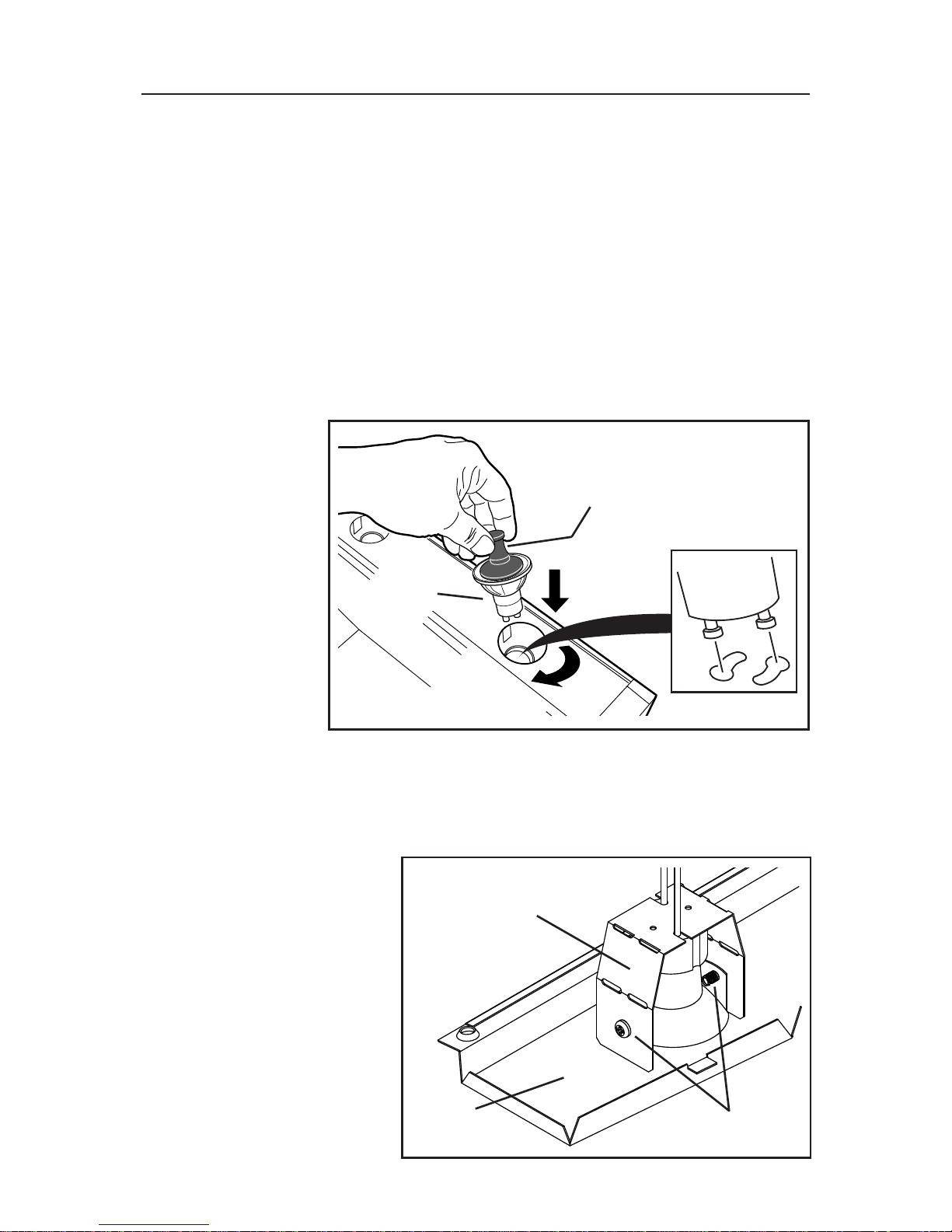
NOTE:
Suction Cup Tool
(included with hood) can be used to install and remove light bulbs. Align pins on bulb
with large diameter opening on socket, then push bulb in towards hood and rotate
clockwise until firmly seated. The position of the bulb socket (depth) is adjustable and
may require adjustment when: a) certain brands of bulbs are difficult to install. b) the
bulb protrudes too far below the light panel.
LAMP SOCKET
BRACKET
SCREWS
LIGHT
PANEL
To change the depth of bulb
sockets:
- Remove screws on light
panel – set screws aside
- Remove Light Panel.
- Loosen 2 Screws holding
Lamp Socket Bracket to Light
Panel.
- Adjust socket/bracket to
desired depth.
- Re-tighten screws securely.
- Re-attach light panel with
screws that were previously
set aside.
(1)
PUSH IN
(2)
ROTATE
CLOCKWISE
SUCTION
CUP TOOL
HALOGEN
BULB
Page 7
- 7 -
INSTALL THE DUCTWORK
(Ducted Hoods Only)
1. Decide where the ductwork will run between the hood and the outside.
2. A straight, short duct run will allow the hood to perform most efficiently.
3. Long duct runs, elbows and transitions will reduce the performance of the
hood. Use as few of them as possible. Larger ducting may be required for best
performance with longer duct runs.
4. Install wall cap or roof cap. Connect round metal ductwork to cap and work back
towards the hood location. Use duct tape to seal the joints between ductwork
sections.
MEASURE THE INSTALLATION
The minimum hood distance above cooktop MUST NOT BE LESS than 24”.
A maximum of 30” above cooktop is highly recommended for best capture of
cooking impurities.
Distances over 30” are at the installer and users discretion; providing that the
ceiling height permits.
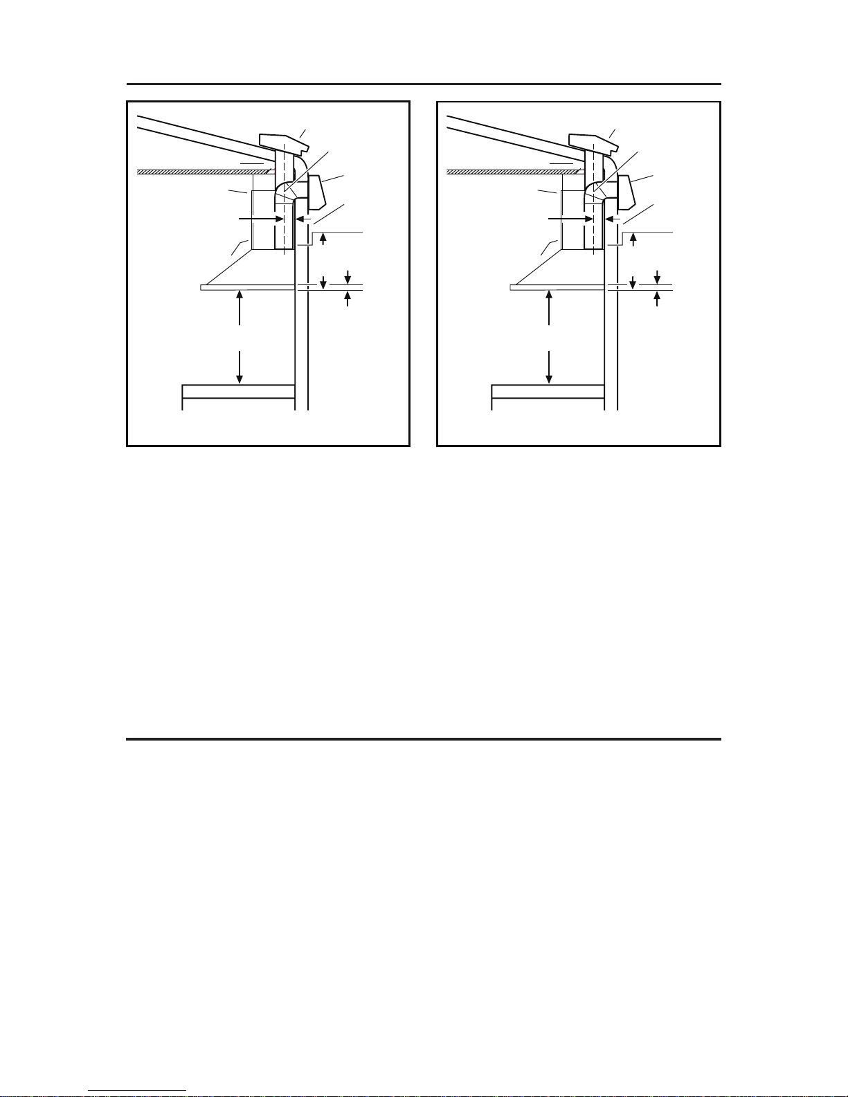
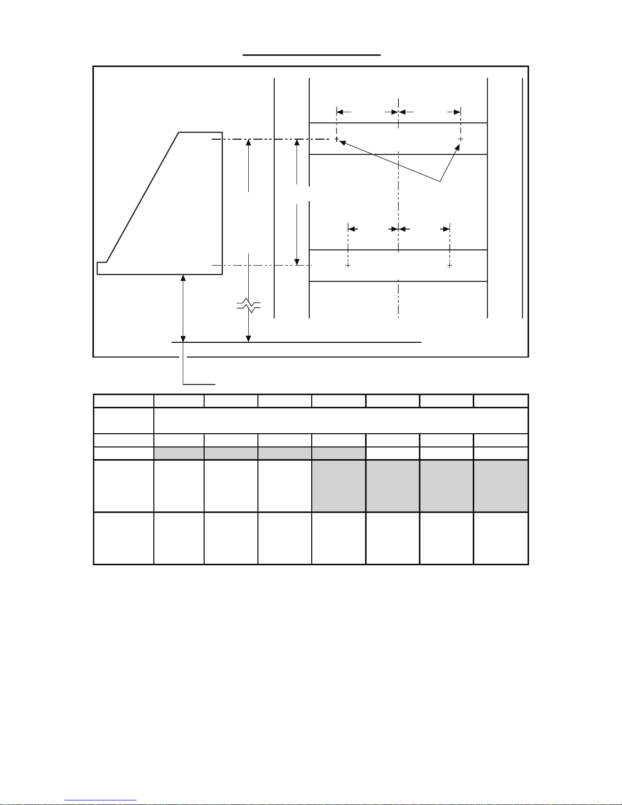
HOOD
13 1/8” TO CENTER
OF
UPPER MOUNTING
HOLES
ROUND
ELBOW
HOOD
MOUNTING
BRACKET
24” TO 30” ABOVE
COOKING
SURFACE
DECORATIVE
FLUE
8”
ROUND DUCT
ROOF
CAP
WALL CAP
1 3/8” TO CENTER
OF
LOWER HOOD
CHASSIS
HOLES
4 3/8”
FROM WALL TO
CENTER
LINE OF DUCT
DECORATIVE FLUE
HOOD
12 1/8” TO CENTER
OF
UPPER MOUNTING
HOLES
ROUND
ELBOW
HOOD
MOUNTING
BRACKET
24” TO 30” ABOVE
COOKING
SURFACE
DECORATIVE
FLUE
10” ROUND DUCT
ROOF
CAP
WALL CAP
1 3/8” TO CENTER
OF
LOWER HOOD
CHASSIS
HOLES
6 9/16”
FROM WALL TO
CENTER
LINE OF DUCT
DECORATIVE FLUE
For 30”, 36”, & 42” Hoods For 48” Hoods
Page 8
- 8 -
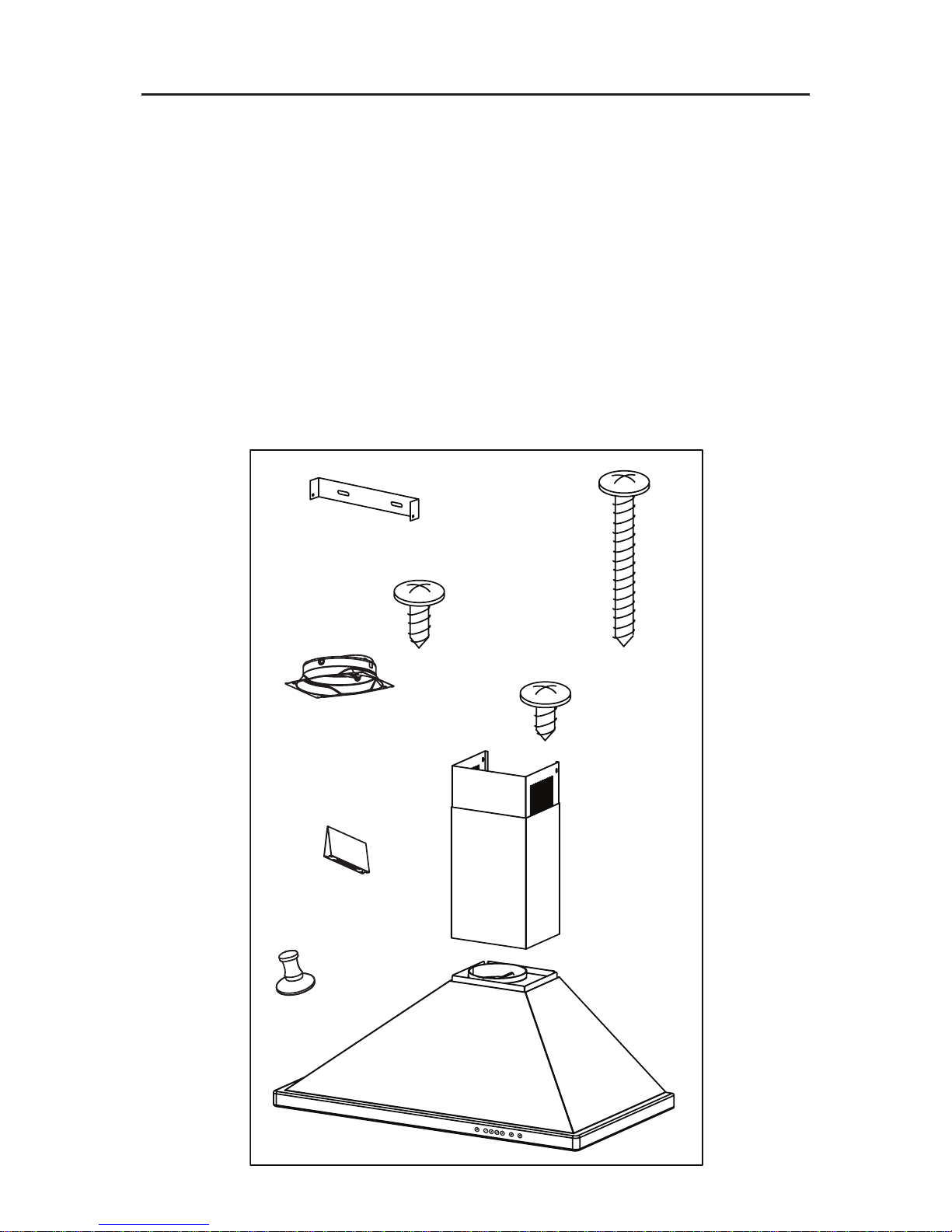
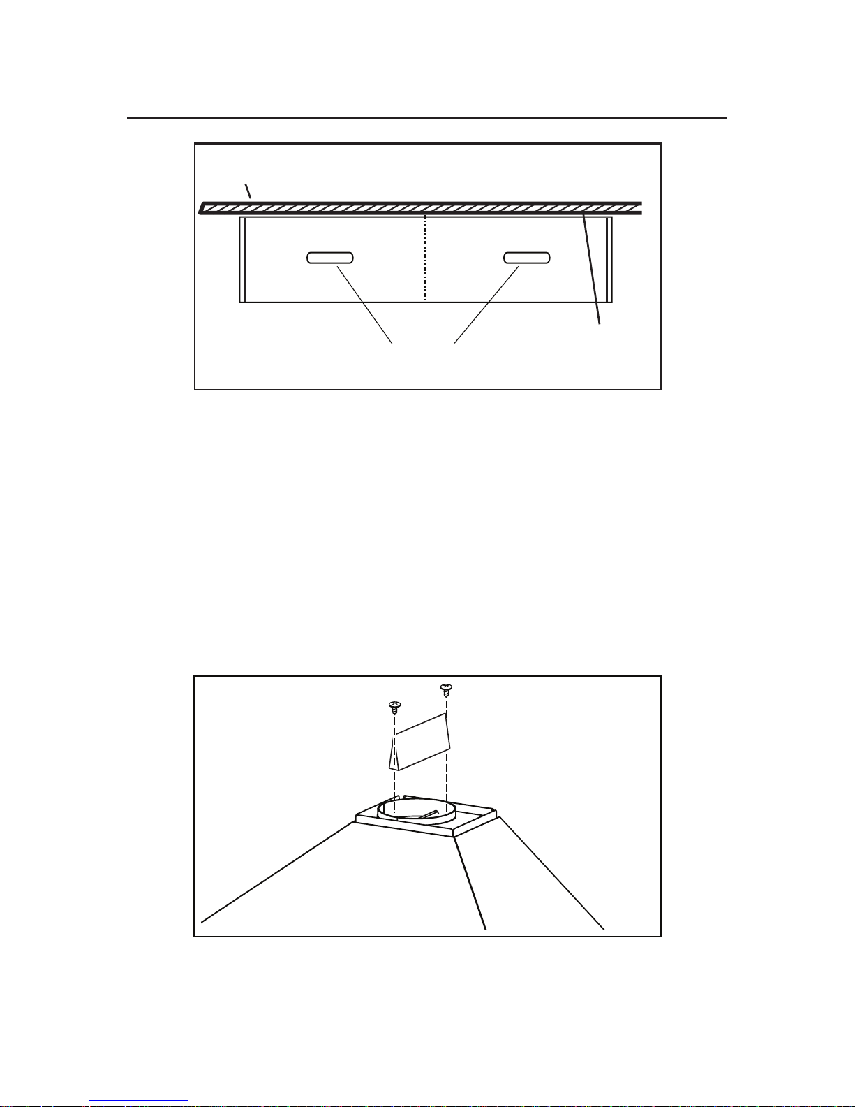
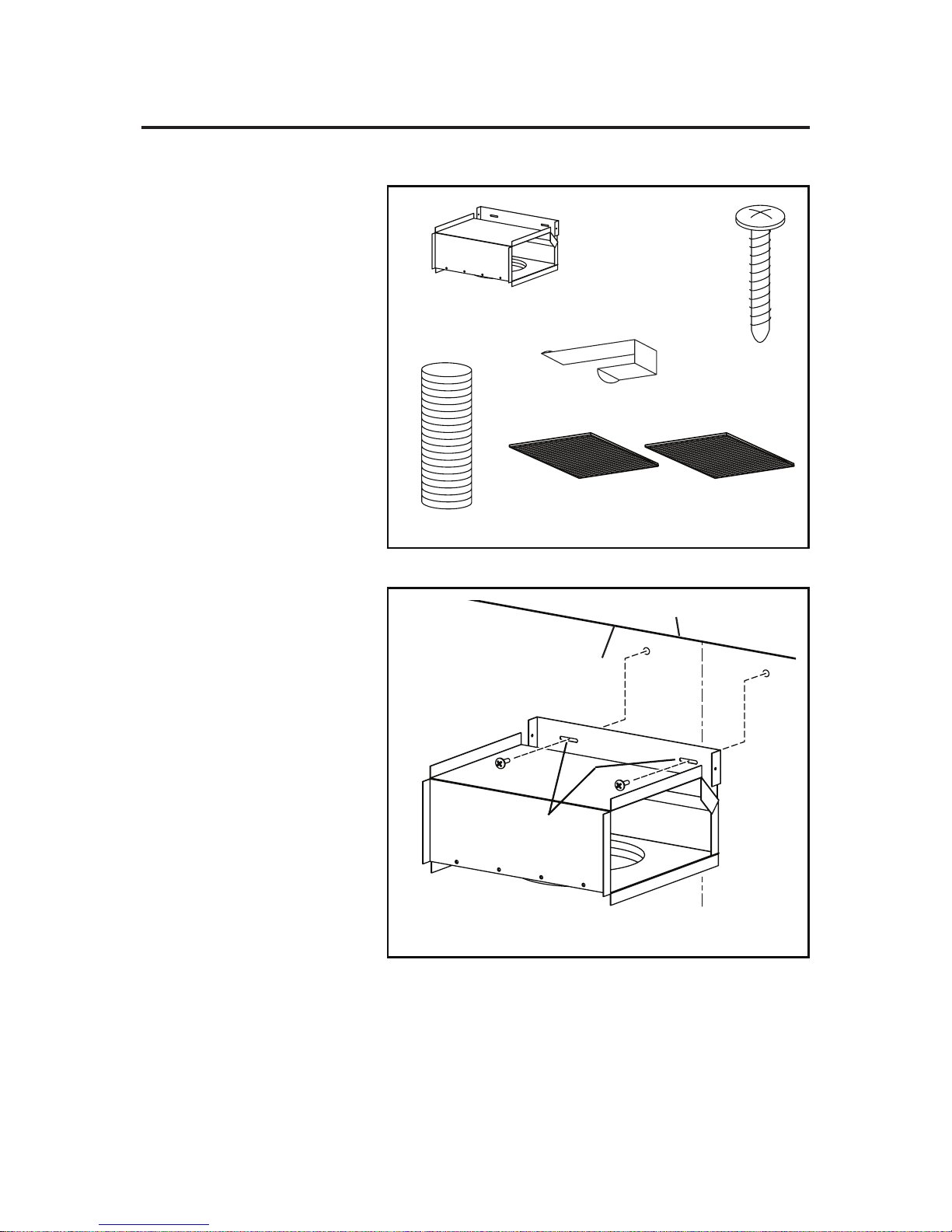
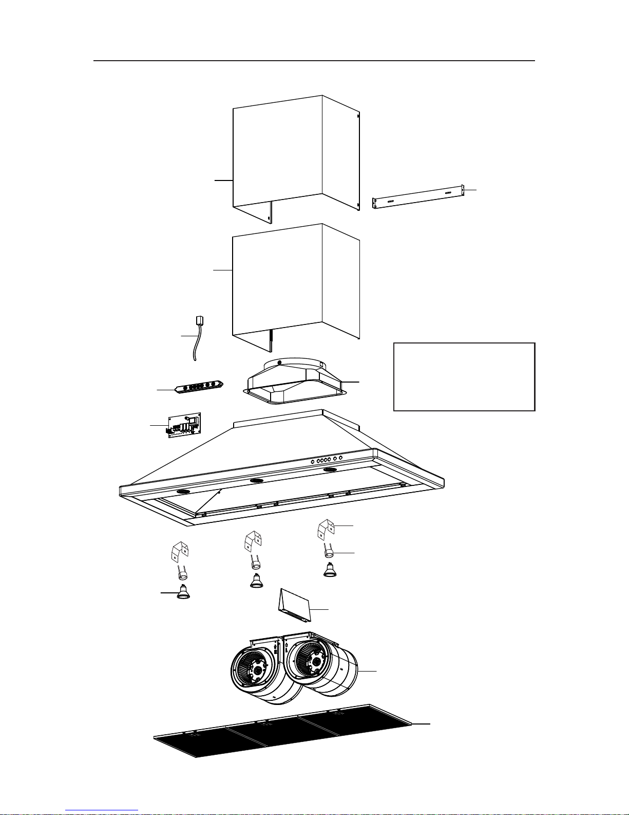
PREPARE THE HOOD
Unpack hood and check contents. You should receive:
1 - Hood Assembly
1 - Decorative Flue Assembly (consisting of upper and lower flue)
1 - Upper Flue Mounting Bracket
2 - Aluminum Grease Filters (installed on hood) (3 - on 48” model)
2 - 50W MR16 GU10 Halogen Lamps (installed on hood) (3 - on 42” & 48” model)
1 - 8” Damper / Duct Connector (for 30”, 36”, 42” models)
1 - 10” Damper / Duct Connector (for 48” model)
1 - Damper Diverter (for 48” model)
1 - Parts Bag containing:
6 - Mounting Screws (4mm x 38mm Cross Recessed Pan Head)
2 - Mounting Screws (4mm x 12mm Cross Recessed Pan Head)
4 - Mounting Screws (4mm x 8mm Cross Recessed Pan Head) (6 for 48” model)
1 - Suction Cup Tool (for bulb installation / removal)
6 MOUNTING
SCREWS
(4mm x 38mm
Cross Recessed
Pan Head)
2 MOUNTING
SCREWS
(4mm x 12mm
Cross Recessed
Pan Head)
DECORATIVE
FLUE
ASSEMBLY
UPPER
FLUE MOUNTING
BRACKET
BULB
SUCTION
CUP TOOL
HOOD
ASSEMBLY
1 - DAMPER/DUCT
CONNECTOR
(8” dia. for 30”, 36”, &
42” models)
(10” dia. for 48” model)
1 - DAMPER DIVERTER
(48” model only)
4 MOUNTING
SCREWS
(4mm x 8mm
Cross Recessed
Pan Head)
(6 for 48” model)
Page 9
- 9 -
24”
MAX.
HOOD
CENTERLINE
4
3
/
4
”
(30”, 36”, & 42” models)
7
3
/
4
”
(48” model)
12
3
/
8
”
24” TO 36”
ABOVE
COOKTOP
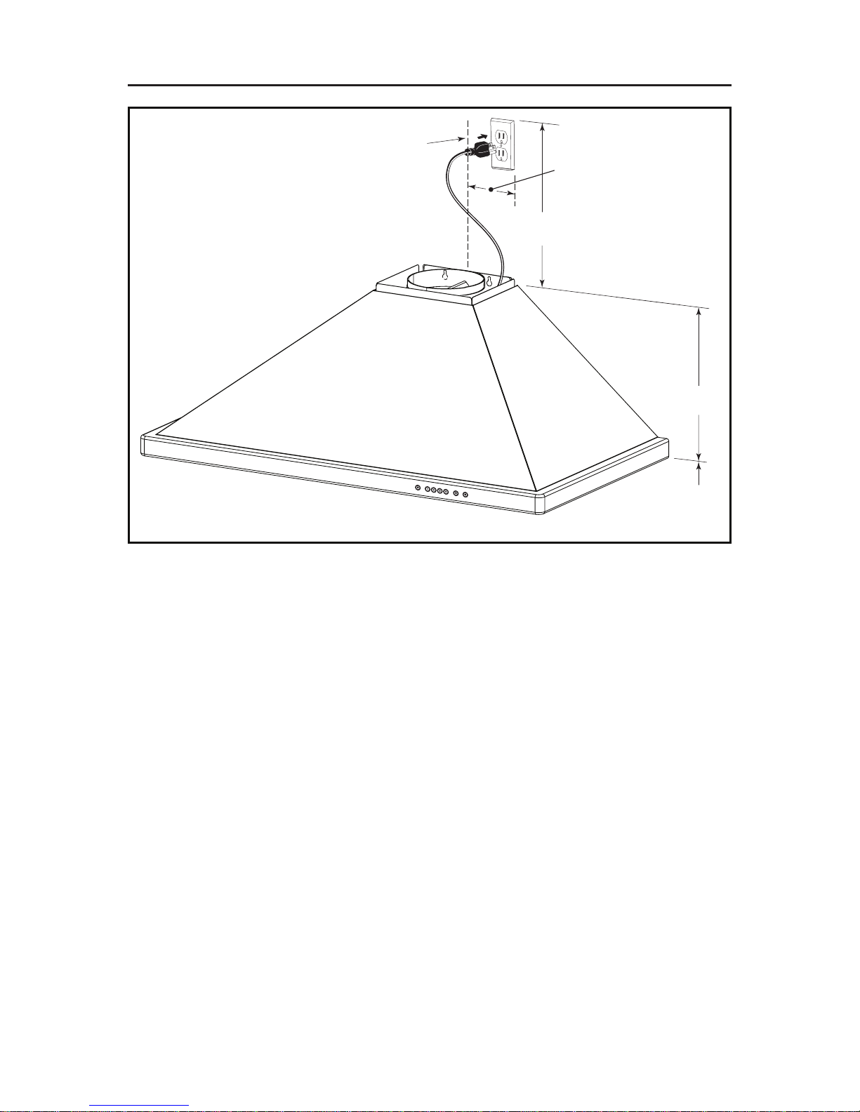
INSTALL THE WIRING
GROUNDING INSTRUCTIONS
This appliance must be grounded. In the event of an electrical short circuit,
grounding reduces the risk of electric shock by providing an escape wire for the
electric current. This appliance is equipped with a cord having a grounding wire
with a grounding plug. The plug must be plugged into an outlet that is properly
installed and grounded.
Position the electrical outlet within the space covered by the decorative flue and
where it will not interfere with the round duct. Make sure the outlet is no further than
24” from the top of the hood chassis, and that the outlet does not interfere with a
mounting bracket fastening area or where the decorative flue touches the wall.
NOTE: A clock outlet can be used to minimize clearance related issues with the
range hood plug.
Page 10
- 10 -
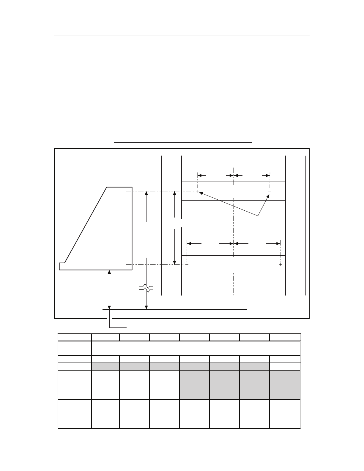
INSTALL THE HOOD MOUNTING SUPPORT
1. Construct structural wall framing that is flush with interior surface of wall studs.
Make sure the framing is centered over installation location.
NOTE
Hood distance above cooktop is: Minimum 24”, Maximum 30”. 9-ft. and 10-ft.
ceilings may require Flue Extension, Model AEWTT32SB (for 30”, 36” & 42” wide
hoods) or Model AEWTT328SB (for 48” wide hoods), depending on installation
height (purchase separately). See charts below for additional installation height
information.
2. After wall surface is finished, fasten (2) 4mm x 38mm screws at the locations
shown below. DO NOT TIGHTEN screws all the way - leave approximately 1/4”
between screw head and wall.
C
L
36” HIGH COOKTOP
11 3/4 ”
6 3/8 ”
4 3/4 ”
4mm x 38mm
SCREWS
HERE
A
SEE
CHART
BELOW
4 3/4 ”
6 3/8 ”
STRUCTURAL
FRAMING
STRUCTURAL
FRAMING
HOOD
24" 25"26" 27" 28"29" 30"
Ceiling
Height
8 Feet 37-1/8" 38-1/8" 39-1/8" 40-1/8"41-1/8"*42-1/8"*43-1/8"
9 Feet
9 Feet
with
AEWTT32SB
10 Feet
with
AEWTT32SB
* Not applicable for non-duct installation.
** For non-duct installation, use upper flue from AEWTT32SB and lower flue from standard hood.
Desired Hood Distance (Above 36" High Cooktop)
43-1/8"
Upper Mounting Screws Location (Distance above 36" High Cooktop)
(Dimension “A”)
**37-1/8" **38-1/8" **39-1/8"
37-1/8" 38-1/8" 39-1/8" 40-1/8"41-1/8"42-1/8" 43-1/8"
For 30-in., 36-in., & 42-in. wide hoods
Page 11
- 11 -
C
L
36” HIGH COOKTOP
10 3/4 ”
7 1/2 ”
4mm x 38mm
SCREWS
HERE
A
SEE
CHART
BELOW
7 1/2 ”
6 3/8 ”6 3/8 ”
STRUCTURAL
FRAMING
STRUCTURAL
FRAMING
HOOD
24" 25"26" 27" 28"29" 30"
Ceiling
Height
8 Feet 36-1/8" 37-1/8" 38-1/8" 39-1/8"40-1/8"41-1/8" 42-1/8"
9 Feet
9 Feet
with
AEWTT328SB
10 Feet
with
AEWTT328SB
Desired Hood Distance (Above 36" High Cooktop)
42-1/8"
Upper Mounting Screws Location (Distance above 36" High Cooktop)
(Dimension “A”)
36-1/8" 37-1/8" 38-1/8"
36-1/8" 37-1/8" 38-1/8" 39-1/8"40-1/8"41-1/8" 42-1/8"
41-1/8"40-1/8"
For 48-in. wide hoods
Page 12
- 12 -
Flush with
the ceiling
Center of
installation
Upper flue mounting
bracket slots
Ceiling
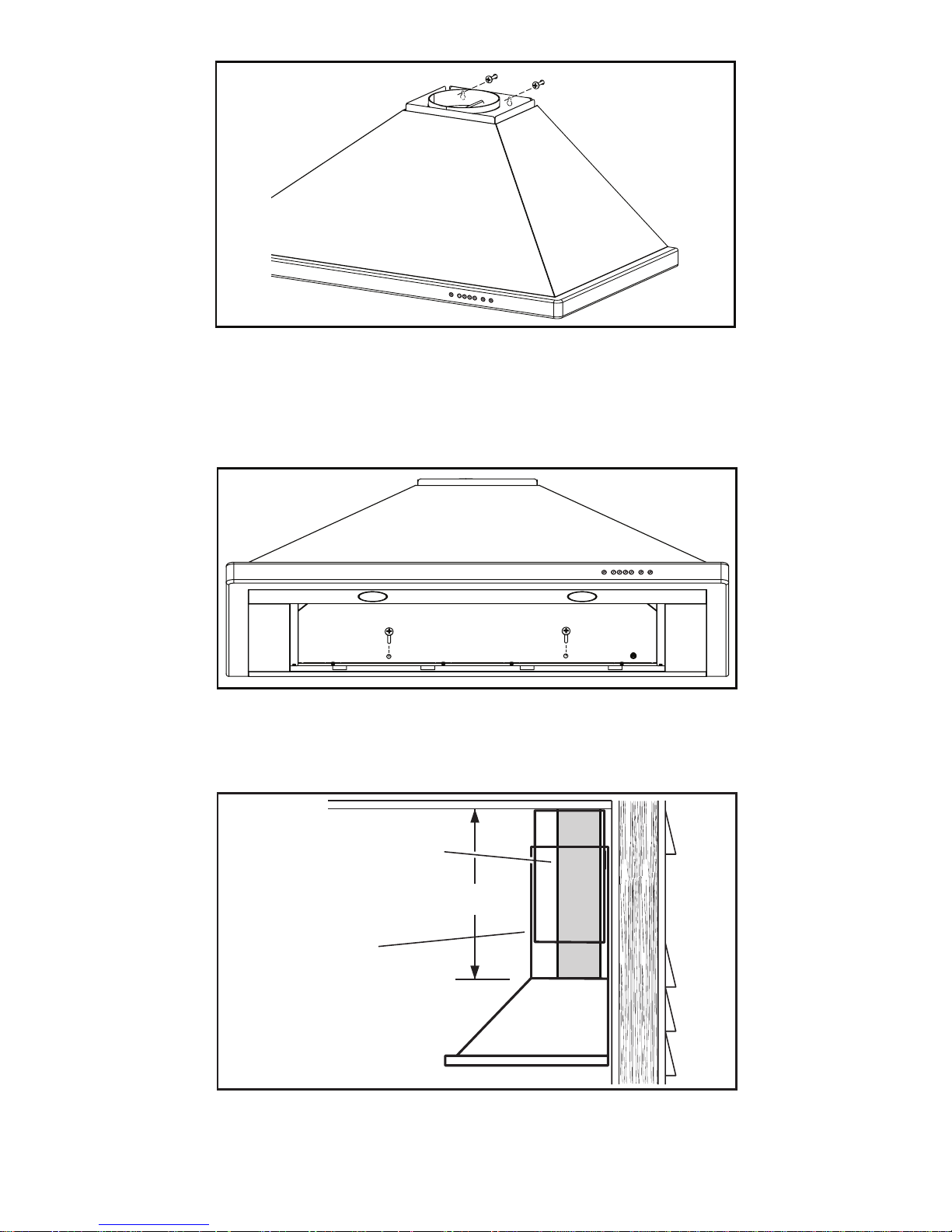
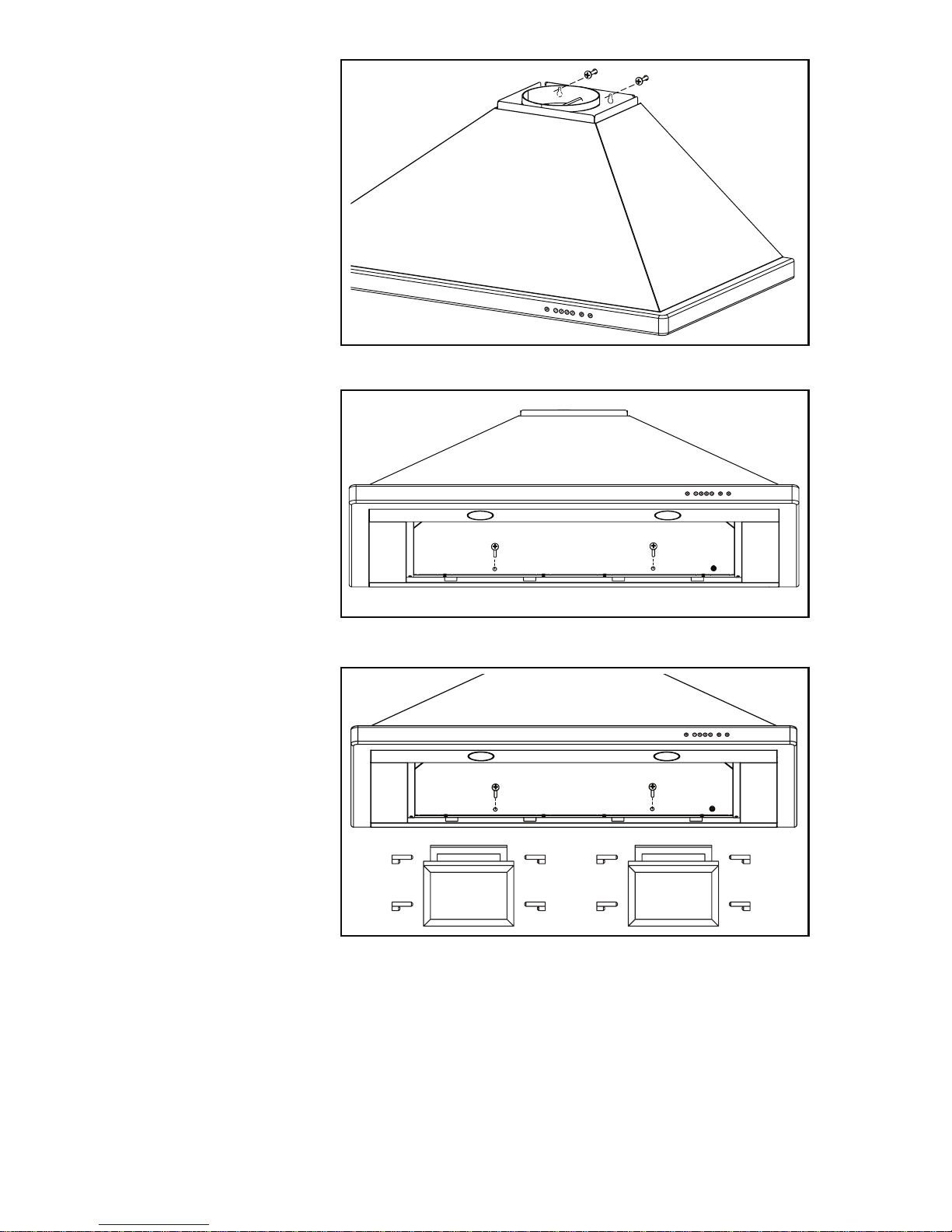
INSTALL THE HOOD
(Ducted Hoods Only)
1. Center the flue mounting bracket over the hood location and flush with the
ceiling. Secure the upper flue bracket to the wall using (2) 4mm x 38mm
mounting screws. Note: Drywall anchors may be required (not included).
2. Tighten the screws completely. Make sure that the bracket is tight against the
wall and ceiling.
3. Remove the protective plastic film covering the decorative flue and the hood at
this time.
4. Remove the grease filters by pulling down the metal latch tab and tilting filters
downward to remove.
5. Remove all internal foam fillers that support the blower assembly inside the
hood.
6. For 48” wide hood only: Attach damper / diverter to top of hood using (2) 4mm
x 8mm mounting screws.
7. Attach the damper / duct connector (8” diameter for 30”, 36”, and 42” wide hoods
and 10” diameter for 48” wide hood) using (4) 4mm x 8mm mounting screws.
C
L
Page 13
- 13 -
DUCT LENGTH
DECORATIVE
FLUE
8” ROUND STEEL DUCT
(10” for 48” wide hood)
8. Align the two outer keyhole slots on the hood with the mounting screws that
were partially tightened into the wall framing. Ensure that hood is seated entirely
on mounting screws and that hood is level. Then tighten screws completely.
9. Install (2) 4mm x 38mm long screws into the holes inside the hood and tighten
them securely.
10. Reinstall grease filters by aligning rear filter tabs with slots in the hood. Pull
down the metal latch tab, push filters into position and release. Make sure
filters are securely engaged after installation.
11. Measure and install steel ductwork to hood duct connector and ductwork
rough-in on ceiling or wall. Use duct tape to make all joints secure and air tight.
12. Plug power cord into wall outlet.
Page 14
- 14 -
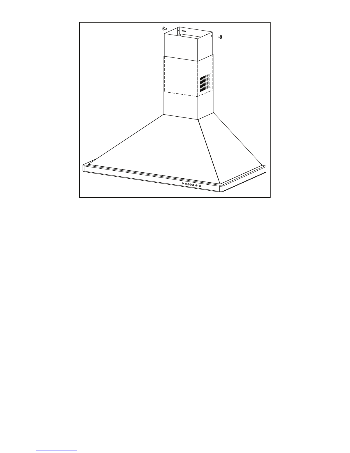
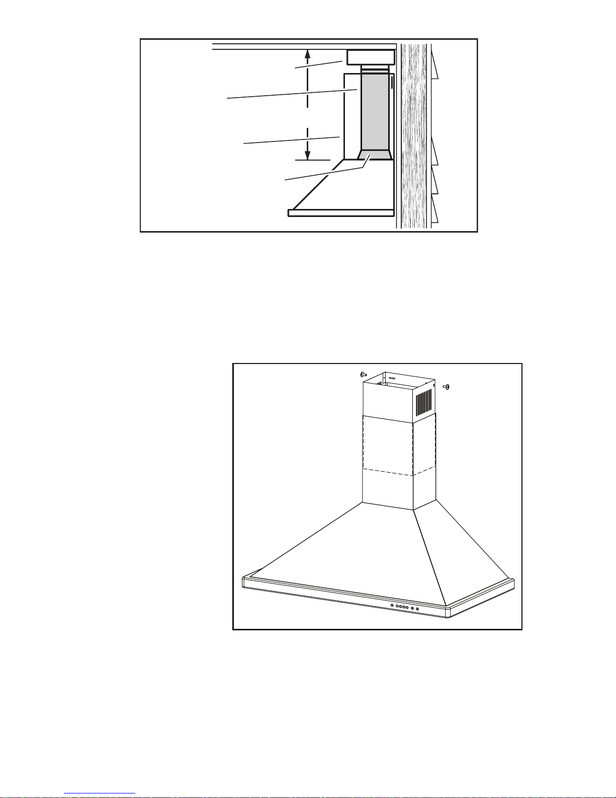
13. Slide the upper decorative flue section into the lower decorative flue section.
NOTE
For ducted applications, the louvers on the upper flue should be hidden by
positioning the louvers down, inside of the lower flue.
14. Carefully place the upper/lower flue assembly into the recessed area of the
hood.
15. Slide the upper flue upward until it is aligned with its mounting bracket. The
bracket should be inside the flue. Secure the upper flue to the upper flue
mounting bracket using (2) 4mm x 12mm mounting screws.
NOTE
9-10 ft. ceilings may require Flue Extension Model AEWTT32SB (for 30”, 36”
& 42” wide hoods) or Model AEWTT328SB (for 48” wide hoods), depending
on installation height (purchase separately). Discard the upper and lower flues
supplied with your hood and replace them with Flue Extensions.
Page 15
- 15 -
INSTALL THE HOOD
(Non-Ducted Hoods Only)
NON-DUCT KIT MODEL ANKWTT320 OR ANKWTT326 CONTENTS
NOTE
Non-ducted installations
require Non-Duct Kit,
Model ANKWTT320 (for
30” wide hood) or Model
ANKWTT326 (for 36” or 42”
wide hood).
1. Center the non-duct
plenum over the hood
location and flush with
the ceiling. Secure the
non-duct plenum to the
wall using (2) 4mm x
38mm mounting screws.
Note: Drywall anchors
may be needed (not
included).
2. Tighten the screws
completely. Make
sure that the non-duct
plenum is tight against
the wall and ceiling.
3. Remove damper flaps
from damper / duct
connector and discard
flaps.
4. Remove the protective
plastic film covering the decorative flue and the hood at this time.
5. Attach the 8” round duct connector to the top of the hood using (4) 4mm x
8mm mounting screws.
6. Remove the grease filters by pulling down the metal latch tab and tilting filters
downward to remove.
7. Remove all internal foam fillers that support the blower assembly inside the
hood.
FLEXIBLE DUCT
NON-DUCTED RECIRCULATION FILTERS
NON-DUCT PLENUM
ASSEMBLY
2 MOUNTING
SCREWS
(4mm x 38mm
Cross Recessed
Pan Head)
8 FILTER CLIPS
L
C
Flush with
the ceiling
Center of
installation
Upper flue mounting
bracket slots
Ceiling
Page 16
- 16 -
8. Align the two
outer keyhole
slots on the hood
with the mounting
screws that were
partially tightened
into the wall
framing. Ensure
that hood is
seated entirely on
mounting screws
and that hood is
level. Then tighten
screws completely.
9. Install (2) 4mm
x 38mm long
screws into the
holes inside the
hood and tighten
them securely.
10. Attach non-
ducted filters to
grease filter using
(8) filter clips.
11. Reinstall grease/
non-duct filter
assembly by
aligning rear filter
tab with slots in
the hood. Pull
down the metal
latch tab, push
filters into position and release. Make sure filters are securely engaged after
installation.
Page 17
- 17 -
12. Measure and install section of flexible metal ductwork (included with
ANKWTT320 or ANKWTT326) to damper/duct connector and bottom of nonduct plenum. Use duct tape to make all joints secure and air tight.
CAUTION
Do not use plastic duct.
13. Plug power cord into wall outlet.
14. Slide the upper decorative flue section into the lower decorative flue section.
NOTE
For non-ducted
applications, the
upper flue should
be oriented so the
louvers are towards
the ceiling.
15. Carefully place the
upper/lower flue
assembly into the
recessed area of
the hood.
16. Slide the upper
flue upward until it
is aligned with the
non-duct plenum.
The non-duct
plenum should
be inside the flue.
Secure the upper
flue to the non-duct
plenum using (2) 4mm x 12mm mounting screws.
NOTE
9-10 ft. ceilings may require Flue Extension Model AEWTT32SB depending
on installation height (purchase separately). Discard the upper and lower
flues supplied with your hood and replace them with Flue Extension Model
AEWTT32SB.
DUCT LENGTH
DECORATIVE
FLUE
8” ROUND
FLEXIBLE
METAL DUCT
NON-DUCT
PLENUM
DAMPER / DUCT
CONNECTOR
Page 18

- 18 -
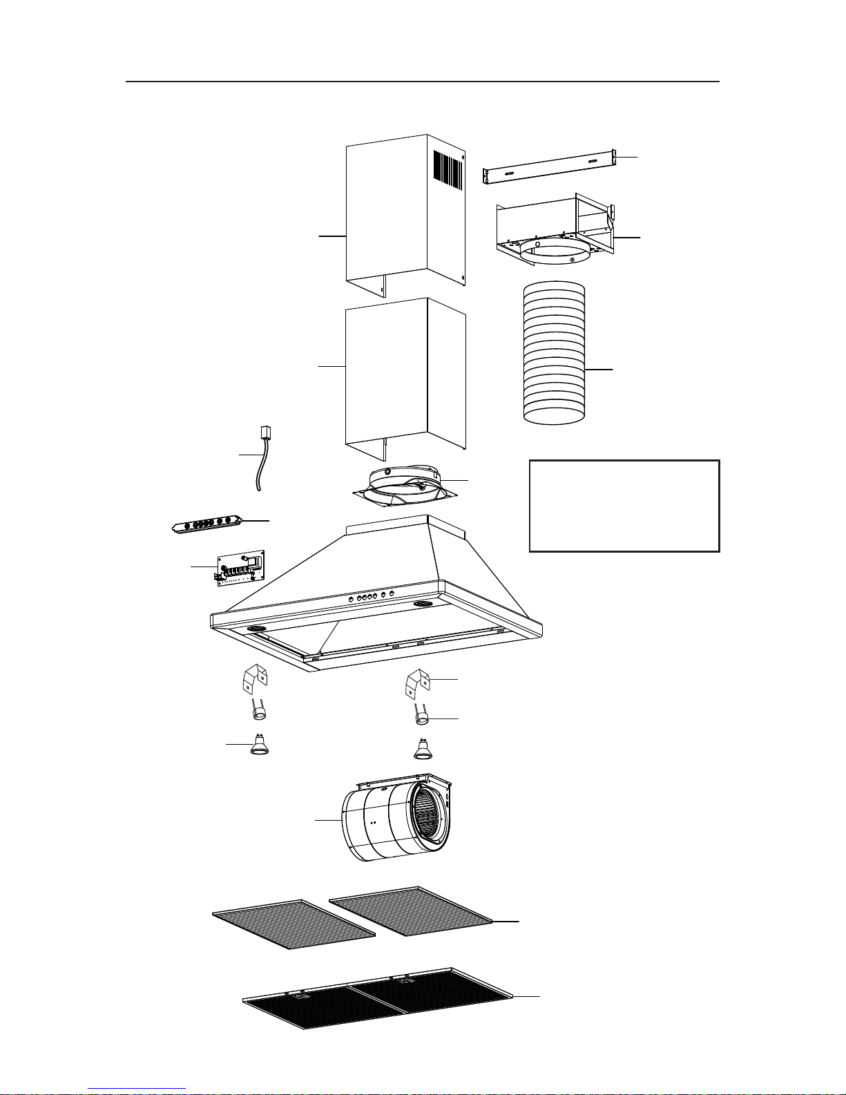
SERVICE PARTS
KEY PART NO. DESCRIPTION QTY.
1 S99528405 Decorative Upper and Lower Flues 1
2 S99528407 Motor / Blower Assembly 1
3 S99528408 Light Socket (30” & 36” wide hoods) 2
(includes mounting hardware)
Light Socket (42” wide hood) 3
(includes mounting hardware)
4 S99528409 Light Socket Bracket (30” & 36” wide hoods) 2
(includes mounting hardware)
Light Socket Bracket (42” wide hood) 3
(includes mounting hardware)
5 S99528410 User Interface Assembly 1
6 S99528411 User Interface Cable 1
7 S99528412 Control Board 1
8 S99528414 Aluminum Grease Filter (30” wide hood) 2
S99528415 Aluminum Grease Filter (36” & 42” wide hoods) 2
9 S97018968 Non-Duct Recirculation Filter (30” wide hood) 2
S97019039 Non-Duct Recirculation Filter (36” & 42” wide hoods) 2
10 S99528418 8” Damper Assembly 1
11 S99528429 8” Dia. Expandable Flexible Aluminum Duct 1
12 S99528421 Non-Duct Plenum Assembly 1
13 S99528422 Upper Flue Mounting Bracket 1
14 V05921 50W MR16 GU10 Halogen Lamp (30” & 36” wide hoods) 2
50W MR16 GU10 Halogen Lamp (42” wide hood) 3
* S99528423 Capacitor 1
* S99528425 Parts Bag 1
* Not shown.
Order service parts by Part No. - not by Key No.
30”, 36” & 42” Wide Models
Page 19
- 19 -
Replacement parts can be
ordered on our website:
www.BestRangeHoods.com
SERVICE PARTS
1
2
5
7
8
9
10
12
14
3
4
11
6
1
13
30”, 36” & 42” Wide Models
Page 20

- 20 -
SERVICE PARTS
48” Wide Model
KEY PART NO. DESCRIPTION QTY.
1 S99528406 Decorative Upper and Lower Flues 1
2 S99528407 Motor / Blower Assembly 2
3 S99528408 Light Socket 3
(includes mounting hardware)
4 S99528409 Light Socket Bracket 3
(includes mounting hardware)
5 S99528410 User Interface Assembly 1
6 S99528411 User Interface Cable 1
7 S99528413 Control Board 1
8 S99528414 Aluminum Grease Filter 3
9 S99528419 10” Damper Assembly 1
10 S99528420 Diverter 1
11 S99528438 Upper Flue Mounting Bracket 1
12 V05921 50W MR16 GU10 Halogen Lamp 3
* S99528423 Capacitor 2
* S99528430 Parts Bag 1
* Not shown.
Order service parts by Part No. - not by Key No.
Page 21
- 21 -
Replacement parts can be
ordered on our website:
www.BestRangeHoods.com
SERVICE PARTS
6
1
11
5
7
8
10
2
9
12
3
4
1
48” Wide Model
Page 22

- 22 -
WARRANTY
ONE YEAR LIMITED WARRANTY FOR BEST PRODUCTS
Broan-NuTone LLC (Broan-NuTone) warrants to the original consumer purchaser
of Best products that such products will be free from defects in materials or workmanship for a period of one year from the date of original purchase. THERE ARE
NO OTHER WARRANTIES, EXPRESS OR IMPLIED, INCLUDING, BUT NOT
LIMITED TO, IMPLIED WARRANTIES OR MERCHANT ABILITY OR FITNESS
FOR A PARTICULAR PURPOSE.
During this one-year period, Broan-NuTone will, at its option, repair or replace,
without charge, any product or part which is found to be defective under normal
use and service.
THIS WARRANTY DOES NOT EXTEND TO FLUORESCENT LAMP STARTERS,
TUBES, HALOGEN AND INCANDESCENT BULBS, FUSE, FILTERS, DUCTS,
ROOF CAPS, WALL CAPS AND OTHER ACCESSORIES FOR DUCTING. This
warranty does not cover (a) normal maintenance and service or (b) any products
or parts which have been subject to misuse, negligence, accident, improper
maintenance or repair (other than by Broan-NuTone), faulty installation or installation contrary to recommended installation instructions.
The duration of any implied warranty is limited to the one-year period as specified for the express warranty. Some states do not allow limitation on how long an
implied warranty lasts, so the above limitation may not apply to you.
BROAN-NUTONE’S OBLIGATION TO REPAIR OR REPLACE, AT BROANNUTONE’S OPTION, SHALL BE THE PURCHASER’S SOLE AND EXCLUSIVE
REMEDY UNDER THIS WARRANTY. BROAN-NUTONE SHALL NOT BE LIABLE
FOR INCIDENTAL, CONSEQUENTIAL OR SPECIAL DAMAGES ARISING OUT
OF OR IN CONNECTION WITH PRODUCT USE OR PERFORMANCE. Some
states do not allow the exclusion or limitation of incidental or consequential damages, so the above limitation or exclusion may not apply to you.
This warranty gives you specific legal rights, and you may also have other rights,
which vary from state to state. This warranty supersedes all prior warranties.
To qualify for warranty service, you must (a) notify Broan-NuTone at the address
stated below or telephone number stated below, (b) give the model number and
part identification and (c) describe the nature of any defect in the product or
part. At the time of requesting warranty service, you must present evidence of
the original purchase date.
In USA - BEST®, 926 W. State Street, Hartford, WI 53027 (800-558-1711)
In Canada - BEST®, 550 Lemire Blvd., Drummondville, QC J2C 7W9 (866-737-7770)
www.BestRangeHoods.com
99045047B
Page 23

Série WTT32I
Aux États-Unis - BEST® Hartford, Wisconsin
RENREGISTREZ VOTRE PRODUIT EN LIGNE À : www.BestRangeHoods.com/register
Pour de plus amples informations, visitez www.BestRangeHoods.com
HB0103
Page 24

- 24 -
LIRE CES DIRECTIVES ET LES CONSERVER
AVERTISSEMENT
AFIN DE RÉDUIRE LES RISQUES D’INCENDIE, DE DÉCHARGES ÉLECTRIQUES
OU DE BLESSURES CORPORELLES, VEUILLEZ OBSERVER LES DIRECTIVES
SUIVANTES :
1. N’utilisez cet appareil que de la manière prévue par le fabricant. Si vous avez
des questions, communiquez avec le fabricant à l’adresse ou au numéro de
téléphone indiqués dans la garantie.
2. Avant de procéder à l’entretien ou au nettoyage de l’appareil, coupez
l’alimentation du panneau électrique et verrouillez l’interrupteur principal afin
d’empêcher que le courant ne soit accidentellement rétabli. S’il est impossible de
verrouiller l’interrupteur principal, fixez solidement un message d’avertissement,
par exemple une étiquette, sur le panneau électrique.
3. L’installation et les branchements électriques doivent être effectués par un
personnel compétent, conformément aux normes et aux codes en vigueur,
ycompris les normes et les codes du bâtiment relatifs à la résistance au feu.
4. Pour éviter les refoulements, l’apport d’air doit être suffisant pour brûler les
gaz produits par les appareils à combustion et les évacuer dans le conduit
de fumée (cheminée). Respectez les directives du fabricant de l’appareil de
chauffage et les normes de sécurité, notamment celles publiées par la National
Fire Protection Association (NFPA), l’American Society for Heating, Refrigeration
and Air Conditioning Engineers (ASHRAE) et les codes des autorités locales.
5. Ce produit peut comporter des arêtes tranchantes. Prenez garde aux coupures
et aux éraflures lors de l’installation et du nettoyage.
6. Veillez à ne pas endommager le câblage électrique ou d’autres équipements
non apparents lors de la découpe ou du perçage du mur ou du plafond.
7. Les ventilateurs canalisés doivent toujours rejeter l’air à l’extérieur.
8. Pour réduire les risques d’incendie, utilisez seulement des conduits en acier.
9. N’utilisez pas de commande de régime à semi-conducteurs avec cet appareil.
10. Ne faites pas fonctionner le ventilateur si le cordon électrique ou la fiche est
endommagé. Jetez le ventilateur ou rapportez-le chez un réparateur agréé pour
le faire examiner et/ou réparer.
11. DIRECTIVES DE MISE À LA TERRE : Cet appareil doit être mis à la terre. Dans
l’éventualité d’un court-circuit, la mise à la terre réduit les risques de décharge
électrique en permettant au courant de s’échapper dans un fil. Cetappareil
comporte un cordon électrique muni d’un fil et d’une fiche de mise à la terre.
Cette fiche doit être branchée dans une prise de courant correctement installée
et mise à la terre. AVERTISSEMENT : Une mise à la terre incorrecte peut
entraîner un risque de choc électrique. Consultez un électricien qualifié si vous
ne comprenez pas complètement les directives de mise à la terre ou si vous
n’êtes pas sûr que l’appareil comporte une mise à la terre adéquate. N’utilisez
pas de rallonge électrique. Si le cordon électrique est trop court, demandez à
un électricien qualifié d’installer une prise de courant près de l’appareil.
!
POUR USAGE DOMESTIQUE SEULEMENT
!
Page 25

- 25 -
!
ATTENTION
1. Pour usage intérieur seulement.
2. Pour ventilation générale uniquement. N’utilisez pas cet appareil pour évacuer des
matières ou des vapeurs dangereuses ou explosives.
3. Pour ne pas endommager les roulements du moteur, déséquilibrer les pales ou les
rendre bruyantes, protégez l’appareil de la poussière de plâtre, de construction, etc.
4. Le moteur de la hotte est muni d’un dispositif de protection thermique qui coupe
automatiquement le moteur en cas de surchauffe. Il se remet en marche lorsqu’il a
refroidi. Faites réparer la hotte si le moteur continue à fonctionner par intermittence.
5. Pour mieux capter les vapeurs de cuisson, le bas de la hotte DOIT ÊTRE AU MINIMUM
à 61 cm (24 po) et au maximum à 76,2 cm (30 po) au-dessus de la surface de cuisson
6. Il est recommandé que les installateurs soient deux, compte tenu de la taille de cette hotte.
7. Pour réduire les risques d’incendie et évacuer l’air correctement, assurez-vous qu’il
est canalisé à l’extérieur. Ne pas évacuer l’air dans des espaces enfermés par des
murs ou un plafond ou dans un grenier, un vide sanitaire ou un garage.
8. Prenez garde en installant la cheminée décorative et la hotte, car elles peuvent
comporter des bords tranchants.
9. Veuillez lire l’étiquette de spécifications du produit pour obtenir plus de renseignements,
notamment sur les exigences.
POUR RÉDUIRE LES RISQUES D’INCENDIE CAUSÉS PAR DE LA GRAISSE SUR
LE PLAN DE CUISSON :
a) Ne laissez jamais les éléments de surface allumés à haute température. Les
débordements peuvent causer de la fumée et occasionner des écoulements de
graisse inflammables. L’huile doit être chauffée graduellement à basse ou à moyenne
température.
b) Mettez toujours la hotte en MARCHE lors de la cuisson à feu vif ou lors de la cuisson
d’aliments à flamber (crêpes Suzette, cerises jubilé, bœuf au poivre flambé).
c) Nettoyez souvent la hotte. Ne laissez pas la graisse s’accumuler sur le ventilateur
ou les filtres.
d) Utilisez des casseroles de dimension appropriée. Utilisez toujours une batterie de
cuisine adaptée à la dimension de la surface chauffante.
OBSERVEZ LES CONSIGNES SUIVANTES AFIN DE RÉDUIRE LES RISQUES DE
BLESSURES CORPORELLES EN CAS D’INCENDIE CAUSÉ PAR DE LA GRAISSE
SUR LE PLAN DE CUISSON :*
1. ÉTOUFFEZ LES FLAMMES à l’aide d’un couvercle étanche, d’une tôle à biscuits
ou d’un plateau en métal puis éteignez le brûleur. FAITES ATTENTION DE NE PAS
VOUS BRÛLER. SI LES FLAMMES NE S’ÉTEIGNENT PAS IMMÉDIATEMENT,
QUITTEZ LES LIEUX ET APPELEZ LE SERVICE DES INCENDIES.
2. NE SOULEVEZ JAMAIS UNE CASSEROLE EN FLAMMES – vous pourriez vous brûler.
3. N’UTILISEZ PAS D’EAU, ni de linges ou de serviettes mouillés – une violente
explosion de vapeur pourrait survenir.
4. Utilisez un extincteur SEULEMENT si :
A. Vous savez qu’il est de classe ABC et vous connaissez déjà son mode de
fonctionnement.
B. L’incendie n’est pas très important et ne se propage pas.
C. Vous avez déjà téléphoné au service des incendies.
D. Vous pouvez combattre l’incendie en faisant dos à une sortie.
* Conseils tirés de la publication de la NFPA « Kitchen Fire Safety Tips ».
Page 26

- 26 -
FONCTIONNEMENT
Mettez toujours la hotte en marche avant de cuisiner afin d’établir une circulation d’air
dans la cuisine. Laissez la hotte fonctionner quelques minutes après l’arrêt de la cuisinière
afin de nettoyer l’air.
La hotte fonctionne à l’aide de boutons-poussoirs situés sur la face avant.
A. BOUTON DE MINUTERIE
Lorsqu’une vitesse de ventilateur est sélectionnée, appuyez sur ce bouton pour
activer la fonction d’arrêt différé. Le bouton d’arrêt différé s’illuminera pour indiquer
que cette fonction est activée. Le ventilateur continuera de fonctionner pendant cinq
minutes puis d’arrêtera automatiquement. Pour annuler la fonction d’arrêt différé,
appuyez de nouveau sur le bouton deminuterie.
B. BOUTONS MARCHE / ARRÊT DE SÉLECTION DE VITESSE
Appuyez sur le bouton correspondant à la vitesse de ventilateur voulue (1 pour lent
à 4 pour rapide). Le bouton choisi s’illuminera. Pour arrêter le ventilateur, appuyez
de nouveau sur le bouton correspondant à la vitesse du ventilateur; le bouton
s’éteindra.
C. BOUTON MAÎTRE D’ARRÊT / D’ENTRETIEN DU FILTRE / DE DÉTECTEUR
HEATSENTRY™ (BOUTON À TRIPLE FONCTION)
Pour arrêter le ventilateur et éteindre simultanément l’éclairage, appuyez une fois
sur ce bouton. Après 25 heures d’utilisation, ce bouton s’illuminera pour indiquer
que les filtres et la ou les roues à ailettes du ventilateur doivent être nettoyés pour
maintenir l’efficacité de la hotte. Le bouton restera allumé jusqu’à la remise à zéro
de cette fonction en appuyant sur le bouton pendant 3 secondes. Le voyant lumineux
indique également la mise en fonction du détecteur de chaleur Heat Sentry.
DÉTECTEUR DE CHALEUR HEAT SENTRY : Lorsqu’une température trop élevée
est détectée, la fonction Heat Sentry prend le contrôle du ventilateur et le règle à la
vitesse 3. L’interrupteur à triple fonction se met à clignoter. Le ventilateur demeurera
en marche jusqu’à ce que la chaleur soit revenue à la normale. Il reprendra alors la
vitesse préalablement choisie.
AVERTISSEMENT : Le détecteur Heat Sentry peut faire démarrer
le ventilateur même si la hotte est arrêtée. Lorsque cela se produit,
ilest impossible d’arrêter le ventilateur en appuyant sur les boutons.
Sivous devez arrêter le ventilateur, coupez le disjoncteur du panneau
d’alimentationélectrique.
D. INTERRUPTEUR D’ÉCLAIRAGE
Cet interrupteur offre trois niveaux d’éclairage selon vos besoins. Appuyez une
fois pour la veilleuse de nuit, deux fois pour l’éclairage normal ou trois fois pour
l’intensité maximale. Pour éteindre les lumières sans arrêter le ventilateur, appuyez
une fois de plus.
A B C D
Page 27

- 27 -
CLAPET D'AIR DE
COMPENSATION
HOTTE
TRANSFORMATEUR
24V (INCLUS)
FIL DE
TERRE
MANCHON DE
BORNE DE CONTAC
T
SEC POUR
CONNEXION
BASSE TENSION
120 VCA
60 HZ
CONNEXION DU CLAPET D'AIR
DE COMPENSATION
(à interrupteur à basse tension)
FIL DE SONNETTE DE CALIBRE
20 POUR UNE CONNEXION
BASSE TENSION AU-DESSUS
DE LA HOTTE
CLAPET D’AIR DE COMPENSATION
La hotte est compatible avec le Clapet d’air de compensation Broan modèle MD6T ou modèle
MD8T (en option). Vendu séparément.
Connectez le clapet d’air de compensation avec des fils de basse tension, tel qu’illustré.
Pourde plus amples renseignements, consultez les directives du clapet d’air de compensation.
Page 28

- 28 -
NETTOYAGE ET ENTRETIEN
Pour des raisons de santé, de performance et d’apparence, nettoyez régulièrement le filtre, le
ventilateur et les surfaces graisseuses. Utilisez seulement un chiffon propre et une solution de
détergent doux sur l’acier inoxydable et les surfaces peintes.
Nettoyez les filtres entièrement métalliques au lave-vaisselle avec un détergent sansphosphate.
Une décoloration du filtre peut se produire si des détergents phosphatés sont utilisés et selon
les conditions locales de l’eau, sans toutefois affecter le rendement du filtre. Cette décoloration
n’est pas couverte par la garantie.
Nettoyez souvent les surfaces des filtres de recirculation avec un linge humide et un
détergentdoux. NE PLONGEZ PAS les filtres dans l’eau et ne les mettez pas au lave-vaisselle.
Remplacez les filtres de recirculation sans conduit tous les six mois. Pour remplacer les filtres
de recirculation - veuillez acheter les filtres S97018968 ou Modèle AFCWTT32 pour les hottes
de 76,2 cm (30 po) de largeur, ou les filtres S97019039 ou Modèle AFCWTT326 pour les
hottes de 91,4 cm (36 po) ou de 106,7 cm (42 po) de largeur.
Le moteur est lubrifié en permanence et n’a pas besoin d’être huilé. Si les roulements du moteur sont
anormalement bruyants, remplacez l’ensemble du ventilateur exactement par le même modèle.
AMPOULES
AVERTISSEMENT :
Les ampoules peuvent
être très chaudes. Laissez
toujours les ampoules
refroidir avant de les
enlever.
Utilisez deux (2) ampoules
halogènes (fournies
avec la hotte) (ampoules
halogènes avec écran de
120 V, 50W - MR16 à culot
GU10. (3 ampoules pour
les hottes de 106,7cm (42
po) et121,9 cm (48po).)
REMARQUE :
Vous pouvez utiliser la ventouse (fournie avec la hotte) pour installer ou enlever les ampoules.
Alignez les bornes de l’ampoule sur la grande ouverture du socle, puis poussez l’ampoule
vers lahotte et tournez-la dans le sens horaire jusqu’à ce qu’elle soit bien appuyée. La position
du socle de l’ampoule (sa profondeur) est réglable et peut exiger un ajustement lorsque : a)
certainesmarques d’ampoule
sont difficiles à installer. b)
l’ampoule dépasse trop sous le
panneau d’éclairage.
SUPPORT DE
SOCLED’AMPOULE
VIS
PANNEAU
D’ÉCLAIRAGE
Pour changer la profondeur des
socles d’ampoule :
- Enlevez les vis du panneau
d’éclairage et mettez-les de côté.
- Enlevez le panneau d’éclairage.
- Desserrez les 2 vis retenant le
support du socle d’ampoule au
panneau d’éclairage.
- Réglez le support / socle à la
profondeur voulue.
- Resserrez les vis fermement.
- Fixez à nouveau le panneau
d’éclairage avec les vis que
vous avez mises de côté.
(1)
ENFONCER
(2)
TOURNER DANS
LE SENS HORAIRE
VENTOUSE
AMPOULE
HALOGÈNE
Page 29

- 29 -
POSE DU CONDUIT
(Hottes avec conduit seulement)
1. Planifiez la pose du conduit en déterminant son tracé entre la hotte et l’extérieur
dela maison.
2. Un tracé droit et court permet à la hotte d’être plus efficace.
3. Des conduits longs, des coudes et des transitions réduisent l’efficacité de la hotte.
N’en utilisez que le moins possible. Pour plus d’efficacité, des conduits plus gros
peuvent être nécessaires si le parcours est trop long.
4. Installez le capuchon mural ou de toit. Connectez un conduit rond en métal au
capuchon en progressant vers la hotte. Scellez les joints avec du ruban à conduit
àchaque section.
MESURES DE L’INSTALLATION
La distance minimale de la hotte au-dessus de la surface de cuisson NE DOIT PAS
ÊTRE INFÉRIEURE à 61 cm (24 po).
Un maximum de 76,2 cm (30 po) est également fortement recommandé pour mieux
capter les vapeurs de cuisson.
Une distance de plus de 76,2 cm (30 po) est laissée à la discrétion de l’installateur et
des utilisateurs si la hauteur du plafond le permet.
HOTTE
33,3 CM (13 1/8 PO)
AU CENTRE DES TROUS
DE MONTAGE SUPÉRIEURS
COUDE ROND
BRIDE DE MONTAGE
DE HOTTE
61 CM (24 PO) À 76,2 CM (30 PO)
AU-DESSUS DE LA SURFACE
DE CUISSON
CONDUIT DÉCORATIF
CONDUIT ROND
DE 20,3 CM (8 PO)
CAPUCHON DE TOIT
CAPUCHON MURAL
3,5 CM (1 3/8 PO)
AU CENTRE DES
TROUS INFÉRIEURS
DU CHÂSSIS DE
LA HOTTE
11,1 CM (4 3/8 PO)
DU MUR À LA LIGNE
CENTRALE DU CONDUIT
CONDUIT DÉCORATIF
HOTTE
30,8 CM (12 1/8 PO)
AU CENTRE DES
TROUS DE MONTAGE
SUPÉRIEURS
COUDE ROND
BRIDE DE MONTAGE
DE HOTTE
61 CM (24 PO)
À 76,2 CM (30 PO)
AU-DESSUS DE LA SURFACE
DE CUISSON
CONDUIT DÉCORATIF
CONDUIT ROND
DE 25,4 CM (10 PO)
CAPUCHON DE TOIT
CAPUCHON MURAL
3,5 CM (1 3/8 PO)
AU CENTRE DES
TROUS INFÉRIEURS
DU CHÂSSIS DE
LA HOTTE
16,7 CM (6 9/16 PO)
DU MUR À LA
LIGNE CENTRALE
DU CONDUIT
CONDUIT DÉCORATIF
Pour hottes de 76,2 cm, 91,4 cm et
106,7 cm (30 po, 36 po et 42 po)
Pour hottes de 121,9 cm (48 po)
Page 30

- 30 -
PRÉPARATION DE LA HOTTE
Déballez la hotte et vérifiez le contenu de la boîte. Celle-ci doit contenir les éléments suivants:
1 - Ensemble de hotte
1 - Ensemble de conduit décoratif (sections supérieure et inférieure)
1 - Bride de montage de conduit décoratif supérieur
2 - Filtres à graisses en aluminium (installés dans la hotte) (2 – pour modèles
de121,9cm / 48 po)
2 - Ampoules halogènes de 50W MR16 GU10 (installées dans la hottes)
(3 – pour modèles de 106,7 cm / 42 po et 121,9 cm / 48 po)
1 - Clapet / raccord de conduit de 20,3 cm (8 po) (pour modèles de 76,2 cm / 30 po,
91,4 cm / 36 po, 106,7 cm / 42 po)
1 - Clapet / raccord de conduit de 25,4 cm (10 po) (pour modèle de 121,9 cm / 48 po)
1 - Déflecteur de clapet (pour modèle de 121,9 cm / 48 po)
1 - Sac de pièces contenant :
6 - Vis de montage (4 mm x 38 mm à tête cylindrique cruciforme)
4 - Vis de montage (4mm x 8 mm à tête cylindrique cruciforme) (6 vis pour le modèle
de 121,9 cm / 48 po)
1 - Ventouse (pour la pose et l’enlèvement de l’ampoule)
6 VIS DE MONTAGE
(4 x 38 mm à tête
cylindrique cruciforme)
2 VIS DE MONTAGE
(4 x 12 mm à tête
cylindrique cruciforme)
ENSEMBLE
DE CONDUIT
DÉCORATIF
DE CHEMINÉE
BRIDE DE MONTAGE
DE CONDUIT DÉCORATIF
SUPÉRIEUR
VENTOUSE
POUR AMPOULE
ENSEMBLE
DE HOTTE
1 - CLAPET / RACCORD
DE CONDUIT 20,3 cm (8 po) dia.
pour modèles de 76,2 cm (30 po),
91,4 cm (36 po) et 106,7 cm (42 po)
et 25,4 cm (10 po) dia.
pour modèle de 121,9 cm (48 po)
1 - DÉFLECTEUR DE CLAPET
(modèle de 121,9 cm
(48 po) seulement)
4 VIS DE MONTAGE
(4 x 8 mm à tête
cylindrique cruciforme)
(6 pour modèle de
121,9 cm (48 po))
Page 31

- 31 -
MAX. 61 CM
(24 PO)
LIGNE CENTRALE
DE LA HOTTE
12,1 CM (4
3
/4 PO)
MODÈLES DE 76,2 CM (30 PO),
91,4 CM (36 PO)
ET 106,7 CM (42 PO)
19,7 CM (7
3
/4 PO)
POUR MODÈLE
121,9 CM (48 PO)
31,4 CM
(12
3
/8 PO)
61 CM (24 PO)
À 91,4 CM (36 PO)
AU-DESSUS DE LA
SURFACE DE CUISSON
INSTALLATION DU CÂBLAGE
INSTRUCTIONS DE MISE À LA TERRE
Cet appareil doit être correctement mis à la terre. Dans l’éventualité d’un court-circuit,
la mise à la terre réduit les risques de décharge électrique en permettant au courant
de s’échapper dans un fil. Cet appareil comporte un cordon électrique muni d’un fil et
d’une fiche de mise à la terre. Cette fiche doit être branchée dans une prise de courant
correctement installée et mise à la terre.
Placez la prise de courant dans l’espace recouvert par le conduit décoratif de cheminée
et à un endroit où elle ne nuira pas au passage du conduit rond. Elle ne doit pas être à
plus de 61 cm (24 po) du dessus de la hotte et ne pas empiéter sur la zone de fixation
d’un support de montage et de l’endroit où le conduit décoratif touche au mur.
REMARQUE : Une prise de courant encastrée pour horloge peut être utilisée minimiser
les problèmes d’encombrement de la fiche de la hotte.
Page 32

- 32 -
INSTALLATION DE LA BRIDE DE MONTAGE
DE LA HOTTE
1. Construisez une charpente de bois qui affleure la surface intérieure des montants
du mur. Centrez cette charpente avec l’emplacement d’installation.
REMARQUE : La distance de la hotte au-dessus de la surface de cuisson est : Au
minimum 61cm (24po), au maximum 76,2 cm (30 po). Les plafonds de 274 cm (9
pi) et 305 cm (10pi) peuvent nécessiter la rallonge de conduit décoratif, modèle
AEWTT32SB pour les hottes de 76,2 cm (30 po), 91,4 cm (36 po) et 106,7 cm (42
po) de largeur, ou le modèle AEWTT328SB pour les hottes de 121,9 cm (48 po)
de largeur, selon la hauteur de l’installation (vendu séparément). Voir le tableau ci-
dessous pour de plus amples informations sur la hauteur de l’installation.
2. Une fois la surface du mur finie, fixez deux (2) vis de 4 mm x 38 mm aux endroits
indiqués ci-dessous. NE SERREZ PAS les vis jusqu’au bout - laissez environ 6,3
mm (1/4 po) entre la tête de la vis et le mur.
C
L
SURFACE DE CUISSON
À 91,4 cm (36 po)
29,8 cm
(11
3
/4 po)
16,2 cm
(6
3
/8 po)
VIS DE
4 mm X 38 mm ICI
A
VOIR LE
TABLEAU
CI-DESSOUS
12,1 cm
(4
3
/4 po)
12,1 cm
(4
3
/4 po)
16,2 cm
(6
3
/8 po)
CHARPENTE
CHARPENTE
HOTTE
61 cm (24 po) 63,5 cm (25 po) 66 cm (26 po) 68,6 cm (27 po) 71,1 cm (28 po) 73,7 cm(29 po) 76,2 cm (30 po)
Hauteur
du plafond
244 cm (8 pi)
94,3 cm
(37-1/8 po)
96,8 cm
(38-1/8 po)
99,4 cm
(39-1/8 po)
101,9 cm
(40-1/8 po)
104,5 cm
(41-1/8 po)
*107 cm
(42-1/8 po)
*109,5 cm
(43-1/8 po)
274 cm (9 pi)
274 cm (9 pi)
avec
AEWTT32SB
305 cm (10 pi)
avec
AEWTT32SB
* Les évents de recirculation sans conduits sont exposés lors d'une installation avec conduits.
** Pour les non-conduit d'installation, utilisez Cheminée supérieure et inférieure de AEWTT32SB
fumées de la hotte standard.
Distance requise pour la hotte au-dessus d’une surface de cuisson située à 91,4 cm (36 po)
109,5 cm
(43-1/8 po)
Position des vis de montage supérieures – distance au-dessus d’une surface de cuisson située
à 91,4 cm (36 po) (Dimension « A »)
**94,3 cm
(37-1/8 po)
**96,8 cm
(38-1/8 po)
**99,4 cm
(39-1/8 po)
94,3 cm
(37-1/8 po)
96,8 cm
(38-1/8 po)
99,4 cm
(39-1/8 po)
101,9 cm
(40-1/8 po)
104,5 cm
(41-1/8 po)
107 cm
(42-1/8 po)
109,5 cm
(43-1/8 po)
Hottes de 76,2 cm (30 po), 91,4 cm (36 po) et 106,7 cm (42 po) de largeur
Page 33

- 33 -
C
L
SURFACE DE CUISSON
À 91,4 cm (36 po)
27,3 cm
(10 3/4 po)
19,1 cm
(7
1
/2 po)
VIS DE
4 mm X 38 mm ICI
A
VOIR LE
TABLEAU
CI-DESSOUS
16,2 cm
(6 3/8 po)
19,1 cm
(7
1
/2 po)
16,2 cm
(6 3/8 po)
CHARPENTE
CHARPENTE
HOTTE
244 cm (8 pi)
274 cm (9 pi)
91,8 cm
(36-1/8 po)
94,3 cm
(37-1/8 po)
96,8 cm
(38-1/8 po)
99,4 cm
(39-1/8 po)
101,9 cm
(40-1/8 po)
104,5 cm
(41-1/8 po)
107 cm
(42-1/8 po)
305 cm (10 pi)
avec
AEWTT32SB
Distance requise pour la hotte au-dessus d’une surface de cuisson située à 91,4 cm (36 po)
61 cm (24 po) 63,5 cm (25 po) 66 cm (26 po) 68,6 cm (27 po) 71,1 cm (28 po) 73,7 cm(29 po) 76,2 cm (30 po)
Hauteur
du plafond
Position des vis de montage supérieures – distance au-dessus d’une surface de cuisson
située à 91,4 cm (36 po) (Dimension « A »)
107 cm
(42-1/8 po)
274 cm (9 pi)
avec
AEWTT32SB
91,8 cm
(36-1/8 po)
94,3 cm
(37-1/8 po)
96,8 cm
(38-1/8 po)
91,8 cm
(36-1/8 po)
94,3 cm
(37-1/8 po)
96,8 cm
(38-1/8 po)
99,4 cm
(39-1/8 po)
101,9 cm
(40-1/8 po)
104,5 cm
(41-1/8 po)
107 cm
(42-1/8 po)
101,9 cm
(40-1/8 po)
104,5 cm
(41-1/8 po)
Pour hottes de 121,9 cm (48 po) de largeur
Page 34

- 34 -
Au ras
duplafond
Centre de
l’installation
Fentes de la bride de
montage de conduit
décoratif supérieur
Plafond
INSTALLATION DE LA HOTTE
(Hottes avec conduit seulement)
1. Centrez la bride au-dessus de l’emplacement de la hotte au ras avec le plafond.
Fixez la bride supérieure au mur avec deux (2) vis de 4 mm x 38 mm. Remarque :
Des chevilles d’ancrage pour cloison sèche peuvent être nécessaires (non incluses).
2. Serrez complètement les vis. Assurez-vous que la bride est fermement appuyée
contre le mur et le plafond.
3. Enlevez la pellicule protectrice en plastique recouvrant la hotte et le conduit décoratif.
4. Enlevez les filtres à graisse en tirant vers le bas sur la languette métallique de
retenue et en basculant les filtres vers le bas.
5. Retirer toutes les charges internes en mousse qui supporte l’unité de ventilation à
l’intérieur de la hotte.
6. Pour les hottes de 121,9 cm (48 po) seulement : Fixez le clapet / déflecteur au
sommet du boîtier de la hotte à l’aide de deux (2) vis de montage de 4 mm x 8 mm.
7. Fixez le clapet / raccord de conduit de 20,3 cm (de 8 po) de diamètre pour les hottes
de 76,2 cm, 91,4 cm ou 106,7 cm (30 po, 36 po et 42 po) de largeur et de 25,4 cm
(10 po) de diamètre pour les hottes de 121,9 cm (48 po) de largeur à l’aide de quatre
(4) vis de montage de 4 mm x 8 mm.
C
L
Page 35

- 35 -
LONGUEUR DU CONDUIT
CONDUIT
DÉCORATIF
CONDUIT ROND EN
ACIER DE 20,3 cm (8 po)
ou 25,4 cm (10 po)
pour les hottes de 121,9 cm
(48 po) de largeur
8. Alignez les deux fentes
extérieures en forme de trou
de serrure de la hotte sur
les vis partiellement vissées
dans la charpente du mur.
Glissez la hotte sur les têtes
de vis de sorte qu’elle soit
complètement appuyée sur
les vis de montage et qu’elle
est bien de niveau. Ensuite,
serrez complètement les vis.
9. Installez deux (2) vis de 4
mm x 38 mm dans les trous
situés à l’intérieur de la hotte
et serrez-les fermement.
10. Pour remettre les filtres à graisse, alignez les ergots arrière des filtres dans
les fentes de la hotte. Tirez la languette métallique vers le bas, poussez les
filtres en place et relâchez la languette. Vérifiez si les filtres sont bien fixés une
foisreplacés.
11. Mesurez et installez le conduit en acier entre le raccord de conduit et le
connecteur du plafond ou du mur. Utilisez du ruban pour conduit afin de fixer
solidement tous les joints et assurer leur étanchéité.
12. Branchez le cordon électrique dans la prise de courant.
Page 36

- 36 -
13. Glissez soigneusement le conduit décoratif supérieur à l’intérieur du conduit
décoratif inférieur.
REMARQUE
Pour les applications avec conduits, les évents du conduit décoratif supérieur doivent
être masqués en les plaçant vers le bas, à l’intérieur du conduit décoratifinférieur.
14. Placez soigneusement l’ensemble de conduits décoratifs supérieur/inférieur dans
l’encastrement de la hotte.
15. Glissez le conduit décoratif supérieur vers le haut jusqu’à ce qu’il soit aligné avec
sa bride de montage. La bride doit être à l’intérieur du conduit décoratif. Fixez le
conduit supérieur à la bride supérieure avec deux (2) vis de 4 mm x 12 mm.
REMARQUE
Les plafonds de 274 cm – 305 cm (9-10 pi) peuvent nécessiter la rallonge de
conduit décoratif AEWTT32SB (pour les hottes de 76,2 cm (30 po, 91,4 cm (36 po)
et106,7cm (42 po) de largeur) ou le modèle AEWTT328SB (pour les hottes de
121,9cm (48 po) de largeur), selon la hauteur de l’installation (vendus séparément).
Jetez les conduits décoratifs supérieur et inférieur fournis avec votre hotte et
remplacez-les par la rallonge de conduit décoratif.
Page 37

- 37 -
INSTALLATION DE LA HOTTE
(Hottes sans conduits seulement)
CONTENU DES ENSEMBLES POUR HOTTE SANS CONDUITS
MODÈLE ANKWTT320 OU ANKWTT326
REMARQUE
Les installations sans
conduits exigent l’ensemble
ANKWTT320 (pour
hottes de76,2 cm (30 po)
de largeur) ou modèle
ANKWTT326 (pour hottes
de91,4 cm (36po) ou
106,7cm (42 po) de largeur).
1. Centrez le caisson non
canalisé au-dessus de
l’emplacement de la hotte
au ras avec le plafond.
Fixez le caisson non
canalisé au mur à l’aide
de deux (2) vis de 4 mm
x 38 mm. Remarque:
Des chevilles d’ancrage
pour cloison sèche
peuvent être nécessaires
(nonincluses).
2. Serrez complètement
les vis. Assurez-vous
que le caisson est bien
appuyé contre lemur et
le plafond.
3. Enlevez les clapets
de l’ensemble clapet /
raccord de conduit et jetez-les.
4. Enlevez la pellicule protectrice en plastique recouvrant la hotte et le conduit décoratif.
5. Fixez le raccord de conduit rond de 20,3 cm (de 8 po) sur le dessus du boîtier de
la hotte à l’aide de quatre (4) vis de montage de 4 mm x 8 mm.
6. Enlevez les filtres à graisse en tirant vers le bas sur la languette métallique
deretenue et en basculant les filtres vers le bas.
7. Retirer toutes les charges internes en mousse qui supporte l’unité de ventilation à
l’intérieur de la hotte.
CONDUIT FLEXIBLE
FILTRES DE RECIRCULATION POUR
INSTALLATION SANS CONDUITS
ENSEMBLE DE CAISSON
NON CANALISÉ
2 VIS
DE MONTAGE
(4 mm x 38 mm
à tête cylindrique
cruciforme)
8 CLIPS DE FILTRE
L
C
Au ras
duplafond
Centre de
l’installation
Fentes de la bride de
montage de conduit
décoratif supérieur
Plafond
Page 38

- 38 -
8. Alignez les deux
fentes extérieures
en forme de trou
de serrure de
la hotte sur les
vis partiellement
vissées dans la
charpente du mur.
Assurez-vous
que la hotte est
complètement
appuyée sur les
vis de montage
et qu’elle est
bien deniveau.
Ensuite, serrez
complètement lesvis.
9. Installez deux(2)
vis de 4 mm x
38mm dans les
trous àl’intérieur
dela hotte
et serrez-les
fermement.
10. Fixez les filtres
pour hotte sans
conduits aux
filtres à graisse à
l’aide de huit (8)
attaches.
11. Replacez les filtres
à graisse / filtres
sans conduits
en alignant les
languettes à
l’arrière des filtres
dans les fentes de
la hotte.
Tirez la languette métallique vers le bas, poussez les filtres en place et relâchez
la languette. Vérifiez si les filtres sont bien fixés une foisreplacés.
Page 39

12. Mesurez et installez une section de conduit métallique flexible (inclus avec
ANKWTT320 ou ANKWTT326) entre le clapet / raccord de conduit et le bas du
caisson non canalisé. Utilisez du ruban pour conduit afin defixer solidement tous
les joints et assurer leur étanchéité.
ATTENTION
N’utilisez pas de conduits en plastique.
13. Branchez le cordon électrique dans la prise de courant.
14. Glissez soigneusement le conduit décoratif supérieur à l’intérieur du conduit
décoratifinférieur.
REMARQUE
Pour les applications
sans conduits, les
évents du conduit
décoratif supérieur
doivent être orientés
vers le plafond.
15. Placez soigneusement
l’ensemble de
conduit décoratif
supérieur/inférieur
dans l’encastrement
delahotte.
16. Glissez le conduit
décoratif supérieur
vers le haut jusqu’à
ce qu’il soit aligné
avec le caisson. Le
caisson doit être à
l’intérieur du conduit
décoratif. Fixez le
conduit décoratif supérieur sur le caisson non canalisé à l’aide de deux (2) vis de
montage de 4 mm x 12 mm.
REMARQUE
Les plafonds de 274 cm – 305 cm (9-10 pi) peuvent nécessiter la rallonge de conduit
décoratif AEWTT32SB selon la hauteur de l’installation (vendueséparément).
Jetezles conduits décoratifs supérieur et inférieur fournis avec votre hotte et
remplacez-les par la rallonge de conduit décoratif, modèleAEWTT32SB.
LONGUEUR DU CONDUIT
CONDUIT
DÉCORATIF
CONDUIT MÉTALLIQUE
FLEXIBLE ROND
DE 20,3 CM (8 PO)
CAISSON NON
CANALISÉ
CLAPET / RACCORD
DE CONDUIT
Page 40

- 40 -
PIÈCES DE RECHANGE
N° DE REPÈRE N° DE PIÈCE DESCRIPTION QTÉ
1 S99528405 Conduits décoratifs supérieur et inférieur 1
2 S99528407 Ensemble moteur / ventilateur 1
3 S99528408 Socle d’ampoule (hottes de 76,2 cm (30 po),
91,4 cm (36 po) de largeur) (comprend la
quincaillerie de montage)
Socle d’ampoule (hottes de 106,7 cm (42 po) 3
de largeur) (comprend la quincaillerie de montage)
4 S99528409 Support de socle d’ampoule 2
(hottes de 76,2 cm (30 po), 91,4 cm (36 po)
de largeur) (comprend la quincaillerie
demontage)
Support de socle d’ampoule (hottes de 106,7 cm 3
(42 po) de largeur) (comprend la quincaillerie
de montage)
5 S99528410 Ensemble d’interface utilisateur 1
6 S99528411 Câble d’interface utilisateur 1
7 S99528412 Panneau de commande 1
8 S99528414 Filtre à graisses en aluminium 2
(hotte de 76,2 cm (30 po) de largeur)
S99528415 Filtre à graisses en aluminium 2
(hottes de 91,4 cm (36 po) et 106,7 cm
(42 po) de largeur)
9 S97018968 Filtre de recirculation pour installation 2
sans conduits (hotte de 76,2 cm (30 po)
de largeur)
S97019039 Filtre de recirculation pour installation 2
sans conduits (hottes de 91,4 cm (36 po) et
106,7 cm (42 po) de largeur)
10 S99528418 Ensemble de clapet / raccord de conduit 1
de 20,3 cm (8 po)
11 S99528429 Conduit d’aluminium flexible extensible 1
de 20,3 cm (8 po) de diamètre
12 S99528421 Ensemble de caisson non canalisé 1
13 S99528422 Bride de montage de conduit décoratif supérieur 1
14 V05921 Ampoule halogène de 50W MR16 GU10 2
(hottes de 76,2 cm (30 po), 91,4 cm (36 po)
de largeur))
Ampoule halogène de 50W MR16 GU10 3
(hottes de 106,7 cm (42 po) de largeur)
* S99528423 Condensateur 1
* S99528425 Sac de pièces 1
* Non illustré.
Veuillez commander les pièces par n° de pièce - et non par n° de repère.
Modèles de 76,2 cm (30 po), 91,4 cm (36 po) et 106,7 cm
(42 po) de largeur
Page 41

- 41 -
Les pièces de rechange
peuvent être commandées
sur notre site :
www.BestRangeHoods.com
PIÈCES DE RECHANGE
1
2
5
7
8
9
10
12
14
3
4
11
6
1
13
Modèles de 76,2 cm (30 po), 91,4 cm (36 po) et 106,7 cm
(42 po) de largeur
Page 42

- 42 -
PIÈCES DE RECHANGE
Modèle de 121,9 cm (48 po) de largeur
N° DE REPÈRE N° DE PIÈCE DESCRIPTION QTÉ
1 S99528406 Conduits décoratifs supérieur et inférieur 1
2 S99528407 Ensemble moteur / ventilateur 2
3 S99528408 Socle d’ampoule (comprend la quincaillerie 3
de montage)
4 S99528409 Support de socle d’ampoule (comprend la 3
quincaillerie de montage)
5 S99528410 Ensemble d’interface utilisateur 1
6 S99528411 Câble d’interface utilisateur 1
7 S99528413 Panneau de commande 1
8 S99528414 Filtre à graisses en aluminium 3
9 S99528419 Ensemble de clapet de 25,4 cm (10 po) 1
10 S99528420 Déflecteur 1
11 S99528438 Bride de montage de conduit 1
décoratif supérieur
12 V05921 Ampoule halogène MR16 GU10 de 50 W 3
* S99528424 Condensateur 1
* S99528425 Sac de pièces 1
* Non illustré.
Veuillez commander les pièces par n° de pièce - et non par n° de repère.
Page 43

- 43 -
Les pièces de rechange
peuvent être commandées
sur notre site :
www.BestRangeHoods.com
PIÈCES DE RECHANGE
6
1
11
5
7
8
10
2
9
12
3
4
1
Modèle de 121,9 cm (48 po) de largeur
Page 44

- 44 -
GARANTIE
GARANTIE LIMITÉE D’UN AN DES PRODUITS BEST
Broan-NuTone LLC (Broan-NuTone) garantit à l’acheteur original que les produits
Best sont libres de tout vice de matériau ou de fabrication pour une période d’un an
à compter de la date d’achat originale. CETTE GARANTIE NE COMPORTE AUCUNE
AUTRE GARANTIE, EXPRESSE OU TACITE, Y COMPRIS, MAIS SANS S’Y LIMITER,
LES GARANTIES TACITES DE VALEUR MARCHANDE OU D’ADAPTATION À UN
USAGE PARTICULIER.
Durant cette période d’un an, Broan-NuTone réparera ou remplacera gratuitement,
à sa discrétion, tout produit ou toute pièce jugés défectueux dans des conditions
normales d’utilisation.
CETTE GARANTIE NE S’APPLIQUE PAS AUX TUBES FLUORESCENTS ET AUX
DÉMARREURS, NI AUX AMPOULES HALOGÈNES OU INCANDESCENTES,
FUSIBLES, FILTRES, CONDUITS, CAPUCHONS DE TOIT, CAPUCHONS MURAUX
ET AUTRES ACCESSOIRES POUR CONDUITS. Cette garantie ne couvre pas (a)
les frais d’entretien ou de service normaux ni (b) tout produit ou toute pièce soumis
à un abus, une négligence, un accident, un entretien ou une réparation inadéquats
(autres que ceux effectués par Broan-NuTone), une mauvaise installation ou une
installation contraire aux instructions recommandées.
La durée de toute garantie tacite est limitée à la période d’un an stipulée pour la
garantie expresse. Certains territoires ou provinces interdisant de limiter la durée
d’une garantie tacite, la limitation ci-dessus peut ne pas s’appliquer à votre situation.
L’OBLIGATION POUR BROAN-NUTONE DE RÉPARER OU DE REMPLACER
LEPRODUIT, À SA DISCRÉTION, CONSTITUE LE SEUL RECOURS DE
L’ACHETEUR EN VERTU DE CETTE GARANTIE. BROAN-NUTONE NE PEUT ÊTRE
TENUE RESPONSABLE DES DOMMAGES INDIRECTS OU CONSÉCUTIFS NI
DES DOMMAGES-INTÉRÊTS PARTICULIERS DÉCOULANT DE L’UTILISATION
OU DU RENDEMENT DU PRODUIT. Certains territoires ou provinces ne permettant
pas la limitation ou l’exclusion des dommages indirects ou consécutifs, la limitation
ci-dessus peut ne pas s’appliquer à votre situation.
La présente garantie vous confère des droits spécifiques reconnus par la loi. D’autres
droits pourraient également vous être accordés selon la législation locale en vigueur.
La présente garantie remplace toutes les autres garanties précédentes.
Pour vous prévaloir de cette garantie, vous devez (a) aviser Broan-NuTone à l’adresse
ou au numéro de téléphone indiqués ci-dessous, (b) donner le numéro de modèle du
produit et le numéro d’identification de la pièce et (c) décrire la nature de la défectuosité
du produit ou de la pièce. Lors de votre demande de garantie, vous devez présenter
une preuve de la date d’achat originale.
Aux États-Unis - BEST®, 926 W. State Street, Hartford, WI 53027 (800-558-1711)
Au Canada - BEST®, 550 Lemire Blvd., Drummondville, QC J2C 7W9
(866-737-7770)
www.BestRangeHoods.com
99045047B
Page 45

- 45 -
Serie WTT32I
En EE. UU. - BEST® Hartford, Wisconsin
REGISTRE SU PRODUCTO EN LÍNEA EN: www.BestRangeHoods.com/register
Si desea información adicional, visite www.BestRangeHoods.com
HB0103
Page 46

- 46 -
LEA Y CONSERVE ESTAS INSTRUCCIONES
ADVERTENCIA
PARA REDUCIR EL RIESGO DE INCENDIO, DESCARGA ELÉCTRICA OLESIONES
PERSONALES, OBSERVE LO SIGUIENTE:
1. Use la unidad solo de la manera indicada por el fabricante. Si tiene preguntas,
comuníquese con el fabricante a la dirección o al número telefónico que se incluye
en la garantía.
2. Antes de dar servicio o limpiar la unidad, interrumpa el suministro eléctrico en el
panel de servicio y bloquee los medios de desconexión del servicio para evitar que
la electricidad sea reanudada accidentalmente. Cuando no sea posible bloquear
los medios de desconexión del servicio, fije firmemente una señal de advertencia
(como una etiqueta) en un lugar visible del panel de servicio.
3. Solo personal calificado debe realizar el trabajo de instalación y el cableado eléctrico,
de acuerdo con todos los códigos y las normas correspondientes, incluidos los
códigos y las normas de construcción específicos sobre protección contra incendios.
4. Es necesario suficiente aire para que se lleve a cabo una combustión y una
extracción adecuadas de los gases a través del tubo de humos (chimenea) del
equipo quemador de combustible, con el fin de evitar el contratiro. Siga las directrices
y las normas de seguridad del fabricante del equipo de calefacción, como las
publicadas por la Asociación Nacional de Protección contra Incendios (National Fire
Protection Association, NFPA), la Sociedad Americana de Ingenieros en Calefacción,
Refrigeración y Aire Acondicionado (American Society for Heating, Refrigeration and
Air Conditioning Engineers, ASHRAE), y las autoridades de los códigos locales.
5. Este producto podría tener bordes afilados. Trabaje con cuidado para evitar cortes
y abrasiones durante la instalación y la limpieza.
6. Al cortar o perforar a través de la pared o del cielo raso, tenga cuidado de no dañar
el cableado eléctrico ni otros servicios ocultos.
7. Los ventiladores con conductos siempre deben ventearse hacia el exterior.
8. Para reducir el riesgo de incendio, use solamente conductos de acero.
9. No use esta unidad junto con ningún otro dispositivo de control de velocidad de
estado sólido.
10. No haga a funcionar ningún ventilador con el enchufe o el cable dañado. Deseche el
ventilador o regréselo a una instalación de servicio autorizada para que lo examinen
o lo reparen.
11. INSTRUCCIONES PARA LA PUESTA A TIERRA: Este aparato debe estar conectado
a tierra. En caso de un corto circuito eléctrico, la puesta a tierra reduce el riesgo de
una descarga eléctrica al suministrar un cable de escape para la corriente eléctrica.
El aparato está equipado con un cordón que tiene un cable con una clavija a tierra.
La clavija debe conectarse a un tomacorriente que esté instalado y conectado a
tierra adecuadamente. ADVERTENCIA: Una puesta inadecuada a tierra puede tener
el riesgo de una descarga eléctrica. Consulte a un electricista calificado si no se
entienden totalmente las instrucciones de puesta a tierra, o si tiene alguna duda en
cuanto a la conexión a tierra apropiada del aparato. No utilice una extensióneléctrica.
Si el cable de la fuente de alimentación es demasiado corto, solicite a un electricista
calificado que instale una toma eléctrica cerca del aparato.
!
INDICADO SOLAMENTE PARA COCINAR EN CASA
!
Page 47

- 47 -
!
PRECAUCIÓN
1. Solo debe usarse bajo techo.
2. Solo para usarse como medio de ventilación general. No debe usarse para la
extracción de materiales o vapores peligrosos o explosivos.
3. Para evitar daños a los cojinetes del motor y rotores ruidosos o desbalanceados,
mantenga la unidad de potencia protegida contra rociados de yeso, polvos de
construcción, etc.
4. Este motor de campana tiene una protección contra sobrecargas térmicas que
automáticamente apagará el motor en caso de sobrecalentamiento. El motor
reanudará su funcionamiento cuando se enfríe. Si el motor continúa apagándose y
encendiéndose, solicite servicio para la campana.
5. La parte inferior de la campana NO DEBE ESTAR A MENOS de 24 pulg. (61 cm)
ydebe estar a un máximo de 30 pulg. (76.2 cm) por arriba de la estufa, para captar
mejor las impurezas que surgen al cocinar.
6. Se recomienda que dos personas hagan la instalación debido al gran tamaño de
esta campana.
7. Para reducir el riesgo de incendio y para descargar adecuadamente el aire,
asegúresede dirigir el aire hacia el exterior. No descargue el aire en espacios
contenidos entre paredes o cielos rasos, ni en áticos, sótanos bajos ni en la cochera.
8. Tenga cuidado al instalar el tubo de humos decorativo y la campana; pueden tener
bordes afilados.
9. Lea la etiqueta de especificaciones del producto para ver información y requisitos
adicionales.
PARA REDUCIR EL RIESGO DE INCENDIO PROVOCADO POR GRASA PRESENTE
EN LA ESTUFA:
a) Nunca deje desatendidas las unidades de la superficie cuando estén en ajustes altos
de calor. Los alimentos en ebullición provocan derrames grasosos y con humo que
se pueden incendiar. Caliente el aceite lentamente en ajustes de calor bajo omedio.
b) Siempre ENCIENDA la campana cuando esté cocinando a altas temperaturas
o flameando alimentos (por ejemplo crepas Suzette, cerezas Jubilee, bistec con
pimienta flameado).
c) Limpie frecuentemente los ventiladores. No permita la acumulación de grasa en el
ventilador ni en los filtros.
d) Use una cacerola del tamaño adecuado. Siempre use utensilios de cocina que sean
apropiados para el tamaño del elemento de la superficie.
PARA REDUCIR EL RIESGO DE LESIONES PERSONALES EN EL CASO DE QUE LA
GRASA DE LA ESTUFA SE INCENDIE, SIGA LAS SIGUIENTES PRECAUCIONES*:
1. APAGUE LAS LLAMAS con una tapa de ajuste exacto, una charola para galletas o una
bandeja de metal, y después apague el quemador. PROCEDA CON CUIDADO PARA
EVITAR QUEMADURAS. SI LAS LLAMAS NO SE APAGAN INMEDIATAMENTE,
EVACÚE EL ÁREA Y LLAME AL DEPARTAMENTO DE BOMBEROS.
2. NUNCA LEVANTE UNA CACEROLA INCENDIADA, se puede quemar.
3. NO USE AGUA ni toallas húmedas, ya que provocará una violenta explosión de vapor.
4. Use un extintor SOLO si:
A. El extintor es clase ABC y usted sabe cómo usarlo.
B. El incendio es pequeño y está confinado al área en la que se inició.
C. Se ha llamado al departamento de bomberos.
D. Puede combatir el incendio teniendo la espalda orientada hacia una salida.
* Basado en “Kitchen Fire Safety Tips” (Sugerencias para la seguridad contra incendios
en la cocina) publicado por NFPA.
Page 48

- 48 -
FUNCIONAMIENTO
Encienda siempre la campana antes de comenzar a cocinar para establecer un flujo de
aire en la cocina. Deje el ventilador funcionando unos cuantos minutos para despejar
el aire después de apagar la estufa.
La campana se hace funcionar con los botones en el panel frontal.
A. INTERRUPTOR DE RETARDO
Cuando seleccione una velocidad del ventilador, presione este interruptor para
activar la función de retardo. El botón de retardo destellará a fin de verificar que
se ha activado esta función. El ventilador seguirá funcionando durante 5 minutos
y se detendrá de formaautomática. Para cancelar la función de retardo, presione
de nuevo el interruptor de retardo.
B. INTERRUPTORES DE SELECCIÓN DE INICIO / APAGADO / VELOCIDAD
Presione el interruptor correspondiente a la velocidad deseada del ventilador
(del 1 para velocidad baja al 4 para velocidad alta). Se encenderá el interruptor
seleccionado. Presione otra vez el interruptor de velocidad correspondiente para
apagar el ventilador; la luz del interruptor se apagará.
C. MAESTRO DE APAGADO / MANTENIMIENTO DEL FILTRO / HEAT SENTRY™
(INTERRUPTOR DE TRIPLE FUNCIÓN)
Presione este interruptor una vez para apagar el ventilador y la lámpara al
mismotiempo. Después de transcurridas 25 horas de funcionamiento este
interruptor se encenderá para indicar que los filtros y las ruedas del ventilador
necesitan limpieza para mantener el funcionamiento eficiente de la unidad. La luz
del interruptor permanecerá encendida hasta que la función se vuelva a restablecer
presionando este interruptor durante tres segundos. El indicador de la lámpara se
usa también para la función Heat Sentry.
SISTEMA HEAT SENTRY: Cuando se detecta una temperatura excesivamente
elevada, el sistema Heat Sentry asume el control del ventilador y lo configura a la
velocidad 3. El interruptor de triple función destellará. El ventilador permanecerá
encendido hasta que la condición de calentamiento vuelva a lo normal y luego
regresará a la velocidad seleccionada anteriormente.
ADVERTENCIA: El sistema Heat Sentry puede activar el ventilador aunque
la campana esté apagada. Cuando esta situación ocurre, es imposible apagar
el ventilador mediante los botones. Si debe apagar el ventilador, hágalo desde
el panel eléctrico principal.
D. INTERRUPTOR DE LA LÁMPARA
Este interruptor permite tener tres diferentes niveles de iluminación según sus
necesidades. Presione una vez para lámpara de noche, dos para iluminación normal
o tres veces para toda la intensidad. Para apagar las luces sin apagar elventilador,
presione el interruptor una vez más.
A B C D
Page 49

- 49 -
REGULADOR DE AIRE
DE REPUESTO
CAMPANA
TRANSFORMADOR
DE 24 V (INCLUIDO)
TIERRA
BUJE PARA TERMINAL
DE CONTACTO SECO
PARA CONEXIÓN DE
BAJO VOLTAJE
CONEXIÓN DEL REGULADOR
DE REPUESTO (conmutado en
bajo voltaje)
CABLE DEL TIMBRE CALIBRE
20 PARA CONEXIÓN DE BAJO
VOLTAJE EN LA PA RTE SUPERIOR
DE LA CAMPANA
120 VCA
60 HZ
REGULADOR DE AIRE DE REPUESTO
La campana es compatible con el regulador de aire de repuesto Broan, Modelo MD6T o
Modelo MD8T (opcional). Se compra por separado.
Realice la conexión del regulador de aire de repuesto con cableado de bajo voltaje, como se
ilustra. Consulte información adicional en las instrucciones del regulador de aire de repuesto.
Page 50

- 50 -
LIMPIEZA Y MANTENIMIENTO
Por motivos de desempeño, apariencia y salud, limpie periódicamente el filtro, el ventilador
y las superficies que tengan grasa. Utilice únicamente un trapo limpio y una solución de
detergente suave en superficies de acero inoxidable y pintadas.
Limpie los filtros completamente metálicos en el lavaplatos con un detergente sin fosfatos.
El filtro se puede decolorar si se utilizan detergentes con fosfatos o como resultado de la
condición del agua local, pero esto no afectará el desempeño del filtro. Esta decoloración
no está cubierta por la garantía.
Limpie frecuentemente las superficies del filtro de recirculación sin conducto con un paño
húmedo y un detergente suave. NO sumerja los filtros en agua ni los coloque en el lavaplatos.
Cambie los filtros de recirculación cada 6 meses. Para reemplazar los filtros de recirculación
para sistemas sin conductos, compre el S97018968 o el modelo AFCWTT32 (para la campana
de 30 pulg. [76.2 cm] de ancho) o el modelo AFCWTT326 (para las campanas de 36 y 42 pulg.
[91.4 y 106.7 cm] de ancho).
El motor está permanentemente lubricado y nunca necesitará ponerle aceite. Si los cojinetes
del motor hacen un
ruido excesivo o inusual,
reemplace el conjunto del
ventilador con el repuesto
de servicio exacto.
BOMBILLAS
ADVERTENCIA:
Las bombillas podrían estar
calientes. Siempre permita
que se enfríen antes de
cambiarlas.
Esta campana requiere dos
(2) bombillas dehalógeno
(incluidascon la campana),
bombillas de halógeno
blindadas de 120 V, 50W,
tipoMR16 con base GU10. (3bombillas para las campanas de 42 y 48pulg. (106.7 y
121.9cm).
NOTA: La herramienta de ventosa (incluida con la campana) sirve para instalar y quitar
bombillas. Alineelas clavijas de la bombilla con la abertura de diámetro grande en el
receptáculo, empujela bombilla hacia la campana y luego gire hacia la derecha hasta que
esté firmemente asentada. La posición del receptáculo de la bombilla (profundidad) es
ajustable, y podría necesitar ajuste en el caso de: a) ciertas marcas de bombillas que son
difíciles de instalar. b) que la
bombilla sobresalga demasiado
debajo del panel de luces.
SOPORTE DEL RECEPTÁCULO
DE LA LÁMPARA
TORNILLOS
PANEL DE
ILUMINACIÓN
Para cambiar la profundidad de
los receptáculos de las bombillas:
- Quite los tornillos en el panel
de luces, déjelos a un lado.
- Retire el panel de iluminación.
- Afloje 2 tornillos que sostienen
el soporte del receptáculo
de la lámpara al panel
deiluminación.
- Ajuste el receptáculo/soporte
a la profundidad deseada.
- Vuelva a apretar los tornillos
con firmeza.
- Vuelva a fijar el panel de iluminación con los tornillos que dejó a un lado anteriormente.
(1) EMPUJAR
HACIA ADENTRO
(2) GIRAR EN
SENTIDO DE LAS
AGUJAS DEL RELOJ
HERRAMIENTA
DEVENTOSA
BOMBILLA DE
HALÓGENO
Page 51

- 51 -
INSTALACIÓN DEL SISTEMA DE CONDUCTOS
(Solo campanas para sistemas con conductos)
1. Decida dónde instalará el conducto entre la campana y el exterior.
2. Un conducto recto y corto permitirá que la campana funcione más eficientemente.
3. Los tramos largos de conductos, codos y transiciones reducirán el desempeño de
la campana. Use tan pocos de ellos como sea posible. Es posible que se requieran
conductos más grandes para un mejor funcionamiento con tramos más largos
deconductos.
4. Instale la tapa para pared o para techo. Conecte un conducto metálico redondo
en la tapa y trabaje hacia atrás, hacia la ubicación de la campana. Use cinta para
conductos para sellar las uniones entre las secciones de conductos.
MIDA LA INSTALACIÓN
La distancia mínima de la campana sobre la superficie de la estufa NO DEBE SER
MENOR de 24 pulg. (61 cm).
Se recomienda enfáticamente una distancia máxima de 30 pulg. (76.2 cm) sobre la
superficie de la estufa para capturar mejor las impurezas resultantes del cocinado.
Utilizar distancias superiores a las 30 pulg. (76.2 cm) queda a discreción del usuario
ydel instalador, siempre y cuando lo permita la altura hasta el cielo raso.
CAMPANA
13 1/8 PULG. (33.3 CM)
AL CENTRO DE LOS
ORIFICIOS DE MONTAJE
SUPERIORES
CODO REDONDO
SOPORTE DE MONTAJE
DE LA CAMPANA
24 A 30 PULG.
(61 A 76.2 CM)
POR ARRIBA
DE LA SUPERFICIE
PARA COCINAR
TUBO DE HUMOS
DECORATIVO
CONDUCTO REDONDO
DE 8 PULG. (20.3 CM)
TAPA DE TECHO
TAPA DE PARED
1 3/8 PULG. (3.5 CM)
AL CENTRO DE LOS
ORIFICIOS INFERIORES
DEL CHASIS DE
LA CAMPANA
4 3/8 PULG. (11. 1 CM)
DE LA PARED A LA LÍNEA
CENTRAL DEL CONDUCTO
TUBO DE HUMOS
DECORATIVO
CAMPANA
12 1/8 PULG. (30.8 CM)
AL CENTRO DE LOS
ORIFICIOS DE MONTAJE
SUPERIORES
CODO REDONDO
SOPORTE DE MONTAJE
DE LA CAMPANA
24 A 30 PULG.
(61 A 76.2 CM)
POR ARRIBA
DE LA SUPERFICIE
PARA COCINAR
TUBO DE HUMOS
DECORATIVO
CONDUCTO REDONDO
DE 10 PULG. (25.4 CM)
TAPA DE TECHO
TAPA DE PARED
1 3/8 PULG. (3.5 CM)
AL CENTRO DE LOS
ORIFICIOS INFERIORES
DEL CHASIS DE
LA CAMPANA
6 9/16 PULG. (16.7 CM)
DE LA PARED A LA LÍNEA
CENTRAL DEL CONDUCTO
TUBO DE HUMOS
DECORATIVO
Para las campanas de 30, 36 y 42
pulg. (76.2, 91.4 y 106.7 cm)
Para campanas de 48 pulg.
(121.9 cm)
Page 52

- 52 -
PREPARE LA CAMPANA
Desempaque la campana y revise el contenido del paquete. Debe contener lo siguiente:
1 - Conjunto de campana
1 - Conjunto de tubo de humos decorativo (contiene el tubo de humos superior e inferior)
1 - Soporte de montaje del tubo de humos superior
2 - Filtros de aluminio para grasa (instalados en la campana) (3 en el modelo de
48pulg. [121.9 cm])
2 - Lámparas de halógeno MR16 GU10 de 50 W (instaladas en la campana) (3 en los
modelos de 42 y 48 pulg. (106.7 y 121.9 cm))
1 - Conector del regulador de tiro/conducto de 8 pulg. (20.3 cm) para los modelos
de30, 36 y 42 pulg. (76.2, 91.4 y 106.7 cm)
1 - Conector del regulador de tiro/conducto de 10 pulg. (25.4 cm) para el modelo de
48 pulg. (121.9 cm)
1 - Desviador del regulador (para el modelo de 48 pulg. (121.9 cm))
1 - Bolsa de piezas con:
6 - Tornillos de montaje (4 x 38 mm de cabeza troncocónica ahuecada)
4 - Tornillos de montaje (4 x 8 mm de cabeza troncocónica ahuecada) (6 para el modelo
de 48 pulg. [121.9 cm])
1 - Herramienta de ventosa (para instalar o quitar bombillas)
6 TORNILLOS
DE MONTAJE
(4 x 38 mm de cabeza
troncocónica ahuecada)
2 TORNILLOS
DE MONTAJE
(4 x 12 mm de cabeza
troncocónica ahuecada)
CONJUNTO
DEL TUBO
DE HUMOS
DECORATIVO
SOPORTE
DE MONTAJE DEL TUBO
DE HUMOS SUPERIOR
HERRAMIENTA
DE VENTOSA
PARA BOMBILLAS
CONJUNTO DE
LA CAMPANA
1 - CONECTOR DEL
REGULADOR DE
TIRO/CONDUCTO
(8 pulg. (20.3 cm) de diám.
para los modelos
de 30, 36 y 42 pulg.
(76.2, 91.4 y 106.7 cm);
(10 pulg. (25.4 cm) de diam.
para el modelo
de 48 pulg. (121.9 cm))
1 – DESVIADOR
DEL REGULADOR
(modelo de 48 pulg.
(121.9 cm) solamente)
4 TORNILLOS
DE MONTAJE
(4 x 8 mm de cabeza
troncocónica ahuecada)
(6 para el modelo de
48 pulg. (121.9 cm))
Page 53

- 53 -
24 PULG.
(61 CM) MÁX.
LÍNEA CENTRAL
DE LA CAMPANA
MODELOS DE 4 ¾ PULG (12.1 CM)
(30 PULG (76.2 CM),
36 PULG (91.4 CM),
Y 42 PULG. (106.7 CM))
7 ¾ PULG. (19.7 CM)
(MODELO DE 48 PULG.
(121.9 CM))
12 3/8 PULG.
(31.4 CM)
24 A 36 PULG.
(61 A 91.4 CM)
POR ARRIBA
DE LA ESTUFA
INSTALE EL CABLEADO
INSTRUCCIONES PARA LA PUESTA A TIERRA
Este aparato debe estar conectado a tierra. En caso de un corto circuito eléctrico, la
puesta a tierra reduce el riesgo de una descarga eléctrica al suministrar un cable de
escape para la corriente eléctrica. Este aparato está equipado con un cordón que tiene
un cable con una clavija a tierra. La clavija debe conectarse a un tomacorriente que
esté instalado y conectado a tierra adecuadamente.
Coloque el tomacorriente eléctrico dentro del espacio cubierto por el tubo de humos
decorativo y donde no interfiera con el conducto redondo. Asegúrese de que el
tomacorriente no esté a más de 24 pulg. (61 cm) de la parte superior del chasis de la
campana y que el tomacorriente no interfiera con un área de sujeción del soporte de
montaje o donde el tubo de humos toque la pared.
NOTA: Se puede utilizar un tomacorriente de “reloj” ahuecado a fin de reducir cualquier
problema de espacio relacionado con el enchufe de la campana.
Page 54

- 54 -
INSTALE EL SOPORTE DE MONTAJE DE
LACAMPANA
1. Construya un bastidor estructural en la pared que quede al ras de la superficie
interior de los montantes de la pared. Asegúrese de que el bastidor esté centrado
en el lugar de la instalación.
NOTA: La distancia de la campana arriba de la estufa es: Mínima de 24 pulg. (61
cm), máxima de 30 pulg. (76.2 cm). Los cielos rasos de 9 y 10 pies (274 y 305 cm)
podrían requerir una extensión para el tubo de humos modelo AEWTT32SB para
las campanas de 30, 36 y 42 pulg. (76.2, 91.4 y 106.7 cm) de ancho o el modelo
AEWTT328SB para las campanas de 48 pulg. (121.9 cm) de ancho, dependiendo
de la altura de la instalación (se compran por separado). Consulte las tablas a
continuación para obtener información adicional sobre la altura de instalación.
2. Después de terminar con la superficie de la pared, fije dos (2) tornillos 4 x 38 mm
en los lugares que se muestran abajo. NO APRIETE los tornillos totalmente: deje
aproximadamente 1/4 pulg. (6.3 mm) entre la cabeza del tornillo y la pared.
C
L
11 3/4 pulg.
(29.8 cm)
6 3/8 pulg.
(16.2 cm)
4
3
/4 pulg.
(12.1 cm)
TORNILLOS
4 mm x 38 mm AQUÍ
A
VEA EL
CUADRO
DE ABAJO
4
3
/4 pulg.
(12.1 cm)
6 3/8 pulg.
(16.2 cm)
ESTUFA DE 36 pulg.
(91. 4 cm) DE ALTO
BASTIDOR
ESTRUCTURAL
BASTIDOR
ESTRUCTURAL
CAMPANA
24 pulg. (61 cm) 25 pulg. (63.5 cm) 26 pulg. (66 cm) 27 pulg. (68.6 cm) 28 pulg. (71.1 cm) 29 pulg. (73.7 cm) 30 pulg. (76.2 cm)
Altura
del techo
8 pies
(244 cm)
9 pies
(274 cm)
37 1/8 pulg.
(94.3 cm)
38 1/8 pulg.
(96.8 cm)
39 1/8 pulg.
(99.4 cm)
40 1/8 pulg.
(101.9 cm)
41 1/8 pulg.
(104.5 cm)
*42 1/8 pulg.
(107 cm)
*43 1/8 pulg.
(109.5 cm)
9 pies
(274 cm) con
AEWTT32SB
10 pies
(305 cm) con
AEWTT32SB
* Las persianas de recirculación sin conductos quedarán expuestas en una configuración con conductos.
** Para los no-canal de instalación, utilice tubo superior e inferior de AEWTT32SB de combustión
de campana estándar.
Distancia deseada de la campana (por encima de la estufa de 36 pulg. (91.4 cm) de alto)
43 1/8 pulg.
(109.5 cm)
Ubicación de los tornillos de montaje superiores (distancia por encima de la estufa de 36 pulg.
(91.4 cm) de alto) (Dimensión “A”)
**
37 1/8 pulg.
(94.3 cm)
37 1/8 pulg.
(94.3 cm)
**
38 1/8 pulg.
(96.8 cm)
38 1/8 pulg.
(96.8 cm)
**
39 1/8 pulg.
(99.4 cm)
39 1/8 pulg.
(99.4 cm)
40 1/8 pulg.
(101.9 cm)
41 1/8 pulg.
(104.5 cm)
42 1/8 pulg.
(107 cm)
43 1/8 pulg.
(109.5 cm)
Para las campanas con una anchura de 30, 36 y 42 pulg. (76.2, 91.4 y 106.7 cm)
Page 55

- 55 -
C
L
ESTUFA DE 36 pulg.
(91. 4 cm) DE ALTO
10 3/4 pulg.
(27. 3 cm)
7
1
/2 pulg.
(19.1 cm)
TORNILLOS
4 mm x 38 mm AQUÍ
A
VEA EL
CUADRO
DE ABAJO
6 3/8 pulg.
(16.2 cm)
7
1
/2 pulg.
(19.1 cm)
6 3/8 pulg.
(16.2 cm)
BASTIDOR
ESTRUCTURAL
BASTIDOR
ESTRUCTURAL
CAMPANA
24 pulg. (61 cm) 25 pulg. (63.5 cm) 26 pulg. (66 cm) 27 pulg. (68.6 cm) 28 pulg. (71.1 cm) 29 pulg. (73.7 cm) 30 pulg. (76.2 cm)
Distancia deseada de la campana (por encima de la estufa de 36 pulg. (91.4 cm) de alto)
Altura
del techo
8 pies
(244 cm)
9 pies
(274 cm)
36 1/8 pulg.
(91.8 cm)
37 1/8 pulg.
(94.3 cm)
38 1/8 pulg.
(96.8 cm)
39 1/8 pulg.
(99.4 cm)
40 1/8 pulg.
(101.9 cm)
41 1/8 pulg.
(104.5 cm)
42 1/8 pulg.
(107 cm)
9 pies
(274 cm) con
AEWTT32SB
10 pies
(305 cm) con
AEWTT32SB
42 1/8 pulg.
(109.5 cm)
Ubicación de los tornillos de montaje superiores (distancia por encima de la estufa de 36 pulg.
(91.4 cm) de alto) (Dimensión “A”)
36 1/8 pulg.
(91.8 cm)
37 1/8 pulg.
(94.3 cm)
38 1/8 pulg.
(96.8 cm)
36 1/8 pulg.
(91.8 cm)
37 1/8 pulg.
(94.3 cm)
38 1/8 pulg.
(96.8 cm)
39 1/8 pulg.
(99.4 cm)
40 1/8 pulg.
(101.9 cm)
41 1/8 pulg.
(104.5 cm)
42 1/8 pulg.
(107 cm)
40 1/8 pulg.
(101.9 cm)
41 1/8 pulg.
(104.5 cm)
Para las campanas de una anchura de 48 pulg. (121.9 cm)
Page 56

- 56 -
A nivel con
el cielo raso
Centro de
lainstalación
Ranuras del soporte de montaje
del tubo de humos superior
Cielo raso
INSTALACIÓN DE LA CAMPANA
(Solo campanas para sistemas con conductos)
1. Centre el soporte de montaje del tubo de humos sobre la ubicación de la campana
y a nivel con el cielo raso. Fije el soporte del tubo de humos superior a la pared
utilizando dos (2) tornillos de montaje 4 mm x 38 mm. Nota: Tal vez se requieran
taquetes para pared de yeso (no se incluyen).
2. Apriete totalmente los tornillos. Asegúrese de que el soporte esté apretado contra la
pared y el techo.
3. En este momento quite la película de plástico protector que cubre el tubo de humos
decorativo y la campana.
4. Retire los filtros para grasa estirando hacia abajo la cejilla metálica e inclinando los
filtros hacia abajo para quitarlos.
5. Retire todos los materiales de relleno de espuma internos que soportan el conjunto
del soplador en el interior de la campana.
6. Para la campana de 48 pulg. (121.9 cm) solamente: Fije el regulador de tiro/desviador
en la parte superior de la campana con dos (2) tornillos de montaje de 4 x 8 mm.
7. Fije el conector del regulador de tiro/conducto (8 pulg. (20.3 cm) de diámetro para
las campanas de 30, 36 y 42 pulg. (76.2, 91.4 y 106.7 cm) de ancho y 10 pulg. (25,4
cm) de diámetro para las campanas de 48 pulg. (121.9 cm) de ancho) con cuatro (4)
tornillos de montaje de 4 x 8 mm.
C
L
Page 57

- 57 -
LONGITUD DEL CONDUCTO
TUBO DE HUMOS
DECORATIVO
CONDUCTO REDONDO
DE ACERO DE 8 pulg. (20.3 cm)
(de 10 pulg. (25.4 cm) para la campana
de 48 pulg. (121.9 cm) de ancho)
9. Instale (2) tornillos largos 4
x 38 mm en los orificios del
interior de la campana y apriételos con firmeza.
10. Reinstale los filtros para grasa alineando las lengüetas posteriores del filtro con
las ranuras de la campana. Estire hacia abajo la lengüeta metálica del cierre,
presione los filtros en su posición y libere. Asegúrese de que los filtros estén
seguramente enganchados después de su instalación.
11. Mida e instale los conductos de acero al conector de conductos de la campana y el
empalme de los conductos en el cielo raso o en la pared. Use cinta para conductos
para fijar y sellar todas las uniones.
12. Conecte el cable eléctrico en el tomacorriente.
8. Alinee las dos ranuras tipo
bocallave exteriores de la
campana con los tornillos
de montaje que estaban
apretados parcialmente en
la estructura de la pared.
Asegúrese de que la
campana esté totalmente
asentada sobre los tornillos
de montaje y que la
campana esté nivelada.
Luego apriete totalmente los
tornillos.
Page 58

- 58 -
13. Deslice la sección superior del tubo de humos decorativo en la sección inferior del
tubo de humos decorativo.
NOTA
En las aplicaciones con conductos, las rejillas del tubo de humos superior deben
ocultarse colocando las rejillas abajo, en el interior del tubo de humos inferior.
14. Coloque con cuidado el conjunto del tubo de humos superior e inferior en el área
ahuecada de la campana.
15. Deslice el tubo de humos superior hacia arriba, hasta que quede alineado con
su soporte de montaje. El soporte debe quedar dentro del tubo de humos. Fijeel
tubo de humos superior al soporte de montaje correspondiente utilizando dos
(2)tornillos de montaje 4 x 12 mm.
NOTA
Los cielos rasos de 9 y 10 pies (274 y 305 cm) podrían requerir una extensión para
el tubo de humos modelo AEWTT32SB (para las campanas de 30, 36 y 42 pulg.
(76.2, 91.4 y 106.7 cm) de ancho) o el modelo AEWTT328SB (para las campanas
de 48 pulg. (121.9 cm) de ancho), dependiendo de la altura de la instalación
(se compran por separado). Deseche los tubos de humos superior e inferior
incluidos con la campana y reemplácelos con extensiones del tubo de humos.
Page 59

- 59 -
INSTALACIÓN DE LA CAMPANA
(Solo campanas para sistemas sin conductos)
CONTENIDO DEL KIT PARA SISTEMAS SIN CONDUCTOS
MODELOS ANKWTT320 O ANKWTT326
NOTA
Las instalaciones sin
conductos requieren
el kit para sistemas
sin conductos,
modeloANKWTT320 para
la campana de 30 pulg.
(76.2cm) de ancho, o el
modelo ANKWTT326 para
las campanas de 36 o
42pulg (91.4 o 106.7 cm)
deancho.
1. Centre el pleno sin
conductos sobre la
ubicación de la campana
y a nivel con el cielo
raso. Fije el soporte del
pleno sin conductos a la
pared utilizando dos (2)
tornillos de montaje 4 x
38 mm. Nota: Esposible
que sean necesarios
taquetes para paredde
yeso (noseincluyen).
2. Apriete totalmente los
tornillos. Asegúrese
de que el pleno sin
conductos esté apretado
contra la pared y el techo.
3. Quite las aletas del
regulador de tiro del
conector para conector/conducto y deseche las aletas.
4. En este momento quite la película de plástico protector que cubre el tubo de
humos decorativo y lacampana.
5. Fije el conector de conducto redondo de 8 pulg. (20.3 cm) a la parte superior de la
campana con cuatro (4) tornillos de montaje de 4 x 8 mm.
6. Retire los filtros para grasa estirando hacia abajo la cejilla metálica e inclinando
los filtros hacia abajo para quitarlos.
7. Retire todos los materiales de relleno de espuma internos que soportan el conjunto
del soplador en el interior de la campana.
CONDUCTO FLEXIBLE
FILTROS DE RECIRCULACIÓN
PARA SISTEMAS SIN CONDUCTOS
CONJUNTO DE PLENO
PARA SISTEMAS
SIN CONDUCTOS
2 TORNILLOS
DE MONTAJE
(4 x 38 mm de cabeza
troncocónica ahuecada)
8 CLIPS PARA EL FILTRO
L
C
A nivel con
el cielo raso
Centro de
lainstalación
Ranuras del soporte
de montaje del tubo de
humos superior
Cielo raso
Page 60

- 60 -
8. Alinee las
dos ranuras
tipo bocallave
exteriores de la
campana con
los tornillos de
montaje que
estaban apretados
parcialmente en
la estructura de la
pared. Asegúrese
de que la campana
esté totalmente
asentada sobre los
tornillos de montaje
y que la campana
esté nivelada. Luego apriete totalmente los tornillos.
9. Instale (2) tornillos
largos 4 x 38 mm
en los orificios
del interior de
la campana
y apriételos
confirmeza.
10. Fije los filtros
para sistemas sin
conductos al filtro
para grasa con
ocho (8) clips de
filtro.
11. Reinstale la
combinación de
filtro para sistemas
sin conductos/
filtro para grasa
alineando la
lengüeta posterior
del filtro con las ranuras de la campana.
Estire hacia abajo la lengüeta metálica del cierre, presionelos filtros en su
posición y libere. Asegúrese de que los filtros estén seguramente enganchados
después de su instalación.
Page 61

- 61 -
12. Mida e instale la sección de conducto metálico flexible (se incluye con los
modelos ANKWTT320 o ANKWTT326) en el conector de regulador de tiro/
conducto y la parte inferior del pleno sin conductos. Use cinta para conductos
para fijar y sellar todas las uniones.
PRECAUCIÓN
No use conductos deplástico.
13. Conecte el cable eléctrico en el tomacorriente.
14. Deslice la sección superior del tubo de humos decorativo en el interior de la sección
inferior del tubo.
NOTA
En aplicaciones sin
conductos, el tubo
de humos superior
debe estar orientado
de forma que las
persianas estén
hacia el cielo raso.
15. Coloque con cuidado
el conjunto del tubo
de humos superior
e inferior en el
área ahuecada de
lacampana.
16. Deslice el tubo de
humos superior
hacia arriba, hasta
que quede alineado
con el pleno sin
conductos. El pleno
sin conductos debe
quedar dentro del
tubo de humos. Fije
el tubo de humos superior al pleno sin conductos utilizando dos (2) tornillos de
montaje 4 x 12 mm.
NOTA
Los cielos rasos de 9 a 10 pies (274 a 305 cm) podrían requerir una extensión
para el tubo de humos modelo AEWTT32SB, dependiendo de la altura de la
instalación (se compra por separado). Deseche los tubos de humos superior
einferior incluidos con la campana y reemplácelos con la extensión del tubo
dehumos modelo AEWTT32SB.
LONGITUD DEL CONDUCTO
TUBO DE HUMOS
DECORATIVO
CONDUCTO METÁLICO
FLEXIBLE Y REDONDO
DE 8 PULG. (20.3 CM)
PLENO PARA SISTEMAS
SIN CONDUCTOS
REGULADOR DE
TIRO/CONDUCTO
Page 62

- 62 -
PIEZAS DE SERVICIO
CLAVE N.º DE PIEZA DESCRIPCIÓN CANT.
1 S99528405 Tubos de humos decorativos superior e inferior 1
2 S99528407 Conjunto de motor/ventilador 1
3 S99528408 Portaluces (campanas de 30 y 36 pulg. 2
(76.2 y 91.4 cm) de ancho) (incluye las piezas de montaje)
Portaluces (campana de 42 pulg. (106.7 cm) de ancho) 3
(incluye las piezas de montaje)
4 S99528409 Soporte para portaluces (campanas de 30 y 36 pulg. 2
(76.2 y 91.4 cm) de ancho) (incluye las piezas de montaje)
Soporte para portaluces (campana de 42 pulg. 3
(106.7 cm) de ancho) (incluye las piezas de montaje)
5 S99528410 Conjunto de la interfaz del usuario 1
6 S99528411 Cable de la interfaz del usuario 1
7 S99528412 Tablero de control 1
8 S99528414 Filtro de aluminio para grasa (campana de 30 pulg. 2
(76.2 cm) de ancho)
S99528415 Filtro de aluminio para grasa (campanas de 36 y 42 pulg. 2
(91.4 y 106.7 cm) de ancho)
9 S97018968 Filtro de recirculación para sistemas sin conductos 2
(campana de 30 pulg. (76.2 cm) de ancho)
S97019039 Filtro de recirculación para sistemas sin conductos 2
(campanas de 36 pulg. (91.4 cm) y 42 pulg. (106.7 cm)
de ancho)
10 S99528418 Conjunto del regulador de 8 pulg. (20.3 cm) 1
11 S99528429 8 pulg. (20.3 cm) de diám. Conducto de aluminio 1
flexible expansible
12 S99528421 Conjunto del pleno para sistemas sin conductos 1
13 S99528422 Soporte de montaje del tubo de humos superior 1
14 V05921 Lámpara de halógeno MR16 GU10 de 50 W 2
(campanas de 30 y 36 pulg. (76.2 y 91.4 cm de ancho)
Lámpara de halógeno MR16 GU10 de 50 W 3
(campanas de 42 pulg. (106.7 cm) de ancho)
* S99528423 Condensador 1
* S99528425 Bolsa de piezas 1
* No se muestra.
Al solicitar piezas de servicio, ordene por número de pieza, no por número de clave.
Modelos de 30, 36 y 42 pulg. (76.2, 91.4 cm y 106.7 cm)
de ancho
Page 63

- 63 -
En nuestro sitio Web se
pueden hacer los pedidos
delas piezas de repuesto:
www.BestRangeHoods.com
PIEZAS DE SERVICIO
1
2
5
7
8
9
10
12
14
3
4
11
6
1
13
Modelos de 30 pulg. (76.2 cm), 36 pulg. (91.4 cm)
y 42 pulg. (106.7 cm) de ancho
Page 64

- 64 -
PIEZAS DE SERVICIO
Modelo de 48 pulg. (121.9 cm) de ancho
CLAVE N.º DE PIEZA DESCRIPCIÓN CANT.
1 S99528406 Tubos de humos decorativos 1
superior e inferior
2 S99528407 Conjunto de motor/ventilador 2
3 S99528408 Portaluces (incluye las piezas 3
de montaje)
4 S99528409 Soporte para portaluces (incluye las 3
piezas de montaje)
5 S99528410 Conjunto de la interfaz del usuario 1
6 S99528411 Cable de la interfaz del usuario 1
7 S99528413 Tablero de control 1
8 S99528414 Filtro de aluminio para grasa 3
9 S99528419 Conjunto del regulador de 10 pulg. (25.4 cm) 1
10 S99528420 Desviador 1
11 S99528438 Soporte de montaje del tubo 1
de humos superior
12 V05921 Lámpara de halógeno MR16 GU10 3
de 50 W
* S99528424 Condensador 1
* S99528425 Bolsa de piezas 1
* No se muestra.
Al solicitar piezas de servicio, ordene por número de pieza, no por número declave.
Page 65

- 65 -
En nuestro sitio Web se
pueden hacer los pedidos
de las piezas de repuesto:
www.BestRangeHoods.com
PIEZAS DE SERVICIO
6
1
11
5
7
8
10
2
9
12
3
4
1
Modelo de 48 pulg. (121.9 cm) de ancho
Page 66

- 66 -
GARANTÍA
GARANTÍA LIMITADA DE UN AÑO PARA LOS PRODUCTOS BEST
Broan-NuTone LLC (Broan-NuTone) garantiza al consumidor comprador original de los
productos BEST que tales productos estarán libres de defectos en materiales o mano
de obra durante un período de un año a partir de la fecha de la compra original. NO
EXISTEN OTRAS GARANTÍAS, EXPRESAS NI IMPLÍCITAS, INCLUIDAS (PERO SIN
LIMITARSE A) GARANTÍAS IMPLÍCITAS DE COMERCIALIZACIÓN O IDONEIDAD
PARA UN PROPÓSITO PARTICULAR.
Durante este período de un año, Broan-NuTone, a su criterio, reparará o reemplazará
sin cargo alguno cualquier pieza o producto que se encuentre defectuoso bajo
condiciones normales de uso y servicio.
LA PRESENTE GARANTÍA NO CUBRE ARRANCADORES DE LÁMPARAS
FLUORESCENTES, TUBOS, BOMBILLAS DE HALÓGENO E INCANDESCENTES,
FUSIBLES, FILTROS, CONDUCTOS, TAPAS DE TECHO O DE PARED Y DEMÁS
ACCESORIOS DE CANALIZACIÓN. Esta garantía no cubre (a) mantenimiento
y servicio normales, ni (b) ningún producto o piezas que se hayan sometido a
uso inadecuado, negligencia, accidente, mantenimiento o reparación inadecuada
(nohecha por Broan-NuTone), instalación incorrecta o instalación en contra de las
instrucciones de instalación recomendadas.
La duración de cualquier garantía implícita se limita a un período de un año, como
se especifica en la garantía expresa. Algunos estados no permiten limitaciones en
cuanto al tiempo de vencimiento de una garantía implícita, por lo que la limitación
antes mencionada podría no aplicarse a usted.
LA OBLIGACIÓN DE BROAN-NUTONE DE REPARAR O REEMPLAZAR,
AOPCIÓN DE BROAN-NUTONE, SERÁ EL ÚNICO Y EXCLUSIVO RECURSO
DEL COMPRADOR BAJO ESTA GARANTÍA. BROAN-NUTONE NO SERÁ
RESPONSABLE POR DAÑOS INCIDENTALES, RESULTANTES O ESPECIALES
QUE SURJAN DEL USO O DESEMPEÑO DEL PRODUCTO O EN RELACIÓN
CON EL MISMO. Algunos estados no permiten la exclusión o limitación de daños
incidentales o resultantes, por lo que la limitación antes mencionada podría no
aplicarse a usted.
Esta garantía le otorga derechos legales específicos, y usted podría tener otros
derechos que varían de un estado a otro. Esta garantía sustituye todas las garantías
anteriores.
Para tener derecho al servicio de la garantía, usted debe (a) notificar a Broan-NuTone
a la dirección y número de teléfono que aparecen abajo, (b) proporcionar el número
de modelo y la identificación de la pieza y (c) describir la naturaleza de cualquier
defecto en el producto o pieza. En el momento de solicitar el servicio cubierto por la
garantía, debe presentar un comprobante de la fecha original de compra.
En EE. UU. - BEST
®
, 926 W. State Street, Hartford, WI 53027 (800-558-1711)
En Canadá - BEST®, 550 Lemire Blvd., Drummondville, QC J2C 7W9 (866-737-7770)
www.BestRangeHoods.com
Page 67

- 67 -
Page 68

- 68 -
99045047B
 Loading...