

Page 1
INSTALLATION INSTRUCTIONS
HB0305
WTD9M SERIES
! !
INTENDED FOR OUTDOOR DOMESTIC COOKING ONLY
READ AND SAVE THESE INSTRUCTIONS
INSTALLER: LEAVE THIS MANUAL WITH HOMEOWNER.
HOMEOWNER: USE AND CARE INFORMATION ON PAGES 8 AND 9.
BEST; Hartford, Wisconsin www.BestRangeHoods.com 800 558-1711
BEST; Drummondville, QC, Canada www.BestRangeHoods.ca 866 737-7770
To register your product online or for additional information visit www.BestRangeHoods.com
23644 rev. 02
Page 2

!
WARNING
!
WARNING
TO REDUCE THE RISK OF FIRE, ELECTRIC SHOCK OR
INJURY TO PERSONS, OBSERVE THE FOLLOWING:
1. Use this unit only in the manner intended by the manufacturer.
If you have questions, contact the manufacturer at the address
or telephone number listed in the warranty.
2. Before servicing or cleaning unit, switch power off at service
panel and lock service disconnecting means to prevent
power from being switched on accidentally. When the service
disconnecting means cannot be locked, securely fasten a
prominent warning device, such as a tag, to the service panel.
3. Installation work and electrical wiring must be done by
qualified personnel in accordance with all applicable codes
and standards, including fire-rated construction codes and
standards.
4. Sufficient air is needed for proper combustion and exhausting
of gases through the flue (chimney) of fuel burning equipment
to prevent backdrafting. Follow the heating equipment
manufacturer’s guidelines and safety standards such as
those published by the National Fire Protection Association
(NFPA) and the American Society for Heating, Refrigeration
and Air Conditioning Engineers (ASHRAE) and the local code
authorities.
5. When cutting or drilling into wall or ceiling, do not damage
electrical wiring and other hidden utilities.
6. Ducted fans must always be vented to the outdoors.
7. Do not use this unit with any solid-state speed control device.
8. To reduce the risk of fire, use only metal ductwork.
9. This unit must be grounded and protected by a GFCI.
10. Suitable for use in damp locations only when installed in a
GFCI-protected branch-circuit.
11. This unit is not designed to be used with a charcoal grill.
12. When applicable local regulations comprise more
restrictive installation and/or certification requirements,
the aforementioned requirements prevail on those of this
document and the installer agrees to conform to these at his
own expense.
TO REDUCE THE RISK OF A RANGE TOP GREASE FIRE:
a) Never leave surface units unattended at high settings. Boilovers
cause smoking and greasy spillovers that may ignite. Heat oils
slowly on low or medium settings.
b) Always turn the range hood ON when cooking at high heat or
when flambeing food (i.e.: Crêpes Suzette, Cherries Jubilee,
Peppercorn Beef Flambé).
c) Clean ventilating fans frequently. Grease should not be allowed
to accumulate on fan, filters or in exhaust ducts.
d) Use proper pan size. Always use cookware appropriate for the
size of the surface element.
TO REDUCE THE RISK OF INJURY TO PERSONS IN THE
EVENT OF A RANGE TOP GREASE FIRE, OBSERVE
THE FOLLOWING*:
1. SMOTHER FLAMES with a close-fitting lid, cookie sheet or
metal tray, then tur n off the burner. BE CAREFUL TO PREVENT
BURNS. IF THE FLAMES DO NOT GO OUT IMMEDIATELY,
EVACUATE AND CALL THE FIRE DEPARTMENT.
2. NEVER PICK UP A FLAMING PAN — You may be burned.
3. DO NOT USE WATER, including wet dishcloths or towels —
This could cause a violent steam explosion.
4. Use an extinguisher ONLY if:
A. You own a Class ABC extinguisher and you know how to
operate it.
B. The fire is small and contained in the area where it started.
C. The fire department has been called.
D. You can fight the fire with your back to an exit.
* Based on “Kitchen Fire Safety Tips” published by NFPA.
CAUTION
1. For general ventilating use only. Do not use to exhaust
hazardous or explosive materials and vapors.
2. To avoid motor bearing damage and noisy and/or unbalanced
impellers, keep drywall spray, construction dust, etc. off the
hood.
3. Your hood has a thermal overload which will automatically
shut off the motor if it becomes overheated. The motor will
restart when it cools down. If the motor continues to shut off
and restart, have the hood serviced.
4. The hood must be installed at least 36” above the cooking
surface.
5. Two installers are recommended because of the large size and
weight of this unit.
6. To reduce the risk of fire and to properly exhaust air, be sure to
duct air outside — Do not exhaust air into spaces within walls
or ceiling or into attics, crawl space or garage.
7. This product is equipped with a thermostat which may start
blower automatically. To reduce the risk of injury and to prevent
power from being switched on accidentally, switch power off at
service panel and lock or tag service panel.
8. To reduce the risk of fire and electrical shock, the Best WTD9M
Series models should only be installed with the P12NA internal
blower (sold separately). Other blowers cannot be substituted.
9. Please read specification label on product for further
information and requirements.
2
Page 3
!
!
1. PREPARE THE INSTALLATION
Make sure that the following items are included:
- Hood
- Hood mounting bracket (taped inside the hood)
- 10” round adapter (taped inside the hood)
- Installation manual
- Bag of parts including: 1 wire clamp, 3 waterproof wire connectors, 14 no. 10-12 x 2½” screws, 4 no. 8-18 x 3/8” screws, 10 washers,
Parts sold separately:
- Blower assembly model P12NA
- Decorative flue:
- Part no. AEWTD915SB for ceilings 8' to 8.5' high
- Part no. AEWTD1629SB for ceilings 8.5' to 9.5' high
- Part no. AEWTD3057SB for ceilings 9.5' to 12' high
1suction cup (contains more parts than required to perform the installation). (Taped inside the hood.)
2. INSTALL THE DUCTWORK AND ELECTRICAL WIRING
WARNING
When performing installation, servicing or cleaning the unit, it is recommended to wear safety glasses and gloves.
This range hood is not designed for use with a charcoal grill.
CAUTION
This range hood is intended for outdoor covered patio or lanai area. As with all electric appliances, this unit must
be protected from the effects of weather.
These range hoods must be installed with the P12NA blower (sold separately). Do not substitute for an other blower.
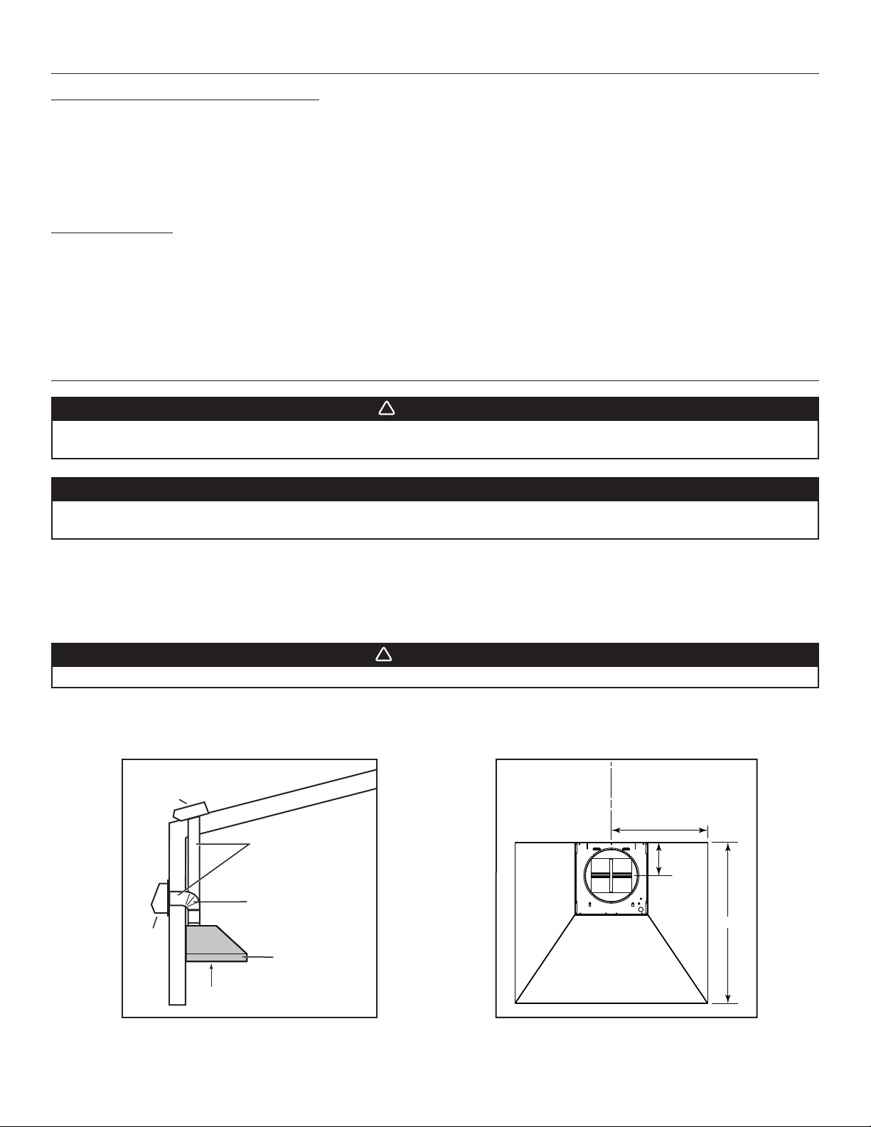
Plan where and how the ductwork will be installed. A straight, short duct run will allow the hood to perform most efficiently. Refer to
illustrations below to locate duct opening.
Install 10-inch ductwork, elbows (if needed) and roof or wall cap. Connect metal ductwork to the cap and work back towards the hood
location. Use 2" metal foil duct tape to seal the joints.
WARNING
The power cable must be a GFCI protected branch circuit.
Run 3-wire power supply cable to installation location.
The hood must be installed at least 36’’ above the cooking surface.
C
ROOF CAP
10” ROUND DUCT
10” ROUND ELBOW
WALL
CAP
HOOD
L
17 15/16” (36” hood)
20 15/16” (42” hood)
23 15/16” (48” hood)
6 1/4”
30”
HH0275A
36” ABOVE COOKING SURFACE
HK0282A
3
Page 4
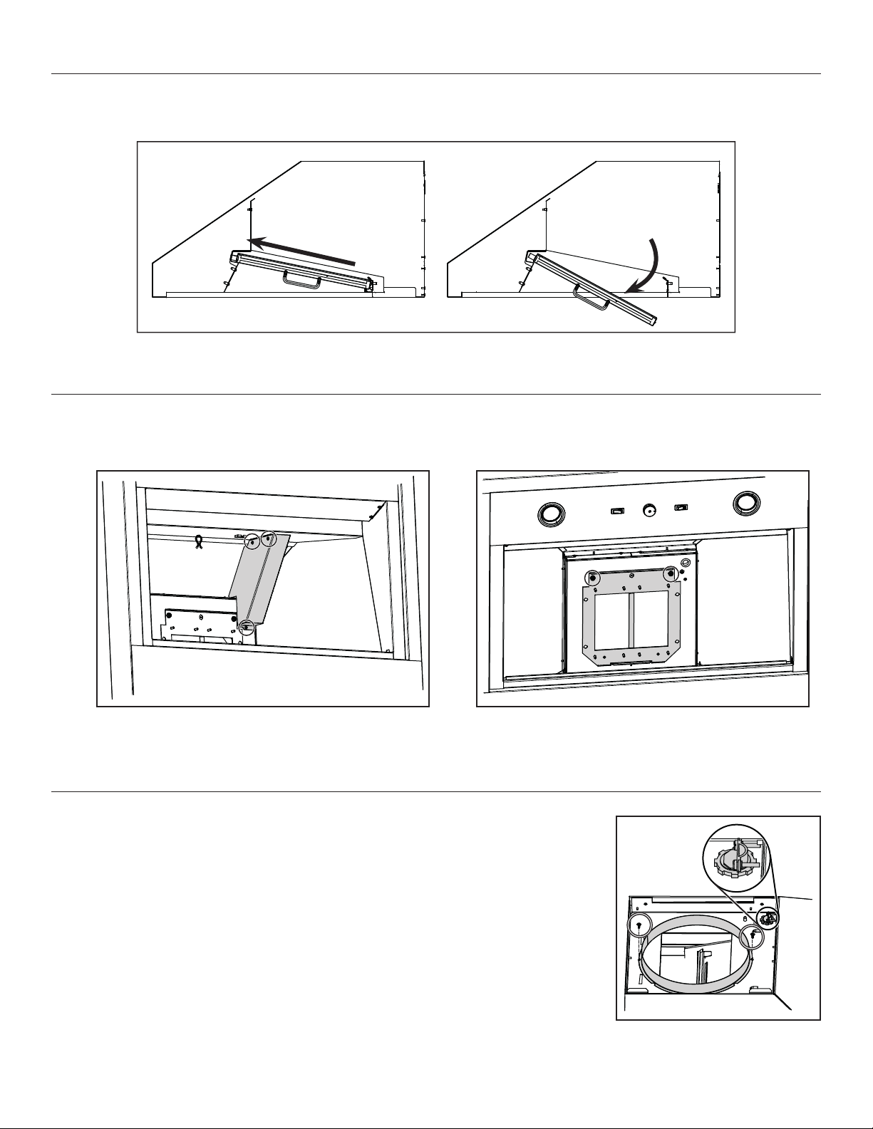
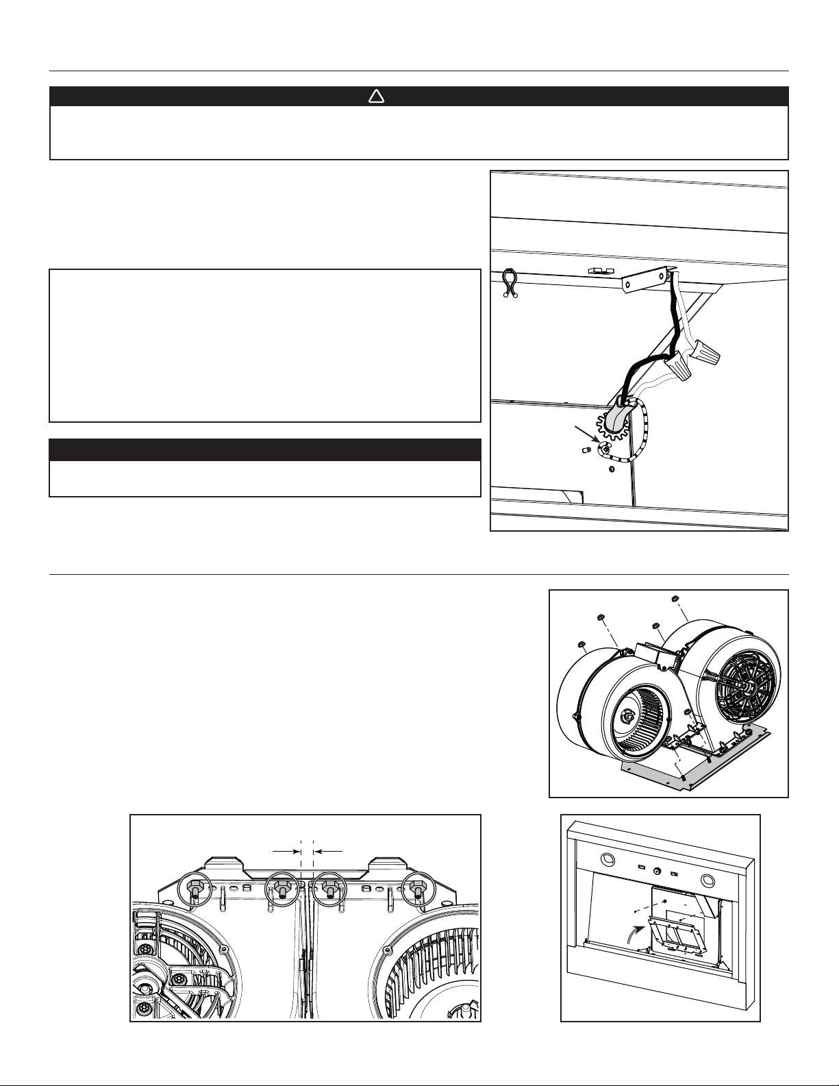
3. REMOVE THE GREASE FILTERS
Rest the range hood on a protected surface and remove the tape from the filters. Remove the filters from the range hood by pushing them
towards the nose of the hood and rotate downwards. Remove the parts bag, the adapter ring and the hood mounting bracket from inside
the hood and set these parts aside.
HD1079
4. REMOVE THE WIRING COVER AND THE BLOWER PLATE
Using a Philips no. 2 screwdriver, remove the 3 retaining
screws (circled in illustration below) holding the wiring
cover inside the hood. Set aside the cover and its screws.
HD1085
5. INSTALL THE ADAPTER AND THE WIRE CLAMP
Using a 3/8” nutdriver, remove 2 nuts retaining the blower
plate to the inner top of the hood, set the plate and nuts
aside.
HD1086
Install the 10-inch round adapter on the top of the hood using 2 no. 8-18 x 3/8” Phillips screws.
NOTE: Use the smaller notches around the adapter.
Install the wire clamp (as shown in the inset on illustration at right).
4
HJ0186
Page 5
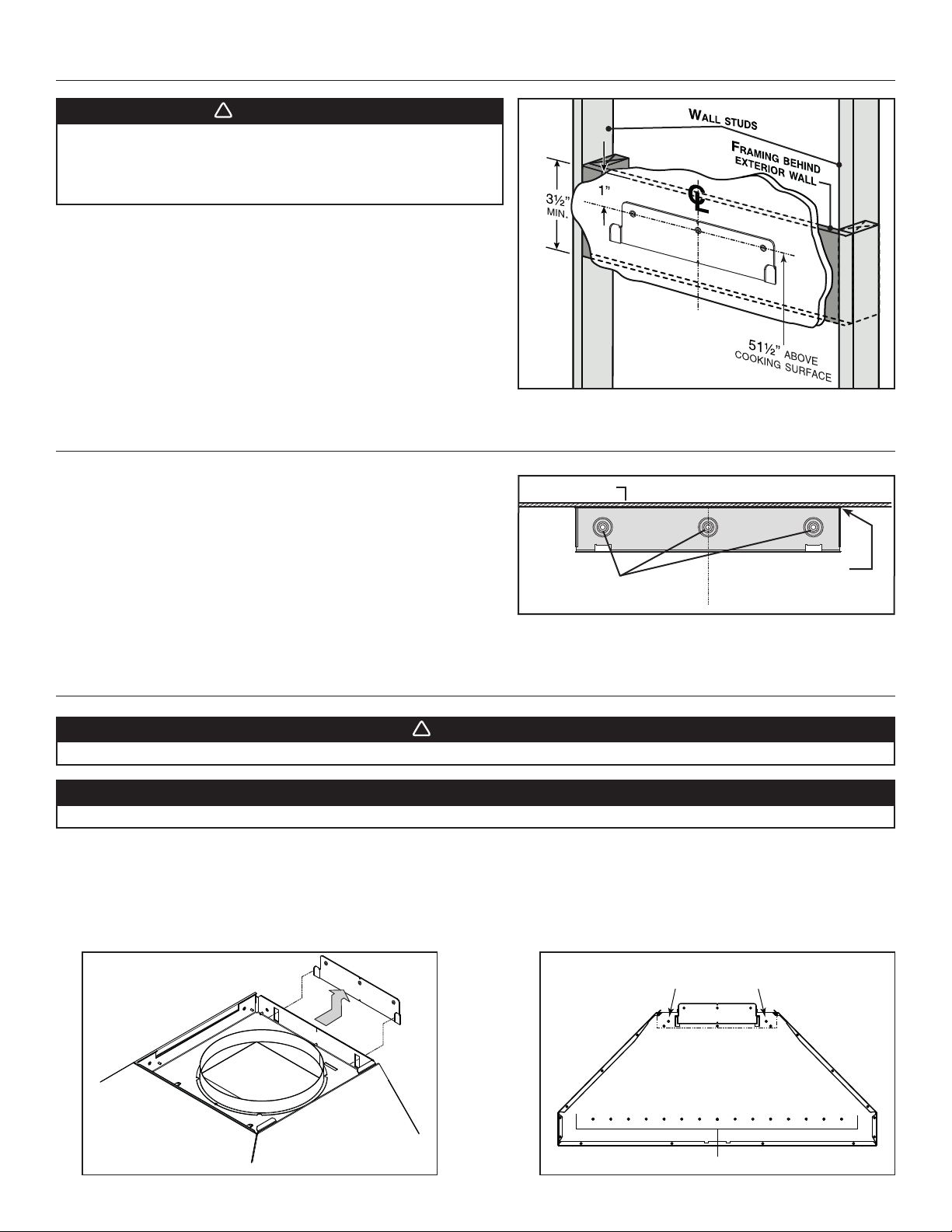
6. INSTALL HOOD MOUNTING BRACKET
!
HD0377
C
L
!
WARNING
When cutting or drilling into wall, do not damage electrical
wiring and other hidden utilities.
Ensure that the wall is solid enough to withstand the weight
of the hood.
If necessary, construct a wall framing using minimum 2” x 4” lumber. Proper
structural support is required to accomodate the weight of the hood.
After the wall surface is finished, measure and mark the center of the
installation; draw the vertical center line up to the ceiling.
Carefully center and level the hood mounting bracket over the installation
location. Secure it to the wall framing using 3 no. 10-12 x 2½” screws.
7. INSTALL UPPER FLUE MOUNTING BRACKET
HD1083A
NOTE: The upper flue mounting bracket is packed with the decorative
flue, but the mounting bracket screws are in the parts bag of
the hood.
Center the upper flue mounting bracket with the center line drawn in the
previous step and place it flush with the ceiling.
Use the upper flue mounting bracket as a template to mark the position of
the screws.
Secure the upper flue bracket to the wall using 3 no. 10-12 x 2½” screws.
Ensure that the bracket is tight against the wall.
CEILING
SCREW LOCATIONS
MOUNTING BRACKET
FLUSH WITH CEILING
8. INSTALL THE HOOD
WARNING
BE CAREFUL when installing the decorative flue and hood, they may have sharp edges.
CAUTION
DO NOT REMOVE the protective plastic film covering the decorative flue (upper & lower) yet.
1. Align the hood and center it above the hood mounting bracket. Gently lower the hood until it securely engages the bracket.
2. Level the hood.
3. While the hood is hanging in place, secure it to the wall through both holes located in the upper back of hood
using 2 no. 10-12 x 2½” screws and washers. If required, pre-drill holes before securing the screws.
4. Using at least 1 hole on each side of the lower back of the hood, secure the hood into solid material (wall studs)
using 2 no. 10-12 x 2½” screws and washers. If required, pre-drill holes before securing the screws.
RANGE HOOD BACK VIEW
UPPER HOLES LOCATION
HD1087
HD1084A
LOWER HOLES LOCATION
5
Page 6
!
9. CONNECT THE WIRING
WARNING
Risk of electric shock. Electrical wiring must be done by qualified personnel in accordance with all applicable
codes and standards. Before connecting wires, switch power off at service panel and lock service disconnecting
means to prevent power from being switched on accidentally.
Insert the house wiring cable through the wire clamp, and tighten the wire clamp
to secure the cable. Connect the power cable to the range hood wires using
provided waterproof wire connectors. Connect BLACK to BLACK, WHITE to
WHITE and GREEN or bare wire under GREEN ground screw. DO NOT FORGET
TO CONNECT THE GROUND.
WATERPROOF WIRE CONNECTORS INSTRUCTIONS:
1. Strip wires 3/8".
2. Align frayed strands or conductors.
3. Do not pre-twist. Place stripped wires together with ends even, but lead
smaller stranded wires slightly ahead of larger solid or stranded wire.
4. Twist connector onto wires pushing firmly until hand-tight. DO NOT over
torque.
5. When inserting wires into connectors, some sealant may leak out. Wipe off
excess sealant in and around conductors. DO NOT REUSE.
CAUTION
When reinstalling the wiring box cover, carefully insert the screws
by hand, then use a screwdriver to prevent stripping.
GROUND SCREW
Reinstall wiring box cover, making sure not to pinch wires.
HE0338
10. INSTALL THE BLOWER IN THE HOOD
Take the blower plate previously removed in step 4 and lay it on a protected surface.
Mount both blowers on the blower plate using 8 hexagonal nuts included with the blowers
(see illustration A). Make sure that both holes in the blower plate are entirely covered by the
blowers. The blowers should be 0.5 inch apart (see illustration B).
Reinstall the blower plate with blowers inside the hood by insert the blower plate tabs into
the slots and secure using both nuts previously removed in step 4 (see illustration C; blowers
not shown to ease understanding). Connect the blower power cord to the hood, and tie the
blower power cord using the preinstalled twist tie.
B C
0.5"
C
A
HO0343
HD1068A
HD1075
6
Page 7
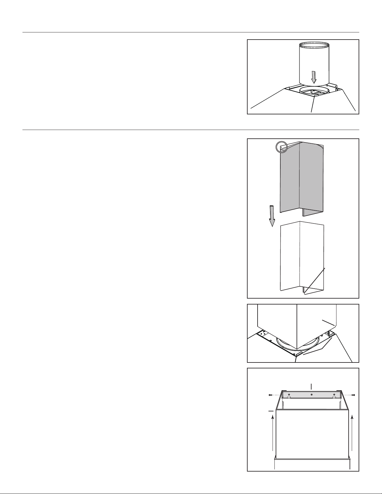
11. DUCT CONNECTION
Slide a 10” metal round duct over the adapter ring on top of the hood. Use metal foil duct
tape to seal the joint.
12. PREPARE AND INSTALL THE DECORATIVE FLUE
Remove the protective plastic film covering the lower flue only.
Peel off both corners at the top of the upper flue.
Position the lower flue rear notches down (the ones with the 45° angle).
Gently slide the upper flue inside the lower flue, making sure the holes are on the top, so
the upper flue can be screwed to the flue mounting bracket.
HJ0187
Carefully slide in place the decorative flues (notches end first) between the shaded parts
and the exterior wall of the top of the hood.
Slide up the upper flue until it is aligned with its mounting bracket. The bracket must be
inside the flue. Secure it to the bracket using 2 no. 8 x 3/8” screws (from hood parts bag).
NOTE: Duct not shown in illustration to ease understanding.
Remove the protective plastic film covering the upper flue.
HO0342
UPPER
FLUE
LOWER FLUE
REAR NOTCH
HO0341
LOWER FLUE
REAR NOTCH
SHADED
PA RT S
UPPER FLUE MOUNTING BRACKET
FRONT VIEW
HO0140
7
Page 8
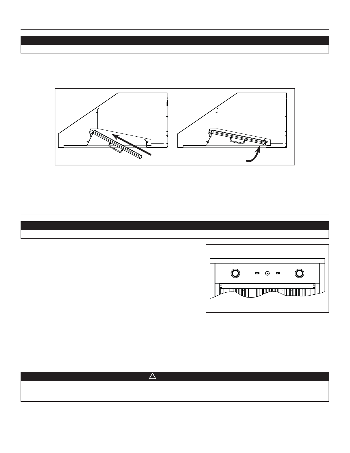
13. REINSTALL THE FILTERS
!
CAUTION
Remove the protective plastic film covering the filters before installing them.
It is recommended to install side filters first and to finish with center one(s).
1. Insert the end of the filter with the spring into the front channel of the hood.
2. Raise the other end toward the inside of the hood and insert in the grease drip rail.
HD1078
14. OPERATION
CAUTION
Before using the range hood, remove the remaining protective plastic film covering the hood surfaces.
BLOWER
The blower is operated using two controls.
Use the ON/OFF rocker switch (1) to start and stop the blower. When turned ON,
the switch turns red and the blower operates at the speed set by the speed control
knob (2).
Turn the speed control knob counterclockwise to increase blower speed – clockwise
to decrease speed.
COOKTOP LIGHTING (HALOGEN)
Use the ON/OFF rocker switch (3) to turn the halogen lights ON or OFF.
HEAT SENTRY™
This hood is equipped with a Heat Sentry™ thermostat. This thermostat is a device that will turn on the blower to high speed if it senses
excessive heat above the cooking surface.
1) If blower is OFF - it turns blower ON to high speed.
2) If blower is already ON - it sets blower on high speed.
HC0087
1) ON/OFF blower switch
2) Blower speed control knob
3) Halogen light switch
123
WARNING
The HEAT SENTRY can start the blower during a range top fire or other excessive heat situations even if the hood
is turned off. In this case, it is impossible to turn the blower OFF using control panel switch. To stop the blower, do
it from the main electrical panel.
When the temperature drops to normal, the blower will return to its original setting.
8
Page 9
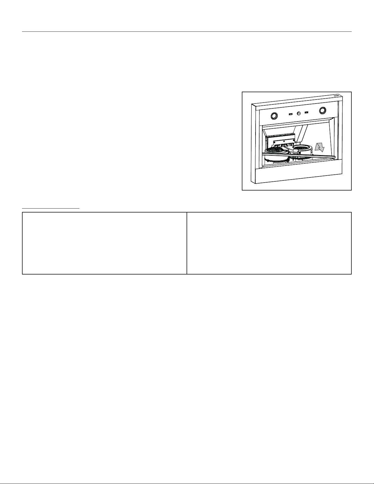
15. USE AND CARE
Baffle Filters
The baffle filters should be cleaned frequently. Use a warm detergent solution. Wash more often if your cooking style generates greater
grease — like frying foods or wok cooking.
Remove the filters from the range hood by pushing them towards the nose of the hood and rotate downwards. Baffle filters are dishwasher
safe. Allow filters to dry completely before reinstalling them in the hood.
Clean all-metal filters in the dishwasher using a non-phosphate detergent. Discoloration of the filters may occur if using phosphate
detergent or as a result of local water conditions — but this will not affect filter performance. This discoloration is not covered by the
warranty.
Grease Drip Rail
The grease drip rail should be cleaned frequently. To remove, rotate the grease rail to
disengage it from the bottom panel, then slide it away in a diagonal movement. Wash in a
a warm detergent solution. As with the baffle filters, wash more often if your cooking style
generates greater grease — like frying foods or wok cooking. Allow the grease drip rail to
dry completely before reinstalling it in the hood.
HD1088
General cleaning instructions
Stainless steel cleaning:
Do:
• Regularly wash with clean cloth or rag soaked with warm water
and mild soap or liquid dish detergent.
• Always clean in the direction of original polish lines.
• Always rinse well with clear water (2 or 3 times) after cleaning.
Wipe dry completely.
• You may also use a specialized household stainless steel
cleaner.
Don’t:
• Use any steel or stainless steel wool or any other scrapers to
remove stubborn dirt.
• Use any harsh or abrasive cleansers.
• Allow dirt to accumulate.
• Let plaster dust or any other construction residues reach the
range hood. During construction/renovation, cover the range
hood to make sure no dust sticks to stainless steel surface.
Avoid when choosing a detergent:
- Any cleaners that contain bleach will attack stainless steel.
- Any products containing: chloride, fluoride, iodide, bromide will deteriorate surfaces rapidly.
- Any combustible products used for cleaning such as acetone, alcohol, ether, benzol, etc., are highly explosive and should never be
used close to a range.
9
Page 10

!
16. LIGHT BULBS REPLACEMENT
!
This hood is equiped with two 120 V, 50 W, MR16 with GU10 base, shielded halogen bulbs.
WARNING
Do not touch lamps during or soon after operation. Burns may occur. In order to prevent the risk of personal injury,
only install shielded halogen lamps. Also, never install a cool beam, a dichroic lamp, a lamp not suitable for use in
recessed luminaires or identified for use in enclosed fixtures.
To remove the bulbs, press suction cup tool (included in parts bag) on bulb and rotate counterclockwise to disengage the bulb leads from
their grooves.
Install the new bulbs by placing the bulb leads into their grooves in the socket.
Gently push upwards and turn clockwise until secure.
SUCTION CUP TOOL
BULB LEADS
HR0212
BULB LEAD GROOVES
(IN SOCKET)
17. WIRING DIAGRAM
WARNING
Risk of electrical shock. Electrical wiring must be done by qualified personnel in accordance with all applicable
codes and standards. Before connecting wires, switch power off at service panel and lock service disconnecting
means to prevent power from being switched on accidentally.
HS
THERMO STAT
SPEED CONTROL
BLK
RED
Lamp
Line
Neutral
Ground
120 V AC
WHT
BLK
RED
BLK
COLOR CODE
BLACK
RED
BLK
WHT
WHT
WHITE
YEL
YELLOW
REF: 70103_REV-B
WHT
BLK
C
M
WHT
YEL
Fan switch
BLK
WHT
WHT
Lamp switch
RED
BLK
WHT
YEL
YEL
Lamp
C
BLK
WHT
HE0346A
M
10
Page 11

18. SERVICE PARTS
B
C
REPLACEMENT PARTS AND REPAIRS
In order to ensure your unit remains in good working
condition, you must use Broan-NuTone genuine
replacement parts only. Broan-NuTone genuine
replacement parts are specially designed for each unit
and are manufactured to comply with all the applicable
certification standards and maintain a high standard of
safety. Any third party replacement part used may cause
serious damage and drastically reduce the performance
level of your unit, which will result in premature failing.
Broan-NuTone recommends to contact a certified service
depot for all replacement parts and repairs.
D
E
N
M
L
F
G
K
H
I
J
HL0432
KEY NO.PART NO.DESCRIPTION
1 AEWTD915SB* D
1 AEWTD1629SB* DECORATIVE FLUE KIT - 8.5 TO 9.5-FT HIGH CEILING 111
1 AEWTD3057SB* DECORATIVE FLUE KIT - 9.5 TO 12-FT HIGH CEILING 111
2 SV08541 10” ROUND ADAPTER 111
3 SV16569 LIGHT SOCKET AND TRIM ASSEMBLY 222
4 SV05921 GU10 HALOGEN BULB 222
5 SV03435 HEAT SENTRY™ THERMOSTAT 111
6 SV02563 L
7 P12NA** BLOWER ASSEMBLY 111
8
9 SV08337 S
10
11 SV03503 BLOWER ROCKER SWITCH 111
12 SV08549 BLOWER SPEED CONTROL KNOB 111
13 SV03501 BLOWER SPEED CONTROL 111
*** SV23320
* OPTIONAL PAR T , SOLD SEPARATELY
** PART SOLD SEPARATELY
*** NOT SHOWN
SV60675 BAFFLE FILTER WITH FILTER SPRING 11.84” X 15.125” 1 3 2
SV60716 B
SV65734 G
SV65735 GREASE RAIL FOR 42-IN.-WIDE HOOD 010
SV65736 G
ECORATIVE FLUE KIT - 8 TO 8.5-FT HIGH CEILING 111
IGHT ROCKER SWITCH 111
AFFLE FILTER WITH FILTER SPRING 8.84” X 15.125” 2 0 2
PRINGS FOR BAFFLE FILTERS (SET OF 6) 1 1 1
REASE RAIL FOR 36-IN.-WIDE HOOD 100
REASE RAIL FOR 48-IN.-WIDE HOOD 001
PARTS BAG: 1 WIRE CLAMP, 3 WATERPROOF WIRE CONNECTORS,
14 NO. 10-12 X 2½” SCREWS, 4 NO. 8-18 X 3/8” SCREWS, 10WASHERS, 1SUCTION CUP.
QUANTITY
36" 42" 48"
111
11
Page 12

19. WARRANTY
FIVE-YEAR LIMITED WARRANTY FOR BEST® PRODUCTS
Warranty Period and Exclusions: Broan-NuTone, LLC (the “Company”) warrants to the consumer purchaser of its product (“you”) that the product (the
“Product”) will be free from material defects in the materials or its workmanship for a period of five (5) years from the date of original purchase (or such
longer period as may be required by applicable law) or a period of two (2) years from the date of service for any labor provided on the Product.
The limited warranty period for any replacement parts provided by the Company and for any Products repaired or replaced under this limited warranty shall
be the remainder of the original warranty period (or such longer period as may be required by applicable law).
THIS WARRANTY DOES NOT EXTEND TO FLUORESCENT LAMP STARTERS, TUBES AND BULBS, FUSES, FILTERS, DUCTS, ROOF CAPS, WALL CAPS
AND OTHER ACCESSORIES FOR DUCTING. This warranty does not cover (a) normal maintenance and service, (b) normal wear and tear, (c) any Products or
parts which have been subject to misuse, abuse, abnormal usage, negligence, accident, improper or insufficient maintenance, storage or repair (other than
repair by the Company), (d) damage caused by faulty installation, or installation or use contrary to recommendations or instructions, (f) damage caused by
exposure to salt air, (g) damage in transit, (h) natural wear of finish, (i) Products in commercial or nonresidential use, (j) damage caused by fire, flood or
other act of God, or (k) Products with altered, defaced or removed serial numbers. This warranty covers only Products sold to consumers in North America.
This warranty supersedes all prior warranties and, subject to applicable law, is not transferable from the original consumer purchaser.
No Other Warranties: This Limited Warranty contains the Company’s sole obligation and your sole remedy for defective Products. The foregoing warranties
are exclusive and in lieu of any other warranties and conditions, express or implied. TO THE MAXIMUM EXTENT PERMITTED BY APPLICABLE LAW, THE
COMPANY DISCLAIMS AND EXCLUDES ALL OTHER EXPRESS WARRANTIES AND CONDITIONS, AND DISCLAIMS AND EXCLUDES ALL WARRANTIES
AND CONDITIONS IMPLIED BY LAW, INCLUDING WITHOUT LIMITATION THOSE OF MERCHANTABILITY AND FITNESS FOR A PARTICULAR PURPOSE.
To the extent that applicable law prohibits the exclusion of implied warranties or conditions, the duration of any applicable implied warranty or condition
is limited to the period specified for the express warranty above. Some jurisdictions (which may include the Province of Quebec or specific US states) do
not allow limitations on how long an implied warranty lasts, so the above limitation may not apply to you. Any oral or written description of the Product is
for the sole purpose of identifying it and shall not be construed as an express warranty.
Whenever possible, each provision of this Limited Warranty shall be interpreted in such manner as to be effective and valid under applicable law, but if any
provision is held to be prohibited or invalid, such provision shall be ineffective only to the extent of such prohibition or invalidity, without invalidating the
remainder of such provision or the other remaining provisions of the Limited Warranty.
Remedy: During the applicable limited warranty period, the Company will, at its option, provide replacement parts for, or repair or replace, without charge,
any Product or part thereof, to the extent the Company finds it to be covered by and in breach of this limited warranty under normal use and service. The
Company will ship the repaired or replaced Product or replacement parts to you at no charge. You are responsible for all costs for removal, reinstallation
and shipping, insurance or other freight charges incurred in the shipment of the Product or part to the Company. If you must send the Product or part
to the Company, as instructed by the Company, you must properly pack the Product or part—the Company is not responsible for damage in transit. The
Company reserves the right to utilize reconditioned, refurbished, repaired or remanufactured Products or parts in the warranty repair or replacement
process. Such Products and parts will be comparable in function and performance to an original Product or part and warranted for the remainder of the
original warranty period (or such longer period as may be required by applicable law).
Company reserves the right, in its sole discretion, to refund the money actually paid by you for the Product. If the Product or component is no longer
available, replacement may be made with a similar product of equal or greater value, at Company’s sole discretion. This is your sole and exclusive remedy
for breach of this limited warranty.
Exclusion of Damages: THE COMPANY’S OBLIGATION TO PROVIDE REPLACEMENT PARTS, OR REPAIR OR REPLACE, AT THE COMPANY’S OPTION,
SHALL BE YOUR SOLE AND EXCLUSIVE REMEDY UNDER THIS LIMITED WARRANTY AND THE COMPANY’S SOLE AND EXCLUSIVE OBLIGATION. THE
COMPANY SHALL NOT BE LIABLE FOR INCIDENTAL, INDIRECT, CONSEQUENTIAL OR SPECIAL DAMAGES ARISING OUT OF OR IN CONNECTION WITH
THE PRODUCT, ITS USE OR PERFORMANCE.
Some jurisdictions do not allow the exclusion or limitation of incidental or consequential damages, so the above limitation or exclusion may not apply
to you. This warranty gives you specific legal rights, and you may also have other rights, which vary from jurisdiction to jurisdiction. The disclaimers,
exclusions, and limitations of liability under this warranty will not apply to the extent prohibited by applicable law.
This warranty covers only replacement or repair of defective Products or parts thereof at the Company’s main facility and does not include the cost of field
service travel and living expenses.
Any assistance the Company provides to or procures for you outside the terms, limitations or exclusions of this limited warranty will not constitute a waiver
of such terms, limitations or exclusions, nor will such assistance extend or revive the warranty. The Company will not reimburse you for any expenses
incurred by you in repairing or replacing any defective Product, except for those incurred with the Company’s prior written permission.
How to Obtain Warranty Service: To qualify for warranty service, you must (a) notify the Company at the address or telephone number stated below within
seven (7) days of discovering the covered defect, (b) give the model number and part identification and (c) describe the nature of any defect in the Product
or part. At the time of requesting warranty service, you must present evidence of the original purchase date. If you cannot provide a copy of the original
written limited warranty, then the terms of the Company’s most current written limited warranty for your particular product will control.
PRODUCT SPECIFICATIONS
All illustrations and specifications in this catalog are based on the latest product information available at time of production. Broan-NuTone, LLC and
BEST® reserves the right to make changes at any time, without notice, in prices, colors, materials, equipment, specifications and models, place of
manufacture and to discontinue models or equipment.
Best
Broan-NuTone, LLC- 926 W. State Street, Hartford, WI 53207 1-800-637-1453
Best®, 550 Lemire Blvd., Drummondville, QC, Canada (1-866-737-7770) www.bestrangehoods.com
12
Page 13
INSTRUCCIONES DE INSTALACIÓN
HB0305
SERIE WTD9M
! !
EXCLUSIVAMENTE PARA COCINAS DOMÉSTICAS EXTERIORES
LEA ESTAS INSTRUCCIONES Y GUÁRDELAS
INSTALADOR: ENTREGUE ESTE MANUAL AL PROPIETARIO DE LA CASA.
PROPIETARIO: INFORMACIÓN SOBRE UTILIZACIÓN Y CUIDADO
EN LAS PÁGINAS 8 Y 9.
BEST; Hartford, Wisconsin www.BestRangeHoods.com 800-558-1711
BEST; Drummondville, QC, Canada www.BestRangeHoods.ca 866-737-7770
Para registrar su producto en línea o para obtener más información, visitar nuestro sitio www.BestRangeHoods.com
23644 rev. 02
Page 14

!
ADVERTENCIA
!
ADVERTENCIA
PARA REDUCIR EL RIESGO DE INCENDIO, DESCARGA
ELÉCTRICA O LESIÓN CORPORAL, RESPETE LAS
SIGUIENTES INDICACIONES:
1. Utilice esta unidad únicamente de la forma en que indica el
fabricante. Si tiene cualquier pregunta, póngase en contacto
con el fabricante en la dirección o el teléfono que aparecen en
la garantía.
2. Antes de reparar o limpiar el aparato, apáguelo en el tablero
de servicio y bloquee los medios de desconexión para impedir
que la corriente se conecte accidentalmente. Cuando no se
pueda bloquear los medios de desconexión, coloque un
dispositivo de advertencia visible (como una etiqueta) en el
tablero de servicio.
3. La instalación y la conexión eléctrica deben ser realizadas
por personal calificado de acuerdo con todos los códigos
y normas aplicables, incluso los relativos a la construcción
ignífuga.
4. Para lograr una combustión adecuada y una extracción correcta
de los gases a través de la salida del humo (chimenea) del
equipo quemador de combustible — evitando así el contratiro
— es necesario disponer de aire suficiente. Siga las directrices
del fabricante del equipo de material térmico y las normas
de seguridad, como las que publica la NFPA (asociación
de protección contra los incendios) y la ASHRAE (sociedad
estadounidense de técnicos de calefacción, refrigeración y
aire acondicionado) así como los códigos de los organismos
responsables locales.
5. Al cortar o perforar la pared o el techo, procure no dañar el
cableado eléctrico ni otras instalaciones de servicios públicos.
6. Los ventiladores entubados siempre deben tener salida al
exterior.
7. No utilice este aparato con un dispositivo de control de
velocidad con semiconductores.
8. Para reducir el riesgo de incendio, utilice sólo tuberías
metálicas.
9. Este aparato debe conectarse a tierra y ha de estar protegido
con un disyuntor.
10. Adecuado para lugares húmedos cuando se instala en un
circuito de derivación PROTEGIDO CON UN DISYUNTOR.
11. Este aparato no está pensado para utilizarse con una parrilla
de carbón.
12. Cuando une reglamentación local esta en vigor y conlleva
exigencias de instalación y/o de certificación mas estrictas,
susodichas exigencias prevalecen sobre aquellas en
este documento y el instalador acepta someterse a estas
exigencias a sus gastos.
PARA REDUCIR EL RIESGO DE QUE ARDA LA GRASA
EN LA PARTE SUPERIOR DE LA COCINA:
a) No deje nunca recipientes de cocina a fuego vivo sin vigilancia.
Los desbordamientos producen humo y derrames grasientos
que pueden inflamarse. Caliente el aceite despacio, a fuego
lento o mediano.
b) Ponga en marcha siempre la campana extractora al cocinar
a temperaturas elevadas o al cocinar alimentos flameados
(crepas Suzette, cerezas jubilee, res con pimienta flambeada).
c) Limpie los ventiladores con frecuencia. No deje que la grasa
se acumule en el ventilador, ni en los filtros o en los conductos
de evacuación.
d) Utilice cacerolas de tamaño apropiado. Emplee siempre un
recipiente adecuado para el tamaño de la placa.
PARA REDUCIR EL RIESGO DE LESIONES
CORPORALES EN EL CASO DE QUE ARDA LA GRASA
EN LA PARTE SUPERIOR DE LA COCINA, SIGA ESTAS
INDICACIONES*:
1. SOFOQUE LAS LLAMAS con una tapa ajustada, una hoja
o bandeja metálica para hornear galletas, y apague luego el
quemador. TENGA CUIDADO PARA EVITAR QUEMADURAS.
SI LAS LLAMAS NO SE APAGAN INMEDIATAMENTE,
EVACUE EL LUGAR Y LLAME A LOS BOMBEROS.
2. NO SUJETE NUNCA UNA SARTÉN EN LLAMAS ya que
podría quemarse.
3. NO USE AGUA, ni trapos húmedos. Podría causar una
violenta explosión de vapor.
4. Utilice un extintor SOLAMENTE si:
A. Tiene un extintor de tipo ABC y sabe usarlo.
B. El incendio es pequeño y está circunscrito a la zona donde
empezó.
C. Ya ha llamado a los bomberos.
D. Puede tratar de apagar el fuego si dispone siempre de
una salida detrás de usted.
* Fuente: “Kitchen Fire Safety Tips” publicado por la NFPA
PRECAUCIÓN
1. Sólo para ventilación general. No debe utilizarse para extraer
materiales o vapores peligrosos o explosivos.
2. Para evitar daños en el cojinete de los motores y que las hélices
haga ruido o se desequilibre, mantenga la campana lejos de
los vaporizadores de pirca, del polvo de la construcción, etc.
3. El motor de la campana tiene un dispositivo contra sobrecargas
térmicas que apaga el motor automáticamente si éste se
sobrecalienta. El motor volverá a ponerse en marcha cuando
se enfríe. Si el motor sigue apagándose, haga examinar la
campana.
4. Para que la campana capte bien las impurezas que se
desprenden al cocinar, la distancia mínima entre la campana
y la superficie de la cocina debe ser a 36 pulgadas.
5. Dado el peso y el tamaño de esta unidad, se aconseja que la
instalen dos personas.
6. Para reducir los riesgos de incendio y extraer el aire
debidamente, el aire debe evacuarse fuera. No extraiga el aire
a espacios situados entre las paredes, en el techo o en el
desván, falso techo o garaje.
7. Este producto está equipado con un termostato que puede
poner en marcha el ventilador automáticamente. Para reducir
el riesgo de que se produzcan daños y evitar poner en marcha
la alimentación accidentalmente, apague la corriente en el
tablero de servicio, bloquee este tablero o ponga una etiqueta
de advertencia.
8. Para reducir el riesgo de incendio y de choque eléctrico,
los modelos de la serie WTD9M de Best deben instalarse
únicamente con el ventilador P12NA (se vende aparte). No
emplee otros ventiladores.
9. Para mayor información y conocer los requisitos, lea la
etiqueta con las especificaciones en el producto.
2
Page 15

1. PREPARACIÓN DE LA INSTALACIÓN
!
!
NOTA: Antes de comenzar la instalación, verificar el contenido de la caja. Si alguna pieza falta o está dañada, póngase en contacto con
el fabricante.
Compruebe que el conjunto para la instalación contiene los elementos siguientes:
- Campana
- Accesorios • Soporte de montaje de la campana (retenido con cinta adhesiva en el interior de la campana)
• Adaptador redondo de 10 pulgadas (retenido con cinta adhesiva en el interior de la campana)
• Manual de instalación
• Bolsa de piezas que incluye: 3 conectores impermeables de hilos, 1 abrazadera para hilos,
14 tornillos n.° 10-12 x 2½”, 4 tornillos n.° 8-18 x 3/8”, 10 arandelas, 1ventosa (incluye más piezas que necesarias
para la instalación) (la bolsa esta retenida con cinta adhesiva en el interior de la campana).
Piezas vendidas por separado:
- Ventilador P12NA
- Conducto decortiva :
- Pieza n.° AEWTD915SB para un techo de 8 pies a 8.5 pies de altura
- Pieza n.° AEWTD1629SB para un techo de 8,5 pies a 9,5 pies de altura
- Pieza n.° AEWTD3057SB para un techo de 9,5 pies a 12 pies de altura.
2. INSTALAR LOS CONDUCTOS Y EL CABLEADO ELÉCTRICO
ADVERTENCIA
Se aconseja llevar lentes y guantes de seguridad para instalar, reparar o limpiar la campana. Este campana no es
diseñada por una utilizacíon con un parilla de carbón.
PRECAUCIÓN
Este campana está prevista para patios o terrazas exteriores cubiertos. Como ocurre con todos los aparatos
eléctricos, se debe proteger esta campana todo lo posible de la intemperie.
Estas campanas deben instalarse con el ventilador P12NA (se vende aparte). No lo sustituya por otro ventilador.
Planifique dónde y cómo instalará los conductos. Un conducto recto y corto hará que la campana funcione más eficientemente. Consulte
las ilustraciones que aparecen a continuación para localizar la abertura del conducto.
Instale conductos, codos (si es necesario) y el capuchón de la pared o del tejado de 10 pulgadas. Empiece conectando el conducto de
metal al capuchón y prosiga hacia el lugar donde se encuentre la campana. Utilice cinta adhesiva metálica de 2 pulgadas para sellar las
juntas.
ADVERTENCIA
El cable de alimentación debe ser un circuito de derivación protegido con un disyuntor.
Lleve un cable de alimentación de tres hilos hasta el lugar de la instalación.
La distancia mínima entre la campana y la superficie sobre la que se cocina no debe ser inferior a 36 pulgadas.
C
CAPUCHÓN DE TEJADO
CONDUCTO
REDONDO
DE 10”
L
17 15/16” (campana de 36”)
20 15/16” (campana de 42”)
23 15/16” (campana de 48”)
6 1/4”
CODO REDONDO
CAPUCHÓN
MURAL
HH0275E
DE 10”
HOTTE
36” POR ENCIMA DE LA
SUPERFICIE DE LA COCINA
HK0282E
30”
3
Page 16

3. QUITE LOS FILTROS DE GRASA
Ponga la campana sobre una superficie protegida y retire la cinta de los filtros. Quite los filtros de la campana empujándolos hacia la parte
delantera de la campana y girándolos hacia abajo. Saque la bolsa de piezas, el anillo adaptador y el soporte de montaje de la campana
desde el interior de la campana y ponga a un lado estas piezas.
HD1079
4. RETIRE LA TAPA DEL CABLEADO Y LA PLACA DEL VENTILADOR
Utilice un destornillador Phillips n.° para quitar los 3 tornillos
de retención (rodeados con un círculo en la ilustración abajo)
que sujetan la tapa del cableado dentro de la campana.
Ponga a un lado la tapa y sus tornillos.
HD1085
Utilice una llave para tuercas de 3/8" para retirar las 2 tuercas
que sujetan la placa del ventilador al interior de la parte
superior de la campana; ponga a un lado la placa y las
tuercas.
HD1086
5. INSTALE EL ADAPTADOR Y LA ABRAZADERA DE HILOS
Instale el adaptador redondo de 10 pulgadas en la parte superior de la campana utilizando
2 tornillos Phillips n.° 8-18 x 3/8".
NOTA: Utilice las pequeñas muescas alrededor del adaptador.
Instale la abrazadera de hilos (como se muestra en el recuadro de la ilustración de la derecha).
4
HJ0186
Page 17

6. INSTALE EL SOPORTE DE MONTAJE DE LA CAMPANA
!
HD0377
C
L
!
ADVERTENCIA
Al cortar o taladrar en la pared, procure no dañar el cableado eléctrico ni otras instalaciones ocultas.
Asegúrese de que la pared es lo suficientemente sólida
como para soportar el peso de la campana.
Si es necesario, construya una estructura mural con madera de 2" x 4"
como mínimo. Se necesita un apoyo estructural adecuado para soportar
el peso de la campana.
Una vez acabada la superficie mural, mida y marque el centro de la
instalación; dibuje la línea vertical central hasta el techo.
Centre y ponga a nivel cuidadosamente el soporte de montaje de la
campana en el lugar de la instalación. Sujete el soporte de montaje a la
estructura mural con 3 tornillos n.° 10-12 x 2½”.
HD1083E
7. INSTALE EL SOPORTE DE MONTAJE DE LA PARTE SUPERIOR DE LA CHIMENEA
NOTA: El soporte de montaje de la parte superior de la chimenea
viene empaquetado con la chimenea decorativa, pero los
tornillos del soporte de montaje están en la bolsa de piezas
de la campana.
Centre el soporte de montaje de la parte superior de la chimenea con la
línea central trazada en la etapa anterior y colóquelo a ras con el techo.
Use el soporte de montaje de la parte superior de la chimenea como
plantilla para marcar la posición de sus tornillos.
Sujete el soporte de la parte superior de la chimenea con 3 tornillos
n.° 10-12 x 2½”.
Asegúrese de que el soporte quede bien apretado contra la pared.
TECHO
UBACACIÓN DE
TORNILLOS
LOS
SOPORTE DE MONTAJE
A RAS CON EL TECHO
8. INSTALE LA CAMPANA
ADVERTENCIA
TENGA CUIDADO al instalar la chimenea decorativa y la campana, pueden tener bordes cortantes.
PRECAUCIÓN
NO RETIRE aún la película protectora de plástico que cubre la chimenea decorativa (parte superior e inferior).
1. Alinee la campana y céntrela por encima del soporte de montaje de la campana. Baje suavemente la campana hasta que encaje
firmemente en el soporte.
2. Ponga a nivel la campana.
3. Aunque la campana esté colgada, sujétela a la pared a través de ambos orificios situados en la parte superior trasera de la campana
utilizando 2 tornillos n.° 10-12 x 2½" y arandelas. Si es necesario, taladre los orificios antes de fijar los tornillos.
4. Utilice al menos 1 orificio en cada lado de la parte inferior trasera de la campana para sujetar la campana a un material sólido
(montantes) usando para ello 2 tornillos n.° 10-12 x 2½" y arandelas. Si es necesario, taladre los orificios antes de fijar los tornillos.
VISTA DE LA PART E TRASERA DE LA CAMPANA
UBICACIÓN DE LOS ORIFICIOS SUPERIORES
HD1087
HD1084E
UBICACIÓN DE LOS ORIFICIOS INFERIORES
5
Page 18

9. CONEXIÓN DEL CABLEADO
!
ADVERTENCIA
Riesgo de choque eléctrico. La conexión eléctrica debe hacerla personal competente con arreglo a los códigos y
normas en vigor. Antes de conectar los hilos, corte la alimentación en el tablero de servicio y bloquee los medios
de desconexión para impedir que la corriente se conecte accidentalmente.
Introduzca el cable de conexión doméstico a través de la abrazadera para hilos
y apriete la abrazadera para sujetar el cable. Conecte el cable en la caja de
conexiones con los conectores impermeables de hilos incluidos. Conecte el hilo
NEGRO con el NEGRO, el BLANCO con el BLANCO y el VERDE o desnudo en
el tornillo de tierra VERDE. NO OLVIDE CONECTAR LA TIERRA.
INSTRUCCIONES PAR A LOS CONECTORES IMPERMEABLES DE HILOS:
1. Pele 3/8 de pulg. de los hilos.
2. Junte las puntas peladas o conductores.
3. No las retuerza. Coloque los hilos pelados juntos, con los extremos a la
misma altura. Si la parte pelada de uno de los hilos es más corta que la del
otro, ponga ese hilo más alto.
4. Gire el conector sobre los hilos empujando firmemente hasta que quede
bien apretado. NO apriete demasiado.
5. Al introducir los hilos en los conectores, puede que salgan restos de un
producto para la obturación. Limpie el sobrante de este producto alrededor
de los conductores. NO VUELVA A UTILIZAR LOS CONECTORES.
PRECAUCIÓN
Al volver a instalar la tapa de la caja de cableados, introduzca
con cuidado los tornillos con la mano y, a continuación, utilice un
destornillador para evitar daños a la rosca de los tornillos.
Vuelva a instalar la tapa de la caja de cableados asegurándose de no aplastar
los cables.
TORNILLO DE
TIERRA
HE0338
10. INSTALE EL VENTILADOR EN LA CAMPANA
Tome la placa del ventilador que retiró en la etapa 4 y colóquela sobre una superficie
protegida.
Monte ambos ventiladores en la placa del ventilador con 8 tuercas hexagonales que vienen
con los ventiladores asegurándose de que los ventiladores cubran totalmente ambos
agujeros en la placa del ventilador (véase la ilustración A). Entre los ventiladores debe
haber una separación de 0,5 pulgadas (véase la ilustración B).
Vuelva a instalar la placa del ventilador con los ventiladores en la campana introduciendo
las lengüetas de la placa en las ranuras y sujetándolas con las tuercas que retiró en la
etapa 4 (véase la ilustración C; los ventiladores no aparecen para facilitar la comprensión).
Conecte el cable de alimentación de los ventiladores a la campana y ate el cable de
alimentación de los ventiladores con el alambre preinstalado.
B C
0.5"
C
A
HO0343
HD1068A
HD1075
6
Page 19

11. CONEXIÓN DEL CONDUCTO
Ponga un conducto redondo de 10” sobre el adaptador en la campana. Utilice cinta
adhesiva metálica para sellar la junta.
12. PREPARE E INSTALE LA CHIMENEA DECORATIVA
Retire la película protectora de plástico que cubre sólo la parte inferior de la chimenea
decorativa.
Pele las dos esquinas en la parte superior de la chimenea decorativa.
Coloque hacia abajo las muescas traseras de la parte inferior de la chimenea decorativa
(que tienen un ángulo de 45°).
Deslice suavemente la parte superior de la chimenea decorativa dentro de la parte inferior
de la chimenea decorativa, asegurándose de que los orificios estén en la parte superior,
de modo que la parte superior de la chimenea decorativa pueda atornillarse al soporte de
montaje.
HJ0187
MUESCA
TRASERA DE
LA PA RT E
INFERIOR DE
LA CHIMENEA
HO0341
Coloque cuidadosamente en su lugar las dos partes de la chimenea decorativa (el extremo
con las muescas en primer lugar) entre la parte sombreada y la pared exterior de la parte
superior de la campana.
Deslice hacia arriba la parte superior de la chimenea hasta que quede alineada con
el soporte de montaje. El soporte debe quedar dentro de la chimenea. Sujete la parte
superior de la chimenea al soporte con 2 tornillos n.° 8 x 3/8" (incluidos en la bolsa de
piezas de la campana).
NOTA: no se muestra el conducto en la ilustración para facilitar la comprensión.
Retire la película protectora de plástico que cubre la parte superior de la chimenea.
7
MUESCA TRASERA
HO0342
SOPORTE DE MONTAJE DE LA PA RT E
SUPERIOR DE LA CHIMENEA
PARTE
SUPERIOR
DE LA
CHIMENEA
HO0140
PARTE
SOMBREADA
Page 20

13. VUELVA A INSTALAR LOS FILTROS
!
PRECAUCIÓN
Retire la película protectora de plástico que cubre los filtros antes de instalarlos.
Se aconseja instalar primero los filtros laterales y terminar por el o los centrales.
1. Introduzca el extremo del filtro con el muelle en el canal delantero de la campana.
2. Levante el otro extremo hacia el interior de la campana e introdúzcalo en el riel de vertido de la grasa.
HD1078
14. FUNCIONAMIENTO
PRECAUCIÓN
Antes de utilizar la campana, retire la película protectora de plástico restante que cubre la superficie de la campana.
VENTILADOR
El ventilador se maneja con dos controles.
Utilice el interruptor oscilante (1) para poner en marcha y detener el ventilador. Al
ponerlo en marcha, el interruptor se ilumina en rojo y el ventilador funciona a la
velocidad que se haya elegido con el botón de control de velocidad (2).
Gire el botón de control de velocidad en el sentido contrario de las agujas del reloj
para incrementar la velocidad del ventilador y en el sentido de las agujas del reloj
para disminuirla.
LUCES (HALÓGENAS)
Utilice el interruptor oscilante (3) para encender y apagar las luces halógenas.
HEAT SENTRY™
Este campana viene equipado con un termostato Heat Sentry™. Este termostato pondrá en marcha el ventilador a alta velocidad si
detecta un calor excesivo por encima de la superficie de cocción.
1) Si el ventilador está apagado, lo pondrá en marcha a alta velocidad.
2) Si el ventilador ya está encendido, lo pondrá a alta velocidad.
HC0087
1) Interruptor ENCENDIDO/APAGA del ventilador
2) Botón de control de velocidad del ventilador
3) Interruptor de las luces halógenas
123
ADVERTENCIA
Durante un calor excesivo, el Heat Sentry puede poner en marcha el ventilador, incluso si este está apagado. Si
este es el caso, es imposible parar el ventilador con su interruptor. Si usted necesita detener el ventilador, hagálo
a partir del panel eléctrico principal.
Cuando la temperatura baje a un nivel normal, el ventilador volverá a su velocidad original.
8
Page 21

15. USO Y CUIDADO
Filtros deflectores
Los filtros deflectores deben limpiarse con frecuencia. Utilice una disolución de detergente con agua templada. Lávelos con mayor
frecuencia si su tipo de cocina genera más grasa (alimentos fritos o cocina con wok).
Retire los filtros empujándolos hacia la parte delantera de la campana y girándolos hacia abajo. Las placas de los filtros pueden lavarse
en el lavavajillas. Deje que los filtros sequen completamente antes de volver a instalarlos en la campana.
Limpie los filtros totalmente metálicos en el lavavajillas con un detergente sin fosfato. El filtro podría descolorarse si se utiliza un detergente
con fosfato o debido al tipo de agua, pero esto no afecta su funcionamiento. Este descoloramiento no está cubierto por la garantía.
Riel de vertido de la grasa
El riel de vertido de la grasa debe limpiarse con frecuencia. Para quitarlo, gire el riel para
separarlo del tablero inferior y, a continuación, deslícelo hacia fuera en un movimiento en
diagonal. Lávelo en una solución detergente con agua caliente. Igual que con los filtros,
lávelo con más frecuencia si su tipo de cocina genera más grasa; por ejemplo, con las
frituras o la cocina con wok. Deje que el riel de vertido de la grasa se seque completamente
antes de volver a colocarlo en la campana.
HD1088
Limpieza de la campana
Limpieza del acero inoxidable:
Debe hacerse:
• Limpiar regularmente las superficies con un trapo limpio
humedecido con una mezcla de agua templada y jabón suave
o detergente para la vajilla.
• Limpiar siempre en la dirección de las líneas originales de
pulido del acero.
• Enjuagar siempre con agua limpia (2 o 3 veces) después de
limpiar. Seque completamente.
• También puede utilizar un limpiador doméstico especial para
acero inoxidable.
Al escoger un detergente, evite:
- Los limpiadores que contienen blanqueador (lejía), ya que dañarán el acero inoxidable.
- Los productos que contengan cloruro, fluoruro, yoduro y bromuro, ya que deterioran las superficies rápidamente.
- Los productos combustibles que se emplean para la limpieza, como acetona, alcohol, éter, benzol, etc., ya que son altamente
explosivos y nunca deberían estar cerca de una cocina.
No debe hacerse:
• Utilizar un estropajo de acero o acero inoxidable u otro tipo de
rasquetas para quitar la suciedad resistente.
• Utilizar limpiadores fuertes o abrasivos.
• Dejar que la suciedad se acumule.
• Dejar que el polvo del yeso u otros residuos de la construcción
manchen la campana. Si efectúa obras de construcción o
renovación, cubra la campana para que no se manche la
superficie de acero inoxidable.
9
Page 22

16. SUSTITUCIÓN DE LAS BOMBILLAS
!
!
Este campana debe utilizar bombillas halógenas protegidas de tipo MR16, de 120 V y 50 W con base GU10 o PAR16 con base GU10.
ADVERTENCIA
No tocar las bombillas durante o justo después de la utilización. Pueden causar quemaduras. Para prevenir el
riesgo de lesiones corporales, instale solamente bombillas halógenas protegidas. Nunca instalar una bombilla
dicroica o no concebida para luminarias empotradas o bombillas identificadas sólo para uso en dispositivos
encerrados.
Para retirar una bombilla, presione la ventosa (incluida en la bolsa de piezas) contra la bombilla y gire en sentido contrario a las agujas
de un reloj para retirar los plomos de la bombilla de las acanaladuras en el casquillo.
Instale la bombilla colocando los plomos en sus acanaladuras en el casquillo.
agujas de un reloj hasta fijar la bombilla.
PLOMOS DE LA
BOMBILLA
Empuje suavemente hacia arriba y gire en el sentido de las
VENTOSA
ACANALADURAS PARA
LOS PLOMOS DE LA
BOMBILLA (EN EL
CASQUILLO)
HR0212
17. DIAGRAMA ELÉCTRICO
ADVERTENCIA
Riesgo de choque eléctrico. La conexión eléctrica debe hacerla personal competente con arreglo a los códigos y
normas en vigor. Antes de conectar los hilos, corte la alimentación en el tablero de servicio y bloquee los medios
de desconexión para impedir que la corriente se conecte accidentalmente.
TERMOSTATO
HS
CONTROL DE
VELOCIDAD
NE
Lámpara
Línea
Neutro
Tierra
120 V CA
CÓDIGO DE COLORES
AMBLAMARILLO
BLANCO
NE
BL
NERONEGRO
ROJO
REF: 70103_REV-B
BL
NE
C
BL
AM
NE
BL
RO
Interruptor
del ventilador
BL
NE
BL
RO
NE
BL
M
Interruptor
de la luz
AM
Lámpara
AM
C
NE
BL
HE0346E
M
10
Page 23

18. PIEZAS DE REPUESTO
B
C
SUSTITUCIÓN DE PIEZAS Y REPARACIÓN
Para que la unidad se conserve en buen estado, debe
usar repuestos genuinos de Broan-NuTone únicamente.
Estas piezas se han diseñado especialmente para cada
unidad y se han fabricado conforme a las normas de
certificación aplicables y un elevado nivel de seguridad.
El uso de repuestos de otros fabricantes podría causar
daños graves y reducir radicalmente el desempeño de la
unidad, causando así fallas prematuras. Broan-NuTone
también aconseja ponerse en contacto con un taller de
reparación homologado por Broan-NuTone para todos
los repuestos y reparaciones.
D
E
N
M
L
F
G
K
H
I
J
HL0432
N.° N.° DE PIEZA DESCRIPCIÓN
1 AEWTD915SB* K
1 AEWTD1629SB* KIT DE LA CHIMENEA DECORATIVA - TECHOS DE 8,5 A 9,5 PIES DE ALTURA 111
1 AEWTD3057SB* KIT DE LA CHIMENEA DECORATIVA - TECHOS DE 9,5 A 12 PIES DE ALTURA 111
2 SV08541 ADAPTADOR REDONDO DE 10” 1 1 1
3 SV16569 CONJUNTO DEL CASQUILLO Y DEL PORTALÁMPARAS 222
4 SV05921 BOMBILLA HALÓGENA GU10 2 2 2
5 SV03435 TERMOSTATO HEAT SENTRY™ 1 1 1
6 SV02563 I
7 P12NA** CONJUNTO DEL VENTILADOR 111
8
9 SV08337 M
10
11 SV03503 INTERRUPTOR OSCILANTE DEL VENTILADOR 111
12 SV08549 BOTÓN DE CONTROL DE LA VELOCIDAD DEL VENTILADOR 111
13 SV03501 CONTROL DE LA VELOCIDAD DEL VENTILADOR 111
*** SV23320
* PIEZA OPCIONAL, SE VENDE POR SEPARADO
** SE VENDE POR SEPARADO
*** NO SE MUESTRA
SV60675 FILTRO CON MUELLE DE FILTRO DE 11,84" X 15,125" 1 3 2
SV60716 F
SV65734 R
SV65735 RIEL DE VERTIDO DE LA GRASA PARA CAMPANA DE 42" DE ANCHO 010
SV65736 R
IT DE LA CHIMENEA DECORATIVA - TECHOS DE 8 A 8,5 PIES DE ALTURA 111
NTERRUPTOR OSCILANTE DE LA LUZ 111
ILTRO CON MUELLE DE FILTRO DE 8,84" X 15,125" 2 0 2
UELLES PARA FILTROS (JUEGO DE 6) 1 1 1
IEL DE VERTIDO DE LA GRASA PARA CAMPANA DE 36" DE ANCHO 100
IEL DE VERTIDO DE LA GRASA PARA CAMPANA DE 48" DE ANCHO 001
BOLSA DE PIEZAS: 1 ABRAZADERA DE HILOS, 3 CONECTORES DE HILOS IMPERMEABLES,
14 TORNILLOS N.° 10-12 X 2½”, 4 TORNILLOS N.° 8-18 X 3/8”, 10 ARANDELAS, 1 VENTOSA
CANTITAD
36" 42" 48"
111
11
Page 24

19. GARANTÍA
Garantía limitada DE CINCO AÑOS PARA PRODUCTOS BEST
Periodo de garantía y exclusiones: Broan-NuTone LLC (la «Compañía») garantiza al consumidor quien compra su producto («Usted») que el producto (el «Producto») será
libre de defectos importantes de fabricación y de materiales por una duración de cinco (5) años a partir de la fecha de compra (o por una duración más larga si la ley aplicable
lo exige) o un periodo de dos (2) años a partir de la fecha de prestación de un servicio sobre el Producto.
El periodo de garantía limitada para las piezas de repuesto proporcionadas por la Compañía y los Productos reparados o reemplazados bajo esta garantía limitada será el
resto del periodo de garantía original (o un periodo más largo si la ley aplicable lo exige).
ESTA GARANTÍA EXCLUYE LOS ARRANCADORES DE LÁMPARAS FLUORESCENTES, LOS TUBOS, LAS BOMBILLAS, LOS FUSIBLES, LOS FILTROS, LOS CONDUCTOS,
LAS TAPAS PARA TECHO, LAS TAPAS PARA PARED Y LOS OTROS ACCESORIOS PARA CONDUCTOS. También excluye: a) el mantenimiento normal, b) el uso y desgaste
normales, c) los productos y las piezas que han sido objeto de un uso indebido, anormal o negligente, un maltrato, un accidente, un mantenimiento, almacenamiento o
reparación inadecuados (excepto en caso de reparación por la Compañía), d) los daños causados por una instalación inadecuada, o por una instalación o un uso contrario
a las recomendaciones o instrucciones, e) los daños causados por el contacto con el aire salino, f) los daños que ocurran durante el transporte, g) el desgaste normal del
acabado, h) los Productos que son objeto de un uso comercial o no residencial, i) los daños causados por el fuego, una inundación u otro desastre natural o j) los Productos
a los cuales se les haya alterado, desfigurado o removido el número de serie. Esta garantía solo cubre los Productos vendidos a consumidores de Norteamérica.
Esta garantía substituye todas las garantías anteriores y, sin perjuicio de la ley aplicable, no se puede transferir por el comprador original.
Ninguna otra garantía: Esta garantía limitada enuncia la única obligación de la Compañía y el único recurso que tiene Usted en cuanto a los Productos defectuosos.
Las garantías enunciadas arriba son exclusivas y se anteponen a todas las otras garantías y condiciones, ya sean expresas o implícitas. EN LA MEDIDA MÁXIMA EN
QUE LO PERMITA LA LEY APLICABLE, LA COMPAÑÍA RENUNCIA A TODAS LAS OTRAS GARANTÍAS Y CONDICIONES EXPRESAS O IMPLÍCITAS POR LA LEY Y LAS
EXCLUYE, INCLUYENDO, ENTRE OTRAS, LAS GARANTÍAS DE COMERCIALIZACIÓN Y LAS DE IDONEIDAD PARA UN PROPÓSITO PARTICULAR. En la medida en que la ley
aplicable prohíba la exclusión de las garantías o condiciones implícitas, la duración de cualquier garantía o condición implícita aplicable se limita al periodo indicado para la
garantía expresa mencionada arriba. Ciertas jurisdicciones (incluyendo a veces la provincia de Quebec o ciertos estados de los Estados Unidos) prohíben la restricción de
la duración de las garantías implícitas, así que la restricción mencionada arriba podría no aplicarse a Usted. Las descripciones orales o escritas del Producto tienen como
único propósito identificar al Producto y no se deben interpretar como una garantía expresa.
Cuando sea posible, cada disposición de esta garantía limitada se debe interpretar de manera que tenga plena validez y efectos legales bajo la ley aplicable, pero en el caso
de que se declare prohibida o nula una disposición, ésta será nula solo en la medida en que lo prevea esta prohibición o nulidad, sin efecto para los otros elementos de esta
disposición o las otras disposiciones de esta garantía limitada.
Recurso: Durante el periodo de garantía limitada aplicable, la Compañía, según su criterio, proporcionará piezas de repuesto o servicios de reparación o reemplazo sin cargo
alguno para cualquier Producto o pieza de Producto, en la medida en que la Compañía constata a) que esta garantía cubre este Producto o esta pieza bajo un uso y mantenimiento
normales y b) que la garantía queda incumplida. La Compañía le enviará el Producto reparado, el producto de reemplazo o las piezas de repuesto sin cargo alguno.
Usted tendrá que pagar todos los costos de desinstalación, reinstalación y envío así como los otros cargos de transporte relacionados con el envío del Producto o la pieza
a la Compañía. Si Usted debe enviar el Producto o la pieza a la Compañía, conforme a las instrucciones de la misma, Usted tendrá que empaquetar el Producto o la pieza
correctamente; la Compañía no es responsable de los daños que ocurran durante el transporte. La Compañía se reserva el derecho de utilizar Productos o piezas reacondicionados,
renovados, reparados o remanufacturados para la reparación o el reemplazo bajo esta garantía. Estos Productos y piezas serán comparables en cuanto a la función y el rendimiento
con el Producto o la pieza original y serán garantizados por la duración restante del periodo de garantía original (o por una duración más larga si la ley aplicable lo exige).
La Compañía se reserva el derecho, según su exclusivo criterio, de reembolsar el monto que Usted haya realmente pagado por el Producto. Si el Producto o la pieza ya no
está disponible, la Compañía puede, según su exclusivo criterio, reemplazarlo con un producto similar de valor igual o superior. Esto constituye su único y exclusivo recurso
en caso de incumplimiento de esta garantía limitada.
Exclusión de los daños: LA OBLIGACIÓN DE LA COMPAÑÍA DE PROPORCIONAR PIEZAS DE REPUESTO O DE REPARAR O REEMPLAZAR EL PRODUCTO, SEGÚN SU CRITERIO,
ES EL ÚNICO Y EXCLUSIVO RECURSO QUE TIENE USTED BAJO ESTA GARANTÍA LIMITADA Y LA ÚNICA OBLIGACIÓN DE LA COMPAÑÍA. ÉSTA NO SERÁ RESPONSABLE DE LOS
DAÑOS INCIDENTALES, INDIRECTOS, CONSECUENTES O ESPECIALES CAUSADOS DIRECTAMENTE O INDIRECTAMENTE POR EL PRODUCTO, SU USO O SU RENDIMIENTO.
Puesto que ciertas jurisdicciones prohíben la exclusión o restricción de los daños incidentales o consecuentes, la exclusión o restricción mencionada arriba podría no aplicarse
a Usted. Esta garantía le otorga derechos legales específicos, y Usted también podría tener otros derechos, los cuales pueden ser diferentes según la jurisdicción. Las renuncias,
exclusiones y restricciones de responsabilidad bajo esta garantía no se aplican en la medida en que lo prohíba la ley aplicable. Esta garantía solo cubre el reemplazo o la reparación
de las piezas o los Productos defectuosos al sitio de negocio principal de la Compañía; los gastos de viaje y estancia relacionados con los servicios de campo están excluidos.
Cualquier asistencia proporcionada u obtenida para Usted por la Compañía y que no está cubierta por las condiciones, restricciones o exclusiones de esta garantía limitada
no constituye una renuncia a estas condiciones, restricciones y exclusiones, y la prestación de dicha asistencia no prolongará o restablecerá la garantía.
La Compañía no le reembolsará los gastos que Usted haya hecho por la reparación o el reemplazo de un Producto defectuoso, excepto si Usted ha previamente recibido el
permiso escrito de la Compañía por ellos.
Cómo obtener el servicio de garantía: Para tener derecho al servicio de garantía, Usted debe a) informar la Compañía a la dirección o al número de teléfono escrito aquí abajo
dentro de siete (7) días después de que haya descubierto el defecto cubierto, b) dar el número de serie y los datos de identificación de la pieza y c) describir la naturaleza de
cualquier defecto del Producto o de la pieza. Cuando solicite el servicio de garantía, Usted tiene que presentar una prueba de la fecha de compra original. Si no puede proporcionar
una copia de la versión escrita original de la garantía limitada, las condiciones de la versión más reciente de la garantía limitada de la Compañía para su producto se aplicarán.
ESPECIFICACIONES DEL PRODUCTO
Todas las ilustraciones y las especificaciones en este catálogo están establecidas según la información que era la más reciente en el momento en cual fue producido.
Broan-NuTone LLC y BEST® se reservan el derecho de cambiar, en cualquier momento y sin previo aviso, los precios, colores, materiales, productos, especificaciones y
modelos y el lugar de fabricación, así como de parar la producción de un modelo o producto.
Best
Broan-NuTone, LLC: 926 W. State Street, Hartford, WI 53207 1 800 637-1453
Best®, 550, boul. Lemire, Drummondville (Québec), Canada (1 866 737-7770) www.bestrangehoods.com
®
12
 Loading...