

Page 1
In USA - BEST Hartford, Wisconsin
In CANADA - BEST Drummondville, QC, Canada
Model WPP9
ENGLISH........................................3
FRANÇAIS...................................25
ESPAÑOL.....................................49
REGISTER YOUR PRODUCT ONLINE AT : www.BestRangeHoods.com/register
For additional Information visit www.BestRangeHoods.com
Page 2

Page 3
- 3 -
READ AND SAVE THESE INSTRUCTIONS
WARNING
TO REDUCE THE RISK OF FIRE, ELECTRIC SHOCK, OR INJURY TO PERSONS, OBSERVE
THE FOLLOWING:
1. Use this unit only in the manner intended by the manufacturer. If you have questions, contact the
manufacturer at the address or telephone number listed in the warranty.
2. Before servicing or cleaning unit, switch power off at service panel and lock service panel to
prevent power from being switched on accidentally. When the service disconnecting means cannot
be locked, securely fasten a prominent warning device, such as a tag, to the service panel.
3. Installation work and electrical wiring must be done by a qualified person(s) in accordance with all
applicable codes and standards, including fire-rated construction codes and standards.
4. Sufficient air is needed for proper combustion and exhausting of gases through the flue (chimney)
of fuel burning equipment to prevent backdrafting. Follow the heating equipment manufacturer’s
guidelines and safety standards such as those published by the National Fire Protection Association (NFPA), and the American Society for Heating, Refrigeration and Air Conditioning Engineers
(ASHRAE), and the local code authorities.
5. When cutting or drilling into wall or ceiling, do not damage electrical wiring and other hidden utilities.
6. Ducted fans must always be vented to the outdoors.
7. Do not use this unit with any separate solid-state speed control device.
8. To reduce the risk of fire, use only steel ductwork.
GROUNDING INSTRUCTIONS
This appliance must be grounded. In the event of an electrical short circuit, grounding reduces the risk
of electrical shock by providing an escape wire for the electric current.
WARNING - Improper grounding can result in a risk of electric shock.
Consult a qualified electrician if the grounding instructions are not completely understood, or if doubt
exists as to whether the appliance is properly grounded.
TO REDUCE THE RISK OF A RANGE TOP GREASE FIRE:
A. Never leave surface units unattended at high settings. Boilovers cause smoking and greasy
spillovers that may ignite. Heat oils slowly on low or medium settings.
B . Always turn hood ON when cooking at high heat or when flambeing food (i.e. Crepes Suzette,
Cherries Jubilee, Peppercorn Beef Flambe’).
C. Clean ventilating fans frequently. Grease should not be allowed to accumulate on fan or filter.
D. Use proper pan size. Always use cookware appropriate for the size of the surface element.
!
INTENDED FOR DOMESTIC COOKING ONLY
!
Page 4
- 4 -
WARNING
TO REDUCE THE RISK OF INJURY TO PERSONS IN THE EVENT OF A RANGE TOP GREASE
FIRE, OBSERVE THE FOLLOWING:*
1. SMOTHER FLAMES with a close-fitting lid, cookie sheet, or metal tray, then turn off the burner. BE
CAREFUL TO PREVENT BURNS. If the flames do not go out immediately, EVACUATE AND CALL
THE FIRE DEPARTMENT.
2. NEVER PICK UP A FLAMING PAN - You may be burned.
3. DO NOT USE WATER, including wet dishcloths or towels - violent steam explosion will result.
4. Use an extinguisher ONLY if:
A. You know you have a Class ABC extinguisher and you already know how to operate it.
B. The fire is small and contained in the area where it started.
C. The fire department is being called.
D. You can fight the fire with your back to an exit.
* Based on “Kitchen Fire Safety Tips” published by NFPA.
!
CAUTION
1. For indoor use only.
2. To reduce risk of fire and to properly exhaust air, be sure to duct air outside. Do not vent exhaust
air into spaces within walls or ceilings or into attics, crawl spaces, or garages.
3. Take care when using cleaning agents or detergents.
4. Avoid using food products that produce flames under the Range Hood.
5. For general ventilating use only. Do not use to exhaust hazardous or explosive materials and
vapors.
6. To avoid motor bearing damage and noisy and/or unbalanced impellers, keep drywall spray,
construction dust, etc. off power unit.
7. Your hood motor has a thermal overload which will automatically shut off the motor if it becomes
overheated. The motor will restart when it cools down. If the motor continues to shut off and restart,
have the hood serviced.
8. For best capture of cooking impurities, the bottom of the hood should be a minimum of 24" and a
maximum of 36" above the cooking surface.
9. Two installers are recommended because of the large size and weight of this hood.
10 . This product is equipped with a thermostat which may start blower automatically. To reduce the
risk of injury and to prevent power from being switched on accidentally, switch power off at service
panel and lock or tag service panel.
11. Please read specification label on product for further information and requirements.
12. EXTERNAL BLOWER MODELS ONLY: To reduce risk of fire and electric shock, install this range
hood only with Best Exterior Blower Models EB6, EB9, EB12 or EB15 or Best In-Line Blower
Models ILB3, ILB6, ILB9 or ILB11. Other blowers cannot be substituited. (Blower sold separately)
Page 5
- 5 -
CLEANING AND MAINTENANCE
Proper maintenance of the Range Hood will assure proper performance of the unit.
Motor
The motor is permanently lubricated and never needs oiling. If the motor bearings make
excessive or unusual noise, replace the motor with the exact service motor. The impeller
should also be replaced.
Grease Filter
The grease filters should be cleaned frequently. Use a warm detergent solution. Grease
filter are dishwasher safe.
Clean all-metal filters in the dishwasher using a non-phosphate detergent. Discoloration
of the filter may occur if using phosphate
detergents, or as a result of local water conditions but this will not affect filter performance. This
discoloration is not covered by the warranty. See
“INSTALL FILTERS” section for removal and
installation instructions.
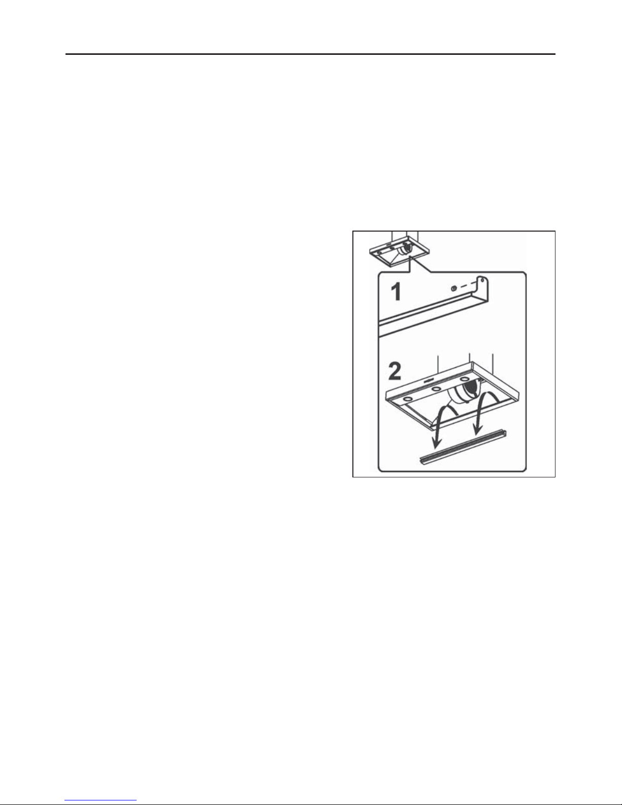
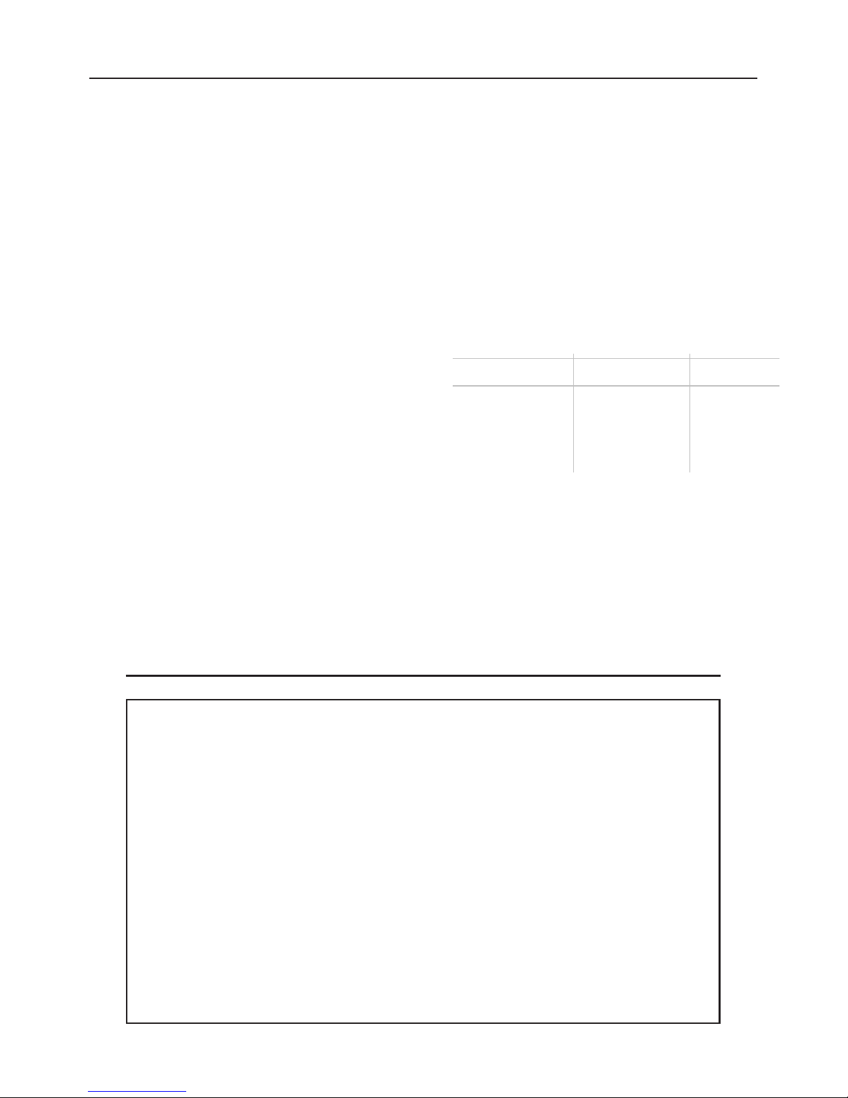
Drip Tray
The drip tray should be cleaned once a month or
as needed. To remove the drip tray, first remove
the baffle grease filters. Unscrew the knobs and
grasp both ends of the drip tray. Gently lift the drip
tray up until the bottom of it clears the track. Pull
the drip tray forward, being careful not to spill the
contents, and move it to a nearby trash receptacle.
To clean the drip tray, drain and wipe all excess
grease with a dry paper towel. Wash with warm
soapy water or in the dishwasher. Dry with a clean
cloth. To replace the drip tray, lift it up and into the
track on the hood. Reinstall knobs and baffle
grease filters.
Non-ducted Recirculation Filter
The non-ducted recirculation filter should be changed every 6 months. Replace more
often if your cooking style generates extra grease, such as frying and wok cooking. See
“INSTALL FILTERS” section for removal and installation instructions.
Stainless Steel Cleaning
DO:
• Regularly wash with clean cloth or rag
soaked with warm water and mild soap or
liquid dish detergent.
• Always clean in the direction of original
polish lines.
• Always rinse well with clear water (2 or 3
times) after cleaning. Wipe dry completely.
• You may also use a specialized
household stainless steel cleaner.
DON’T:
• Use any steel or stainless steel wool or
any other scrapers to remove stubborn dirt.
• Use any harsh or abrasive cleansers.
• Allow dirt to accumulate.
• Let plaster dust or any other construction
residues reach the hood. During
construction/renovation, cover the range
hood to make sure no dust sticks to the
stainless steel surface.
Avoid: When choosing a detergent
• Any cleaners that contain bleach will attack stainless steel
• Any products containing: chloride, fluoride, iodide, bromide will deteriorate surfaces rapidly.
• Any combustible products used for cleaning such as acetone, alcohol, ether, benzol,
etc., are highly explosive and should never be used close to a range.
Page 6
- 6 -
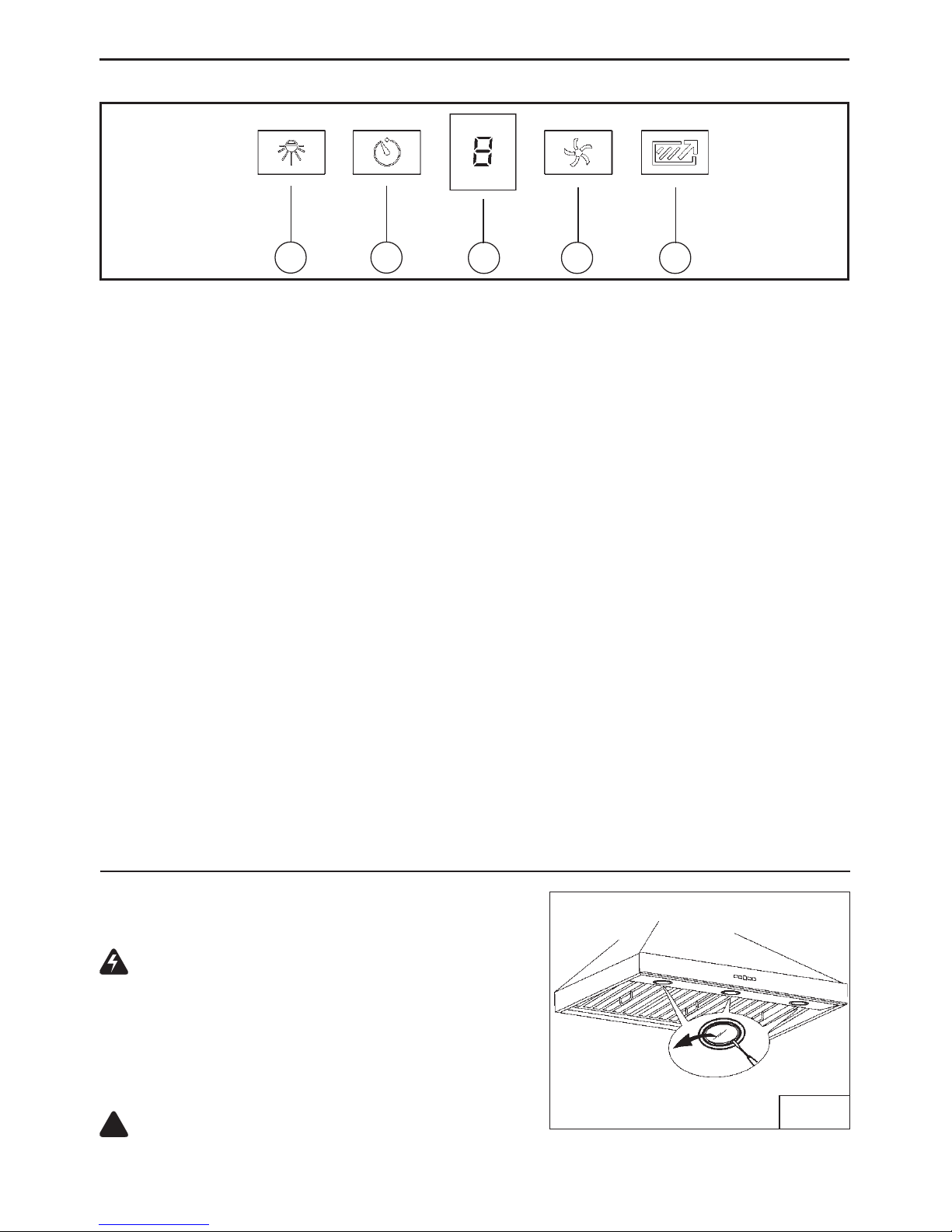
OPERATION
A
C
B
D R
Button A = turns the lights on/low/high/off.
Button B = Activates/Deactivates the delay-off feature. Press once (when blower is on) to
activate the delay-off feature. The selected speed level that is displayed in display “C” will
blink when this feature is activated. After 10 minutes, the blower will then turn off. Delay
can be deactivated at any time by pressing the button again.
Display C = Indicates the selected speed of the blower 1, 2, 3, or b for boost.
“-” indicates the need to clean the grease filter.
Button D = Turns on the blower. Hood will turn on to the last speed selected. The blower
speed will change each time the button is pushed (from 1 to “b”). To turn the blower off,
press and hold button for approximately 2 seconds.
Button R = Filter clean indicator reset. Press and hold for 2 seconds to reset the indicator.
HEAT SENTRY™
Your hood is equipped with a HEAT SENTRY™ thermostat. This thermostat is a device that
will turn on or speed up the blower if it senses excessive heat above the cooking surface.
1) If blower is OFF - it turns blower ON to HIGH speed.
2) If blower is ON at a lower speed setting - it turns blower up to HIGH speed.
When the temperature level drops to normal, the blower will return to its original setting.
WARNING
The HEAT SENTRY thermostat can start the blower even if the hood is turned OFF.
When this occurs, it is impossible to turn the blower OFF with its switch. If you must
stop the blower, do it from the main electrical panel.
Controls (Fig.1)
HALOGEN BULBS
This range hood requires 3 or 4 halogen bulbs (based
on size of hood) (Type T4, 120 Volt, 25 Watt Max, G9
Base).
WARNING: Always switch off the electrical
supply before carrying out any operation on the
appliance.
To change bulbs:
1. Open the cover by gently prying from proper slots
(Fig.2).
2. Remove the bulb by pulling sideways (DO NOT
ROTATE).
CAUTION: Bulb may be hot.
3. Replace with Type T4, 120 Volt, 25 Watt Max, G9 Base halogen bulbs. Do not touch
replacement bulbs with bare hands!
!
FIG. 2
Page 7
- 7 -
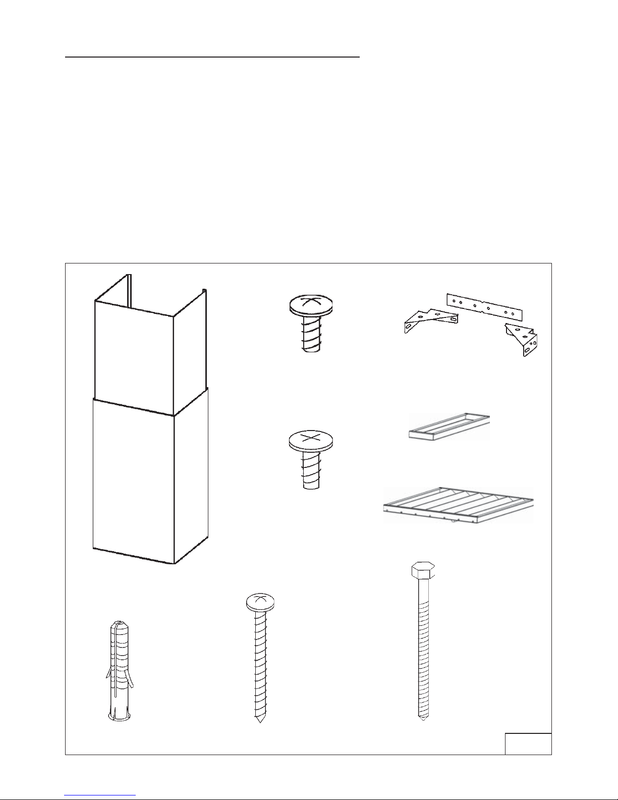
PREPARE THE HOOD
Unpack hood and check contents.
You should receive:
1 - Hood
1 - Decorative Flues
1 - Parts Bag (B080810995) containing:
1 - Flue Mounting Bracket Set
2 - Mounting Screws (3,9 x 6mm Flat Head)
2 - Mounting Screws (3,9 x 9,5mm Pan Head)
4 - Mounting Lag Screws (6 x 60mm)
2 - Mounting Screws (4,8 x 38mm Pan Head)
2 - Drywall Anchors
1 - Installation Instructions
3 - Filters for 36” and 42” or 4 - filters for 48” and 54”
2 - Fillers
FLUE MOUNTING
BRACKET SET
2 MOUNTING SCREWS
(4,8x38mm Pan Head)
DECORATIVE
FLUES
2 MOUNTING
SCREWS (3,9x9,5mm
Pan Head)
2 DRYWALL
ANCHORS
4 MOUNTING LAG
SCREWS (6x60mm)
2 MOUNTING
SCREWS (3,9x6mm
Flat Head)
FIG. 3
3 FILTERS
2 FILLERS
Page 8
- 8 -
EXTERIOR AND IN-LINE BLOWER SELECTION WPP9E Series
CAUTION: To reduce risk of fire and electric shock, install this range hood only with Best
Exterior Blower Models EB6, EB9, EB12 or EB15, and Best In-Line Blower Models ILB3, ILB6,
ILB9 or ILB11. Other blowers cannot be substituited.
The blower must be UL listed for Canadian and U.S. use, and evaluated for use with solid state
speed control, rated 120V, 60 Hz, 6.0 A max.
HOOD
24” TO 36” ABOVE
COOKING SURFACE
DECORATIVE
FLUE
10” ROUND
DUCT
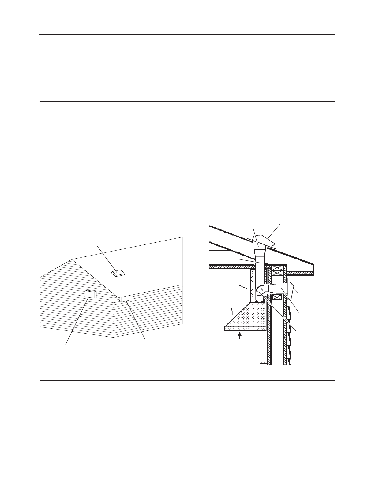
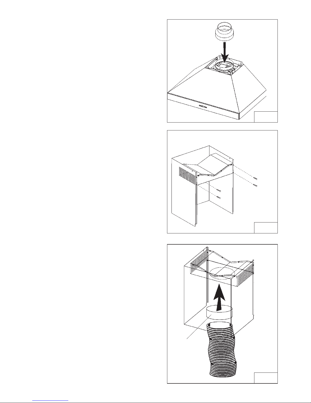
INSTALL THE DUCTWORK WPP9E Series
NOTE: To reduce the risk of fire, use only metal ductwork.
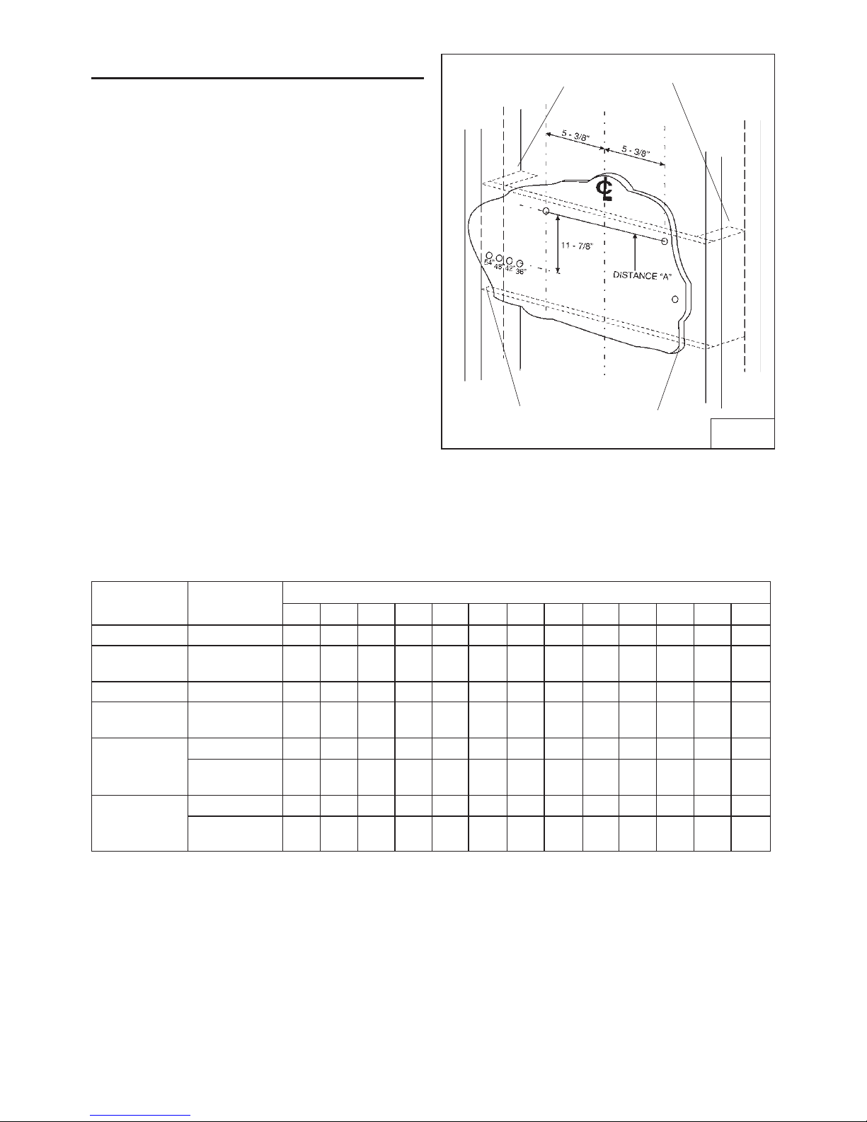
1. Choose the location where the Exterior Blower or In-Line Blower will be mounted. See
illustrations below for mounting location suggestions and restrictions.
2. A straight, short duct run will allow the hood to perform most efficiently.
3. Long duct runs, elbows and transitions will reduce the performance of the hood. Use as
few of them as possible. Larger ducting may be required for best performance with long
duct runs.
4. After the Exterior or In-Line Blower has been installed, connect round metal ductwork
and work back towards the hood location. Use duct tape to seal joints between ductwork
sections.
OK
OK
SUGGESTED MOUNTING LOCATIONS
EXTERIOR BLOWER
CAUTION: MAY NOT FIT
UNDER EAVES OF SINGLE
STORY HOMES
EXTERIOR
BLOWER
10” ROUND
DUCT
EXTERIOR
BLOWER
10” ROUND
ELBOW
10”
ROUND
DUCT
FIG. 4
5 - 3/8”
CENTERLINE OF
DUCT TO WALL
Page 9
- 9 -
IN-LINE BLOWER
FIG. 5
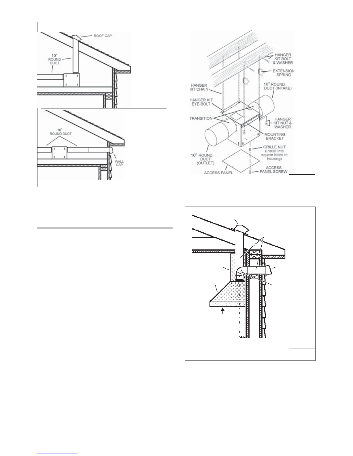
INSTALL THE DUCTWORK
(WPP9IQ and WPP9IQT)
NOTE: To reduce the risk of fire, use only
metal ductwork.
1. Decide where the ductwork will run
between the hood and the outside.
2. A straight, short duct run will allow the hood
to perform most efficiently.
It is recommended that there be a minimum
of 6” of straight duct from to an elbow for 8”
duct and 12” for 10” duct.
3. Long duct runs, elbows, and transitions will
reduce the performance of the hood. Use
as few of them as possible.
4. Install a roof or wall cap. Connect 8" WPPIQ
(or 10” WPPIQT) round metal ductwork to
cap and work back towards hood location.
Use duct tape to seal the joints between
ductwork sections (Fig.6).
24” TO 36” ABOVE
COOKING SURFACE
ROOF CAP
WALL
CAP
8” OR 10” ROUND
ELBOW
HOOD
DECORATIVE
FLUE
8” OR 10” ROUND
DUCT
FIG.6
8” DUCT (5 - 1/8”)
10” DUCT (5 - 3/8”)
CENTERLINE OF
DUCT TO WALL
Page 10
- 10 -
INSTALL THE HOOD
Remove the plastic protective film from all
exterior surfaces, decorative flues and filters,
prior to final installation
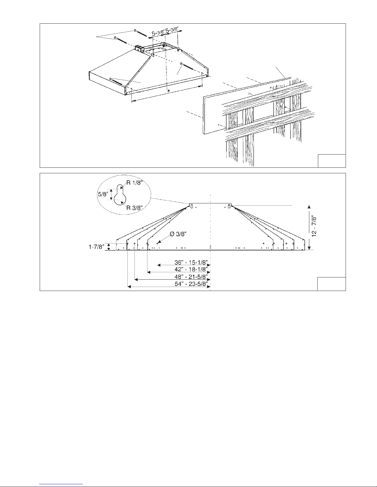
1. Construct wood wall framing that is flush with
interior surface of wall studs (Fig.7).
Make sure:
a) the framing is centered over installation
location.
b) the height of the framing will allow the hood to
be secured to the framing within the
dimensions shown.
2. Install the (2) 6 x 60mm screws for the top of
the hood at the dimensions shown in Fig.8-9.
Use the two outer keyhole slots, do not
completely tighten the screws.
3. Hang the hood onto the screws.
4. Level the hood and secure (2) 6 x 60mm screws
at the outer locations of the hood. Tighten all
(4) screws.
Notes:
a. Minimum hood distance above cook top must
not be less than 24”. A maximum of 36” above
cook top is highly recommended for best
capture of cooking impurities. Distances over
36” are the installer and user discretion.
FIG. 7
FRAMING BEHIND WOOD
CROSS SUPPORT
WOOD CROSS
SUPPORT BEHIND
DRYWALL
DRYWALL
Ceiling
Height
Duct
Method
Hood Distance Above 36” High Cook Top (in.)
24
25 26 28 29 30 31 32 33 34 35 36 27
X X X X X X X 8 Feet Ducted
Non-
Ducted
X X
X X X X X X
X* X* X* X X X X 9 Feet Ducted
Non-
Ducted
X X X X X X X
X X X X X X X X 10 Feet
(see note b)
Ducted
Non-
Ducted
X X
X X X X X X X X X X
X X X X X
11 Feet
(see note a & b)
Ducted
Non-
Ducted
X X X X X
X = Possible Installation Heights
X* = Possible Installation Heights but the Non-Duct Filter Slots will be exposed on
WPP9IQ36SB & WPP9IQ42SB
Notes:
a. Minimum hood distance above cook top must not be less than 24”. A maximum of
36” above cook top is highly recommended for best capture of cooking impurities.
Distances over 36” are at the installer and the users discretion; and if ceiling height
and flue lenght permit.
b. Requires optional 10’ flue extension, ducted model AEWPP9SB or non-ducted
model AEWPP9SBN.
Page 11
- 11 -
MOUNTING LAG
SCREWS (6x60mm)
WALL
FRAMING
MOUNTING LAG
SCREWS (6x60mm)
FIG. 8
FIG. 9
Page 12
- 12 -
WIRING (WPP9IQ and WPP9IQT)
Note: This range hood must be properly
grounded. The unit should be installed by a
qualified electrician in accordance with all
applicable national and local electrical codes.
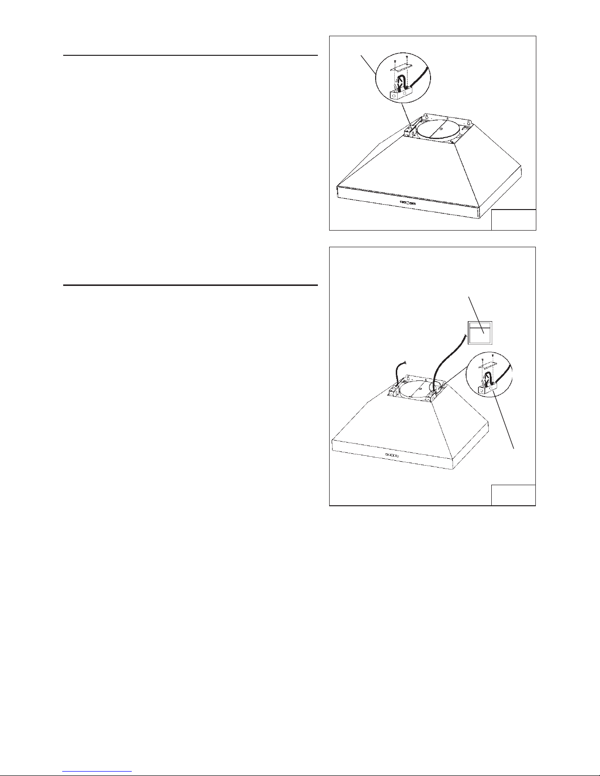
1. Remove the wiring box cover. Remove a
knockout from the wiring box (Fig.10).
2. Secure the conduit to the wiring box through a
conduit connector.
3. Make electrical connections. Connect white to
white, black to black and green to green.
4. Replace wiring box cover and screws. Make sure
that wires are not pinched between cover and
box.
ADDITIONAL EXTERNAL
BLOWER WIRING (WPP9E)
1. Run 2-wire plus ground power cable from the
exterior blower to the hood’s wiring box marked
“motor connection” (Fig.11).
2. Remove the cover from the wiring box and
remove one knockout.
3. Feed 6” of cable through the knockout opening
and secure the cable to the wiring box with an
appropriate connector.
4. Make electrical connections at the hood.
Connect white-to-white, red-to-black and
green-to-ground.
5. Replace the wiring box cover and screws.
Make sure wires are not pinched between the
cover and box.
Exterior blower connection:
1. Make electrical connections at the exterior
blower (see instructions provided with the
exterior blower).
WIRING BOX
COVER
EXTERIOR BLOWER
BLOWER CONNECTION AT HOOD
BOX MARKED
“MOTOR
CONNECTION”
CONNECT:
WHITE-TO-WHITE,
RED-TO-BLACK,
GREEN-TO-GROUND.
FIG.11
FIG.10
Page 13
- 13 -
MOUNTING SCREWS
(4,8x38mm)
MOUNTING SCREWS
(3,9x9,5mm Pan Head)
INSTALL FLUE MOUNTING
BRACKET
DUCTED AND NON-DUCTED
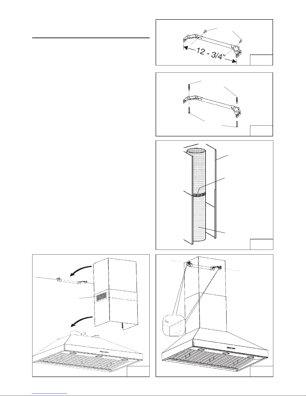
1.Assemble the flue mounting bracket,
adjusting outside width as shown. (Fig.12)
2.Carefully center the mounting bracket directly
over the range hood location.
3.Secure the bracket assembly to the ceiling
using (2) 4.8 x 38mm mounting screws and
drywall anchors (Fig.13). Make sure the
bracket is pushed into the corner, tight against
the wall if necessary, and centered over the
hood. Complete the installation.
DUCTED INSTALLATION ONLY
Note: Rooms with 10 or 11 foot ceilings
require flue extension model AEWPP9SB,
available from your local dealer. Discard
the upper flue supplied with the range
hood and replace it with the longer flue
extension.
1. Attach ductwork to damper/duct connector.
2. Run 8” WPPIQ or 10” WPPIQT & WPPE
diameter metal ductwork to the outside
location (Fig.14).
3. Install an appropriate wall or roof cap with
damper to exhaust the air to the outside.
4. Tape all duct joints with aluminum duct tape.
5. Install upper and lower decorative flues
onto the range hood. Vents are concealed
on 8-foot ceilings. Vents maybe exposed
on 9-foot ceilings (Fig.15).
6. Secure upper flue to flue mounting bracket
with (2) 3.9 x 6mm screws (Fig.16).
8" or 10” ROUND
METAL DUCT
DECORATIVE
FLUE
DUCT TAPE
CEILING
CONCEALED
VENTS
DRYWALL
ANCHORS
FIG. 12
FIG. 13
FIG. 14
FIG. 15 FIG. 16
Page 14
- 14 -
NON-DUCTED INSTALLATION AVAILABLE
ONLY FOR SINGLE BLOWER VERSION
(WPP9IQ only)
Note:
a. Purchase Model ANKWPP9 Non-ducted
Recirculation Kit from your local dealer.
b. Rooms with 10 or 11 foot ceilings require
Flue Extension Model AEWPP9SBN,
available from your local dealer. Discard
the upper flue supplied with the range
hood and replace it with the longer flue
extension.
1. Attach the 6”-to-8” adapter to blower
discharge and tape joint with aluminum
duct tape (Fig.16).
2. Install the plenum to the upper decorative
flue using (4) 3.9 x 6mm flat head screws
provided as shown (Fig.17).
3. Attach 6” expandable ducting to the
plenum using the adapter and tape joints
with aluminum duct tape (Fig.18).
4. Slide upper flue into lower flue.
5. Attach flue assembly to hood.
6. Attach flex duct to plenum through the duct
connector (Fig.18).
7. Attach upper flue to flue bracket using (2)
3.9 x 6mm flat head screws.
MOUNTING SCREWS
(3,9x6mm Flat Head)
FIG. 16
FIG. 17
FIG. 18
DUCT
CONNECTOR
Page 15
- 15 -
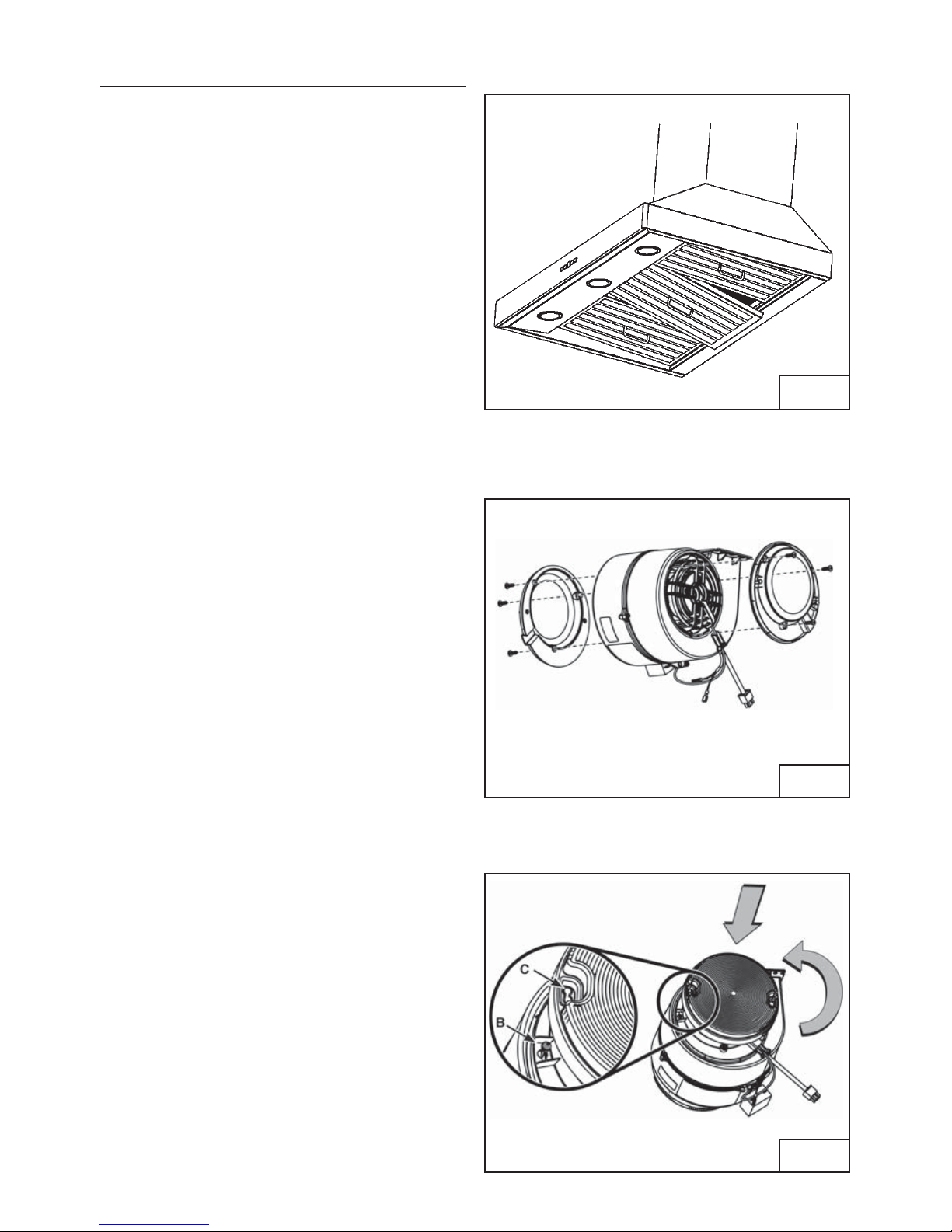
INSTALL FILTERS
DUCTED AND NON-DUCTED HOODS
1.To remove the GREASE filter, (Fig.19) push
the filter towards the front so that it clears
the filter channel, then pull down on the
handle to disengage the filter from the
hood. Tilt the filter downward and remove.
2. The grease filters and the drip tray (see
page 5 for removal & cleaning instructions)
should be cleaned frequently. Use a warm
detergent solution. Grease filters and the
oil collectors are dishwasher safe.
3.To install the GREASE filter, align rear filter
tabs with spring in the hood. Pull down
handle, push filter into position and release.
Make sure the filter is securely engaged
after installation.
NOTE: Prior to use, remove protective film
from the filter frame.
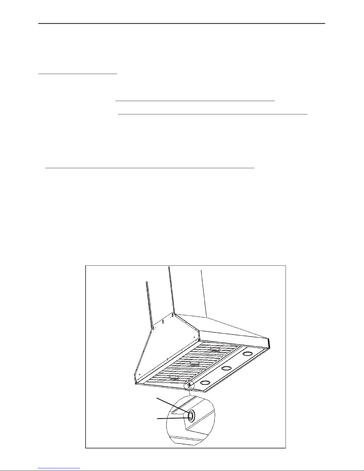
NON-DUCTED HOODS (SINGLE MOTOR
VERSION
WPP9IQ only)
1. Non-ducted recirculation filters not
included. They must be purchased
separately (ANKWPP9 Kit).
2. Using no.6 x 1/2” screws, install one filter
support on each side (provided) of the
internal blower (Fig.20).
3. Position each filter over its support, insert
both pins (B) into the round slot (C) on
filter side and rotate to lock in place
(Fig.21).
Non-ducted recirculation filters
The non-ducted recirculation filters should
be changed every 6 months. Rotate the filters
to remove and replace.
FIG. 19
FIG. 20
FIG. 21
Page 16
- 16 -
CALIBRATION LIGHT
CALIBRATION
BUTTON
CALIBRATE IQ BLOWER SYSTEM
TM
INTERNAL BLOWER DUCTED UNITS ONLY
After the hood is installed and wired, engage the calibration process (our Guaranteed Performance
System Technology to ensure full-rated airflow is being delivered). Prior to calibration, ensure that all
filters, light bulbs and duct system are installed.
CALIBRATION PROCESS
Hold the calibration button for 3 seconds; calibration button will light up and stay on for up to 13 minutes.
The blower will start and begin the calibration process. When calibration is complete, one of two things
will occur:
1. The blower turns off and
calibration button light stays on = Successful calibration. Press the button
to turn off the LED. Note: The LED will also turn off if you select any blower speed on the control.
2. The blower turns off and
calibration button light blinks continuously = Too much restriction in the
ductwork is preventing the IQ Blower System™ from achieving the rated airflow. The blower is
automatically set to maximum intensity.
NOTE: Common items that cause restrictions: restricted damper flap (backdraft damper, wall cap,
roof cap), too many elbows, duct size less than 80% of hood outlet, poor transition, use of flex ducting
and/or crushed ducting.
Three options are available if your hood system has too much restriction:
1. Accept airflow as is.
a. Press the calibration button to accept airflow as is. The IQ Blower System™ is nowconfigured to
the highest possible performance. The blinking calibration light goes out. Note: The LED will also
turn off if you select any blower speed on the control.
2. Correct duct restriction, clear the original calibration data, and repeat the calibration process.
a. Correct the duct restriction.
b. Clear the original calibration data by holding calibration button for 10 seconds. The light will blink
3 times to confirm and the blower configuration will go back to default settings.
c. Repeat calibration process from the beginning.
3. Clear calibration data to reset hood to default factory setting and achieve standard high
pressure blower performance.
a. Clear calibration data and reset hood to factory default setting by holding calibration
button for 10 seconds. The light will blink 3 times to confirm and the blower configuration
will go back to default settings.
Page 17
- 17 -
WARRANTY
ONE YEAR LIMITED WARRANTY FOR BEST PRODUCTS
Broan-NuTone LLC (Broan-NuTone) warrants to the original consumer purchaser of Best products that such products will be free
from defects in materials or workmanship for a period of one year from the date of original purchase. THERE ARE NO OTHER
WARRANTIES, EXPRESS OR IMPLIED, INCLUDING, BUT NOT LIMITED TO, IMPLIED WARRANTIES OR MERCHANT ABILITY
OR FITNESS FOR A PARTICULAR PURPOSE.
During this one-year period, Broan-NuTone will, at its option, repair or replace, without charge, any product or part which is found
to be defective under normal use and service.
THIS WARRANTY DOES NOT EXTEND TO FLUORESCENT LAMP STARTERS, TUBES, HALOGEN AND INCANDESCENT
BULBS, FUSE, FILTERS, DUCTS, ROOF CAPS, WALL CAPS AND OTHER ACCESSORIES FOR DUCTING. This warranty does
not cover (a) normal maintenance and service or (b) any products or parts which have been subject to misuse, negligence,
accident, improper maintenance or repair (other than by Broan-NuTone), faulty installation or installation contrary to recommended installation instructions.
The duration of any implied warranty is limited to the one-year period as specified for the express warranty. Some states do not
allow limitation on how long an implied warranty lasts, so the above limitation may not apply to you.
BROAN-NUTONE'S OBLIGATION TO REPAIR OR REPLACE, AT BROAN-NUTONE'S OPTION, SHALL BE THE PURCHASER'S
SOLE AND EXCLUSIVE REMEDY UNDER THIS WARRANTY. BROAN-NUTONE SHALL NOT BE LIABLE FOR INCIDENTAL,
CONSEQUENTIAL OR SPECIAL DAMAGES ARISING OUT OF OR IN CONNECTION WITH PRODUCT USE OR PERFORMANCE.
Some states do not allow the exclusion or limitation of incidental or consequential damages, so the above limitation or exclusion
may not apply to you.
This warranty gives you specific legal rights, and you may also have other rights, which vary from state to state. This warranty
supersedes all prior warranties.
To qualify for warranty service, you must (a) notify Broan-NuTone at the address stated below or telephone number stated below,
(b) give the model number and part identification and (c) describe the nature of any defect in the product or part. At the time of
requesting warranty service, you must present evidence of the original purchase date.
In USA - Best®, 926 W. State Street, Hartford, WI 53027 (800-558-1711)
In Canada - Best®, 550 Lemire Blvd., Drummondville, QC J2C 7W9 (866-737-7770)
www.BestRangeHoods.com
WPP9 Programming Mode Procedure
WPP9E Programming Mode Procedure
The range hood is designed to work with several different blowers models. Before using the
hood, the control must first be programmed to your blower model, in order to achieve proper
operating speed:
1.Find the SETUP number that corresponds to the blower model that is installed with your
range hood.
2.There must be power to the hood but the blower and lights must be turned off.
3.Push simultaneously LIGHT SWITCH and RESET SWITCH for 5 sec: the display shows a
“P” blinking three times and then shows alternately the “P” and the setup selected.
4.Select the desired setup with BLOWER SWITCH (3
Î2Î1) or RESET SWITCH
(1
Î2Î3).
5. Push TIMER SWITCH to confirm.
6. The display (“P”) blinks two times ( 2 sec on - 0,5sec off) recording the selected setup.
SETUP 1
SETUP 1
SETUP 2
SETUP 2
SETUP 3
SETUP 3
EB6
ILB3
ILB6
EB12
EB15
ILB9
EB9
ILB11
Description of “Speed Level”
Setup 1 is for motors with a rating up to 3.0 amp
Setup 2 is for motors with a rating between 3.1 amp and 5.0 amp
Setup 3 is for motors with a rating greater than 5.1 to 6 amp
Page 18
- 18 -
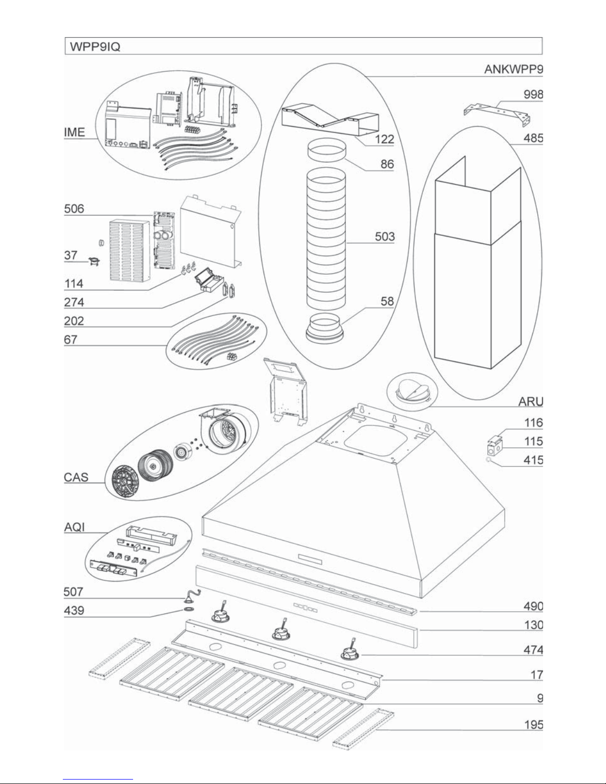
KEY NO. PART NO. DESCRIPTION
9 B08087951 Grease Filters
17 BE3351882 Light Diffuser Support 36”
17 BE3351898 Light Diffuser Support 42”
37 B02300804 Heat Sentry
67 B06102602 Wires Assembly
114 B032904990 Wire Clamp
115 BE3350233 Wiring Box
116 BE3334252 Wiring Box Cover
130 BE3405180 Front trim 36”
130 BE3405184 Front trim 42”
195 BE3351870 Filter Spacers 42” only
202 B03292290 Wire Clamp
274 B03295035 Fuse Box
415 B03292596 Fairlead
439 B02320034 Grommet
474 B02300918 Halogen Lamp
485 B08016372 Decorative Flue Assembly
490 BE3405182 Grease Rails 36”
490 BE3405185 Grease Rails 42”
506 97019432 BLDC Driver
507 B06102584 Calibration Button Assembly
* B080810995 Fitting Set (Includes Key No. 998)
AQI B06102596 Switch Box Assembly
ARU B08092501 Duct Connector Assembly 8”
IME B06145225 Electrical Installation Assembly
CAS B06002259 Blower Assembly
ANKWPP9 B08999177 Non-Ducted Kit (Includes Key No. 58, 86, 122, 503)
58 B03294170 Outlet Reduction
86 B03292300 Outlet Flange
122 B08093448 Riser
503 B02011557 Expandable Duct
AFCROUND2 99111455 Non-Duct Filter Supports
* Not shown assembled.
SERVICE PARTS
MODEL WPP9IQ
Page 19
- 19 -
Page 20

- 20 -
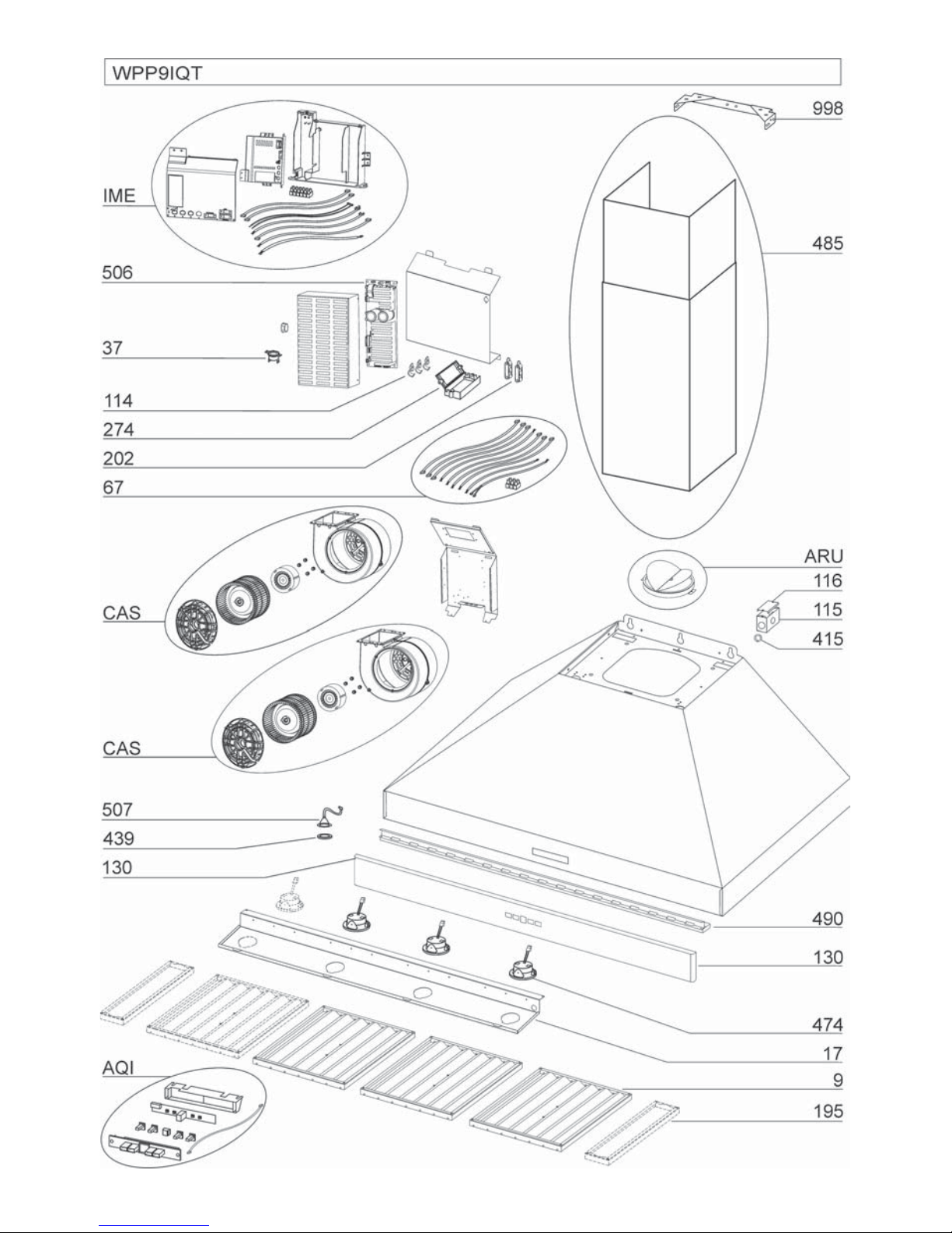
KEY NO. PART NO. DESCRIPTION
9 B08087951 Grease Filters
17 BE3351882 Light Diffuser Support 36”
17 BE3351898 Light Diffuser Support 42”
17 BE3351906 Light Diffuser Support 48”
17 BE3351915 Light Diffuser Support 54”
37 B02300804 Heat Sentry
67 B06102603 Wires Assembly 36” or 42”
67 B06102606 Wires Assembly 48” or 54”
114 B032904990 Wire Clamp
115 BE3350233 Wiring Box
116 BE3334252 Wiring Box Cover
130 BE3405180 Front trim 36”
130 BE3405184 Front trim 42”
130 BE3405187 Front trim 48”
130 BE3405190 Front trim 54”
195 BE3351870 Filter Spacers 42” and 54” only
202 B03292290 Wire Clamp
274 B03295035 Fuse Box
415 B03292596 Fairlead
439 B02320034 Grommet
474 B02300918 Halogen Lamp
485 B08016379 Decorative Flue Assembly
490 BE3405182 Grease Rails 36”
490 BE3405185 Grease Rails 42”
490 BE3405188 Grease Rails 48” (2 required)
490 BE3405191 Grease Rails 54” (2 required)
506 97019434 BLDC Driver
507 B06102584 Calibration Button Assembly
* B080810995 Fitting Set (Includes Key No. 998)
AQI B06102596 Switch Box Assembly
ARU BE3405192 Duct Connector Assembly 10”
IME B06145225 Electrical Installation Assembly
CAS B06002259 Blower Assembly
* Not shown assembled.
SERVICE PARTS
MODEL WPP9IQT
Page 21
- 21 -
Page 22
- 22 -
KEY NO. PART NO. DESCRIPTION
9 B08087951 Grease Filters
17 BE3351882 Light Diffuser Support 36”
17 BE3351898 Light Diffuser Support 42”
17 BE3351906 Light Diffuser Support 48”
17 BE3351915 Light Diffuser Support 54”
37 B02300804 Heat Sentry
67 B06102604 Wires Assembly 36” or 42”
67 B06102614 Wires Assembly 48” or 54”
114 B032904990 Runner Wires
115 BE3350233 Wiring Box
116 BE3334252 Wiring Box Cover
130 BE3405180 Front trim 36”
130 BE3405184 Front trim 42”
130 BE3405187 Front trim 48”
130 BE3405190 Front trim 54”
195 BE3351870 Filter Spacers 42” and 54” only
202 B03292290 Wire Clamp
274 B03295035 Fuse Box
415 B03292596 Fairlead
474 B02300918 Halogen Lamp
485 B08016379 Decorative Flue Assembly
490 BE3405182 Grease Rails 36”
490 BE3405185 Grease Rails 42”
490 BE3405188 Grease Rails 48” (2 required)
490 BE3405191 Grease Rails 54” (2 required)
* B080810995 Fitting Set (Includes Key No. 998)
AQI B06102605 Switch Box Assembly
ARU BE3405192 Duct Connector Assembly 10”
IME B06145226 Electrical Installation Assembly
* Not shown assembled.
SERVICE PARTS
MODEL WPP9E
Page 23

- 23 -
Page 24

- 24 -
Page 25

- 25 -
Aux États-Unis - BEST Hartford, Wisconsin
Au CANADA - BEST Drummondville, QC, Canada
Modèle WPP9
ENREGISTREZ VOTRE PRODUIT EN LIGNE À : www.BestRangeHoods.com/register
Pour de plus amples informations, visitez www.BestRangeHoods.com
ENGLISH........................................3
FRANÇAIS...................................25
ESPAÑOL.....................................49
Page 26

- 26 -
Page 27

- 27 -
LIRE CES DIRECTIVES ET LES CONSERVER
CONÇUE POUR LES CUISINES PRIVÉES UNIQUEMENT
!
!
AVERTISSEMENTS
POUR RÉDUIRE LES RISQUES D’INCENDIE, D’ÉLECTROCUTION OU DE BLESSURES
PHYSIQUES, RESPECTEZ LES INSTRUCTIONS CI-DESSOU:
1. Utilisez cet appareil uniquement de la manière prévue par le fabricant. Si vous avez des questions, contactez le fabricant à l’adresse ou au numéro de téléphone indiqués dans la garantie.
2. Avant d’effectuer l’entretien ou le nettoyage de l’appareil, mettez-le hors tension sur le panneau
de service et verrouillez ce dernier pour éviter que l’appareil soit mis sous tension par
inadvertance. S’il n’est pas possible de verrouiller le dispositif de déconnexion, apposez un
avertissement bien visible (par exemple une étiquette) sur le panneau de service.
3. L’installation et le raccordement électrique doivent être effectués par du personnel qualifié conformément à toutes les réglementations et normes en vigueur, y compris celles concernant les
constructions cotées pour leur résistance au feu.
4. Afin d’éviter un refoulement lors de l’utilisation d’équipements à combustible, une quantité d’air
suffisante est nécessaire pour assurer une combustion et un échappement adéquats des gaz à
travers le conduit (la cheminée). Suivez les consignes du fabricant de l’équipement chauffant et
les normes de sécurité publiées, entre autres, par l’Association nationale de protection contre
l’incendie (NFPA) et l’American Society for Heating, Refrigeration and Air Conditioning Engineers
(ASHRAE), ainsi que les réglementations locales.
5. Quand vous effectuez une découpe ou un forage dans un mur ou un plafond, veillez à ne pas
endommager des câblages électriques ou d’autres équipements non visibles.
6. Les soufflantes canalisées doivent toujours être dirigées vers l’extérieur.
7. N’utilisez pas cet appareil avec un dispositif de commande de vitesse transistorisée séparé.
8. Pour réduire les risques d’incendie, utilisez uniquement des canalisations en métal.
INSTRUCTIONS DE MISE À LA TERRE
Cet appareil doit être mis à la terre. En cas de court-circuit électrique, la mise à la terre réduit le
risque d’électrocution grâce à un fil permettant au courant électrique de s’échapper.
AVERTISSEMENT - Une mise à la terre inappropriée peut donner lieu à un risque d’électrocution.
Consultez un électricien qualifié si vous ne comprenez pas parfaitement les instructions de mise à
la terre ou si vous n’êtes pas certain(e) que l’appareil est mis à la terre comme il se doit.
POUR RÉDUIRE LE RISQUE D’UN FEU DE FRITURE SUR LA TABLE DE CUISSON
A. Ne laissez jamais les appareils de surface sans surveillance quand ils sont sur un réglage élevé.
Les débordements peuvent provoquer de la fumée et des déversements gras risquant de
prendre feu. Chauffez les huiles lentement sur un réglage bas ou moyen.
B. ALLUMEZ toujours la hotte quand vous cuisinez à une chaleur élevée ou quand vous flambez
des aliments (p. ex. des crêpes Suzette, des cerises jubilé ou du boeuf au poivre flambé).
C. Nettoyez souvent les ventilateurs d’aération. Évitez que de la graisse s’accumule sur le
ventilateur ou le filtre.
D. Utilisez des poêles de la taille appropriée. Utilisez toujours des ustensiles de cuisine adaptés à la
taille de l’élément de surface.
Page 28

- 28 -
AVERTISSEMENTS
POUR RÉDUIRE LE RISQUE DE BLESSURES PHYSIQUES EN CAS DE FEU DE FRITURE
SUR LA TABLE DE CUISSON, VEUILLEZ PROCÉDER COMME SUIT :*
1. ÉTOUFFEZ LES FLAMMES avec un couvercle hermétique, une plaque à biscuits ou un
plateau en métal, puis éteignez le brûleur. SOYEZ PRUDENT(E) AFIN D’ÉVITER LES
BRÛLURES. Si les flammes ne s’éteignent pas immédiatement, ÉVACUEZ LE LIEU ET
APPELEZ LE SERVICE DES POMPIERS. 2. NE SAISISSEZ JAMAIS UNE POÊLE
ENFLAMMÉE, vous risquez de vous brûler.
3. N’UTILISEZ JAMAIS D’EAU ni de torchons ou serviettes mouillé(e)s : cela donnerait lieu à une
violente explosion de vapeur.
4. Utilisez un extincteur UNIQUEMENT si :
A. Vous savez qu’il s’agit d’un extincteur de Classe ABC et savez déjà comment vous en servir.
B. L’incendie est de petite taille et confiné à l’endroit où il a commencé.
C. Le service des pompiers a été averti.
D. Vous pouvez éteindre l’incendie en ayant une sortie derrière vous.
* Basé sur « Kitchen Fire Safety Tips », publié par la NFPA.
ATTENTION
1. Uniquement pour l’utilisation intérieure.
2. Pour réduire le risque d’incendie et obtenir un échappement d’air adéquat, veillez à bien canaliser l’air vers l’extérieur. Ne ventilez pas l’air d’échappement vers des espaces confinés,
des plafonds, des combles, des vides sanitaires ou des garages.
3. Soyez prudent(e) quand vous utilisez des agents de nettoyage ou des détergents.
4. Évitez d’utiliser sous la hotte de cuisine des denrées alimentaires produisant des flammes.
5. À utiliser uniquement pour la ventilation générale. N’utilisez pas la hotte pour l’échappement de
matériaux ou de vapeurs comportant un danger ou un risque d’explosion.
6. Pour éviter que le roulement moteur s’endommage et que des hélices deviennent bruyantes ou
déséquilibrées, faites en sorte que le bloc d’alimentation n’entre pas en contact avec un
atomiseur pour cloisons sèches, de la poussière de construction, etc.
7. Le moteur de la hotte est doté d’un rupteur thermique qui éteint automatiquement le moteur en
cas de surchauffe. Le moteur redémarrera après avoir refroidi. Si le moteur s’éteint et se
rallume constamment, faites réparer la hotte.
8. Pour mieux capturer les impuretés de cuisson, la partie inférieure de la hotte doit se trouver au
minimum à 61 cm (24”) et au maximum à 91 cm (36”) au-dessus de la surface de cuisson.
Consultez la section « Installation du support de montage » pour connaître les restrictions de
montage.
9. Étant donné la taille et le poids de la hotte, il est conseillé d’avoir recours à deux personnes
pour la monter.
10. Ce produit est doté d’un thermostat qui peut activer la soufflante automatiquement. Pour éviter
les risques de blessure et l’allumage accidentel de la hotte, mettez-la hors tension sur le
panneau de service et verrouillez ce dernier ou fixez-y une étiquette d’avertissement.
11. Pour en savoir plus et connaître les exigences sur le produit, veuillez lire l’étiquette des
spécifications.
12. MODÈLES VENTILATEUR EXTERNE SEULEMENT: Pour réduire les risques d’incendie ou de
choc électrique, installez cette hotte uniquement avec les modèles de ventilateur extérieur Best
EB6, EB9, EB12 ou EB15, ou les modèles de ventilateur intermédiaire BestILB3, ILB6, ILB9 ou
ILB11. Aucun autre ventilateur ne peut être substitué (Ventilateur vendu séparément).
!
Page 29

- 29 -
NETTOYAGE ET ENTRETIEN
Pour assurer les performances de l'appareil, entretenez-le de manière appropriée.
Moteur
Le moteur est lubrifié en permanence et aucun graissage n'est nécessaire. Si les roulements
du moteur font un bruit excessif ou inhabituel, remplacez le moteur par une pièce de rechange
identique.
Remplacez aussi les hélices.
Filtre à graisse
Le filtre à graisse doit être nettoyé souvent. Vous pouvez utiliser une solution détergente
chaude ou le mettre dans le lave-vaisselle.
Nettoyez tous les filtres en métal dans le lave-vaisselle avec un détergent sans phosphate.
Si vous utilisez un détergent phosphaté ou selon le type d'eau, il est possible que le filtre se
décolore, mais cela n'affectera aucunement ses performances. Cette décoloration n'est pas
couverte par la garantie. Consultez la section « INSTALLATION DES FILTRES » pour
connaître les instructions de retrait et d'installation.
Gouttière
La gouttière doit être nettoyée une fois par mois ou
au besoin. Pour enlever la gouttière, enlevez d’abord
les filtres à graisses avec déflecteurs métalliques et
les arrêts. Saisissez les deux extrémités de la
gouttière. Soulevez-la doucement jusqu’à ce que le
fond de la gouttière soit dégagé du rail. Tirez la
gouttière vers vous, en faisant attention de ne pas en
renverser le contenu, puis videz le contenu dans une
poubelle. Après avoir vidé la gouttière, essuyez le
surplus de graisse avec un essuie-tout sec. Lavez-la
ensuite dans de l’eau chaude savonneuse ou au
lave-vaisselle. Essuyez-la avec un chiffon propre.
Pour remettre la gouttière en place, soulevez-la et
insérez-la dans le rail de la hotte. Remettez en place
les arrêts et les filtres à graisses avec déflecteurs
métalliques.
Filtre de recirculation non canalisé
Le filtre de recirculation non canalisé doit être changé
tous les 6 mois. Si votre style de cuisine engendre
beaucoup de graisse, par exemple si vous faites
souvent de la friture ou utilisez un wok, remplacez-le plus souvent. Consultez la section
« INSTALLATION DES FILTRES » pour connaître les instructions de retrait et d'installation.
Nettoyage de l'acier inoxydable
À FAIRE :
• nettoyez régulièrement l'acier inoxydable
avec un chiffon ou un torchon enduit d'eau
chaude et de savon doux ou de liquide
vaisselle.
• nettoyez toujours dans le sens des lignes
de polissage d'origine.
• rincez toujours à l'eau claire (2 ou 3 fois)
après le nettoyage. Essuyez
complètement.
• vous pouvez aussi utiliser un nettoyant
spécial pour acier inoxydable
d'électroménagers.
À NE PAS FAIRE :
• n'utilisez pas de laine d'acier inoxydable
ou d'autres racloirs pour éliminer la saleté
difficile à éliminer.
• n'utilisez pas de produits de nettoyage durs
ou abrasifs.
• ne laissez pas la poussière s'accumuler.
• maintenez la hotte à l'abri de la poussière
de plâtre ou d'autres résidus de
construction. Pen-dant la construction/les
rénovations, couvrez la hotte afin d'éviter
qu'aucune poussière n'adhère aux surfaces
en acier inoxydable.
À éviter quand vous choisissez un détergent :
• tous les produits de nettoyage contenant de l'eau de Javel attaquent l'acier inoxydable.
• tous les produits contenant du chlore, du fluor, de l'iode ou du bromure provoquent une
détérioration rapide des surfaces.
• tous les produits combustibles utilisés pour le nettoyage, tels que l'acétone, l'alcool,
l'éther, le benzène sont extrêmement explosifs et ne doivent jamais être employés à
proximité d'une table de cuisson.
Page 30

- 30 -
FONCTIONNEMENT
COMMANDES (Fig.1)
Bouton A = tourne les lumières / basse / haute / arrêt.
Bouton B = active / désactive la fonction retard-off. Appuyez une fois (lorsque la soufflerie
est activée) pour activer la fonction retard-off. Le niveau de vitesse sélectionnée qui est
affichée dans l’affichage “C” clignote lorsque cette fonction est activée. Après 10 minutes, le
ventilateur s’éteindra. Le retard peut être désactivé à tout moment en appuyant sur le
bouton.
Display C = indique la vitesse sélectionnée du ventilateur 1, 2, 3, ou b pour boost.«-»
Indique la nécessité de nettoyer le filtre à graisse.
Bouton D = Active le ventilateur. Hotte se met en marche à la dernière vitesse sélectionnée.
La vitesse du ventilateur change chaque fois que le bouton est enfoncé (de 1 à “b”). Pour
éteindre le ventilateur, appuyez sur le bouton pendant environ 2 secondes contenir.
Bouton R = Nettoyer le filtre réinitialisation de l’indicateur. Appuyez et maintenez enfoncé
pendant 2 secondes pour réinitialiser l’indicateur.
HEAT SENTRY™
La hotte est équipée d'un thermostat HEAT SENTRY™. Ce dispositif active ou accélère la
soufflante s'il détecte une chaleur excessive au-dessus de la surface de cuisson.1) Si la
soufflante est ARRÊTÉE, il l'ALLUME sur la vitesse HAUTE.2) Si la soufflante est ALLUMÉE
à une vitesse basse, il la fait passer à la vitesse HAUTE.Quand la température redevient
normale, la soufflante retourne au réglage d'origine.
AVERTISSEMENT
Le thermostat HEAT SENTRY peut activer la soufflante même si la hotte est éteinte.
Dans ce cas, il est impossible de désactiver la soufflante avec le commutateur d'ARRÊT.
Si vous devez ARRÊTER la soufflante, faites-le depuis le panneau électrique principal.
AMPOULES HALOGÉNES
Cette hotte de cuisine nécessite 3 ou 4 ampoules
halogène (selon la taille de la hotte) (Type T4, 120
Volt, 25 Watt Max, G9 Base).
AVERTISSEMENT: Désactivez tou-jours
l’alimentation avant d’effectuer toute opération sur
l’appareil.
Pour changer les ampoules :
1. 1. Ouvrez le couvercle en faisant levier sur les fentes
prévues à cet effet (Fig.2).
2. Retirez les ampoules en les tirant vers le côté (NE
LES TOURNEZ PAS).
ATTENTION : Il est possible que les ampoules soient chaudes.
3. Remplacez-les par des ampoules halogènes de type T4, 120 Volt, 25 Watt Max, G9 Base.
Ne touchez pas les ampoules de rechange à mains nues!
!
FIG. 2
A
C
B
D R
Page 31

- 31 -
PRÉPARATION DE LA HOTTE
Déballez la hotte et vérifiez le contenu de l’emballage.
Il doit comprendre :
1 - Hotte
1 - De carneau décoratif
1 - Sac de pièces (B080810995) contenant:
1 - Support de montage carneau
2 - Vis de montage (à tête plate de 3,9 x 6 mm)
2 - Vis de montage (à tête cylindrique de 3,9 x 9,5 mm)
4 - Vis de montage (6 x 60mm)
2 - Vis de montage (à tête cylindrique de 4,8 x 38 mm)
2 - Ancrages pour cloison sèche
1 - Instructions d’installation
3 - Filtres pour 36” et 42” ou 4 - filtres pour 48” et 54”
2 - Spacers filtre
SUPPORT DE
MONTAGE DU
CARNEAU
2 VIS DE MONTAGE (à tête
cylindrique de 4,8 x 38 mm)
CARNEAU
DÉCORATIF
2 VIS DE MONTAGE
(à tête cylindrique de
3,9 x 9,5 mm)
2 ANCRAGES POUR
CLOISON SÈCHE
4 VIS DE MONTAGE
(6x60mm)
2 VIS DE MONTAGE
(à tête plate de
3,9x6mm)
FIG. 3
3 ou 4
FILTRES
2 SPACERS
FILTRE
Page 32

- 32 -
CHOIX DE VENTILATEUR EXTERNE OU “IN-LINE” WPP9E Series
ATTENTION: Pour réduire les risques d’incendie et électrique, installer cette hotte
seulement avec un ventilateur extérieur Best Modèles EB6, EB9, EB12 ou EB15, et les
ventilateur en ligne Best Modèles ILB3, ILB6, ILB9 ou ILB11 uniquement. On ne peut pas
utiliser d’autres ventilateurs (les ventilateurs sont vendus séparément).
Le ventilateur doit être compris dans la liste UL pour l’utilisation au Canada et aux USA et
approuvée pour l’utilisation avec un “dispositif de contrôle de la vitesse” à l’état solide, dont
les données sur la plaque sont 120V, 60 Hz, 6.0 A max.
INSTALLATION DU SYSTEME D’EVACUATION WPP9E Series
NOTE: Pour réduire les risques d’incendie n’utiliser que des conduits métalliques.
1. Choisir l’emplacement où le ventilateur externe ou le ventilateur “In-Line” sera monté. Voir
les illustrations ci-dessous pour le choix de l’emplacement et les éventuelles restrictions à
suivre.
2. Un conduit d’évacuation étroit et court rendra la hotte plus performante.
3. Des conduits d’évacuation longs, avec des coudes et des raccords rendront la hotte moins
efficace. Les utiliser le moins possible. En cas de conduits d’évacuation longs on utilisera
un diamètre supérieur.
4. Après avoir installé le ventilateur externe ou le ventilateur “In-Line”, raccorder le tuyau
métallique rond dans le sens de l’emplacement de la hotte. Utiliser du chaterton pour
fermer hermétiquement les joints entre les tuyaux.
FIG. 4
HOTTE
24” (61cm) À 36” (91cm)
AU-DESSUS DU PLAN
DE CUISSON
CARNEAU
DÉCORATIF
CONDUIT
ROND
DE 10”
OK
OK
SUGGESTIONS POUR LE MONTAGE
VENTILATEUR EXTERNE
ATTENTION: NE PAS INSTALLER
SOUS L’AVANT-TOIT D’UNE
MAISON A UN ETAGE
VENTILATEUR
EXTERNE
CONDUIT ROND
DE 10”
VENTILATEUR
EXTERNE
COUDE
ROND
DE 10”
CONDUIT
ROND
DE 10”
5 - 3/8”
CENTRALE DE
CONDUIT AU MUR
Page 33

- 33 -
VENTILATEUR IN-LINE
FIG. 5
INSTALLER LES CONDUITS
(WPP9IQ et WPP9IQT)
REMARQUE: pour réduire les risques
d’incendie, utilisez uniquement des
conduits métalliques.
1. Décidez où le tuyau doit être installé, entre
votre hotte et l’extérieur.
2. Un conduit droit et court permettra à votre
hotte de fonctionner d’une façon plus efficace.
Il est recommandé qu’il y ait un minimum
de 6” de conduit droit à un coude pour 8”
conduit et 12” pour 10” conduit.
3. Un conduits long avec des coudes et des
transitions réduira le bon fonctionnement de
votre hotte. En utiliser le moins possible.
4. Installez un couvercle sur le toit ou au mur.
Reliez un tuyau en métal rond de 8” WPPIQ
(ou 10” WPPIQT) au couvercle et faites-le
aller jusqu’à l’emplacement de votre hotte.
Utiliser du ruban adhésif pour sceller les
joints entre les sections de conduits
(Fig.6).
24” (61cm) À 36” (91cm)
AU-DESSUS DU PLAN
DE CUISSON
CAPUCHON DU TOIT
CAPUCHON
MURAL
COUDE ROUNDE
DE 8” À 10”
HOTTE
CARNEAU
DÉCORATIF
CONDUIT ROND
DE 8” À 10”
FIG.6
8” CONDUIT (5 - 1/8”)
10” CONDUIT (5 - 3/8”)
CENTRALE DE
CONDUIT AU MUR
Page 34

- 34 -
X = Hauteurs d’installation possibles
X* = Hauteurs d’installation possibles mais le filtre fentes non-canalisèe seront
exposés sur WPP9IQ36SB et WPP9IQ42SB
Remarques:
a. La distance minimale de la hotte au-dessus de la table de cuisson ne doit pas être
inférieure à 24”. Un maximum de 36” au-dessus de la table de cuisson est fortement
recommandé pour une meilleure évacuation des odeurs de cuisson. Distances de
plus de 36” sont les installer et choix de l’utilisateur, et si la hauteur de plafond et le
permis de longueur de combustion.
b. Requiert en option le carneaux extensible à 10 PI, modèle canalisé AEWPP9SB ou
non-canalisèe modèle AEWPP9SBN.
INSTALLEZ LA HOTTE
Remarque : avant l'installation finale, retirez
la pellicule en plastique de toutes les surfaces
extérieures, des carneaux décoratifs et des
filtres.
1. Construisez une structure murale en bois à
niveau avec la surface intérieure des poteaux
de cloison (Fig.7).
Assurez-vous:
a) que la structure est centrée sur l'emplacement
d'installation.
b) que la structure soit placée à une hauteur
permettant d'y fixer le sup-port de montage
conformément aux dimensions indiquées.
2. Installez les deux (2) 6 x 60mm vis de la partie
supérieure du hotte aux dimensions
indiquées dans la Fig.8-9. Utilisez les deux
trous de serrure extérieures, ne serrez pas
complètement les vis.
3. Accrochez la hotte sur les vis.
4. Niveau la hotte et sécurisé (2) 6 x 60mm vis
aux endroits extérieurs de la hotte. Serrer
tous les (4) vis.
Remarques:
a. La distance minimale de la hotte au-dessus de la table de cuisson ne doit pas être
inférieure à 24”. Un maximum de 36” au-dessus de la table de cuisson est fortement
recommandé pour une meilleure évacuation des odeurs de cuisson. Distances de plus
de 36” sont l’installateur et la discrétion de l’utilisateur.
FIG. 7
STRUCTURE DERRIÈRE LE
SUPPORT EN BOIS CROISÉ
SUPPORT EN BOIS
CROISÉ DERRIÈRE
LA CLOISON SÈCHE
CLOISON
SÈCHE
Hauter
de
Plafond
Méthode de
Canalisation
Distance de la Hotte à 90 cm (36”) au-dessus de la Table de Cuisson (voir note a.)
24 25 26 28 29 30 31 32 33 34 35 36 27
X X X X X X X 2,4 M (8 PI) Canalisèe
Non-
Canalisèe
X X
X X X X X X
X* X* X* X X X X 2,75 M (9 PI) Canalisèe
Non-
Canalisèe
X X X X X X X
X X X X X X X X 3,05 M (10 PI)
(voir note b)
Canalisèe
Non-
Canalisèe
X X
X X X X X X X X X X
X X X X X
3,35 M (11 PI)
(voir note a
et b)
Canalisèe
Non-
Canalisèe
X X X X X
Page 35

- 35 -
VIS D’ASSEMBLAGE
(6x60mm)
PLANCHE DE BOIS
POUR L'ADAPTATION
VIS D’ASSEMBLAGE
(6x60mm)
FIG. 8
FIG. 9
Page 36

- 36 -
INSTALLATION ELECTRIQUE
(WPP9IQ et WPP9IQT)
Remarque: Ce modèle de hotte doit être relié à
la terre correctement. Cet article devrait être
installé par un électricien qualifié selon les lois
nationales et locales en matière d’électricité.
1. Enlevez le couvercle de la boîte de connexion
électrique. Ouvrez un trou de la boîte de
connexion électrique (Fig.10).
2. Fixer le “conduit” au boîtier de connexion à
l’aide d’un connecteur approprié pour ce
“conduit”.
3. Faites le raccordement électrique. Reliez le
blanc au blanc, le noir au noir et le vert au vert.
4. Remettez le couvercle de la boîte de connexion
et les vis. Assurez-vous que les fils se sont pas
coincés entre le couvercle et la boîte.
BRANCHEMENT DU
VENTILATEUR EXTERNE À LA
HOTTE (WPP9E)
1. Tirer un câble à 2 fils avec la terre du ventilateur
externe (ou ventilateur “In-Line”) vers le
tableau de l’installation électrique de la hotte
portant la mention “motor connection” (Fig.11).
2. Enlever le couvercle du tableau électrique et
enlever un knockout.
3. Alimenter le knockout par un câble de 6” de
diamètre et fixer le câble au tableau électrique
par un raccord approprié.
4. Faire le branchement électrique à la hotte.
Raccorder le blanc avec le blanc, le rouge au
noir et le vert à la terre.
5. Remettre le couvercle sur le tableau électrique
et en revissant s’assurer que les fils n’ont pas
été pincés entre le couvercle et le tableau.
Branchement du ventilateur externe ou “InLine” :
1. Effectuer les branchements électriques sur le
ventilateur externe ou “In-Line” (Voir la notice
jointe).
COUVERCLE DE
LA BOÎTE DE
CONNEXION
VENTILATEUR
EXTERNE OR
“IN-LINE”
BRANCHEMENT DU VENTILATEUR
EXTERNE À LA HOTTE
TABLEAU
PORTANT
INSCRIPTION
“MOTOR
CONNECTION”
BRANCHER:
LE BLANC AVEC LE BLANC,
LE ROUGE AVEC LE NOIR,
VERT AVEC LA TERRE.
FIG.11
FIG.10
Page 37

- 37 -
VIS DE MONTAGE
(4,8x38mm)
VIS DU SUPPORT
(À TÊTE PLATE DE 3,9x9,5mm)
INSTALLATION DU SUPPORT DE
MONTAGE DU CARNEAU
HOTTES CANALISÉES ET NON CANALISÉES
1.Montez le support de montage du carneau en
réglant la largeur extérieur comme indiqué. (Fig.12)
2.Centrez avec soin le support de montage
directement au-dessus de l'emplacement de la
hotte de cuisine.
3.Fixez l'ensemble du support au plafond à l'aide de
2 vis de montage de 4,8 x 38 mm et des ancrages
pour cloison sèche (Fig.13). Veillez à ce que le
support soit poussé à fond contre la paroi au
niveau du coin et soit centré au-dessus de la hotte.
INSTALLATION D’UNE HOTTE CANALISÉE
Remarque: Les chambres avec plafond de10
ou 11 pieds, exigent le carneau d’extension,
modèle AEWPP9SB, disponible auprès
devotre revendeur local. Jeter le
carneausupérieure fournie avec la hotte et
leremplacer avec l’extension de carneau.
1. Fixez conduits à clapet/raccord de conduit.
2. Exécutez 8 “WPPIQ ou 10” WPPIQT et WPPE
diamètre des conduits de métal à l’endroit à
l’extérieur (Fig.14).
3. Installez un mur approprié ou une casquette sur
le toit avec amortisseur à évacuer l’air vers
l’extérieur.
4. Collez tous les joints de la canalisation avec de
l'adhésif pour canalisation en aluminium.
5. Installez carneau décoratif supérieur et inférieur
sur la hotte. Les èvents sont dissimulés sur les
plafonds de 8 pieds. Vents peut-être exposés à
des plafonds de 9 pieds (Fig.15).
6. Fixez le carneau supérieur au support de
montage du carneau avec 2 vis de 3,9 x
6 mm.(Fig.16).
8" ou 10”
COUDE
ROND
CARNEAU
DÉCORATIVE
RUBAN POUR
TUYAUTERIE
PLAFOND
ÉVENTS
CACHÉS
ANCRAGES POUR
CLOISON SÈCHE
FIG. 12
FIG. 13
FIG. 14
FIG. 15 FIG. 16
Page 38

- 38 -
INSTALLATION HOTTE NON CANALISÉE
UNIQUEMENT DISPONIBLE POUR LE
SINGLE VERSION (WPP9IQ seulement)
Remarque:
a. Achat Modèle ANKWPP9 Kit de
recirculationnon canalisé auprès de votre
revendeur local.
b. Chambres avec plafond de 10 ou 11 pieds,
exigentle kit d’extension modèle
AEWPP9SBN, disponibles auprès de votre
revendeur local.Jeter le carneau
supérieure fournie avec lahotte et le
remplacer par l’extension plus.
1. Fixez l'adaptateur 15 à 20 cm (6” à 8”) au
refoulement de la soufflante et collez le joint
avec de l'adhésif pour canalisation en
aluminium (Fig.16).
2. Installez le collecteur dans le carneau
décoratif supérieur à l'aide des 4 vis de
3,9 x 6 mm fournies, ainsi qu'indiqué
(Fig.17).
3. Fixez la canalisation extensible de 15 cm
(6 po) au collecteur et collez le joint avec
de l'adhésif pour canalisation en aluminium
(Fig.18).
4. Glisser le carneau décoratif supérieur dans
le fond du carneau décoratif inférieur.
5. Fixez l’assemblage de le carneau décoratif
à la hotte.
6. Fixez la canalisation extensible de 15 cm
(6 po) au collecteur et collez le joint avec
de l'adhésif pour canalisation en aluminium
(Fig.18).
7. Fixez le carneau supérieur au support de
montage du carneau avec 2 vis de 3,9 x 6 mm.
VIS DE MONTAGE
(À TÊTE PLATE DE
3,9x6mm)
FIG. 16
FIG. 17
FIG. 18
CONDUIT
RACCORD
Page 39

- 39 -
INSTALLATION DES FILTRESS
HOTTES CANALISÉE ET NON CANALISÉE
1. Pour retirer le filtre à GRAISSE, (Fig.19)
pousser le filtre vers l’avant pour qu’il
efface le canal du filtre, puis tirez sur la
poignée pour dégager le filtre de la hotte.
Inclinez le filtre vers le bas et la retirer.
2. Les filtres à graisse et la gouttière (voir
page 5 pour les instructions de
démontage et nettoyage) doivent être
nettoyés fréquemment. Utilisez une
solution de détergent chaude. Filtres à
graisse et les collecteurs du pétrole au
lave-vaisselle.
3.Position each filter over its support,
insert both pins (B) into the round slot
(C) on filter side and rotate to lock in
place (Fig.21).
REMARQUE: Avant toute utilisation, enlever
la pellicule de protection du cadre du filtre.
HOTTE NON CANALISÉE UNIQUEMENT
DISPONIBLE POUR LE SINGLE VERSION
(WPP9IQ seulement)
1. Filtres de recirculation non raccordés pas
inclus. Ils doivent être achetés séparément
(ANKWPP9 Kit).
2. Utiliser no.6 vis 1/2 x “, installez un support
de filtre de chaque côté (fourni) de la
soufflerie interne (Fig.20).
3. Placez chaque filtre sur son support,
insérez les deux broches (B) dans la fente
ronde (C) sur le côté du filtre et tournez
pour verrouiller en place (Fig.21).
Filtres de recirculation non raccordés
Les filtres de recirculation non raccordés
doivent être changés tous les 6 mois.
Tournez les filtres pour enlever et remplacer.
FIG. 19
FIG. 20
FIG. 21
Page 40

- 40 -
LUMIÈRE DE
CALIBRAGE
BOUTON DE
CALIBRAGE
CALIBRAGE DU VENTILATEUR IQ
MC
VENTILATEUR INTERNE AVEC CONDUITS SEULEMENT
Une fois la hotte installée et connectée, enclenchez le processus de calibrage (notre Technologie de
performance garantie s’assure que le débit d’air optimal sera émis). Avant le calibrage, assurez-vous que les
filtres, les ampoules d’éclairage et les conduits sont installés.
CALIBRAGE
Maintenez le bouton de calibrage pendant 3 secondes; le bouton s’allumera durant jusqu’à 13 minutes. Le
ventilateur se met en marche et le calibrage commence. Une fois le calibrage terminé, il y a deux possibilités:
A. Le ventilateur s’arrête et la
lumière du bouton de calibrage reste allumée = Calibrage réussi. Appuyez sur
le bouton pour éteindre la DEL. Remarque: La DEL s’éteindra aussi si vous sélectionnez n’importe quelle
vitesse de ventilateur à l’aide de la commande.
B. Le ventilateur s’arrête et
la lumière du bouton de calibrage clignote continuellement =Trop de restriction dans
le conduit empêchant le ventilateur IQMC d’atteindre le débit d’air nominal. Le ventilateur se règle
automatiquement à l’intensité maximale.
REMARQUE : Les causes les plus courantes de restriction sont : un clapet coincé (clapet antirefoulement,
capuchon mural, capuchon de toit), un trop grand nombre de coudes, un conduit dont la dimension est 80 %
inférieure à la sortie de la hotte, une mauvaise transition, l’utilisation de conduit flexible et/ou un conduit écrasé.
Trois options s’offrent à vous si le débit de votre hotte est soumis à une restriction trop importante :
1. Accepter le débit tel quel.
a. Appuyez sur le bouton de calibrage pour accepter le débit d’air tel quel. Le ventilateur IQMC est maintenant
configuré au meilleur rendement possible. Le témoin de calibrage clignotant s’éteint. Remarque : La DEL
s’éteindra aussi si vous sélectionnez n’importe quelle vitesse de ventilateur à l’aide de la commande.
2. Corriger la restriction, effacer les données du calibrage original et recommencer le calibrage.
a. Corrigez la restriction dans le conduit.
b. Effacez les données du calibrage original en maintenant le bouton de calibrage pendant 10 secondes.
Le témoin clignotera 3 fois pour confirmer et le ventilateur retournera aux paramètres par défaut.
c. Recommencez le calibrage depuis le début.
3. Effacer les données de calibrage pour rétablir les paramètres par défaut de la hotte et obtenir le rendement
standard à haute pression du ventilateur.
a. Effacez les données de calibrage pour rétablir les paramètres par défaut de la hotte en maintenant le
bouton de calibrage pendant 10 secondes. Le témoin clignotera 3 fois pour confirmer et le ventilateur
retournera aux paramètres par défaut.
Page 41

- 41 -
SETUP 1
SETUP 1
SETUP 2
SETUP 2
SETUP 3
SETUP 3
EB6
ILB3
ILB6
EB12
EB15
ILB9
EB9
ILB11
GARANTIE LIMITéE DE UN AN DE BEST
Broan-NuTone LLC (Broan-NuTone) garantit à l'acheteur original que les produits BEST vendus en vertu de la présente sont libres
de tout vice de matériau ou de fabrication pour une période de un an à compter de la date d'achat originale. CETTE GARANTIE NE
COMPORTE AUCUNE AUTRE GARANTIE, EXPRESSE OU TACITE, Y COMPRIS, MAIS SANS S'Y LIMITER, LES GARANTIES
TACITES DE VALEUR MARCHANDE OU D'ADAPTATION À UN USAGE PARTICULIER.
Durant cette période de un an, Broan-NuTone réparera ou remplacera gratuitement, à sa discrétion, tout produit ou toute pièce jugés
défectueux dans des conditions normales d'utilisation.
CETTE GARANTIE NE S'APPLIQUE PAS AUX TUBES FLUORESCENTS ET AUX STARTERS, NI AUX AMPOULES HALOGÈNES
OU INCANDESCENTES, FUSIBLE, FILTRES, CONDUITES, CHAPEAUX DE TOIT, CHAPEAUX DE MUR ET AUTRES
ACCESSOIRES POUR CANALISATIONS. Cette garantie ne couvre pas (a) les frais d'entretien ou de service normaux ni (b) tout
produit ou toute pièce soumis à une utilisation inadéquate, une négligence, un accident, un entretien ou une réparation inadéquats
(autres que ceux effectués par Broan-NuTone), une mauvaise installation ou une installation contraire aux instructions recommandées.
La durée de toute garantie tacite est limitée à la période de un an stipulée pour la garantie expresse. Certains États ou provinces
ne permettent pas de limites quant à la durée d’une garantie implicite. La restriction susmentionnée peut donc ne pas s'appliquer
dans votre cas.
BROAN-NUTONE’S L'OBLIGATION POUR BROAN-NUTONE DE RÉPARER OU DE REMPLACER LE PRODUIT, À SA DISCRÉTION,
CONSTITUE LE SEUL RECOURS DE L'ACHETEUR EN VERTU DE CETTE GARANTIE. BROAN-NUTONE NE PEUT PAS ÊTRE
TENUE RESPONSABLE DE TOUT DOMMAGE INDIRECT, CONSÉCUTIF OU ACCESSOIRE DÉCOULANT DE L'UTILISATION OU
DU RENDEMENT DU PRODUIT. Certains États ou provinces interdisent l'exclusion ou la restriction des dommages indirects ou
consécutifs. La restriction susmentionnée peut donc ne pas s'appliquer dans votre cas.
La présente garantie vous confère des droits spécifiques reconnus par la loi. D'autres droits pourraient également vous être
accordés selon la législation locale en vigueur. La présente garantie remplace toutes les autres garanties précédentes.
Pour le service sous garantie, vous devez (a) aviser Broan-NuTone à l'une des adresses ou numéros de téléphone mentionnés cidessous, (b) indiquer le numéro de modèle et d'identification de la pièce et (c) décrire la défectuosité du produit ou de la pièce. Lors
d’une réclamation, vous devez présenter une preuve de la date d'achat originale.
In USA - Best®, 926 W. State Street, Hartford, WI 53027 (800-558-1711)
In Canada - Best®, 550 Lemire Blvd., Drummondville, QC J2C 7W9 (866-737-7770)
www.BestRangeHoods.com
GARANTIE
WPP9 Mode de Programmation Procédure
Mode de Programmation WPP9E Procédure
La hotte est conçu pour fonctionner avec différents modèles de souffleuses. Avant
d’utiliser la hotte, le contrôle doit d’abord être programmé pour votre modèle soufflerie,
afin d’atteindre une vitesse de fonctionnement correct:
1. Trouvez le numéro de configuration qui correspond au modèle du ventilateur qui est
installé avec votre hotte.
2. Il faut pouvoir le capot mais le ventilateur et les lumières doivent être éteintes.
3. Appuyez simultanément interrupteur d’éclairage et RESET pendant 5 secondes:
l’écran affiche un “P” clignotent trois fois et puis affiche alternativement le “P” et la
configuration choisie.
4.Sélectionnez la configuration souhaitée avec le Bouton de ventilateur (3
Î2Î1) ou
RESET (1
Î2Î3).
5. Poussez le Bouton de temporisateur pour confirmer.
6. L’affichage (“P”) clignote deux fois (2 sec sur - 0,5 sec éteint) Enregistrement de la
configuration choisie.
Description de “Niveau de vitesse”
Configuration 1 est pour les moteurs avec une cote jusqu’à 3.0 amp
Configuration 2 est pour les moteurs avec une cote de 3.1 amp et 5.0 amp
Configuration 3 est pour les moteurs avec une cote supérieure de 5.1 à 6 amp
Page 42

- 42 -
N. PART NO. DESCRIPTION
9 B08087951 Filtres à graisse
17 BE3351882 Support de Diffuseur de Lumiére 36”
17 BE3351898 Support de Diffuseur de Lumiére 42”
37 B02300804 Capteur de température
67 B06102602 Ensemble de Fils
114 B032904990 Fils de passage
115 BE3350233 Boîte de alimentation
116 BE3334252 Couvercle Boîte de alimentation
130 BE3405180 Frontal 36”
130 BE3405184 Frontal 42”
195 BE3351870 Spacers Filtre 42” seulement
202 B03292290 Serre-fil
274 B03295035 Boîte Fusible
415 B03292596 Chaurmad
439 B02320034 Manchon en Caoutchouc
474 B02300918 Ampoule Halogène
485 B08016372 Conduit décoratif Assemblée
490 BE3405182 Gouttière 36”
490 BE3405185 Gouttière 42”
506 97019432 BLDC Driver
507 B06102584 Bouton Calibration Assemblée
* B080810995 Accessoires de fixation (Comprend Les N° 998)
AQI B06102596 Ensemble de Tableau de Commandes
ARU B08092501 Connector Conduit Assemblée 8”
IME B06145225 Ensemble de l’Installation Électrique
CAS B06002259 Ensemble de Soufflante
ANKWPP9 B08999177 Kit non raccordés (Comprend Les N° 58, 86, 122, 503)
58 B03294170 Réduction de Sortie
86 B03292300 Bride de Sortie
122 B08093448 Appui
503 B02011557 Canalisation Extensible
AFCROUND2 99111455 Kit Support Filtres de Recirculation Non Raccordés
* Illustrées separemen.
PIÈCES DE RECHANGE
MODÈLE WPP9IQ
Page 43

- 43 -
Page 44

- 44 -
N. PART NO. DESCRIPTION
9 B08087951 Filtres à graisse
17 BE3351882 Support de Diffuseur de Lumiére 36”
17 BE3351898 Support de Diffuseur de Lumiére 42”
17 BE3351906 Support de Diffuseur de Lumiére 48”
17 BE3351915 Support de Diffuseur de Lumiére 54”
37 B02300804 Capteur de température
67 B06102603 Ensemble de Fils 36” ou 42”
67 B06102606 Ensemble de Fils 48” ou 54”
114 B032904990 Fils de passage
115 BE3350233 Boîte de alimentation
116 BE3334252 Couvercle Boîte de alimentation
130 BE3405180 Frontal 36”
130 BE3405184 Frontal 42”
130 BE3405187 Frontal 48”
130 BE3405190 Frontal 54”
195 BE3351870 Spacers Filtre 42” et 54” seulement
202 B03292290 Serre-fil
274 B03295035 Boîte Fusible
415 B03292596 Chaurmad
439 B02320034 Manchon en Caoutchouc
474 B02300918 Ampoule Halogène
485 B08016379 Conduit décoratif Assemblée
490 BE3405182 Gouttière 36”
490 BE3405185 Gouttière 42”
490 BE3405188 Gouttière 48” (requis 2)
490 BE3405191 Gouttière 54” (requis 2)
506 97019434 BLDC Driver
507 B06102584 Bouton Calibration Assemblée
* B080810995 Accessoires de fixation (Comprend Les N° 998)
AQI B06102596 Ensemble de Tableau de Commandes
ARU BE3405192 Connector Conduit Assemblée 10”
IME B06145225 Ensemble de l’Installation Électrique
CAS B06002259 Ensemble de Soufflante
* Illustrées separemen.
PIÈCES DE RECHANGE
MODÈLE WPP9IQT
Page 45

- 45 -
Page 46

- 46 -
PIÈCES DE RECHANGE
MODÈLE WPP9E
N. PART NO. DESCRIPTION
9 B08087951 Filtres à graisse
17 BE3351882 Support de Diffuseur de Lumiére 36”
17 BE3351898 Support de Diffuseur de Lumiére 42”
17 BE3351906 Support de Diffuseur de Lumiére 48”
17 BE3351915 Support de Diffuseur de Lumiére 54”
37 B02300804 Capteur de température
67 B06102604 Ensemble de Fils 36” ou 42”
67 B06102614 Ensemble de Fils 48” ou 54”
114 B032904990 Fils de passage
115 BE3350233 Boîte de alimentation
116 BE3334252 Couvercle Boîte de alimentation
30 BE3405180 Frontal 36”
130 BE3405184 Frontal 42”
130 BE3405187 Frontal 48”
130 BE3405190 Frontal 54”
195 BE3351870 Spacers Filtre 42” et 54” seulement
202 B03292290 Serre-fil
274 B03295035 Boîte Fusible
415 B03292596 Chaurmad
474 B02300918 Ampoule Halogène
485 B08016379 Conduit décoratif Assemblée
490 BE3405182 Gouttière 36”
490 BE3405185 Gouttière 42”
490 BE3405188 Gouttière 48” (requis 2)
490 BE3405191 Gouttière 54” (requis 2)
* B080810995 Accessoires de fixation (Comprend Les N° 998)
AQI B06102605 Ensemble de Tableau de Commandes
ARU BE3405192 Connector Conduit Assemblée 10”
IME B06145226 Ensemble de l’Installation Électrique
* Illustrées separemen.
Page 47

- 47 -
Page 48

- 48 -
Page 49

- 49 -
En EE.UU.: BEST Hartford, Wisconsin
En CANADÁ - BEST Drummondville, QC, Canada
Modelo WPP9
REGISTRE SU PRODUCTO EN LÍNEA EN: www.BestRangeHoods.com/register
Para obtener información adicional visite www.BestRangeHoods.com
ENGLISH........................................3
FRANÇAIS...................................25
ESPAÑOL.....................................49
Page 50

- 50 -
Page 51

- 51 -
LEA Y CONSERVE ESTAS INSTRUCCIONES
ADVERTENCIA
PARA REDUCIR EL RIESGO DE INCENDIOS, DESCARGAS ELÉCTRICAS O LESIONES
PERSONALES, RESPETE LO SIGUIENTE:
1. Utilice esta unidad sólo de la manera prevista por el fabricante. Si tiene preguntas, comuníquese
con el fabricante a la dirección o el número de teléfono que aparecen en la garantía.
2. Antes de realizar el mantenimiento de la unidad o de limpiarla, desconecte la energía en el panel
de servicio y bloquéelo para evitar conectar la energía accidentalmente. Cuando no se pueda
bloquear el mecanismo de desconexión, fije firmemente un dispositivo de advertencia que se
destaque, como una etiqueta, en el panel de servicio.
3. Una persona capacitada debe realizar el trabajo de instalación y el cableado eléctrico conforme a
los códigos y estándares correspondientes, incluidos los códigos y estándares de construcción
de resistencia al fuego.
4. Es necesario que haya suficiente aire para que se produzca una combustión adecuada y los
gases de los equipos que consumen combustible se puedan evacuar a través del conducto de
humo (chimenea) para evitar el contratiraje. Siga las directrices y las normas de seguridad del
fabricante del equipo de calefacción como las publicadas por la Asociación Nacional de Protección contra Incendios (National Fire Protection Association, NFPA) y la Sociedad Americana de
Ingenieros en Calefacción, Refrigeración y Aire Acondicionado (American Society for Heating,
Refrigeration and Air Conditioning Engineers, ASHRAE) y las autoridades de códigos locales.
5. Cuando realice cortes o perforaciones en paredes o techos, no dañe el cableado eléctrico ni
otros servicios públicos ocultos.
6. Los ventiladores entubados siempre deben ventilarse hacia el exterior.
7. No utilice esta unidad con un dispositivo de control de velocidad de estado sólido independiente.
8. Para reducir el riesgo de incendios, sólo utilice entubados de metal.
INSTRUCCIONES DE CONEXIÓN A TIERRA
Este artefacto se debe conectar a tierra. En caso de un cortocircuito eléctrico, la conexión a tierra
reduce el riesgo de descarga eléctrica al proporcionar un cable de escape para la corriente
eléctrica.
ADVERTENCIA: la conexión a tierra incorrecta puede crear riesgo de descarga eléctrica.
Consulte a un electricista capacitado si no comprende por completo las instrucciones de conexión
a tierra o si tiene dudas sobre si el artefacto está conectado a tierra correctamente.
PARA REDUCIR EL RIESGO DE INCENDIOS POR GRASA EN LA COCINA:
A. Nunca deje las unidades de superficie sin cuidado en graduaciones altas. Los derrames por
ebullición generan humos y derrames grasosos que pueden encenderse. Caliente aceites
lentamente en una graduación baja o media.
B. Siempre ENCIENDA la campana cuando cocine con mucho calor o cuando flambea alimentos
(por ejemplo crepes Suzette, cerezas jubileo, filete flambeado a la pimienta).
C. Limpie los ventiladores con frecuencia. No se debe dejar acumular grasa en el ventilador ni en el
filtro.
D. Utilice una cacerola del tamaño adecuado. Siempre utilice utensilios de cocina apropiados para
el tamaño del elemento de la superficie.
!
PARA COCINAS DOMÉSTICAS SOLAMENTE
!
Page 52

- 52 -
ADVERTENCIA
PARA REDUCIR EL RIESGO DE LESIONES PERSONALES EN CASO DE UN INCENDIO POR
GRASA EN LA COCINA, RESPETE LO SIGUIENTE: *
1. SOFOQUE LAS LLAMAS con una tapa bien ajustada, una bandeja para hornear o una bandeja
metálica y luego apague el quemador. TENGA LA PRECAUCIÓN DE EVITAR QUEMADURAS. Si
las llamas no se apagan inmediatamente, SALGA Y LLAME A LOS BOMBEROS
2. NUNCA TOQUE UNA CACEROLA EN LLAMAS: puede quemarse.
3. NO USE AGUA, incluso toallas o repasadores húmedos. Se producirá una explosión de vapor
violenta.
4. Utilice un extintor de incendios SÓLO si
A. Sabe que tiene un extintor de incendios Clase ABC y ya sabe utilizarlo
B. El fuego es pequeño y está contenido en el área donde comenzó.
C. Se está llamando a los bomberos.
D. Puede combatir el incendio de espaldas hacia una salida.
* Según los "Consejos de seguridad para incendios en la cocina" publicado por la NFPA.
.
!
PRECAUCIÓN
1. Sólo para uso en interiores.
2. Para reducir el riesgo de incendios y eliminar el aire correctamente, asegúrese de dirigir el aire
hacia afuera. No ventile el aire de escape en espacios dentro de paredes o techos ni en áticos,
sótanos o garajes.
3. Tenga cuidado cuando use agentes de limpieza o detergentes.
4. Evite usar productos alimenticios que produzcan llamas debajo de la campana para cocina.
5. Sólo para uso de ventilación general. No utilice para purgar materiales y vapores explosivos o
peligrosos.
6. Para evitar causar daños en el cojinete del motor y que los propulsores queden desbalanceados
o ruidosos, mantenga el polvillo de paredes de yeso, polvo de construcción, etc. alejados de la
unidad motriz.
7. El motor de la campana tiene relés térmicos que se apagan automáticamente si el motor se
sobrecalienta. El motor se reiniciará cuando se enfríe. Si el motor se sigue apagando y reiniciando, realice el mantenimiento de la campana.
8. Para capturar mejor las impurezas de la cocina, la parte inferior de la campana debe tener un
espacio de como mínimo 24" y como máximo 36" por encima de la superficie de cocción.
Consulte la sección "Instalación del soporte de montaje" para obtener las restricciones de
montaje.
9. Se recomienda que haya dos instaladores debido al gran tamaño y peso de esta campana.
10 . Este producto está equipado con un termostato que puede iniciar el extractor automáticamente.
Para reducir el riesgo de lesiones y evitar conectar la energía accidentalmente, desconecte la
energía en el panel de servicio y bloquéelo o etiquételo.
11. Lea la etiqueta de especificación en el producto para obtener más información y requisitos.
12 . SÓLO PARA MODELOS DEL VENTILADOR EXTERNO: Para reducir el riesgo de incendio y
descargas eléctricas, instale esta campana solamente con los modelos de ventilador exterior
Best EB6, EB9, EB12 or EB15, o los modelos de ventilador en línea Best ILB3, ILB6, ILB9 or ILB11.
No se pueden utilizar otros ventiladores (los ventiladores se venden por separado).
Page 53

- 53 -
LIMPIEZA Y MANTENIMIENTO
El mantenimiento adecuado de la campana para cocina garantizará el rendimiento correcto de la
unidad.
Motor
El motor está constantemente lubricado y nunca necesita engrase. Si los cojinetes del motor hacen
un ruido excesivo o inusual, reemplace el motor con el mismo motor de servicio. También se debe
reemplazar el propulsor.
Filtro de grasas
Se debe limpiar el filtro de grasas regularmente. Utilice una solución de detergente tibia. El filtro de
grasas es apto para lavavajillas.Limpie los filtros que sean completamente de metal del lavavajillas
con un detergente sin fosfato. Es posible que se produzca una decoloración del filtro si se usan
detergentes con fosfato o como resultado del estado del agua local, pero esto no afectará el
rendimiento del filtro. Esta decoloración no está cubierta
por la garantía.
Consulte la sección "INSTALACIÓN DE FILTROS" para
obtener instrucciones de extracción e instalación.
Bandeja colectora
La bandeja colectora debe limpiarse una vez al mes, o
según sea necesario. Para quitar la bandeja colectora,
primero saque los filtros de grasa con deflectores y las
perillas. Tome ambos extremos de la bandeja colectora.
Levante la bandeja colectora suavemente hasta que la
parte inferior se libere de la guía. Tire de la bandeja
colectora hacia adelante, teniendo cuidado de no
derramar el contenido, y desplácela a un recipiente
cercano para desechos. Para limpiar la bandeja
colectora, drene y limpie el exceso de grasa con una
toalla de papel seca. Lávela con agua tibia jabonosa o en
el lavavajillas. Seque con un paño suave y limpio. Para
volver a colocar la bandeja colectora, levántela y
colóquela en la guía de la campana . Vuelva a instalar las
perillas y los filtros de grasa con deflectores.
Filtro de recirculación para uso sin ducto
El filtro de recirculación sin ducto se debe cambiar cada 6
meses. Reemplácelo más seguido si su estilo de cocina produce grasa adicional, como frituras y
cocina en wok. Consulte la sección "INSTALACIÓN DE FILTROS" para obtener instrucciones de
extracción e instalación.
Limpieza del Acero Inoxidable
LO QUE SE DEBE HACER:
• limpiar regularmente con un paño limpio o un
trapo empapado con agua tibia y jabón suave o
detergente líquido.
• limpiar siempre en la dirección de las líneas
pulidas originales.
• siempre enjuagar bien con agua limpia (2 ó 3
veces) después de la limpieza. secar con un
trapo por completo.
• también se puede utilizar un limpiador de
acero inoxidable doméstico.
LO QUE NO SE DEBE HACER:
• usar cualquier esponja de acero o acero
inoxidable o cualquier raspador para eliminar
cualquier suciedad persistente.
• usar limpiadores agresivos o abrasivos.
• permitir que se acumule suciedad.
• dejar que el polvo de yeso o cualquier otro
residuo de construcción alcance la campana.
durante una construcción/renovación, cubrir la
campana para cocina para asegurarse de que
el polvo no se pegue en la superficie de acero
inoxidable.
Cuando elija un detergente, evite lo siguiente:
• todos los limpiadores que contienen lejía, ya que atacarán el acero inoxidable.
• todos los productos que contienen: cloruro, fluoruro, yoduro o bromuro, porque deteriorarán las
superficies rápidamente.
• todos los productos combustibles usados para limpiar, como acetona, alcohol, éter, benzol, etc.,
puesto que son altamente explosivos y nunca se deben usar cerca de la cocina.
Page 54

- 54 -
FUNCIONAMIENTO
Controles (Fig.1)
FOCOS HALÓGENOS
Esta campana para cocina necesita 3 ó 4 lámparas
halógenas (en función del tamaño de la campana)
(tipo T4, 120 Volt, 25 Watt Max, G9 Base).
ADVERTENCIA: siempre desconecte el
suministro eléctrico antes de realizar cualquier
operación en el artefacto.
Para cambiar los focos:
1. Abra la tapa haciendo palanca desde las ranuras
correspondientes (Fig.2).
2. Retires los focos tirando de los costados (NO LOS
HAGA GIRAR).
PRECAUCIÓN: los focos pueden estar
calientes.
3. Reemplacelos por focos halógenos del Tipo T4, de 120 Voltios, 25 Vatios Máximos, G9
Base. No toque los focos de repuesto con las manos sin protección!
FIG. 2
!
Botón A = Enciende las luces encendido/bajo/alto/apagado
Botón B = Activa/Desactiva la función de apagado por retardo. Presione una vez (cuando el
extractor este encendido) para activar la función de apagado por retardo. El nivel de velocidad
que es desplegado en la pantalla “C” parpadeará cuando este activada esta función. Después
de 10 minutos, el extractor se apagara. La función de retardo puede ser desactivada
presionando el botón en cualquier momento.
Pantalla C = Indica la velocidad del extractor 1, 2, 3, o “b” para impulso. “-” indica la necesidad de
limpiar el filtro de grasas.
Botón D = Enciende el extractor. La campana se encenderá en la última velocidad
seleccionada. La velocidad del extractor cambiara cada vez que el botón es presionado (de 1 a
“b”). Para apagar el extractor mantenga el botón presionado por aproximadamente 2 segundos.
Botón R = Restablecer el indicador para limpiar el filtro. Mantenga presionado por 2 segundos
para restablecer el indicador.
HEAT SENTRY™
La campana está equipada con un termostato HEAT SENTRY™. Este termostato es un
dispositivo que encenderá o acelerará el extractor si detecta calor excesivo sobre la superficie de
cocción.
1) Si el extractor está APAGADO: ENCIENDE el extractor en velocidad ALTA.
2) Si el extractor está ENCENDIDO en un ajuste de velocidad bajo: cambia el extractor a
velocidad ALTA.
Cuando el nivel de temperatura descienda a normal, el extractor regresará a su ajuste original.
ADVERTENCIA
El termostato HEAT SENTRY puede iniciar el extractor aún si la campana está APAGADA.
Cuando sucede esto, es imposible APAGAR el extractor con su interruptor. Si debe detener
el extractor, hágalo desde el panel eléctrico principal.
A
C
B
D R
Page 55

- 55 -
PREPARACIÓN DE LA CAMPANA
Desensamble la campana y revise el contenido.
Debe recibir:
1 - Campana
1 - Conjunto de conducto de chimenea decorativa
1 - Bolsa de piezas (B080810995) que contiene:
1 - Soporte de montaje
2 - Tornillos de montaje (Cabeza plana 3.9 x 6 mm)
2 - Tornillos de montaje (Cabeza troncocónica 3.9 x 9.5 mm)
4 - Tornillos de montaje tirafondos (6 x 60mm)
2 - Tornillos de montaje (Cabeza troncocónica 4.8 x 38 mm)
2 - Anclajes para paredes de yeso
1 - Instrucciones de instalación
3 - Filtros para 36” y 42” ou 4 - filtros de 48” y 54”
2 - Separadores filtro
SOPORTE DE
MONTAJE
2 TORNILLOS DE MONTAJE
(Cabeza Troncocónica
4,8x38mm)
CHIMINEA
DECORATIVA
2 TORNILLOS DE
MONTAJE (Cabeza
Troncocónica
3,9x9,5mm)
2 ANCLAJES
4 TORNILLOS DE MONTAJE
TIRAFONDOS (6x60mm)
2 TORNILLOS DE
MONTAJE (Cabeza
Plana 3,9x6mm)
FIG. 3
3 Y 4 FILTROS
2 SEPARADORES
FILTRO
Page 56

- 56 -
CAMPANA
CHIMINEA
DECORATIVA
OK
OK
SUGERENCIAS DE COLOCACION Y
INSTALACION
VENTILADOR EXTERIOR
PRECAUCION: PUEDE NO
ENTRAR DEBAJO DE TEJAS O
CASAS DE UN SOLO PISO
VENTILADOR
EXTERIOR
CONDUCTO
REDONDO
DE 10”
VENTILADOR
EXTERIOR
CODO
REDONDO
DE 10”
CONDUCTO
REDONDO
DE 10”
FIG. 4
5 - 3/8” LÍNEA CENTRAL
DE CONDUCTO DE
PARED
CONDUCTO
REDONDO
DE 10”
24” (61cm) A 36” (91cm)
POR ENCIMA DE LA
ZONA DE COCCIÓN
SELECCIÓN DEL VENTILADOR EXTERIOR O DEL
VENTILADOR IN-LINE WPP9E Series
PRECAUCIÓN: Para reducir el riesgo de incendios y descargas eléctricas, instale esta
campana sólo con el ventilador exterior Best Modelos EB6, EB9, EB12 o EB15 y Best InLine ventilador Modelos ILB3, ILB6, ILB9 o ILB11. Otros ventiladores no puede substituirse.
El ventilador debe ser reconocido por UL para su uso en Canadá y EE.UU., y evaluado para
su uso con el control de velocidad de estado sólido, clasificado 120V, 60 Hz, 6,0 A máx.
INSTALACION DEL CONDUCTO DE EXTRACCION
NOTA: Para reducir al riesgo de incendios, use únicamente conductos de metal.
1. Escoja la posición donde hay que colocar el ventilador exterior o “In-Line”. Ver las
ilustraciones de abajo, con las sugerencias de colocación, para sugerencias y
restricciones de instalación.
2. Un conducto corto y recto permite que la campana extractora funcione mejor.
3. Conducto de salida largos, codos y transiciones reducen la funcionalidad de la campana
extractora. Úselos lo menos posible. Conductos más anchos pueden ser necesarios
para un mejor funcionamiento de los conductos largos.
4. Después de que se instaló el extractor externo o “In-Line”, conecte los conductos metálicos
circulares y trabaje al contrario hacia la posición de la campana. Use cinta adhesiva
para cerrar herméticamente las uniones entre las secciones del conducto.
Page 57

- 57 -
VENTILADOR “IN-LINE”
FIG. 5
INSTALACION DEL CONDUCTO
DE EXTRACCIÓN (WPP9IQ y
WPP9IQT)
NOTA: para evitar el riesgo de incendio, use
solamente material de metal.
1. Decida donde va a colocar el conducto de
extracción entre la campana y la parte exterior.
2. Un recorrido de conducto corto y recto
permitirá a la campana funcionar de manera
más eficaz.
Se recomienda que haya un mínimo de
6” de conducto recto de hasta un codo
para conducto de 8” y 12” por 10”
conducto.
3. Los recorridos largos de conducto, codos y
transiciones impiden el buen funcionamiento
de la campana. Use el menor número de ellos
posible.
4. Instale una cubierta ó una tapa. Conecte 8"
WPPIQ (o 10” WPPIQT) conducto redondo
de metal a la cubierta y retroceda hasta la
posición de la campana. Use une cinta para
precintar las juntas entre las partes del
entubado (Fig.6).
VENTILADOR
EXTERIOR
VENTILADOR
EXTERIOR
8” A 10” CODO
REDONDO
CAMPANA
CONDUCTO
DECORATIVO
8” A 10”
CONDUCTO
REDONDO
FIG.6
8” CONDUCTO REDONDO (5 - 1/8”)
10” CONDUCTO REDONDO (5 - 3/8”)
LÍNEA CENTRAL DU CONDUCTO DE
PARED
24” (61cm) A 36” (91cm)
POR ENCIMA DE LA
ZONA DE COCCIÓN
Page 58

- 58 -
FIG. 7
MARCO DETRAS DE MADERA
DE SOPORTE
MADERA DE
SOPORTE DETRAS
DE PARED DE YESO
PARED DE
YESO
X = Posibles altura de instalación
X* = Possible Instalation heights but the non-duct filter slots will be exposed on
WPP9IQ36SB & WPP9IQ42SB: Posibles alturas para instalación pero ranuras de filtro
serán expuestas en WPP9IQ36SB & WPP9IQ42SB
Notas:
a. Distancia mínima sobre la superficie de cocción no deberá ser menor a 24". Un
máximo de 36" por encima de la superficie de cocción es altamente recomendado
para la mejor captura de impurezas de cocción. Distancias superiores a 36" son a
discreción del instalador o usuario; y si la altura de la chimenea decorativa o techo
lo permiten.
b.Requiere chimenea decorativa opcional de 10’, modelo con ducto AEWPP9SB o
modelo sin ducto AEWPP9SBN.
INSTALE LA CAMPANA
Remueva la película plástica protectora de
todas las superficies exteriores, chimeneas
decorativas y filtros, previo a su instalación
final.
1. Construya un marco de madera dentro de
la pared que este al ras de los taquetes
(Fig. 7).
Asegurarse que:
a) el marco este centrado sobre la ubicación
de instalación.
b) la altura del marco permita que la
campana sea asegurada dentro de las
dimensiones mostradas.
2. Instale tornillos (2) 6 x 60mm para parte
superior de campana en las dimensiones
mostradas en la figura 8-9. Utilice los 2
orificios exteriores, no apriete
completamente los tornillos.
3. Sujete la campana sobre los tornillos.
4. Nivele campana y asegúrela con los
tornillos (2) 6 x 60 mm en las posiciones
exteriores. Apriete todos los tornillos (4).
Notas:
a. La distancia mínima sobre la estufa no
deberá ser menor a 24". Un máximo de
36" por encima la estufa es recomendado
para la mejor captura de las impurezas
de cocción. Distancias superiores a 36"
son a discreción del instalador o usuario.
Altura del
techo
Metodo de
ducto
Distancia de la campana sobre superficie de cocción superior a 36” (plg.)
24
25 26 28 29 30 31 32 33 34 35 36 27
X X X X X X X 8 pies Con ducto
Sin ducto
X X
X X X X X X
X* X* X* X X X X 9 pies Con ducto
Sin ducto
X X X X X X X
X X X X X X X X 10 pies
(ver nota b)
Con ducto
Sin ducto
X X
X X X X X X X X X X
X X X X X
11 pies
(ver nota a & b)
Con ducto
Sin ducto
X X X X X
Page 59

- 59 -
TORNILLOS DE
MONTAJE
TIRAFONDOS
(6x60mm)
MARCO DE
PARED
TORNILLOS DE MONTAJE
TIRAFONDOS (6x60mm)
FIG. 8
FIG. 9
Page 60

- 60 -
INSTALACIÓN ELECTRICA
(WPP9IQ y WPP9IQT)
Nota: Este tipo de campana tiene que ser
conectada a tierra cuidadosamente. La unidad
debe instalarla un técnico electricista siguiendo
las normas nacionales y locales.
1. Quite la tapa de la caja de conexión eléctrica
y saque un cable (Fig.10).
2. Fije el “conduit” a la caja de conexión por medio
de un conector idóneo para el “conduit”.
3. Haga las conexiones eléctricas, una blanco
con blanco, negro con negro y verde con verde.
4. Vuelva a conectar la tapa de la caja de
conexión. Compruebe que los cables no
queden pillados.
INSTALACIÓN ELECTRICA
ADICIONAL DE EXTRACTOR
(WPP9E)
1. Pase un cable doble y una toma de tierra del
ventilador exterior o “In-Line” hacia la caja de
cables de la campana señalada “motor
connection” (Fig.11)
2. Quite la cubierta de la caja de cables y quite un
knockout.
3. Alimente 6” de cable a través de apertura del
“knockout” y asegurado el cable en la caja
eléctrica con un conector apropriado.
4. Efectúe las conexiones eléctricas a la campa-
na. Conecte el cable blanco con el blanco, el
rojo con el negro y el verde con la toma de
tierra.
5. Tape la caja de los cables y atorníllela.
Asegúrese de que los cables no se queden
pillados entre la cubierta y la caja.
Conexión del ventilador exterior:
1. Haga las conexiones eléctricas en el ventilador
exterior (vea las instrucciones provistas con el
ventilador exterior).
TAPA DE
CONEXIÓN
ELÉCTRICA
VENTILADOR
EXTERIOR
CONEXIÓN DEL VENTILADOR A LA
CAMPANA
CAJA
MARCADA
“MOTOR
CONNECTION”
CONECTE:
EL CABLE BLANCO CON EL BLANCO,
EL ROJO CON EL NEGRO
EL VERDE A LA TOMA DE TIERRA
FIG.11
FIG.10
Page 61

- 61 -
TORNILLOS DE
MONTAJE (4,8x38mm)
TORNILLOS DE MONTAJE
(3,9x9,5mm Cabeza troncoconica)
INSTALACION DEL SOPORTE DE
MONTAJE
CON DUCTO Y SIN DUCTO
1.Ensamble el soporte de chiminea decorativa,
ajustando el ancho exterior come se muestra (Fig.12)
2.Cuidadosamente centre el soporte de montaje
directamente sobre ubicación de campana de cocina.
3.Asegure el ensamble de soporte al techo utilizando
los tornillos de montaje (2) 4.8 x 38mm y anclas para
paredes de yeso (Fig.13). Asegúrese que el soporte
este contra la esquina, junto con la pared is es
necesario, y centrado sobre sobre la campana.
Complete instalación.
INSTALACION CON DUCTO SOLAMENTE
Nota: Habitaciones con techos de 10 o 11 pies de
altura requieren tubería de escape modelo
AEWPP9SB, disponible con su revendedor.
Deseche la chimenea decorativa proporcionada
con su campana de cocina y remplácelo con la
extensión de chimenea más larga.
1. Sujete tubería a conector de ducto/regulador de
aire.
2. Coloque conductos metálicos de 8" WPPIQ o 10"
WPIQT & WPPE en la ubicación exterior (Fig. 14).
3. Instale una tapa apropiada de pared o tejado con
el regulador de aire para que escape el aire al
exterior.
4. Coloque cinta de aluminio en todas las uniones
de conductos.
5. Instale chimenea decorativa en la parte superior e
inferior de su campana de cocina. Conductos
serán ocultos en techos de 8 pies de altura.
Conductos podrán ser visibles en techos de 9
pies de atura (Fig. 15).
6. Asegure chimenea decorativa superior a el
soporte de montaje con tornillos (2) 3.9 x 6mm
(Fig. 16).
CONDUCTO
METALICO
REDONDO 8” O 10”
CHIMINEA
DECORATIVA
CINTA PARA
CONDUCTOS
TECHO
VENTILAS
OCULTAS
ANCLAJE PARA
PARED DE YESO
FIG. 12
FIG. 13
FIG. 14
FIG. 15 FIG. 16
Page 62

- 62 -
INSTALACIONES SIN DUCTO DISPONIBLE
PARA VERSIÓN DE UN MOTOR SOLAMENTE
(WPP9IQ SOLAMENTE)
Nota:
a. Adquiera Kit de recirculación para uso sin
ducto modelo ANKWP9 de su revendedor
más cercano.
b. Habitaciones con techos de 10 o 11 pies
de altura requieren la extensión de
chimenea decorativa modelo
AEWPP9SB, disponible de su
revendedor. Deseche la tubería
proporcionada con su campana de
cocina y remplácelo con la extensión de
chimenea más larga.
1. Una el adaptador de 6" – 8" a descarga
del extractor y coloque cinta de aluminio
sobre las uniones (Fig. 16).
2. Instale la cámara a parte superior de
chimenea decorativa utilizando tornillos
de cabeza plana (4) 3.9 x 6mm (Fig. 17).
3. Sujete conducto expandible de 6" a
cámara utilizando adaptador y coloque
cinta en todas las uniones.
4. Deslice chimenea decorativa superior
sobre la otra.
5. Coloque ensamble de chimeneas
decorativas sobre campana.
6. Coloque conducto flexible a la cámara a
través de conector del conducto (Fig. 18).
7. Coloque chimenea decorativa superior a
soporte utilizando tornillos de cabeza
plana (2) 3.9 x 6mm.
TORNILLOS DE
MONTAJE
(3,9x6mm Cabeza plana)
FIG. 16
FIG. 17
FIG. 18
CONECTOR DE
CONDUCTO
Page 63

- 63 -
INSTALACION DE FILTROS
CAMPANAS CON O SIN DUCTOS
1. Para quitar el filtro de grasas, (Fig. 19)
empuje el filtro hacia el frente hasta
que se libere de la guia, después tire
del filtro para soltarlo de la campana.
Inclinar filtro y quitar.
2. Los filtros de grasas y bandeja
colectora deberán ser limpiados
frecuentemente. Utilice una solución
de detergente tibia.
3. Para instalar filtro de GRASAS, alinear
las pestañas del filtro con el resorte en
campana. Jale manija, y empuje filtro
en posición y suelte. Revise que el
filtro este bien asegurado después de
su instalación.
Nota: previo a su uso, retire película
protectora del marco de filtro.
CAMPANAS SIN DUCTOS (VERSIÓN
WPP9IQ DE UN SOLO MOTOR SOLAMENTE)
1. Filtros de recirculación para uso sin
ducto no son incluidos. Estos deberán
ser adquiridos por separado (Kit
ANKWPP9).
2. Utilizando tornillos No. 6 x 1/2" instale
un soporte de filtro en cada lado
(proporcionados) en el extractor interno
(Fig. 20).
3. Posicione cada filtro sobre su soporte,
inserte ambos pernos (B) en su espacio
redondo (C) sobre el lado del filtro y
rote para asegurar (Fig. 21).
Filtros de recirculación para uso sin
ducto
Los filtros de recirculación deberán ser
remplazados cada 6 meses. Rote los
filtros para retirar y remplazar.
FIG. 19
FIG. 20
FIG. 21
Page 64

- 64 -
LUZ DE
CALIBRACION
BOTON DE
CALIBRACION
CALIBRACIÓN DEL VENTILADOR IQ
TM
SOLO UNIDADES CON CONDUCTOS DE VENTILADOR INTERNO
Después de instalar y cablear la campana, active el proceso de calibración (nuestra tecnología de sistema
de desempeño garantizado, para asegurar que se suministre el flujo de aire nominal total). Antes de la
calibración, asegúrese de que todos los filtros, bombillas de luz y el sistema de conductos estén instalados.
PROCESO DE CALIBRACIÓN
Sostenga el botón de calibración 3 segundos; el botón se encenderá y estará así hasta por 13 minutos. El
ventilador arrancará y comenzará el proceso de calibración. Cuando se termine la calibración, ocurrirá una
de dos cosas:
1. El ventilador se apaga y
la luz del botón de calibración permanece encendida = Calibración exitosa. Presione
el botón para apagar la luz LED. Nota: La luz LED también se apagará si selecciona alguna velocidad del
ventilador en el control.
2. El ventilador se apaga y
el botón de calibración destella continuamente = Demasiada restricción en los
conductos impide que el ventilador IQ™ obtenga el flujo de aire nominal. El ventilador se configura
automáticamente en su intensidad máxima.
NOTA: Elementos comunes que provocan restricciones: el alerón del regulador está restringido (regulador
de contratiro, tapa de pared, tapa de techo), demasiados codos, tamaño de conducto menor del 80% de salida
de la campana, mala transición, uso de conductos flexibles y/o conductos aplastados.
Hay disponibles tres opciones si el sistema de campana tiene demasiada restricción:
1. Aceptar el flujo de aire como está.
a. Presione el botón de calibración para aceptar el flujo de aire tal cual. El ventilador IQ™ está configurado
ahora en el rendimiento más alto posible. La luz de calibración destellante se apaga. Nota: La luz LED
también se apagará si selecciona alguna velocidad del ventilador en el control.
2. Corrija la restricción del conducto, despeje los datos de calibración originales y repita el proceso de
calibración.
a. Corrija la restricción del conducto.
b. Despeje los datos de calibración originales manteniendo presionado el botón de calibración durante 10
segundos. La luz destellará 3 veces para confirmar y la configuración del ventilador regresará a los ajustes
predeterminados.
c. Repita el proceso de calibración desde el principio.
3. Despeje los datos de calibración para reiniciar la campana a la configuración de fábrica y obtener un
rendimiento estándar de alta presión del ventilador.
a. Despeje los datos de calibración y reinicie la campana a los ajustes predeterminados de fábrica
manteniendo presionado el botón de calibración durante 10 segundos. La luz destellará 3 veces para
confirmar y la configuración del ventilador regresará a los ajustes predeterminados.
Page 65

- 65 -
PROCEDIMIENTO DE MODO DE PROGRAMACIÓN WPP9
Procedimiento de modo de programación WPP9E
La campana de cocina está diseñada para trabajar con diferentes modelos de motores
extractores. Antes de utilizar la campana, el control deberá ser programado para su
modelo de extractor, para poder adquirir la velocidad de operación apropiada:
1. Encuentre el número de SETUP que corresponde a su modelo de extractor que está
instalado con su campana de cocina.
2.Su campana debe estar alimentada pero las luces y extractor deben de estar apagados.
3.Presione simultáneamente el botón de LIGHT y el botón de RESET por 5 segundos: la
pantalla mostrara una “P” parpadeando 3 veces y después muestra alternando una “P”
y el SETUP seleccionado.
4.Seleccione el SETUP deseado con el botón de BLOWER (3
Î2Î1) o botón de
RESET (1
Î2Î3).
5. Presione el botón de TIMER para confirmar.
6. La (“P”) parpadea en la pantalla 2 veces (2 seg. encendio – 0,5 seg. apagado)
guardando la selección de SETUP.
SETUP 1
SETUP 1
SETUP 2
SETUP 2
SETUP 3
SETUP 3
EB6
ILB3
ILB6
EB12
EB15
ILB9
EB9
ILB11
Descripción de “Nivel de Velocidad”
Setup 1 es para motores con clasificación hasta 3.0 amp
Setup 2 es para motores con clasificación entre 3.1 amp y 5.0 amp
Setup 2 es para motores con rango mayor de 5.1 a 6 amp
GARANTIA BEST POR UN AÑO
Broan-NuTone LLC (Broan-NuTone) garantiza al consumidor-comprador de sus productos BEST que dichos productos no
tendrán defectos en los materiales o fabricación, durante un periodo de un año a partir de la fecha de la compra.NO HAY
OTRO TIPO DE GARANTIAS QUE INCLUYAN O SE LIMITEN EXCLUSIVAMENTE A GARANTIAS IMPLICITAS O DE
CAPACIDAD COMERCIAL O CONVENIENCIA PARA UN PROPOSITO ESPECIFICO.
Durante el periodo de un año, Broan-NuTone, si lo estima conveniente, reparará o reemplazará sin gastos para el usuario
cualquier producto o parte de éste que sea defectuosos habiéndose usado correctamente.
ESTA GARANTIA NO CUBRE: ESTARTER DE NEON, NEON, LÁMPARAS HALÒGENAS, LÁMPARAS DE
ILUMINACIÓN, FUSIBLE, FILTROS, CONDUCTOS, TAPAS DE TECHO, TAPAS DE PARED Y OTROS ACCESORIOS
PARA LOS CONDUCTOS. Tampoco cubre el mantenimiento ni los productos o partes de éstos que hayan sido usados de
forma incorrecta, con negligencia, rotos accidentalmente o por una incorrecta manutención ó reparación (distinta da la
realizada por Broan-NuTone), montaje incorrecto ó instalación que no se ajuste a las instrucciones de montaje indicadas.
Le duración de la garantía se limita al periodo de un año como está especificado en la garantía explicita. Algunos paises no
permiten un limite en la duración de la garantía implicita; si es asi en su caso, esta limitación arriba indicada podría no
aplicarse.
LA PRESENTE GARANTIA CUBRIRA EXCLUSIVAMENTE AL COMPRADOR LOS SERVICIOS DESCRITOS
ANTERIORMENTE. BROAN-NUTONE NO SE HACE RESPONSABLE DE DANOS PRODUCIDOS DE MANERA
ACCIDENTAL O RELACIONADOS CON EL USO INCORRECTO DEL PRODUCTO O SU FUNCIONAMIENTO.
Algunos paises no permiten la exclusión o limitación de los daños producidos de manera accidental, si es así en su caso,
esta limitación arriba indicada podría no aplicarse. Esta garantía le da derechos legales específicos y podría también
disponer de otros derechos que varian de país a país.
Esta garantía supera otras garantías dadas con anterioridad. Para disfrutar de la garantía usted deberá (a) Avisar a la
dirección abajo indicada ó bien llamar por teléfono (b) Dar el número de serie del modelo correspondiente o bien una
descripción de la parte averiada, (c) Descripción del defecto en el producto o bien en una de sus partes. Para requerir un
servicio en garantía debe presentar el justificante con la fecha de la compra.
In USA - Best®, 926 W. State Street, Hartford, WI 53027 (800-558-1711)
In Canada - Best®, 550 Lemire Blvd., Drummondville, QC J2C 7W9 (866-737-7770)
www.BestRangeHoods.com
GARANTIA
Page 66

- 66 -
N° PIEZA N° DESCRIPCIÓN
9 B08087951 Filtros de grasa
17 BE3351882 Soporte del difusor de luz 36”
17 BE3351898 Soporte del difusor de luz 42”
37 B02300804 Sensor de temperatura
67 B06102602 Ensamble de cables
114 B032904990 Abrazadera de cables
115 BE3350233 Caja de alimentación eléctrica
116 BE3334252 Tapa de caja de alimentación eléctrica
130 BE3405180 Frontal 36”
130 BE3405184 Frontal 42”
195 BE3351870 Separadores filtro 42” únicamente
202 B03292290 Abrazadera de cables
274 B03295035 Caja fusible
415 B03292596 Guía de cables
439 B02320034 Ojal
474 B02300918 Lampara halógena
485 B08016372 Ensamble de chimenea decorativa
490 BE3405182 Bandeja colectora 36”
490 BE3405185 Bandeja colectora 42”
506 97019432 BLDC Driver
507 B06102584 Ensamble de boton de calibración
* B080810995 Equipo de ajuste (Incluye N° 998)
AQI B06102596 Ensamble de la caja de interruptores
ARU B08092501 Conector del tubo 8”
IME B06145225 Ensamble de instalación electrica
CAS B06002259 Ensamble de extractor
ANKWPP9 B08999177 Kit sin conductos (Incluye N° 58, 86, 122, 503)
58 B03294170 Reducción de salida
86 B03292300 Brida de salida
122 B08093448 Elevador
503 B02011557 Conducto expandible
AFCROUND2 99111455 Filtros de recirculación sin conducto
* No se muestra ensamblado.
PIEZAS DE REPUESTO
MODELO WPP9IQ
Page 67

- 67 -
Page 68

- 68 -
N° PIEZA N° DESCRIPCIÓN
9 B08087951 Filtros de grasa
17 BE3351882 Soporte del difusor de luz 36”
17 BE3351898 Soporte del difusor de luz 42”
17 BE3351906 Soporte del difusor de luz 48”
17 BE3351915 Soporte del difusor de luz 54”
37 B02300804 Sensor de temperatura
67 B06102603 Ensamble de cables 36” o 42”
67 B06102606 Ensamble de cables 48” o 54”
114 B032904990 Abrazadera de cables
115 BE3350233 Caja de alimentación eléctrica
116 BE3334252 Tapa de caja de alimentación eléctrica
130 BE3405180 Frontal 36”
130 BE3405184 Frontal 42”
130 BE3405187 Frontal 48”
130 BE3405190 Frontal 54”
195 BE3351870 Separadores filtro 42” o 54” únicamente
202 B03292290 Abrazadera de cables
274 B03295035 Caja fusible
415 B03292596 Guía de cables
439 B02320034 Ojal
474 B02300918 Lampara halógena
485 B08016379 Ensamble de chimenea decorativa
490 BE3405182 Bandeja colectora 36”
490 BE3405185 Bandeja colectora 42”
490 BE3405188 Bandeja colectora 48” (necesario 2)
490 BE3405191 Bandeja colectora 54” (necesario 2)
506 97019434 BLDC Driver
507 B06102584 Ensamble de boton de calibración
* B080810995 Equipo de Ajuste (Incluye N° 998)
AQI B06102596 Ensamble de la caja de interruptores
ARU BE3405192 Conector del tubo 10”
IME B06145225 Ensamble de instalación electrica
CAS B06002259 Ensamble de extractor
* No se muestra ensamblado.
PIEZAS DE REPUESTO
MODELO WPP9IQT
Page 69

- 69 -
Page 70

- 70 -
N° PIEZA N° DESCRIPCIÓN
9 B08087951 Filtros de grasa
17 BE3351882 Soporte del difusor de luz 36”
17 BE3351898 Soporte del difusor de luz 42”
17 BE3351906 Soporte del difusor de luz 48”
17 BE3351915 Soporte del difusor de luz 54”
37 B02300804 Sensor de temperatura
67 B06102604 Ensamble de cables 36” o 42”
67 B06102614 Ensamble de cables 48” o 54”
114 B032904990 Abrazadera de cables
115 BE3350233 Caja de alimentación eléctrica
116 BE3334252 Tapa de caja de alimentación eléctrica
130 BE3405180 Frontal 36”
130 BE3405184 Frontal 42”
130 BE3405187 Frontal 48”
130 BE3405190 Frontal 54”
195 BE3351870 Separadores filtro 42” o 54” únicamente
202 B03292290 Abrazadera de cables
274 B03295035 Caja fusible
415 B03292596 Guía de cables
474 B02300918 Lampara halógena
485 B08016379 Ensamble de chimenea decorativa
490 BE3405182 Bandeja colectora 36”
490 BE3405185 Bandeja colectora 42”
490 BE3405188 Bandeja colectora 48” (necesario 2)
490 BE3405191 Bandeja colectora 54” (necesario 2)
* B080810995 Equipo de Ajuste (Incluye N° 998)
AQI B06102605 Ensamble de la caja de interruptores
ARU BE3405192 Conector del tubo 10”
IME B06145226 Ensamble de instalación electrica
* No se muestra ensamblado.
PIEZAS DE REPUESTO
MODELO WPP9E
Page 71

- 71 -
Page 72

04308391/6
99045196
 Loading...