

Page 1
SV20569 rev. 01
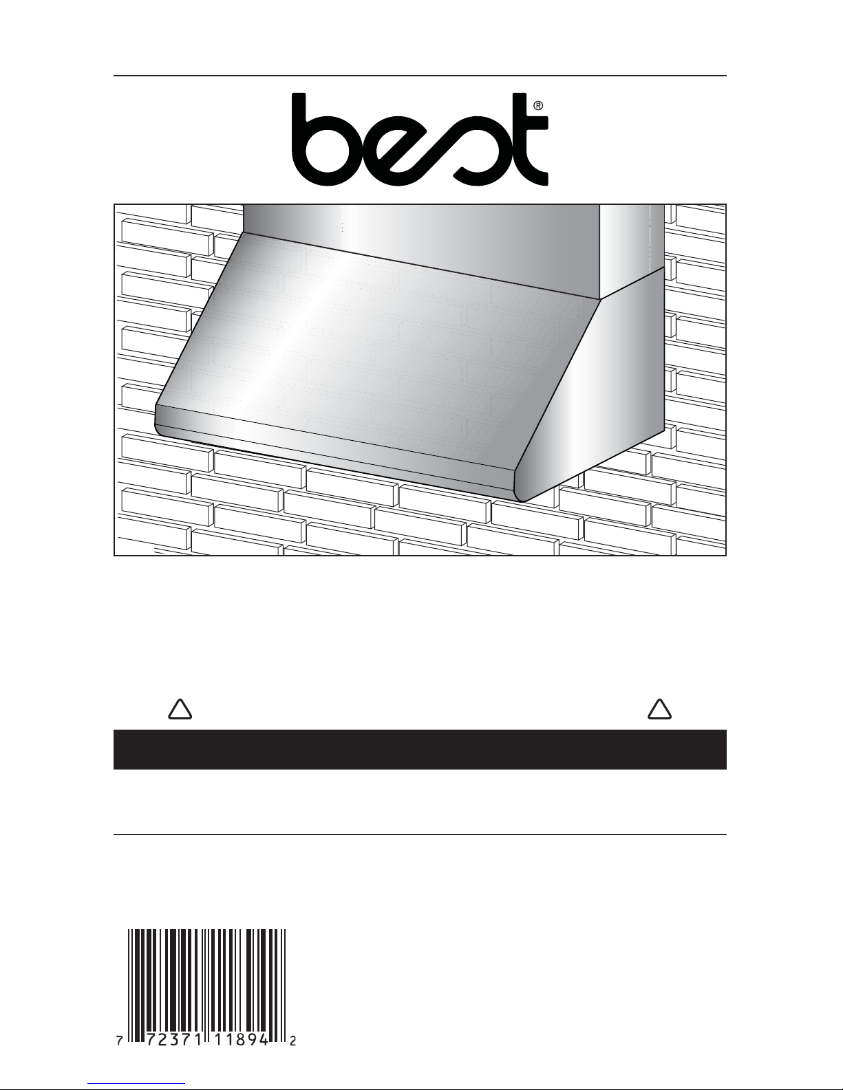
WPD38 SERIES
INTENDED FOR DOMESTIC COOKING ONLY
INSTALLER: LEAVE THIS MANUAL WITH HOMEOWNER.
HOMEOWNER: USE AND CARE INFORMATION ON PAGES 9
AND 10.
READ AND SAVE THESE INSTRUCTIONS
!
!
INSTALLATION INSTRUCTIONS
SUITABLE FOR USE IN DAMP LOCATIONS WHEN INSTALLED IN A
GFCI PROTECTED BRANCH-CIRCUIT.
I
NTENDED FOR OUTDOOR COVERED PATIO OR LANAI AREA.
BEST; Hartford, Wisconsin www.BestRangeHoods.com 800-558-1711
BEST; Drummondville, QC, Canada www.BestRangeHoods.com 866-737-7770
REGISTER YOUR PRODUCT ON LINE AT: www.BestRangeHoods.com/register
For additional information - visit www.BestRangeHoods.com
HB0113
Page 2

WARNING
TO REDUCE THE RISK OF FIRE, ELECTRIC
SHOCK OR INJURY TO PERSONS, OBSERVE
THE FOLLOWING:
1. Use this unit only in the manner intended by the
manufacturer. If you have questions, contact the
manufacturer at the address or telephone number
listed in the warranty.
2. Before servicing or cleaning unit, switch power off
at service panel and lock service disconnecting
means to prevent power from being switched on
accidentally. When the service disconnecting
means cannot be locked, securely fasten a prominent
warning device, such as a tag, to the service panel.
3. Installation work and electrical wiring must be done
by qualified personnel in accordance with all
applicable codes and standards, including
fire-rated construction codes and standards.
4. Sufficient air is needed for proper combustion and
exhausting of gases through the flue (chimney) of
fuel burning equipment to prevent backdrafting.
Follow the heating equipment manufacturer’s
guidelines and safety standards such as those
published by the National Fire Protection
Association (NFPA), and the American Society for
Heating, Refrigeration and Air Conditioning
Engineers (ASHRAE), and the local code authorities.
5. When cutting or drilling into wall or ceiling, do not
damage electrical wiring and other hidden utilities.
6. Ducted fans must always be vented to the outdoors.
7. Do not use this unit with any additional solid-state
speed control device.
8. To reduce the risk of fire, use only metal ductwork.
9. This unit must be grounded and protected by a
GFCI.
10.
Suitable for use in damp locations only when installed
in a GFCI PROTECTED branch-circuit.
11.
This unit is not designed to be used with a charcoal
grill.
12. When applicable local regulations comprise more
restrictive installation and/or certification
requirements, the aforementioned requirements
prevail on those of this document and the installer
agrees to conform to these at his own expenses.
TO REDUCE THE RISK OF A RANGE TOP
GREASE FIRE:
a) Never leave surface units unattended at high
settings. Boilovers cause smoking and greasy
spillovers that may ignite. Heat oils slowly on low or
medium settings.
b) Always turn hood ON when cooking at high heat or
when flambeing food (i.e.: Crêpes Suzette,
Cherries Jubilee, Peppercorn Beef Flambé).
c) Clean ventilating fans frequently. Grease should
not be allowed to accumulate on fans, filters or
exhaust ducts.
d) Use proper pan size. Always use cookware
appropriate for the size of the surface element.
!
WARNING
TO REDUCE THE RISK OF INJURY TO PERSONS
IN THE EVENT OF A RANGE TOP GREASE
FIRE, OBSERVE THE FOLLOWING*:
1. SMOTHER FLAMES with a close-fitting lid,
cookie sheet or metal tray, then turn off the burner.
BE CAREFUL TO PREVENT BURNS. IF THE
FLAMES DO NOT GO OUT IMMEDIATELY,
EVACUATE AND CALL THE FIRE DEPARTMENT.
2. NEVER PICK UP A FLAMING PAN – You may be
burned.
3. DO NOT USE WATER, including wet dishcloths
or towels – This could cause a violent steam
explosion.
4. Use an extinguisher ONLY if:
A. You own a Class ABC extinguisher and you
know how to operate it.
B. The fire is small and contained in the area
where it started.
C. The fire department has been called.
D. You can fight the fire with your back to an exit.
*Based on “Kitchen Fire Safety Tips” published by NFPA.
!
- 2 -
CAUTION
1. For general ventilating use only. Do not use to
exhaust hazardous or explosive materials and
vapors.
2. To avoid motor bearing damage and noisy and/or
unbalanced impellers, keep drywall spray,
construction dust, etc. off power unit.
3. Your hood motor has a thermal overload which will
automatically shut off the motor if it becomes
overheated. The motor will restart when it will be
cooled down. If the motor continues to shut off and
restart, have the hood serviced.
4. For best capture of cooking impurities, the bottom
of the hood must be located at a minimum distance
of 36" above cooking surface.
5. Two installers are recommended because of the
large size and weight of this hood.
6. To reduce the risk of fire and to properly exhaust
air, be sure to duct air outside—Do not exhaust air
into spaces within walls or ceiling or into attics,
crawl space or garage.
7. This product is equipped with a thermostat which
may start blower automatically. To reduce the risk
of injury and to prevent power from being switched
on accidentally, switch power off at service panel
and lock or tag service panel.
8. Please read specification label on product for
further information and requirements.
Page 3
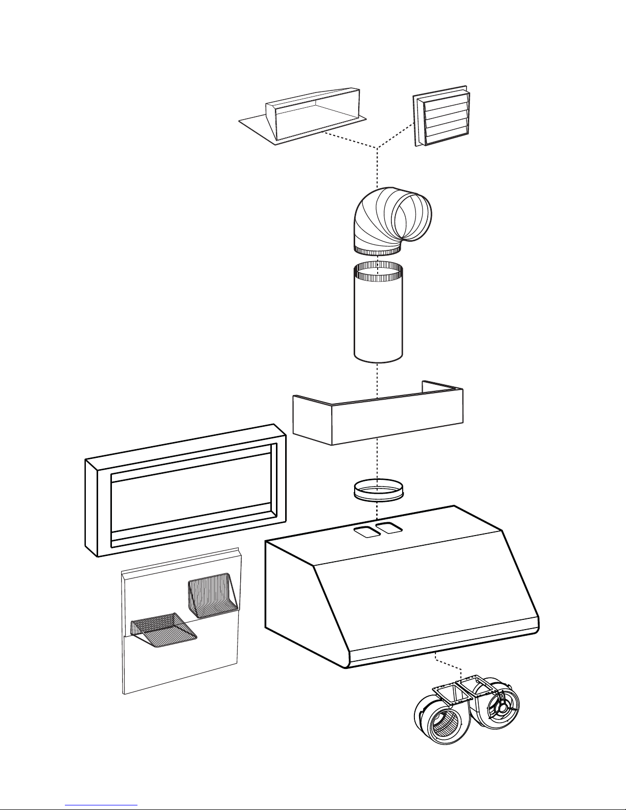
- WPD38 SERIES RANGE HOOD SYSTEM -
- 3 -
HL0184
MODEL 437
(H
IGH CAPACITY ROOF CAP)
M
ODEL 441
(10’’ R
OUND WALL CAP)
M
ODEL 410
(10” ROUND DUCT
— 2 FT. SECTIONS)
M
ODEL 418
(10” ROUND
ADJUSTABLE ELBOW)
D
UAL BLOWER
1200 CFM
(INCLUDED)
10” R
OUND ADAPTER
(INCLUDED)
OPTIONAL
DECORATIVE FLUE
AEWPD SERIES
WPD38 SERIES
RANGE HOOD
OPTIONAL BACKSPLASH
ABWPD SERIES
36"
OR 48" WIDTH
(STAINLESS STEEL WALL COVERING
WITH WARMING SHELVES)
OPTIONAL
WALL EXTENSION
AWWPD SERIES
Page 4
- 4 -
1. INSTALL DUCTWORK AND ELECTRICAL WIRING
Plan where and how the ductwork will be installed.
A straight, short duct run will allow the hood to
perform most efficiently.
Install proper-sized ductwork, elbows and roof or wall
cap. Connect metal ductwork to cap and work back
towards the hood location. Use 2” metal foil duct tape
to seal the joints.
Run 3-wire power supply cable to installation location.
For best capture of cooking impurities, the bottom
of the hood must be located at a minimum
distance of 36" above cooking surface.
18"
WALL CAP
36" MINIMUM ABOVE
COOKING
SURFACE
16" TO
TOP
OF WOOD
MOUNTING
STRIP
OPTIONAL DECORATIVE
FLUE OR SOFFIT
HH0181A
ROOF CAP
10" ROUND DUCT
10" ROUND ELBOW
10" ROUND
ADAPTER
The power cable must be a GFCI protected
branch circuit.
WARNING
!
Make sure that the following items are included:
- Range hood
- Wood strip (attached to back of hood)
- Installation manual
- Accessories including:
• Baffle filters: 3 for 36” width model, 4 for 48” width model and 5 for 60” width model
• Baffle filters handles (taped inside the hood)
• Shielded halogen bulbs (120 V, 50 W max., MR16 with GU10 base) (2 for 36” width hood, 3 for
48” and 60” width hoods)
• 10” round adapter (taped inside the hood)
• Bag of parts: 3 waterproof wire connectors, 2 wire clamps LP16-AP, 8 no. 8 x 5/8’’ screws,
2 no. 8 x 3/8’’ zinc-plated screws, 8 no. 8 x 3/8’’ screws, 4 no. 10 x 2” flat head screws,
10 no. 8-32 x 3/8” screws, 2 wall anchors, 2 washers 3/16’’ ID x 3/4’’ OD
2. PREPARE INSTALLATION
NOTE: Before proceeding to the installation, check the contents of the box. If items are missing or
damaged, contact the manufacturer.
When performing installation, servicing or cleaning the unit, it is recommended
to wear safety glasses and gloves.
WARNING
!
This range hood is not designed for use with a charcoal grill.
WARNING
!
This range hood is intended for outdoor covered patio or lanai area. As with all electric appliances,
this unit should be protected from the effects of weather as much as possible.
Page 5
4. INSTALL WALL EXTENSION (OPTIONAL)
AWWPD Series
Wall extension must be installed before the hood (see instructions packed with wall extension).
- 5 -
3. INSTALL BACKSPLASH (OPTIONAL)
ABWPD Series
(for 36” and 48” widths range hoods only)
Backsplash must be installed before
the hood shell because the hood shell covers the backsplash
top mounting screws (see instructions packed with backsplash).
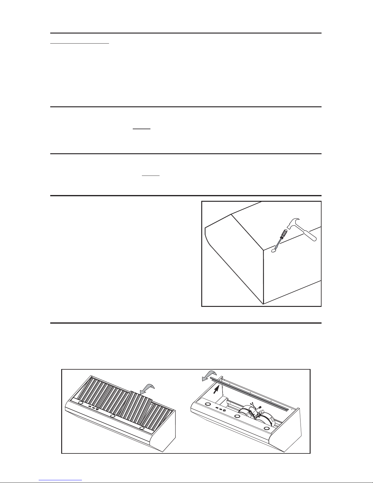
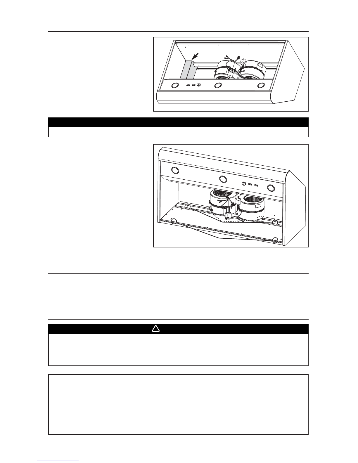
5. REMOVE KNOCKOUT OPENING
Punch out the electrical knockout hole on the back of
the hood. Install the wire clamp (included in parts
bag).
HR0072
6. REMOVE BAFFLE FILTERS AND GREASE DRIP RAIL
A. Remove tape on filters.
Remove filters from hood and set aside.
NOTE: It is recommended to start with the center one(s).
B. Remove tape on grease drip rail (1).
Lift out grease drip rail and set aside.
HD0462
1
AB
2. PREPARE INSTALLATION (CONT’D)
Parts sold separately:
- ABWPD Series Backsplash, 36” or 48” width (optional)
- AEWPD Series Decorative flue, to be installed over the hood (optional)
- AWWPD Series Wall extension, 36”, 48” or 60” width (optional)
- Transitions, duct, elbows, dampers, wall and roof caps
Refer to page 3 for a complete list of venting options and model numbers.
NOTE: During installation, protect countertop and/or cooktop.
Page 6

7. INSTALL ADAPTER
Remove adapter from inside hood.
Using both no. 8 x 3/8” zinc-plated screws from parts
bag, assemble the adapter on the top of the hood.
Seal all joints with metal foil duct tape to eliminate air
leaks.
- 6 -
1. Wall
2. Wood mounting strip
3. Flat head screw
4. Wall anchor location
5. Back of hood outline
6. Wall studs
8. INSTALL WOOD MOUNTING STRIP (IF NOT USING WALL EXTENSION)
NOTE: If range hood is installed with optional wall extension,
refer to the instructions sheet included with the
wall extension for wood mounting strip location.
Measure and mark a level line on wall above cooktop
location for the wood mounting strip (see illustration on
page 4). Remove wood mounting strip from back of hood.
Center wood mounting strip over location (see illustration
at right).
Use no. 10 x 2’’ flat head screws to secure the mounting
strip to the wall.
Make sure to hit the wall studs.
HD0478A
Due to the weight of this hood, ensure that the wood strip is attached to all of
the available studs (2 studs minimum for 36" width hood and 3 studs minimum
for 48" or 60" width hood); not into the wall alone.
CAUTION
HJ0069
MOUNTING SCREWS LOCATION
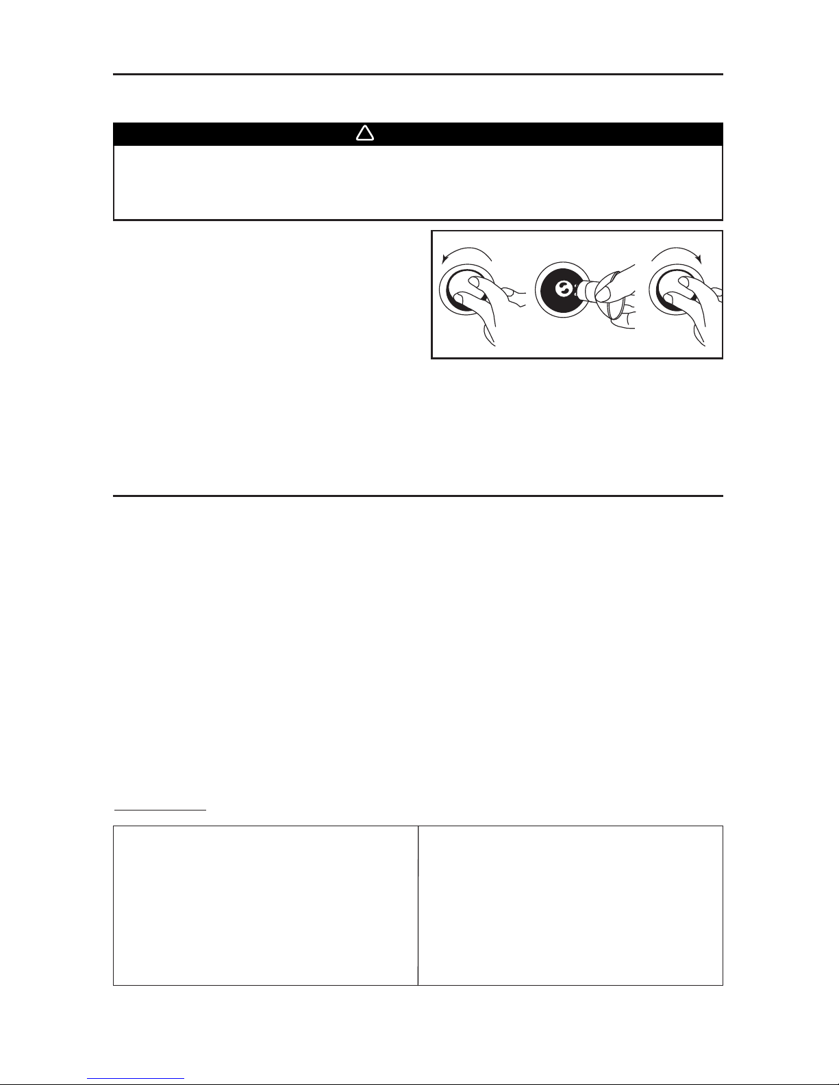
9. INSTALL HOOD
At the end of installation, the following
areas should have been sealed to prevent
water infiltration:
•
Around adapter (1)
• Between wall and hood (2)
• 4 holes on top of the hood (if not installing optional
decorative flue) (3)
CAUTION
HD0477
2
3
1
Page 7
- 7 -
Remove the electrical compartment
cover. Insert the house wiring in the
hood and tighten the wire clamp to
secure the wiring.
9. INSTALL HOOD (CONT’D)
HD0464
ELECTRICAL COMPARTMENT COVER
Hold the hood until it is completely secured to the wood mounting strip.
CAUTION
Rest the back cavity of the hood on
the wood mounting strip.
Attach 10” round duct to adapter.
Secure the hood to wood mounting
strip with 4 screws no. 8 x 5/8’’ (for 36’’
width hood) or 6 screws (for 48’’ and
60’’ width hoods) provided at locations
shown. Drill two 3/16’’ diameter holes
into the wall for wall anchors through
the existing holes in the inside hood
back in the locations shown. Then,
install both wall anchors with the
remaining no. 8 x 5/8’’ screws and
both washers provided.
HD0463
MOUNTING SCREWS LOCATION
W
ALL ANCHORS LOCATION
11. CONNECT WIRING
Risk of electric shock. Electrical wiring must be done by qualified personnel in
accordance with all applicable codes and standards. Before connecting wires,
switch power off at service panel and lock service disconnecting means to
prevent power to be switched on accidentally.
WARNING
!
WATERPROOF WIRE CONNECTORS INSTRUCTIONS:
1. Strip wires 3/8’’.
2. Align frayed strands or conductors.
3. Do not pre-twist. Place stripped wires together with ends even, but lead smaller stranded wires
slightly ahead of larger solid or stranded wire.
4. Twist connector onto wires pushing firmly until hand-tight. DO NOT over torque.
5. When inserting wires into connectors, some sealant may leak out. Wipe off excess sealant in
and around conductors. DO NOT REUSE.
10. INSTALL DECORATIVE FLUE (OPTIONAL)
AEWPD Series
Refer to the instructions included with the optional decorative flue.
Page 8

- 8 -
Connect cable into electrical compartment
using provided waterproof wire connectors.
Connect BLACK to BLACK, WHITE to WHITE
and GREEN or bare wire under ground screw.
Reinstall electrical compartment cover.
HE0138
Reinstall grease drip rail. The illustration at right
shows how to reinsert the grease drip rail into the
range hood.
12. REINSTALL GREASE DRIP RAIL AND BAFFLE FILTERS
HD0465
Remove protective plastic film covering filters before installing them.
CAUTION
11. CONNECT WIRING (CONT’D)
NOTE: Assemble the metal handles to the filters, using provided no. 8-32 x 3/8” screws, before
installing them in the hood.
It is recommended to install side filters first and finish with center one(s).
1. Insert one end of the filter into the upper channel of the hood.
2. Raise the other end toward the inside of hood and insert in the grease drip rail of the hood.
1
HD0466
2
Page 9
- 9 -
1. To remove lamps, gently push upwards and turn
counterclockwise to disengage bulb leads from
their grooves.
NOTE: To ease removal of the bulbs, use a rubber
dishwashing glove or use suction cup tool
available from Best. Contact Best
Technical Support at 1-800-558-1711 to
order suction cup tool, part no. 99526707.
2. Install the new lamps by placing the bulb leads into their grooves in the socket.
3. Gently push upwards and turn clockwise until secure.
13. LIGHT BULBS REPLACEMENT
This hood requires 120 V, 50 W, MR16 with GU10 base, shielded halogen lamps (included). (2 for
36” width hood, 3 for 48” and 60” width hoods.)
Do not touch lamps during or soon after operation. Burns may occur. In order to
prevent the risk of personal injury, only install shielded halogen lamps. Also,
never install a cool beam, a dichroïc lamp, a lamp not suitable for use in
recessed luminaires or identified for use in enclosed fixtures.
WARNING
!
14. CARE
Baffle Filters
The baffle filters should be cleaned frequently. Use a warm detergent solution. Wash more often
if your cooking style generates greater grease like frying foods or wok cooking.
Remove baffle filters by pushing them towards the front of the hood and rotating filters downward.
Baffle filters are dishwasher safe. Allow filters to dry completely before reinstalling them in the hood.
Clean all-metal filters in the dishwasher using a non-phosphate detergent. Discoloration of the
filter may occur if using phosphate detergent or as a result of local water conditions—but this will
not affect filter performance. This discoloration is not covered by the warranty.
12 3
HO0089
Grease Drip Rail
The grease drip rail should be cleaned frequently. Lift it out from the hood and use a warm detergent
solution. As for the baffle filters, wash more often if your cooking style generates greater grease
like frying foods or wok cooking. Allow grease drip rail to dry completely before reinstalling it in the
hood.
Blowers Cleaning
Remove the filters in order to access the blowers. Vacuum blowers to clean. Do not immerse in
water.
Hood Cleaning
Stainless steel:
Do:
• Regularly wash with clean cloth or rag
soaked with warm water and mild soap or
liquid dish detergent.
• Always clean in the direction of original polish
lines.
• Always rinse well with clear water (2 or 3
times) after cleaning. Wipe dry completely.
• You may also use a specialized household
stainless steel cleaner.
Don’t:
• Use any steel or stainless steel wool or any
other scrapers to remove stubborn dirt.
• Use any harsh or abrasive cleansers.
• Allow dirt to accumulate.
• Let plaster dust or any other construction
residues reach the hood. During construction/
renovation, cover the hood to make sure no
dust sticks to stainless steel surface.
Page 10
- 10 -
14. CARE (CONT’D)
Avoid when choosing a detergent:
• Any cleaners that contain bleach will attack stainless steel.
• Any products containing: chloride, fluoride, iodide, bromide will deteriorate surfaces rapidly.
• Any combustible products used for cleaning such as acetone, alcohol, ether, benzol, etc., are
highly explosive and should never be used close to a range.
BLOWER
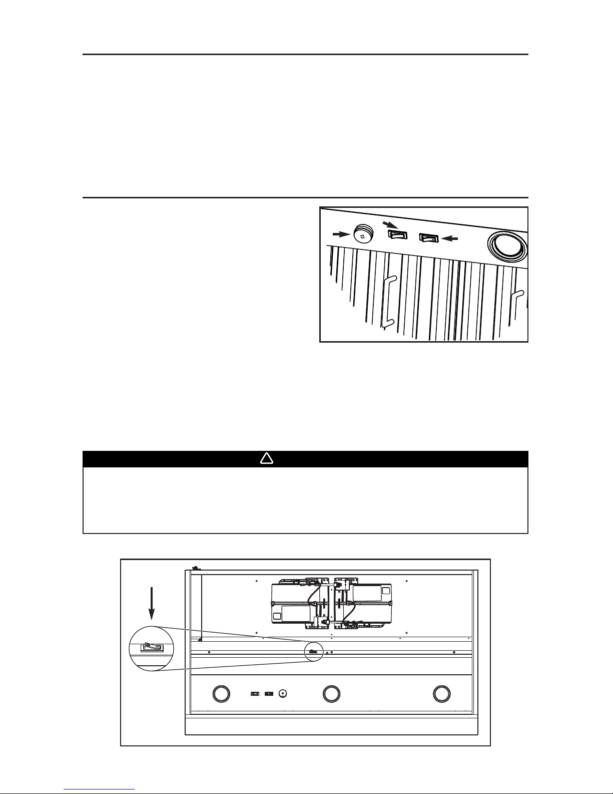
The blower is operated using two controls.
Use the on/off rocker switch (2) to start and stop
the blower. When turned ON, the switch turns red
and the blower operates at the speed set by the
speed control knob (1).
Turn the speed control knob clockwise to increase
blower speed – counterclockwise to decrease
speed.
COOKTOP LIGHTING (HALOGEN)
Use the on/off rocker switch (3) to turn the halogen
lights ON or OFF.
15. OPERATION
1) B
LOWER SPEED CONTROL KNOB
2) ON/OFF
BLOWER SWITCH
3) H
ALOGEN LIGHT SWITCH
HEAT SENTRY™
This hood is equipped with a Heat Sentry™ thermostat. This thermostat is a device that will turn
on the blower if it senses excessive heat above the cooking surface.
1) If blower is OFF - it turns blower ON to the last selected speed.
2) If blower is already ON speed will remain the same.
When the temperature level drops to normal, the blower will return to its original setting.
The HEAT SENTRY can start the blower during a range top fire or other excessive
heat situations even if the hood is turned off. In this case, it is impossible to turn
the blower OFF using control panel switch. To stop the blower, set the main
power switch located behind the baffle filters in OFF position, if it is possible to
do safely.
WARNING
!
HD0467
MAIN POWER
SWITCH
HC0058
2
3
1
Page 11
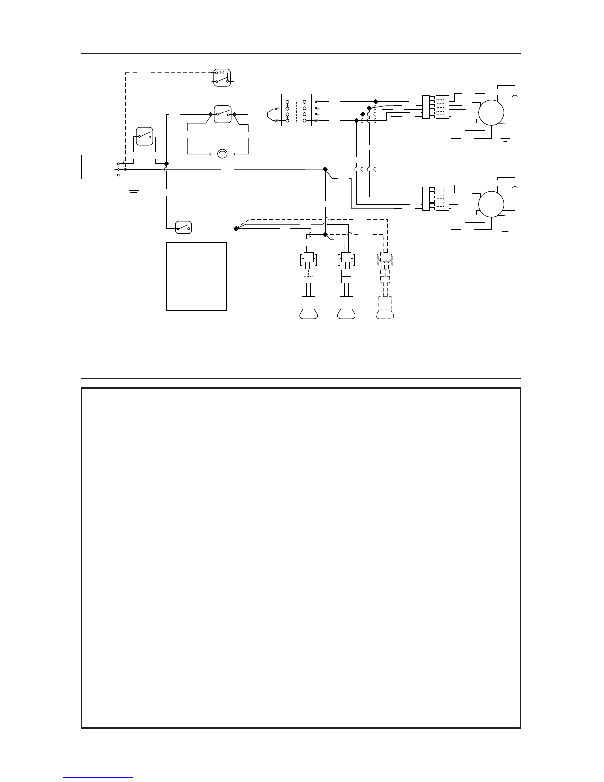
- 11 -
LINE
NEUTRAL
GROUND
120 VAC
LAMP
LAMP
SWITCH
LAMP
LAMP
COLOR CODE
HE0136A
BLK BLACK
BLU BLUE
BRN BROWN
GRY GREY
ORA ORANGE
RED RED
WHT WHITE
YEL YELLOW
WHT
WHT
WHT
WHT
WHT
WHT
WHT
YEL
YEL
YEL
BLK
BLK BLK
MAIN
SWITCH
FAN SWITCH
FAN SWITCH
OR
RED RED
HEAT SENTRY
THERMOSTAT
GRY
GRY
BLU
WHT
ORA
BLK
A
B
1
2
3
4
BLU
WHT
WHT
ORA
BLK
BLU
WHT
ORA
BLK
WHT
M
M
BLU
WHT
ORA
BLK
RED
GRY
BRN
BLU
WHT
WHT
ORA
BLK
BLU
WHT
ORA
BLK
RED
GRY
BRN
YEL
BLK
16. WIRING DIAGRAM
17. WARRANTY
ONE-YEAR LIMITED WARRANTY FOR BEST PRODUCTS
Broan-NuTone LLC (Broan-NuTone) warrants to the original consumer purchaser of Best products that such
products will be free from defects in materials or workmanship for a period of one year from the date of original
purchase. THERE ARE NO OTHER WARRANTIES, EXPRESS OR IMPLIED, INCLUDING, BUT NOT LIMITED
TO, IMPLIED WARRANTIES OR MERCHANTABILITY OR FITNESS FOR A PARTICULAR PURPOSE.
During this one-year period, Broan-NuTone will, at its option, repair or replace, without charge, any product or
part which is found to be defective under normal use and service.
THIS WARRANTY DOES NOT EXTEND TO FLUORESCENT LAMP STARTERS, TUBES, HALOGEN AND
INCANDESCENT BULBS, FUSES, FILTERS, DUCTS, ROOF CAPS, WALL CAPS AND OTHER ACCESSORIES
FOR DUCTING. This warranty does not cover (a) normal maintenance and service or (b) any products or parts
which have been subject to misuse, negligence, accident, improper maintenance or repair (other than by
Broan-NuTone), faulty installation or installation contrary to recommended installation instructions.
The duration of any implied warranty is limited to the one-year period as specified for the express warranty.
Some states or provinces do not allow limitation on how long an implied warranty lasts, so the above limitation
may not apply to you.
BROAN-NUTONE’S OBLIGATION TO REPAIR OR REPLACE, AT BROAN-NUTONE’S OPTION, SHALL BE
THE PURCHASER’S SOLE AND EXCLUSIVE REMEDY UNDER THIS WARRANTY. BROAN-NUTONE
SHALL NOT BE LIABLE FOR INCIDENTAL, CONSEQUENTIAL OR SPECIAL DAMAGES ARISING OUT
OF OR IN CONNECTION WITH PRODUCT USE OR PERFORMANCE. Some states or provinces do not
allow the exclusion or limitation of incidental or consequential damages, so the above limitation or
exclusion may not apply to you.
This warranty gives you specific legal rights, and you may also have other rights, which vary from state to state
or province to another. This warranty supersedes all prior warranties.
To qualify for warranty service, you must (a) notify Broan-NuTone at the address or telephone number stated
below, (b) give the model number and part identification and (c) describe the nature of any defect in the product
or part. At the time of requesting warranty service, you must present evidence of the original purchase date.
In USA - Best
®
;
926 W. State Street, Hartford, WI 53027 (800-558-1711)
In Canada - Best
®
;
550 Lemire Blvd., Drummondville, QC, Canada, J2C 7W9 (866-737-7770)
www.BestRangeHoods.com
Page 12

HL0185
- 12 -
18. SERVICE PARTS
1
2
3
4
6
7
8
11
12
13
10
9
5
*NOT SHOWN.
KEY
NO
.
PART NO. DESCRIPTION
QTY. (RANGE HOOD WIDTH)
36” 48” 60”
1 SV08541 10” ROUND ADAPTER 1 1 1
2 SV16569 LIGHT SOCKET AND TRIM ASSEMBLY 2 3 3
3 SV05921 SHIELDED HALOGEN BULB (120 V, 50 W, GU10 BASE) 2 3 3
4 SV08582 BLOWER 2 2 2
5 SV08337 FILTER SPRING 3 4 5
6 SV60675 BAFFLE FILTER 11.84” X 15.125” (INCLUDING SPRING) 3 4 5
7
SV60695
SV60696
SV60697
GREASE RAIL 36”
GREASE RAIL 48”
G
REASE RAIL 60”
1
-
-
-
1
-
-
-
1
8 SV18058 BAFFLE FILTER HANDLE WITH SCREWS 3 4 5
9 SV02563 LIGHT ROCKER SWITCH 1 1 1
10 SV03503 BLOWER ROCKER SWITCH 1 1 1
11 SV08549 FAN KNOB 1 1 1
12 SV03435 HEAT SENTRY™ THERMOSTAT 1 1 1
13 SV08968 SPEED CONTROL 1 1 1
14 SV08548 MAIN POWER SWITCH 1 1 1
* SV05869 BEST LOGO 1 1 1
* SV20569 INSTALLATION GUIDE 1 1 1
* SV06934
PARTS BAG: 3 WATERPROOF WIRE CONNECTORS,
2
WIRE CLAMPS LP16-AP, 8 NO. 8 X 5/8’’ SCREWS,
2 NO. 8 X 3/8’’ ZINC-PLATED SCREWS, 8 NO. 8 X 3/8’’ SCREWS,
4 NO. 10 X 2” FLAT HEAD SCREWS, 10 NO. 8-32 X 3/8” SCREWS,
2 WALL ANCHORS, 2 WASHERS 3/16’’ ID X 3/4’’ OD
1 1 1
REPLACEMENT PARTS AND REPAIRS
In order to ensure your ventilation unit
remains in good working condition, you
must use Broan-NuTone genuine
replacement parts only. Broan-NuTone
genuine replacement parts are specially
designed for each unit and are
manufactured to comply with all the
applicable certification standards and
maintain a high standard of safety. Any
third party replacement part used may
cause serious damage and drastically
reduce the performance level of your
unit, which will result in premature
failing. Broan-NuTone recommends to
contact a certified service depot for all
replacement parts and repairs.
14
Page 13

SV20569 rév. 01
SÉRIE WPD38
CONÇUE POUR UN USAGE DOMESTIQUE SEULEMENT
INSTALLATEUR : LAISSER CE MANUEL AU PROPRIÉTAIRE.
PROPRIÉTAIRE : DIRECTIVES D’UTILISATION ET D’ENTRETIEN
AUX PAGES 21
ET 22.
LIRE ET CONSERVER CES DIRECTIVES
!
!
GUIDE D’INSTALLATION
CONVIENT À UNE INSTALLATION DANS DES LIEUX HUMIDES
LORSQU
’ELLE EST RACCORDÉE À UN
DISJONCTEUR DE FUITE À LA TERRE (DDFT).
C
ONÇUE POUR FONCTIONNER SUR UN PATIO COUVERT OU UNE VÉRANDA.
BEST; Hartford, Wisconsin www.BestRangeHoods.com 800 558-1711
BEST; Drummondville, QC, Canada www.BestRangeHoods.com 866 737-7770
ENREGISTREZ VOTRE PRODUIT EN LIGNE À : www.BestRangeHoods.com/register
Pour obtenir plus d’information, consultez notre site www.BestRangeHoods.com
HB0113
Page 14

AVERTISSEMENT
AFIN DE RÉDUIRE LES RISQUES
D’INCENDIE, D’ÉLECTROCUTION OU DE
BLESSURES CORPORELLES, SUIVEZ LES
DIRECTIVES SUIVANTES :
1. N’utilisez cet appareil que de la façon prévue par
le manufacturier. Si vous avez des questions,
contactez le manufacturier à l’adresse ou au
numéro de téléphone indiqués dans la garantie.
2. Avant de réparer ou de nettoyer l’appareil, coupez
l’alimentation électrique en verrouillant le panneau
de distribution afin d’éviter sa remise en marche
accidentelle. Si le panneau de distribution ne peut
être verrouillé, y fixer un avertissement en
évidence, telle qu’une étiquette de couleur vive.
3. Les travaux d’installation et de raccordement
électrique doivent être effectués par du personnel
qualifié, conformément aux codes et aux standards
de construction, incluant ceux concernant la
protection contre les incendies.
4. Une quantité d’air adéquate est requise afin
d’assurer une bonne combustion et l’évacuation
des gaz par la cheminée dans le cas des
équipements alimentés au gaz afin de prévenir les
retours de cheminée. Conformez-vous aux instructions
et aux standards de sécurité des manufacturiers
d’équipement de chauffage, tels qu’ils sont publiés
par la
National Fire Protection Association
(NFPA)
et l’
American Society for Heating, Refrigeration and
Air Conditioning Engineers
(ASHRAE) ainsi que les
responsables des codes locaux.
5. Lorsque vous coupez ou perforez un mur ou un
plafond, prenez garde de ne pas endommager
les fils électriques ou autre installation qui
pourraient y être dissimulés.
6. Les ventilateurs avec conduits doivent toujours
évacuer l’air à l’extérieur.
7. Ne pas utiliser cet appareil avec une commande de
vitesse à semi-conducteur additionnelle.
8. Afin de réduire les risques d’incendie, n’utilisez que
des conduits de métal.
9. Cet appareil doit être mis à la terre et protégé par
un DDFT (disjoncteur de fuite à la terre).
10.
Convient à une utilisation dans des lieux humides
seulement lorsqu’elle est raccordée à un
DISJONCTEUR DE FUITE À LA TERRE (DDFT).
11.
Cet appareil n’est pas conçu pour être utilisé avec un
barbecue au charbon de bois.
12. Lorsqu’une réglementation est en vigueur localement
et qu’elle comporte des exigences d’installation
et/ou de certification plus restrictives, lesdites
exigences prévalent sur celles de ce document et
l’installateur entend s’y conformer à ses frais.
AFIN DE RÉDUIRE LES RISQUES DE FEU
DE CUISINIÈRE :
a) Ne laissez jamais les appareils de cuisson sans
surveillance lorsqu’ils sont réglés à feu vif. Les
débordements engendrent de la fumée et des
déversements graisseux pouvant s’enflammer.
Chauffez l’huile lentement, à feu doux ou moyen.
b) Mettez toujours la hotte en marche lorsque vous
cuisinez à feu vif ou que vous cuisinez des
mets flambés (crêpes Suzette, cerises jubilé,
steaks au poivre flambés).
c) Nettoyez régulièrement la (les) roue(s) du ventilateur.
Ne laissez pas la graisse s’accumuler sur le
ventilateur, les filtres ou les conduits d’évacuation.
d) Utilisez le bon format de casserole. Servez-vous
toujours de casseroles et d’ustensiles appropriés à
la dimension de la surface chauffante.
!
AVERTISSEMENT
AFIN D’ÉVITER TOUT RISQUE DE
BLESSURES DANS LE CAS D’UN FEU DE
CUISINIÈRE, SUIVEZ CES DIRECTIVES* :
1. Étouffez les flammes avec un couvercle hermétique,
une tôle à biscuits ou un plateau métallique et
ensuite, éteindre le brûleur. PRENEZ SOIN
D’ÉVITER LES BRÛLURES. SI LES FLAMMES
NE S’ÉTEIGNENT PAS IMMÉDIATEMENT, ÉVACUEZ
LES LIEUX ET APPELEZ LES POMPIERS.
2. NE PRENEZ JAMAIS UNE CASSEROLE EN
FLAMMES DANS VOS MAINS. Vous pourriez
vous brûler.
3. N’UTILISEZ PAS D’EAU, incluant linge à vaisselle
ou serviette mouillés; ceci pourrait occasionner une
violente explosion de vapeur.
4. N’utilisez un extincteur QUE DANS LE CAS OÙ:
A. Vous savez qu’il s’agit d’un extincteur de classe
ABC et que vous en connaissez le fonctionnement.
B. L’incendie est petit et limité à l’endroit où il
a débuté.
C. Les pompiers ont été avisés.
D. Vous pouvez combattre l’incendie en ayant
accès à une sortie de secours.
*Tirées du
Kitchen Fire Safety Tips
publié par la NFPA.
!
- 14 -
ATTENTION
1. Pour usage domestique seulement. Ne l’utilisez pas
pour évacuer des vapeurs ou des matières
dangereuses ou explosives.
2. Afin d’éviter tout dommage au moteur et de débalancer
ou de rendre bruyante la roue du moteur, gardez
votre appareil à l’abri des poussières de gypse et
de construction/rénovation, etc.
3. Le moteur de votre hotte possède une protection
thermique qui arrêtera automatiquement le
fonctionnement du moteur s’il devient surchauffé.
Le moteur redémarrera automatiquement une fois
refroidi. Si le moteur continue à arrêter et à
redémarrer, faites-le vérifier.
4. Pour une meilleure évacuation des odeurs de
cuisson, le bas de votre hotte doit être situé à une
distance minimale de 36 po au-dessus de la
surface de cuisson.
5. Deux installateurs sont recommandés lors de
l’installation vu la grande dimension et le poids de
cette hotte.
6. Afin de réduire les risques d’incendie, assurez-vous
d’évacuer l’air à l’extérieur. Ne pas évacuer l’air
dans des espaces restreints comme l’intérieur des
murs ou plafond ou dans le grenier, faux plafond
ou garage.
7. Cet appareil est équipé d’un thermostat pouvant
faire démarrer le ventilateur automatiquement. Afin
de réduire les risques de blessures, couper le
courant à partir du panneau de distribution et
verrouiller ou apposer un avertissement sur le
panneau afin de prévenir que la hotte soit mise en
marche accidentellement.
8. Veuillez consulter l’autocollant apposé à l’intérieur de
la hotte pour plus d’information ou autres exigences.
Page 15

- SYSTÈME DE HOTTE DE CUISINIÈRE SÉRIE WPD38 -
HL0184
MODÈLE 437
(C
APUCHON DE TOIT À
HAUT RENDEMENT
)
M
ODÈLE 441
(C
APUCHON MURAL 10 PO ROND)
M
ODÈLE 418
(COUDE AJUSTABLE
DE 10 PO ROND)
V
ENTILATEUR
DOUBLE
1200 PCM
(INCLUS)
A
DAPTATEUR ROND DE 10 PO
(INCLUS)
CHEMINÉE DÉCORATIVE
OPTIONNELLE
SÉRIE AEWPD
HOTTE
SÉRIE WPD38
- 15 -
DOSSERET OPTIONNEL
SÉRIE ABWPD
LARGEUR DE 36 PO OU 48 PO
(RECOUVREMENT DE MUR EN
ACIER INOXYDABLE AVEC
SUPPORT ASSIETTES)
RALLONGE DE HOTTE
OPTIONNELLE
SÉRIE AWWPD
M
ODÈLE 410
(CONDUIT 10 PO ROND,
SECTIONS 2 PI)
Page 16

- 16 -
1. INSTALLER LES CONDUITS ET LE CÂBLAGE ÉLECTRIQUE
Déterminer à quel endroit et comment les conduits
seront installés.
Un conduit droit et court permettra à votre hotte de
fonctionner plus efficacement.
Installer des conduits de dimensions adéquates, des
coudes et un capuchon de toit ou de mur. Relier le
conduit de métal au capuchon, puis acheminer le conduit
jusqu’à l’emplacement de votre hotte. Sceller les joints
avec du ruban adhésif de métal de 2 po de largeur.
Acheminer un câble d’alimentation électrique à
3 conducteurs jusqu’à l’emplacement de la hotte.
Pour une meilleure évacuation des odeurs de
cuisson, le bas de votre hotte doit être situé à une
distance minimale de 36 po au-dessus de la
surface de cuisson.
18 PO
CAPUCHON
MURAL
MINIMUM DE 36 PO
AU-DESSUS DE LA
SURFACE DE CUISSON
DISTANCE DE
16 PO JUSQU’AU
DESSUS
DE LA
LISIÈRE
DE BOIS
CHEMINÉE DÉCORATIVE
OPTIONNELLE
OU SOFFITE
HH0181F
CAPUCHON DE TOIT
CONDUIT ROND DE 10 PO
COUDE ROND DE 10 PO
ADAPTATEUR
10
PO ROND
Le fil d’alimentation électrique doit être raccordé
à un disjoncteur de fuite à la terre (DDFT).
AVERTISSEMENT
!
Cette hotte n’est pas conçue pour être utilisée avec un barbecue au charbon de bois.
AVERTISSEMENT
!
S’assurer que les articles suivants soient inclus :
- Hotte
- Lisière de bois (fixée au dos de la hotte)
- Guide d’installation
- Les accessoires incluant :
• Filtres à chicane : 3 pour le modèle de 36 po de largeur, 4 pour le modèle de 48 po de largeur
et 5 pour le modèle de 60 po de largeur
• Poignées des filtres à chicane (fixées avec du ruban adhésif à l’intérieur de la hotte)
• Ampoules halogènes avec écran (120 V, 50 W max., MR16 à culot GU10) (2 pour le
modèle de 36 po de largeur, 3 pour les modèles de 48 po et 60 po de largeur)
• Adaptateur de 10 po rond (fixé avec du ruban adhésif à l’intérieur de la hotte)
• Sac de pièces : 3 capuchons de connexion étanches, 2 serre-fils LP16-AP, 8 vis n° 8 x 5/8 po,
2 vis n° 8 x 3/8 po plaquées zinc, 8 vis n° 8 x 3/8 po,
4 vis à tête fraisée n° 10 x 2 po, 10 vis n° 8-32 x 3/8 po,
2 douilles à expansion, 2 rondelles de 3/16 po DI x 3/4 po DE
2. PRÉPARER L’INSTALLATION
NOTE : Avant de commencer l'installation, vérifier le contenu de la boîte. Si des pièces sont
manquantes ou endommagées, contacter le manufacturier.
Il est recommandé de porter des lunettes et des gants de sécurité lors de
l’installation, de l’entretien et de la réparation de cet appareil.
AVERTISSEMENT
!
Cette hotte est conçue pour être utilisée sur un patio couvert ou une véranda. Comme tous les
électroménagers, cet appareil doit, autant que possible, être à l’abri des intempéries.
Page 17

4. INSTALLER LA RALLONGE DE HOTTE (OPTIONNELLE)
Série AWWPD
La rallonge de hotte doit être installée avant la hotte (voir les directives fournies avec la rallonge).
- 17 -
3. INSTALLER LE DOSSERET (OPTIONNEL)
Série ABWPD
(seulement pour les modèles de 36 po et 48 po de largeur)
Le dosseret doit être installé avant
la hotte, puisque celle-ci couvre les vis d’installation du dosseret
(voir les directives fournies avec le dosseret).
5. RETIRER L’OUVERTURE PRÉAMORCÉE
Défoncer l’ouverture préamorcée pour le fil
d’alimentation située à l’arrière de la hotte. Installer le
serre-fils (inclus dans le sac de pièces).
HR0072
6. RETIRER LES FILTRES ET LA GOUTTIÈRE
A. Enlever le ruban adhésif des filtres.
Retirer les filtres de la hotte et les mettre de côté.
NOTE : Il est recommandé de commencer par celui (ceux) du centre.
B. Enlever le ruban adhésif de la gouttière (1).
Retirer la gouttière et la mettre de côté.
HD0462
1
AB
Pièces vendues séparément :
- Dosseret de série ABWPD, 36 po ou 48 po de largeur (optionnel)
- Cheminée décorative de série AEWPD, à être installée au-dessus de la hotte (optionnelle)
- Rallonge de hotte de série AWWPD, 36 po, 48 po ou 60 po de largeur (optionnelle)
- Transitions, conduits, coudes, volets, capuchons de mur ou de toit
Consulter la page 15 pour la liste complète des accessoires de ventilation et les numéros de modèle.
NOTE : Lors de l’installation, protéger la surface de cuisson et le comptoir de cuisine.
2. PRÉPARER L’INSTALLATION (SUITE)
Page 18

7. INSTALLER L’ADAPTATEUR
Retirer l’adaptateur de l’intérieur de la hotte.
À l’aide des 2 vis n° 8 x 3/8 po plaquées zinc (incluses
dans le sac de pièces), assembler l’adaptateur sur le
dessus de la hotte. Sceller les joints avec du ruban
adhésif de métal pour éliminer les fuites d’air.
- 18 -
1. Mur
2. Lisière de bois
3. Vis à tête fraisée
4. Emplacement des
douilles à expansion
5. Tracé de l’arrière
de la hotte
6. Montants
8. INSTALLER LA LISIÈRE DE BOIS (SI LA RALLONGE DE HOTTE N’EST PAS UTILISÉE)
NOTE : Si la hotte est installée avec la rallonge optionnelle,
se référer aux instructions incluses avec la rallonge
pour l’emplacement de la lisière de bois.
Mesurer et tracer une ligne droite au-dessus de la
surface de cuisson pour l’emplacement de la lisière de
bois (voir l’illustration en page 16). Retirer la lisière de
bois de l’arrière de la hotte. Centrer la lisière de bois.
Voir l’illustration ci-contre.
Fixer la lisière de bois au mur à l’aide des vis à tête fraisée
n° 10 x 2 po en s’assurant d’atteindre les montants.
HD0478F
En raison du poids élevé de cette hotte, s’assurer que la lisière de bois soit bien
rattachée à tous les montants disponibles (un minimum de 2 montants pour une
hotte de 36 po de largeur et un minimum de 3 montants pour une hotte de 48 po
ou 60 po de largeur). Ne pas visser la lisière de bois seulement au mur.
ATTENTION
HJ0069
EMPLACEMENT DES VIS D’ASSEMBLAGE
9. INSTALLER LA HOTTE
À la fin de l’installation, les zone suivantes
devraient avoir été scellées afin de prévenir
une infiltration d’eau :
•
Autour de l’adaptateur (1)
• Entre le mur et la hotte (2)
• Les 4 trous sur le dessus de la hotte (si la cheminée
décorative optionnelle n’est pas utilisée) (3)
ATTENTION
HD0477
2
3
1
Page 19

- 19 -
Retirer le couvercle de la boîte de
jonction. Insérer le câble d’alimentation
électrique dans la hotte par le serre-fils
et serrer le serre-fils pour le maintenir
en place.
9. INSTALLER LA HOTTE (SUITE)
HD0464
COUVERCLE DE LA BOÎTE
DE JONCTION
Retenir la hotte jusqu’à ce qu’elle soit complètement vissée à la lisière de bois.
ATTENTION
En appuyant la hotte au mur, insérer
la lisière de bois dans la cavité arrière
de la hotte.
Attacher le conduit rond de 10 po
à l’adaptateur.
Fixer la hotte à la lisière de bois, aux
endroits indiqués, à l’aide de 4 vis
n° 8 x 5/8 po (pour le modèle de 36 po
de largeur) ou de 6 vis (pour les modèles
de 48 po et 60 po de largeur) fournies.
En se servant des trous existants
dans la hotte, percer le mur, aux
endroits indiqués, de 2 trous de 3/16 po
et y insérer les douilles à expansion.
Puis, fixer la hotte au mur avec les vis
n° 8 x 5/8 po restantes et les 2
rondelles fournies.
HD0463
E
MPLACEMENT DES VIS DE RETENUE
E
MPLACEMENT DES DOUILLES
11. BRANCHEMENT ÉLECTRIQUE
Risque d’électrocution. Le raccordement électrique doit être effectué par du
personnel qualifié conformément aux codes et aux standards. Avant d’effectuer
le branchement, coupez l’alimentation électrique au panneau de distribution et
verrouillez-le pour éviter une mise en marche accidentelle.
AVERTISSEMENT
!
DIRECTIVES POUR L’UTILISATION DES CAPUCHONS DE CONNEXION ÉTANCHES :
1. Dégainer les fils d’une longueur de 3/8 po.
2. Égaliser les brins ou les conducteurs.
3. Ne pas les tordre. Rapprocher les fils et mettre leurs bouts égaux, sauf pour les fils à brins
plus petits, lesquels doivent dépasser légèrement des fils plus gros.
4. Insérer les fils dans le capuchon de connexion en poussant légèrement et tordre. NE PAS
trop tordre.
5. Un peu de scellant pourrait s’échapper lors de l’insertion des fils dans le capuchon de
connexion. Essuyer l’excès de scellant autour des conducteurs. NE PAS RÉUTILISER.
10. INSTALLER LA CHEMINÉE DÉCORATIVE (OPTIONNELLE)
Série AEWPD
Voir les directives fournies avec la cheminée décorative optionnelle.
Page 20

- 20 -
Connecter les fils aux fils du câble d’alimentation
dans la boîte de jonction à l’aide des
capuchons de connexion étanches fournis.
Connecter le fil NOIR au NOIR, le fil BLANC au
BLANC et le fil VERT ou DÉNUDÉ à la vis de
mise à la terre.
Remettre le couvercle de la boîte de jonction
en place.
HE0138
Réinstaller la gouttière. L’image ci-contre illustre la
façon de réinsérer la gouttière dans la hotte.
12. RÉINSTALLER LA GOUTTIÈRE ET LES FILTRES À CHICANE
HD0465
Avant d’installer les filtres à chicane, retirer la pellicule de plastique protectrice
de ceux-ci.
ATTENTION
11. BRANCHEMENT ÉLECTRIQUE (SUITE)
NOTE :Assembler les poignées de métal aux filtres, à l’aide des vis n° 8-32 x 3/8 po, avant de les
installer dans la hotte.
Il est recommandé d’installer d’abord les filtres situés aux extrémités et de terminer par le(s) filtre(s)
du centre.
1. Introduire une extrémité du filtre dans le rail avant de la hotte.
2. Lever l’autre bout du filtre à l’intérieur de la hotte et l’introduire dans la gouttière.
1
HD0466
2
Page 21

- 21 -
1. Pour retirer les ampoules, pousser doucement
vers le haut et tourner dans le sens contraire
des aiguilles d’une montre pour désengager
les conducteurs hors de leur rainure.
NOTE :Pour obtenir une meilleure prise de
l’ampoule lors de son retrait, utiliser un
gant à vaisselle ou la ventouse de Best.
Contacter le support technique de Best
au 1 800 558-1711 pour commander la
ventouse, numéro de pièce 99526707.
2. Installer les nouvelles ampoules en glissant leurs conducteurs dans les rainures, à l’intérieur
des douilles.
3. Pousser doucement vers le haut et tourner dans le sens des aiguilles d’une montre jusqu’à ce
que les ampoules soient bien en place.
12 3
HO0089
13. REMPLACEMENT DES AMPOULES
L’éclairage de cette hotte est produit par des ampoules halogènes avec écran de 120 V, 50 W,
MR16 à culot GU10 (incluses). (2 pour le modèle de 36 po, 3 pour les modèles de 48 po et 60 po.)
Ne pas toucher aux lampes durant ou peu après leur utilisation. Peuvent causer
des brûlures. Afin de réduire le risque de blessures corporelles, n’installer que
des ampoules halogènes avec écran. Aussi, ne jamais installer une ampoule à
faisceau froid, dichroïque, non conçue pour des luminaires encastrés ou conçue
uniquement pour des luminaires fermés.
AVERTISSEMENT
!
14. ENTRETIEN
Filtres à chicane
Les filtres à chicane doivent être nettoyés fréquemment. Utiliser une solution d’eau chaude et de
détergent. Les filtres à chicane doivent être lavés plus souvent si vos habitudes de cuisson
génèrent plus de graisse, par exemple de la friture ou des aliments sautés au wok. Retirer les
filtres en les poussant vers l’avant de la hotte et en les retournant vers le bas.
Les filtres à chicane sont lavables au lave-vaisselle. Nettoyer les filtres fabriqués entièrement de
métal au lave-vaisselle à l’aide d’un détergent sans phosphate. L’utilisation d’un détergent avec
phosphates ainsi que les conditions locales de l’eau peuvent entraîner une décoloration des
filtres, sans toutefois affecter leur performance. Cette décoloration n’est pas couverte par la
garantie. Laisser les filtres sécher complètement avant de les réinstaller dans la hotte.
Gouttière
La gouttière doit être nettoyée fréquemment. Pour ce faire, la désengager de la hotte et utiliser une
solution d’eau chaude et de détergent. Tout comme les filtres à chicane, la laver plus souvent si vos
habitudes de cuisson génèrent plus de graisse, par exemple de la friture ou des aliments sautés au
wok. Essuyer complètement la gouttière avant de la réinstaller dans la hotte.
Nettoyage des ventilateurs
Retirer les filtres pour accéder aux ventilateurs. Passer l’aspirateur pour les nettoyer, ne pas
immerger dans l’eau.
Nettoyage de la hotte
Acier inoxydable :
À faire :
• Laver régulièrement les surfaces à l’aide d’un
chiffon ou linge propre imbibé d’eau tiède et de
savon doux ou détergent liquide à vaisselle.
• Toujours nettoyer dans le sens du polissage.
• Toujours bien rincer avec de l’eau claire (2 à
3 fois) et essuyer complètement.
• Un nettoyant domestique conçu spécialement
pour l’acier inoxydable peut aussi être utilisé.
À ne pas faire :
• Utiliser une laine d’acier ou d’acier inoxydable
ou tout autre grattoir pour enlever la saleté tenace.
• Utiliser une poudre nettoyante abrasive
ou rugueuse.
• Laisser la saleté s’accumuler.
• Laisser la poussière de plâtre ou tout autre
résidu de construction atteindre la hotte.
Couvrir la hotte pour la durée des travaux
afin de s’assurer qu’aucune poussière
n’atteigne la hotte.
Page 22

- 22 -
14. ENTRETIEN (SUITE)
À éviter lors du choix du détergent :
• Tous produits nettoyants contenant des agents de blanchiment; ils attaqueront l’acier inoxydable.
• Tous les produits contenant du chlorure, du fluorure, de l’iode ou du bromure; ils détérioreront
rapidement les surfaces.
• Tous produits combustibles utilisés pour le nettoyage : acétone, alcool, éther, benzol, etc., ils
sont hautement explosifs et ne devraient jamais être utilisés près d’une cuisinière.
VENTILATEUR
Le ventilateur fonctionne à l’aide de 2 commandes.
Utiliser l’interrupteur à bascule MARCHE/ ARRÊT (2)
pour activer et arrêter le ventilateur. Lorsque
l’interrupteur est à la position marche, sa lumière
rouge s’allume et le ventilateur fonctionne à la
vitesse réglée par le bouton de la commande de
vitesse (1).
Tourner le bouton de la commande de vitesse
dans le sens horaire pour augmenter la vitesse du
ventilateur, et dans le sens antihoraire pour ralentir
sa vitesse.
ÉCLAIRAGE DE LA SURFACE
DE CUISSON (HALOGÈNE)
Utiliser l’interrupteur à bascule MARCHE/ARRÊT (3) pour allumer et éteindre les lumières.
15. FONCTIONNEMENT
1) B
OUTON DE LA COMMANDE DE VITESSE DU VENTILATEUR
2) I
NTERRUPTEUR
MARCHE/ARRÊT
DU VENTILATEUR
3) I
NTERRUPTEUR D’ÉCLAIRAGE HALOGÈNE
HEAT SENTRY
MC
Cette hotte est équipée d’un thermostat Heat SentryMC. Ce thermostat est un dispositif qui mettra
en marche le ventilateur s’il détecte de la chaleur excessive au-dessus de la surface de cuisson.
1) Si le ventilateur n’est pas en marche, il actionnera le ventilateur à la dernière vitesse sélectionnée.
2) Si le ventilateur est déjà en marche, la vitesse restera la même.
Lorsque la température revient à la normale, le ventilateur retourne à sa vitesse d’origine.
Lors d’un feu de cuisson ou d’une chaleur excessive, le HEAT SENTRY peut
activer le ventilateur même s’il est arrêté. Si tel est le cas, il est impossible
d’arrêter le ventilateur avec les boutons de la commande. Régler l’interrupteur
d’alimentation principal situé derrière les filtres à chicane en position ARRÊT
pour arrêter le ventilateur, s’il est possible de le faire de façon sécuritaire.
AVERTISSEMENT
!
HD0467
INTERRUPTEUR
D
’ALIMENTATION
PRINCIPAL
HC0058
2
3
1
Page 23

- 23 -
LIGNE
NEUTRE
MISE À
LA TERRE
120 V C.A.
LAMPE LAMPE LAMPE
INTERRUPTEUR
DE L’ÉCLAIRAGE
CODE DE COULEUR
HE0136F
B
B
B
B
B
B
B
J
J
J
N
NN
INTERRUPTEUR
PRINCIPAL
INTERRUPTEUR DU VENTILATEUR
INTERRUPTEUR DU VENTILATEUR
OU
R
R
THERMOSTAT
HEAT SENTRY
G
G
BL
B
O
N
A
B
1
2
3
4
BL
B
B
O
N
BL
B
O
N
B
M
M
BL
B
O
N
R
G
BR
BL
B
B
O
N
B
B
O
N
R
G
BR
J
N
B BLANC
BL BLEU
BR BRUN
G GRIS
J JAUNE
N NOIR
O ORANGE
R ROUGE
16. SCHÉMA ÉLECTRIQUE
17. GARANTIE
GARANTIE LIMITÉE DE UN AN DES PRODUITS BEST
Broan-NuTone LLC (Broan-NuTone) garantit à l’acheteur consommateur initial de produits Best qu’ils sont
exempts de tout défaut dans les matières premières ou la main-d’oeuvre, pour une période de un an à
compter de la date d’achat par le consommateur initial. IL N’Y A PAS D’AUTRES GARANTIES, EXPRIMÉES
OU IMPLICITES, INCLUANT, MAIS NON LIMITÉES AUX GARANTIES IMPLICITES POUR FIN DE
COMMERCIALISATION ET DE CONVENANCE DANS UN BUT PARTICULIER.
Durant cette période de un an, Broan-NuTone, à sa discrétion, réparera ou remplacera gratuitement, tout
produit ou pièce qui s’avère défectueux et ayant été utilisé normalement et d'une manière non abusive.
CETTE GARANTIE NE COUVRE PAS LES STARTERS DE TUBES FLUORESCENTS, LES FLUORESCENTS,
LES AMPOULES HALOGÈNES ET À INCANDESCENCE, LES FUSIBLES, LES FILTRES, LES CONDUITS,
LES CAPUCHONS DE TOIT, LES CAPUCHONS DE MUR ET LES AUTRES ACCESSOIRES DE CONDUITS.
Cette garantie ne couvre pas (a) l’entretien et le service normal ou (b) tout produit ou pièce endommagé à la
suite de mauvais usage, de négligence, d’accident, d’entretien inapproprié ou de réparation (autre que par
Broan-NuTone), d’une installation inadéquate ou non conforme au mode d’installation recommandé.
La durée de toute garantie implicite est limitée à une période de un an telle qu’elle est spécifiée pour la
garantie exprimée. Certains États ou provinces ne permettent pas de limite de temps sur les garanties
implicites. Si tel est le cas, veuillez ne pas tenir compte de la dernière limite décrite ci-dessus. L’ENGAGEMENT
DE BROAN-NUTONE DE RÉPARER OU DE REMPLACER, AU CHOIX DE BROAN-NUTONE, SERA LA
SEULE OBLIGATION EXCLUSIVE SOUS CETTE GARANTIE. BROAN-NUTONE NE SERA PAS TENUE
RESPONSABLE DES DOMMAGES DIRECTS, INDIRECTS OU SPÉCIAUX SURVENANT À CAUSE DE OU
EN RAPPORT À L’UTILISATION OU À LA PERFORMANCE DE SES PRODUITS. Certains États ou provinces
ne permettent pas l’exclusion ou la limite relative aux dommages directs, indirects ou spéciaux. Si tel est le
cas, veuillez ne pas tenir compte de l’exclusion ou de la limite ci-dessus.
Cette garantie vous donne des droits légaux spécifiques et il se peut que vous ayez d’autres droits qui varient
d’un État ou d’une province à l’autre. Cette garantie annule toutes les autres garanties précédentes.
Pour bénéficier du service sous garantie, vous devez (a) aviser Broan-NuTone à l’adresse ou au numéro de
téléphone mentionnés ci-dessous, (b) donner le numéro du modèle et l’identification de la pièce et (c) décrire
la nature de tout défaut dans le produit ou la pièce. Au moment de la demande de service sous garantie, vous
devez présenter une preuve de la date d’achat initial dudit produit.
Aux États-Unis - Best
®
, 926 W. State Street, Hartford, WI 53027 (800 558-1711)
Au Canada - Best®, 550 boul. Lemire, Drummondville (Québec), Canada J2C 7W9 (866 737-7770)
www.BestRangeHoods.com
Page 24

- 24 -
18. PIÈCES DE REMPLACEMENT
*NON ILLUSTRÉ.
N° PIÈCE N° DESCRIPTION
QTÉ (LARGEUR DE HOTTE)
36 PO 48 PO 60 PO
1 SV08541 ADAPTATEUR DE 10 PO ROND 1 1 1
2 SV16569 ENS. DOUILLE ET GARNITURE DE LAMPE 2 3 3
3 SV05921 AMPOULE HALOGÈNE AVEC ÉCRAN (120 V, 50 W, À CULOT GU10) 2 3 3
4 SV08582 VENTILATEUR 2 2 2
5 SV08337 RESSORT POUR FILTRE 3 4 5
6 SV60675 FILTRE À CHICANE 11,84 PO X 15,125 PO (RESSORT INCLUS) 3 4 5
7
SV60695
SV60696
SV60697
GOUTTIÈRE 36 PO
GOUTTIÈRE 48 PO
GOUTTIÈRE 60 PO
1
-
-
-
1
-
-
-
1
8 SV18058 POIGNÉE DE FILTRE À CHICANE AVEC VIS 3 4 5
9 SV02563 INTERRUPTEUR À BASCULE DE L’ÉCLAIRAGE 1 1 1
10 SV03503 INTERRUPTEUR À BASCULE DU VENTILATEUR 1 1 1
11 SV08549 BOUTON DU VENTILATEUR 1 1 1
12 SV03435 THERMOSTAT HEAT SENTRY
MC
1 1 1
13 SV08968 COMMANDE DE VITESSE 1 1 1
14 SV08548 INTERRUPTEUR D’ALIMENTATION PRINCIPAL 1 1 1
* SV05869 LOGO BEST 1 1 1
* SV20569 GUIDE D’INSTALLATION 1 1 1
* SV06934
SAC DE PIÈCES : 3 CAPUCHONS DE CONNEXION ÉTANCHES,
2 SERRE-FILS LP16-AP, 8 VIS N° 8 X 5/8 PO,
2 VIS N° 8 X 3/8 PO PLAQUÉES ZINC, 8 VIS N° 8 X 3/8 PO,
4 VIS À TÊTE FRAISÉE N° 10 X 2 PO, 10 VIS N° 8-32 X 3/8 PO,
2 DOUILLES À EXPANSION, 2 RONDELLES DE 3/16 PO DI X 3/4 PO DE
1 1 1
PIÈCES DE REMPLACEMENT ET SERVICE
Pour assurer le bon fonctionnement de
votre appareil, vous devez toujours
utiliser des pièces d'origine provenant
de Broan-NuTone. Les pièces d'origine
de Broan-NuTone sont spécialement
conçues pour satisfaire toutes les
normes de certification de sécurité
applicables. Leur remplacement par des
pièces ne provenant pas de Broan-NuTone
pourrait ne pas assurer la sécurité de
l'appareil, entraîner une réduction
sévère des performances ainsi qu'un
risque de défaillance prématurée.
Broan-NuTone recommande également
de toujours vous référer à une entreprise
de services compétente et reconnue par
Broan-NuTone pour vos pièces de
remplacement et appels de service.
HL0185
1
2
3
4
6
7
8
11
12
13
10
9
5
14
Page 25

SV20569 rev. 01
SERIE WPD38
SÓLO PARA COCINA DOMÉSTICA
INSTALADOR: DEJAR ESTE MANUAL AL PROPIETARIO.
PROPIETARIO: INFORMACIÓN SOBRE LIMPIEZA Y
FUNCIONAMIENTO EN LAS PÁGINAS 33
Y 34.
LEA Y CONSERVE ESTAS INSTRUCCIONES
!
!
INSTRUCCIONES DE INSTALACIÓN
ADECUADA PARA LUGARES HÚMEDOS CUANDO SE INSTALA EN UN
CIRCUITO DE DERIVACIÓN PROTEGIDO CON UN DISYUNTOR.
P
REVISTA PARA PATIOS O TERRAZAS CUBIERTAS.
BEST; Hartford, Wisconsin www.BestRangeHoods.com 800-558-1711
BEST; Drummondville, QC, Canada www.BestRangeHoods.com 866-737-7770
REGISTRE SU PRODUCTO EN LÍNEA EN: www.BestRangeHoods.com/register
Para obtener más información, visitar nuestro sitio www.BestRangeHoods.com
HB0113
Page 26

ADVERTENCIA
PARA REDUCIR EL RIESGO DE INCENDIO,
DESCARGA ELÉCTRICA O LESIÓN CORPORAL,
RESPETE LAS SIGUIENTES INDICACIONES:
1. Utilice este aparato únicamente de la forma en que
indica el fabricante. Si tiene cualquier pregunta,
comunique con el fabricante en la dirección o
teléfono que aparecen en la garantía.
2. Antes de reparar o limpiar el aparato, apáguelo en
el tablero de servicio y bloquee los medios de
desconexión para impedir que la corriente se
conecte accidentalmente. Cuando no se pueda
bloquear los medios de desconexión, coloque un
dispositivo de advertencia visible (como una
etiqueta) en el tablero de servicio.
3. La instalación y la conexión eléctrica deben ser
realizadas por personal competente, de acuerdo
con todos los códigos y normas aplicables, incluso
los relativos a la construcción ignífuga.
4. Para lograr una combustión adecuada y una
extracción correcta de los gases a través de la
salida del humo (chimenea) del equipo quemador
de combustible —evitando así el contratiro— es
necesario disponer de aire suficiente. Siga las
directrices del fabricante del equipo de material
térmico y las normas de seguridad, como las que
publica la NFPA (asociación de protección contra
los incendios) y la ASHRAE (sociedad
estadounidense de técnicos de calefacción,
refrigeración y aire acondicionado) así como los
códigos de los organismos responsables locales.
5. Cuando corte o taladre en una pared o techo, no
dañe los cables eléctricos ni otras instalaciones
ocultas.
6. Los ventiladores entubados deben tener salida
siempre al exterior.
7. No utilice este aparato con un dispositivo de
control de velocidad con semiconductores.
8. Para reducir el riesgo de incendio, utilice sólo
conductos en metal.
9. Este aparato debe conectarse a tierra y ha de
estar protegido con un disyuntor.
10.
Adecuado para lugares húmedos cuando se instala
en un circuito de derivación PROTEGIDO CON UN
DISYUNTOR.
11.
Este aparato no está pensado para utilizarse con una
parrilla de carbón.
12. Cuando una reglamentación local esta en vigor y
conlleva exigencias de instalación y/o de
certificación mas estrictas, susodichas exigencias
prevalecen sobre aquellas en este documento y el
instalador acepta someterse a estas exigencias a
sus gastos.
PARA REDUCIR EL RIESGO DE QUE ARDA
LA GRASA EN LA PARTE SUPERIOR DE LA
COCINA:
a) No deje nunca recipientes de cocina a fuego vivo sin
vigilancia. Los desbordamientos producen humo y
derrames grasientos que pueden inflamarse.
Caliente el aceite despacio, a fuego lento o mediano.
b) Ponga en marcha siempre la campana al cocinar a
temperaturas elevadas o al cocinar alimentos
flameados (por ejemplo: crepas Suzette, cerezas
jubilee, res con pimienta flambeada).
c) Limpie los ventiladores con frecuencia. No deje
que la grasa se acumule en el ventilador ni en los
filtros o en los conductos de evacuación.
d) Utilice cacerolas de tamaño apropiado. Emplee
siempre un recipiente adecuado para el tamaño de
la placa.
!
ADVERTENCIA
PARA REDUCIR EL RIESGO DE LESIONES
CORPORALES EN EL CASO DE QUE ARDA
LA GRASA EN LA PARTE SUPERIOR DE LA
COCINA, SIGA ESTAS INDICACIONES*:
1. SOFOQUE LAS LLAMAS con una tapa ajustada,
una hoja o bandeja metálica para hornear galletas,
y apague luego el quemador. TENGA CUIDADO
PARA EVITAR QUEMADURAS. SI LAS LLAMAS
NO SE APAGAN INMEDIATAMENTE, EVACUE EL
LUGAR Y LLAME A LOS BOMBEROS.
2. NO SUJETE NUNCA UN RECIPIENTE EN
LLAMAS ya que podría quemarse.
3. NO USE AGUA, ni trapos o toallas húmedas.
Podría causar una violenta explosión de vapor.
4. Utilice un extintor SOLAMENTE si:
A. Tiene un extintor de tipo ABC y sabe usarlo.
B. El incendio es pequeño y está circunscrito a la
zona donde empezó.
C. Ya ha llamado a los bomberos.
D. Puede tratar de apagar el fuego si dispone
siempre de una salida detrás de usted.
*Fuente: “Kitchen Fire Safety Tips” publicado por la NFPA.
!
- 26 -
PRECAUCIÓN
1. Sólo para ventilación general. No debe utilizarse
para extraer materiales o vapores peligrosos o
explosivos.
2. Para evitar daños en el cojinete del motor y que las
hélices hagan ruido o se desequilibren, mantenga la
unidad de alimentación lejos de los vaporizadores
de pirca, del polvo de la construcción, etc.
3. El motor de la campana tiene un dispositivo contra
sobrecargas térmicas que apaga el motor
automáticamente si éste se sobrecalienta. El motor
volverá a ponerse en marcha cuando se enfríe. Si
el motor sigue apagándose y encendiéndose,
haga examinar la campana.
4. Para que la campana capte bien las impurezas
que se desprenden al cocinar, la distancia mínima
entre la campana y la superficie de la cocina no
debe ser inferior a 36 pulgadas.
5. Dado el tamaño y el peso de esta campana, se
aconsejan dos personas para instalarla.
6. Para reducir los riesgos de incendio y extraer el
aire debidamente, el aire debe evacuarse fuera.
No extraiga el aire a espacios situados entre las
paredes, en el techo o en el desván, falso techo o
garaje.
7. Este producto está equipado con un termostato
que puede poner en marcha el ventilador
automáticamente. Para reducir el riesgo de que se
produzcan daños y evitar poner en marcha la
alimentación accidentalmente, apague la corriente
en el tablero de servicio, bloquee este tablero o
ponga una etiqueta de advertencia.
8. Para mayor información y conocer los requisitos,
lea la etiqueta con las especificaciones en el
producto.
Page 27

- CAMPANAS DE COCINA DE LA SERIE WPD38 -
- 27 -
HL0184
MODELO 437
(
CAPUCHÓN DE ALTA
CAPACIDAD PARA TEJADO
)
M
ODELO 441
(
CAPUCHÓN MURAL REDONDO DE 10")
M
ODELO 410
(TUBO REDONDO DE 10",
SECCIONES DE 2 PIES)
M
ODELO 418
(CODO AJUSTABLE
REDONDO
DE 10")
VENTILADOR
DOBLE 1200 PCM
(VIENE CON LA
CAMPANA)
A
DAPTADOR REDONDO
DE 10"
(VIENE CON LA CAMPANA)
SERIE AEWPD, CHIMENEA
DECORATIVA OPCIONAL
CAMPANA
DE LA SERIE
WPD38
SERIE ABWPD, PLACA
POSTERIOR OPCIONAL
36"
O 48" DE ANCHO
(CUBIERTA PARA PARED DE ACERO INOXIDABLE
CON ESTANTES PARA CALENTAMIENTO)
SERIE AWWPD,
EXTENSIÓN MURAL
OPCIONAL
Page 28

- 28 -
1. INSTALACIÓN DE LAS TUBERÍAS Y DEL CABLEADO ELÉCTRICO
Planifique el lugar y la forma en que instalará las
tuberías. Un tubo recto y corto permitirá que la
campana funcione más eficazmente.
Instale tubos, codos y capuchones para tejado de los
tamaños adecuados. Conecte la tubería metálica al
capuchón y vaya retrocediendo hasta el lugar donde
instalará la campana. Utilice cinta metálica de 2” para
sellar las juntas.
Lleve un cable de alimentación de tres hilos hasta el
lugar de la instalación.
Para que la campana capte bien las impurezas
que se desprenden al cocinar, la distancia mínima
entre la campana y la superficie de la cocina no
debe ser inferior a 36 pulgadas.
18"
CAPUCHÓN
MURAL
DISTANCIA MÍNIMA DE
36” SOBRE EL NIVEL DE
LA
SUPERFICIE PARA COCINA
16"
HASTA
LA
PA RT E SUPERIOR
DE LA
REGLETA
DE
MONTAJE DE MADERA
CHEMINEA DECORATIVA
OPCIONAL
O INTRÁDOS
HH0181E
CAPUCHÓN DE TECHO
TUBO REDONDO DE 10"
C
ODO REDONDO DE 10"
ADAPTADOR
REDONDO
DE 10"
El cable de alimentación debe ser un circuito
de derivación protegido con un disyuntor.
ADVERTENCIA
!
Verifique que la caja contenga los siguientes elementos:
- Campana
- Regleta de madera (en la parte trasera de la campana)
- Manual de instalación
- Accesorios:
• Filtros: 3 para el modelo de 36” de ancho, 4 para el modelo de 48” de ancho y 5 para el modelo
de 60” de ancho
• Manijas de los filtros (dentro de la campana)
• Bombillas halógenas (120 V, 50 W máx., MR16 con base GU10) (2 para el modelo de 36” de
ancho, 3 para los modelos de 48” y 60” de ancho)
• Adaptador redondo de 10” (dentro de la campana)
• Bolsa con piezas: 3 conectores impermeables de hilos, 2 abrazaderas de hilos LP16-AP,
8 tornillos n.° 8 x 5/8’’, 2 tornillos galvanizados n.° 8 x 3/8’’,
8 tornillos n.° 8 x 3/8’’, 4 tornillos de cabeza plana n.° 10 x 2”,
10 tornillos n.° 8-32 x 3/8”, 2 sujeciones murales,
2 arandelas 3/16’’ DI x 3/4’’ DE
2. PREPARACIÓN DE LA INSTALACIÓN
NOTA: Antes de comenzar la instalación, verificar el contenido de la caja. Si alguna pieza falta o
está dañada, póngase en contacto con el fabricante.
Se aconseja llevar lentes y guantes de seguridad para instalar, reparar o limpiar
la campana.
ADVERTENCIA
!
Esta campana no está pensada para usar con una parrilla de carbón.
ADVERTENCIA
!
Esta campana está prevista para patios o terrazas exteriores cubiertos. Como ocurre con todos
los aparatos eléctricos, se debe proteger esta campana todo lo posible de la intemperie.
Page 29

4. INSTALACIÓN DE LA EXTENSIÓN MURAL (OPCIONAL)
Serie AWWPD
La extensión mural debe instalarse antes que la campana (vea las instrucciones que vienen con
la extensión mural)
- 29 -
3. INSTALACIÓN DE LA PLACA POSTERIOR (OPCIONAL)
Serie ABWPD (sólo para campanas de 36” y 48” de ancho)
La placa posterior debe instalarse antes del revestimiento de la campana, ya que éste cubre los
tornillos superiores de montaje de la placa (vea las instrucciones que vienen con la placa posterior).
5. PERFORACIÓN DEL ORIFICIO
Quite el cierre del orificio para el cableado eléctrico
en la parte trasera de la campana. Instale la
abrazadera de hilos (viene en la bolsa de piezas).
HR0072
6. EXTRACCIÓN DE LOS FILTROS Y DEL RIEL DE VERTIDO DE LA GRASA
A. Retire la cinta de los filtros.
Saque los filtros de la campana y póngalos aparte.
NOTA: Se aconseja empezar por el o los filtros centrales.
B. Retire la cinta del riel de vertido de la grasa (1).
Saque el riel y póngalo aparte.
HD0462
1
AB
2. PREPARACIÓN DE LA INSTALACIÓN (CONTINUACIÓN)
Piezas vendidas aparte:
- Placa posterior para la serie ABWPD, 36” o 48” de ancho (opcional)
- Chimenea decorativa para la serie AEWPD, se instala sobre la campana (opcional)
- Extensión mural para la serie AWWPD, 36”, 48” o 60” de ancho (opcional)
- Cambios de sección, tubos, codos, dispositivos de cierre, capuchones murales y de techo
Consulte la página 27 para ver la lista completa de opciones de aireación y los números de modelo.
NOTA: Proteja la encimera y la parte superior de la cocina durante la instalación.
Page 30

7. INSTALACIÓN DEL ADAPTADOR
Saque el adaptador de la campana.
Utilice 2 tornillos galvanizados n.° 8 x 3/8” de la bolsa
de piezas para colocar el adaptador en la parte
superior de la campana. Selle todas las juntas con
cinta metálica para evitar las fugas de aire.
- 30 -
1.Pared
2.Regleta de montaje
3.Tornillos de cabeza
plana
4.Localización de las
anclas de la pared
5.Atrás de la campana
6.Montantes de la
pared
8. INSTALACIÓN DE LA REGLETA DE MONTAJE (SI NO SE USA LA EXTENSIÓN MURAL)
NOTA: Si la campana se instala con la extensión mural
opcional, consulte la hoja de instrucciones que
viene con la extensión mural para la ubicación
de la regleta de montaje.
Mida y marque sobre la pared una línea a nivel por
encima de la superficie sobre la que se cocina para
colocar la regleta de montaje (véase la ilustración de la
página 28). Saque la regleta de montaje de la parte
trasera de la campana.
Colóquela en el centro del lugar elegido (véase la
ilustración de la derecha).
Utilice tornillos de cabeza plana n.° 10 x 2’’ para fijar la
regleta de montaje al panel mural.
Compruebe que atornilla la regleta a los montantes de
la pared.
HD0478A
Dado el peso de la campana, compruebe que la regleta de montaje esté sujeta a
todos los montantes disponibles (2 como mínimo para la campana de 36” y
3 para las de 48” y 60”); no sujete la regleta sólo en el panel mural.
PRECAUCIÓN
HJ0069
UBICACIÓN DELOS TORNILLOS
9. INSTALACIÓN DE LA CAMPANA
Al final de la instalación, las siguientes
áreas deben ser selladas para evitar una
infiltración de agua:
•
Alrededor del adaptador (1)
• Entre la pared y la campana (2)
• Los 4 orificios encima de la campana (si la
chimenea decorativa opcional no es utilizada) (3)
PRECAUCIÓN
HD0477
2
3
1
Page 31

- 31 -
Quite la tapa del compartimento
eléctrico. Introduzca el cableado en la
campana y apriete la abrazadera para
sujetar el cableado.
9. INSTALACIÓN DE LA CAMPANA (CONTINUACIÓN)
HD0464
TAPA DEL COMPARTIMENTO ELÉCTRICO
Sujete la campana hasta que esté bien fijada a la regleta de montaje.
PRECAUCIÓN
Ponga la parte trasera de la campana
contra la regleta de montaje.
Sujete un tubo redondo de 10” al
adaptador.
Fije la campana a la regleta de montaje
con 4 tornillos n.° 8 x 5/8’’ (para la
campana de 36’’ de ancho) o 6 tornillos
(para las campanas de 48’’ y 60’’).
Taladre a través de los orificios de la
parte interior trasera de la campana
indicados dos orificios de 3/16” en el
panel mural para los dispositivos de
sujeción mural. A continuación, instale
ambos dispositivos de sujeción mural
con los restantes tornillos n.° 8 x 5/8’’
y con las arandelas provistas.
HD0463
U
BICACIÓN DE LOS TORNILLOS
U
BICACIÓN DE LOS DISPOSITIVOS
DE SUJECIÓN MURAL
11. CONEXIÓN DEL CABLEADO
Riesgo de choque eléctrico. La conexión eléctrica debe hacerla personal
competente con arreglo a los códigos y normas en vigor. Antes de conectar los
hilos, corte la alimentación en el tablero de servicio y bloquee los medios de
desconexión para impedir que la corriente se conecte accidentalmente.
ADVERTENCIA
!
INSTRUCCIONES PARA LOS CONECTORES DE HILOS IMPERMEABLES:
1. Pele 3/8 de pulg. de los hilos.
2. Junte las puntas peladas o conductores.
3. No las retuerza. Coloque los hilos pelados juntos, con los extremos a la misma altura. Si la
parte pelada de uno de los hilos es más corta que la del otro, ponga ese hilo más alto.
4. Gire el conector sobre los hilos empujando firmemente hasta que quede bien apretado. NO
apriete demasiado.
5. Al introducir los hilos en los conectores, puede que salgan restos de un producto para la
obturación. Limpie el sobrante de este producto alrededor de los conductores. NO VUELVA A
UTILIZAR LOS CONECTORES.
10. INSTALACIÓN DE LA CHIMENEA DECORATIVA (OPCIONAL)
Serie AEWPD
Consulte las instrucciones que vienen con la chimenea decorativa.
Page 32

- 32 -
Conecte el cable a la caja de cableado con los
conectores impermeables de hilos.
Conecte el hilo NEGRO con el NEGRO, el
BLANCO con el BLANCO y sujete el VERDE o
pelado al tornillo de tierra.
Vuelva a instalar la tapa de la caja de cableado.
HE0138
Vuelva a instalar el riel de vertido de la grasa. La
ilustración de la derecha muestra la manera de
introducir el riel de vertido de la grasa en la
campana.
12. REINSTALACIÓN DEL RIEL DE VERTIDO DE LA GRASA Y DE LOS FILTROS
HD0465
Retire la película protectora de plástico que cubre los filtros antes de instalarlos.
PRECAUCIÓN
11. CONEXIÓN DEL CABLEADO (CONTINUACIÓN)
NOTA: Antes de instalar los filtros en la campana, coloque en ellos las manijas metálicas con los
tornillos n.° 8-32 x 3/8” provistos.
Se aconseja instalar primero los filtros de los lados y, por último, el o los del centro.
1. Introduzca un extremo del filtro en la ranura superior de la campana.
2. Levante el otro extremo hacia el interior de la campana e introdúzcalo en el riel de vertido de
la grasa.
1
HD0466
2
Page 33

- 33 -
1. Para quitar las bombillas, empuje suavemente
hacia arriba y gire en sentido antihorario para
liberar el casquillo de sus ranuras.
NOTA: Para facilitar la extraccion de los bombillos
utilice un guante de caucho o una ventosa
disponible en Best. Para encargarla,
telefonee al servicio de apoyo técnico de
Best en el 1-800-558-1711 (n.° de pieza:
99526707).
2. Instale las bombillas nuevas colocando los casquillos de las bombillas en sus ranuras, en los
portalámparas.
3. Empuje suavemente hacia arriba y gire al mismo tiempo en el sentido horario hasta que queden
bien afianzadas.
13. SUSTITUCIÓN DE LAS BOMBILLAS
Esta campana debe utilizar bombillas halógenas protegidas de tipo MR16, de 120 V y 50 W con
base GU1 (incluidas). (2 para el modelo de 36” de ancho, 3 para los modelos de 48” y 60” de ancho.)
No tocar las bombillas durante o justo después de la utilización. Pueden causar
quemaduras. Para prevenir el riesgo de lesiones corporales, instale solamente
bombillas halógenas protegidas. Nunca instalar una bombilla dicroica o no
concebida para luminarias empotradas o bombillas identificadas sólo para uso
en dispositivos encerrados.
ADVERTENCIA
!
14. CUIDADO
Filtros
Los filtros deben limpiarse con frecuencia. Utilice una disolución de detergente con agua templada.
Lávelos con mayor frecuencia si su tipo de cocina genera más grasa (alimentos fritos o cocina
con wok). Retire los filtros empujándolos hacia la parte delantera de la campana y girándolos
hacia abajo. Las placas de los filtros pueden lavarse en el lavavajillas. Deje que los filtros sequen
completamente antes de volver a instalarlos en la campana.
Limpie los filtros totalmente metálicos en el lavavajillas con un detergente sin fosfato. El filtro
podría descolorarse si se utiliza un detergente con fosfato o debido al tipo de agua, pero esto no
afecta su funcionamiento. Este descoloramiento no estácubierto por la garantía.
12 3
HO0089
Riel de vertido de la grasa
El riel debe limpiarse con frecuencia. Sáquelo de la campana y límpielo con una disolución de
detergente con agua. Lávelo con mayor frecuencia si su tipo de cocina genera más grasa
(alimentos fritos o cocina con wok). Deje que el riel seque completamente antes de volver a
instalarlo en la campana.
Limpieza de los ventiladores
Retire los filtros para tener acceso los ventiladores. Limpie los ventiladores con un aspirador. No
los sumerja en agua.
Limpieza de la campana
Limpieza del acero inoxidable:
Debe hacerse:
• Limpiar regularmente las superficies con un
trapo limpio humedecido con una mezcla de
agua templada y jabón suave o detergente
para la vajilla.
• Limpiar siempre en la dirección de las líneas
originales de pulido del acero.
• Enjuagar siempre con agua limpia (2 o 3 veces)
después de limpiar. Seque completamente.
• También puede utilizar un limpiador doméstico
especial para acero inoxidable.
No debe hacerse:
• Utilizar un estropajo de acero o acero
inoxidable u otro tipo de rasquetas para
quitar la suciedad resistente.
• Utilizar limpiadores fuertes o abrasivos.
• Dejar que la suciedad se acumule.
• Dejar que el polvo del yeso u otros residuos
de la construcción manchen la campana. Si
efectúa obras de construcción o renovación,
cubra la campana para que no se manche la
superficie de acero inoxidable.
Page 34

- 34 -
14. CUIDADO (CONTINUACIÓN)
Al escoger un detergente, evite:
• Los limpiadores que contienen blanqueador (lejía), ya que dañarán el acero inoxidable.
• Los productos que contengan cloruro, fluoruro, yoduro y bromuro, ya que deterioran las
superficies rápidamente.
• Los productos combustibles que se emplean para la limpieza, como acetona, alcohol, éter,
benzol, etc., ya que son altamente explosivos y nunca deberían estar cerca de una cocina.
VENTILADOR
El ventilador se maneja con dos controles.
Utilice el interruptor oscilante (2) para poner en
marcha y detener el ventilador. Al ponerlo en
marcha, el interruptor se ilumina en rojo y el
ventilador funciona a la velocidad que se haya
elegido con el botón de control de velocidad (1).
Gire el botón de control de velocidad en el sentido
de las agujas del reloj para incrementar la velocidad
del ventilador y en sentido contrario para disminuirla.
LUCES (HALÓGENAS)
Utilice el interruptor oscilante (3) para encender y
apagar las luces halógenas.
15. FUNCIONAMIENTO
HC0058
1) B
OTÓN DE CONTROL DE LA VELOCIDAD DEL VENTILADOR
2) I
NTERRUPTOR DEL VENTILADOR
3) I
NTERRUPTOR DE LAS LUCES HALÓGENAS
2
3
1
HEAT SENTRY™
Esta campana está equipada con un termostato Heat Sentry™. Este dispositivo pone en marcha
el ventilador cuando detecta un calor excesivo por encima de la superficie sobre la que se cocina.
1) Si el ventilador está apagado, se pondrá en marcha en la última velocidad que se haya
seleccionado.
2) Si el ventilador ya está funcionando, la velocidad no cambiará.
Cuando la temperatura baje a un nivel normal, el ventilador volverá a su configuración original.
El termostato HEAT SENTRY puede poner en marcha el ventilador cuando sobre
la cocina hay fuego u otra fuente de calor excesiva, incluso si la campana está
apagada. En tal caso, es imposible apagar el ventilador con el interruptor. Para
apagarlo, utilice el interruptor de alimentación principal situado detrás de los
filtros, si puede hacerlo de manera segura.
ADVERTENCIA
!
HD0467
INTERRUPTOR DE
ALIMENTACIÓN
PRINCIPAL
Page 35

- 35 -
HE0136E
B
B
B
B
B
B
B
A
A
A
NE
NE NE
O
RR
G
G
AZ
B
N
NE
A
B
1
2
3
4
AZ
B
B
N
NE
AZ
B
N
NE
B
M
M
AZ
B
N
NE
R
G
M
AZ
B
B
N
NE
AZ
B
N
NE
R
G
M
A
NE
TERMOSTATO
HEAT SENTRY
CÓDIGO DE COLORES
A AMARILLO
AZ AZUL
B BLANCO
G GRIS
M MARRÓN
N NARANJA
NE NEGRO
R ROJO
120 VAC
LÍNEA
HILO NEUTRO
TIERRA
INTERRUPTOR DEL
VENTILADOR
INTERRUPTOR DEL
VENTILADOR
I
NTERRUPTOR
DE LÁMPARA
LÁMPARA LÁMPARA LÁMPARA
INTERRUPTOR
PRINCIPAL
16. DIAGRAMA ELÉCTRICO
17. GARANTÍA
GARANTÍA LIMITADA DE UN AÑO DE LOS PRODUCTOS BEST
Broan-NuTone LLC (Broan-NuTone) garantiza al consumidor comprador original de Best productos que
dichos productos carecerán de defectos en materiales o en mano de obra por un período de un año a partir
de la fecha original de compra. NO EXISTEN OTRAS GARANTÍAS, EXPRESAS O IMPLÍCITAS, INCLUYENDO,
PERO NO LIMITADAS A, GARANTÍAS IMPLÍCITAS DE COMERCIALIZACIÓN O ACTITUD PARA UN
PROPOSITO PARTICULAR.
Durante el período de un año, y a su propio criterio, Broan-NuTone reparará o reemplazará, sin costo todo
producto o pieza que se encuentre defectuosa bajo condiciones normales de servicio y uso.
ESTA GARANTÍA NO SE APLICA A LOS CEBADORES, TUBOS, BOMBILLAS HALÓGENAS Y
INCANDESCENTES, A LOS FUSIBLES, FILTROS, TUBOS, CAPUCHONES PARA TEJADOS,
CAPUCHONES MURALES Y OTROS ACCESORIOS DE CANALIZACIÓN.
Esta garantía no cubre (a) mantenimiento y servicios normales o (b) cualquier productos o piezas que hayan
sido mantenidas o reparadas inapropiadamente (por otras compañías que sea Broan-NuTone), instalación
defectuosa, o instalación no conforme a las instrucciones de instalación recomendadas
La duración de cualquier garantía implícita se limita a un periodo de un año como se especifica en la garantía
expresa. Algunos estados o provincias no permiten limitaciones en cuanto al tiempo de expiración de una
garantía implícita, por lo que la limitación antes mencionada puede no aplicarse a usted.
LA OBLIGACIÓN DE BROAN-NUTONE DE REPARAR O REEMPLAZAR, SIGUIENDO EL CRITERIO DE
BROAN-NUTONE DEBERÁ SER EL UNICO Y EXCLUSIVO RECURSO LEGAL DEL COMPRADOR BAJO
ESTA GARANTÍA. BROAN-NUTONE NO SERÁ RESPONSABLE POR DAÑOS ACCIDENTALES,
CONSIGUIENTES, O POR DAÑOS ESPÉCIALES SURGIDOS O EN CONEXIÓN CON EL USO O EL
RENDIMIENTO DEL PRODUCTO. Algunos estados o provincias no permiten la exclusión o limitación
de daños accidentales o consiguientes, por lo que la limitación antes mencionada puede no aplicarse
a usted.
Esta garantía le proporciona derechos legales específicos, y usted puede también tener otros derechos, los
cuales varían de estado a estado o de provincia a provincia. Esta garantía reemplaza todas las garantías
anteriores.
Para calificar en el servicio de garantía, usted debe (a) notificar a Broan-NuTone a la dirección o teléfono que
se menciona abajo, (b) dar el número del modelo y la identificación de la pieza y (c) describir la naturaleza
de cualquier defecto en el producto o pieza. En el momento de solicitar servicio cubierto por la garantía, usted
debe presentar evidencia de la fecha original de la compra.
En los Estados Unidos - Best
®
, 926 W. State Street, Hartford, WI 53027 (800-558-1711)
En Canadá - Best
®
; 550 boul. Lemire, Drummondville, (Québec), Canada J2C 7W9 (866-737-7770)
www.BestRangeHoods.com
Page 36

HL0185
- 36 -
18. PIEZAS
1
2
3
4
6
7
8
11
12
13
10
9
5
*NO SE MUESTRA.
SUSTITUCIÓN DE PIEZAS Y REPARACIÓN
Para que la unidad se conserve en buen
estado, debe usar repuestos genuinos
de Broan-NuTone únicamente. Estas
piezas se han diseñado especialmente
para cada unidad y se han fabricado
conforme a las normas de certificación
aplicables y un elevado nivel de seguridad.
El uso de repuestos de otros fabricantes
podría causar daños graves y reducir
radicalmente el desempeño de la
unidad, causando así fallas prematuras.
Broan-NuTone también aconseja ponerse
en contacto con un taller de reparación
homologado por Broan-NuTone para
todos los repuestos y reparaciones.
14
N.°
N.° DE
PIEZA
DESCRIPCIÓN
CTD (ANCHURA CAMPANA)
36” 48” 60”
1 SV08541 ADAPTADOR REDONDO DE 10” 1 1 1
2 SV16569 CONJUNTO DE LA LÁMPARA 2 3 3
3 SV05921 BOMBILLAS HALÓGENAS (50 W, 120 V, BASE GU-10) 2 3 3
4 SV08582 VENTILADOR 2 2 2
5 SV08337 RESORTE DEL FILTRO 3 4 5
6 SV60675 FILTROS 11.84” X 15.125” (RESORTE INCLUSIVE) 3 4 5
7
SV60695
SV60696
SV60697
RIEL DE VERTIDO DE LA GRASA, 36”
R
IEL DE VERTIDO DE LA GRASA, 48”
R
IEL DE VERTIDO DE LA GRASA, 60”
1
-
-
-
1
-
-
-
1
8 SV18058 MANIJA DEL FILTRO CON TORNILLOS 3 4 5
9 SV02563 INTERRUPTOR OSCILANTE DE LA LUZ 1 1 1
10 SV03503 INTERRUPTOR OSCILANTE DEL VENTILADOR 1 1 1
11 SV08549 BOTÓN DEL VENTILADOR 1 1 1
12 SV03435 TERMOSTATO HEAT SENTRY™ 1 1 1
13 SV08968 CONTROL DE LA VELOCIDAD 1 1 1
14 SV08548 INTERRUPTOR DE ALIMENTACIÓN PRINCIPAL 1 1 1
* SV05869 LOGO DE BEST 1 1 1
* SV20569 GUÍA DE INSTALACIÓN 1 1 1
* SV06934
BOLSA DE PIEZAS: 3 CONECTORES IMPERMEABLES DE HILOS,
2 ABRAZADERAS DE HILOS LP16-AP, 8 TORNILLOS N.° 8 X 5/8’’,
2 TORNILLOS GALVANIZADOS N.° 8 X 3/8’’, 8 TORNILLOS N.° 8 X 3/8’’,
4 TORNILLOS DE CABEZA PLANA N.° 10 X 2”,
10 TORNILLOS N.° 8-32 X 3/8”, 2 SUJECIONES MURALES,
2 ARANDELAS 3/16’’ DI X 3/4’’ DE
1 1 1
 Loading...