

Page 1
Model WM34I
ENGLISH.................................... 2
FRANÇAIS.................................17
ESPAÑOL.................................. 33
In USA - BEST Hartford, Wisconsin
In CANADA - BEST Drummondville, QC, Canada
REGISTER YOUR PRODUCT ONLINE AT : www.BestRangeHoods.com/register
For additional Information visit www.BestRangeHoods.com
Page 2
- 2 -
READ AND SAVE THESE INSTRUCTIONS
WARNING
TO REDUCE THE RISK OF FIRE, ELECTRIC SHOCK, OR INJURY TO PERSONS,
OBSERVE THE FOLLOWING:
1. Use this unit only in the manner intended by the manufacturer. If you have questions,
contact the manufacturer at the address or telephone number listed in the warranty.
2. Before servicing or cleaning unit, switch power off at service panel and lock service
panel to prevent power from being switched on accidentally. When the service disconnecting means cannot be locked, securely fasten a prominent warning device, such
as a tag, to the service panel.
3. Installation work and electrical wiring must be done by a qualified person(s) in accordance with all applicable codes and standards, including fire-rated construction
codes and standards.
4. Sufficient air is needed for proper combustion and exhausting of gases through the
flue (chimney) of fuel burning equipment to prevent backdrafting. Follow the heating
equipment manufacturer’s guidelines and safety standards such as those published
by the National Fire Protection Association (NFPA), and the American Society for
Heating, Refrigeration and Air Conditioning Engineers (ASHRAE), and the local code
authorities.
5. When cutting or drilling into wall or ceiling, do not damage electrical wiring and other
hidden utilities.
6. Ducted fans must always be vented to the outdoors.
7. Do not use this unit with any separate solid-state speed control device.
8. To reduce the risk of fire, use only metal ductwork.
GROUNDING INSTRUCTIONS
This appliance must be grounded. In the event of an electrical short circuit, grounding
reduces the risk of electrical shock by providing an escape wire for the electric current.
This appliance is equipped with a cord having a grounding wire with a grounding plug.
The plug must be plugged into an outlet that is properly installed and grounded.
WARNING - Improper grounding can result in a risk of electric shock.
Consult a qualified electrician if the grounding instructions are not completely understood,
or if doubt exists as to whether the appliance is properly grounded.
Do not use an extension cord. If the power supply cord is too short, have a qualified
electrician install an outlet near the appliance.
!
INTENDED FOR DOMESTIC COOKING ONLY
!
Page 3
- 3 -
!
CAUTION
1. For indoor use only.
2. To reduce risk of fire and to properly exhaust air, be sure to duct air outside. Do not
vent exhaust air into spaces within walls or ceilings or into attics, crawl spaces, or
garages.
3. Take care when using cleaning agents or detergents.
4. Avoid using food products that produce flames under the Range Hood.
5. For general ventilating use only. Do not use to exhaust hazardous or explosive
materials and vapors.
6. To avoid motor bearing damage and noisy and/or unbalanced impellers, keep drywall
spray, construction dust, etc. off power unit.
7. Your hood motor has a thermal overload which will automatically shut off the motor
if it becomes overheated. The motor will restart when it cools down. If the motor
continues to shut off and restart, have the hood serviced.
8. For best capture of cooking impurities, the bottom of the hood should be a minimum
of 20” and a maximum of 30” above the cooking surface. See “Install Mounting
Bracket” section for mounting restrictions.
9. Two installers are recommended because of the large size and weight of this hood.
10. This product is equipped with a thermostat which may start blower automatically. To
reduce the risk of injury and to prevent power from being switched on accidentally,
switch power off at service panel and lock or tag service panel.
11. Please read specification label on product for further information and requirements.
WARNING
TO REDUCE THE RISK OF A RANGE TOP GREASE FIRE:
A. Never leave surface units unattended at high settings. Boilovers cause smoking and
greasy spillovers that may ignite. Heat oils slowly on low or medium settings.
B. Always turn hood ON when cooking at high heat or when flambeing food (i.e. Crepes
Suzette, Cherries Jubilee, Peppercorn Beef Flambe’).
C. Clean ventilating fans frequently. Grease should not be allowed to accumulate on fan
or filter.
D. Use proper pan size. Always use cookware appropriate for the size of the surface
element.
TO REDUCE THE RISK OF INJURY TO PERSONS IN THE EVENT OF A RANGE TOP
GREASE FIRE, OBSERVE THE FOLLOWING:*
1. SMOTHER FLAMES with a close-fitting lid, cookie sheet, or metal tray, then turn off
the burner. BE CAREFUL TO PREVENT BURNS. If the flames do not go out immediately, EVACUATE AND CALL THE FIRE DEPARTMENT.
2. NEVER PICK UP A FLAMING PAN - You may be burned.
3. DO NOT USE WATER, including wet dishcloths or towels - violent steam explosion
will result.
4. Use an extinguisher ONLY if:
A. You know you have a Class ABC extinguisher and you already know how to oper-
ate it.
B. The fire is small and contained in the area where it started.
C. The fire department is being called.
D. You can fight the fire with your back to an exit.
* Based on “Kitchen Fire Safety Tips” published by NFPA.
Page 4
- 4 -
OPERATION
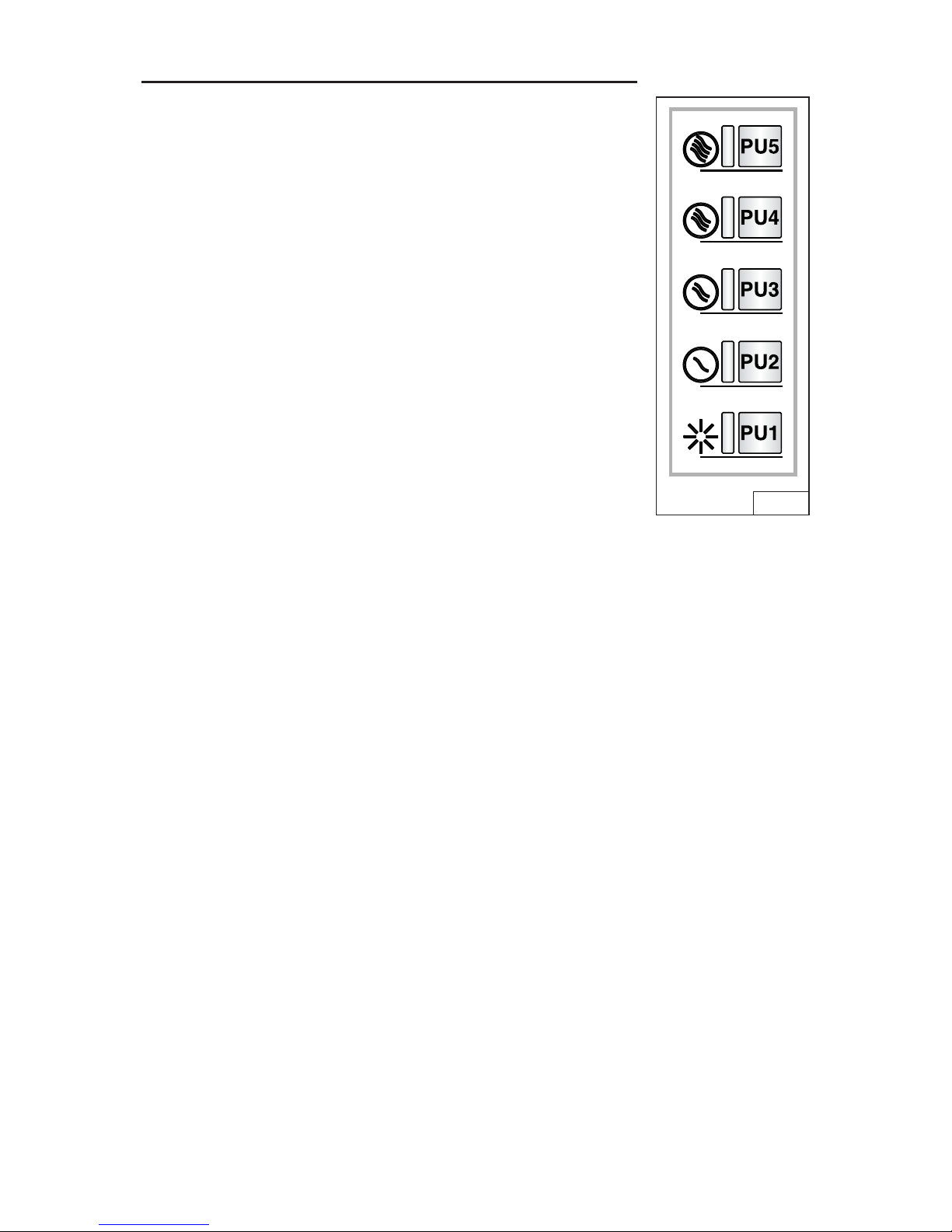
CONTROLS (FIG. 1)
Speed display:
PU5: ON/OFF Motor 4
th
speed
PU4: ON/OFF Motor 3
rd
speed
PU3: ON/OFF Motor 2
nd
speed
PU2: ON/OFF Motor 1
st
speed
PU1: HI/LOW/OFF Lights
10-minute timer function:
Pressing PU2, PU3 or PU4 for two seconds when the motor
is set to the corresponding speed, activates the 10-minute
timer function.
The corresponding LED starts blinking to display this function.
After ten minutes of operation the motor is turned off. If you
change the speed while the timer is running, the function
is NOT deactivated. To deactivate the function, press the
blinking key for two seconds.
FIG. 1
NOTE – the 10-minute timer function can be activated for the normal speeds
only (1st, 2nd, 3rd).
Filter alarm:
After 30 hours of motor operation, the grease filter alarm is activated (all the
LEDs come on). The alarm is activated when the motor is off and remains
displayed for 30 minutes. To deactivate the alarm, press one of the keys for 2
seconds during alarm display. After 120 hours of motor operation, the charcoal
filter alarm is activated (all the LEDs blink). The alarm is activated when the motor
is off and remains displayed for 30 minutes. To deactivate the alarm, press one of
the keys for 2 seconds during alarm display.
HEAT SENTRY™
Your hood is equipped with a HEAT SENTRY™ thermostat. This thermostat is a
device that will turn on or speed up the blower if it senses excessive heat above
the cooking surface.
1) If blower is OFF - it turns blower ON to HIGH speed.
2) If blower is ON at a lower speed setting - it turns blower up to HIGH speed.
When the temperature level drops to normal, the blower will return to its original
setting.
WARNING
The HEAT SENTRY thermostat can start the blower even if the hood is turned
OFF. When this occurs, it is impossible to turn the blower OFF with its switch.
If you must stop the blower, do it from the main electrical panel.
Page 5
- 5 -
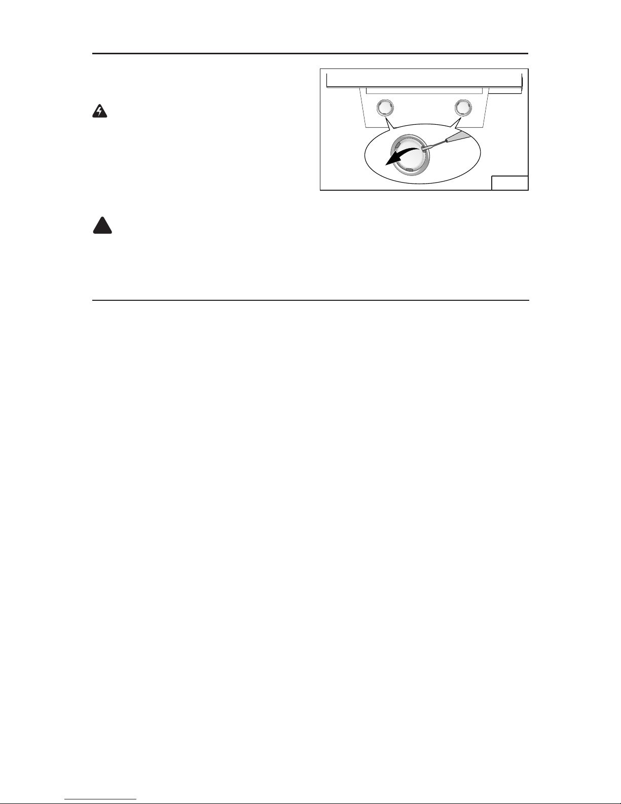
HALOGEN BULBS
This range hood requires two halogen
bulbs (Type T4, 120Volt, 25Watt Max,
G9 Base).
WARNING: Always switch off the
electrical supply before carrying out
any operation on the appliance.
To change bulbs:
1. Open the cover by prying from the
proper slots. Fig. 2.
2. Remove the bulbs by pulling sideways. (DO NOT ROTATE).
!
CAUTION: Bulbs may be hot.
3. Replace with Type T4, 120Volt, 25Watt Max, G9 Base halogen bulbs. Do not
touch replacement bulbs with bare hands!
FIG. 2
CLEANING AND MAINTENANCE
Proper maintenance of the Range Hood will assure proper performance of the unit.
Motor
The motor is permanently lubricated and never needs oiling. If the motor bearings make
excessive or unusual noise, replace the motor with the exact service motor. The impeller
should also be replaced.
Grease Filter
The grease filter should be cleaned frequently. Use a warm detergent solution. Grease filter
is dishwasher safe.
Clean all-metal filters in the dishwasher using a non-phosphate detergent. Discoloration of
the filter may occur if using phosphate detergents, or as a result of local water conditions
- but this will not affect filter performance. This discoloration is not covered by the warranty.
See “INSTALL FILTERS” section for removal and installation instructions.
Non-ducted Recirculation Filter
The non-ducted recirculation filter should be changed every 6 months. Replace more often if
your cooking style generates extra grease, such as frying and wok cooking. See “INSTALL
FILTERS” section for removal and installation instructions.
Stainless Steel Cleaning
DO:
• Regularly wash with clean cloth or rag
soaked with warm water and mild soap
or liquid dish detergent.
• Always clean in the direction of original
polish lines.
• Always rinse well with clear water (2 or 3
times) after cleaning. Wipe dry completely.
• You may also use a specialized household
stainless steel cleaner.
DON’T:
•
Use any steel or stainless steel wool or any
other scrapers to remove stubborn dirt.
• Use any harsh or abrasive cleansers.
• Allow dirt to accumulate.
• Let plaster dust or any other construction
residues reach the hood. During construction/renovation, cover the range hood to
make sure no dust sticks to the stainless
steel surface.
Avoid: When choosing a detergent
• Any cleaners that contain bleach will attack stainless steel
• Any products containing: chloride, fluoride, iodide, bromide will deteriorate surfaces rapidly.
• Any combustible products used for cleaning such as acetone, alcohol, ether, benzol, etc.,
are highly explosive and should never be used close to a range.
Page 6

- 6 -
PREPARE THE HOOD
Unpack hood and check contents.
You should receive:
1 - Hood
1 - Decorative Flue Assembly
1 - Parts Bag containing:
2 - Mounting Brackets
1 - Discharge Collar
1 - Flue Mounting Bracket
8 - Mounting Screws (4.8 x 38mm Pan Head)
2 - Mounting Screws (3.9 x 9.5mm Pan Head)
8 - Drywall Anchors
1 - Installation Instructions
2 MOUNTING
BRACKETS
DISCHARGE
COLLAR
FLUE MOUNTING
BRACKET
8 MOUNTING SCREWS
(4.8 x 38mm Pan Head)
8 DRYWALL
ANCHORS
2 MOUNTING
SCREWS (3.9 x
9.5mm Pan Head)
DECORATIVE
FLUE
FIG. 3
Page 7
- 7 -
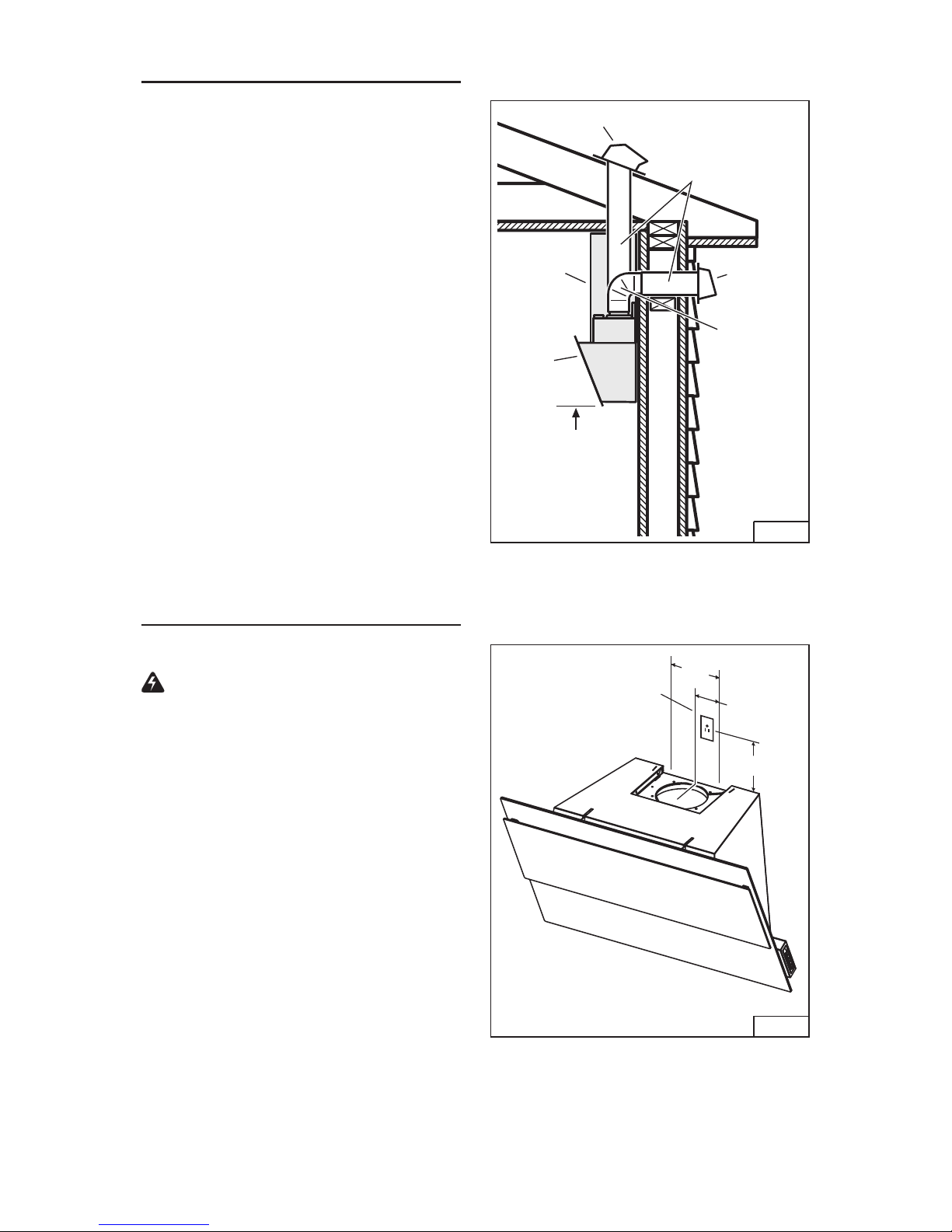
INSTALL THE DUCTWORK
DUCTED HOODS ONLY
CAUTION: To reduce the risk of fire,
use only metal ductwork.
1. Decide where the ductwork will run
between the hood and the outside.
Fig. 4.
2. A straight, short duct run will allow
the hood to perform most efficiently.
3. Long duct runs, elbows, and transitions will reduce the performance of
the hood. Use as few of them as possible. Larger ducting may be required
for best performance with longer duct
runs.
4. Install a roof or wall cap. Connect
round metal ductwork to cap and
work back towards hood location. Use
duct tape to seal the joints between
ductwork sections.
INSTALL ELECTRICAL
DUCTED and NON-DUCTED HOODS
WARNING : Electrical wiring must
be done by a qualified person(s) in
accordance with all applicable codes
and standards. This range hood must
be properly grounded. Turn off electrical power at service entrance before
wiring.
1. Plan where the hood will be located
above the cook top. Refer to the
“INSTALL MOUNTING BRACKET”
section for hood mounting height
options.
2. Install a standard 2” x 4” wall outlet
box and 3-blade 125 volt, 15 Amp
grounded receptacle.
3. Mount the center of the wall outlet 5”
to
8” above the bottom of the hood.
Fig. 5.
4. Locate the box and the receptacle
within boundary shown and off center
of the ductwork (to allow for power
cord plug and flue clearance).
FIG. 4
FIG. 5
6" ROUND
DUCT
ROOF CAP
6" ROUND
ELBOW
20" TO 30" ABOVE
COOKING SURFACE
(see “INSTALL
MOUNTING
BRACKETS”
section for mounting
restrictions)
WALL CAP
HOOD
DECORATIVE
FLUE
8
5
”
to
4¼”
8½”
CENTERLINE
OF HOOD
”
Page 8
- 8 -
HOOD DISTANCE ABOVE 36” HIGH COOK TOP (see note below)
26”
MOUNTING BRACKET LOCATION ABOVE 36” HIGH COOK TOP
CEILING
HEIGHT
8 FEET
20” 21” 22” 23” 24” 25”
34-1/2” 35-1/2” 36-1/2” 37-1/2”
DUCTED
NON-DUCTED
DUCT
METHOD
34-1/2” 35-1/2”
9 FEET
DUCTED
NON-DUCTED
35-1/2” 36-1/2” 37-1/2”
38-1/2” 39-1/2” 40-1/2”
41-1/2”
42-1/2” 43-1/2” 44-1/2”
30”27” 28” 29”
38-1/2” 39-1/2” 40-1/2”
41-1/2”
42-1/2” 43-1/2” 44-1/2”
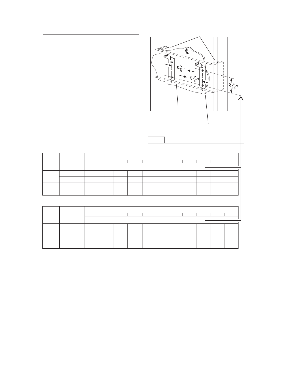
INSTALL MOUNTING
BRACKET
DUCTED and NON-DUCTED HOODS
1. Construct wood wall framing that
is flush with interior surface of wall
studs. Fig. 6.
Make sure:
a) the framing is centered over in-
stallation location.
b) the height of the framing will al-
low the mounting brackets to be
secured to the framing within the
dimensions shown.
2. After wall surface is finished, secure each mounting bracket to framing with (2) 4.8 x 38 mm mounting
screws. See chart below for mounting
bracket location.
FRAMING BEHIND
WOOD CROSS
SUPPORT
WOOD CROSS
SUPPORT BEHIND
DRYWALL
DRYWALL
FIG. 6
INSTALLATIONS WITH FLUE
HOOD DISTANCE ABOVE 36” HIGH COOK TOP (see note below)
26”
MOUNTING BRACKET LOCATION ABOVE 36” HIGH COOK TOP
CEILING
HEIGHT
20” 21” 22” 23” 24” 25”
34-1/2”
35-1/2”
36-1/2”
37-1/2”
NON-DUCTED
DUCT
METHOD
30”27” 28” 29”
38-1/2”
39-1/2”
40-1/2”
41-1/2”
42-1/2”
43-1/2”
44-1/2”
8 or
9 FEET
NON-DUCTED INSTALLATIONS WITHOUT FLUE (WITH BLADE GUARD ONLY)
Note: Minimum hood distance above cook top must not be less than 20". A maximum of 30" above cook top is highly recommended for best capture of cooking
impurities. Distance over 30" are the installer and user's discrection; and if ceiling
height and flue lenght permit.
Page 9
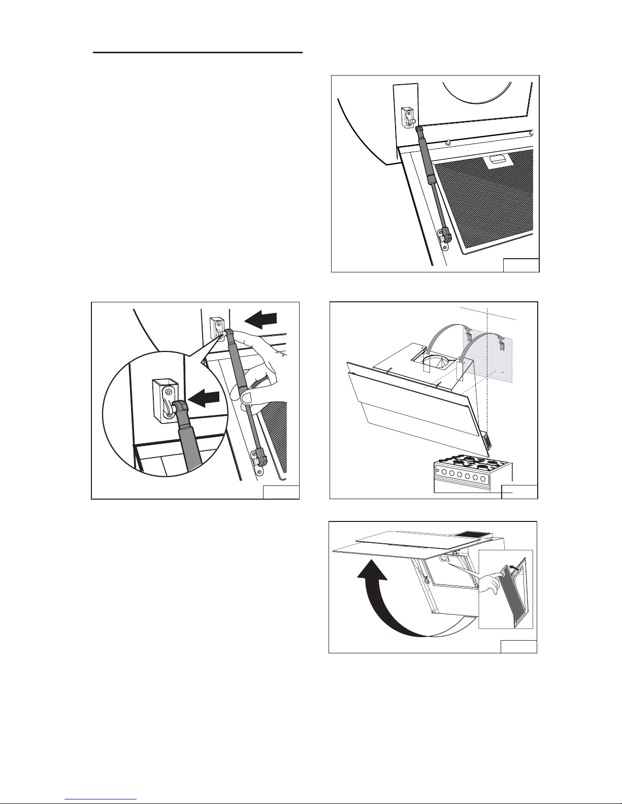
INSTALL THE HOOD
Note: Remove the plastic protective
film from all exterior surfaces,
decorative flues and filters, prior to
final insallation.
DUCTED and NON-DUCTED
INSTALLATION
1. Open the front glass panel and
remove shipping tape from both air
cylinders.
2. Pull each cylinder to extend its lenght.
Fig.7
3. Align end of cylinder with mounting
bracket and push in to engange. Fig.8
4. Install hood onto (2) wall mounting
brackets. Make sure hood is level with
floor. Fig.9
5. Lift glass front panel and remove
grease filter.Fig 10.
FIG.
Click!
8
0
FIG.1
FIG. 7
FIG. 9
- 9 -
Page 10
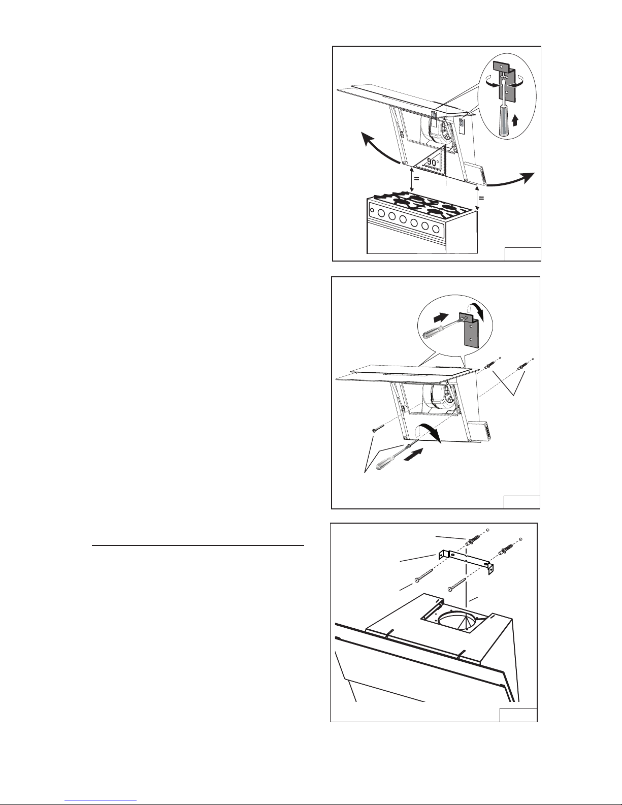
6. Use adjustment screws on wall
brackets to level hood. Fig.11
7. From inside the hood, locate (2) holes
for drywall anchors. Mark their location
on the wall.
8. Remove hood from the wall and drill
(2) 5/16” holes. Install drywall anchors as
shown. Fig.12
9. Lift hood back onto wall mounting
brackets. Secure hood to the wall with
(2) 4.8 x 38mm mounting screws.
DUCTED AND NON-DUCTED
INSTALLATION WITH FLUE CONTINUE TO “INSTALL FLUE
MOUNTING BRACKET” SECTION
ON PAGE 10
NON-DUCTED INSTALLATIONS
WITHOUT FLUE SKIP TO “INSTALL BLADE GUARD”
SECTION ON PAGE 14
INSTALL FLUE MOUNTING
BRACKET
DUCTED OR NON-DUCTED HOOD
WITH FLUE
1. Center the mounting bracket directly
over the range hood location.
2. Secure the bracket to the wall using
(2) 4.8 x 38mm mounting screws and
drywall anchors. Fig7. Make sure the
bracket is tight against the wall and
centered over the hood. Fig.13
FIG.13
4.8 x 38 mm
SCREWS
DRYWALL
ANCHORS
CENTERLINE
OF HOOD
4.8 x 38 mm
SCREWS
DRYWALL
ANCHORS
MOUNTING
BRACKET
FIG.11
FIG.12
- 10 -
Page 11
- 11 -
FIG.14
FIG.15
FIG.16
DUCTED INSTALLATION ONLY
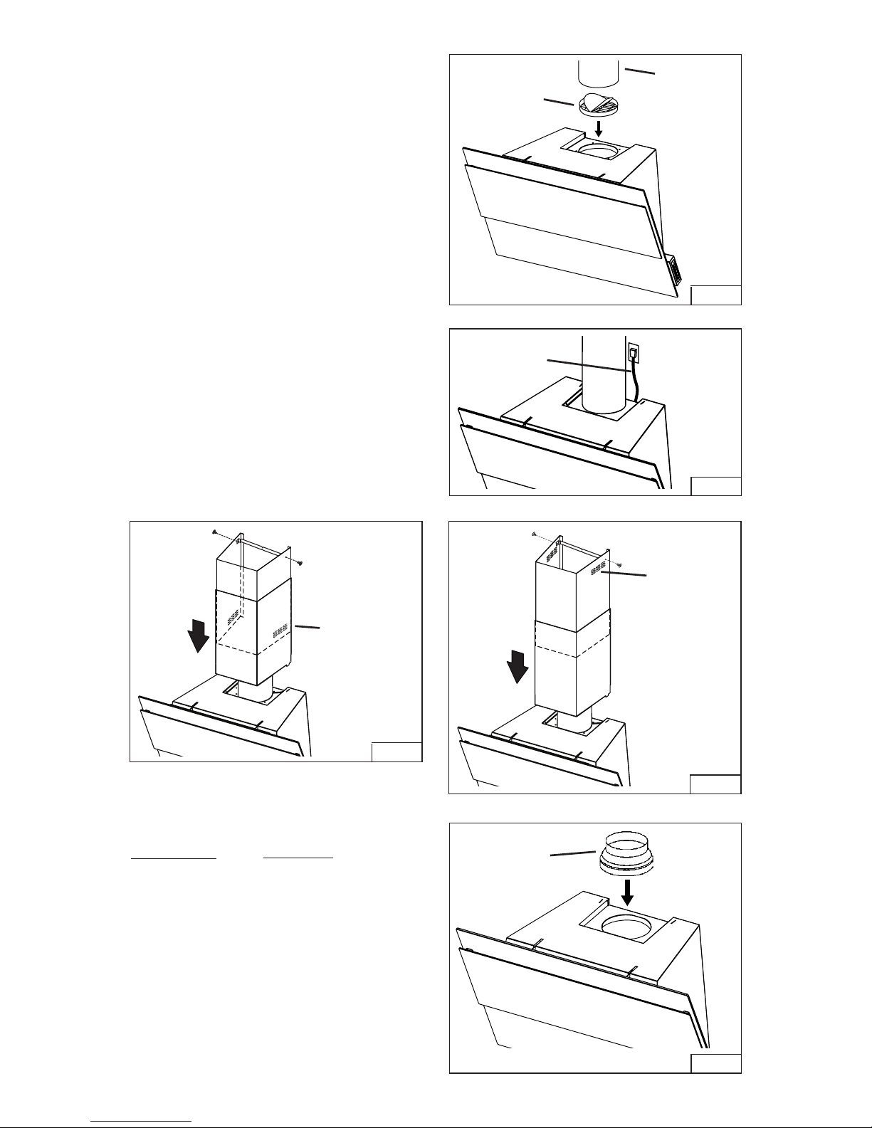
10. Press the discharge collar into the
duct connector of the range hood.
Fig. 14.
11. Run 6” diameter metal ductwork
to the outside location. Install an
appropriate wall or roof cap with
damper to exhaust air to the outside.
12. Tape all duct joints with aluminum
duct tape.
13. Plug power cord into wall outlet. Fig.
15.
14. Install upper and lower decorative
flues onto the range hood.
- Vents are concealed on 8-foot
ceilings. Fig. 16
- Vents are exposed on 9-foot ceilings. Fig. 17.
15. Secure upper flue to flue mounting
bracket with (2) 3.9 x 6 mm screws.
DISCHARGE
COLLAR
6” ROUND
DUCT
POWER
CORD
FIG.17
VENTS
CONCEALED
8 FT. CEILING
VENTS
EXPOSED
9 FT. CEILING
NON-DUCTED INSTALLATION
WITH FLUE AND PLENUM ONLY
Note: Purchase Model ANKWM34 Nonducted Recirculation Kit.
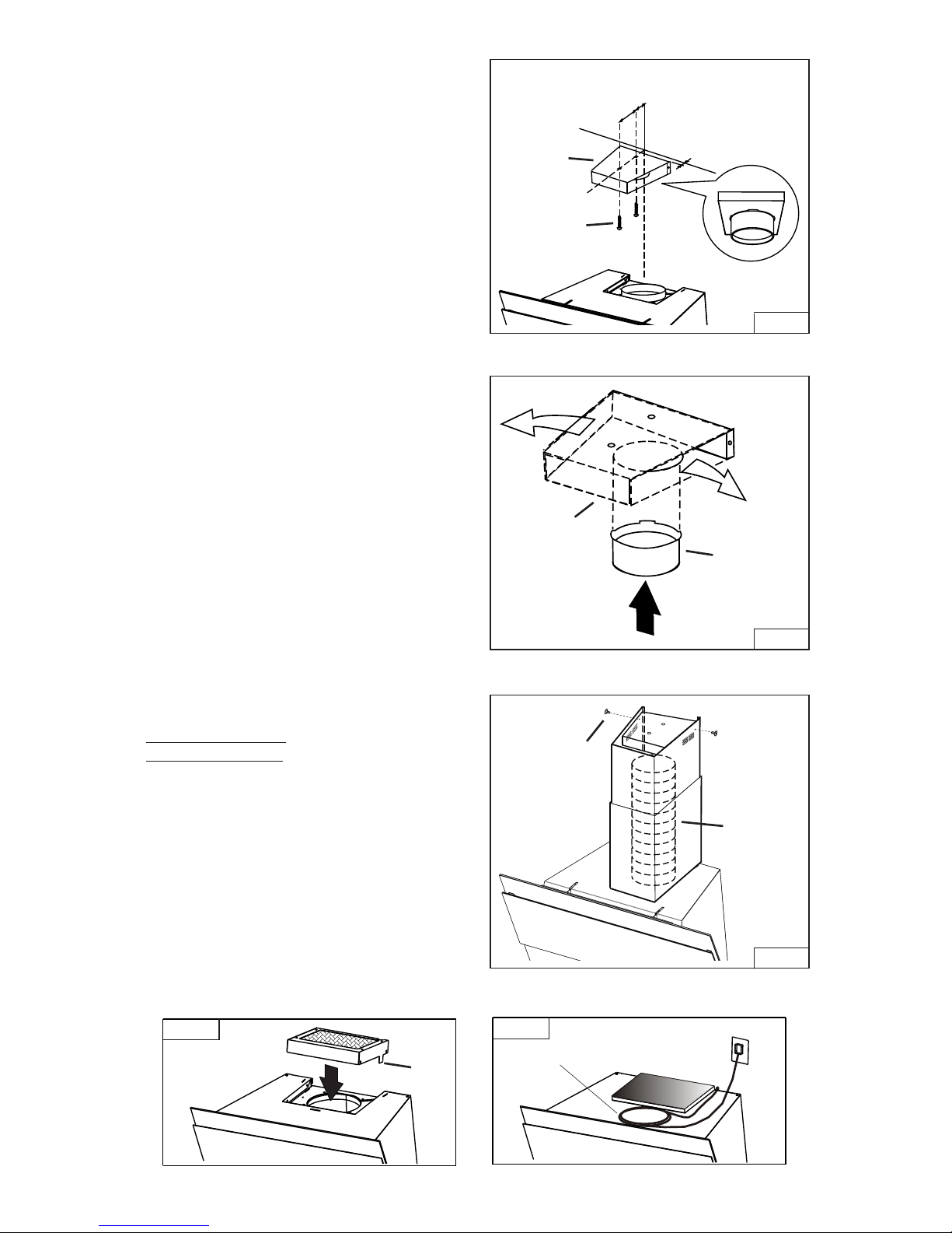
10. Do not install discharge collar
supplied with the range hood.
11. Attach the 5”-to-6” adapter to
blower discharge and tape joint with
aluminum duct tape. Fig. 18.
FIG.18
5” TO 6”
ADAPTER
Page 12
- 12 -
12. Center the plenum over the hood.
Fig. 19.
13. Attach plenum to the ceiling using
(2) drywall anchors and (2) 4.8 x 38
mm screws, as shown.
14. Press duct connector into the
plenum until it snaps into place. Fig.
20.
15. Attach 5-inch dia. expandable
ducting to the plenum and tape joint
with aluminum duct tape.
16. Stretch expandable duct, attach it to
the 5”-to-6” adapter and tape duct
joints. Fig. 21.
1 7. Plug power cord into wall outlet.
18. Position upper and lower flues onto
the hood.
19. Align tabs on bottom edge of lower
flue with slots on top of the range
hood.
20. Make sure recirculation slots on the
upper flue are exposed, as shown.
2 1. Lift upper flue up until mounting
holes align with holes in the plenum.
22. Install (2) 3.9 x 9.5 mm mounting
screws to secure upper flue to
plenum.
FIG.20
FIG.19
FIG.21
5-7/8”
1-3/8”
3/8”
4.8 x 38mm
SCREWS
PLENUM
PLENUM
DUCT
CONNECTOR
3.9 x 6mm
SCREWS
5” DIA.
EXPANDABLE
DUCT
NON-DUCTED INSTALLATION
WITHOUT FLUE AND
BLADE GUARD ONLY
10. Install blade guard. Align tabs of the
guard with slots on top of the hood.
Fig.22
11. From inside the hood , bend tabs
over to secure the blade guard to the
hood.
12. Plug power cord into 120 VAC
receptacle . Fig.23
13. Coil and tape remaining power cord
to the top of the range hood.
FIG.22
TABS
FIG.23
TAPE
Page 13
- 13 -
INSTALL FILTERS
DUCTED AND NON-DUCTED HOODS
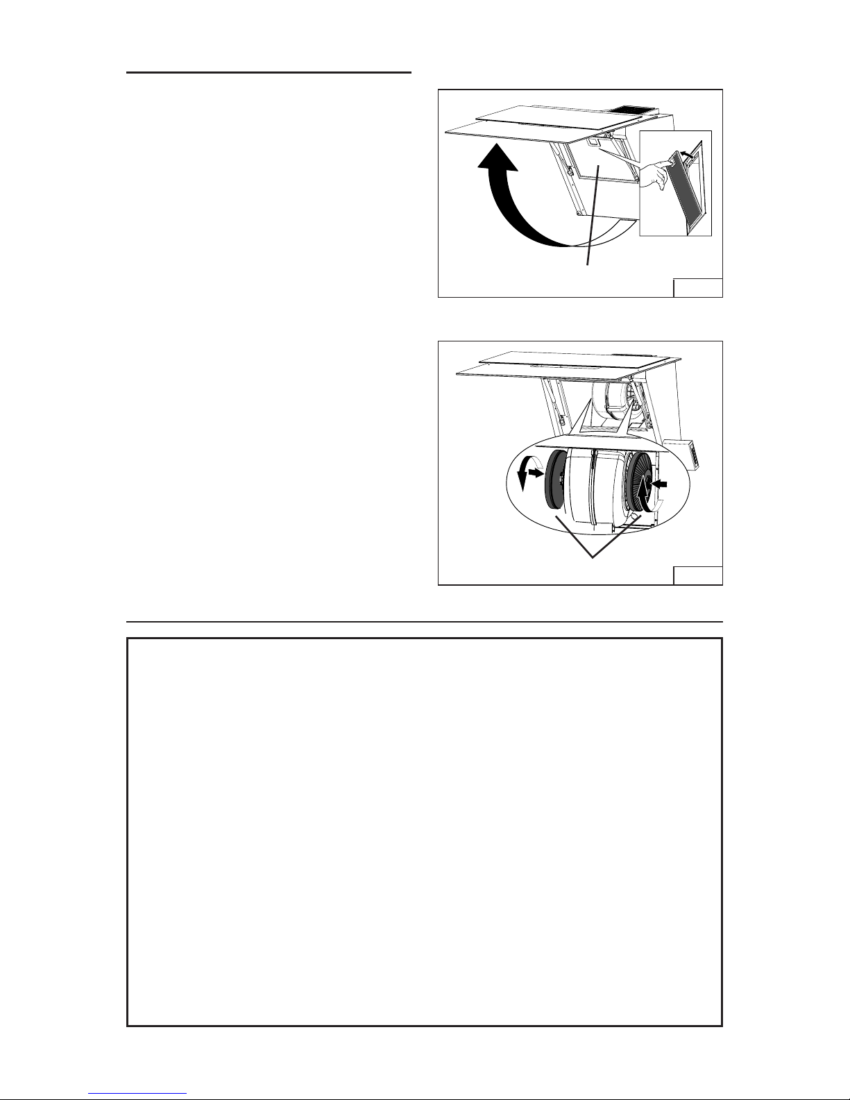
1. To remove the GREASE filter, push in
latch tab to disengage the filter from
the hood. Tilt the filter downward and
remove. Fig. 24.
2. To install the GREASE filter, align rear
filter tabs with slots in the hood. Push
latch tab in, push filter into position
and release. Make sure the filter is
securely engaged after installation.
NOTE: Prior to use, remove protective
film from the filter frame.
NON-DUCTED HOODS ONLY
1. Lift glass front panel and remove
the grease filter.
2. Install (2) charcoal filters to the
blower, as shown. Fig. 25
3. Re-install grease filter and close the
front panel.
WARRANTY
ONE YEAR LIMITED WARRANTY FOR BEST PRODUCTS
Broan-NuTone LLC (Broan-NuTone) warrants to the original consumer purchaser of Best products that such products
will be free from defects in materials or workmanship for a period of one year from the date of original purchase. THERE
ARE NO OTHER WARRANTIES, EXPRESS OR IMPLIED, INCLUDING, BUT NOT LIMITED TO, IMPLIED WARRANTIES OR MERCHANT ABILITY OR FITNESS FOR A PARTICULAR PURPOSE.
During this one-year period, Broan-NuTone will, at its option, repair or replace, without charge, any product or part which
is found to be defective under normal use and service.
THIS WARRANTY DOES NOT EXTEND TO FLUORESCENT LAMP STARTERS, TUBES, HALOGEN AND INCANDESCENT BULBS, FUSE, FILTERS, DUCTS, ROOF CAPS, WALL CAPS AND OTHER ACCESSORIES FOR DUCTING.
This warranty does not cover (a) normal maintenance and service or (b) any products or parts which have been subject
to misuse, negligence, accident, improper maintenance or repair (other than by Broan-NuTone), faulty installation or
installation contrary to recommended installation instructions.
The duration of any implied warranty is limited to the one-year period as specified for the express warranty. Some states
do not allow limitation on how long an implied warranty lasts, so the above limitation may not apply to you.
BROAN-NUTONE’S OBLIGATION TO REPAIR OR REPLACE, AT BROAN-NUTONE’S OPTION, SHALL BE THE
PURCHASER’S SOLE AND EXCLUSIVE REMEDY UNDER THIS WARRANTY. BROAN-NUTONE SHALL NOT BE LIABLE FOR INCIDENTAL, CONSEQUENTIAL OR SPECIAL DAMAGES ARISING OUT OF OR IN CONNECTION WITH
PRODUCT USE OR PERFORMANCE. Some states do not allow the exclusion or limitation of incidental or consequential
damages, so the above limitation or exclusion may not apply to you.
This warranty gives you specific legal rights, and you may also have other rights, which vary from state to state. This
warranty supersedes all prior warranties.
To qualify for warranty service, you must (a) notify Broan-NuTone at the address stated below or telephone number stated
below, (b) give the model number and part identification and (c) describe the nature of any defect in the product or part.
At the time of requesting warranty service, you must present evidence of the original purchase date.
In USA - Best®, 926 W. State Street, Hartford, WI 53027 (800-558-1711)
In Canada - Best®, 550 Lemire Blvd., Drummondville, QC J2C 7W9 (866-737-7770)
www.BestRangeHoods.com
FIG.25
CHARCOAL FILTERS
FIG.24
GREASE FILTER
Page 14
- 14 -
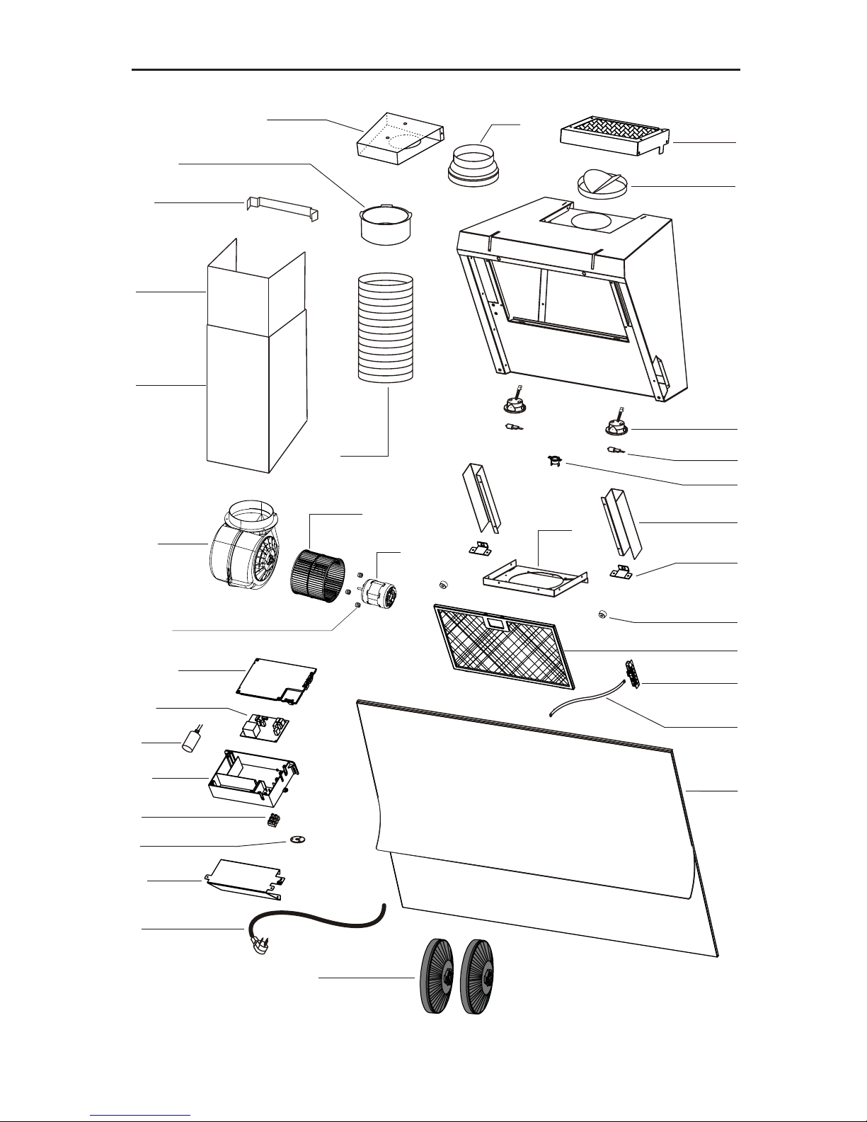
KEY NO.
5
9
14
16
26
37
38
45
48
49
53
58
60
67
76
86
118
119
120
122
147
166
167
195
332
415
472
474
503
AQI
-
-
-
-
PART NUMBER
B03115314
B08087827
B02300233
BE3350518
B02300890
B02300804
B03295595
BW0000021
B02310260
B03295071
B03204177
B03293180
B03295018
B02300249
B02300961
B08093024
B08088378
B03292300
BE3350842
BE3350841
BE3349246
B08093104
BR2300132
B08080852
B03295596
BE3351278
B03115207
B03202454
BE3350520
B02300918
B02011452
B06103891
B06002157
B06145125
B080810939
B03300495
DESCRIPTION
BLADE GUARD
GREASE FILTER
CAPACITOR
ELECTRICAL BOX SUPPORT
LAMP BULB
THERMOSTAT
ELECTRICAL PRINTED CIRCUIT BOARD BOX
BLOWER
MOTOR (CLOCKWISE)
FAN (CLOCKWISE)
RUBBER WASHER
RUBBER WASHER
OUTLET REDUCTION
FEEDER CABLE
WIRES
TOP GLASS
OUTLET FLANGE
OUTLET FLANGE
BOTTOM DUCTEXT.
UPPER DUCT EXT.
TELESCOPIC DUCT UPPER BRACKET
PLENUM
JUNCTION CLAMP
ELECTRICAL PRINTED CIRCUIT BOARD
ELECTRICAL BOX COVER
BRACKET
COVER
FAIRLEAD
BRACKET
HALOGEN LAMP
EXPANDABLE DUCT
SWITCH BOX ASSEMBLY
BLOWER ASSEMBLY (INCLUDES KEY NO. 46,
48, 49, 53)
ELECTRICAL INSTALLATION ASSEMBLY
(INCLUDES KEY NO.14,38,60,67,147,166,167)
FITTING SET
NON-DUCT FILTERS (2)
SERVICE PARTS
Page 15
474
26
332
472
195
(03293180) 53
9
167
14
166
38
415
147
16
503
AQI
67
76
120
119
118
60
37
45
49
48
53 (03204177)
122
86 (03292300)
(08088378) 86
58
5
NON-DUCT
FILTERS
SERVICE PARTS
- 15 -
Page 16

- 16 -
C
99044731C
04308265/1
Page 17

- 17 -
Modèle WM34I
ENGLISH.................................... 2
FRANÇAIS.................................17
ESPAÑOL.................................. 33
Aux États-Unis – BEST Hartford, Wisconsin
Au CANADA – BEST Drummondville, QC, Canada
ENREGISTREZ VOTRE PRODUIT EN LIGNE À L’ADRESSE : www.BestRangeHoods.com/register
Pour en savoir plus, visitez le site www.BestRangeHoods.com
Page 18

- 18 -
VEUILLEZ LIRE ET CONSERVER CES INSTRUCTIONS
AVERTISSEMENT
POUR RÉDUIRE LES RISQUES D’INCENDIE, D’ÉLECTROCUTION OU DE
BLESSURES PHYSIQUES, RESPECTEZ LES INSTRUCTIONS CI-DESSOUS :
1. Utilisez cet appareil uniquement de la manière prévue par le fabricant. Si vous avez des
questions, contactez le fabricant à l’adresse ou au numéro de téléphone indiqués dans la
garantie.
2. Avant d’effectuer l’entretien ou le nettoyage de l’appareil, mettez-le hors tension sur le
panneau de service et verrouillez ce dernier pour éviter que l’appareil soit mis sous tension
par inadvertance. S’il n’est pas possible de verrouiller le dispositif de déconnexion, apposez
un avertissement bien visible (par exemple une étiquette) sur le panneau de service.
3. L’installation et le raccordement électrique doivent être effectués par du personnel qualifié
conformément à toutes les réglementations et normes en vigueur, y compris celles concernant
les constructions cotées pour leur résistance au feu.
4. Afin d’éviter un refoulement lors de l’utilisation d’équipements à combustible, une quantité d’air
suffisante est nécessaire pour assurer une combustion et un échappement adéquats des gaz
à travers le conduit (la cheminée). Suivez les consignes du fabricant de l’équipement chauffant
et les normes de sécurité publiées, entre autres, par l’Association nationale de protection
contre l’incendie (NFPA) et l’American Society for Heating, Refrigeration and Air Conditioning
Engineers (ASHRAE), ainsi que les réglementations locales.
5. Quand vous effectuez une découpe ou un forage dans un mur ou un plafond, veillez à ne pas
endommager des câblages électriques ou d’autres équipements non visibles.
6. Les soufflantes canalisées doivent toujours être dirigées vers l’extérieur.
7. N’utilisez pas cet appareil avec un dispositif de commande de vitesse transistorisée séparé.
8. Pour réduire les risques d’incendie, utilisez uniquement des canalisations en métal.
INSTRUCTIONS DE MISE À LA TERRE
Cet appareil doit être mis à la terre. En cas de court-circuit électrique, la mise à la
terre réduit le risque d’électrocution grâce à un fil permettant au courant électrique de
s’échapper. Cet appareil est doté d’un cordon ayant un fil de terre, ainsi que d’une fiche de
mise à la terre. La fiche doit être branchée dans une prise bien installée et mise à la terre.
AVERTISSEMENT – Une mise à la terre inappropriée peut donner lieu à un risque
d’électrocution.
Consultez un électricien qualifié si vous ne comprenez pas parfaitement les instructions
de mise à la terre ou si vous n’êtes pas certain(e) que l’appareil est mis à la terre comme
il se doit.
N’utilisez pas de rallonge. Si le cordon est trop court, demandez à un électricien d’installer
une prise près de l’appareil.
!
CONÇUE POUR LES CUISINES PRIVÉES UNIQUEMENT
!
Page 19

- 19 -
!
ATTENTION
1. Uniquement pour l’utilisation intérieure.
2. Pour réduire le risque d’incendie et obtenir un échappement d’air adéquat, veillez à bien
canaliser l’air vers l’extérieur. Ne ventilez pas l’air d’échappement vers des espaces confinés,
des plafonds, des combles, des vides sanitaires ou des garages.
3. Soyez prudent(e) quand vous utilisez des agents de nettoyage ou des détergents.
4. Évitez d’utiliser sous la hotte de cuisine des denrées alimentaires produisant des flammes.
5. À utiliser uniquement pour la ventilation générale. N’utilisez pas la hotte pour l’échappement
de matériaux ou de vapeurs comportant un danger ou un risque d’explosion.
6. Pour éviter que le roulement moteur s’endommage et que des hélices deviennent bruyantes
ou déséquilibrées, faites en sorte que le bloc d’alimentation n’entre pas en contact avec un
atomiseur pour cloisons sèches, de la poussière de construction, etc.
7. Le moteur de la hotte est doté d’un rupteur thermique qui éteint automatiquement le moteur
en cas de surchauffe. Le moteur redémarrera après avoir refroidi. Si le moteur s’éteint et se
rallume constamment, faites réparer la hotte.
8. Pour mieux capturer les impuretés de cuisson, la partie inférieure de la hotte doit se trouver
au minimum à 60 cm (20 po) et au maximum à 75 cm (30 po) au-dessus de la surface de
cuisson. Consultez la section « Installation du support de montage » pour connaître les
restrictions de montage.
9. Étant donné la taille et le poids de la hotte, il est conseillé d’avoir recours à deux personnes
pour la monter.
10. Ce produit est doté d’un thermostat qui peut activer la soufflante automatiquement. Pour éviter
les risques de blessure et l’allumage accidentel de la hotte, mettez-la hors tension sur le
panneau de service et verrouillez ce dernier ou fixez-y une étiquette d’avertissement.
11. Pour en savoir plus et connaître les exigences sur le produit, veuillez lire l’étiquette des
spécifications.
AVERTISSEMENT
POUR RÉDUIRE LE RISQUE D’UN FEU DE FRITURE SUR LA TABLE DE CUISSON :
A. Ne laissez jamais les appareils de surface sans surveillance quand ils sont sur un réglage
élevé. Les débordements peuvent provoquer de la fumée et des déversements gras risquant
de prendre feu. Chauffez les huiles lentement sur un réglage bas ou moyen.
B. ALLUMEZ toujours la hotte quand vous cuisinez à une chaleur élevée ou quand vous flambez
des aliments (p. ex. des crêpes Suzette, des cerises jubilé ou du bœuf au poivre flambé).
C. Nettoyez souvent les ventilateurs d’aération. Évitez que de la graisse s’accumule sur le
ventilateur ou le filtre.
D. Utilisez des poêles de la taille appropriée. Utilisez toujours des ustensiles de cuisine adaptés
à la taille de l’élément de surface.
POUR RÉDUIRE LE RISQUE DE BLESSURES PHYSIQUES EN CAS DE FEU DE
FRITURE SUR LA TABLE DE CUISSON, VEUILLEZ PROCÉDER COMME SUIT : *
1. ÉTOUFFEZ LES FLAMMES avec un couvercle hermétique, une plaque à biscuits ou un
plateauen métal, puis éteignez le brûleur. SOYEZ PRUDENT(E) AFIN D’ÉVITER LES
BRÛLURES. Siles flammes ne s’éteignent pas immédiatement, ÉVACUEZ LE LIEU ET
APPELEZ LE SERVICE DES POMPIERS.
2. NE SAISISSEZ JAMAIS UNE POÊLE ENFLAMMÉE, vous risquez de vous brûler.
3. N’UTILISEZ JAMAIS D’EAU ni de torchons ou serviettes mouillé(e)s : cela donnerait lieu à une
violente explosion de vapeur.
4. Utilisez un extincteur UNIQUEMENT si :
A. Vous savez qu’il s’agit d’un extincteur de Classe ABC et savez déjà comment vous en
servir.
B. L’incendie est de petite taille et confiné à l’endroit où il a commencé.
C. Le service des pompiers a été averti.
D. Vous pouvez éteindre l’incendie en ayant une sortie derrière vous.
* Basé sur « Kitchen Fire Safety Tips », publié par la NFPA.
Page 20

- 20 -
FONCTIONNEMENT
COMMANDES (FIG. 1)
Affichage de vitesse :
PU5 : MARCHE/ARRÊT Moteur 4
e
vitesse
PU4 : MARCHE/ARRÊT Moteur 3
e
vitesse
PU3 : MARCHE/ARRÊT Moteur 2
e
vitesse
PU2 : MARCHE/ARRÊT Moteur 1
e
vitesse
PU1 : Ampoules HAUTE/BASSE/ARRÊT
Fonction de la minuterie 10 minutes :
Enfoncer PU2, PU3 ou PU4 pendant deux secondes lorsque le moteur est réglé à la vitesse correspondante, active
la fonction de minuterie de 10 minutes.
La DEL correspondante commence à clignoter pour afficher
cette fonction.
Après dix minutes de marche, le moteur s’éteint. Si vous
changez la vitesse pendant que la minuterie fonctionne, la
fonction N’est PAS désactivée. Pour désactiver cette fonction,
appuyez sur la touche clignotante pendant deux secondes.
FIG. 1
REMARQUE – la fonction de la minuterie 10 minutes peut être activée pour
les vitesses normales seulement (1e, 2e, 3e).
Alarme du filtre :
Après 30 heures de fonctionnement du moteur, l’alarme du filtre à graisse s’active
(toutes les DEL s’allument). L’alarme est activée lorsque le moteur est éteint et
reste affichée pendant 30 secondes. Pour désactiver l’alarme, appuyez sur l’une
des touches pendant 2 secondes durant l’affichage de l’alarme. Après 120 heures
de fonctionnement du moteur, l’alarme du filtre à charbon est activée (toutes les
DEL clignotent). L’alarme est activée lorsque le moteur est éteint et reste affichée
pendant 30 secondes. Pour désactiver l’alarme, appuyez sur l’une des touches
pendant 2 secondes durant l’affichage de l’alarme.
HEAT SENTRY™
La hotte est équipée d’un thermostat HEAT SENTRY™. Ce dispositif active ou accélère
la soufflante s’il détecte une chaleur excessive au-dessus de la surface de cuisson.
1) Si la soufflante est ARRÈTÉE, il l’ALLUME en HAUTE vitesse.
2) Si la soufflante est ALLUMÉE à une vitesse basse, il la fait passer à la vitesse HAUTE.
Quand la température redevient normale, la soufflante revient au réglage d’origine.
AVERTISSEMENT
Le thermostat HEAT SENTRY peut activer la soufflante même si la hotte est
ÉTEINTE. Dans ce cas, il est impossible de DÉSACTIVER la soufflante avec
le commutateur d’arrêt. Si vous devez arrêter la soufflante, faites-le depuis le
panneau électrique principal.
Page 21

- 21 -
AMPOULES HALOGÈNES
Cette hotte de cuisine nécessite deux ampoules
halogènes (Type T4, 120 V, 25 W max., base G9).
AVERTISSEMENT : Désactivez toujours
l’alimentation avant d’effectuer toute
opération sur l’appareil.
Pour changer les ampoules :
1. Ouvrez le couvercle en faisant levier sur les
fentes prévues à cet effet. Fig. 2.
2. Retirez les ampoules en les tirant vers le côté.
(NE LES TOURNEZ PAS).
!
ATTENTION : Il est possible que les ampoules soient chaudes.
3. Remplacez-les par des ampoules halogènes de type T4, 120 V, 25 W max., base G9.
Netouchez pas les ampoules de rechange à mains nues!
FIG. 2
NETTOYAGE ET ENTRETIEN
Pour assurer les performances de l’appareil, entretenez-le de manière appropriée.
Moteur
Le moteur est lubrifié en permanence et aucun graissage n’est nécessaire. Si les roulements du
moteur font un bruit excessif ou inhabituel, remplacez le moteur par une pièce de rechange identique.
Remplacez aussi les hélices.
Filtre à graisse
Le filtre à graisse doit être nettoyé souvent. Vous pouvez utiliser une solution détergente chaude. Le
filtre peut être mis dans le lave-vaisselle.
Nettoyez tous les filtres en métal dans le lave-vaisselle avec un détergent sans phosphate. Si vous
utilisez un détergent phosphaté ou selon le type d’eau, il est possible que le filtre se décolore, mais
cela n’affectera aucunement ses performances. Cette décoloration n’est pas couverte par la garantie.
Consultez la section « INSTALLATION DES FILTRES » pour connaître les instructions de retrait et
d’installation.
Filtre de recirculation non canalisé
Le filtre de recirculation non canalisé doit être changé tous les 6 mois. Si votre style de cuisine engendre
beaucoup de graisse, par exemple si vous faites souvent de la friture ou si vous utilisez un wok,
remplacez-le plus souvent. Consultez la section « INSTALLATION DES FILTRES » pour connaître les
instructions de retrait et d’installation.
Nettoyage de l’acier inoxydable
À FAIRE :
• Nettoyez régulièrement l’acier inoxydable avec
un chiffon ou un torchon enduit d’eau chaude
et de savon doux ou de liquide vaisselle.
• Nettoyez toujours dans le sens des lignes de
polissage d’origine.
• Rincez toujours à l’eau claire (2 ou 3 fois) après
le nettoyage. Essuyez complètement.
• Vous pouvez aussi utiliser un nettoyant spécial
pour acier inoxydable d’électroménagers.
À NE PAS FAIRE :
• N’utilisez pas de laine d’acier inoxydable ni
d’autres racloirs pour éliminer la saleté difficile
à éliminer.
• N’utilisez pas de produits de nettoyage durs
ou abrasifs.
• Ne laissez pas la poussière s’accumuler.
• Ne laissez pas la poussière de plâtre ou
d’autres résidus de construction se poser sur la
hotte. Pendant la construction/les rénovations,
couvrez la hotte afin d’éviter qu’aucune poussière
n’adhère aux surfaces en acier inoxydable.
À éviter quand vous choisissez un détergent :
• Tous les produits de nettoyage contenant de l’eau de Javel attaquent l’acier inoxydable.
• Tous les produits contenant du chlore, du fluor, de l’iode ou du bromure provoquent une détérioration
rapide des surfaces.
• Tous les produits combustibles utilisés pour le nettoyage, tels que l’acétone, l’alcool, l’éther, le benzène
sont extrêmement explosifs et ne doivent jamais être employés à proximité d’une table de cuisson.
Page 22

- 22 -
PRÉPARATION DE LA HOTTE
Déballez la hotte et vérifiez le contenu de l’emballage.
Il doit comprendre :
1 – Hotte
1 – Ensemble de carneau décoratif
1 – Sac de pièces contenant :
2 – Supports de montage
1 – Collet de refoulement
1 – Support de montage du carneau
8 – Vis de montage (à tête cylindrique de 4,8 x 38 mm)
2 – Vis de montage (à tête cylindrique de 3,9 x 9,5 mm)
8 – Ancrages pour cloison sèche
1 – Instructions d’installation
2 SUPPORTS
DE MONTAGE
COLLET DE
REFOULEMENT
SUPPORT
DE MONTAGE DU CARNEAU
8 VIS DE MONTAGE (à tête
cylindrique de 4,8 x 38 mm)
8 ANCRAGES
POUR CLOISON
SÈCHE
2 VIS DE MONTAGE
(à tête cylindrique de
3,9 x 9,5 mm)
CARNEAU
DÉCORATIF
FIG. 3
Page 23

- 23 -
INSTALLATION DE LA
CANALISATION
HOTTES CANALISÉES UNIQUEMENT
ATTENTION : Pour réduire les risques
d’incendie, utilisez uniquement des
canalisations en métal.
1. Décidez à quel endroit passera la
canalisation entre la hotte et l’extérieur.
Fig. 4.
2. Une canalisation droite et courte assurera
une performance optimale de la hotte.
3. Une canalisation longue, coudée et les
transitions réduiront la performance de
la hotte. Utilisez-les le moins possible.
Si la canalisation est plus grosse, il
peut s’avérer nécessaire d’utiliser une
canalisation plus longue.
4. Installez une protection de toit ou de paroi.
Raccordez la canalisation métallique
ronde à la protection et reculez vers
l’emplacement de la hotte. Utilisez du
ruban adhésif en toile pour étanchéiser
les joints entre les sections de la
canalisation.
INSTALLATION ÉLECTRIQUE
HOTTES CANALISÉES et NON CANA-
LISÉES
AVERTISSEMENT :
Le câblage électrique
doit être réalisé par une personne qualifiée,
conformément aux réglementations et
normes en vigueur. Cette hotte de cuisine
doit être mise à la terre de manière adéquate.
Avant d’effectuer le câblage, coupez le
courant à l’origine de l’installation électrique.
1. Prévoyez où la hotte sera placée audessus de la table de cuisson. Consultez
la section « INSTALLATION DU
SUPPORT DE MONTAGE » pour savoir
à quelle hauteur la hotte peut être montée.
2. Installez une boîte à prises murale de
5 x 10 cm (2 po x 4 po) et un prolongateur
à 3 broches de 125 V, 15 A mis à la terre.
3. Montez le centre de la prise murale entre
12,7cm et 20,3 cm
(
5
et
8
po)
au-dessus
du bas de la hotte. Fig. 5.
4. Placez la boîte et le prolongateur dans les
limites indiquées et de manière décentrée
par rapport à la canalisation (afin de
laisser l’espace pour la protection du
cordon et le carneau).
FIG. 4
FIG. 5
CANALISATION RONDE
DE 15,2 cm (6 po)
PROTECTION DE TOIT
COUDE ROND
DE 15,2 cm
(6 po)
PROTECTION
DE PAROI
HOTTE
CARNEAU
DÉCORATIF
50,8 à 76,2 cm (20 à 30 po)
AU-DESSUS DE LA
SURFACE DE CUISSON
(voir la section
« INSTALLATION DES
SUPPORTS DE MONTAGE »
pour connaître les restrictions
de montage)
10,8 cm
(4 ¼ po)
21,6 cm
(8 ½ po)
LIGNE CENTRALE
DE LA HOTTE
12,7cm (5po) à
20,3cm (8po)
Page 24

- 24 -
ÉVENTS DE
PLAFOND
CONNECTEUR
MÉTHODE
DISTANCE DE LA HOTTE À 90 CM (36 po) AU-DESSUS DE LA TABLE DE CUISSON (voir remarque ci-dessous)
50,8 cm
(20 po)
53,3 cm
(21 po)
55,9 cm
(22 po)
58,4 cm
(23 po)
61 cm
(24 po)
63,5 cm
(25 po)
66 cm
(26 po)
68,6 cm
(27 po)
71,1 cm
(28 po)
73,7 cm
(29 po)
76,2 cm
(30 po)
EMPLACEMENT DU SUPPORT DE MONTAGE À 90 CM (36 po) AU-DESSUS DE LA TABLE DE CUISSON
2,4 M
(8PI)
CANALISÉE
87,6 cm
(34 1/2 po)
90,2 cm
(35 1/2 po)
92,7 cm
(36 1/2 po)
95,3 cm
(37 1/2 po)
NON
CANALISÉE
87,6 cm
(34 1/2 po)
90,2 cm
(35 1/2 po)
2,75 M
(9PI)
CANALISÉE
97,8 cm
(38 1/2 po)
100,3 cm
(39 1/2 po)
102,9 cm
(40 1/2 po)
105 cm
(411/2 po)
108 cm
(421/2 po)
110 cm
(431/2 po)
113 cm
(441/2po)
NON
CANALISÉE
90,2 cm
(35 1/2 po)
92,7 cm
(36 1/2 po)
95,3 cm
(37 1/2 po)
97,8 cm
(38 1/2 po)
100,3 cm
(39 1/2 po)
102,9 cm
(40 1/2 po)
105 cm
(411/2 po)
108 cm
(421/2 po)
110 cm
(431/2 po)
113 cm
(441/2po)
14,9 cm
(
4 1/
po)
14,9 cm
(
4 1/
po)
5,5 cm
(
4 1/
po)
INSTALLATION DU
SUPPORT DE MONTAGE
HOTTES CANALISÉES et NON
CANALISÉES
1. Construisez une structure murale en
bois à niveau avec la surface intérieure
des poteaux de cloison. Fig. 6.
Assurez-vous :
a) que la structure est centrée sur
l’emplacement de l’installation.
b) que la structure soit placée à une
hauteur permettant d’y fixer les
supports de montage conformément
aux dimensions indiquées.
2. Une fois que la surface murale est
terminée, fixez chaque support de
montage à la structure avec (2) vis de
montage de 4,8 x 38 mm. Consultez
le tableau ci-dessous pour connaître
l’emplacement du support de montage.
STRUCTURE DERRIÈRE
LE SUPPORT EN BOIS
CROISÉ
SUPPORT EN
BOIS CROISÉ
DERRIÈRE LA
CLOISON SÈCHE
CLOISON
SÈCHE
FIG. 6
ÉVENTS DE
PLAFOND
CONNECTEUR
MÉTHODE
DISTANCE DE LA HOTTE À 90 CM (36 po) AU-DESSUS DE LA TABLE DE CUISSON (voir remarque ci-dessous)
50,8 cm
(20 po)
53,3 cm
(21 po)
55,9 cm
(22 po)
58,4 cm
(23 po)
61 cm
(24 po)
63,5 cm
(25 po)
66 cm
(26 po)
68,6 cm
(27 po)
71,1 cm
(28 po)
73,7 cm
(29 po)
76,2 cm
(30 po)
EMPLACEMENT DU SUPPORT DE MONTAGE À 90 CM (36 po) AU-DESSUS DE LA TABLE DE CUISSON
87,6 cm
(34 1/2 po)
NON
CANALISÉE
90,2 cm
(35 1/2 po)
92,7 cm
(36 1/2 po)
95,3 cm
(37 1/2 po)
97,8 cm
(38 1/2 po)
100,3 cm
(39 1/2 po)
102,9 cm
(40 1/2 po)
105 cm
(411/2 po)
108 cm
(421/2 po)
110 cm
(431/2 po)
113 cm
(441/2po)
Remarque : La distance minimum de la hotte au-dessus de la table de cuisson ne doit pas
être inférieure à 50,8 cm (20 po). Il est fortement recommandé de placer la hotte à 76 cm
(30 po) au maximum au-dessus de la table de cuisson pour qu’elle capture au mieux les
impuretés culinaires. L’installateur et l’utilisateur peuvent s’ils le souhaitent – et si la hauteur
de plafond et la longueur du carneau le permettent – placer la hotte à plus de 75 cm (30 po)
de la table de cuisson.
2,42,75 M
(8 - 9 PI)
INSTALLATION NON CANALISÉES SANS CONDUIT
(SEULEMENT AVEC LA GRILLE)
INSTALLATION AVEC CONDUIT
OU
Page 25

- 25 -
FIG. 8
INSTALLATION DE LA
HOTTE
Remarque : Avant l’installation finale,
retirez la pellicule en plastique de toutes
les surfaces extérieures, des carneaux
décoratifs et des filtres.
INSTALLATION D’UNE HOTTE
CANALISÉE OU NON CANALISÉE
1. Ouvrez le panneau de verre avant
etretirez le ruban d’expédition des
deuxcylindres pneumatiques.
2. Tirez chaque cylindre pour l’allonger.
Fig.7.
3. Alignez l’extrémité du cylindre avec le
support de montage et enfoncez pour
engager. Fig. 8.
4. Installez la hotte dans (2) supports de
montage mural. Vérifiez que la hotte est
parallèle au sol. Fig. 9.
FIG. 7
Cliquez!
FIG. 9
FIG. 10
5. Soulevez le panneau avant en verre et
retirez le filtre à graisse. Fig. 10.
Page 26

- 26 -
6. Mettez la hotte à niveau en utilisant les (2)
vis fournies sur les supports de montage.
Fig. 12.
7. Prenez les repères et installez (2) autres
ancrages pour cloison comme illustré.
Fig. 13.
8. Fixez la hotte de cuisine au mur avec (2)
vis de montage de 4,8 x 38 mm.
9. Resserrez les vis supérieures des
supports de montage jusqu’à ce que la
hotte soit bien serrée contre le mur.
INSTALLATION CANALISÉE –
PASSEZ À L’ÉTAPE 10 DANS LE HAUT DE
LA PAGE 27.
INSTALLATION NON-CANALISÉE –
PASSEZ À L’ÉTAPE 10 DANS LE BAS DE
LA PAGE 27.
FIG. 12
FIG. 13
VIS
4,8 x 38mm
ANCRAGES
POUR
CLOISON
SÈCHE
FIG. 7
LIGNE
CENTRALE
DE LA
HOTTE
VIS
3,9 x 6 mm
ANCRAGES POUR
CLOISON SÈCHE
SUPPORT DE
MONTAGE
INSTALLATION DU SUPPORT
DE MONTAGE DU CARNEAU
HOTTES CANALISÉES ET
NON-CANALISÉE AVEC CARNEAU
1. Centrez le support de montage directement au-dessus de l’emplacement de
la hotte de cuisine.
2. Fixez le support au mur en utilisant
(2) vis de montage de 4,8 x 38 mm
et des ancrages pour cloison sèche.
Fig. 7. Assurez-vous que le support
de montage est bien serré contre le
mur et centré sur la hotte. Fig.13
Page 27

- 27 -
FIG. 14
FIG. 15
FIG. 16
INSTALLATIONS CANALISÉES
UNIQUEMENT
10. Appuyez sur le collet de refoulement
dans le connecteur de la canalisation
de la hotte. Fig. 14.
11. Faites passer la canalisation en métal
de 15 cm (6 po) de diamètre vers
l’emplacement extérieur. Installez une
protection de paroi ou de toit appropriée
avec le collet de refoulement afin que
l’air s’échappe vers l’extérieur.
12. Collez tous les joints de la canalisation
avec de l’adhésif pour canalisation en
aluminium.
13. Branchez le cordon dans la prise
murale. Fig. 15.
14. Installez les carneaux supérieur et
inférieur sur la hotte de cuisine.
- Les évents sont cachés si le plafond
a une hauteur de 2,4 m (8 pi). Fig. 16
- Les évents sont exposés si le plafond
a une hauteur de 2,75 m (9 pi). Fig. 17.
15. Fixez le carneau supérieur au support
de montage du carneau avec 2 vis de
3,9 x 6 mm.
COLLET DE
REFOULEMENT
COLLAR
ROND DE
CONNECTEUR
15 cm (6 po)
CORDON
CORD
FIG. 17
CACHÉS
ÉVENTS
2,4 m (8 pi)
ÉVENTS DE
PLAFOND
VENTS
EXPOSÉS
2,7 m (9 pi)
ÉVENTS DE
PLAFOND
INSTALLATIONS NON CANALISÉES
AVEC CARNEAU ET COLLECTEUR
UNIQUEMENT
Remarque : Achetez le modèle ANKWM34
avec l’ensemble de recirculation non
canalisé.
10. N’installez pas le collet de refoulement
fourni avec la hotte de cuisine.
11. Fixez l’adaptateur 12 à 15 cm (5 po à
6 po) au refoulement de la soufflante
et collez le joint avec de l’adhésif pour
canalisation en aluminium. Fig. 18.
FIG. 18
12,7 cm (5 po) à
15,2 cm (6 po)
ADAPTATEUR
Page 28

- 28 -
12. Centrez le collecteur sur le hotte.
Fig.19.
13. Installez le collecteur du plafond en
utilisant (2) ancrages de cloisons
sèches et (2) vis de 4,8 x 38 mm,
comme indiqué.
14. Enfoncez le connecteur de la
canalisation dans le collecteur jusqu’à
ce qu’il s’enclenche en place. Fig. 20.
15. Fixez la canalisation extensible
de 12,7 cm (5 po) de diamètre au
collecteur et collez le joint avec de
l’adhésif en aluminium.
16. Étirez la canalisation extensible, fixez-la
à l’adaptateur 12,7 à 15,2 cm (5 po à
6 po) et appliquez de l’adhésif sur les
joints des canalisations. Fig. 21.
1 7. Branchez le cordon dans la prise
murale.
18. Placez les carneaux supérieur et
inférieur sur la hotte.
19. Alignez les languettes sur le bord
inférieur du carneau inférieur avec les
fentes sur le haut de la hotte de cuisine.
20. Assurez-vous que les fentes de
recirculation sur le carneau supérieur
sont exposées, comme illustré.
2 1. Relevez le carneau supérieur jusqu’à
ce que les trous de montage s’alignent
avec les trous du collecteur.
22. Installez (2) vis de montage de 3,9 x
9,5 mm pour fixer le carneau supérieur
au collecteur.
FIG. 20
FIG. 19
FIG. 21
14,9 cm
(5 7/8 po)
3,5 cm
(1 3/8 po)
0,9 cm
(3/8 po)
VIS
4,8 x 38 mm
COLLEC-
TEUR
COLLEC-
TEUR
CONNECTEUR
DE
CANALISATION
VIS
3,9 x 6 mm
12,7 cm (5 po)
DE DIAM.
CANALISATION
EXTENSIBLE
FIG.22
FIG.23
RUBAN ADHÉSIF
AILETTES
INSTALLATION NON-CANALISÉES
SANS CARNEAUX ET AVEC LA GRILLE
10. Installer la grille en alignant les ailettes de
la grille avec les rainures dans la partie
supérieure de la hotte. Fig.22.
11. De l’intérieur de la hotte, plier les ailettes
de la grille afin d’assurer la grille à la hotte.
12. Connecter le cordon d’alimentation à
brancher 120 VAC. Fig.23.
13. Enrouler le cordon d’alimentation et le fixer
avec du ruban adhésif à la partie supérieure
de la hotte.
Page 29

- 29 -
INSTALLEZ LES FILTRES
HOTTES CANALISÉES ET NON
CANALISÉES
1. Pour retirer le filtre à GRAISSE,
enfoncez la languette de blocage pour
dégager le filtre de la hotte. Inclinez le
filtre vers le bas et retirez-le. Fig. 24.
2. Pour installer le filtre à GRAISSE,
alignez les languettes arrière du
filtre avec les fentes de la hotte.
Poussez sur la languette de blocage
et enfoncez le filtre à sa position, puis
relâchez. Au terme de l’installation,
assurez-vous que le filtre est bien
engagé.
REMARQUE : Avant l’utilisation, retirez
la pellicule de protection du cadre du filtre.
HOTTES NON CANALISÉES
UNIQUEMENT
1. Soulevez le panneau avant en verre et
retirez le filtre à graisse.
2. Installez (2) filtres à charbon à la
soufflante, comme illustré. Fig. 25.
3. Réinstallez le filtre à graisse et fermez
le panneau avant.
FIG. 25
FILTRES À CHARBON
FIG. 24
FILTRE À GRAISSE
GARANTIE
GARANTIE LIMITÉE DE UN AN POR LES PRODUITS BEST
Broan-NuTone LLC (Broan-NuTone) garantit à l’acheteur consommateur original de produits Best qu’ils sont exempts de vice
de matériaux ou de fabrication pour une période d’un an à compter de la date d’achat original. IL N’Y A PAS D’AUTRES GARANTIES, EXPRIMÉES OU IMPLICITES, INCLUANT MAIS NON LIMITÉES AUX GARANTIES IMPLICITES DE QUALITÉ
MARCHANDE ET DE CONVENANCE DANS UN BUT PARTICULIER.
Durant cette période d’un an, Broan-NuTone, à sa discrétion, réparera ou remplacera gratuitement tout produit ou pièce qui
s’avèrera défectueux et ayant été utilisé normalement et d’une manière non abusive.
CETTE GARANTIE NE S’APPLIQUE PAS AUX TUBES FLUORESCENTS ET AUX DÉMARREURS, NI AUX AMPOULES
HALOGÈNES OU INCANDESCENTES, FUSIBLES, FILTRES, CONDUITS, CAPUCHONS DE TOIT, CAPUCHONS
MURAUX ET AUTRES ACCESSOIRES POUR CONDUITS. Cette garantie ne couvre pas (a) l’entretien et le service nor-Cette garantie ne couvre pas (a) l’entretien et le service normal ou (b) tout produit ou pièce endommagé à la suite d’un mauvais usage, d’une négligence, d’un accident, d’un entretien
inadéquat ou d’une réparation (autre que par Broan-NuTone), d’une mauvaise installation ou d’une installation non conforme
au mode d’installation recommandé.
La durée de toute garantie implicite est limitée à une période de un an tel que spécifié pour la garantie exprimée. Certains
États ou provinces ne permettent pas de limitation de la durée d’une garantie implicite. Cette condition ne s’applique donc
peut-être pas dans votre cas.
L’ENGAGEMENT DE BROAN-NUTONE À RÉPARER OU À REMPLACER, AU CHOIX DE BROAN-NUTONE, SERA LA
SEULE OBLIGATION EXCLUSIVE SOUS CETTE GARANTIE. BROAN-NUTONE NE SE TIENDRA PAS RESPONSABLE
DES DOMMAGES DIRECTS, INDIRECTS OU SPÉCIAUX AYANT UN LIEN DIRECT OU INDIRECT AVEC L’UTILISATION
OU LA PERFORMANCE DE SES PRODUITS. Certains États ou provinces ne permettent pas l’exclusion ou la limitation de
dommages directs ou indirects. Cette condition ne s’applique donc peut-être pas dans votre cas.
Cette garantie vous donne des droits spécifiques et il se peut que vous ayez d’autres droits qui varient d’une province à l’autre
ou d’un État à l’autre. Cette garantie annule toutes les garanties précédentes.
Pour le service sous garantie, vous devez (a) aviser Broan-NuTone à l’adresse ou numéro de téléphone mentionnée cidessous, (b) donner le numéro de modèle et l’identification de la pièce et (c) décrire la nature de tout défaut dans le produit
ou la pièce. Au moment de la demande de service sous garantie, vous devez présenter une preuve de la date d’achat original
du produit en question.
Au USA - BEST
®
Hartford, Wisconsin 800-558-1711
Au Canada - BEST
®
Drummondville, QC 866-737-7770
www.BestRangeHoods.com
Page 30

- 30 -
N°DE RÈF.
5
9
14
16
26
37
38
45
48
49
53
58
60
67
76
86
118
119
120
122
147
166
167
195
332
415
472
474
503
AQI
-
-
-
-
N° DE PIÈCE
B03115314
B08087827
B02300233
BE3350518
B02300890
B02300804
B03295595
BW0000021
B02310260
B03295071
B03204177
B03293180
B03295018
B02300249
B02300961
B08093024
B08088378
B03292300
BE3350842
BE3350841
BE3349246
B08093104
BR2300132
B08080852
B03295596
BE3351278
B03115207
B03202454
BE3350520
B02300918
B02011452
B06103891
B06002157
B06145125
B080810939
B03300495
DESCRIPTION
GRILLE
FILTRE À GRAISSE
CONDENSATEUR
SUPPORT DE BOÎTIER ÉLECTRIQUE
AMPOULE
THERMOSTAT
CARTE DE CIRCUITS IMPRIMÈS ÉLECTRIQUES
SOUFFLANTE
MOTEUR (SENS HORAIRE)
VENTILATEUR (SENS HORAIRE)
RONDELLE EN CAOUTCHOUC
RONDELLE EN CAOUTCHOUC
RÉDUCTION DE SORTIE
CÂBLE D’ALIMENTATION
FILS
VITRE SUPÉRIEURE
BRIDE DE SORTIE
BRIDE DE SORTIE
EXT. CANALISATION INFÉRIEURE
EXT. CANALISATION SUPÉRIEURE
SUPPORT SUPÉRIEURE DE CANALISATION
TÉLESCOPIQUE
PLENUM
COLLIER DE JONCTION
CARTE DE CIRCUITS IMPRIMÈS ÉLECTRIQUES
COUVERCLE DU BOÎTIER ÉLECTRIQUE
SUPPORT
COUVERCLE
GUIDE-CÂBLE
SUPPORT
AMPOULE HALOGÈNE
CANALISATION EXTENSIBLE
ENSEMBLE DE TABLEAU DE COMMANDE
ENSEMBLE DE VENTILATEUR (INCLUT LA CLÉ
N°. 46, 48, 49, 53)
INSTALLATION ÉLECTRIQUE ENSEMBLE
(INCLUT LA CLÉ N°.14,38,60,67,147,166,167)
JEU D’AJUSTEMENT
NON-CONDUITS FILTRES (2)
PIÈCES DE RECHANGE
Page 31

- 31 -
PIÈCES DE RECHANGE
474
26
332
472
195
(03293180) 53
9
167
14
166
38
415
147
16
503
AQI
67
76
120
119
118
60
37
45
49
48
53 (03204177)
122
86 (03292300)
(08088378) 86
58
5
NON-CONDUITS
FILTRES
Page 32

- 32 -
99044731C
04308265/1
Page 33

- 33 -
Modelo WM34I
ENGLISH.................................... 2
FRANÇAIS.................................17
ESPAÑOL.................................. 33
En EE.UU.: BEST Hartford, Wisconsin
En CANADÁ: BEST Drummondville, QC, Canadá
REGISTRE SU PRODUCTO EN LÍNEA EN: www.BestRangeHoods.com/register
Para obtener información adicional visite www.BestRangeHoods.com
Page 34

- 34 -
LEA Y CONSERVE ESTAS INSTRUCCIONES
ADVERTENCIA
PARA REDUCIR EL RIESGO DE INCENDIOS, DESCARGAS ELÉCTRICAS O LESIONES
PERSONALES, RESPETE LO SIGUIENTE:
1. Utilice esta unidad sólo de la manera prevista por el fabricante. Si tiene preguntas,
comuníquese con el fabricante a la dirección o el número de teléfono que aparecen en
la garantía.
2. Antes de realizar el mantenimiento de la unidad o de limpiarla, desconecte la energía en
el panel de servicio y bloquéelo para evitar conectar la energía accidentalmente. Cuando
no se pueda bloquear el mecanismo de desconexión, fije firmemente un dispositivo de
advertencia que se destaque, como una etiqueta, en el panel de servicio.
3. Una persona capacitada debe realizar el trabajo de instalación y el cableado eléctrico
conforme a los códigos y estándares correspondientes, incluidos los códigos y estándares
de construcción de resistencia al fuego.
4. Es necesario que haya suficiente aire para que se produzca una combustión adecuada y los
gases de los equipos que consumen combustible se puedan evacuar a través del conducto
de humo (chimenea) para evitar el contratiraje. Siga las directrices y las normas de
seguridad del fabricante del equipo de calefacción como las publicadas por la Asociación
Nacional de Protección contra Incendios (National Fire Protection Association, NFPA) y la
Sociedad Americana de Ingenieros en Calefacción, Refrigeración y Aire Acondicionado
(American Society for Heating, Refrigeration and Air Conditioning Engineers, ASHRAE)
y las autoridades de códigos locales.
5. Cuando realice cortes o perforaciones en paredes o techos, no dañe el cableado eléctrico
ni otros servicios públicos ocultos.
6. Los ventiladores entubados siempre deben ventilarse hacia el exterior.
7. No utilice esta unidad con un dispositivo de control de velocidad de estado sólido
independiente.
8. Para reducir el riesgo de incendios, sólo utilice entubados de metal.
INSTRUCCIONES DE CONEXIÓN A TIERRA
Este artefacto se debe conectar a tierra. En caso de un cortocircuito eléctrico, la conexión
a tierra reduce el riesgo de descarga eléctrica al proporcionar un cable de escape para
la corriente eléctrica. Este artefacto está equipado con un cable que tiene un alambre de
conexión a tierra con una clavija de tierra. La clavija debe conectarse en un tomacorriente
que esté instalado y conectado a tierra correctamente.
ADVERTENCIA: la conexión a tierra incorrecta puede crear riesgo de descarga eléctrica.
Consulte a un electricista capacitado si no comprende por completo las instrucciones de
conexión a tierra o si tiene dudas sobre si el artefacto está conectado a tierra correctamente.
No utilice un alargador. Si el cable de alimentación eléctrica es demasiado corto, pida a un
electricista capacitado que instale un tomacorriente cerca del artefacto.
!
PARA COCINAS DOMÉSTICAS SOLAMENTE
!
Page 35

- 35 -
!
PRECAUCIÓN
1. Sólo para uso en interiores.
2. Para reducir el riesgo de incendios y eliminar el aire correctamente, asegúrese de dirigir
el aire hacia afuera. No ventile el aire de escape en espacios dentro de paredes o techos
ni en áticos, sótanos o garajes.
3. Tenga cuidado cuando use agentes de limpieza o detergentes.
4. Evite usar productos alimenticios que produzcan llamas debajo de la campana para cocina.
5. Sólo para uso de ventilación general. No utilice para purgar materiales y vapores
explosivos o peligrosos.
6. Para evitar causar daños en el cojinete del motor y que los propulsores queden
desbalanceados o ruidosos, mantenga el polvillo de paredes de yeso, polvo de
construcción, etc. alejados de la unidad motriz.
7. El motor de la campana tiene relés térmicos que se apagan automáticamente si el motor
se sobrecalienta. El motor se reiniciará cuando se enfríe. Si el motor se sigue apagando
y reiniciando, realice el mantenimiento de la campana.
8. Para capturar mejor las impurezas de la cocina, la parte inferior de la campana debe
tener un espacio de como mínimo 20" y como máximo 30" por encima de la superficie
de cocción. Consulte la sección “Instalación del Soporte de Montaje” para obtener las
restricciones de montaje.
9. Se recomienda que haya dos instaladores debido al gran tamaño y peso de esta campana.
10. Este producto está equipado con un termostato que puede iniciar el soplador
automáticamente. Para reducir el riesgo de lesiones y evitar conectar la energía
accidentalmente, desconecte la energía en el panel de servicio y bloquéelo o etiquételo.
11. Lea la etiqueta de especificación en el producto para obtener más información y requisitos.
ADVERTENCIA
PARA REDUCIR EL RIESGO DE INCENDIOS POR GRASA EN LA COCINA:
A. Nunca deje las unidades de superficie sin cuidado en graduaciones altas. Los derrames
por ebullición generan humos y derrames grasosos que pueden encenderse. Caliente
aceites lentamente en una graduación baja o media.
B. Siempre ENCIENDA la campana cuando cocine con mucho calor o cuando flambea
alimentos (por ejemplo crepes Suzette, cerezas jubileo, filete flambeado a la pimienta).
C. Limpie los ventiladores con frecuencia. No se debe dejar acumular grasa en el ventilador
ni en el filtro.
D. Utilice una cacerola del tamaño adecuado. Siempre utilice utensilios de cocina apropiados
para el tamaño del elemento de la superficie.
PARA REDUCIR EL RIESGO DE LESIONES PERSONALES EN CASO DE UN INCENDIO
POR GRASA EN LA COCINA, RESPETE LO SIGUIENTE: *
1. SOFOQUE LAS LLAMAS con una tapa bien ajustada, una bandeja para hornear o una
bandeja metálica y luego apague el quemador. TENGA LA PRECAUCIÓN DE EVITAR
QUEMADURAS. Si las llamas no se apagan inmediatamente, SALGA Y LLAME A LOS
BOMBEROS.
2. NUNCA TOQUE UNA CACEROLA EN LLAMAS: puede quemarse.
3. NO USE AGUA, incluso toallas o repasadores húmedos. Se producirá una explosión de
vapor violenta.
4. Utilice un extintor de incendios SÓLO si:
A. Sabe que tiene un extintor de incendios Clase ABC y ya sabe utilizarlo.
B. El fuego es pequeño y está contenido en el área donde comenzó.
C. Se está llamando a los bomberos.
D. Puede combatir el incendio de espaldas hacia una salida.
* Según los “Consejos de Seguridad para Incendios en la Cocina” publicado por la NFPA.
Page 36

- 36 -
FUNCIONAMIENTO
CONTROLES (FIG. 1)
Visualización de velocidad:
PU5: ENCENDIDO/APAGADO Motor de 4
ª
velocidad
PU4: ENCENDIDO/APAGADO Motor de 3
ª
velocidad
PU3: ENCENDIDO/APAGADO Motor de 2
ª
velocidad
PU2: ENCENDIDO/APAGADO Motor de 1
ª
velocidad
PU1: Luces de ALTA/BAJA/APAGADO
Función de temporizador de 10minutos:
Si presiona PU2, PU3 o PU4 durante 2segundos hasta que el
motor llegue a la velocidad que corresponde, activa la función
de temporizador de 10 minutos.
El LED correspondiente comienza a parpadear para visualizar
esta función.
Luego de diez minutos de funcionamiento, el motor se
apaga. Si cambia la velocidad durante el funcionamiento del
temporizador, la función NO se desactiva. Para desactivar la
función, presione la tecla parpadeante durante dossegundos.
FIG. 1
NOTA: la función del temporizador de 10minutos se puede activar para
velocidades normales solamente (1ª, 2ª y 3ª).
Alarma del filtro:
Luego de 30horas de funcionamiento del motor, la alarma del filtro de grasas se
activa (todos los LED se encienden). La alarma se activa cuando el motor se apaga
y se puede visualizar durante 30segundos. Para desactivar la alarma, presione una
de las teclas durante 2segundos durante la visualización de la alarma. Luego de
120horas de funcionamiento del motor, la alarma del filtro de carbón se activa (todos
los LED parpadean). La alarma se activa cuando el motor se apaga y se puede
visualizar durante 30segundos. Para desactivar la alarma, presione una de las teclas
durante 2segundos durante la visualización de la alarma.
HEAT SENTRY™
La campana está equipada con un termostato HEAT SENTRY™. Este termostato es un
dispositivo que encenderá o acelerará el soplador si detecta calor excesivo sobre
la superficie de cocción.
1) Si el soplador está APAGADO: ENCIENDE el soplador en velocidad ALTA.
2) Si el soplador está ENCENDIDO en un ajuste de velocidad bajo: cambia el soplador
a velocidad ALTA.
Cuando el nivel de temperatura descienda a normal, el soplador regresará a su ajuste
original.
ADVERTENCIA
El termostato HEAT SENTRY puede iniciar el soplador aún si la campana está
APAGADA. Cuando sucede esto, es imposible APAGAR el soplador con su
interruptor. Si debe detener el soplador, hágalo desde el panel eléctrico principal.
Page 37

- 37 -
FOCOS HALÓGENOS
Esta campana para cocina necesita dos
focos halógenos (Tipo T4, de 120Voltios,
25Vatios Máximos, G9 Base).
ADVERTENCIA: siempre desconecte
el suministro eléctrico antes de realizar
cualquier operación en el artefacto.
Para cambiar los focos:
1. Abra la tapa haciendo palanca desde las
ranuras correspondientes. Fig. 2.
2. Retire los focos tirando de los costados. (NO LOS HAGA GIRAR).
!
PRECAUCIÓN: los focos pueden estar calientes.
3. Reemplácelos por focos halógenos del Tipo T4, de 120Voltios, 25 Vatios Máximos,
G9Base. No toque los focos de repuesto con las manos sin protección.
FIG. 2
LIMPIEZA Y MANTENIMIENTO
El mantenimiento adecuado de la campana para cocina garantizará el rendimiento correcto de
la unidad.
Motor
El motor está constantemente lubricado y nunca necesita engrase. Si los cojinetes del motor
hacen un ruido excesivo o inusual, reemplace el motor con el mismo motor de servicio. También
se debe reemplazar el propulsor.
Filtro de Grasas
Se debe limpiar el filtro de grasas regularmente. Utilice una solución de detergente tibia. Elfiltro
de grasas es apto para lavavajillas.
Limpie los filtros que sean completamente de metal del lavavajillas con un detergente sin fosfato.
Es posible que se produzca una decoloración del filtro si se usan detergentes con fosfato o como
resultado del estado del agua local, pero esto no afectará el rendimiento del filtro. Esta decoloración
no está cubierta por la garantía. Consulte la sección “INSTALACIÓN DE FILTROS” para obtener
instrucciones de extracción e instalación.
Filtro de Recirculación Sin Entubar
El filtro de recirculación sin entubar se debe cambiar cada 6meses. Reemplácelo más seguido
si su estilo de cocina produce grasa adicional, como frituras y cocina en wok. Consulte la sección
“INSTALACIÓN DE FILTROS” para obtener instrucciones de extracción e instalación.
Limpieza del Acero Inoxidable
LO QUE SE DEBE HACER:
• Limpiar regularmente con un paño limpio o
un trapo empapado con agua tibia y jabón
suave o detergente líquido.
• Limpiar siempre en la dirección de las líneas
pulidas originales.
• Siempre enjuagar bien con agua limpia (2ó
3veces) después de la limpieza. Secar con
un trapo por completo.
• También se puede utilizar un limpiador de
acero inoxidable doméstico.
LO QUE NO SE DEBE HACER:
•
Usar esponjas de acero o acero inoxidable
o raspadores para eliminar la suciedad
persistente.
• Usar limpiadores agresivos o abrasivos.
• Permitir que se acumule suciedad.
• Dejar que el polvo de yeso u otro residuo de
construcción alcance la campana. Durante
una construcción/renovación, cubra la
campana para cocina para asegurarse de
que el polvo no se pegue en la superficie
de acero inoxidable.
Cuando elija un detergente, evite lo siguiente:
• Todos los limpiadores que contienen lejía, ya que atacarán el acero inoxidable.
• Todos los productos que contienen: cloruro, fluoruro, yoduro o bromuro, porque deteriorarán
las superficies rápidamente.
• Todos los productos combustibles usados para limpiar, como acetona, alcohol, éter, benzol, etc.,
puesto que son altamente explosivos y nunca se deben usar cerca de la cocina.
Page 38

- 38 -
PREPARACIÓN DE LA CAMPANA
Desembale la campana y revise el contenido.
Debe recibir:
1 - Campana
1 - Conjunto de Conducto de Humo Decorativo
1 - Bolsa de Piezas que contiene:
2 - Soportes de Montaje
1 - Collarín de Descarga
1 - Soporte de Montaje del Conducto de Humo
8 - Tornillos de Montaje (Cabeza Troncocónica 4.8 x 38mm)
2 - Tornillos de Montaje (Cabeza Troncocónica 3.9 x 9.5mm)
8 - Anclajes para Paredes de Yeso
1 - Instrucciones de Instalación
2 SOPORTES
DE MONTAJE
COLLARÍN DE
DESCARGA
SOPORTE DE MONTAJE
DEL CONDUCTO DE HUMO
8 TORNILLOS DE MONTAJE
(Cabeza Troncocónica 4.8 x 38mm)
8 ANCLAJES
PARA PAREDES
DE YESO
2 TORNILLOS DE
MONTAJE (Cabeza
Troncocónica 3.9 x
9.5mm)
CONDUCTO DE
HUMO DECORATIVO
FIG. 3
Page 39

- 39 -
INSTALACIÓN DE LOS
ENTUBADOS
SÓLO CAMPANAS ENTUBADAS
PRECAUCIÓN: Para reducir el riesgo de
incendios, sólo utilice entubados de metal.
1. Decida en qué lugar entre la campana y el
exterior colocará los entubados. Fig. 4.
2. Un tendido de conducto corto y recto
permitirá que la campana funcione con
la mayor eficiencia.
3. Los tendidos de conductos largos, los
codos y las transiciones reducirán el
rendimiento de la campana. Utilice
la menor cantidad posible de estos.
Esposible que se necesiten entubados
para mejorar el rendimiento con tendidos
de conductos más largos.
4. Instale un sombrerete para techo o pared.
Conecte un entubado de metal redondo
en el sombrerete y trabaje hacia atrás,
hacia la ubicación de la campana. Utilice
cinta adhesiva para sellar las juntas entre
las secciones del entubado.
INSTALACIÓN DEL
CABLEADO ELÉCTRICO
CAMPANAS ENTUBADAS y SIN ENTUBAR
ADVERTENCIA: una persona
capacitada debe realizar el trabajo
de instalación del cableado eléctrico
conforme a los códigos y estándares
correspondientes. Esta campana para
cocina debe estar correctamente
conectada a tierra. Desconecte la energía
eléctrica en la entrada de servicio antes
de instalar el cableado.
1. Planifique dónde ubicará la campana
encima de la cocina. Consulte la sección
“INSTALACIÓN DEL SOPORTE DE
MONTAJE” para obtener las opciones de
altura para el montaje de la campana.
2. Instale una caja de salida estándar para
pared de 2" x 4" y un receptáculo conectado
a tierra de 3patas, 125Voltios, 15Amperes.
3. Instale el centro de la caja de salida para
pared de 5" a 8" por encima de la par
te
inferior de la campana. Fig. 5.
4. Coloque la caja y el receptáculo dentro de
los límites que se muestran, descentrados
del entubado (para dejar margen para el
enchufe del cable de alimentación y el
conducto de humo).
FIG. 4
FIG. 5
CONDUCTO
CIRCULAR DE 6"
SOMBRERETE PARA EL TECHO
CODO
CIRCULAR
DE 6"
SOMBRERETE
PARA LA
PARED
CAMPANA
CONDUCTO DE
HUMO DECORATIVO
SUPERFICIE DE COCINA
DE 20" A 30" (Consulte la
sección “INSTALACIÓN DEL
SOPORTE DE MONTAJE”
para obtener las restricciones
de montaje)
4 ¼"
8 ½"
LÍNEA CENTRAL
DE LA CAMPANA
5 a 8"
Page 40

- 40 -
INSTALACIÓN DEL
SOPORTE DE MONTAJE
CAMPANAS ENTUBADAS y SIN
ENTUBAR
1. Construya un marco de madera para
la pared que esté nivelado con la
superficie interior de los puntales de
la pared. Fig. 6.
Asegúrese de lo siguiente:
a) Que el marco esté centrado sobre
el lugar de instalación.
b) Que la altura del marco permitirá
fijar los soportes de montaje al
marco dentro de las dimensiones
que se muestran.
2. Una vez terminada la superficie de la
pared, fije cada soporte de montaje al
marco con (2) tornillos de montaje de
4.8x38mm. Consulte la siguiente tabla
para obtener la ubicación del soporte
de montaje.
MARCO DETRÁS DEL
SOPORTE TRANSVERSAL
DE MADERA
PARED DE YESO
FIG. 6
SOPORTE
TRANSVERSAL DE
MADERA DETRÁS DE
LA PARED DE YESO
DISTANCIA DE 36" DE ALTURA DE LA CAMPANA SOBRE LA COCINA (consulte la siguiente nota)
26"
UBICACIÓN DEL SOPORTE DE MONTAJE A 36" DE ALTURA SOBRE LA COCINA
TECHO
ALTURA
8 PIES
20" 21" 22" 23" 24" 25"
341/2" 35 1/2" 36 1/2" 371/2"
ENTUBADA
SIN ENTUBAR
TIPO DE
ENTUBADO
341/2" 35 1/2"
9 PIES
ENTUBADA
SIN ENTUBAR
351/2" 36 1/2" 37 1/2"
381/2" 39 1/2" 40 1/2"
411/2"
421/2" 43 1/2" 441/2"
30"27" 28" 29"
381/2" 39 1/2" 40 1/2"
411/2"
421/2" 43 1/2" 441/2"
Nota: la distancia mínima de la campana sobre la cocina no debe ser inferior a 20".
Se recomienda altamente un máximo de 30" sobre la cocina para capturar mejor las
impurezas de la cocina. Las distancias de más de 30" quedan a discreción del instalador
y el usuario. También dependen de la altura del techo y la longitud del conducto de humo.
DISTANCIA DE 36" DE ALTURA DE LA CAMPANA SOBRE LA COCINA (consulte la siguiente nota)
UBICACIÓN DEL SOPORTE DE MONTAJE A 36" DE ALTURA SOBRE LA COCINA
TECHO
ALTURA
8-9 PIES
20" 21" 22" 23" 24" 25" 26"
27" 28" 29" 30"
341/2"
351/2" 36 1/2"
371/2"
SIN ENTUBAR
TIPO DE
ENTUBADO
381/2" 39 1/2"
401/2"
411/2"
421/2" 43 1/2" 441/2"
INSTALACIÓN DE CONDUCTO DE HUMO
INSTALACIÓN SIN ENTUBAR Y SIN CONDUCTOS DE HUMO (SOLO CON REJILLA)
O
Page 41

- 41 -
FIG. 8
INSTALACIÓN DE LA
CAMPANA
Nota: retire la película protectora
de plástico de todas las superficies
exteriores, conductos de humo
decorativos y filtros antes de la
instalación final.
INSTALACIÓN DE CAMPANAS
ENTUBADAS y SIN ENTUBAR
1. Abra el panel de vidrio frontal y retire la
cinta de transporte de ambos cilindros
de aire.
2. Tire de cada cilindro para extender la
longitud. Fig. 7.
3. Alinee el extremo del cilindro con el
soporte de montaje y presiónelo para
que se enganche. Fig. 8.
4. Instale la campana en (2) soportes de
montaje de la pared. Asegúrese de que
la campana esté nivelada con el piso.
Fig. 9.
FIG. 7
¡Clic!
FIG. 9
FIG.10
5. Levante el panel de vidrio central y
retire el filtro de grasa. Fig. 10.
Page 42

- 42 -
6. Nivele la campana a través de la
utilización de (2) tornillos del soporte
de montaje. Fig. 11.
7. Marque e instale (2) anclajes para
pared de yeso adicionales como se
muestra. Fig. 12.
8. Fije la campana a la pared con (2)
tornillos de montaje de 4.8x38mm.
9. Ajuste los tornillos de la parte superior
de los soportes de montaje hasta que
estén apretados contra la pared.
INSTALACIÓN ENTUBADA:
CONTINÚE HASTA EL PASO 10 AL
COMIENZO DE LA PÁG. 43.
INSTALACIÓN SIN ENTUBAR:
SALTE AL PASO 10 ALFINAL DE LA
PÁG. 43.
FIG.11
FIG.12
TORNILLOS DE
4.8x 38 mm
ANCLAJES
PARA
PAREDES
DE YESO
FIG. 13
LÍNEA
CENTRAL
DE LA
CAMPANA
TORNILLOS DE
4.8x 38 mm
ANCLAJES PARA
PAREDES DE YESO
MONTAJE
SOPORTE
INSTALACIÓN DEL SOPORTE
DE MONTAJE DEL CONDUCTO
DE HUMO
CAMPANAS ENTUBADA Y SIN
ENTUBAR
CON CONDUCTO DE HUMO
1. Centre el soporte de montaje
directamente sobre el lugar de la
campana para cocina.
2. Fije el soporte en la pared con (2)
tornillos de montaje de 4.8x 38 mm
y anclajes para paredes de yeso.
Fig. 7. Asegúrese de que el soporte esté
apretado contra la pared y centrado
sobre la campana. Fig. 13
Page 43

- 43 -
FIG.14
FIG.15
FIG.16
SÓLO INSTALACIÓN ENTUBADA
10. Presione el collarín de descarga en el
conector de conducto de la campana
para cocina. Fig. 14.
11. Realice un tendido de canalización
de metal de 6" de diámetro en la ubicación exterior. Instale un sombrerete
para techo o pared adecuado con el
regulador de tiro para purgar el aire
al exterior.
12. Coloque cinta adhesiva de aluminio
en todas las juntas.
13. Enchufe el cable de alimentación en
el tomacorriente de pared. Fig. 15.
14. Instale los conductos de humo
decorativos superior e inferior en la
campana de la cocina.
- Los orificios de ventilación están
ocultos en techos de 8pies. Fig. 16
- Los orificios de ventilación están expuestos en techos de 9pies. Fig.17.
15. Fije el conducto de humo superior al
soporte de montaje con (2) tornillos
de 3.9x6mm.
COLLARÍN
DE
DESCARGA
CONDUCTO
CIRCULAR
DE 6”
CABLE DE
ALIMENTACIÓN
DEL
CONDUCTO
FIG.17
ORIFICIOS DE
VENTILACIÓN
OCULTOS
TECHO DE
8PIES
ORIFICIOS DE
VENTILACIÓN
EXPUESTOS
TECHO DE
9PIES
SÓLO INSTALACIÓN SIN ENTUBAR
CON CONDUCTOS DE HUMO Y CÁMARA
DE DISTRIBUCIÓN
Nota: Adquiera el juego de recirculación
sin entubar Modelo ANKWM34.
10. No instale el collarín de descarga
suministrado con la campana para
cocina.
11. Fije el adaptador de 5" a 6" a la
descarga del soplador y coloque
cinta adhesiva de aluminio en la junta.
Fig.18.
FIG. 18
ADAPTADOR
DE 5" A 6"
Page 44

- 44 -
12. Centre la cámara de distribución
sobre la campana. Fig. 19.
13. Ajuste la cámara de distribución al
techo a través de la utilización de
(2)anclajes para pared de yeso y
(2)tornillos de 4.8x38mm como se
muestra.
14. Presione el conector del conducto en
la cámara de distribución hasta que
encaje en el lugar. Fig. 20.
15. Fije el entubado de 5 pulgadas de
diámetro expansible a la cámara de
distribución y coloque cinta adhesiva
de aluminio en la junta.
16. Estire el conducto expansible, fíjelo al
adaptador de 5" a 6" y coloque cinta
adhesiva en las juntas. Fig. 21.
1 7. Enchufe el cable de alimentación en
el tomacorriente de pared.
18. Ubique los conductos de humo
superior e inferior en la campana.
19. Alinee las lengüetas en el borde
inferior del conducto de humo inferior
con las ranuras en la parte superior
de la campana para cocina.
20. Asegúrese de que las ranuras de
recirculación de la parte superior
estén expuestas, como se muestra.
2 1. Levante el conducto de humo superior
hasta que los huecos del montaje se
alineen con los huecos de la cámara
de distribución.
22. Instale (2) tornillos de montaje
de 3.9 x9.5 mm para asegurar el
conducto de humo superior a la
cámara de distribución.
FIG. 20
FIG. 19
FIG. 21
5-7/8”
1-3/8”
3/8”
TORNILLOS
DE
4.8x 38 mm
CÁMARA
DE
DISTRIBUCIÓN
CÁMARA DE
DISTRIBUCIÓN
CONECTOR
DEL
CONDUCTO
TORNILLOS
DE
3.9x 6 mm
CONDUCTO
EXPANDIBLE
DE 5" DE DIÁM.
SÓLO INSTALACIÓN SIN ENTUBAR Y
SIN CONDUCTOS DE HUMOS Y CON
REJILLA
10. Instalar la rejilla. Alinear las aletas de la
rejilla con las ranuras en la parte inferior
de la campana. Fig.22.
11. Desde el interior de la campana a doblar
las aletas para asegurar la rejilla a la campana.
12. Conectar el cable de alimentación al
enchufe de 120 VAC. Fig.23.
13. Rodadura del cable con cinta adhesiva a
la parte superior de la campana.
FIG.22
FIG.2
3
CINTA ADHESIVA
ALETAS
Page 45

- 45 -
INSTALACIÓN DE FILTROS
CAMPANAS ENTUBADAS Y SIN ENTUBAR
1. Para retirar el filtro de GRASAS,
presione la lengüeta del pestillo para
desprender el filtro de la campana.
Incline el filtro hacia abajo y retírelo.
Fig. 24.
2. Para instalar el filtro de GRASAS, alinee
las lengüetas posteriores del filtro con
las ranuras de la campana. Presione la
lengüeta del pestillo, coloque el filtro en
su posición y libérelo. Asegúrese de que
el filtro quede bien conectado después
de la instalación.
NOTA: antes de usar el filtro, elimine la
película protectora del marco.
SÓLO CAMPANAS SIN ENTUBAR
1. Levante el panel de vidrio central y
retire el filtro de grasa.
2. Instale (2)filtros de carbón al
soplador, como se muestra. Fig. 25.
3. Vuelva a instalar el filtro de grasa y
cierre el panel frontal.
FIG. 25
FILTROS DE CARBÓN
FIG. 24
FILTRO DE GRASAS
GARANTIA
GARANTIA LIMITADA POR UN AÑO PARA LOS PRODUCTOS BEST
Broan-NuTone LLC (Broan-NuTone) garantiza al consumidor comprador original de productos Best que dichos productos
carecerán de defectos en materiales o en mano de obra por un período de un año a partir de la fecha original de compra.
NO EXISTEN OTRAS GARANTIAS, EXPLICITAS O IMPLICITAS, INCLUYENDO, PERO NO LIMITADAS A, GARANTIAS
IMPLICITAS DE COMERCIALIZACION O APTITUD PARA UN PROPOSITO PARTICULAR.
Durante el período de un año, y a su propio criterio, Broan-NuTone reparará o reemplazará, sin costo alguno cualquier
producto o pieza que se encuentre defectuosa bajo condiciones normales de servicio y uso.
LA PRESENTE GARANTÍA NO CUBRE LOS TUBOS FLUORESCENTES NI SUS ARRANCADORES, BOMBILLAS
DE HALÓGENO E INCANDESCENTES, FUSIBLES, FILTROS, CONDUCTOS, TAPONES DE TECHO O PAREDES
Y DEMÁS ACCESORIOS PARA CONDUCTOS. Esta garantía no cubre (a) mantenimiento y servicio normales o (b)
cualquier producto o piezas que hayan sido utilizadas de forma errónea, negligente, que hayan causado un accidente, o
que hayan sido reparadas o mantenidas inapropiadamente (por otras compañías que no sean Broan-NuTone), instalación
defectuosa, o instalación contraria a las instrucciones de instalación recomendadas.
La duración de cualquier garantía implícita se limita a un período de un año como se especifica en la garantía expresa.
Algunos estados no permiten limitaciones en cuanto al tiempo de expiración de una garantía implícita, por lo que la
limitación antes mencionada puede no aplicarse a usted.
LA OBLIGACION DE BROAN-NUTONE DE REPARAR O REEMPLAZAR, SIGUIENDO EL CRITERIO DE BROANNUTONE, DEBERA SER EL UNICO Y EXCLUSIVO RECURSO LEGAL DEL COMPRADOR BAJO ESTA GARANTIA.
BROAN-NUTONE NO SERA RESPONSABLE POR DAÑOS INCIDENTALES, CONSIGUIENTES, O POR DAÑOS ESPECIALES QUE SURJAN A RAIZ DEL USO O DESEMPEÑO DEL PRODUCTO. Algunos estados no permiten la exclusión
o limitación de daños incidentales o consiguientes, por lo que la limitación antes mencionada puede no aplicarse a usted.
Esta garantía le proporciona derechos legales específicos, y usted puede también tener otros derechos, los cuales
varían de estado a estado. Esta garantía reemplaza todas las garantías anteriores.
Para calificar en la garantía de servicio, usted debe (a) notificar a Broan-NuTone al domicilio o al número de teléfono
que se menciona abajo, (b) dar el número del modelo y la identificación de la pieza, y (c) describir la naturaleza de
cualquier defecto en el producto o pieza. En el momento de solicitar servicio cubierto por la garantía, usted debe de
presentar evidencia de la fecha original de compra.
En EE. UU. - BEST
®
Hartford, Wisconsin 800-558-1711
En Canadá - BEST
®
Drummondville, QC 866-737-7770
www.BestRangeHoods.com
Page 46

- 46 -
N°DE REF.
5
9
14
16
26
37
38
45
48
49
53
58
60
67
76
86
118
119
120
122
147
166
167
195
332
415
472
474
503
AQI
-
-
-
-
N° DE PIEZA
B03115314
B08087827
B02300233
BE3350518
B02300890
B02300804
B03295595
BW0000021
B02310260
B03295071
B03204177
B03293180
B03295018
B02300249
B02300961
B08093024
B08088378
B03292300
BE3350842
BE3350841
BE3349246
B08093104
BR2300132
B08080852
B03295596
BE3351278
B03115207
B03202454
BE3350520
B02300918
B02011452
B06103891
B06002157
B06145125
B080810939
B03300495
DESCRIPCIÓN
REJILLA
FILTRO DE GRASAS
CONDENSADOR
SOPORTE DE CAJA ELÉCTRICA
FOCO
TERMOSTATO
CAJA DEL TABLERO DEL CIRCUITO
ELÉCTRICO IMPRESO
SOPLADOR
MOTOR (SENTIDO HORARIO)
VENTILADOR (SENTIDO HORARIO)
ARANDELA DE CAUCHO
ARANDELA DE CAUCHO
RÉDUCCIÓN DE SALIDA
CABLE DE ALIMENTACIÓN
CABLES
VIDRIO SUPERIOR
BRIDA DE SALIDA
BRIDA DE SALIDA
EXTENSIÓN DEL CONDUCTO INFERIOR
EXTENSIÓN DEL CONDUCTO SUPERIOR
SOPORTE SUPERIOR DEL CONDUCTO
TÉLESCÓPICO
PLENUM
ABRAZADERA DE UNIÓN
TABLERO DEL CIRCUITO ELÉCTRICO IMPRESO
TAPA DE LA CAJA ELÉCTRICA
SOPORTE
TAPA
GUÍA
SOPORTE
LÁMPARA HALÓGENA
CONDUCTO EXPANDIBLE
CONJUNTO DE LA CAJA DE INTERRUPTORES
MONTAJE DEL SOPRADOR (INCLUYE LAS
TECLAS N°. 46, 48, 49, 53)
MONTAJE DE INSTALACIÓN ELÉCTRICA
(INCLUYE LAS TECLAS N°.14,38,60,67,147,166,167)
JUEGO DE ACCESORIOS
NO CONDUCTOS FILTROS (2)
PIEZAS DE REPUESTO
Page 47

- 47 -
PIEZAS DE REPUESTO
NO-CONDUCTOS
FILTROS
474
26
332
472
195
(03293180) 53
9
167
14
166
38
415
147
16
503
AQI
67
76
120
119
118
60
37
45
49
48
53 (03204177)
122
86 (03292300)
(08088378) 86
58
5
Page 48

- 48 -
99044731C
04308265/1
 Loading...