

Page 1
BEST BY BROAN P.O. Box 140, Hartford, WI 53027
Model WM24I
ENGLISH.....................................3
FRANÇAIS................................15
ESPAÑOL..................................27
Page 2

Page 3
- 3 -
READ AND SAVE THESE INSTRUCTIONS
WARNING
TO REDUCE THE RISK OF FIRE, ELECTRIC SHOCK, OR INJURY TO PERSONS,
OBSERVE THE FOLLOWING:
1. Use this unit only in the manner intended by the manufacturer. If you have any questions,
contact the manufacturer at the address or telephone number listed in the warranty.
2. Before servicing or cleaning unit, switch off power at service panel and lock panel to
prevent power from being switched on accidentally. When the service disconnecting
means cannot be locked, securely fasten a prominent warning device, such as a tag, to
the service panel.
3. Installation work and electrical wiring must be done by qualified person(s) in accordance
with all applicable codes and standards, including fire-rated construction.
4. Sufficient air is needed for power combustion and exhausting of gases through the flue
(chimney) of fuel burning equipment to prevent backdrafting. Follow the heating equipment manufacturer’s guideline and safety standards such as those published by the
National Fire Protection Association (NFPA), and the American Society for Heating,
Refrigeration and Air Conditioning Engineers (ASHRAE), and the local code authorities.
5. When cutting or drilling into wall or ceiling, do not damage electrical wiring and other
hidden utilities.
6. Ducted fans must always be vented to the outdoors.
7. Do not use this unit with any separate solid-state speed control device.
8. To reduce the risk of fire, use only metal ductwork.
9. This unit must be grounded.
TO REDUCE THE RISK OF A RANGE TOP GREASE FIRE:
A . Never leave surface units unattended at high settings. Boilovers cause smoking and
greasy spillovers that may ignite. Heat oils slowly on low or medium settings.
B . Always turn hood ON when cooking at high heat or when flambeing food (i.e. Crepes
Suzette, Cherries Jubilee, Peppercorn Beef Flambe’).
C. Clean ventilating fans frequently. Grease should not be allowed to accumulate on fan or
filter.
D. Use proper pan size. Always use cookware appropriate for the size of the surface
element.
WARNING
TO REDUCE THE RISK OF INJURY TO PERSONS IN THE EVENT OF A RANGE TOP
FIRE, OBSERVE THE FOLLOWING:*
1. SMOTHER FLAMES with a close-fitting lid, cookie sheet, or metal tray, then turn off the
burner. BE CAREFUL TO PREVENT BURNS. If the flames do not go out immediately,
EVACUATE AND CALL THE FIRE DEPARTMENT.
2. NEVER PICK UP A FLAMING PAN - You may be burned.
3. DO NOT USE WATER, including wet dishcloths or towels - a violent steam explosion will
result.
4. Use an extinguisher ONLY if:
A. You know you have a Class ABC extinguisher, and you already know how to
operate it.
B. The fire is small and contained in the area where it started.
C. The fire department is being called.
D. You can fight the fire with your back to an exit.
* Based on “Kitchen Fire Safety Tips” published by NFPA.
!
INTENDED FOR DOMESTIC COOKING ONLY
!
Page 4

- 4 -
!
CAUTION
1. To reduce risk of fire and to properly exhaust air, be sure to duct air outside. Do not vent
exhaust air into spaces within walls or ceilings or into attics, crawl spaces, or garages.
2. Take care when using cleaning agents or detergents.
3. Avoid using food products that produce flames under the Range Hood.
4. For general ventilating use only. Do not use to exhaust hazardous or explosive materials and vapors.
5. To avoid motor bearing damage and noisy and/or unbalanced impellers, keep drywall
spray, construction dust, etc. off power unit.
6. Your hood motor has a thermal overload which will automatically shut off the motor if it
becomes overheated. The motor will restart when it cools down. If the motor continues
to shut off and restart, have the hood serviced.
7. For best capture of cooking impurities, the bottom of the hood should be a minimum of
23-5/8" and a maximum of 30" above the cooking surface.
8. Three installers are recommended because of the large size and weight of this hood.
9. This product is equipped with a thermostat which may start blower automatically. To
reduce the risk of injury and to prevent power from being switched on accidentally,
switch power off at service panel and lock or tag service panel.
10 . Use with approved cord-connection kit only.
11. Please read specification label on product for further information and requirements.
Page 5
- 5 -
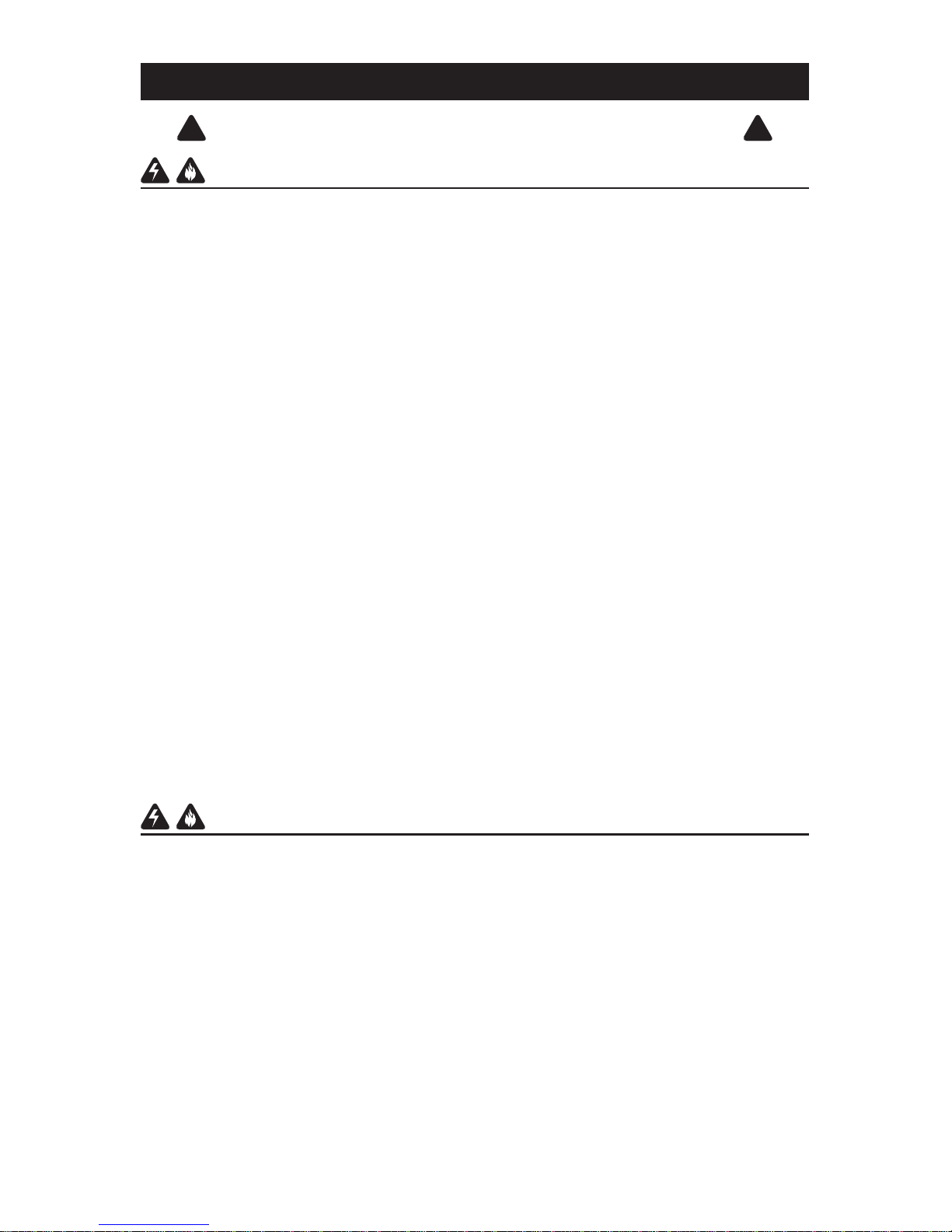
NON-DUCTED
RECIRCULATION FILTERS
INSTALLATION
Non-ducted Recirculation
1. Purchase a non-ducted recirculation filters
(B03300502) from your dealer.
2. Install the filters: push the filter against the
spring and rotate it up.
NON-DUCTED
RECIRCULATION FILTERS
MAINTENANCE
Proper maintenance of the Range Hood will
assure proper performance of the unit.
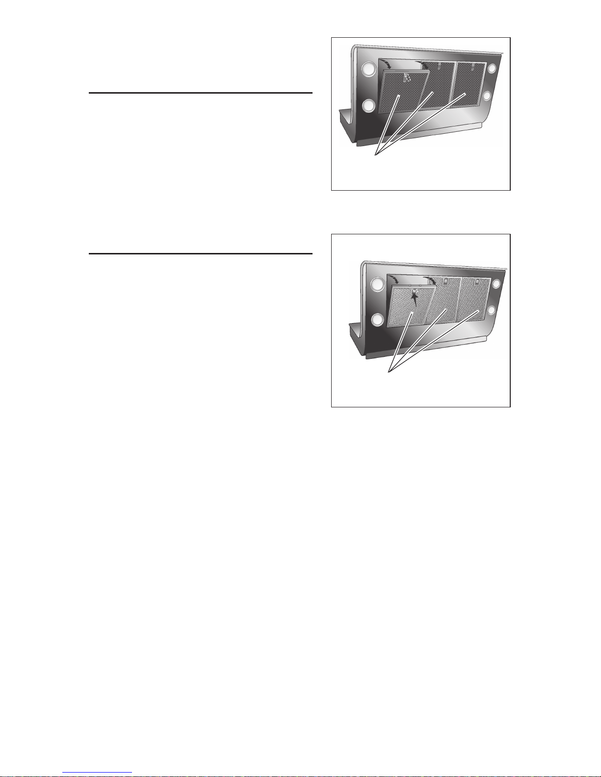
Grease Filters
The grease filters must be cleaned
approximately once every 30 hours of
operation (when the icon D1 goes on).
Use a warm detergent solution. Grease filters
is dishwasher safe.
Remove the filters: pull the handle outside
and unlock the filter.
Non-ducted Recirculation Filters
The non-ducted recirculation filters should be changed whenever the icon D10
starts blinking (i.e. every 120 hours of operation).
To remove the filters, pushing them against the spring and rotating down.
Hood Cleaning
Cleaning tips:
O Warm water with mild detergent is all that is usually needed.
O Follow all cleaning by rinsing with clear water. Wipe dry with a clean, soft cloth to
avoid water marks.
O DO NOT allow deposits to remain for long periods of time.
O DO NOT use ordinary steel wool or steel brushes.
O DO NOT allow salt solutions, disinfectants, bleaches, or cleaning compounds to
remain in contact for extended periods. Many of these compounds contain chemicals which may be harmful. Rinse with water after exposure and wipe dry with a
clean cloth.
GREASE FILTERS
Page 6
- 6 -
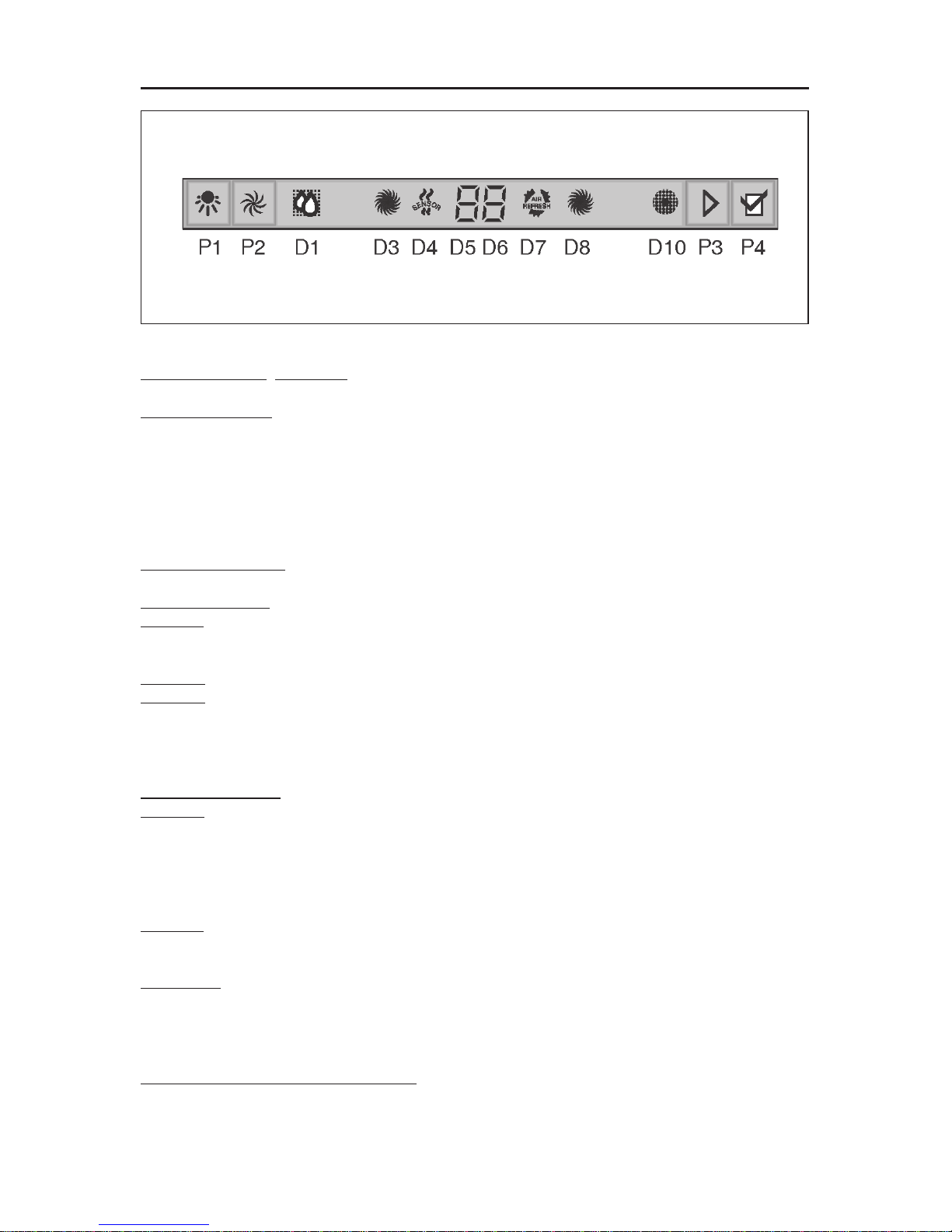
OPERATION
Controls
Push button P1: LIGHTS. Push the button once to turn the lights ON - push a second
time to turn the lights ON to a brighter level - push a third time to turn the lights OFF.
Push button P2: MOTOR: Switch on and off the motor. Switch on the motor to the
latest used speed and if pressed different times changes the speed in a cyclic way
(1,2,3,4,1,2…..) The speed set is visualized by the icon D5 and simultaneously the
icon D8 switches on ( the speed of the rotational movement is proportional to the
speed ). To the maximum speed the icon D8 switches off and the icon D3 switches
on.
To switch off the motor, press the push button P2 for about 2 seconds (the set speed
is memorized).
Push button P3: Switch on and off the functions D4(SENSOR) and/or D7 (Air
Refresh).
Push button P4: Reset grease filters and non-ducted recirculation filters.
Icon D1: GREASE FILTERS. It switches on when the grease filter must be cleaned
(after about 30 hours of working). One time the grease filters is cleaned, to make
the hours calculation start again, press the push button P4.
Icon D3 : MAXIMUM SPEED. Is activated only when the maximum speed is set.
Icon D4: SENSOR: To activate the sensor function, press the push button P3. To
disconnect the sensor, repeat the same operation. When the sensor activated, the
hood switches on automatically in the presence of any kinds of odours or vapours,
smokes or heat, caused by the cooking process and also in the presence of possible
and anomalous gas emissions in environment.
Icons D5 and D6: DISPLAY. Shows the set speed. Shows the sensor sensitivity.
Icon D7: AIR REFRESH: To start the function Air refresh, press the button P3 (the
icon goes on);
To disconnect the function Air refresh, repeat the same operation. The function Air
Refresh activates only if the motor is not working. Starting the function Air Refresh,
the hood recycles the air in the environment in perfect silence, starting every 50
minutes (for 10 minutes, at the first speed).
Icon D8 : ENGINE ON. The icon switches on when the engine is at the first, second
or third speed. To the fourth speed, the icon switches off and the icon starts working
to the maximum speed (icon D3).
Icon D10: NON -DUCTED RECIRCULATION FILTERS (For the non-ducted
recirculation hood). It switches on when it is time to replace the non-ducted
recirculation filters (after about 120 working hours). One time the non-ducted
recirculation filters is replaced, to make the hours calculation start again press the
button P4.
Modification of sensor sensitivity:
Simultaneously press push button P3 and P4 (the sensor’s sensitivity index will
appear on the display D5); press the push button P3 to change the sensor’s
sensitivity (1 : minimum sensitivity / 9: maximum sensitivity). Press the push button
P4 to confirm (or is confirmed automatically after 5 seconds).
Page 7
- 7 -
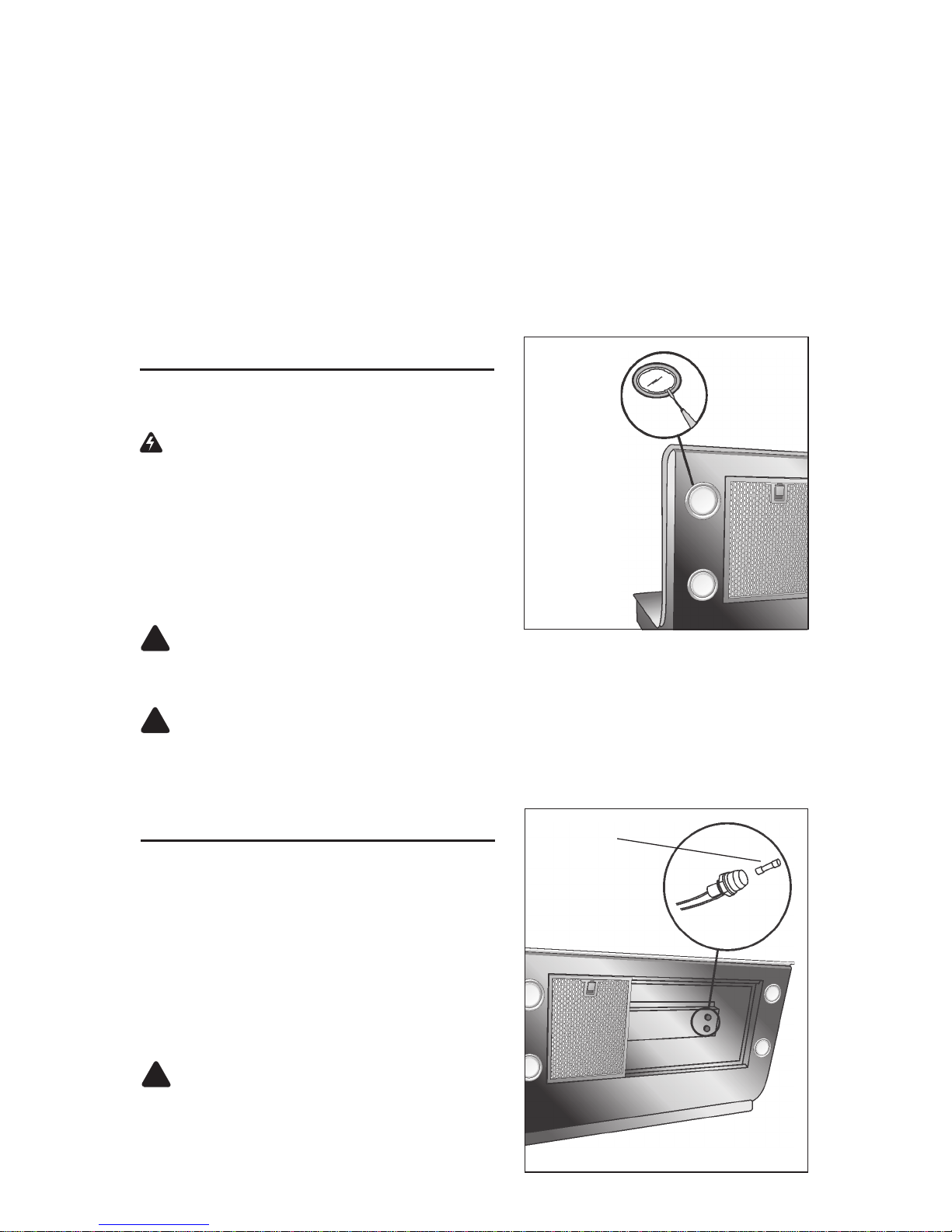
FUSE REPLACEMENT
IF LIGHTS FAIL TO OPERATE, DISCONNECT POWER AT THE SERVICE ENTRANCE. CHECK THE FUSE AND REPLACE IF NECESSARY.
1. Remove the grease filters.
2. Unscrew the cap from the fuse holder
and remove the fuse.
3. Replace the fuse with the same size and
amperage (5 x 20mm, 4 amp, 125 volt).
!
CAUTION: Use a fuse greater than 4
amps may damage the transformer.
4. Reinstall the fuse holder cap.
5. Reconnect power at the service entrance.
FUSE
HALOGEN BULBS
This range hood requires four halogen bulbs
(Type T3, 12Volt, 20Watt Max, G-4 Base).
WARNING: Always switch off the elec-
trical supply before carrying out any operation on the appliance.
To change bulbs:
1. Open the cover by prying from the proper
slots.
2. Remove the bulb by pulling sideways. (DO
NOT ROTATE).
!
CAUTION: Bulb may be hot.
3. Replace with Type T3, 12Volt, 20 Watt Max, G-4 Base halogen bulb. Do not touch
replacement bulb with bare hands!
!
CAUTION: Use of bulbs greater than 20 watts will cause the fuse to open.
HEAT SENTRY™
Your hood is equipped with a HEAT SENTRY™ thermostat. This thermostat is a
device that will turn on or speed up the blower if it senses excessive heat above
the cooking surface.
1) If blower is OFF - it turns blower ON to HIGH speed.
2) If blower is ON at a lower speed setting - it turns blower up to HIGH speed.
When the temperature level drops to normal, the blower will return to its original
setting.
WARNING
The HEAT SENTRY thermostat can start the blower even if the hood is turned
OFF. When this occurs, it is impossible to turn the blower OFF with its switch.
If you must stop the blower, do it from the main electrical panel.
Page 8
- 8 -
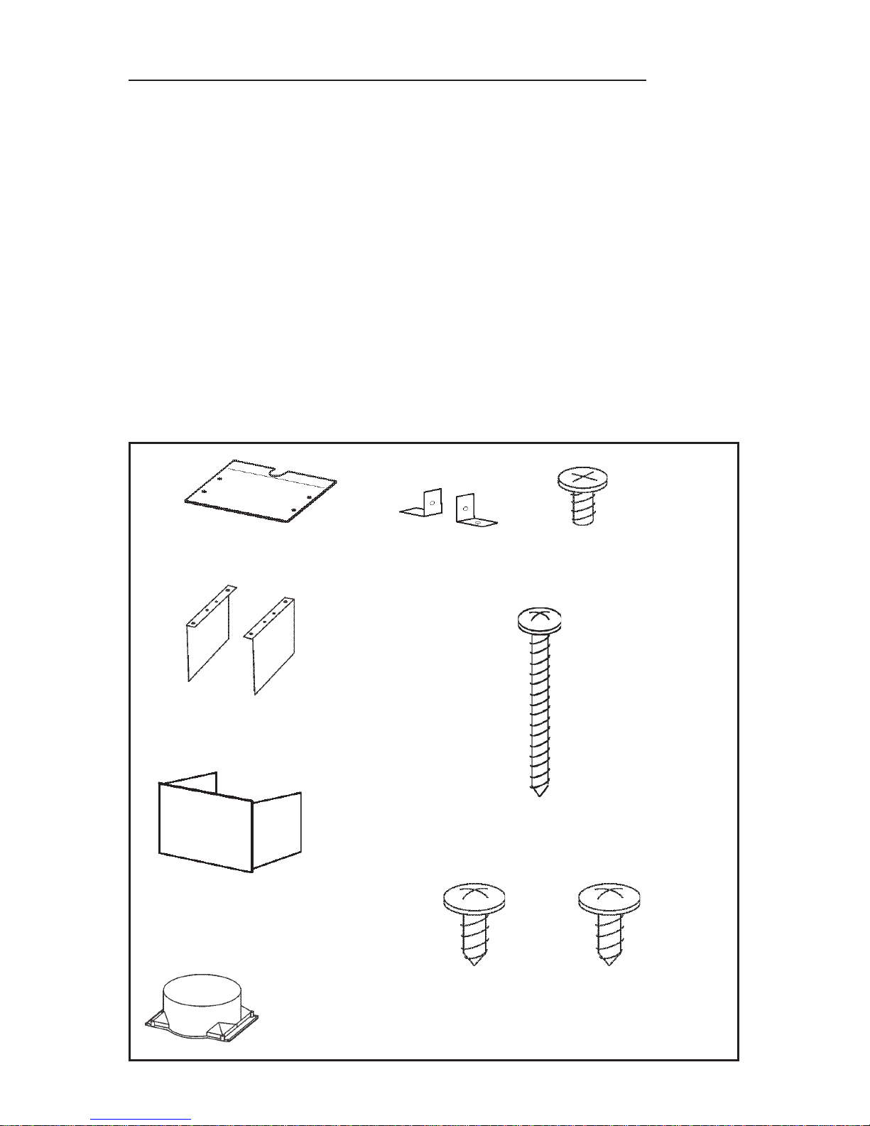
PREPARE THE HOOD
Unpack hood and check contents.
You should receive:
1 - Hood
1 - Decorative Flue
1 - Parts Bag (B080810765) containing:
1 - Cover
4 - Mounting Screws (4.8 x 38mm Pan Head)
4 - Mounting Screws (3.9 x 6mm Flat Head)
2 - Brackets
1 - Parts Bag (B080810621) containing:
1 - Discharge Collar
4 - Mounting Screws (3.9 x 9.5mm Pan Head)
4 - Mounting Screws (3.9 x 9.5mm Pan Head - Black)
2 - Small Brackets
1 - Installation Instructions
1 - Warranty Card
COVER
4 MOUNTING SCREWS
(4.8 x 38mm Pan Head)
4 MOUNTING
SCREWS (3.9
x 6mm Flat
Head)
DISCHARGE
COLLAR
4 MOUNTING
SCREWS (3.9
x 9.5mm Pan
Head)
2 BRACKETS
DECORATIVE
FLUE
2 SMALL
BRACKETS
4 MOUNTING
SCREWS (3.9
x 9.5mm Pan
Head - Black)
Page 9
- 9 -
23-5/8” TO 30” ABOVE
COOKING SURFACE
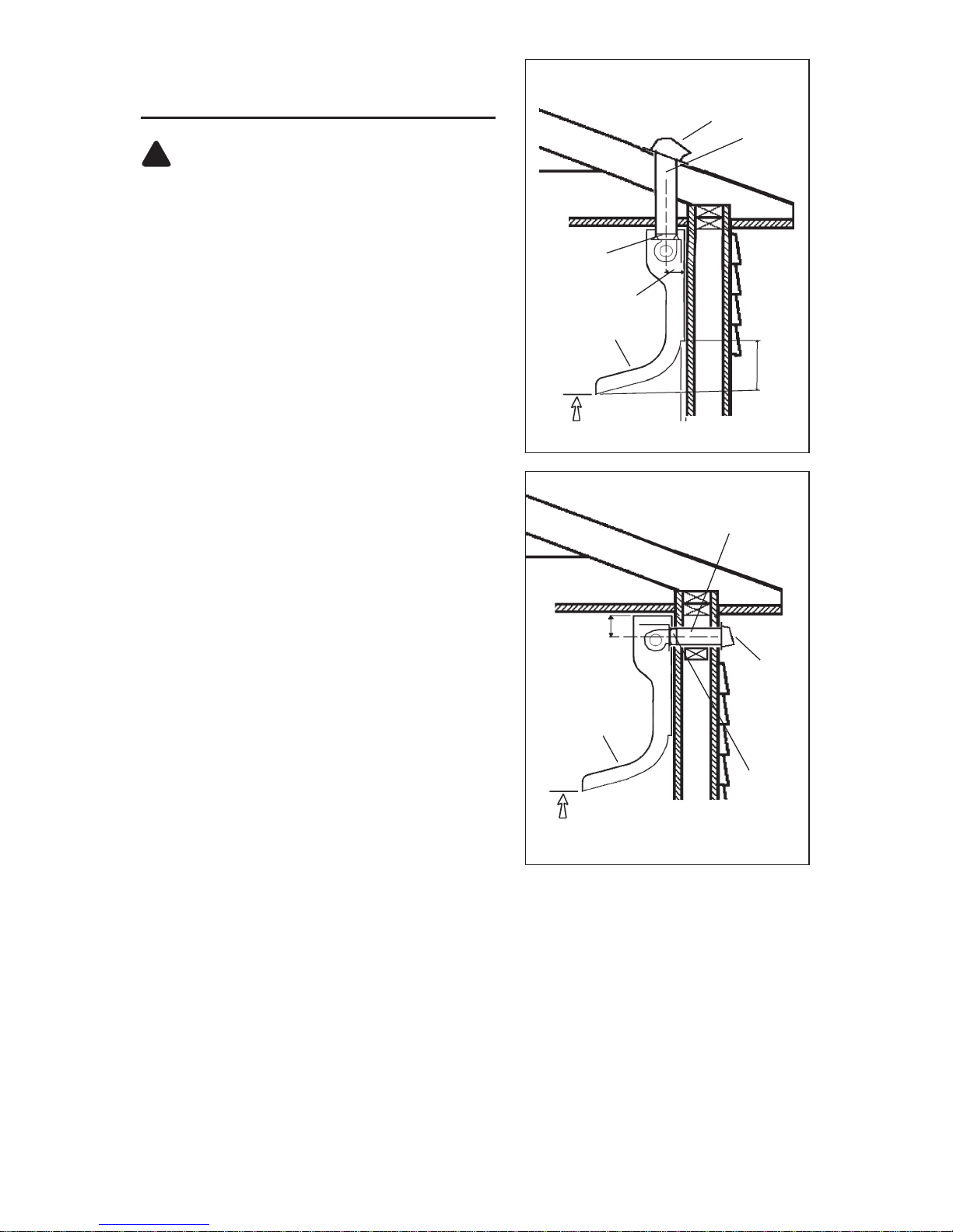
INSTALL THE DUCTWORK
(DUCTED HOODS ONLY)
!
WARNING: To reduce the risk of fire,
use only metal ductwork.
1. Decide where the ductwork will run
between the hood and the outside.
2. A straight, short duct run will allow the hood
to perform most efficiently.
3. Long duct runs, elbows, and transitions
will reduce the performance of the hood.
Use as few of them as possible. Larger
ducting may be required for best
performance with longer duct runs.
4. Install a roof or wall cap. Connect round
metal ductwork to cap and work back towards hood location. Use duct tape to seal
the joints between ductwork sections.
DUCTWORK ON THE WALL
HOOD
8-5/16”
WALL
CAP
8”
ADAPTER
ROUND DUCT
HOOD
DUCTWORK ON THE CEILING
ROOF CAP
ROUND
DUCT
23-5/8” TO 30” ABOVE
COOKING SURFACE
8” ADAPTER
4-3/4”
8-1/8”
1-1/4”
Page 10
- 10 -
INSTALL ELECTRICAL
WARNING : Electrical wiring must be
done by a qualified person(s) in
accordance with all applicable codes and
standards. This range hood must be
properly grounded. Turn off electrical
power at service entrance before wiring.
1. Remove the wiring box cover. Remove
a knockout from the wiring box.
2. Secure the conduit to the wiring box
through a conduit connector.
3. Make electrical connections. Connect
white to white, black to black and green to
green.
4. Replace wiring box cover and screws.
Make sure that wires are not pinched
between cover and box.
FIG. 1
WIRING BOX
Page 11

- 11 -
PREPARE THE HOOD
Note: Carefully remove the plastic
protective film from all exterior surfaces
of the hood and decorative flue, prior to
final installation.
To avoid demage while forwarding the
applicance has been locked by means of
four screws to a laminboard panel on the
bottom of the packing.
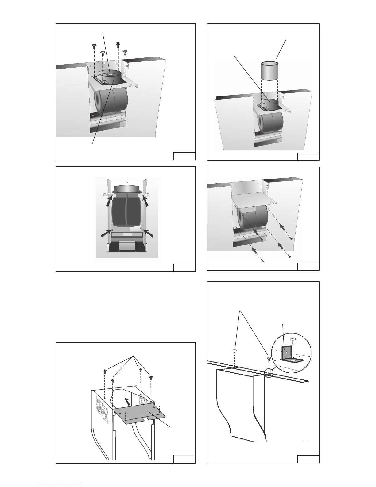
To separate the hood from the panel:
a. Disassemble the central block: rotate the
block outside softly (Fig. 2).
b.Remove the 4 screws (Fig. 3).
Ducted configuration
1. Fit the 2 brackets on the central block in
such a way that the two slots are plugged.
Each bracket must be fixed with (2) 3.9 x 6
mm mounting screws (Fig. 4).
2. Attach the discharge collar onto the hood
(Fig. 5); it must be attached by means of 4
mounting screws (3,9x9,5 mm Pan Head).
3. Remove the tape located on the damper
(Fig. 5).
4. Attach an adequate length of 8” round
steel ducting to the range hood discharge
collar (Fig. 6).
Duct tape all joints to make them secure
and air tight.
5. If the ductwork is placed on the wall (and
not on the ceiling), read the following
instructions:
- disassemble the motor block (included
the plate where it is fixed) unscrewing the
4 screws (Fig. 7).
- rotate motor block in order to have the
duct connector toward the wall.
- use the same screws to fix the motor
block in the new position (Fig. 8).
CENTRAL BLOCK
FIG. 2
FIG. 4
BRACKETS
MOUNTING SCREWS
(3.9x6mm)
FIG. 3
Page 12
- 12 -
FIG. 5
DISCHARGE COLLAR
REMOVE THE TAPE
8” DIAMETER
DUCT
DISCHARGE
COLLAR
FIG. 6
FIG. 7
FIG. 8
Ductfree configuration
Assemble the issued cover using 4 mounting
screws (3.9x6mm) - Fig. 9.
Ducted and Non-ducted configuration
For 9’ or 10’ ceilings, mount the the (2) small
brackets of the decorative flue with (2)
mounting screws (3.9x9.5mm - Black). Fig.10
COVER
MOUNTING SCREWS
(3.9x6mm)
FIG. 9
SMALL
BRACKETS
MOUNTING SCREWS
(3.9x9.5mm - Black)
FIG.10
Page 13
- 13 -
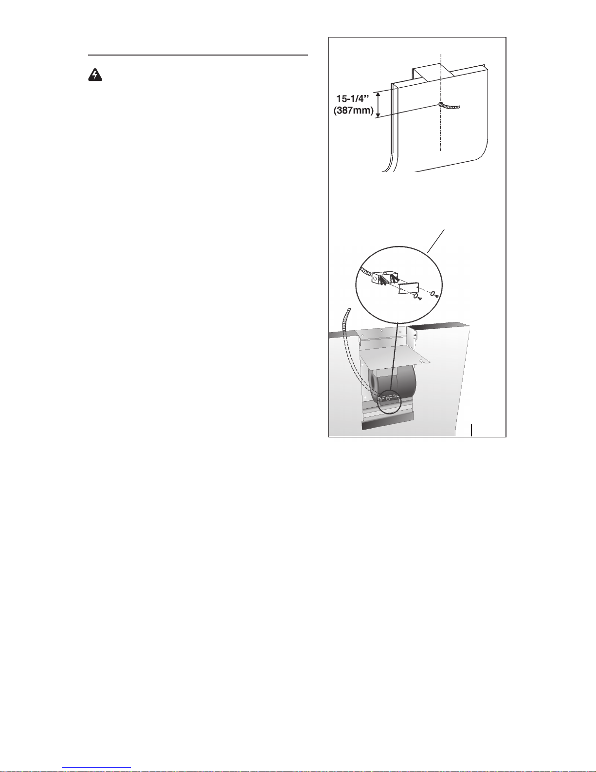
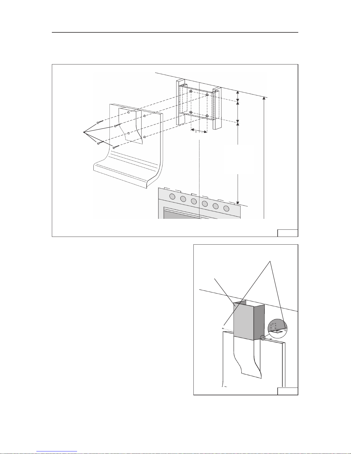
INSTALL THE HOOD
Note: at least 3 people will be required to mount the hood.
1. Make on the wall 4 holes (D. 8mm), according to the measures indicated in the
Fig. 11.
FIG.11
2. Secure the hood with (4) mounting screws
(4.8x38mm).
3. Make the electrical connection (see
“Install Electrical”).
4. Reassemble the central block.
5. For 9’ or 10’ ceilings, mount the decorative
flue. For 9’ ceilings, the decorative flue is
supplied. For 10’ ceilings, purchase a
decorative FLUE KIT from your dealer.
Secure the flue with (2) mounting screws
(3.9x9.5mm - Black). Fig. 12.
7-7/8”
1-1/8”
13-15/16”
45” to
51-3/8”
above
cooktop
MOUNTING
SCREWS
(4.8x38mm)
45" = bottom of hood 23-5/8" above cooktop
51-3/8" = bottom of hood 30" above cooktop
FIG.12
DECORATIVE
FLUE
MOUNTING SCREWS
(3.9x9.5mm - Black)
8’ CEILING
Page 14

- 14 -
WARRANTY
BROAN ONE YEAR LIMITED WARRANTY
Broan warrants to the original consumer purchaser of its products that such products will be free from defects in materials
or workmanship for a period of one year from the date of original purchase. THERE ARE NO OTHER WARRANTIES,
EXPRESS OR IMPLIED, INCLUDING, BUT NOT LIMITED TO, IMPLIED WARRANTIES OR MERCHANT ABILITY OR
FITNESS FOR A PARTICULAR PURPOSE.
During this one-year period, Broan will, at its option, repair or replace, without charge, any product or part which is found to
be defective under normal use and service.
THIS WARRANTY DOES NOT EXTEND TO FLUORESCENT LAMP STARTERS, TUBES, HALOGEN AND
INCANDESCENDT BULBS. This warranty does not cover (a) normal maintenance and service or (b) any products or parts
which have been subject to misuse, negligence, accident, improper maintenance or repair (other than by Broan), faulty
installation or installation contrary to recommended installation instructions.
The duration of any implied warranty is limited to the one-year period as specified for the express warranty. Some states do
not allow limitation on how long an implied warranty lasts, so the above limitation may not apply to you.
BROAN’S OBLIGATION TO REPAIR OR REPLACE, AT BROAN’S OPTION, SHALL BE THE PURCHASER’S SOLE AND
EXCLUSIVE REMEDY UNDER THIS WARRANTY. BROAN SHALL NOT BE LIABLE FOR INCIDENTAL, CONSEQUENTIAL OR SPECIAL DAMAGES ARISING OUT OF OR IN CONNECTION WITH PRODUCT USE OR PERFORMANCE.
Some states do not allow the exclusion or limitation of incidental or consequential damages, so the above limitation or
exclusion may not apply to you.
This warranty gives you specific legal rights, and you may also have other rights, which vary from state to state. This warranty
supersedes all prior warranties.
To qualify for warranty service, you must (a) notify Broan at the address stated below or telephone: 1-800-637-1453, (b) give
the model number and part identification and (c) describe the nature of any defect in the product or part. At the time of requesting
warranty service, you must present evidence of the original purchase date.
BEST BY BROAN, P.O. Box 140 Hartford, Wisconsin 53027
Page 15

- 15 -
LISEZ ET CONSERVEZ CES INSTRUCTIONS
AVERTISSEMENTS
POUR REDUIRE LES RISQUES D’INCENDIE, DE DECHARGES ELECTRIQUES OU
DE DOMMAGES AUX PERSONNES, OBSERVEZ LES INSTRUCTIONS SUIVANTES:
1. N’utilisez cet appareil que comme cela est indiqué par le constructeur. Si vous avez des
problèmes, contactez le fabriquant à l’adresse ou au numéro de téléphone indiqués dans
la garantie.
2. Avant de pourvoir à l’entretien ou au nettoyage de votre appareil, éteignez-le au tableau
des commandes ou bloquez le tableau des commandes afin d’éviter de le mettre en marche
accidentellement. Si vous ne pouvez pas bloquer le système permettant d’éteindre votre
appareil, appliquez un avertissement extérieur d’une façon sure, comme par exemple un
panneau, sur le tableau des commandes.
3. L’assemblage et la connexion électrique doivent être faits par des personnes qualifiées
en respectant les normes et règlements en vigueur, y compris les normes et règlements
concernant les possibilités d’incendie.
4. Il est indispensable qu’il y ait suffisamment d’air pour que la combustion et l’évacuation des
gaz à travers le tuyau du brûleur du combustible ait lieu sans retour de flamme. Suivez
les indications données par le fabricant du brûleur ainsi que les normes de sécurité comme
celles qui sont publiées par l’Association Nationale pour la Protection contre les Incendies
National Fire Protection Association (NFPA) et la American Society for Heating, Refrigeration
and Air Conditioning Engineers (ASHRAE), et les autorités locales en matière de normes.
5. Quand vous coupez ou percez des trous dans le mur ou le plafond, n’abîmez pas les fils
électriques ou autres.
6. Le ventilateur canalisé doit toujours évacuer l’air vers l’extérieur.
7. N’utilisez pas cet appareil avec un appareil contrôlant la vitesse à état solide.
8. Afin de diminuer tout risque d’incendie n’utilisez que des conduits en métal.
9. Votre appareil doit être relié à la terre.
ATTENTION - POUR REDUIRE LES RISQUES D’INCENDIE DES MATIERES GRASSES
QUI SONT EN TRAIN DE CUIRE:
A . Ne laissez jamais ni vos éléments chauffants, ni vos casseroles ou poêles sur le feu
sans les contrôler si vous réglez l’apport de chaleur sur une position élevée. Si vos
casseroles ou poêles débordent cela provoque de la vapeur et des éclaboussures de
graisse qui peuvent prendre feu. Chauffez les huiles lentement à feu bas ou moyen.
B. Faites toujours fonctionner votre hotte quand vous cuisez à des températures élevées
ou quand vous cuisinez des plats flambés. (par ex. crêpes Suzette, Cerises “Jubilé”,
Steack au poivre flambé).
C. Nettoyez régulièrement les ailes de vos ventilateurs. Ne permettez pas que la graisse
s’accumule sur le ventilateur ou sur le filtre.
D. Utilisez des casseroles de taille appropriée. Utilisez toujours des ustensiles de cuisson
dont la taille est appropriée à la surface de votre élément de cuisson.
AVERTISSEMENTS
POUR REDUIRE LES RISQUES DE DOMMAGES AUX PERSONNES AU CAS OÙ VOTRE
CUISINIERE PRENDRAIT FEU, OBSERVEZ LES INSTRUCTIONS SUIVANTES:*
1. ETEINDRE LES FLAMMES à l’aide d’un couvercle le plus hermétique possible, une
plaque à gâteaux, ou un plateau en métal, puis éteindre le brûleur. ATTENTION à NE
PAS VOUS BRÛLER. Si les flammes ne s’éteignent pas immédiatement, SORTEZ ET
APPELEZ LES POMPIERS.
2. NE PRENEZ JAMAIS EN MAIN UNE POÊLE OU UNE CASSEROLE QUI A PRIS FEU
- Vous pourriez vous brûler.
3. N’UTILISEZ PAS D’EAU, ni torchons ou serviettes mouillés - vous provoqueriez une
violente explosion de vapeur.
SEULEMENT POUR UTILISATION DOMESTIQUE
!
!
Page 16

- 16 -
4. Utilisez un extincteur SEULEMENT si:
A. Vous savez que vous avez un extincteur Classe ABC, et vous en connaissez déjà le
mode d’emploi.
B. Ce n’est pas un très gros incendie et qu’il se limite à l’endroi où il a explosé.
C. Vous êtes en train d’avertir les pompiers.
D. Vous avez la possibilité d’essayer d’éteindre l’incendie en ayant le dos tourné vers
une issue.
* D’après les “Suggestions concernant la Sécurité contre les incendies des cuisines”
publiées par NFPA.
ATTENTION
1. Pour réduire tout risque d’incendie et pour évacuer correctement l’air, assurez-vous de
prévoir un conduit de ventilation extérieur. Ne videz pas l’air dans les espaces limités
par des murs ou des plafonds, les combles, les passages étroits ou les garages.
2. Faites très attention quand vous utilisez des produits de nettoyage ou des détergents.
3. Évitez d’utiliser des aliments pouvant s’enflammer sous la Range Hood.
4. N’utilisez cet appareil que pour une ventilation générale. Ne l’utilisez pas pour évacuer
des matières ou des vapeurs dangereuses ou qui peuvent exploser.
5. Pour éviter de causer des dommages au moteur et de rendre les rotors bruyants et/ou
non équilibrés, évitez que les sprays pour murs secs, la poussière de construction
entrent en contact avec la partie électrique.
6. Le moteur de votre hotte a un thermostat qui éteindra automatiquement le moteur s’il est
surchauffé. Le moteur se remettra en marche lorsqu’il se sera refroidi. Si le moteur
continue à s’éteindre et à se remettre en marche, faites vérifier votre hotte.
7. Pour mieux capturer les impuretés de cuisine, le bas de votre hotte devrait être à une
distance minimum de 23-5/8” et à une distance maximum de 30” au-dessus du plan de
cuisson.
8. Vu que cette hotte est grande et lourde, il est recommandé de confier l’installation de
cette hotte à 3 personnes.
9. Ce produit est doté d’un thermostat qui active automatiquement le moteur. Pour
réduire le risque de dommages et éviter l’activation accidentelle, positionner l’interrupteur
du panneau de service sur la position OFF et bloquer le panneau de service ou mettre
un avertissement externe, par exemple une plaquette.
10 . Utiliser uniquement avec un kit de connexion pour alimentation homologué.
11 . Nous vous recommandons de lire l’étiquette indiquant les caractéristiques de votre
hotte pour de plus amples informations et exigences.
!
Page 17

- 17 -
ASSEMBLAGE DES FILTRES A
CHARBON
Modèles recyclant l’air
1. Procurez-vous les filtres à charbon
(B03300502) chez votre fournisseur.
2. Installer les filtres: pousser le filtre contre
le ressort et le tourner vers le haut.
FILTRES A CHARBON
ENTRETIEN
Un bon entretien de votre hotte garantira
une excellente performance.
Filtres anti-graisse :
Les filtres anti-graisse doivent être
nettoyés environ toutes les 30 heures de
fonctionnement (lorsque l’icône D1
s’allume). Utilisez une solution contenant
un détergent tiède. Les filtres anti-graisse
peuvent être lavés au lave-vaisselle.
Enlevez les filtres: tirer la poignée vers
l’externe et décrocher le filtre.
Filtres à charbon :
Les filtres à charbon (pour modèles recyclant l’air) doivent être remplacés toutes les fois
que l’icône D10 s’allume (c’est-à-dire toutes les 120 heures de fonctionnement).
Enlever les filtres à charbon en les poussant contre le ressort et les faisant tourner
vers le bas.
Nettoyage de votre hotte
Conseils pour le nettoyage:
O Eau tiède additionnée d’un détergent doux est tout ce qui est normalement
nécessaire.
O Après chaque nettoyage, rincez bien à l’eau claire. Essuyez avec un chiffon
propre et doux afin d’éviter les taches d’eau.
O NE LAISSEZ PAS les taches trop longtemps.
O N’UTILISEZ PAS de laines d’acier ordinaires ou des brosses en acier.
O NE PERMETTEZ PAS que des solutions salées, des désinfectants, des
blanchissants ou des produits nettoyants restent en contact pendant longtemps.
Beaucoup de ces produits contiennent des produits chimiques qui pourraient
causer des dommages. Rincez à l’eau immédiatement s’ils entrent en contact et
essuyez avec un chiffon humide.
FILTRES ANTI-GRAISSE
Page 18

- 18 -
FONCTIONNEMENT
Commandes
Touche P1: ECLAIRAGE. En pressant 1 fois la touche, la lumière s’allume au 1
er
niveau; en pressant 2 fois la touche, la lumière du 2
ème
niveau s’allume (éclairage
plus intense); en pressant encore une fois la touche, la lumière s’éteint.
Touche P2: MOTEUR. Active/Désactive le moteur. Active le moteur à la dernière
vitesse utilisée, et si on la presse à plusieurs reprises elle change la vitesse de façon
cyclique (1, 2, 3, 4, 1, 2....). La vitesse établie est visualisée par l’icône D5 et, en
même temps, l’icône D8 s’active (la vitesse du mouvement rotatif est proportionnelle
à la vitesse ). L’icône D8 se désactive et l’icône D3 s’active à la vitesse maximum.
Pour arrêter le moteur presser la touche P2 pendant 2 secondes environ (on met
en mémoire la vitesse établie).
Touche P3: Sélectionne/Déselectionne les fonctions D4 (CAPTEUR) et/ou D7 (Air
Refresh).
Touche P4: Reset filtres à graisse et filtres à charbon.
Icône D1: FILTRES À GRAISSE. Elle s’allume quand il est temps de nettoyer le/
s filtre/s à graisse (après environ 30 heures de fonctionnement de la hotte). Une
fois nettoyes les filtres à graisse, presser la touche P4 pour faire repartir le
comptage.
Icône D3: VITESSE MAXIMUM. Elle s’active seulement quand la vitesse maximum
est établie.
Icône D4: CAPTEUR. Pour activer la fonction capteur, presser la touche P3. Pour
désactiver le capteur, répéter la même opération. Avec le capteur activé, la hotte
s’actionne automatiquement en présence de n’importe quel type d’odeur, vapeur,
fumée ou chaleur provoquée par le processus de cuisson et même en présence
d’éventuelles fuites de GAZ dans l’environnement.
Icônes D5 et D6: DISPLAY. Il visualise la vitesse établie. Il visualise la sensibilité
du capteur.
Icône D7: AIR REFRESH. Pour activer la fonction Air Refresh, presser la touche P3
jusqu’à ce que l’icône s’allume. Pour désactiver la fonction Air Refresh répéter la
même opération.
La fonction Air Refresh s’active seulement si le moteur n’est pas en marche. En
activant la fonction Air Refresh, la hotte change l’air dans le local dans un silence
absolu, en s’actionnant toutes les 50 minutes (pour une durée de 10 minutes, à la
première vitesse).
Icône D8: MOTEUR ON. L’icône s’allume quand le moteur est à la première,
seconde ou troisième vitesse. A la quatrième vitesse, l’icône s’éteint et l’icône
relative à la vitesse maximum s’active (icône D3).
Icône D10: FILTRES À CHARBON (pour la hotte recyclant l’air). Elle s’allume quand
il est temps de remplacer les filtres à charbon (après environ 120 heures de
fonctionnement de la hotte). Une fois les filtres à charbon remplacés, pour faire
repartir le comptage des heures presser la touche P4.
Modification de la sensibilité du capteur:
appuyer en même temps sur les touches P3 et P4 (l’afficheur D5 visualise
l’indice de sensibilité du capteur); appuyer sur la touche P3 pour changé la
sensibilité du capteur (1 : sensibilité minimum / 9: sensibilité maximum).
Page 19

- 19 -
FUSIBLE
REMPLACEMENT FUSIBLE
SI LES AMPOULES NE FONCTIONNENT
PAS, DÉBRANCHEZ L’ALIMENTATION À
L’ENTRÉE DE SERVICE. CONTRÔLEZ LE
FUSIBLE ET REMPLACEZ-LE SI
NÉCESSAIRE.
1. Retirez les filtres de graisse.
2. Dévissez la protection du support de
fusible et retirez le fusible.
3. Remplacez le fusible par un autre de
même taille et de même intensité (5 x
20 mm, 4 amp, 125 volts).
!
ATTENTION : L’utilisation d’un fusible de plus de 4 amps peut endommager
le transformateur.
4. Replacez la protection du support de fusible.
5. Rebranchez l’alimentation à l’entrée de service.
AMPOULES HALOGENES
Ce modèle de hotte veut quatre (4) ampoules
halogènes (Type T3, 12Volt, 20 Watt Max, G4 Base).
ATTENTION: avant de procéder à
quelconque opération, débranchez
l’appareil.
Pour changer les ampoules:
1. Ouvrez le couvercle en faisant levier grâce
aux fissures prévues à cet effet.
2. Retirez l’ampoule en tirant latéralement.
(NE LA FAITES PAS TOURNER).
ATTENTION: l’ampoule peut être chaude!
3. Remplacer par une ampoule ayant les mêmes caractéristiques (T3, 12Volt, 20
Watt Max, G-4 Base). Ne touchez pas l’ampoule neuve de vos mains nues.
ATTENTION: L’utilisation d’ampoules de plus de 20 watts provoquera
l’ouverture du fusible.
Appuyer la touche P4 pour confermer (ou est confermé automatiquement
depuis 5”).
HEAT SENTRY
MC
Votre hotte est munie d’un thermostat HEAT SENTRYMC. Ce thermostat est un dispositif
qui actionnera ou augmentera la vitesse du ventilateur s’il détecte une chaleur
excessive au-dessus de la surface de cuisson.
1) Si le ventilateur n’est pas en marche - il actionnera le ventilateur en haute vitesse.
2) Si le ventilateur fonctionne en basse vitesse - le ventilateur tournera en haute
vitesse.
Lorsque la température revient à la normale, le ventilateur retourne à sa vitesse
d’origine.
AVERTISSEMENT
Le thermostat HEAT SENTRY
MC
peu actionner la hotte même si la hotte est
arrêtée. Si tel est le cas, il est impossible de l’arrêter avec l’interrupteur. Si vous
devez arrêter le ventilateur, faites-le à partir du panneau électrique principal.
Page 20

- 20 -
PREPAREZ LA HOTTE
Enlever la hotte dans l’emballage et controller le contenu.
Vous devez recevoir :
1 - Hotte
1 - Tuyau décoratif
1 - Sachet (B080810765) avec:
1 - Couvercle
4 - Vis d’assemblage (4.8 x 38mm Tête ronde)
4 - Vis d’assemblage (3.9 x 6mm Tête plate)
2 - Brides
1 - Sachet (B080810621) avec:
1 - Collier d’evacuation
4 - Vis d’assemblage (3,9 x 9,5mm Tête ronde)
4 - Vis d’assemblage (3,9 x 9,5mm Tête ronde - Noire)
2 - Petites Brides
1 - Instructions pour l’installation
1 - Garantie
COUVERCLE
4 VIS D’ASSEMBLAGE
(4,8 x 38mm Tête ronde)
4 VIS
D’ASSEMBLAGE
(3.9 x 6mm Tête
plate)
COLLIER
D’EVACUATION
4 VIS
D’ASSEMBLAGE
(3,9 x 9,5 mm
Tête ronde)
2 BRIDES
TUYAU
DECORATIF
2 PETITES
BRIDES
4 VIS
D’ASSEMBLAGE
(3,9 x 9,5 mm
Tête ronde Noire)
Page 21

- 21 -
INSTALLATION DU
SYSTEME D’EVACUATION
(UNIQUEMENT POUR LES HOTTES
AVEC TUYAU D’EVACUATION)
ATTENTION: Pour réduire les risques
d’incendie, n’utilisez que des tuyaux en
métal.
1. Décidez où le tuyau rond doit être installé,
entre votre hotte et l’extérieur.
2. Un tuyau droit et court permettra à votre
hotte de fonctionner d’une façon plus efficace.
3. Un tuyau long avec des coudes et des
transitions réduira le bon fonctionnement
de votre hotte. En utiliser le moins possible.
Pour de longues utilisations, il faut un
tuyau d’évacuation d’air ayant un diamètre
plus large.
4. Installez un couvercle sur le toit ou au mur.
Reliez un tuyau en métal rond au
couvercle et faites-le aller jusqu’à
l’emplacement de votre hotte. Rendez les
jonctions du tuyau hermétiques au moyen
d’un ruban pour tuyaux.
HOTTE
8-5/16”
(21.1cm)
8” (20cm)
ADAPTATEUR
SYSTEME D’EVACUATION SUR LE PLAFOND
8” (20cm)
ADAPTATEUR
4-3/4”
(12cm)
DE 23-5/8” (60cm) À
30” (76.2cm) AU-
DESSUS DU PLAN
DE CUISSON
SYSTEME D’EVACUATION SUR LE MUR
HOTTE
COUVERCLE DU TOIT
TUYAU
ROND
COUVERCLE
DU MUR
TUYAU
ROND
DE 23-5/8” (60cm) À 30”
(76.2cm) AU-DESSUS DU
PLAN DE CUISSON
8-1/8”
(206mm)
1-1/4”
(31.42mm)
Page 22

- 22 -
INSTALLATION ELECTRIQUE
AVERTISSEMENT:Les branchements
électriques doivent être réalisés par une
personne qualifiée, conformément à tous
les codes et règlements applicables.
Cette hotte doit être correctement
raccordée à la terre. Coupez
l’alimentation à l’entrée de service avant
de procéder au câblage.
1. Enlevez le couvercle de la boîte de
connexion électrique. Ouvrez un trou de
la boîte de connexion électrique.
2. Fixer le “conduit” au boîtier de
connexion à l’aide d’un connecteur
approprié pour ce “conduit”.
3. Faites le raccordement électrique. Reliez
le blanc au blanc, le noir au noir et le vert
au vert.
4. Remettez le couvercle de la boîte de
connexion et les vis. Assurez-vous que
les fils se sont pas coincés entre le
couvercle et la boîte.
BOÎTE DE CONNEXION
ÉLECTRIQUE
FIG. 1
Page 23

- 23 -
PRÉPARATION DE LA HOTTE
Remarque :
retirez précautionneusement le film
protecteur des surfaces extérieures et
du tuyau décoratif avant de terminer
l’installation.
Pour éviter de causer des dommages pedant
le transport, l'appareil a été fixé, au moyen
de quatre vis à un panneau d'aggloméré
placé au fond de la boîte d'emballage.
Pour séparer la hotte du panneau, faites
ainsi:
a.Démonter le bloc central: faire rouler
délicatement le bloc vers l’extérieur (Fig.2).
b.Enlever le 4 vis (Fig. 3).
Configuration avec tuyau d’evacuation
1. Monter les 2 brides sur le bloc central
de telle sorte que les ouvertures soient
obturées. Chaque bride doit être fixée à
l’aide de (2) vis d’assemblage 3.9x6 mm
(Fig. 4).
2. Fixez le collier d’évacuation au haut de
votre hotte (Fig. 5); la fixation a lieu au
moyen des 4 vis d’assemblage (3,9 x
9,5mm Tête ronde).
3. Enlever le ruban positionné sur le clapet
(Fig. 5).
4. Attachez un conduit arrondi en acier
d’une longueur de 8" au collier
d’évacuation de la hotte (Fig. 6).
Reliez toutes les sections pour
empêcher le passage de l’air.
5. Si le conduit d’evacuation de l’air est
placé sur le mur (et non pas sur le
plafond), lire les instructions suivantes:
- démonter le bloc moteur (y compris la
plaque sur laquelle il est fixé) en dévissant
les 4 vis (Fig. 7).
- le tourner le bloc moteur de façon que le
collier d’evacuation soit orienté vers le
mur.
- utiliser les mêmes vis pour fixer le bloc
moteur dans la nouvelle position (Fig.8).
BLOC CENTRAL
FIG. 2
FIG. 4
BRIDES
VIS D’ASSEMBLAGE
(3.9x6mm)
FIG. 3
Page 24

- 24 -
COLLIER
D’EVACUATION
ENLEVER LE RUBAN
DIAMÈTRE DU
CONDUIT 8”
COLLIER
D’EVACUATION
FIG. 5
FIG. 6
FIG. 7
FIG. 8
Configuration recyclant l’air
Monter le couvercle en dotation en utilisant
4 vis d’assemblage (3.9x6mm) - Fig. 9.
Configuration avec tuyau d’evacuation
et recyclant l’air
Lorsque le plafond est de 9’ ou 10’, mountez les
2 petites brides du tuyau décoratif au moyens
de (2) vis d’assemblage (3.9x9.5mm - Noire).
Fig. 10.
FIG. 9
FIG.10
VIS D’ASSEMBLAGE
(3.9x9.5mm - Noire)
PETITES
BRIDES
COUVERCLE
VIS D’ASSEMBLAGE
(3.9x6mm)
Page 25

- 25 -
INSTALLATION DE LA HOTTE
Remarque : la hotte doit être installée par au moins 3 personnes.
1. Faites sur le mur 4 trous (D. 8mm), en respectant les mesures indiquées sur la
Fig. 11.
2. Fixez la hotte au moyen de (4) vis
d’assemblage (4.8x38mm).
3. Procéder au branchement électrique
(faire référence à la section “Installation
electrique”).
4. Remonter le bloc central.
5. Lorsque le plafond est de 9’ ou 10’, mountez
le tuyau décoratif. Pour plafond de 9’, le
tuyau décoratif è fournie. Pour plafon de
10’, procurez-vous un KIT de tuyau
décoratif chez votre fournisseur.
Fixez le tuyau décoratif au moyen des (2)
vis d’assemblage (3.9x9.5mm - noire).
Fig. 12.
7-7/8”
(200mm)
1-1/8”
(28mm)
13-15/16”
(354mm)
De
45”(1143mm)
à 51-3/8”(1305mm)
au-dessus du plan
de cuisson
VIS
D’ASSEMBLAGE
(4.8x38mm)
45" = si la distance entre la hotte et le plan de cuisson c’est de 23-5/8”(600mm).
51-3/8" = si la distance entre la hotte et le plan de cuisson c’est de 30”(762mm).
FIG.12
TUYAU
DECORATIF
VIS D’ASSEMBLAGE
(3.9x9.5mm - Noire)
FIG.11
PLAFOND
DE 8’
Page 26

- 26 -
GARANTIE BROAN LIMITÉE À UN AN
Broan garantit au consommateur-acheteur de ses produits que ces produits seront sans défauts concernant les matières
employées et concernant la fabrication pendant une période d’un an à partir de la date d’achat. IL N’Y A AUCUNE AUTRE
GARANTIE, EXPLICITE OU IMPLICITE, Y COMPRIS, MAIS NON PAS LIMITEE A, LES GARANTIES IMPLICITES OU
CONCERNANT LA CAPACITE COMMERCIALE OU LA CONVENANCE POUR TOUT BUT PARTICULIER. Pendant cette
période d’un an, Broan réparera ou remplacera, s’il le jugera nécessaire, gratuitement, tout article ou toute pièce qui résulteront
défectueux à condition qu’ils aient été utilisée et entretenu correctement.
CETTE GARANTIE NE S’ETEND PAS AUX INTERRUPTEURS DES NEON, NEON, LAMPES HALOGENES, AMPOULES
d”ILLUMINATION. Cette garantie ne couvre pas (a) l’entretien normal ni (b) tout article ou toute pièce qui aient subi une
utilisation erronée, une négligence, un accident, un entretien erroné ou une réparation (autre que de la part de Broan), une
installation défectueuse ou bien une installation ne respectant pas les instructions d’installation recommandées.
La durée de toute garantie implicite est limitée à un an comme cela est spécifié dans la garantie explicite. Quelques états ne
permettent pas de limites quant à la durée d’une garantie implicite, par conséquent la limitation indiquée ci-dessus peut ne pas
vous concerner.
L’OBLIGATION DE REPARER OU DE REMPLACER DE LA PART DE BROAN SERA LE SEUL ET EXCLUSIF REMEDE
DE L’ACHETEUR COUVERT PAR CETTE GARANTIE. BROAN NE SERA PAS RESPONSABLE DES DOMMAGES
ACCIDENTELS, CONSEQUENTIELS OU SPECIAUX DUS A L’UTILISATION DU PRODUIT OU A SA PERFORMANCE
OU EN ETANT LA CONSEQUENCE. Quelques états ne permettent pas l’exclusion ou la limitation des dommages accidentels
ou conséquentiels, par conséquent la limitation indiquée ci-dessus peut ne pas vous concerner. Cette garantie vous donne des
droits légaux spécifiques, et vous pouvez aussi avoir d’autres droits, qui varient d’Etat à Etat. Cette garantie dépasse toute
garantie précédente. Pour avoir droit à la garantie, vous devez (a) avertir la Maison Broan à l’adresse indiquée ci-dessous ou
téléphoner : 1-800-637-1453, (b) donner le numéro du modèle et l’identification de la pièce défectueuse et (c) décrire la nature
de tout défaut de l’article ou de la pièce. Au moment où vous demandez le service de garantie, vous devez présenter la preuve
d’achat avec la date.
BEST BY BROAN, P.O. Box 140 Hartford, Wisconsin 53027
GARANTIE
Page 27

- 27 -
LEA Y CONSERVE ESTAS INSTRUCCIONES
ADVERTENCIA
PARA EVITAR EL RIESGO DE INCENDIO, CORTOCIRCUITO O DAÑO PARA LAS
PERSONAS, OBSERVE ATENTAMENTE LAS SIGUIENTES NORMAS:
1. Use esta unidad solamente de la manera indicada por el fabricante; si tiene dudas,
póngase en contacto con éste a la dirección o teléfono indicados en la garantía.
2. Antes de hacer una revisión o de limpiar la unidad, desconéctela de la red para evitar
que se encienda de manera accidental. En el caso de que éste no pueda ser desactivado, se indicará nel panel de servicio.
3. El montaje y la instalación eléctrica debe hacerlos un técnico especializado siguiendo
las normas estándar e incluyendo aquellas de construcción anti incendio.
4. Necesita aire suficiente para una apropiada combustión y escape de gases a través del
tubo del depósito de quema de combustible. Para evitar que el humo aspirado vuelva a
la cocina, siga las directivas del fabricante y las normas estándar de siguridad así como
las normas publicadas por la Asociación de prevención de incendios (NFPA) y la Sociedad americana de especialistas en cale-facción, refrigeración y aire acondicionado y
además las normas de las autoridades locales.
5. Hacer un corte o un taladro en la pared o en el techo no debe dañar la instalación
eléctrica u otras instalaciones ocultas en la pared.
6. Los conductos ventiladores deben siempre desalojar al exterior.
7. No use esta unidad con dispositivo de control de la velocidad a estado sólido.
8. Para evitar el riesgo de incendio, use solamente conductos de metal.
9. Esta unidad tiene que ser conectada a tierra.
PARA EVITAR EL RIESGO DE FUEGO POR ALTO NIVEL DE GRASA:
A. Nunca abandone los quemadores con el fuego alto. La cocción causa humo y restos
de grasa que pueden arder. Caliente el aceite a fuego medio o bajo.
B. Encienda siempre la campana cuando cocine a fuego alto o cuando cocine alimentos
fácilmente inflamables. (por ejemplo Crepes Suzette, Cerezas Jubilee, Ternera
flambeada con granos de pimienta).
C. Limpie con frecuencia los ventiladores. No se debe acumular grasa en el ventilador o
en el filtro.
D. Usa el tamañp de cazuela apropiado. Use siempre utensilios de cocina de tamaño y
material adecuados.
ADVERTENCIA
PARA EVITAR EL RIESGO DE DAÑOS A PERSONAS EN CASO DE FUEGO POR ALTO
NÍVEL DE GRASA, TENGA EN CUENTA LO SIGUIENTE:*
1. SOFOQUE LA LLAMA con una tapadera apropiada, una bandeja metálica ó un utensilio
de cocína que pueda cubrirla, despues, apague el quemador. ACTÚE CON
PRECAUCÍON PARA EVITAR QUEMADURAS. Si la llama no se extingue inmediatamente, SALGA Y LLAME A LOS BOMBEROS.
2. NUNCA COJA UNA SARTEN EN LLAMAS, porque corre el riesgo de quemarse.
3. NO USE AGUA ni paños o toallas húmidas porque puede provocarse una violenta
humareda.
4. Use un extintor SOLAMENTE si:
A. Posee un extintor de clase ABC y sabe perfectamente cómo usarlo.
B. El fuego es pequeño y está controlado en el mismo sitio en que empezó.
C. Ha llamado con anterioridad a los bomberos.
D. Puede combatir el fuego retrocedíendo hacia la salida.
* Basado en “Seguridad antifuego en la cocína” publicado por NFPA.
INDICADO PARA EL USO EN COCINAS DOMESTICAS
!
!
Page 28

- 28 -
!
ADVERTENCIA
1. Para reducir el riesgo de incendios y para evacuar correctamente los humos, asegurarse
de haber realizado una conducción del aire hasta el exterior. No expulsar los humos en
espacios cerrados por paredes o techos, áticos, espacios angostos o garajes.
2. Prestar la máxima atención al utilizar productos de limpieza o detergentes.
3. Evitar el uso de productos alimentarios que puedan inflamarse bajo la campana.
4. Sólo para ventilación total. No use gases de escape peligrosos o materiales y vapores
explosivos.
5. Para evitar daños en el funcionamiento del motor e impulsores ruidosos y/o desequilibrados, mantenga alejados de la unidad de encendido pulverizadores en seco o polvo.
6. El motor tiene un nivel de sobrecarga térmica que apaga automáticamente el motor
cuando se ha recalentado excesivamente. El motor se pone de nuevo en fincionamento
cuando la temperatura baja. Si el motor comienza a encenderse y a apagarse, deberá
hacer una revisión de éste.
7. Para limpiar mejor las impurezas al cocinar, la distancia entre la parte inferior de la
campana y la zona de cocción debe ser mínimo 23-5/8” - maximo 30”.
8. Debido a su gran tamaño y peso, se recomienda su montaje por parte de 3 técnicos
esperializados.
9. Este producto está dotado de un termostato que pone en marcha automáticamente el
motor. Para reducir el riesgo de daños y evitar que se encienda accidentalmente,
colocar el interruptor del panel de servicio en la posición OFF y bloquear el panel de
servizio o colocar una advertencia externa como por ejemplo un letrero o una chapita.
10 .Use solamente con juego de conexión para alimentación aprobado.
11.Se recomienda leer la placa de caracteristicas del producto para ulterior información.
Page 29

- 29 -
INSTALACION FILTROS AL
CARBÓN
Configuración sin tubo
1. Compre los filtros al carbón (B03300502)
a su proveedor habitual.
2. Instalen los filtros: apretar el filtro contra
el muelle y girarlo hacia arriba.
FILTROS AL CARBÓN
MANTENIMIENTO
Un mantenimiento adecuado de la campana
asegura el funcionamiento correcto del
aparato.
Filtros antigrasa
Los filtros antigrasa deben ser limpiados
aproximadamente cada 30 horas de
funcionamiento (cuando se enciende el icono
D1).
Use un detergente que no sea fuerte. Los
filtros antigrasa se pueden meter en el
lavavajillas.
Extraiga los filtros: tirar de la manilla hacia el
exterior y desenganchar el filtro.
Filtros al carbón (configuración sin tubo)
Los filtros al carbón deben cambiarse cada vez que se enciende el icono D10 (es
decir cada 120 de funcionamiento).
Quitar los filtros al carbón apretándolos contra el muelle y girándolos hacia abajo.
Limpieza de la campana
Consejos útiles de limpieza:
O Normalmente, todo lo que se necesita es agua tibia y un detergente suave.
O Aclárela con agua corriente, séquela con un paño suave y limpio para evitar las
huellas que deja el agua.
O NO deje que las manchas se acumulen durante mucho tiempo.
O NO use utensilios o cepillos de acero.
O NO permita que permanezcan en contacto, durante mucho tiempo, soluciones
salinas, desinfectantes, blanqueadores o compuestos de limpieza. Muchos de
estos compuestos contienen productos químicos que pueden ser dañinos.
FILTROS ANTIGRASA
Page 30

- 30 -
FUNCIONAMIENTO
Mandos
Pulsador P1: LUCES. Pulsando el pulsador una vez, la luz se enciende a
intensidad 1, pulsándolo una segunda vez, la luz se enciende a intensidad 2 (luz
más intensa) y, pulsándolo otra vez más, la luz se apaga completamente.
Pulsador P2: MOTOR. Activa/Desactiva el motor. Activa el motor a la última
velocidad usada, y , apretandolo varias veces, cambia la velocidad de modo cíclico
(1, 2, 3, 4, 1, 2....). La velocidad seleccionada se visualizza en el icono D5 y
contemporaneamente se activa el icono D8 (la velocidad del movimento rotatorio
es proporcional a la velocidad). Usando la velocidad máxima se desactiva el icono
D8 y se activa el icono D3. Para apagar el motor apretar el pulsador P2 durante
2 segundos más o menos (se memoriza la velocidad seleccionada).
Pulsador P3: Selecciona/Deselecciona las funciones D4 (SENSOR) y/ó D7 (Air
Refresh).
Pulsador P4: Reset filtros antigrasa y filtros al carbón.
Icono D1: FILTROS ANTIGRASA. Se enciende cuando es el momento de limpiar
el/los filtro/s antigrasa (al cabo de 30 horas de funcionamiento de la campana). Una
vez limpios el/los filtro/s antigrasa, para iniciar de nuevo el cálculo de las horas,
apretar el pulsador P4.
Icono D3: VELOCIDAD MAXIMA. Se activa solo cuando está seleccionada la
velocidad máxima.
Icono D4: SENSOR. Para activar la función sensor, apretar el pulsador P3;
sucesivamente apretar el pulsador P4. Para desactivar el sensor, repetir la misma
operación. Con el sensor activado, la campana funciona automáticamente en
presenzia de cualquier tipo de olor, vapor, humo ó calor causado por el proceso
de cocción y tambien en presencia de eventuales y anormales fugas de GAS en
el ambiente.
Icono D5 e D6: DISPLAY. Indica la velocidad seleccionada. Indica la sensibilidad
del sensor.
Icono D7: AIR REFRESH. Para activar la función Air Refresh, apretar el pulsador
P3 (el icono se enciende). Para desactivar la función Air Refresh repetir la misma
operación. La función Air Refresh se activa solo si el motor no está funcionando.
Activando la función Air Refresh, la campana cambia el aire del ambiente en
perfecto silencio, encendiéndose cada 50 minutos (con una duración de 10
minutos, con la primera velocidad).
Icono D8: MOTOR ON. El icono se enciende cuando el motor se encuentra en la
primera, segunda ó tercera velocidad. En la cuarta velocidad, el icono se apaga
y se activa el icono de la velocidad máxima (icono D3).
Icono D10: FILTROS AL CARBÓN (para la configuración sin tubo). Se enciende
cuando es el momento de sustituir los filtros al carbón (al cabo de 120 horas de
funcionamiento de la campana). Una vez sustituído los filtros al carbón, para iniciar
de nuevo el cálculo de las horas apretar el pulsador P4.
Modificación de la sensibilidad del sensor: pulse simultáneamente los pulsador
P3 y P4 (en la pantalla D5 aparecerá el índice de sensibilidad del sensor);
pulse el pulsador P3 por modificar el índice de sensibilidad del sensor (1 :
sensibilidad mínima / 9: sensibilidad máxima). Pulse el pulsador P4 por
confermar (ó es confermado automáticamente después 5”).
Page 31

- 31 -
SUSTITUCION FUSIBLE
SI LAS LÁMPARAS NO FUNCIONAN,
DESCONECTE LA CORRIENTE DE LA
TOMA DE SERVICIO, INSPECCIONE EL
FUSIBLE Y CÁMBIELO SI ES
NECESARIO.
1. Extraiga los filtros antigrasa.
2. Desenrosque la tapa del portafusibles y
saque el fusible.
3. Sustituya el fusible por otro del mismo
tamaño y amperaje (5 x 20 mm, 4 A,
125 V).
!
PRECAUCIÓN: Si utiliza un fusible
de más de 4 A puede dañar el
transformador.
4. Vuelva a colocar la tapa del portafusibles.
5. Vuelva a conectar la corriente en la toma de servicio.
LAMPARAS HALOGENAS
Este tipo de campana necesita 4 lámparas
halógenas (Tipo T3, 12Volt, 20 Watt Max, G4 Base).
ATENCIÓN: antes de proceder a
cualquier operación, es necesario desconectar el aparato.
Para cambiar las lámparas:
1. Abra la tapa haciendo palanca sobre las
hendiduras apropiadas.
2. Quite la bombilla tirando de los lados. (NO
LA GIRE).
!
ATENCIÓN: las lámparas pueden
estar calientes.
3. Sustituir con lámparas del mismo tipo (T3, 12Volt, 20 Watt Max, G-4 Base). No
toque la lámpara de repuesto con las manos desnudas.
!
PRECAUCIÓN: Si utiliza bombillas de más de 20 vatios se abrirá el fusible.
FUSIBLE
HEAT SENTRY
MR
Su campana esta equipada con termostato HEAT SENTRYMR. Este termostato
tiene un mecanismo que se encenderáo aceleratáel ventilador si se detecta un
calor excesivo encima de la cocina.
1) Si el ventilador esta apagando - el se prenderá a una velocidad máxima.
2) Si el ventilador esta encendido a una velocidad minima - el se prenderá a
una velocidad máxima.
Cuando la temperatura disminuye a un nivel normal, el ventilador vuelve a la
función de origen.
AVERTENCIA
El HEAT SENTRYmr termostato puede comenzar a funcionar al igual si la
campana esta parada. En este caso, es imposible parar el ventilador con los
interruptores. Si usted para la campana, halago a partir del panel eléctrico
principal.
Page 32

- 32 -
TAPA
4 TORNILLOS DE MONTAJE
(4.8 x 38mm cabeza redonda)
4 TORNILLOS DE
MONTAJE (3.9 x 6mm
cabeza plana)
CASQUILLO
2 ESTRIBOS
TUBO
DECORATIVO
4 TORNILLOS DE
MONTAJE (3.9 x 9.5mm
cabeza redonda)
2 PEQUEÑOS
ESTRIBOS
PREPARE LA CAMPANA
Sacar la campana de l’embalaje y controlar el contenido.
Recivireis:
1 - Campana
1 - Tubo decorativo
1 - Bolsita (B080810765) con:
1 - Tapa
4 - Tornillos de montaje (4.8x38mm cabeza plana)
4 - Tornillos de montaje (3.9x6mm cabeza plana)
2 - Estribos
1 - Bolsita (B080810621) con:
1 - Casquillo
4 - Tornillos de montaje (3.9x9.5mm cabeza redonda)
4 - Tornillos de montaje (3.9x9.5mm cabeza redonda - Negra)
2 - Pequeños estribos
1 - Instrucciones para instalación
1 - Garantia
4 TORNILLOS DE
MONTAJE (3.9 x 9.5mm
cabeza redonda - Negra)
Page 33

- 33 -
INSTALACION DEL TUBO DE
EXTRACCION
(SÓLO CAMPANAS CON
CONDUCTO)
!
ATENCIÓN: para evitar el riesgo de
incendio, use solamente material de
metal.
1. Decida donde va a colocar el tubo de
extracción entre la campana y la parte
exterior.
2. Un recorrido de tubo corto y recto
permitirá a la campana funcionar de
manera más eficaz.
3. Los recorridos largos de tubo, codos y
manguitos impiden el buen
funcionamiento de la campana. Use el
menor número de ellos posible. Para
usos prolongados es necesario un tubo
de evacuación del aire de mayor
diámetro.
4. Instale una cubierta ó una tapa. Una el
tubo de metal a la cubierta y retroceda
hasta la posición de la campana. Use
une cinta para precintar las juntas entre
las partes del entubado.
8-5/16”
(21.1cm)
8” (20cm)
ADAPTADOR
8” (20cm)
ADAPTADOR
4-3/4”
(12cm)
TUBO DE EXTRACCIÓN SITUADO EN LA PARED
CAMPANA
23-5/8”(60cm) A
30” (76.2cm)
POR ENCIMA DE
LA ZONA DE
COCCIÓN
UBIERTA DEL TEJADO
TUBO
TUBO DE EXTRACCIÓN SITUADOEN EL TECHO
TUBO
TAPA
PARED
CAMPANA
23-5/8”(60cm) A 30” (76.2cm)
POR ENCIMA DE LA
ZONA DE COCCIÓN
8-1/8”
(206mm)
1-1/4”
(31.42mm)
Page 34

- 34 -
INSTALACIÓN ELÉCTRICA
ADVERTENCIA: La conexión eléctrica
debe realizarla personal cualificado y de
acuerdo con todos los códigos y normas
aplicables. Esta campana de cocina debe
estar adecuadamente conectada a
tierra. Desconecte la corriente eléctrica
en el punto de entrada de servicio antes de
proceder a la conexión del cableado.
1. Quite la tapa de la caja de conexión
eléctrica y saque un cable.
2. Fije el “conduit” a la caja de conexión
por medio de un conector idóneo para
el “conduit”.
3. Haga las conexiones eléctricas, una
blanco con blanco, negro con negro y
verde con verde.
4. Vuelva a conectar la tapa de la caja de
conexión. Compruebe que los cables no
queden pillados.
CAJA DE CONEXIÓN
ELÉCTRICA
FIG. 1
Page 35

- 35 -
BLOQUE FRONTAL
FIG. 2
FIG. 4
PREPARACIÓN DE LA
CAMPANA
Nota: antes de llevar a cabo la instalación
final, retire cuidadosamente la película
protectora de plástico de todas las
superficies exteriores de la campana y
del tubo decorativo.
Para evitar que se dañe al transportarlo, el
aparato ha sido fijado con cuatro tornillos a
un panel de aglomerado en el fondo de la
caja.
Para separar la campana del panel proceda
de la siguiente manera:
a.Desmontar el bloque frontal: girar
delicadamente el bloque hacia el exterior
(Fig. 2).
b.Quitar los (4) tornillos (Fig. 3).
Configuración con conducto
1. Monte los 2 estribos en el bloqueo frontal,
de manera que los ojales presentes
queden obturados. Cada estribo debe
fijarse con (2) tornillos de montaje
3.9x6mm (Fig. 4).
2. Sujete el casquillo en la parte superior de
la campana (Fig. 5); el casquillo se
asegura por medio de 4 tornillos de
montaje (3,9 x 9,5mm cabeza redonda).
3. Quitar la cinta adhesiva en la válvula
(Fig.5).
4. Conecte un conducto redondo de acero
de 8" al casquillo de la campana de
cocina (Fig. 6).
El conducto tapa todas las juntas,
asegurándolas y volviéndolas herméticas.
5. Si el conducto de extracción del aire está
situado en la pared (y no en el techo), leer
las siguientes instrucciones:
- desmontar el bloque motor (incluída la
plancha sobre la que está sujeto)
desenroscando los 4 tornillos (Fig. 7).
- girar el bloque motor de manera que el
casquillo esté situado hacia la pared.
- usar los mismos tornillos para sujetar el
bloque motor en la nuova posición (Fig.8).
ESTRIBOS
TORNILLOS DE MONTAJE
(3.9x6mm)
FIG. 3
Page 36

- 36 -
CASQUILLO
QUITAR LA CINTA ADHESIVA
CONDUCTO
DE 8" DE DIÁMETRO
CASQUILLO
FIG. 5
FIG. 6
FIG. 7
FIG. 8
Configuración sin conducto
Colocar la tapa incluída en la dotación usando 4 tornillos de montaje (3.9x6mm) - Fig.9.
Configuración con conducto y sin
conducto
En techos de 9’ o 10’, fijar los 2 pequeños
estribos del tubo decorativo a la campana
con (2) tornillos de montaje (3.9x9.5mm negra). Fig. 10.
FIG. 9
FIG.10
PEQUEÑOS
ESTRIBOS
TORNILLOS DE MONTAJE
(3.9x9.5mm - negra)
TAPA
TORNILLOS DE MONTAJE
(3.9x6mm)
Page 37

- 37 -
INSTALACIÓN DE LA CAMPANA
Nota: se necesitan al menos 3 personas para montar la campana.
1. Hacer en la pared 4 agujeros (D. 8mm), respetando las medidas indicadas en
la Fig. 11.
2. Asegúre la campana con (4) tornillos de
montaje (4.8x38mm).
3. Efectúe la conexión eléctrica (véase
sección “Instalación eléctrica”).
4. Volver a montar el bloque central.
5. En techos de 9’ o 10’, montar el tubo
decorativo. Por techos de 9’, el tubo
decorativo es ajiunto. Por techos de 10’,
compre un KIT tubo decorativo a su
proveedor habitual.
Asegúre el tubo decorativo con (2)
tornillos de montaje (3.9x9.5mm - negra).
Fig.12.
45" = si la distancia entre la campana y la zona de cocción es de 23-5/8”(600mm).
51-3/8" = si la distancia entre la campana y la zona de cocción es de 30”(762mm).
FIG.12
TUBO
DECORATIVO
TORNILLOS DE MONTAJE
(3.9x9.5mm - negra)
7-7/8”
(200mm)
1-1/8”
(28mm)
13-15/16”
(354mm)
De
45”(1143mm)
a 51-3/8”(1305mm)
por encima de la
zona de cocción
TORNILLOS
DE
MONTAJE
(4.8x38mm)
FIG.11
TECHOS
8’
Page 38

- 38 -
GARANTIA BROAN POR UN AÑO
Broan garantiza al consumidor-comprador de sus productos que dichos productos no tendrán defectos en los materiales
o fabricación, durante un periodo de un año a partir de la fecha de la compra. NO HAY OTRO TIPO DE GARANTIAS QUE
INCLUYAN O SE LIMITEN EXCLUSIVAMENTE A GARANTIAS IMPLICITAS O DE CAPACIDAD COMERCIAL O CONVENIENCIA PARA UN PROPOSITO ESPECIFICO.
Durante el periodo de un año, Broan, si lo estima conveniente, reparará o reemplazará sin gastos para el usuario cualquier
producto o parte de éste que sea defectuosos habiéndose usado correctamente. ESTA GARANTIA NO CUBRE: ESTARTER
DE NEON, NEON, LÁMPARAS HALÒGENAS, LÁMPARAS DE ILUMINACIÓN. Tampoco cubre el mantenimiento ni los
productos o partes de éstos que hayan sido usados de forma incorrecta, con negligencia, rotos accidentalmente o por una
incorrecta manutención ó reparación (distinta da la realizada por Broan), montaje incorrecto ó instalación que no se ajuste
a las instrucciones de montaje indicadas. Le duración de la garantía se limita al periodo de un año como está especificado
en la garantía explicita. Algunos paises no permiten un limite en la duración de la garantía implicita; si es asi en su caso,
esta limitación arriba indicada podría no aplicarse.
LA PRESENTE GARANTIA CUBRIRA EXCLUSIVAMENTE AL COMPRADOR LOS SERVICIOS DESCRITOS
ANTERIORMENTE. BROAN NO SE HACE RESPONSABLE DE DANOS PRODUCIDOS DE MANERA ACCIDENTAL
O RELACIONADOS CON EL USO INCORRECTO DEL PRODUCTO O SU FUNCIONAMIENTO.
Algunos paises no permiten la exclusión o limitación de los daños producidos de manera accidental, si es así en su caso,
esta limitación arriba indicada podría no aplicarse. Esta garantía le da derechos legales específicos y podría también
disponer de otros derechos que varian de país a país. Esta garantía supera otras garantías dadas con anterioridad. Para
disfrutar de la garantía usted deberá a) Avisar a la dirección abajo indicada ó bien llamar por teléfono al número 1-800-6371453 b) Dar el número de serie del modelo correspondiente o bien una descripción de la parte averiada, c) Descripción del
defecto en el producto o bien en una de sus partes. Para requerir un servicio en garantía debe presentar el justificante con
la fecha de la compra.
BEST BY BROAN, P.O. Box 140 Hartford, Wisconsin 53027
GARANTIA
Page 39

- 39 -
SERVICE PARTS
MODEL WM24I
KEY NO. PART NO. DESCRIPTION
5 B08087198 Filter Sentry
6 B02000191 Filter Spring
6 B08092170 Attachment Bracket
9 B08087165 Grease Filter
14 B02300233 Motor Capacitor
16 BE3348018 Electrical Box Support
19 B03295005 Transformer Protection
26 B02300891 Halogen Lamp Bulb
30 B03294816 Controls Box Cover
37 B02300804 Heat Sentry
38 B03292357 Electrical Box
39 B03294033 Electrical Box Cover
42 B03295001 Filter Support
48 B02310272 Motor
49 B03295071 Blower Wheel
53 B03204177 Rubber Washer
56 B03292465 Discharge Collar
57 B02011004 Damper Flap
62 BE3404034 Support Blower
67 B02300384 Controls Cable
67 B02300388 Sentry Cable
68 B02011258 Right Blower Housing
69 B02011259 Left Blower Housing
92 BE3348019 Controls Support
112 B08086673 Sentry Board
115 BE3334250 Wiring Box
116 BE3334252 Wirnig Box Cover
144 B03292287 Wire Clamp
165 B03295008 Motor Capacitor Box
166 B08086753 Wiring Board
195 BE3348024 Microswitch Support
208 B02300729 Transformer
228 B08080289 Controls Board
234 B03294815 Controls Box
238 B03294818 Left Button
241 B03294817 Right Button
252 B03292847 Ring Sentry
252 B03292349 Microswitch Box
252 B03292846 Sentry Box
253 B02300620 Microswitch
254 B03292350 Microswitch Box Cover
332 B03114979 Brackets
404 B08092132 Aluminum Blower Cover
404 B08092290 Red Blower Cover
404 B08092297 Blue Blower Cover
404 B08092333 Black Blower Cover
462 BE3248026 Cover
474 B02300733 Halogen Lamp Housing
477 B03295006 Transformer Protection Cover
998 B080810765 Hardware Package
998 B080810621 Hardware Package
998 B080810742 Aluminum Decorative Flue (9’ ceiling)
998 B080812419 Red Decorative Flue (9’ ceiling)
998 B080812422 Blue Decorative Flue (9’ ceiling)
998 B080812426 Black Decorative Flue (9’ ceiling)
* B06002102 Blower Assembly (Includes Key Nos. 69, 68,
48, 49, 53, 42, 62, 14, 165)
* B06108512 Switch Assembly (Includes Key Nos. 228,
234, 30, 241, 238)
- B03300502 Non-ducted recirculation filter
- B02300782 Fuse
- B02300674 Fuse holder
* Not shown assembled.
Page 40

- 40 -
LISTE PIECES DE RECHANGE
MODELE WM24I
KEY NO. PART NO. DESCRIPTION
5 B08087198 Filtre capteur
6 B02000191 Ressort du filtre
6 B08092170 Bride de fixation
9 B08087165 Filtre anti-graisse
14 B02300233 Condensateur
16 BE3348018 Plaque de l’installation electrique
19 B03295005 Protection trasformateur
26 B02300891 Lampe halogène
30 B03294816 Couvercle boîte commandes
37 B02300804 Capteur
38 B03292357 Boîte installation electrique
39 B03294033 Couvercle boîte installation electrique
42 B03295001 Support du filtre
48 B02310272 Moteur
49 B03295071 Turbine du moteur
53 B03204177 Pare chocs
56 B03292465 Collier d’évacuation
57 B02011004 Clapet anti-retour
62 BE3404034 Support moteur
67 B02300384 Cable commandes
67 B02300388 Cable capteur
68 B02011258 Cocue moteur droite
69 B02011259 Cocue moteur gauche
92 BE3348019 Support commandes
112 B08086673 Circuit imprimé capteur
115 BE3334250 Boîte de connexion electrique
116 BE3334252 Couvercle boîte de connexion electrique
144 B03292287 Serre cable
165 B03295008 Boîte condensateur
166 B08086753 Circuit imprimé installation electrique
195 BE3348024 Support minirupteur
208 B02300729 Trasformateur
228 B08080289 Circuite commandes
234 B03294815 Boîte commandes
238 B03294818 Bouton gauche
241 B03294817 Bouton droite
252 B03292847 Bague capteur
252 B03292349 Boîte minirupteur
252 B03292846 Boîte capteur
253 B02300620 Minirupteur
254 B03292350 Couvercle boîte minirupteur
332 B03114979 Bride
404 B08092132 Couvercle moteur aluminium
404 B08092290 Couvercle moteur rouge
404 B08092297 Couvercle moteur blue
404 B08092333 Couvercle moteur noir
462 BE3248026 Couvercle
474 B02300733 Boîte lampe halogène
477 B03295006 Couvercle protection trasformateur
998 B080810765 Accessoires de fixation
998 B080810621 Accessoires de fixation
998 B080810742
Tuyau décoratif en aluminium (pour plafond de 9’)
998 B080812419 Tuyau décoratif rouge (pour plafond de 9’)
998 B080812422 Tuyau décoratif blue (pour plafond de 9’)
998 B080812426 Tuyau décoratif noir (pour plafond de 9’)
* B06002102 Ensemble moteur (Comprenant n. 69, 68,
48, 49, 53, 42, 62, 14, 165)
* B06108512 Ensemble commandes (Comprenant
n. 228,234, 30, 241, 238)
- B03300502 Filtre à charbon
- B02300782 Fusible
- B02300674 Porte-fusible
* Illustrées separement.
Page 41

- 41 -
LISTA DE PIEZAS DE RECAMBIO
MODELO WM24I
KEY NO. PART NO. DESCRIPTION
5 B08087198 Filtro sensor
6 B02000191 Muelle del filtro
6 B08092170 Estribo enganche
9 B08087165 Filtro antigrasa
14 B02300233 Condensador
16 BE3348018 Placa del sistema eléctrico
19 B03295005 Protección trasformador
26 B02300891 Lámpara halógena
30 B03294816 Tapa de la caja mandos
37 B02300804 Sensor
38 B03292357 Caja base de instalación eléctrica
39 B03294033 Tapa de la caja base de instalación eléctrica
42 B03295001 Soporte filtro
48 B02310272 Motor
49 B03295071 Manilla del motor
53 B03204177 Almohadilla antivibraziones
56 B03292465 Casquillo
57 B02011004 Válvula de no ritorno
62 BE3404034 Soporte motor
67 B02300384 Cable commandes
67 B02300388 Cabos sensor
68 B02011258 Lado derecho del motor
69 B02011259 Lado isquierdo del motor
92 BE3348019 Soporte mandos
112 B08086673 Base sensor
115 BE3334250 Caja de connexión eléctrica
116 BE3334252 Tapa de la caja de connexión eléctrica
144 B03292287 Sujeta cabos
165 B03295008 Caja ondensador
166 B08086753 Base para instalación eléctrica
195 BE3348024 Soporte microinterruptor
208 B02300729 Trasformador
228 B08080289 Base de los mandos
234 B03294815 Caja de los mandos
238 B03294818 Mando isquierdo
241 B03294817 Mando derecho
252 B03292847 Arandela sensor
252 B03292349 Caja microinterruptor
252 B03292846 Caja sensor
253 B02300620 Microinterruptor
254 B03292350 Tapa de la caja microinterruptor
332 B03114979 Estribo
404 B08092132 Tapa motor aluminio
404 B08092290 Tapa motor rocho
404 B08092297 Tapa motor blue
404 B08092333 Tapa motor negro
462 BE3248026 Tapa
474 B02300733 Caja de la lámpara halógena
477 B03295006 Tapa protección trasformador
998 B080810765 Accesorios para el montaje
998 B080810621 Accesorios para el montaje
998 B080810742 Tubo decorativo aluminio (por techos 9’)
998 B080812419 Tubo decorativo rocho (por techos 9’)
998 B080812422 Tubo decorativo blue (por techos 9’)
998 B080812426 Tubo decorativo negro (por techos 9’)
* B06002102 Conjunto motor (Incluye los N. 69, 68,
48, 49, 53, 42, 62, 14, 165)
* B06108512 Conjunto mandos (Incluye los N. 228,
234, 30, 241, 238)
- B03300502 Filtro al carbón
- B02300782 Fusible
- B02300674 Portafusible
* Se encuentran por separado.
Page 42

SERVICE PARTS - LISTE PIECES DE RECHANGE -
LISTA DE PIEZAS DE RECAMBIO
MODEL WM24I
Page 43

Page 44

04307440/8N
 Loading...