

Page 1
INSTRUCTION MANUAL
SINCE THIS PRODUCT USES A WIRELESS SIGNAL, SOME FREQUENCIES
CAN INTERRUPT THE SIGNAL AND CAUSE INCONSISTENT RESULTS. WE’RE
WORKING WITH ALL OF OUR CUSTOMERS ON THEIR SETUP TO MAKE SURE
IT’S IN AN IDEAL POSITION TO WORK 100% AS IT SHOULD.
Page 2
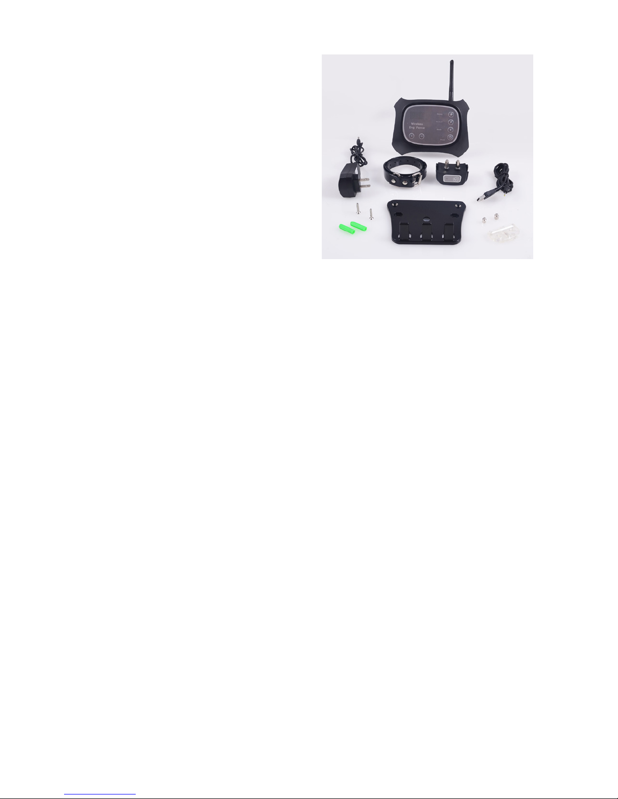
WHAT’S IN THE BOX?
• Wi-Fi Dog Fence Transmitter
• Dog Collar Receiver
• 2 Power Adapters
• Dog Collar
• Extended Metal Contact Points
• LED Test Light / Contact Point Tool
• Transmitter Wall Mounting Plate
• Two Phillips Head Screws
• Two Screw Wall Anchors
ADDITIONAL ITEMS YOU MAY NEED
• Phillips Screwdriver
• Extension cord (Use the correct extension cord gauge for the
needed length)
• Spirit Level
• Power drill
• Leash
KEY TERMS & DEFINITIONS
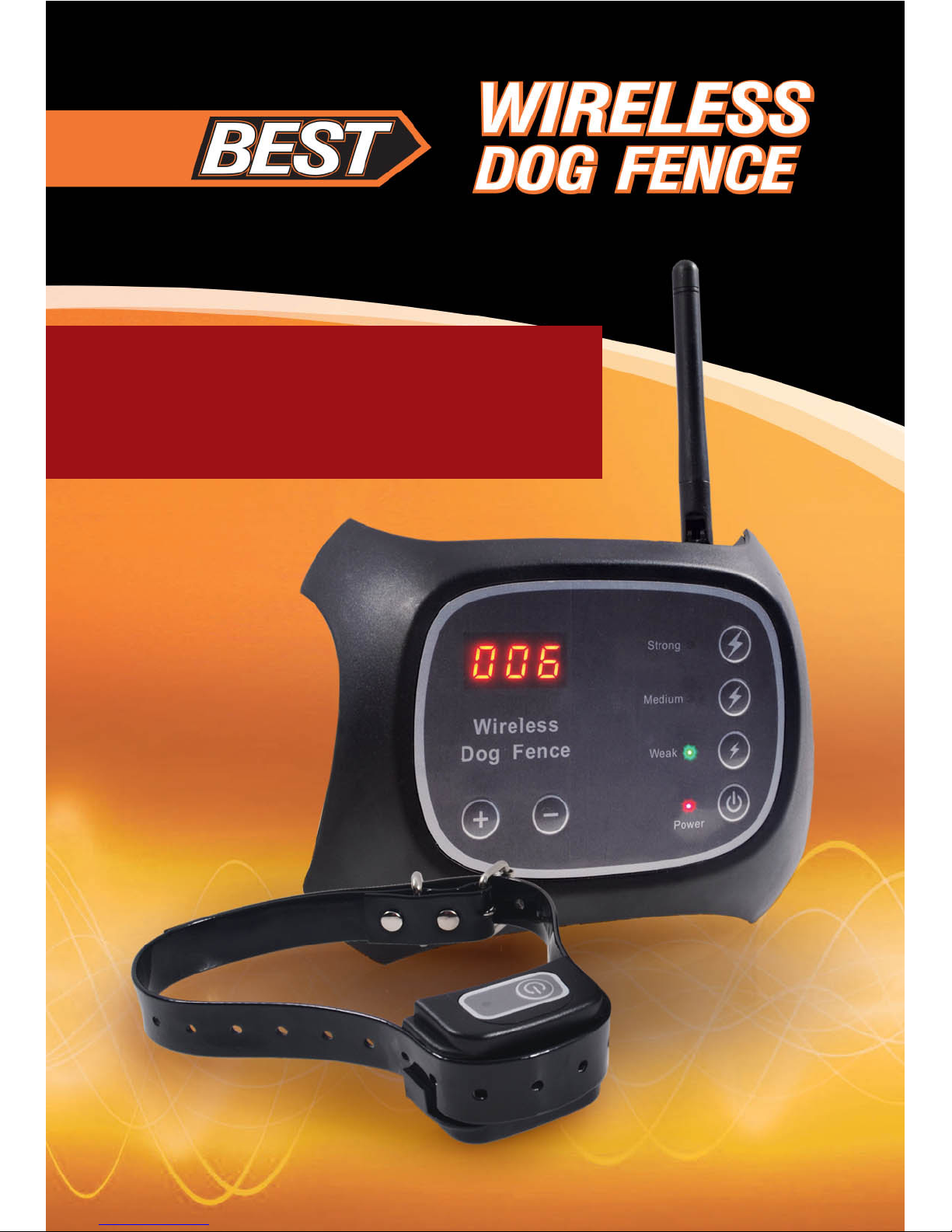
Wi-Fi Fence Transmitter - This is the black box labeled “Wireless Dog
Fence” which emits a Wireless Boundary Signal and is used to adjust the
Static Correction Boundary Radius and the Static Correction Strength.
Wireless Boundary Signal - The signal emitted from the Wi-Fi
Fence Transmitter which communicates with the Pet Collar Receiver
to initiate Warning Vibrations and Static Corrections as necessary.
This signal creates a circular boundary.
Pet Collar Receiver - The small black device attached to the pet
collar. This piece of equipment is responsible for emitting Warning
Vibrations or Static Corrections when your pet reaches the Static
Correction Boundary.
Page 3

Static Correction Boundary – This boundary is set by the user and
surrounds the edge of the Secure Pet Zone. When the Pet Collar
Receiver reaches this boundary a Warning Vibration and/or Static
Correction will be administered to encourage your pet to return to
the Secure Pet Zone.
Secure Pet Zone – The area inside the Static Correction Boundary
where your pet can roam safely.
Warning Vibration – As the Pet Collar Receiver reaches the Static
Correction Boundary it will rst emit a Warning Vibration to encourage your pet to return to the Secure Pet Zone.
Static Correction – If the pet reaches the Static Correction
Boundary and does not return to the Secure Pet Zone following the
Warning Vibration, a safe but rm electric current is passed from
the Pet Collar Receiver to the pet to encourage them to return to
the Secure Pet Zone. The Static Correction has three settings: Weak,
Medium, and Strong.
Static Correction Boundary Radius – The Static Correction Boundary is measured by the radius of the circular boundary it creates.
The Static Correction Boundary Radius is measured in meters (1
meter = approx. 3.3 feet).
Static Correction Boundary Display – The Static Correction
Boundary Radius size is indicated by an LED display in the upper left
corner of the Wi-Fi Fence Transmitter. At Level 001 the Static Correction Boundary Radius is 5 meters (approx. 16ft.). As the numerical value increases each value represents an additional 1.5 meters (approx.
6.6 feet) or Static Correction Boundary Radius distance.
Static Correction Boundary Controls – Below the Static Correction Boundary Display are two buttons labeled with a plus (+) or
minus (-) symbol. These buttons are used to increase or decrease
the size of the Static Correction Boundary Radius.
Page 4

Static Correction Strength Controls: These are the top three
buttons on the right side of the Wi-Fi Fence Transmitter labeled in
descending order; Strong, Medium and Weak. These buttons are
used to set the strength of the Static Correction emitted from the
Pet Collar Receiver.
Contact Points – The two metal prongs protruding from the Pet
Collar Receiver which are responsible for delivering the static
correction to the pet. The BEST Wi-Fi Dog Fence includes two sets of
contact points; normal and extended length.
Transmitter Wall Mounting Plate – The at black plate used to
mount the Wi-Fi Fence Transmitter to the wall and can be used to
hold Pet Collar Receivers for storage and charging.
SYSTEM OVERVIEW
The Best Wi-Fi Dog Fence is a wireless dog fence system designed
to keep your pet safely within a boundary you set. This system
emits a Wi-Fi signal to create a circular boundary; inside this boundary is considered the Secure Pet Zone where your pet can happily
and safely roam.
This product is designed to work in coordination with training.
Proper training is essential to help teach your pet where they are
allowed to be and where the Static Correction Boundary lies.
When your pet reaches the Static Correction Boundary, the Pet Collar Receiver will initiate two dierent cycles of Warning Vibrations
and Static Correction. The Warning Vibrations or Static Corrections
will cease at any time when your pet returns to the Secure Pet Zone.
If your pet remains beyond the Static Correction Boundary after
the two cycles complete, the Pet Collar Receiver will stop emitting
Warning Vibrations or Static Corrections to prevent potential harm.
Page 5
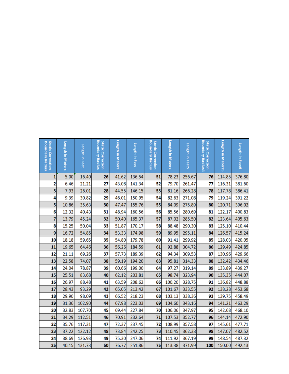
STATIC CORRECTION BOUNDARY RADIUS GUIDE
As the Static Correction Boundary is a circular boundary, the best
way to measure this boundary is using its radius (the distance from
the center of the Secure Pet Zone to the Static Correction Boundary). The Static Correction Boundary Radius is the measurement
displayed on the Static Correction Boundary Display in the upper
left corner of the Wi-Fi Fence Transmitter.
The Static Correction Boundary Radius starts at Level 001 which is a 5
meter radius (approx. 16 ft.), and increases approximately 1.5 meters
(5 ft.) with each additional setting. Below is a table to use as a guide to
determine the best Static Correction Boundary Radius for your needs.
Page 6

SYSTEM INSTALLATION
Correctly installing the BEST Wi-Fi Dog Fence is essential to proper
operation of this system. Please be aware objects can obstruct the
Wireless Boundary Signal which can decrease signal strength/distance and potentially create signal blind spots. Avoid installing the
Wi-Fi Fence Transmitter within 3 feet of large metal object such as
refrigerators or metal cabinets. Thick walls such as block or concrete
walls can also decrease the signal strength and you may need to increase the signal strength beyond the suggested setting to achieve
the desired boundary size.
When installing the BEST Wi-Fi Dog Fence be sure to select a dry,
well ventilated location, clear of any potential signal obstructions,
and preferably near a power outlet. It is important to mount the WiFi Fence Transmitter at least 60 inches o the ground (5 ft) to ensure
the transmitter antenna will achieve optimum range.
SELECTING TRANSMITTER INSTALLATION LOCATION
Selecting the installation location for the Wi-Fi Fence transmitter is
an important step. The location of the Wi-Fi Fence Transmitter will
aect which areas of your yard will fall within the Secure Pet Zone
and where the Static Correction Boundary will be located. The Wi-Fi
Fence transmitter must be located in the center of the area you are
attempting to create a boundary around.
On the next page you’ll nd several diagrams indicating the general location where the Wi-Fi Fence Transmitter should be installed to achieve
the desired Static Correction Boundary Location.
Page 7

Left Orientation Boundary
To create a Static Correction Boundary
around the left side of your property, preventing pet access to the right side of your
yard, install the Wi-Fi Fence transmitter in
the left side of your property.
Right Orientation Boundary
To create a Static Correction Boundary
around the right side of your property,
preventing pet access to the left side of your
yard, install the Wi-Fi Fence transmitter in
the right side of your property.
Rear Orientation Boundary
To create a Static Correction Boundary
around the back of your property, preventing pet access to the front of your yard,
install the Wi-Fi Fence transmitter in the
back of your property.
Front Orientation Boundary
To create a Static Correction Boundary
around the front of your property, preventing pet access to the back side of your yard,
install the Wi-Fi Fence transmitter in the
front of your property.
Whole Orientation Boundary
To create a Static Correction Boundary
around your whole property, providing free
movement for your pet around your whole
yard, install the Wi-Fi Fence transmitter in
the center of your property.
Page 8

SYSTEM INSTALLATION
Mounting the Fence Transmitter
1. Remove the Transmitter Wall Mounting Plate and Transmitter
Mounting Hardware from the product packaging.
2. Using a pencil and a spirit level, make sure your measurements
are level and mark a 4-inch (10 cm) line on the wall in your desired
mounting location.
3. Use the screw holes located on the Transmitter Wall Mounting
Plate as a template and mark the screw locations along the 4-inch
line you have just drawn.
4. With a power drill and ¼ drill bit, drill pilot holes in to the wall at
the screw location you have just marked.
5. Insert the wall anchors into the holes you have just drilled.
6. Place the Transmitter Wall Mounting Plate on the wall and align
the screw holes with the wall anchors.
7. Secure the Transmitter Wall Mounting Plate to the wall by screwing the screws provided through the screw holes in the Transmitter
Wall Mounting Plate and into the wall anchors.
8. Mount the Wi-Fi Fence Transmitter to the mounting plate by inserting the two prongs on the upper corners of the mounting plate
into the back of the Wi-Fi Fence Transmitter.
9. Remove the Transmitter Power Adapter from the packaging.
Insert the circular connector into the top of the fence transmitter,
then plug into a wall outlet.
NOTE: If necessary, consider using an extension cord of the correct
gauge to provide power to the ideal transmitter location.
Page 9

CHARGING THE PET COLLAR RECEIVER
NOTE: It is important to charge the Pet Collar Receiver for at least 1
hour or until fully charged prior to using the system for the rst time.
WARNING: THE PET COLLAR RECEIVER SHOULD ONLY BE
CHARGED BY INSERTING INTO THE CHARGING PORT ON TOP
OF THE WIFI FENCE TRANSMITTER
1. Remove the Pet Collar Receiver and Pet Collar Receiver USB
Charging Cord from the product packaging.
2. Insert the USB Connection for the charging cord into the top of
the Wi-Fi Fence Transmitter.
The charging port on the Pet Collar Receiver is located on the back
of the device under a rubber water resistant cover.
3. Remove the rubber cover and insert the small circular connector
of the USB Charging Cord into this port to begin charging the Pet
Collar Receiver. The LED light on the front of the Pet Collar Receiver
will ash to indicate it is charging.
4. Hang the Pet Collar Receiver on the storage hooks on the front of
the Transmitter Wall Mounting Plate.
5. When the Pet Collar Receiver is fully charged, the LED light will
turn solid red.
Page 10

7. If you continue to stand beyond the Static Correction Boundary
the Pet Collar Receiver will continue to vibrate again, this time for
10 seconds, then the LED Test Light will light up for 4 additional
seconds indicating a second Static Correction is being delivered.
8. If the Pet Collar Receiver never produces a Warning Vibration or
Static Correction then return to the Wi-Fi- Fence Transmitter and
increase the Static Correction Boundary Radius and repeat steps 5
and 6.
NOTE: The distance of the Static Correction Boundary may change if
you adjust the Static Correction Boundary Radius.
9. If you have completed the Short Distance Test successfully, begin
to walk back to the Wi-Fi Fence Transmitter. The Pet Collar Receiver
should not produce Warning Vibrations or Static Corrections while
walking back to the Wi-Fi Fence Transmitter.
TROUBLESHOOTING: IF YOUR EXPERIENCE DURING THE
SHORT DISTANCE TEST IS NOT CONSISTENT WITH THE
PROCESS OUTLINED ABOVE, PLEASE SEE THE
TROUBLESHOOTING SECTION.
Page 11

PET COLLAR RECEIVER SAFETY
WARNING!
• Only use the Pet Collar Receiver when necessary. DO NOT leave
the Pet Collar Receiver on your pet for any period longer than 12
consecutive hours.
• DO NOT over-tighten the Pet Collar Receiver.
The collar should be secure but loose enough to t a nger between the Pet Collar Receiver device and your pet’s skin. Check your
pet’s skin daily for irritation.
• If you see skin irritation where the Pet Collar Receiver Contact
Points rest, discontinue use of the Wi-Fi Dog Fence system until
their skin clears. If problem persists, take your pet to a vet.
• Keep the Contact Points and the skin on your pet’s neck CLEAN.
Wash with mild soap and warm water and rinse thoroughly.
• During the rst 2 weeks of using the Wi-Fi Dog Fence system,
maintain direct supervision of your pet at all times to ensure your
pet’s safety.
• ALWAYS turn o the Pet Collar Receiver before removing if from
around your pet’s neck and before turning o the Wi-Fi-Fence
Transmitter.
A LOSS OF POWER TO THE TRANSMITTER WILL INITIATE THE
STATIC CORRECTION CYCLE.
Please follow the guidelines outlined above carefully as misuse
of the Pet Collar Receiver can result in a deteriorating skin
condition known as Pressure Necrosis. This is a skin condition
resulting from excessive pressure or contact with the metallic
Pet Collar Receiver Contact Points.
Page 12

PET TRAINING
It is vital to train your pet to recognize the Static Correction Boundary
you have set so they understand where they can and cannot go.
Working with your pet to help them understand the boundaries you
have set will ensure the success of the BEST Wi-Fi Dog Fence system.
• For safety, DO NOT connect a leash to the Pet Collar Receiver as
this can lead to injury. When training your pet with a leash, be
sure to attach the leash to a secondary collar worn below the Pet
Collar Receiver so it cannot lead to any additional pressure on
the Contact Points.
• Remember when training to HAVE FUN! This is a time for you and
your pet to bond and pets respond better to positive reinforcement.
• Short, frequent training sessions are better than fewer, longer
training sessions.
RECOMMENDATION: During the rst week of training sessions, it is
suggested you use visual markers such as small ags or rope to provide
your pet with a visual reference for where the Static Correction Boundary is located.
Visual markers are not included in the BEST Wi-Fi Dog Fence package but are highly recommended for training purposes and can be
purchased online.
1. Turn on the Wi-Fi Fence Transmitter and select the desired
Static Correction Boundary Radius and Static Correction Strength.
2. Turn on the Pet Collar Receiver and t it comfortably and
securely around your pet’s neck.
3. Fit a second collar below the Pet Collar Receiver around your
pet’s neck and attach a leash.
Page 13

4. Walk with your pet around the Secure Pet Zone and begin to
approach the Static Correction Boundary.
5. Do not lead your pet over the Static Correction Boundary but
stop short and allow your pet to roam freely. When your pet
crosses the boundary and initiates the Warning Vibrations/ Static
Correction cycle help them back into the Secure Pet Zone and
praise them for returning.
6. Repeat steps 4 and 5 at multiple locations around the Static
Correction boundary you have set to help them learn the limits
of the Secure Pet Zone.
7. When your pet shows signs that they are tired or the training is
no longer providing additional benet, end the training session.
Always end training sessions with praise! You want your pet to be
happy and excited to learn.
Repeat this training exercise over the course of 2 weeks removing
the visual markers gradually to help your dog learn where the Static
Correction Boundary is without the assistance of visual aid. Also
add distraction such as toys, humans, or other pets located beyond
the Static Correction Boundary into the training program.
When your dog has learned not to cross the Static Correction
Boundary even when distractions are present you can feel condent they have learned to respect the boundary you have set.
Page 14

TROUBLESHOOTING
Pet Collar Receiver is not working.
Check the battery is charged by connecting the Pet Collar Receiver
to the Wi-Fi Fence Transmitter using Pet Collar Receiver USB
Charging Cord. A ashing red LED light on the Pet Collar Receiver
indicates the unit is still charging.
My dog does not react to any Static Correction Strength setting.
Check the the Pet Collar Receiver and ensure the Contact Points
are making direct contact with the skin on the underside of your
pet’s neck.
Consider replacing the normal length Contact Points on the Pet
Collar Receiver with the Extended Contact Points included in the
product packaging. This may provide better contact with your pet’s
skin resulting in more eective Static Correction. Consider trimming
excess fur around the Contact Points to ensure direct skin contact.
My pet is receiving a Static Correction inside the house.
Check your Static Correction Boundary Radius setting and consider
increasing the radius. The Wi-Fi Boundary signal may not be strong
enough at the current setting to penetrate all of the walls in your
home resulting in incorrect Static Correction.
Check the Power on the Wi-Fi Fence Transmitter. If the power to
the transmitter is not consistent and the transmitter goes on and
o intermittently, the Pet Collar Receiver will produce Warning
Vibrations and Static Corrections whenever the Wi-Fi Fence Transmitter loses power.
The Pet Collar Receiver turned o and won’t turn back on.
The Pet Collar Receiver is likely out of battery. Attach the Pet Collar Receiver to the Wi-Fi Fence Transmitter using the Pet Collar Receiver USB
Charging Cord and allow the Pet Collar Receiver to charge. A ashing
red LED light on the Pet Collar Receiver indicates the unit is charging,
when the collar is fully charged the LED light will turn solid red.
Page 15

TROUBLESHOOTING
My pet traveled beyond the Static Correction Boundary.
Complete a full 360-degree test of your Static Correction Boundary.
Using a fully charged Pet Collar Receiver, walk around your boundary to test for blind spots caused by Wireless Signal Interference.
Wireless signal can be caused by large metal objects, thick block
walls or electrical interference from power lines.
Consider increasing the Static Correction Strength you use for
your pet. Your pet may be receiving a Static Correction but not be
responding to the Static Correction because it is too low.
Check that the Pet Collar Receiver is properly tted. If the Pet Collar
Receiver is not properly tted, your pet may not be receiving the
Static Correction.
Consider completing an additional week of training with your pet.
Remember short, frequent training sessions are more valuable
to your pet and will be more benecial than fewer sessions of
greater length.
Page 16

SAFETY INFORMATION
WARNING
• The BEST Wi-Fi Dog Fence is NOT designed to be used with aggressive pets. Aggressive pets are more likely to negatively react in all
types of situations which may put the pet owner and others at risk
of personal injury.
• If you believe your pet could be potentially dangerous to itself or
others then please do not rely solely on the BEST Wi-Fi Dog Fence
system as a barrier.
• For safety reasons the Wi-Fi- Fence Transmitter must be installed in
a dry, well ventilated area. Moisture and electronics are a dangerous
combination and failure to mount the Wi-Fi Transmitter in a dry location can result in the system becoming inoperable and could result in
electric shock, electric sparks leading to re and possibly death.
• The Static Correction produced by this product can be dangerous
for small animals and SHOULD NOT be used on pets weighing less
than 8 pounds.
• The BEST Wi-Fi Dog Fence system SHOULD NOT be used on
humans, for any reason, ever. Using this system on another human
may result in serious injury or death.
Please be aware the BEST Wi-Fi Dog Fence system is not a physical
barrier and as such cannot prevent an animal from traveling beyond
the boundaries you have set. This system is designed to work with
training and to encourage your pet to stay within the boundaries you
have created. Not all pets are capable of being trained to work with the
BEST Wi-Fi Dog Fence system and we do not guarantee the BEST Wi-Fi
Dog Fence system will be able to contain all pets.
Page 17

TRAINING NOTES
________________________________________________________
________________________________________________________
________________________________________________________
________________________________________________________
________________________________________________________
________________________________________________________
________________________________________________________
________________________________________________________
________________________________________________________
________________________________________________________
________________________________________________________
________________________________________________________
________________________________________________________
________________________________________________________
________________________________________________________
________________________________________________________
________________________________________________________
________________________________________________________
________________________________________________________
________________________________________________________
________________________________________________________
________________________________________________________
________________________________________________________
________________________________________________________
________________________________________________________
________________________________________________________
________________________________________________________
Page 18

________________________________________________________
________________________________________________________
________________________________________________________
________________________________________________________
________________________________________________________
________________________________________________________
________________________________________________________
________________________________________________________
________________________________________________________
________________________________________________________
________________________________________________________
________________________________________________________
________________________________________________________
________________________________________________________
________________________________________________________
________________________________________________________
________________________________________________________
________________________________________________________
________________________________________________________
________________________________________________________
________________________________________________________
________________________________________________________
________________________________________________________
________________________________________________________
________________________________________________________
________________________________________________________
________________________________________________________
________________________________________________________
Page 19

Page 20

§ 15.19 Labeling requirements.
This device complies with part 15 of the FCC Rules. Operation is subject to the
following two conditions: (1) This device may not cause harmful interference, and (2)
this device must accept any interference received, including interference that may cause
undesired operation.
§ 15.21 Information to user.
Any Changes or modifications not expressly approved by the party responsible for
compliance could void the user's authority to operate the equipment.
§ 15.105 Information to the user.
Note: This equipment has been tested and found to comply with the limits for a Class B
digital device, pursuant to part 15 of the FCC Rules. These limits are designed to
provide reasonable protection against harmful interference in a residential installation.
This equipment generates uses and can radiate radio frequency energy and, if not
installed and used in accordance with the instructions, may cause harmful interference
to radio communications. However, there is no guarantee that interference will not
occur in a particular installation. If this equipment does cause harmful interference to
radio or television reception, which can be determined by turning the equipment off and
on, the user is encouraged to try to correct the interference by one or more of the
following measures:
-Reorient or relocate the receiving antenna.
-Increase the separation between the equipment and receiver.
-Connect the equipment into an outlet on a circuit different from that to which the
receiver is connected.
-Consult the dealer or an experienced radio/TV technician for help.
* RF warning for Portable device:
The device has been evaluated to meet general RF exposure requirement. The device
can be used in portable exposure condition without restriction.
 Loading...