

Page 1
Model WBF4I
In USA - BEST® Hartford, Wisconsin
REGISTER YOUR PRODUCT ONLINE AT : www.BestRangeHoods.com/register
For additional Information visit www.BestRangeHoods.com
Page 2
READ AND SAVE THESE INSTRUCTIONS
!
!
INTENDED FOR DOMESTIC COOKING ONLY
WARNING
TO REDUCE THE RISK OF FIRE, ELECTRIC SHOCK, OR INJURY TO PERSON(S)
OBSERVE THE FOLLOWING:
1. Use this unit only in the manner intended by the manufacturer. If you have
questions, contact the manufacturer at the address or telephone number listed
in the warranty.
2. Before servicing or cleaning unit, switch power off at service panel and lock
service disconnecting means to prevent power from being switch on accidentally.
When the service disconnecting means cannot be locked, securely fasten a
prominent warning device, such as a tag, to the service panel.
3. Installation work and electrical wiring must be done by qualified personnel
in accordance with all applicable codes and standards, including fire-rated
construction codes and standards.
4. Sufficient air is needed for proper combustion and exhausting of gases
through the flue (chimney) of fuel burning equipment to prevent backdrafting.
Follow the heating equipment manufacturer’s guidelines and safety
standards such as those published by the National Fire Protection
Association (NFPA), the American Society for Heating, Refrigeration
and Air Conditioning Engineers (ASHRAE) and the local code authorities.
5. When cutting or drilling into wall or ceiling, do not damage electrical wiring and
other hidden utilities.
6. Ducted fans must always be vented to the outdoors.
7. Do not use this unit with any other solid-state speed control device.
8. To reduce the risk of fire, use only steel ductwork.
9. This unit must be grounded.
TO REDUCE THE RISK OF A RANGE TOP GREASE FIRE:
a) Never leave surface units unattended at high settings. Boilovers cause smoking
and greasy spillovers that may ignite. Heat oils slowly on low or medium settings.
b) Always turn hood ON when cooking at high heat or when cooking flaming foods
(i.e. Crêpes Suzette, Cherries Jubilee, Peppercorn Beef Flambé).
c) Clean ventilating fans frequently. Grease should not be allowed to accumulate
on fan or filters.
d) Use proper pan size. Always use cookware appropriate for the size of the
surface element.
TO REDUCE THE RISK OF INJURY TO PERSON(S) IN THE EVENT OF A RANGE
TOP GREASE FIRE, OBSERVE THE FOLLOWING*:
1. SMOTHER FLAMES with a close-fitting lid, cookie sheet, or metal tray, then turn
off the burner. BE CAREFUL TO PREVENT BURNS. IF THE FLAMES DO NOT
GO OUT IMMEDIATELY, EVACUATE AND CALL THE FIRE DEPARTMENT.
2. NEVER PICK UP A FLAMING PAN – You may be burned.
- 2 -
Page 3

!
3. DO NOT USE WATER, including wet dishcloths or towels – This could cause
a violent steam explosion.
4. Use an extinguisher ONLY if:
A. You know you have a Class ABC extinguisher and you know how to
operate it.
B. The fire is small and contained in the area where it started.
C. The fire department has been called.
D. You can fight the fire with your back to an exit.
* Based on “Kitchen Fire Safety Tips” published by NFPA.
CAUTION
1. For indoor use only.
2. For general ventilating use only. Do not use to exhaust hazardous or explosive
materials and vapors.
3. To avoid motor bearing damage and noisy and/or unbalanced impeller, keep
drywall spray, construction dust, etc. off power unit.
4. Do not use over cooking equipment greater than 60,000 BTU/hr. as the blower
motor will shut down intermittently.
5. Your hood motor has a thermal overload which will automatically shut off the
motor if it becomes overheated. The motor will restart when it will cool down. If
the motor continues to shut off and restart, have the hood serviced.
6. The bottom of the hood MUST NOT BE LESS than 24” and at a maximum of
30” above cooktop for best capture of cooking impurities.
7. Two installers are recommended because of the size of this hood.
8. To reduce risk of fire and to properly exhaust air, be sure to duct air outside. Do
not exhaust air into spaces within walls or ceilings or into attics, crawl spaces,
or garages.
9. Be careful when installing the decorative flue and hood, they may have sharp
edges.
10. Please read specification label on product for further information and
requirements.
- 3 -
Page 4
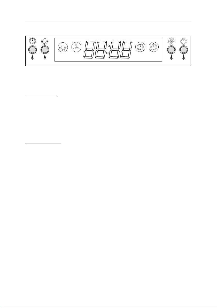
OPERATION
The hood is operated using the push buttons on the front panel.
Speed
Lamp
2 3 4
1
TIME/DELAY (2 Functions)
TIME SETTING
This button is used to set time when lighting and blower are not in use. Time is
displayed in a 12-hour cycle. To set time, press the push button (1) for 3 seconds.
The first two digits will flash. Use the blower push button (3) to increase, and the
lighting pushbutton (2) to decrease. Press the time/delay push button (1) again. The
last two digits will flash. Use the blower push button (3) to increase and the lighting
push button (2) to decrease. Press the time/delay button (1) again to confirm and
exit time setting mode.
DELAY SETTING
When blower is in use, this button is used as the delay off setting button. To set
delay, press the push button (1). The delay is factory set at 5 minutes, but can be
set from 1 up to 60 minutes. Use blower push button (3) to increase, and lighting
push button (2) to decrease. Countdown will be displayed on the LCD screen,
blower symbol will be activated, and the button (1) backlight will flash. Blower
will continue to operate for the programmed time and then will stop automatically
(delay-off setting does not affect lighting as it works independently). To cancel
delay function, press time/delay push button (1) again. The blower will continue
to operate and won’t stop until ON/OFF push button (4) is pressed. To turn delay
function and blower OFF at once, press ON/OFF push button (4). NOTE: Delay will
be reset if blower speed is modified during delay setting mode.
Timer
Power
nottub hsup rewolB )3nottub hsup yaleD/emiT )1
nottub hsup FFO/NO )4nottub hsup gnithgiL )2
LIGHTING
Press the lighting push button (2) once to turn the LCD screen on. To turn the
lights on, press the lighting push button (2) once more. Press it again to turn the
lights OFF. The LCD screen will turn off automatically after 15 seconds of inactivity
(blower and/or lights).
BLOWER
The blower push button (3) turns the blower on to one of three speed settings: LOW,
MEDIUM or HIGH. Press the blower (3) or ON/OFF (4) push button once to turn
the LCD screen on. Press the blower (3) or ON/OFF (4) push button once more to
turn the blower on at the last selected speed. Blower symbol will be activated. To
change the blower speed, press the blower push button (3) until the desired speed
is obtained. Press the ON/OFF push button (4) to turn the blower OFF. The last
speed used will be memorized. NOTE: When blower is turned on, 100% of power
level is activated for 1 to 2 seconds. It will then operate at the previous setting.
- 4 -
Page 5
!
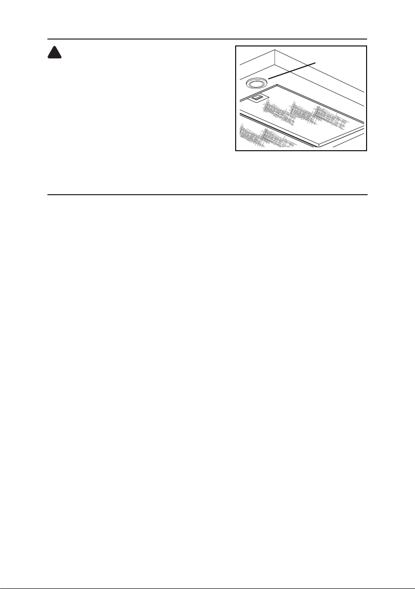
LIGHT BULBS
CAUTION
Bulbs may be hot. Always allow bulbs to
cool down before removing them.
This range hood requires two halogen bulbs
(Type JC, 12V, 20W Max, G-4 Base).
To change bulbs:
1. Remove light bulb cover by gently pushing
it upward and turning it counterclockwise.
2. Replace bulb.
3. Re-install light bulb cover by gently pushing it upward and turning it clockwise.
LIGHT BULB
COVER
CLEANING AND MAINTENANCE
Proper maintenance of the Range Hood will assure proper performance of the unit.
Motor
The motor is permanently lubricated and never needs oiling. If the motor bearings make
excessive or unusual noise, replace the motor with the exact service motor. The impeller
should also be replaced.
Grease Filter
The grease filter should be cleaned frequently. Use a warm detergent solution. Grease
filter is dishwasher safe.
Clean all-metal filters in the dishwasher using a non-phosphate detergent. Discoloration of
the filter may occur if using phosphate detergents, or as a result of local water conditions but this will not affect filter performance. This discoloration is not covered by the warranty.
See “INSTALL FILTERS” section for removal and installation instructions.
Non-ducted Recirculation Filter
The non-ducted recirculation filter should be changed every 6 months. Replace more
often if your cooking style generates extra grease, such as frying and wok cooking. See
“INSTALL FILTERS” section for removal and installation instructions.
Stainless Steel Cleaning
DO:
• Regularly wash with clean cloth or rag
soaked with warm water and mild soap
or liquid dish detergent.
• Always clean in the direction of original
polish lines.
• Always rinse well with clear water (2 or
3 times) after cleaning. Wipe dry completely.
• You may also use a specialized household stainless steel cleaner.
DON’T:
• Use any steel or stainless steel wool or
any other scrapers to remove stubborn
dirt.
• Use any harsh or abrasive cleansers.
• Allow dirt to accumulate.
• Let plaster dust or any other construction residues reach the hood. During
construction/renovation, cover the range
hood to make sure no dust sticks to the
stainless steel surface.
Avoid: When choosing a detergent
• Any cleaners that contain bleach will attack stainless steel
• Any products containing: chloride, fluoride, iodide, bromide will deteriorate surfaces rapidly.
• Any combustible products used for cleaning such as acetone, alcohol, ether, benzol, etc.,
are highly explosive and should never be used close to a range.
- 5 -
Page 6
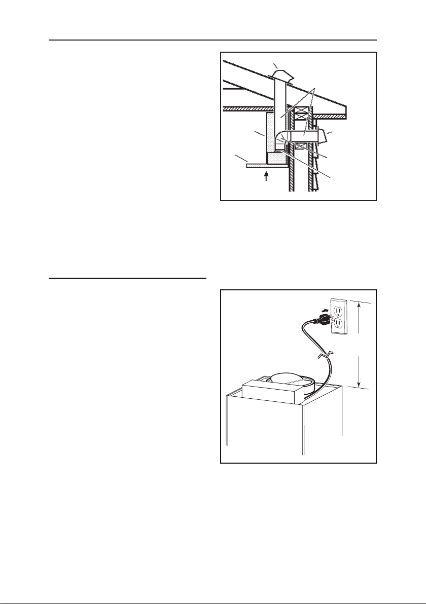
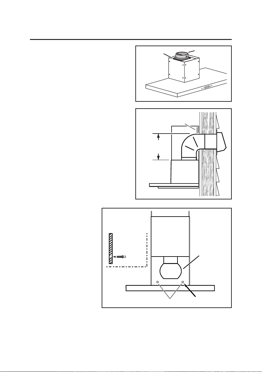
INSTALL THE DUCTWORK (Ducted Hoods Only)
NOTE: To reduce the risk of fire, use
only metal ductwork.
1. Decide where the ductwork will run
ROOF CAP
6” ROUND
DUCT
between the hood and the outside.
2. A straight, short duct run will allow
the hood to perform most efficiently.
3. Long duct runs, elbows, and
transitions will reduce the
performance of the hood. Use as
few of them as possible. Larger
ducting may be required for best
performance with longer duct runs.
DECORATIVE
FLUE
HOOD
24” TO 30” ABOVE
COOKING SURFACE
WALL
CAP
6” ROUND
ELBOW
DAMPER /
DUCT
CONNECTOR
4. Install a roof or wall cap. Connect
round metal ductwork to cap and work back towards hood location. Use duct
tape to seal the joints between ductwork sections.
INSTALL THE WIRING
1. GROUNDING INSTRUCTIONS
This appliance must be grounded.
In the event of an electrical short
circuit, grounding reduces the risk
of electric shock by providing an
escape wire for the electric current.
This appliance is equipped with a
cord having a grounding wire with
a grounding plug. The plug must
be plugged into an outlet that is
properly installed and grounded.
11½”
MAX.
2. Position the electrical outlet
within the space covered by the
decorative flue and where it will not
interfere with the round duct. Make
sure the outlet is no further than
11½” from where the cord exits from the hood and that the outlet does not
interfere with a mounting bracket fastening area or where the decorative flue
touches the wall.
- 6 -
Page 7
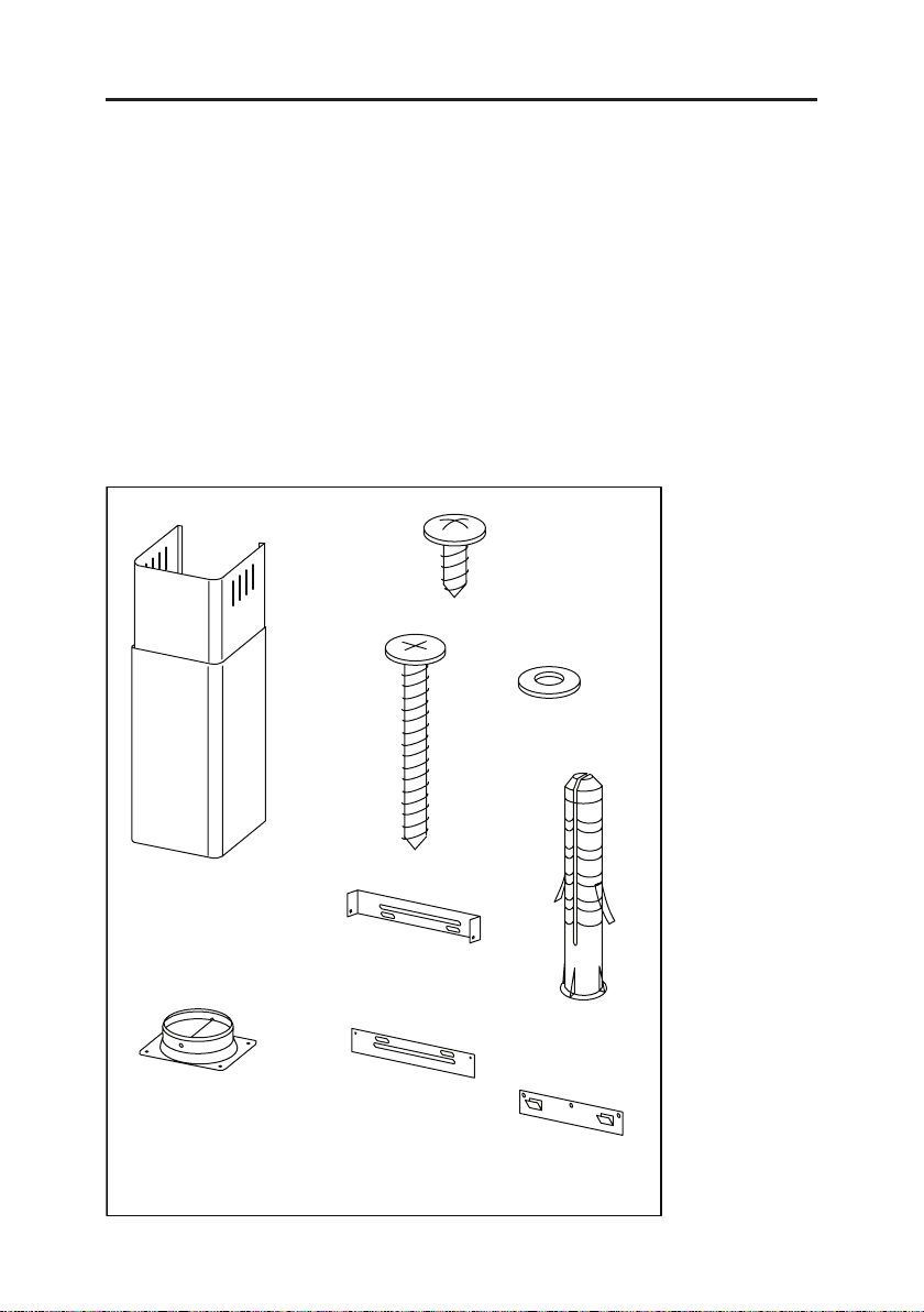
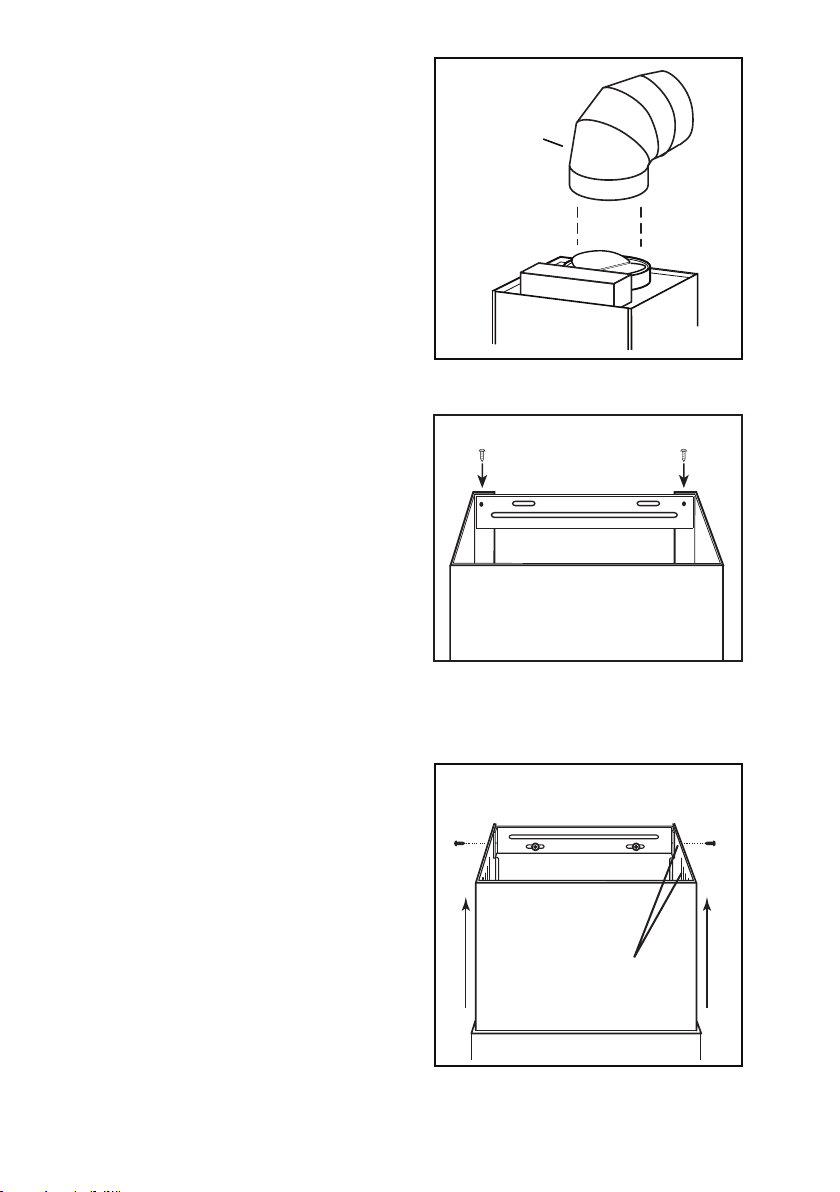
PREPARE THE HOOD
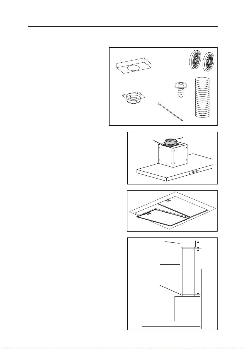
Unpack hood and check contents. You should receive:
1 - Hood
1 - Decorative Flue Assembly
1 - Damper / Duct Connector
1 - Lower Flue Mounting Bracket
1 - Upper Flue Mounting Bracket
1 - Hood Mounting Bracket
2 - Aluminum Grease Filters (installed in hood) (3 filters - 36” hood only)
1 - Parts Bag containing:
8 - Mounting Screws (#8 x 3/8” Pan Head)
7 - Mounting Screws (#8 x 1-1/2” Flat Head)
7 - Drywall Anchors
2 - Washers
1 - Installation Manual
8 MOUNTING
SCREWS (#8 x
3/8” Pan Head)
7 MOUNTING
SCREWS
(#8 X 1-1/2”
Flat Head)
2 WASHERS
DECORATIVE FLUE
DAMPER / DUCT
CONNECTOR
UPPER
FLUE MOUNTING
BRACKET
LOWER
FLUE MOUNTING
BRACKET
7 DRYWALL
ANCHORS
HOOD
MOUNTING
BRACKET
- 7 -
Page 8
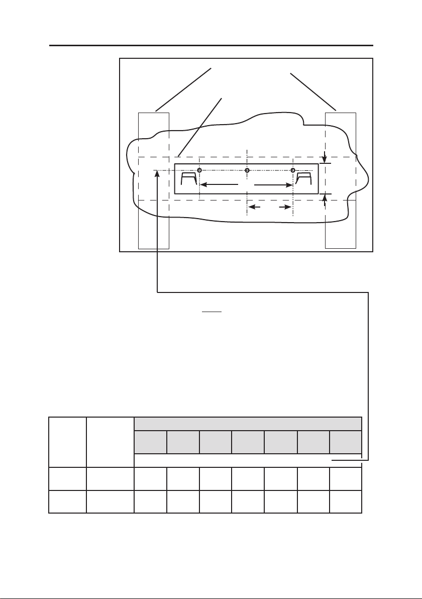
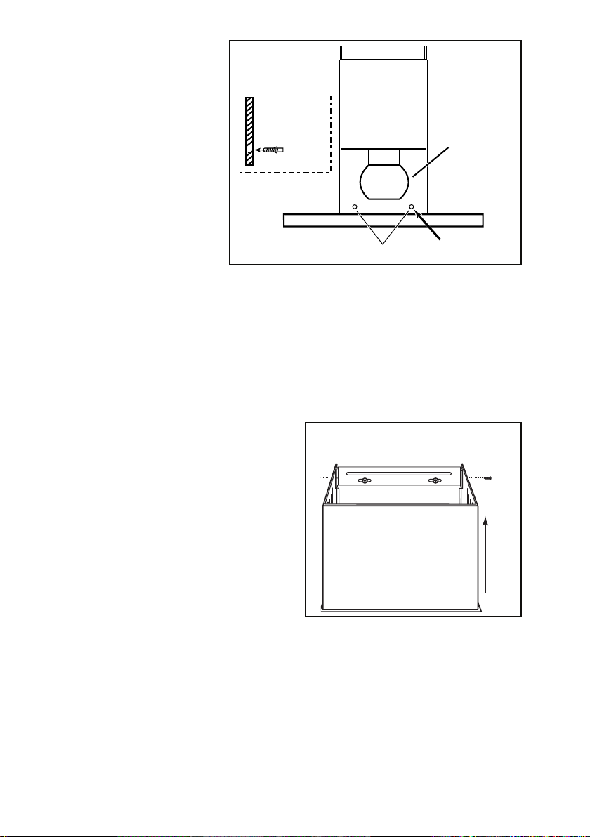
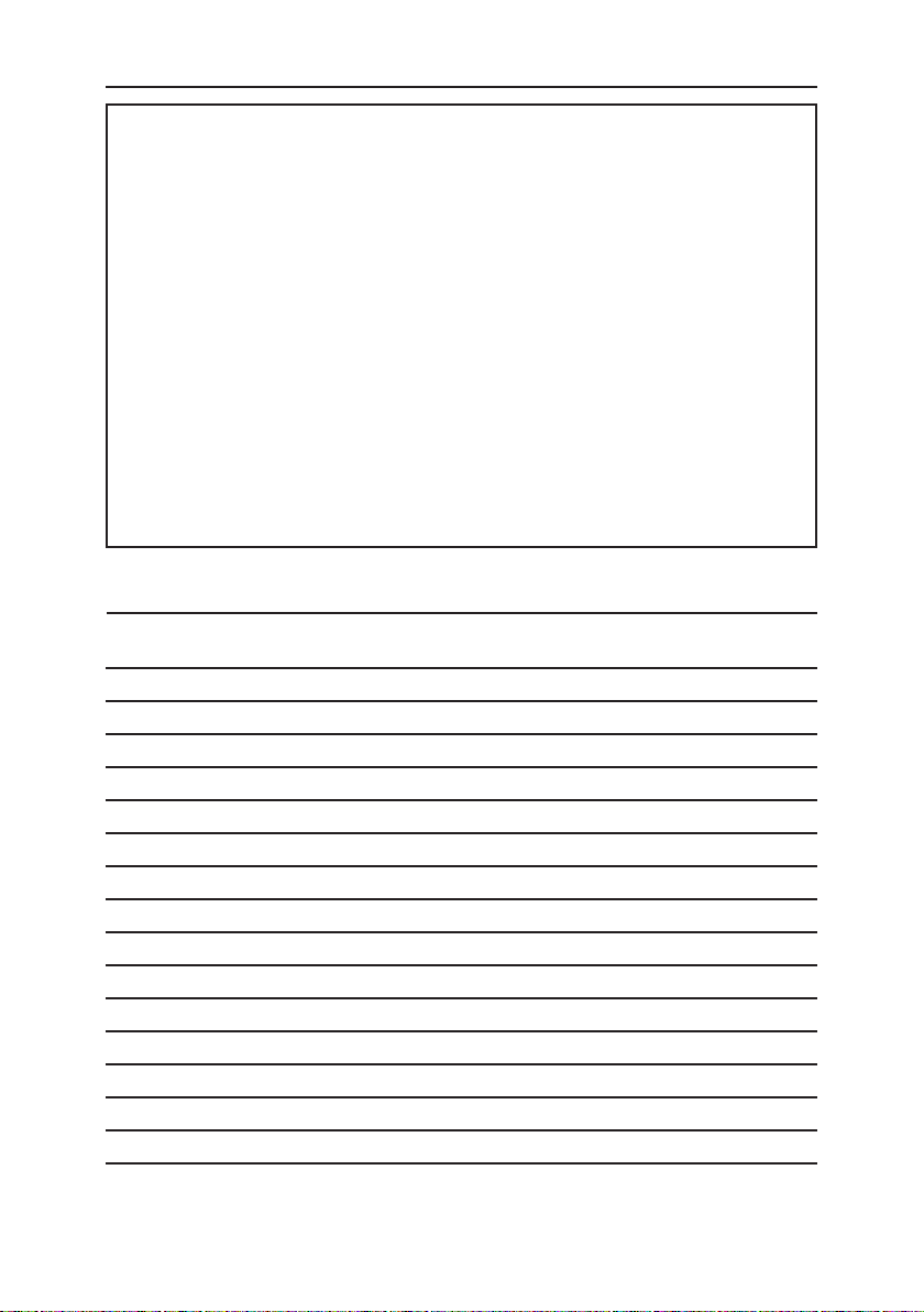
INSTALL THE HOOD MOUNTING BRACKET
WALL STUDS
FRAMING BEHIND
DRYWALL
C
L
9”
19⁄16”
41⁄2”
35-7/8” = bottom of hood 24” above cooktop
41-7/8” = bottom of hood 30” above cooktop
1. Construct wood wall framing that is flush with interior surface of wall studs.
Make sure:
a) the framing is centered over installation location.
b) the height of the framing will allow the mounting bracket to be secured to
the framing within the dimensions shown.
2. After wall surface is finished, carefully center and level the hood mounting
bracket and secure it to wall framing with (3) #8 x 1-1/2” mounting screws.
Tighten the screws completely.
HOOD DISTANCE ABOVE 36” HIGH COOK TOP (see note a.)
CEILING
HEIGHT
7-FT. 8-IN.
MINIMUM
8 OR 9
FEET
DUCT
METHOD
DUCTED OR
NON-DUCTED
DUCTED OR
NON-DUCTED
24”
35-7/8” 36-7/8” 37-7/8” 38-7/8”
35-7/8” 36-7/8” 37-7/8” 38-7/8” 39-7/8” 40-7/8” 41-7/8”
25”
MOUNTING BRACKET LOCATION ABOVE 36” COOK TOP
26”
27”
28”
29”
30”
Note:
a. Minimum hood distance above cook top must not be less than 24”.
A maximum of 30” above cook top is highly recommended for best capture of cooking impurities.
Distances over 30” are at the installer’s and user’s discretion; and if ceiling height and flue length
permit.
- 8 -
Page 9
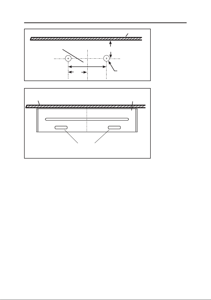
INSTALL UPPER FLUE MOUNTING BRACKET
Center of installation
Recommended
distance between
screw holes
Ceiling
Upper flue mounting
1. Drill two 5⁄16” diameter holes where shown. Insert drywall an-
chors into the holes.
2. Center the bracket over the hood location and flush with the
ceiling. Make sure that the slots of the upper flue bracket are
at the bottom. Secure the upper flue bracket to the wall using (2)
#8 x 1½” mounting screws.
3. Tighten the screws completely. Make sure that the bracket is
tight against the wall.
C
L
7½”
3¾”
Center of
installation
C
L
bracket slots
Ceiling
11⁄8”
Ø 5/16” TYP.
Flush with
the ceiling
- 9 -
Page 10
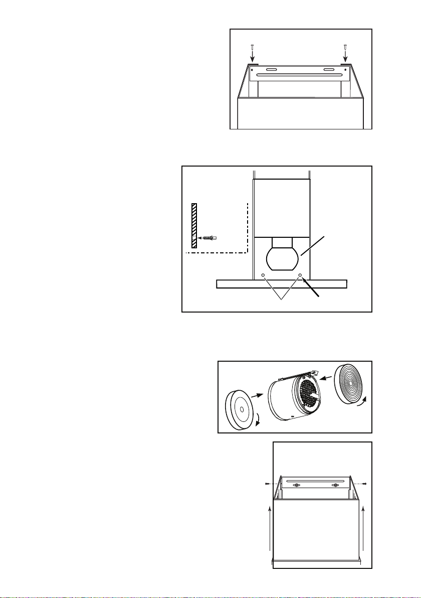
INSTALL THE HOOD
(Horizontally Ducted Hoods Only)
1. DO NOT REMOVE the protective
plastic film covering the decorative
flue and the hood at this time.
2. Lay the back side of the hood
(4) #8 X 3/8”
PAN HEAD
SHEET METAL
SCREWS
DAMPER / DUCT
CONNECTOR
flat on a table. Use a piece of
cardboard to avoid damaging the
table or the hood.
3. Attach damper / duct connector to
top of hood using (4) #8 x 3/8” Pan
Head mounting screws.
4. Remove the grease filters by
pushing down the metal latch
tab and tilting filters downward to
LOWER FLUE
MOUNTING BRACKET
remove.
5. Carefully rotate hood upright.
6. Make sure there will be adequate
clearance between top of hood
and lower flue mounting bracket
11½”
MAX.
for ductwork. Elbow must be
located below lower flue mounting
bracket.
7. Align the hood and center it above
the hood mounting bracket. Gently
lower the hood until it securely
engages the bracket.
8. With the hood hanging
in place, drill through
the both holes located
in the inside lower
back of hood using a
5/16” drill bit. Insert
the included drywall
anchors into the
drilled holes (one for
each hole). Install (2)
washers and (2) no. 8
SIDE VIEW
INSIDE BACK
OF
THE HOOD
OTOR/BLOWER
M
ASSEMBLY
x 1½” mounting screws
through the back of
the hood and into
the drywall anchors.
Verify that the hood is
centered and leveled.
Tighten all screws
HOLES LOCATION
Ø5/16” TYP.
completely.
9. Reinstall grease filters by aligning rear filter tabs with slots in the hood. push
down the metal latch tab, push filter into position and release. Make sure
filters are securely engaged after installation.
- 10 -
Page 11
10. Measure and install 6” round metal
6”
ductwork to roof cap or wall cap
and 900 elbow over duct collar on
hood. Use duct tape to make all
joints secure and air tight.
11. Plug hood power cord into the
outlet.
ROUND
ELBOW
12. Remove the upper flue from inside
the lower flue. Install the lower flue
LOWER FLUE MOUNTING BRACKET
bracket to the lower flue using (2)
flue bracket screws no. 8 x 3/8”.
Make sure that the slots are at the
top. Carefully replace the upper
flue inside the lower flue, with the
upper flue recirculation slots and
(2) bracket holes on top. Remove
protective plastic film covering the
lower flue only.
LOWER
FLUE
13. Carefully place both flues on top of
the hood.
Tabs on bottom edge of lower flue
fit into slots on top of hood.
14. Slide the upper flue upward until
it is aligned with its upper flue
mounting bracket. The bracket
UPPER FLUE MOUNTING BRACKET
FRONT VIEW
should be inside the flue. Secure
the upper flue to the upper flue
mounting bracket using (2) no. 8 x
3/8” mounting screws.
UPPER FLUE
15. Remove protective plastic film
covering the upper flue and the
hood.
RECIRCULATION
SLOTS &
BRACKET HOLES
- 11 -
Page 12
INSTALL THE HOOD
(Vertically Ducted Hoods Only)
1. DO NOT REMOVE the protective
plastic film covering the decorative
flue and the hood at this time.
2. Lay the back side of the hood
(4) #8 X 3/8”
PAN HEAD
SHEET METAL
SCREWS
DAMPER / DUCT
CONNECTOR
flat on a table. Use a piece of
cardboard to avoid damaging the
table or the hood.
3. Attach damper / duct connector to
top of hood using (4) #8 x 3/8” Pan
Head mounting screws.
4. Remove the grease filters by pushing down the metal latch tab and tilting
filters downward to remove.
5. Carefully rotate hood upright.
6. Remove the upper flue from inside
the lower flue. Install the lower
LOWER FLUE MOUNTING BRACKET
flue bracket to the lower flue using
(2) flue bracket screws #8 x 3/8”,
make sure that the slots are at the
top. Carefully replace the upper
flue inside the lower flue, with the
upper flue recirculation slots and
(2) bracket holes on top. Remove
protective plastic film covering the
lower flue only.
LOWER
FLUE
7. Carefully place both flues on top of
hood.
Tabs on bottom edge of lower flue
fit into slots on top of hood.
8. Measure and install
metal ductwork to hood
duct connector. Use duct
tape to make all joints
6” ROUND
STEEL DUCT
DUCT LENGTH
secure and air tight.
9. Hold hood up close to
wall mounting location
DECORATIVE
FLUE
and plug power cord into
wall outlet.
10. Align the hood and
center it above the
hood mounting bracket. Make sure ductwork on hood lines up and attaches
to ductwork in ceiling. Gently lower the hood until it securely engages the
bracket.
11. Use duct tape to make all joints secure and air tight.
- 12 -
Page 13
12. With the hood hanging
in place, drill through
both holes located
in the inside lower
back of hood using
a 5⁄16” drill bit. Insert
the included drywall
anchors into the
drilled holes (one for
SIDE VIEW
INSIDE BACK
OF
THE HOOD
OTOR/BLOWER
M
ASSEMBLY
each hole). Install (2)
washers and (2) #8
x 1-1/2” mounting
screws through the
hood back and into
the drywall anchors.
HOLES LOCATION
Ø5/16” TYP.
Verify that the hood is
centered and leveled. Tighten all screws completely.
13. Reinstall grease filters by aligning rear filter tabs with slots in the hood.
Pushdown the metal latch tab, push filter into position and release. Make
sure filters are securely engaged after installation.
14. Slightly push aside the upper flue to avoid any damage while installing the
lower flue to the hood top using (2) #8 x 3/8” screws through the lower flue
side slots.
15. Slide the upper flue upward until it
is aligned with its mounting
bracket. The bracket should be
inside the flue. Secure the upper
flue to the upper flue mounting
bracket using (2)
#8 x 3/8” mounting screws.
16. Remove protective plastic film
covering the upper flue and the
hood.
UPPER FLUE MOUNTING BRACKET
FRONT VIEW
UPPER
FLUE
- 13 -
Page 14
INSTALL THE HOOD
(Non-Ducted Hoods Only)
NOTE: Non-ducted installations
require Non-Duct Kit, Model
ANKWBF4 (purchase
separately).
1. CAUTION: Do not use plastic
or rigid metal duct.
2. Do not remove the protective
plastic film covering the
decorative flue and the hood at
this time.
3. Lay the back side of the hood
flat on a table. Use a piece of
cardboard to avoid damaging
the table or the hood.
NOTE: Non-ducted installations
require Non-Duct Kit, Model ANKWBF4
(purchase separately).
1. CAUTION: Do not use plastic or rigid
metal duct.
2. Do not remove the protective plastic
film covering the decorative flue and
the hood at this time.
3. Lay the back side of the hood
flat on a table. Use a piece of
cardboard to avoid damaging the
table or the hood.
4. Attach damper / duct connector to
top of hood using (4) #8 x 3/8” Pan
Head mounting screws.
5. Remove damper flaps from
damper / duct connector and
discard flaps.
6. Remove the grease filters
by pushing down the metal
latch tab and tilting filters
downward.
7. Attach non-duct collar to non-
duct plenum using (4) #8 x
3/8” Pan Head screws.
8. Measure distance “A”. This will
be the length of the extended
flex duct.
9. Attach aluminum flexible duct
to the damper / duct connector
with a tie wrap.
10. Attach flexible duct to non-duct
plenum collar and secure with
tie wrap. Tape all joints with
duct tape.
NON-DUCT KIT
MODEL ANKWBF4 CONTENTS
NON-DUCTED
RECIRCULATION
FILTERS
NON-DUCT
PLENUM
NON-DUCT PLENUM
COLLAR
(4) #8 X 3/8”
PAN HEAD
SHEET METAL
SCREWS
NON-DUCT PLENUM
6” ALUMINUM
DAMPER / DUCT
CONNECTOR
- 14 -
FLEX DUCT
8 MOUNTING
SCREWS
(#8 x 3/8”
PanHead)
2 TIE
WRAPS
FLEXIBLE DUCT
DAMPER / DUCT
CONNECTOR
4-7/8”
A
Page 15
11. Remove the upper flue from inside the
lower flue. Install the lower flue bracket to
LOWER FLUE MOUNTING BRACKET
the lower flue using (2) flue bracket screws
#8 x 3/8”. Make sure that the slots are at
the top. Carefully replace the upper flue
inside the lower flue, with the upper flue
recirculation slots and (2) bracket holes on
top. Remove protective plastic film covering
the lower flue only.
12. Carefully place both flues on top of hood.
LOWER
FLUE
Tabs on bottom edge of lower flue fit into slots on top of hood.
13. Attach non-duct plenum with collar to upper flue using (4) #8 x 3/8” Pan Head screws.
14. Hold hood up close to wall
mounting location and plug
power cord into wall outlet.
15. Align the hood and center
it above the hood mounting
bracket. Gently lower
the hood until it securely
engages the bracket.
SIDE VIEW
INSIDE BACK
OF
THE HOOD
OTOR/BLOWER
M
ASSEMBLY
16. With the hood hanging in
place, drill through both holes
located in the inside lower
back of hood using a 5⁄16”
dril bit. Insert the included
drywall anchors into the
HOLES LOCATION
Ø5/16” TYP.
drilled holes (one for each
hole). Install (2) washers and (2) #8 x 1-1/2” mounting screws through the back of
the hood and into the drywall anchors. Verify that the hood is centered and leveled.
Tighten all screws completely.
17. Attach (2) two non-duct recirculation
filters to sides of blower by aligning key
lock slot and rotating until filters lock
into place.
For replacement non-duct recirculation
filters - purchase S97018030 or
ROUNDFILTER.
18. Reinstall grease filters by aligning rear
filter tabs with slots in the hood. Push down the metal
latch tab, push filter into position and release. Make
sure filters are securely engaged after installation.
UPPER FLUE
MOUNTING BRACKET
FRONT VIEW
19. Slide up the upper flue until it is aligned with its
mounting
bracket. The bracket should be inside the flue.
Secure the upper flue on the upper flue mounting
bracket using (2) #8 x 3⁄8” mounting screws.
UPPER
FLUE
20. Remove protective plastic film covering the flue and
the hood.
- 15 -
Page 16
WARRANTY
Broan-NuTone LLC (Broan-NuTone) warrants to the original consumer purchaser of Best products that such products
will be free from defects in materials or workmanship for a period of one year from the date of original purchase. THERE
ARE NO OTHER WARRANTIES, EXPRESS OR IMPLIED, INCLUDING, BUT NOT LIMITED TO, IMPLIED WARRANTIES OR MERCHANT ABILITY OR FITNESS FOR A PARTICULAR PURPOSE.
During this one-year period, Broan-NuTone will, at its option, repair or replace, without charge, any product or part which
is found to be defective under normal use and service.
THIS WARRANTY DOES NOT EXTEND TO FLUORESCENT LAMP STARTERS, TUBES, HALOGEN AND INCANDESCENT BULBS, FUSE, FILTERS, DUCTS, ROOF CAPS, WALL CAPS AND OTHER ACCESSORIES FOR DUCTING.
This warranty does not cover (a) normal maintenance and service or (b) any products or parts which have been subject
to misuse, negligence, accident, improper maintenance or repair (other than by Broan-NuTone), faulty installation or
installation contrary to recommended installation instructions.
The duration of any implied warranty is limited to the one-year period as specified for the express warranty. Some states
do not allow limitation on how long an implied warranty lasts, so the above limitation may not apply to you.
BROAN-NUTONE’S OBLIGATION TO REPAIR OR REPLACE, AT BROAN-NUTONE’S OPTION, SHALL BE THE
PURCHASER’S SOLE AND EXCLUSIVE REMEDY UNDER THIS WARRANTY. BROAN-NUTONE SHALL NOT BE LIABLE FOR INCIDENTAL, CONSEQUENTIAL OR SPECIAL DAMAGES ARISING OUT OF OR IN CONNECTION WITH
PRODUCT USE OR PERFORMANCE. Some states do not allow the exclusion or limitation of incidental or consequential
damages, so the above limitation or exclusion may not apply to you.
This warranty gives you specific legal rights, and you may also have other rights, which vary from state to state. This
warranty supersedes all prior warranties.
To qualify for warranty service, you must (a) notify Broan-NuTone at the address stated below or telephone number stated
below, (b) give the model number and part identification and (c) describe the nature of any defect in the product or part.
At the time of requesting warranty service, you must present evidence of the original purchase date.
In USA - BEST®, 926 W. State Street, Hartford, WI 53027 (800-558-1711)
In Canada - BEST®, 550 Lemire Blvd., Drummondville, QC J2C 7W9 (866-737-7770)
www.BestRangeHoods.com
ONE YEAR LIMITED WARRANTY FOR BEST PRODUCTS
SERVICE PARTS
KEY PART NO. DESCRIPTION
1 S99528393 Decorative Upper and Lower Flues
2 S99526974 Motor / Blower Assembly
3 S99526975 Light Socket Assembly
4 S99527010 Light Trim Ring / Lens Assembly
5 S99527660 User Interface Assembly
6 S99527665 Control Board
7 S97018027 Aluminum Grease Filters (pair for 30”)
S97018028 Aluminum Grease Filters (set of 3 for 36”)
8 S97018030 Non-Duct Recirculation Filter (pair)
9 S99526983 Damper / Duct Connector
10 S99526984 6” Dia. Expandable Flexible Aluminum Duct
11 S99526985 Non-Duct Plenum Assembly
S99527012 Capacitor (not shown)
S99527011 Transformer (not shown)
S99526994 Parts Bag (not shown)
Order service parts by Part No. - not by Key No.
- 16 -
Page 17

SERVICE PARTS
11
10
9
1
Replacement parts can be
ordered on our website:
www.BestRangeHoods.com
6
8
2
3
4
5
7
- 17 -
99528392B
Page 18

Modèle WBF4I
Aux États-Unis - BEST® Hartford, Wisconsin
ENREGISTREZ VOTRE PRODUIT EN LIGNE À : www.BestRangeHoods.com/register
Pour de plus amples informations, visitez www.BestRangeHoods.com
- 18 -
Page 19

LIRE CES DIRECTIVES ET LES CONSERVER
!
!
POUR USAGE DOMESTIQUE SEULEMENT
AVERTISSEMENT
AFIN DE RÉDUIRE LES RISQUES D’INCENDIE, DE DÉCHARGES ÉLECTRIQUES OU DE
BLESSURES CORPORELLES, VEUILLEZ OBSERVER LES DIRECTIVES SUIVANTES :
1. N’utilisez cet appareil que de la manière prévue par le fabricant. Si vous avez des questions,
communiquez avec le fabricant à l’adresse ou au numéro de téléphone indiqués dans
lagarantie.
2. Avant de procéder à l’entretien ou au nettoyage de l’appareil, coupez l’alimentation du
panneau électrique et verrouillez l’interrupteur principal afin d’empêcher que le courant ne soit
accidentellement rétabli. S’il est impossible de verrouiller l’interrupteur principal, fixez solidement
un message d’avertissement, par exemple une étiquette, sur le panneau électrique.
3. L’installation et les branchements électriques doivent être effectués par un personnel
compétent, conformément aux normes et aux codes en vigueur, y compris les normes et
les codes du bâtiment relatifs à la résistance au feu.
4. Pour éviter les refoulements, l’apport d’air doit être suffisant pour brûler les gaz produits
par les appareils à combustion et les évacuer dans le conduit de fumée (cheminée).
Respectez les directives du fabricant de l’appareil de chauffage et les normes de sécurité,
notamment celles publiées par la National Fire Protection Association (NFPA), l’American
Society for Heating, Refrigeration and Air Conditioning Engineers (ASHRAE) et les codes
des autorités locales.
5. Veillez à ne pas endommager le câblage électrique ou d’autres équipements non apparents
lors de la découpe ou du perçage du mur ou du plafond.
6. Les ventilateurs canalisés doivent toujours rejeter l’air à l’extérieur.
7. N’utilisez pas de commande de régime à semi-conducteurs avec cet appareil.
8. Pour réduire les risques d’incendie, utilisez seulement des conduits en acier.
9. Cet appareil doit être relié à une mise à la terre.
POUR RÉDUIRE LES RISQUES D’INCENDIE CAUSÉS PAR DE LA GRAISSE SUR LE
PLAN DE CUISSON :
a) Ne laissez jamais les éléments de surface allumés à haute température. Les débordements
peuvent causer de la fumée et occasionner des écoulements de graisse inflammables.
L’huile doit être chauffée graduellement à basse ou à moyenne température.
b) Mettez toujours la hotte en MARCHE lors de la cuisson à feu vif ou lors de la cuisson
d’aliments à flamber ( crêpes Suzette, cerises jubilé, bœuf au poivre flambé).
c) Nettoyez souvent la hotte. Ne laissez pas la graisse s’accumuler sur le ventilateur ou les filtres.
d) Utilisez des casseroles de dimension appropriée. Utilisez toujours une batterie de cuisine
adaptée à la dimension de la surface chauffante.
OBSERVEZ LES CONSIGNES SUIVANTES AFIN DE RÉDUIRE LES RISQUES DE
BLESSURES CORPORELLES EN CAS D’INCENDIE CAUSÉ PAR DE LA GRAISSE SUR
LE PLAN DE CUISSON :*
1. ÉTOUFFEZ LES FLAMMES à l’aide d’un couvercle étanche, d’une tôle à biscuits ou d’un
plateau en métal puis éteignez le brûleur. FAITES ATTENTION DE NE PAS VOUS BRÛLER.
SI LES FLAMMES NE S’ÉTEIGNENT PAS IMMÉDIATEMENT, QUITTEZ LES LIEUX ET
APPELEZ LE SERVICE DES INCENDIES.
2. NE SOULEVEZ JAMAIS UNE CASSEROLE EN FLAMMES – vous pourriez vous brûler.
- 19 -
Page 20

!
3. N’UTILISEZ PAS D’EAU, ni de linges ou de serviettes mouillés – une violente explosion
de vapeur pourrait survenir.
4. Utilisez un extincteur SEULEMENT si :
A. Vous savez qu’il est de classe ABC et que vous connaissez déjà son mode
de fonctionnement.
B. L’incendie n’est pas très important et ne se propage pas.
C. Vous avez déjà téléphoné au service des incendies.
D. Vous pouvez combattre l’incendie en faisant dos à une sortie.
* Conseils tirés de la publication de la NFPA « Kitchen Fire Safety Tips ».
ATTENTION
1. Pour usage intérieur seulement.
2. Pour ventilation générale uniquement. N’utilisez pas cet appareil pour évacuer des matières
ou des vapeurs dangereuses ou explosives.
3. Pour ne pas endommager les roulements du moteur, déséquilibrer les pales ou les rendre
bruyantes, protégez l’appareil de la poussière de plâtre, de construction, etc.
4. Ne pas utiliser cette hotte au-dessus d’un appareil de cuisson dépassant
60,000 BTU/heure car le moteur du ventilateur s’arrêtera par intermittence.
5. Le moteur de la hotte est muni d’un dispositif de protection thermique qui coupe
automatiquement le moteur en cas de surchauffe. Il se remet en marche lorsqu’il a refroidi.
Faites réparer la hotte si le moteur continue à fonctionner par intermittence.
6. Pour mieux capter les vapeurs de cuisson, le bas de la hotte DOIT ÊTRE AU MINIMUM
à 61 cm (24 po) et au maximum à 76 cm (30 po) au-dessus de la surface de cuisson
7. Il est recommandé que les installateurs soient deux, compte tenu de la taille de cette hotte.
8. Pour réduire les risques d’incendie et évacuer l’air correctement, assurez-vous qu’il est
canalisé à l’extérieur. N’évacuez pas l’air dans des espaces enfermés par des murs ou
un plafond ou dans un grenier, un vide sanitaire ou un garage.
9. Prenez garde en installant la cheminée décorative et la hotte, car elles peuvent comporter
des bords tranchants.
10. Veuillez lire l’étiquette de spécifications du produit pour obtenir plus de renseignements,
notamment sur les exigences.
- 20 -
Page 21

FONCTIONNEMENT
La hotte fonctionne à l’aide de boutons-poussoirs situés sur la face avant.
Alimen-
Régime
Éclairage
2 3 4
1
1) Bouton d’arrêt différé 3) Bouton du ventilateur
2) Bouton d’éclairage 4) Bouton MARCHE/ARRÊT
ARRÊT DIFFÉRÉ (2 fonctions)
RÉGLAGE DE L’HEURE
Ce bouton permet de régler l’heure quand l’éclairage et le ventilateur ne sont pas en fonction.
L’heure est affichée par cycle de 12 heures. Pour régler l’heure, appuyez sur le bouton (1)
pendant trois (3) secondes. Les deux premiers chiffres se mettent à clignoter. Utilisez le bouton de
ventilateur (3) pour augmenter et le bouton d’éclairage (2) pour diminuer. Appuyez de nouveau
sur le bouton d’arrêt différé (1). Les deux derniers chiffres se mettent à clignoter. Utilisez le bouton
de ventilateur (3) pour augmenter et le bouton d’éclairage (2) pour diminuer. Appuyez de nouveau
sur le bouton d’arrêt différé (1) pour confirmer et quitter le mode de réglage de l’heure.
RÉGLAGE DU DÉLAI
Lorsque le ventilateur est en marche, ce bouton permet de régler le délai d’arrêt différé du
ventilateur. Pour régler le délai, appuyez sur le bouton (1). Ce délai est réglé à l’usine à 5 minutes
mais il peut être réglé de 1 à 60 minutes. Utilisez le bouton de ventilateur (3) pour augmenter et
le bouton d’éclairage (2) pour diminuer. Le compte à rebours s’affiche sur l’écran ACL, tandis que
le symbole du ventilateur est activé et que le rétroéclairage du bouton (1) clignote. Le ventilateur
continuera de fonctionner pendant le temps programmé puis s’arrêtera automatiquement
(le réglage de l’arrêt différé n’affecte pas l’éclairage car il est tout à fait indépendant). Pour annuler
la fonction d’arrêt différé, appuyez de nouveau sur le bouton d’arrêt différé (1). Le ventilateur
continuera de fonctionner jusqu’à ce que vous appuyez sur le bouton MARCHE/ARRÊT (4).
Pour annuler l’arrêt différé et arrêter le ventilateur du même coup, appuyez sur le bouton MARCHE/
ARRÊT (4). REMARQUE : Si la vitesse du ventilateur est modifiée pendant que l’appareil est en
mode de réglage du délai, le compte a rebours recommence.
Minuterie
tation
ÉCLAIRAGE
Appuyez une fois sur le bouton d’éclairage (2) pour allumer l’écran ACL. Pour allumer les
lumières, appuyez de nouveau sur le bouton d’éclairage (2). Appuyez encore une fois pour
éteindre les lumières. L’écran ACL s’éteint automatiquement après 15 secondes d’inactivité
(ventilateur et/ou éclairage).
VENTILATEUR
Le bouton du ventilateur (3) actionne le ventilateur à l’un des trois régimes suivants : BAS,
MOYEN ou HAUT. Appuyez une fois sur le bouton du ventilateur (3) ou sur le bouton MARCHE/
ARRÊT (4) pour allumer l’écran ACL. Appuyez de nouveau sur le bouton du ventilateur (3) ou
sur le bouton MARCHE/ARRÊT (4) pour actionner le ventilateur au dernier régime sélectionné.
Le symbole du ventilateur est alors activé. Pour changer la vitesse du ventilateur, appuyez sur
le bouton du ventilateur (3) jusqu’à l’obtention du régime voulu. Pour arrêter le ventilateur,
appuyez sur le bouton MARCHE/ARRÊT (4). Le dernier régime utilisé est mémorisé.
REMARQUE : Lors de la mise en marche du ventilateur, le niveau de puissance à 100 % est
activé pendant 1 à 2 secondes. Il continue ensuite de fonctionner au réglage précédent.
- 21 -
Page 22

!
AMPOULES
ATTENTION
Les ampoules peuvent être très chaudes. Laissez
toujours les ampoules refroidir avant de les enlever.
Cette hotte requiert deux ampoules halogènes
(type JC, 12 volts, 20 watts max., base G4).
Pour remplacer les ampoules :
1. Enlevez le couvercle des ampoules en le
poussant délicatement vers le haut et en le
tournant dans le sens antihoraire.
2. Remplacez la ou les ampoules.
3. Replacez le couvercle en le poussant
délicatement vers le haut et en le tournant dans le sens horaire.
COUVERCLE DES
AMPOULES
NETTOYAGE ET ENTRETIEN
Un entretien adéquat de la hotte assurera son bon fonctionnement.
Moteur
Le moteur est lubrifié en permanence et n’a pas besoin d’être huilé. Si les roulements du moteur
sont anormalement bruyants, remplacez le moteur exactement par le même modèle. La roue à
ailettes doit aussi être remplacée.
Filtre à graisses
Le filtre à graisses doit être nettoyé fréquemment. Utilisez une solution tiède de détergent. Le filtre
à graisses est lavable au lave-vaisselle.
Nettoyez les filtres entièrement métalliques au lave-vaisselle avec un détergent sans phosphate. Une
décoloration du filtre peut se produire si des détergents phosphatés sont utilisés et selon les conditions
locales de l’eau, sans toutefois affecter le rendement du filtre. Cette décoloration n’est pas couverte
par la garantie. Voir la section « INSTALLATION DES FILTRES » pour leur enlèvement et leur pose.
Filtre de recirculation pour installation sans conduit
Dans une installation sans conduit, le filtre de recirculation doit être remplacé tous les six mois.
Remplacez-le plus souvent si le type de cuisine produit plus de graisses, telle que la friture et la
cuisson au wok. Voir la section « INSTALLATION DES FILTRES » pour leur enlèvement et leur pose.
Nettoyage de l’acier inoxydable
À FAIRE :
•
Régulièrement, nettoyez toutes les surfaces
avec un chiffon propre imbibé d’eau tiède et
de savon doux ou de liquide à vaisselle.
• Nettoyez toujours dans le sens des lignes
du poli original.
• Rincez toujours à l’eau propre (2 ou 3 fois)
après le nettoyage. Séchez complètement
en essuyant.
• Vous pouvez également utiliser un nettoyant
spécial pour acier inoxydable.
À éviter : Lors du choix d’un détergent
• Tout nettoyant contenant de l’eau de javel attaquera l’acier inoxydable.
• Tout produit contenant : du chlore, du fluor, de l’iode ou du brome détériorera rapidement
les surfaces.
• Tout produit combustible utilisé pour le nettoyage comme l’acétone, l’alcool, l’éther,
le benzol, etc., est hautement explosif et ne doit jamais être utilisé à proximité d’une hotte.
À NE PAS FAIRE :
•
N’utilisez pas de laine d’acier ordinaire ni
de laine d’acier inoxydable ou tout genre
de grattoir pour déloger la saleté.
• N’utilisez aucun nettoyant puissant ou abrasif.
• Ne laissez pas la saleté s’accumuler.
• Protégez la hotte de la poussière de plâtre ou
de tout autre résidu de construction. Pendant
des travaux de construction ou de rénovation,
couvrez la hotte pour empêcher la poussière
de toucher aux surfaces d’acier inoxydable.
- 22 -
Page 23

INSTALLATION DES CONDUITS (hottes avec conduits seulement)
29,2 cm (11½ po)
Max.
REMARQUE : Pour réduire les risques
d’incendie, utilisez seulement des
conduits en métal.
CAPUCHON DE TOIT
CONDUIT ROND
DE 15 CM (6 PO)
1. Planifiez la pose du conduit en
déterminant son tracé entre la hotte et
l’extérieur de la maison.
2. Un tracé droit et court permet à la
hotte d’être plus efficace.
3. Des conduits longs, des coudes et
des transitions réduisent son efficacité.
N’en utilisez que le moins possible.
Pour plus d’efficacité, des conduits
CONDUIT
DÉCORATIF
HOTTE
61 À 76 CM (24 À 30 PO)
AU-DESSUS DE LA
SURFACE DE CUISSON
CAPUCHON
MURAL
CONDUIT ROND
DE 15 CM (6 PO)
CLAPET / RACCORD
DE CONDUIT
plus gros peuvent être nécessaires si
le parcours est trop long.
4. Installez le capuchon mural ou de toit. Connectez un conduit rond en métal
au capuchon en progressant vers la hotte. Scellez les joints avec du ruban à
conduit à chaque section.
INSTALLATION DU CÂBLAGE
1. INSTRUCTIONS DE MISE À LA TERRE
Cet appareil doit être correctement
mis à la terre. Dans l’éventualité d’un
court-circuit, la mise à la terre réduit
les risques de décharge électrique en
permettant au courant de s’échapper
dans un fil. Cet appareil comporte un
cordon électrique muni d’un fil et d’une
fiche de mise à la terre. Cette fiche doit
être branchée dans une prise de courant
correctement installée et mise à la terre.
2. Placez la prise de courant dans l’espace
recouvert par le conduit décoratif de
cheminée et à un endroit où elle ne
nuira pas au passage du conduit rond.
Elle ne doit pas être à plus de 29,2cm
(11½ po) du point où le cordon sort de
la hotte et ne pas empiéter sur la zone
de fixation d’un support de montage
et de l’endroit où le conduit décoratif
touche au mur.
- 23 -
Page 24

PRÉPARATION DE LA HOTTE
Déballez la hotte et vérifiez le contenu de la boîte. Celle-ci doit contenir les éléments suivants :
1 - Hotte
1 - Conduit décoratif de cheminée
1 - Clapet / raccord de conduit
1 - Bride de montage de conduit décoratif inférieur
1 - Bride de montage de conduit décoratif supérieur
1 - Support de hotte
2 - Filtres à graisses en aluminium (installés dans la hotte)
(3 filtres - hotte de 91 cm/36 po seulement)
1 - Sac de pièces contenant :
8 - Vis de montage (n° 8 x 10 mm à tête cylindrique)
7 - Vis de montage (n° 8 x 38 mm à tête plate)
7 - Chevilles d’ancrage pour cloisons sèches
2 - Rondelles
1 - Manuel d’installation
8 VIS DE MONTAGE
(n° 8 x 10 mm
à tête cylindrique)
7 VIS DE
MONTAGE
(n° 8 x 38 mm
à tête plate)
2 RONDELLES
CONDUIT DÉCORATIF
DÉCORATIF SUPÉRIEUR
CLAPET / RACCORD
DE CONDUIT
BRIDE DE MONTAGE
DE CONDUIT
7 CHEVILLES
D'ANCRAGE
BRIDE DE MONTAGE
DE CONDUIT
DÉCORATIF INFÉRIEUR
BRIDE DE
MONTAGE DE HOTTE
- 24 -
Page 25

INSTALLATION DE LA BRIDE DE MONTAGE DE LA HOTTE
POTEAUX MURAUX
CHARPENTE DERRIÈRE
LA CLOISON SÈCHE
C
L
9”
19⁄16”
41⁄2”
91,1 cm (35-7/8 po) = bas de la hotte à 61 cm
(24 po) au-dessus de la surface de cuisson
106,4 cm (41-7/8 po) = bas de la hotte à 76,2 cm
(30 po) au-dessus de la surface de cuisson
1.
Construisez une charpente de bois qui affleure la surface intérieure des montants du mur.
Prenez soin :
a) de centrer cette charpente avec l’emplacement d’installation.
b) de donner une hauteur suffisante à la charpente afin de pouvoir y fixer solidement
la bride de montage selon les mesures indiquées.
2. Une fois la surface du mur finie, centrez la bride de montage bien
de niveau et fixez-la à la charpente à l’aide de trois (3) vis n° 8 x 38 mm
(1-1/2 po). Serrez complètement les vis.
POUR UNE DISTANCE DE PLUS DE 91 CM (36 PO) AU-DESSUS DE LA
HAUTEUR
DU
PLAFOND
2,34 m
(7 pi 8-po)
MINIMUM
2,4 à 2,7 m
(8 à 9 pi)
Remarque :
a. La distance minimale de la hotte au-dessus de la surface de cuisson ne doit pas être inférieure à
61 cm (24 po).
Un maximum de 76,2 cm (30 po) est également fortement recommandé pour mieux capter les vapeurs de cuisson.
Une distance supérieure à 76,2 cm (30 po) est laissée à la discrétion de l’installateur et de l’utilisateur si la hauteur du
plafond et la longueur du conduit décoratif le permettent.
MÉTHODE DE
CANALISATION
AVEC OU SANS
CONDUITS
AVEC OU SANS
CONDUITS
24”
35-7/8” 36-7/8” 37-7/8” 38-7/8”
35-7/8” 36-7/8” 37-7/8” 38-7/8” 39-7/8” 40-7/8” 41-7/8”
SURFACE DE CUISSON (voir la note ci-dessous)
25”
BRIDES DE MONTAGE À PLUS DE 91 CM (36 PO) AU-DESSUS
26”
DE LA SURFACE DE CUISSON
27”
28”
29” 30”
- 25 -
Page 26

INSTALLATION DE LA BRIDE DE MONTAGE
DE CONDUIT DÉCORATIF SUPÉRIEUR
Centre de l’installation
Distance
recommandée
entre les vis
Plafond
Fentes de la bride de
montage de conduit
décoratif supérieur
1. Percez deux trous de 7,9 mm (5/16 po) de diamètre aux endroits
illustrés. Insérez les chevilles d’ancrage dans les trous.
2. Centrez la bride à l’emplacement de la hotte au ras avec le
plafond. Assurez-vous que les fentes de la bride supérieure
sont en bas. Fixez la bride supérieure au mur avec deux
(2) vis de n° 8 x 38 mm (1½ po).
3. Serrez complètement les vis. Assurez-vous que la bride est fermement
appuyée contre le mur.
C
L
7½”
3¾”
Centre de
l’installation
C
L
Plafond
11⁄8”
Ø TROUS
DE 7,9 mm
(5/16 po)
Au ras du
plafond
- 26 -
Page 27

INSTALLATION DE LA HOTTE
(hotte à conduits horizontaux seulement)
1. N’ENLEVEZ PAS à cette étape la
pellicule protectrice en plastique
recouvrant la hotte et le conduit
décoratif de cheminée.
2. Placez la hotte sur une table, sur le
(4) VIS À TÔLE
À TÊTE
CYLINDRIQUE
N° 8 X 10 MM
(3/8 PO)
CLAPET / RACCORD
DE CONDUIT
dos. Utilisez un carton pour éviter
d’endommager la table ou la hotte.
3. Fixez le clapet / raccord de conduit au
sommet du boîtier de la hotte à l’aide
de (4) vis n° 8 x 10 mm
(3/8 po) à tête cylindrique.
4. Enlevez les filtres à graisse en
abaissant la languette métallique et en
basculant les filtres vers le bas.
BRIDE DE MONTAGE
DE CONDUIT
DÉCORATIF INFÉRIEUR
5. Avec précaution, tournez la hotte
à la verticale.
6. Assurez-vous qu’il y a suffisamment
d’espace entre le haut de hotte et
la bride de montage inférieure pour
MAX. 29,2 cm
(11½ po).
laisser passer le conduit. Le coude doit
être situé en dessous de la bride de
montage inférieure.
7. Alignez la hotte et centrez-la au-dessus
de sa bride de montage. Abaissez
doucement la hotte jusqu’à ce qu’elle
s’engage solidement dans la bride.
8. La hotte étant suspendue
en place, percez à travers
les deux trous situés à
l’intérieur de l’arrière du
boîtier de la hotte à l’aide
d’une mèche de 7,9 mm
(5/16 po). Insérez les
chevilles d’ancrage
dans les trous percés
(une dans chaque trou).
Installez (2) rondelles et
VUE LATÉRALE
INTÉRIEUR DE
L'ARRIÈRE DE LA HOTTE
ENSEMBLE MOTEUR /
ENTILATEUR
V
(2) vis n° 8 x 38 mm
(1½ po) à travers l’arrière
de la hotte et dans les
chevilles d’ancrage.
Vérifiez que la hotte est
centrée et de niveau.
Serrez complètement
POSITION DES TROUS
TROUS DE 7,9 MM (5/16 PO)
les vis.
9. Replacez les filtres à graisse en alignant les ergots arrière des filtres dans les fentes
de la hotte. Abaissez la languette métallique, poussez le filtre pour le mettre en place
et relâchez la languette. Vérifiez si les filtres sont bien fixés une fois replacés.
- 27 -
Page 28

10. Mesurez et installez un conduit
COUDE ROND
métallique rond de 15 cm (6 po)
jusqu’au capuchon de toit ou capuchon
mural et un coude de 90° sur le
raccord de conduit de la hotte. Utilisez
du ruban pour conduit afin de fixer
solidement tous les joints et assurer
leur étanchéité.
11. Branchez le cordon électrique de la
hotte dans la prise.
DE 15 CM
(6 PO)
12. Enlevez la section supérieure de
conduit décoratif qui se trouve à
l’intérieur du conduit inférieur.
Fixez la bride sur le conduit décoratif
inférieur à l’aide de (2) vis n° 8 x 10 mm
(3/8 po). Assurez-vous que les fentes
sont en haut. Replacez soigneusement
le conduit décoratif supérieur à
l’intérieur du conduit inférieur, les fentes
de recirculation et les (2) trous de
support du conduit supérieur étant en
haut. Enlevez uniquement la pellicule
protectrice en plastique recouvrant le
conduit décoratif inférieur.
13. Placez soigneusement les conduits
décoratifs au-dessus de la hotte.
Les onglets du conduit inférieur
s’alignent et s’insèrent dans les fentes
du dessus de la hotte.
14. Glissez le conduit décoratif supérieur
vers le haut jusqu’à ce qu’il soit aligné
avec sa bride de montage supérieure.
La bride doit être à l’intérieur du conduit
décoratif. Fixez le conduit supérieur à la
bride supérieure avec deux
(2) vis de n° 8 x 10 mm (3/8 po).
15. Enlevez la pellicule protectrice en
plastique recouvrant la hotte et le
conduit décoratif supérieur.
BRIDE DE MONTAGE DE CONDUIT
DÉCORATIF INFÉRIEUR
CONDUIT DÉCORATIF
INFÉRIEUR
BRIDE DE MONTAGE DE CONDUIT
DÉCORATIF SUPÉRIEUR VUE AVANT
CONDUIT DÉCORATIF
SUPÉRIEUR
FENTES DE
RECIRCULATION ET
TROUS DE SUPPORT
- 28 -
Page 29

INSTALLATION DE LA HOTTE
(hotte à conduits verticaux seulement)
1. N’ENLEVEZ PAS à cette étape la
pellicule protectrice en plastique
recouvrant la hotte et le conduit
décoratif de cheminée.
2. Placez la hotte sur une table, sur le
dos. Utilisez un carton pour éviter
d’endommager la table ou la hotte.
3. Fixez le clapet / raccord de conduit au
sommet du boîtier de la hotte à l’aide
de (4) vis n° 8 x 10 mm (3/8 po) à tête
cylindrique.
4. Enlevez les filtres à graisse en abaissant la languette métallique et en basculant les
filtres vers le bas.
5. Avec précaution, tournez la hotte à la verticale.
6. Enlevez la section supérieure de
conduit décoratif qui se trouve à
l’intérieur du conduit inférieur. Fixez la
bride sur le conduit décoratif inférieur à
l’aide de (2) vis n° 8 x 10 mm (3/8 po)
en vous assurant que les fentes sont
en haut. Replacez soigneusement le
conduit décoratif supérieur à l’intérieur
du conduit inférieur, les fentes de
recirculation et les (2) trous de support
du conduit supérieur étant en haut.
Enlevez uniquement la pellicule
protectrice en plastique recouvrant le
conduit décoratif inférieur.
7. Placez soigneusement les conduits
décoratifs au-dessus de la hotte.
Les onglets du conduit inférieur
s’alignent et s’insèrent dans les fentes
du dessus de la hotte.
(4) VIS À TÔLE
À TÊTE
CYLINDRIQUE
N° 8 X 10 MM
(3/8 PO)
BRIDE DE MONTAGE DE CONDUIT
DÉCORATIF INFÉRIEUR
CONDUIT
DÉCORATIF
INFÉRIEUR
CLAPET / RACCORD
DE CONDUIT
8. Mesurez et fixez le conduit en
métal sur le raccord de la hotte.
Utilisez du ruban pour conduit afin
de fixer solidement tous les joints
et assurer leur étanchéité.
9. Soulevez la hotte, maintenezla près de son emplacement et
branchez son cordon électrique
dans la prise.
10. Alignez la hotte et centrez-la audessus de sa bride de montage.
Assurez-vous qu’elle est alignée
avec le conduit du plafond et fixez
celui-ci. Abaissez doucement la
hotte jusqu’à ce qu’elle s’engage solidement dans la bride.
11. Utilisez du ruban pour conduit afin de fixer solidement tous les joints et d’assurer
leurétanchéité.
CONDUIT
MÉTALLIQUE
ROND DE 15 CM (6 PO)
LONGUEUR DU CONDUIT
CONDUIT
DÉCORATIF
- 29 -
Page 30

12. La hotte étant suspendue
en place, percez à travers
les deux trous situés à
l’intérieur de l’arrière du
boîtier de la hotte à l’aide
d’une mèche de
7,9 mm (5/16 po). Insérez
les chevilles d’ancrage
dans les trous percés
(une dans chaque trou).
VUE LATÉRALE
INTÉRIEUR DE
L'ARRIÈRE DE LA HOTTE
ENSEMBLE MOTEUR /
ENTILATEUR
V
Installez (2) rondelles
et (2) vis n° 8 x 38 mm
(1 po) à travers l’arrière
de la hotte et dans les
chevilles d’ancrage.
Vérifiez que la hotte est
POSITION DES TROUS
TROUS DE 7,9 MM (5/16 PO)
centrée et de niveau.
Serrez complètement
les vis.
13. Pour remettre les filtres à graisse, alignez les ergots arrière des filtres dans les fentes
de la hotte. Abaissez la languette métallique, poussez le filtre en place et relâchez la
languette. Vérifiez si les filtres sont bien fixés une fois replacés.
14. Poussez le conduit décoratif supérieur légèrement de côté pour éviter de l’abîmer
tandis que vous installez le conduit inférieur au-dessus de la hotte à l’aide de
(2) vis n° 8 x 10 mm (3/8 po) insérées dans les fentes latérales du conduit.
15. Glissez le conduit décoratif supérieur
vers le haut jusqu’à ce qu’il soit aligné
avec sa bride de montage. La bride doit
être à l’intérieur du conduit décoratif.
Fixez le conduit supérieur à la bride
supérieure avec deux (2) vis de
n° 8 x 10 mm (3/8 po).
16. Enlevez la pellicule protectrice en
plastique recouvrant la hotte et le
conduit décoratif supérieur.
BRIDE DE MONTAGE DE CONDUIT
DÉCORATIF SUPÉRIEUR
VUE AVANT
CONDUIT
DÉCORATIF
SUPÉRIEUR
- 30 -
Page 31

INSTALLATION DE LA HOTTE
(hotte sans conduits seulement)
REMARQUE : Les installations
sans conduits nécessitent
l’ensemble sans conduits,
modèle ANKWBF4 (vendu
séparément).
1. ATTENTION : N’utilisez pas
de conduit en métal rigide ou
enplastique.
2. N’enlevez pas à cette étape la
pellicule protectrice en plastique
recouvrant la hotte et le conduit
décoratif de cheminée.
3. Placez la hotte sur une table,
sur le dos. Utilisez un carton
pour éviter d’endommager la
table ou la hotte.
4. Fixez le clapet / raccord de
conduit au sommet du boîtier de
la hotte à l’aide de (4) vis n° 8 x 10 mm
(3/8 po) à tête cylindrique.
5. Enlevez les clapets de l’ensemble
clapet / raccord de conduit et jetez-les.
6. Enlevez les filtres à graisse en
abaissant la languette métallique et en
basculant les filtres vers le bas.
CONTENU DE L’ENSEMBLE
MODÈLE ANKWBF4 POUR HOTTE
SANS CONDUITS
FILTRES DE
RECIRCULATION
POUR INSTALLATION
SANS CONDUITS
CAISSON NON
CANALISÉ
COLLIER DE CAISSON
NON CANALISÉ
(4) VIS À TÔLE
CYLINDRIQUE
N° 8 X 10 MM
8 VIS DE
MONTAGE
(n° 8 x 10 mm
à tête cylindrique)
2 ATTACHES
AUTOBLOQUANTES
À TÊTE
(3/8 PO)
CONDUIT FLEXIBLE
CLAPET /
RACCORD DE
CONDUIT
7. Fixez le collier d’installation sans
conduits au caisson non canalisé à
l’aide de (4) vis n° 8 x 10 mm
(3/8 po) à tête cylindrique.
8. Mesurez la distance « A ».
Elle correspondra à la longueur du
conduit flexible allongé.
9. Fixez le conduit flexible en
aluminium au clapet / raccord
de conduit avec l’attache
autobloquante.
10. Fixez le conduit flexible au
collier du caisson avec l’attache
autobloquante. Scellez tous les
joints avec du ruban à conduit.
CAISSON NON CANALISÉ
- 31 -
CONDUIT FLEXIBLE
EN ALUMINIUM DE
15 CM (6 PO)
CLAPET / RACCORD
DE CONDUIT
4-7/8”
A
Page 32

11. Enlevez la section supérieure de conduit
décoratif qui se trouve à l’intérieur du
conduit inférieur. Fixez la bride sur le
BRIDE DE MONTAGE DE CONDUIT
DÉCORATIF INFÉRIEUR
conduit décoratif inférieur à l’aide de
(2) vis n° 8 x 10 mm (3/8 po) en vous
assurant que les fentes sont en haut.
Replacez soigneusement le conduit
décoratif supérieur à l’intérieur du conduit
inférieur, les fentes de recirculation et les
(2) trous de support du conduit supérieur
CONDUIT DÉCORATIF
INFÉRIEUR
étant en haut. Enlevez uniquement la
pellicule protectrice en plastique recouvrant
le conduit décoratifinférieur.
12. Placez soigneusement les conduits décoratifs au-dessus de la hotte. Les onglets du
conduit inférieur s’alignent et s’insèrent dans les fentes du dessus de la hotte.
13. Fixez le caisson non canalisé et son collier au conduit décoratif supérieur à l’aide de
(4) vis n° 8 x 10 mm à tête cylindrique.
14. Soulevez la hotte, maintenez-la
près de son emplacement et
branchez son cordon électrique
dans la prise.
15. Alignez la hotte et centrez-la audessus de sa bride de montage.
Abaissez doucement la hotte
jusqu’à ce qu’elle s’engage
solidement dans la bride.
VUE LATÉRALE
INTÉRIEUR DE
L'ARRIÈRE DE LA HOTTE
ENSEMBLE MOTEUR /
ENTILATEUR
V
16. La hotte étant suspendue en
place, percez à travers les
deux trous situés à l’intérieur de
l’arrière du boîtier de la hotte à
l’aide d’une mèche de 7,9 mm
POSITION DES TROUS
TROUS DE 7,9 MM (5/16 PO)
(5/16 po). Insérez les chevilles
d’ancrage dans les trous percés (une dans chaque trou). Installez (2) rondelles et (2) vis n°
8 x 38 mm (1 po) à travers l’arrière de la hotte et dans les chevilles d’ancrage. Vérifiez que la
hotte est centrée et de niveau. Serrez complètement les vis.
17. Fixez deux (2) filtres de recirculation aux
côtés du ventilateur en alignant le cran
de retenue sur la fente et en tournant les
filtres en place.
Pour remplacer les filtres de
recirculation-veuillez acheter les filtres
S97018030 ou FILTRES RONDS.
18. Pour remettre les filtres à graisse,
alignez les ergots arrière des filtres
dans les fentes de la hotte. Abaissez la languette
métallique, poussez le filtre en place et relâchez la
languette. Vérifiez si les filtres sont bien fixés une fois
CONDUIT DÉCORATIF
SUPÉRIEUR
replacés.
19. Glissez le conduit décoratif supérieur vers le haut
jusqu’à ce qu’il soit aligné avec sa bride de montage.
La bride doit être à l’intérieur du conduit décoratif.
Fixezle conduit supérieur à la bride supérieure avec
deux (2) vis de n° 8 x 10 mm (3/8 po).
BRIDE DE MONTAGE DE
CONDUIT DÉCORATIF
SUPÉRIEUR VUE AVANT
20. Enlevez la pellicule protectrice en plastique
recouvrant la hotte et le conduit décoratif.
- 32 -
Page 33

GARANTIE
Broan-NuTone LLC (Broan-NuTone) garantit à l’acheteur original que les produits Best sont libres de tout vice de matériau
ou de fabrication pour une période d’un an à compter de la date d’achat originale. CETTE GARANTIE NE COMPORTE
AUCUNE AUTRE GARANTIE, EXPRESSE OU TACITE, Y COMPRIS, MAIS SANS S’Y LIMITER, LES GARANTIES
TACITES DE VALEUR MARCHANDE OU D’ADAPTATION À UN USAGE PARTICULIER.
Durant cette période d’un an, Broan-NuTone réparera ou remplacera gratuitement, à sa discrétion, tout produit ou toute
pièce jugés défectueux dans des conditions normales d’utilisation.
CETTE GARANTIE NE S’APPLIQUE PAS AUX TUBES FLUORESCENTS ET AUX DÉMARREURS, NI AUX AMPOULES
HALOGÈNES OU INCANDESCENTES, FUSIBLES, FILTRES, CONDUITS, CAPUCHONS DE TOIT, CAPUCHONS
MURAUX ET AUTRES ACCESSOIRES POUR CONDUITS. Cette garantie ne couvre pas (a) les frais d’entretien ou
de service normaux ni (b) tout produit ou toute pièce soumis à un abus, une négligence, un accident, un entretien ou
une réparation inadéquats (autres que ceux effectués par Broan-NuTone), une mauvaise installation ou une installation
contraire aux instructions recommandées.
La durée de toute garantie tacite est limitée à la période d’un an stipulée pour la garantie expresse. Certains territoires ou
provinces interdisant de limiter la durée d’une garantie tacite, la limitation ci-dessus peut ne pas s’appliquer à votre situation.
L’OBLIGATION POUR BROAN-NUTONE DE RÉPARER OU DE REMPLACER LE PRODUIT, À SA DISCRÉTION,
CONSTITUE LE SEUL RECOURS DE L’ACHETEUR EN VERTU DE LA PRÉSENTE GARANTIE. BROAN-NUTONE
NE PEUT ÊTRE TENUE RESPONSABLE DES DOMMAGES INDIRECTS OU CONSÉCUTIFS NI DES DOMMAGESINTÉRÊTS PARTICULIERS DÉCOULANT DE L’UTILISATION OU DU RENDEMENT DU PRODUIT. Certains territoires
ou provinces ne permettant pas la limitation ou l’exclusion des dommages indirects ou consécutifs, la limitation ci-dessus
peut ne pas s’appliquer à votre situation.
La présente garantie vous confère des droits spécifiques reconnus par la loi. D’autres droits pourraient également vous
être accordés selon la législation locale en vigueur. La présente garantie remplace toutes les autres garanties précédentes.
Pour vous prévaloir de cette garantie, vous devez (a) aviser Broan-NuTone à l’adresse ou au numéro de téléphone
indiqués ci-dessous, (b) donner le numéro de modèle du produit et le numéro d’identification de la pièce et (c) décrire
la nature de la défectuosité du produit ou de la pièce. Lors de votre demande de garantie, vous devez présenter une
preuve de la date d’achat originale.
Aux États-Unis - Best®, 926 W. State Street, Hartford, WI 53027 (800-558-1711)
Au Canada - Best®, 550, boulevard Lemire, Drummondville, QC J2C 7W9 (866-737-7770)
www.BestRangeHoods.com
GARANTIE LIMITÉE D’UN AN DES PRODUITS BEST
PIÈCES DE RECHANGE
N° de repère N° de pièce Description
1 S99528393 Conduits décoratifs supérieur et inférieur
2 S99526974 Ensemble moteur / ventilateur
3 S99526975 Ensemble de socle d’ampoule
4 S99527010 Ensemble d’anneau de finition / lentille d’éclairage
5 S99527660 Ensemble d’interface utilisateur
6 S99527665 Panneau de commande
7 S97018027 Filtres à graisses en aluminium
(paire pour hotte de 76 cm / 30 po)
S97018028 Filtres à graisses en aluminium
(jeu de 3 pour hotte de 91 cm / 36 po)
8 S97018030 Filtres de recirculation pour installation sans
conduits (paire)
9 S99526983 Clapet / raccord de conduit
10 S99526984 Conduit d’aluminium flexible / extensible de
15 cm (6 po) de diamètre
11 S99526985 Ensemble de caisson non canalisé
S99527012 Condensateur (non illustré)
S99527011 Transformateur (non illustré)
S99526994 Sachet de pièces (non illustré)
Veuillez commander les pièces par n° de pièce et non par n° de repère.
- 33 -
Page 34

PIÈCES DE RECHANGE
11
1
10
Les pièces de rechange
peuvent être commandées
sur notre site :
www.BestRangeHoods.com
9
6
8
2
3
4
5
- 34 -
7
Page 35

Modelo WBF4I
En EE.UU. – BEST® Hartford, Wisconsin
REGISTRE SU PRODUCTO EN LÍNEA EN: www.BestRangeHoods.com/register
Si desea información adicional, visite www.BestRangeHoods.com
- 35 -
Page 36

LEA Y CONSERVE ESTAS INSTRUCCIONES
!
!
INDICADO SOLAMENTE PARA COCINAR EN CASA
ADVERTENCIA
PARA REDUCIR EL RIESGO DE INCENDIO, DESCARGA ELÉCTRICA O LESIONES
PERSONALES, OBSERVE LO SIGUIENTE:
1. Use la unidad solo de la manera indicada por el fabricante. Si tiene preguntas, comuníquese
con el fabricante a la dirección o al número telefónico que se incluye en la garantía.
2. Antes de dar servicio o limpiar la unidad, interrumpa el suministro eléctrico en el panel de servicio
y bloquee los medios de desconexión del servicio para evitar que la electricidad sea reanudada
accidentalmente. Cuando no sea posible bloquear los medios de desconexión del servicio, fije
firmemente una señal de advertencia (como una etiqueta) en un lugar visible del panel de servicio.
3. Solo personal calificado debe realizar el trabajo de instalación y el cableado eléctrico, de
acuerdo con todos los códigos y las normas correspondientes, incluidos los códigos y las
normas de construcción específicos sobre protección contra incendios.
4. Es necesario que haya suficiente aire para que se lleve a cabo una combustión y una
extracción adecuadas de los gases a través del tubo de humos (chimenea) del equipo
quemador de combustible, con el fin de evitar el contratiro. Siga las directrices y las
normas de seguridad del fabricante del equipo de calefacción, como las publicadas
por la Asociación Nacional de Protección contra Incendios (National Fire Protection
Association, NFPA), la Sociedad Americana de Ingenieros en Calefacción, Refrigeración
y Aire Acondicionado (American Society for Heating, Refrigeration and Air Conditioning
Engineers, ASHRAE), y las autoridades de los códigos locales.
5. Al cortar o perforar a través de la pared o del cielo raso, tenga cuidado de no dañar el
cableado eléctrico ni otros servicios ocultos.
6. Los ventiladores con conductos siempre se deben conectar hacia el exterior.
7. No use esta unidad junto con ningún otro dispositivo de control de velocidad de estado sólido.
8. Para reducir el riesgo de incendio, use solamente conductos metálicos.
9. Esta unidad debe estar conectada a tierra.
PARA REDUCIR EL RIESGO DE INCENDIO PROVOCADO POR GRASA PRESENTE EN
LA ESTUFA:
a) Nunca deje desatendidas las unidades de la superficie cuando estén en ajustes altos de calor.
Los alimentos en ebullición provocan derrames grasosos y con humo que se pueden incendiar.
Caliente el aceite lentamente en ajustes de calor bajo o medio.
b) Siempre ENCIENDA la campana cuando esté cocinando a altas temperaturas o flameando
alimentos (por ejemplo crepas Suzette, cerezas Jubilee, bistec con pimienta flameado).
c) Limpie frecuentemente los ventiladores. No permita la acumulación de grasa en el
ventilador ni en los filtros.
d) Use una cacerola del tamaño adecuado. Siempre use utensilios de cocina que sean
apropiados para el tamaño del elemento de la superficie.
PARA REDUCIR EL RIESGO DE LESIONES PERSONALES EN EL CASO DE QUE LA
GRASA DE LA ESTUFA SE INCENDIE, SIGA LAS SIGUIENTES PRECAUCIONES*:
1. APAGUE LAS LLAMAS con una tapa de ajuste exacto, una charola para galletas o una
bandeja de metal, y después apague el quemador. PROCEDA CON CUIDADO PARA
EVITAR QUEMADURAS. SI LAS LLAMAS NO SE APAGAN INMEDIATAMENTE, EVACÚE
EL ÁREA Y LLAME AL DEPARTAMENTO DE BOMBEROS.
2. NUNCA LEVANTE UNA CACEROLA INCENDIADA, se puede quemar.
- 36 -
Page 37

!
3. NO USE AGUA ni toallas húmedas, ya que provocará una violenta explosión de vapor.
4. Use un extintor SOLO si:
A. El extintor es clase ABC y usted sabe cómo usarlo.
B. El incendio es pequeño y está confinado al área en la que se inició.
C. Se ha llamado al departamento de bomberos.
D. Puede combatir el incendio teniendo la espalda orientada hacia una salida.
* Basado en “Kitchen Fire Safety Tips” (Sugerencias para la seguridad contra incendios en
la cocina) publicado por NFPA.
PRECAUCIÓN
1. Solo debe usarse bajo techo.
2. Solo para usarse como medio de ventilación general. No debe usarse para la extracción
de materiales o vapores peligrosos o explosivos.
3. Para evitar daños a los cojinetes del motor y rotores ruidosos o desbalanceados, mantenga
la unidad de potencia protegida contra rociados de yeso, polvos de construcción, etc.
4. No use equipo para cocinar mayor de 60.000 BTU/hr, pues el motor ventilador se apagará
de manera intermitente.
5. Este motor de campana tiene una protección contra sobrecargas térmicas que
automáticamente apagará el motor en caso de sobrecalentamiento. El motor reanudará
su funcionamiento cuando se enfríe. Si el motor continúa apagándose y encendiéndose,
solicite servicio para la campana.
6. La parte inferior de la campana NO DEBE ESTAR A MENOS de 24 pulg.
(61 cm) y a un máximo de 30 pulg. (76 cm) por arriba de la estufa, para captar mejor las
impurezas que surgen al cocinar.
7. Se recomienda que dos personas hagan la instalación debido al gran tamaño de esta campana.
8. Para reducir el riesgo de incendio y para descargar adecuadamente el aire, asegúrese de
dirigir el aire hacia el exterior. No descargue el aire en espacios contenidos entre paredes
o cielos rasos, ni en áticos, sótanos bajos ni en la cochera.
9. Tenga cuidado al instalar el tubo de humos decorativo y la campana; pueden tener
bordes afilados.
10. Lea la etiqueta de especificaciones del producto para ver información y
requisitosadicionales.
- 37 -
Page 38

FUNCIONAMIENTO
La campana se hace funcionar con los botones en el panel frontal.
Contador
Velocidad
Lámpara
2 3 4
1
1) Botón de tiempo/retardo 3) Botón del ventilador
2) Botón de iluminación 4) Botón de encendido/apagado
RETARDO DE TIEMPO (2 funciones)
AJUSTE DE LA HORA
Se usa este botón para ajustar la hora cuando no se use la iluminación ni el ventilador.
La hora se muestra en un ciclo de 12 horas. Para configurar la hora, presione el botón (1)
3 segundos. Los primeros dos dígitos van a destellar. Use el botón del ventilador (3) para
aumentar, y el botón de iluminación (2) para disminuir. Presione otra vez el botón de tiempo/
retardo (1). Los últimos dos dígitos van a destellar. Use el botón del ventilador (3) para
aumentar, y el botón de iluminación (2) para disminuir. Presione otra vez el botón de hora/
retardo (1) para confirmar y salir del modo de ajuste de la hora.
AJUSTE DEL RETARDO
Cuando el ventilador está en uso, se emplea este botón para ajustar que se apague
con retardo. Para ajustar el retardo, presione el botón (1). El retardo se configura en
fábrica a los 5 minutos, pero se puede ajustar desde 1 hasta 60 minutos. Use el botón
del ventilador (3) para aumentar, y el botón de iluminación (2) para disminuir. El conteo
descendente se mostrará en la pantalla LCD, se activará el símbolo del ventilador, y el
botón (1) con iluminación de fondo va a destellar. El ventilador seguirá funcionando
el tiempo programado y luego se detendrá automáticamente (el ajuste de apagado
con retardo no afecta la iluminación, pues funciona de manera independiente). Para
cancelar la función de retardo, presione otra vez el botón de tiempo/retardo (1).
El ventilador seguirá funcionando y no se detendrá hasta que se presione el botón ON/OFF
(Encendido/apagado, 4). Para apagar al mismo tiempo la función de retardo y el ventilador,
presione el botón ON/OFF (4). NOTA: El retardo se restablecerá si se modifica la velocidad
del ventilador durante el modo de ajuste del retardo.
de tiempo
Alimentación
ILUMINACIÓN
Presione una vez el botón de iluminación (2) para encender la pantalla LCD. Para encender
las luces, presione una vez más el botón de iluminación (2). Presiónelo de nuevo para
apagar las luces. La pantalla LCD se apagará automáticamente después de 15 segundos de
inactividad (el ventilador o las luces).
VENTILADOR
El botón del ventilador (3) enciende el ventilador en uno de tres ajustes de velocidad: BAJA,
MEDIA o ALTA. Presione una vez el botón del ventilador (3) o bien ON/OFF (4) para encender la
pantalla LCD. Presione una vez más el botón del ventilador (3) o bien ON/OFF (4) para encender
el ventilador en la última velocidad seleccionada. El símbolo del ventilador se va a activar. Para
cambiar la velocidad del ventilador, presione el botón del ventilador (3) hasta obtener la velocidad
deseada. Presione el botón ON/OFF (4) para apagar el ventilador. La última velocidad utilizada
se guardará en la memoria. NOTA: Cuando enciende el ventilador, el 100% del nivel de potencia
se activa durante 1 a 2 segundos. Luego funcionará con el ajuste anterior.
- 38 -
Page 39

!
BOMBILLAS
PRECAUCIÓN
Las bombillas podrían estar calientes. Siempre
permita que se enfríen las bombillas antes de
cambiarlas.
Esta campana de estufa requiere dos bombillas de
halógeno (tipo JC, 12 V, 20 W máximo y base G-4).
Para cambiar las bombillas:
1. Retire la cubierta de la bombilla de luz
empujándola suavemente hacia arriba y
girándola en sentido contrahorario.
2. Reemplace la bombilla.
3. Reinstale la cubierta de la bombilla de luz empujándola suavemente hacia arriba y girándola
en sentido horario.
CUBIERTA DE LA
BOMBILLA
DE LUZ
LIMPIEZA Y MANTENIMIENTO
El mantenimiento correcto de la campana de la estufa asegurará el funcionamiento
adecuado de la unidad.
Motor
El motor está permanentemente lubricado y nunca necesitará ponerle aceite. Si los
cojinetes del motor están haciendo ruido excesivo o inusual, reemplace el motor con el
motor de servicio exacto. También debe reemplazar el impulsor.
Filtro de grasa
El filtro de grasa se debe limpiar con frecuencia, con una solución tibia de detergente y
agua. El filtro de grasa se puede lavar en el lavaplatos.
Limpie los filtros completamente metálicos en el lavaplatos con un detergente sin fosfatos.
El filtro se puede decolorar si se utilizan detergentes con fosfatos o como resultado de la
condición del agua local, pero esto no afectará el desempeño del filtro. Esta decoloración
no está cubierta por la garantía. Consulte la sección “INSTALACIÓN DE LOS FILTROS”
para ver las instrucciones de instalación y desmontaje.
Filtro de recirculación para sistemas sin conductos
El filtro de recirculación para sistemas sin conductos se debe cambiar cada 6 meses.
Cámbielo con más frecuencia si su estilo de cocinar genera más grasa, como al freír y al
cocinar en una sartén china de cuenco redondo. Consulte la sección “INSTALACIÓN DE
LOS FILTROS” para ver las instrucciones de instalación y desmontaje.
Limpieza del acero inoxidable
COSAS QUE PUEDE HACER:
• Regularmente, lave con una tela o trapo
limpio remojado con agua tibia y jabón o
detergente líquido para platos.
• Siempre limpie en la dirección de las
líneas originales de pulido.
• Siempre enjuague bien con agua limpia
(2 o 3 veces) después de la limpieza.
Séquelo por completo.
• También puede usar un limpiador casero
especializado para acero inoxidable.
Evite: Al elegir un detergente
• Todo limpiador que contenga blanqueador, pues atacará al acero inoxidable.
• Todo producto que contenga: cloruro, fluoruro, yoduro, bromuro, pues deteriorará las
superficies rápidamente.
• Todo producto combustible utilizado para la limpieza, como acetona, alcohol, éter, benzol,
etc., pues son altamente explosivos y nunca se deben usar cerca de una estufa.
COSAS QUE NO DEBE HACER:
• Usar lana de acero o acero inoxidable ni
algún otro tipo de raspador para quitar
mugre difícil de sacar.
• Usar limpiadores fuertes ni abrasivos.
• Dejar que se acumule la mugre.
• Dejar que el polvo forme plastas ni que
quede en la campana algún otro residuo
de la construcción. Durante la construcción
o la renovación, cubra la campana para
estar seguro de que el polvo no se pegue
a la superficie de acero inoxidable.
- 39 -
Page 40

INSTALE LOS CONDUCTOS (solo en campanas con conductos)
NOTA: Para reducir el riesgo de incendio,
use solamente conductos metálicos.
1. Decida dónde instalará el conducto entre
TAPA DE TECHO
CONDUCTO REDONDO
DE 6 PULG. (15 CM)
la campana y el exterior.
2. Un conducto recto y corto permitirá que la
campana funcione más eficientemente.
3. Los tramos largos de conductos, codos y
transiciones reducirán el rendimiento de
la campana. Use tan pocos de ellos como
sea posible. Es posible que se requieran
conductos más grandes para un mejor
funcionamiento con tramos más largos
TUBO DE
HUMOS
DECORATIVO
CAMPANA
DE 24 A 30 PULG.
(61 A 76 CM) POR ENCIMA
DE LA SUPERFICIE DE COCINADO
TAPA DE
PARED
CODO REDONDO
DE 6 PULG. (15 CM)
CONECTOR DEL
REGULADOR DE
TIRO/CONDUCTO
deconductos.
4. Instale una tapa de techo o una tapa de
pared. Conecte un conducto metálico
redondo en la tapa y trabaje hacia atrás,
hacia la ubicación de la campana. Use cinta para conductos para sellar las uniones
entre las secciones de conductos.
INSTALE EL CABLEADO
1. INSTRUCCIONES PARA LA PUESTA
A TIERRA Este aparato debe estar
conectado a tierra. En caso de un
corto circuito eléctrico, la puesta a
tierra reduce el riesgo de una descarga
eléctrica al suministrar un cable de
escape para la corriente eléctrica. Este
aparato está equipado con un cordón
que tiene un cable con una clavija a
tierra. La clavija debe conectarse a
un tomacorriente que esté instalado y
conectado a tierra adecuadamente.
11½ pulg.
(29.2 cm) MÁX.
2. Coloque el tomacorriente eléctrico
dentro del espacio cubierto por el
tubo de humos decorativo y donde no
interfiera con el conducto redondo.
Asegúrese de que el tomacorriente no
esté a más de 11 ½ pulg. (29.2 cm) de
donde sale el cordón de la campana y
que el tomacorriente no interfiera con un área de sujeción de soportes o donde el tubo
de humos toque la pared.
- 40 -
Page 41

PREPARE LA CAMPANA
Desempaque la campana y revise el contenido del paquete. Debe contener lo siguiente:
1 - Campana
1 - Conjunto del tubo de humos decorativo
1 - Conector del regulador de tiro/conducto
1 - Soporte de montaje del tubo de humos inferior
1 - Soporte de montaje del tubo de humos superior
1 - Soporte de montaje de la campana
2 - Filtros para grasa de aluminio (instalados en la campana (3 filtros – solamente la
campana de 36 pulg. [91.4 cm])
1 - Bolsa de piezas con:
8 - Tornillos de montaje (8 x 3/8 pulg. de cabeza troncocónica)
7 - Tornillos de montaje (8 x 1-1/2 pulg. de cabeza plana)
7 - Taquetes para placa de yeso
2 - Arandelas
1 - Manual de instalación
8 TORNILLOS DE
MONTAJE (8 x 3/8 pulg.
de cabeza troncocónica)
7 TORNILLOS
DE MONTAJE
(8 x 1-1/2 pulg.
de cabeza plana)
2 ARANDELAS
TUBO DE HUMOS DECORATIVO
SOPORTE DE MONTAJE
DEL TUBO DE
HUMOS SUPERIOR
CONECTOR DEL
REGULADOR DE
TIRO/CONDUCTO
SOPORTE DE MONTAJE
DEL TUBO DE
HUMOS INFERIOR
- 41 -
7 TAQUETES
PARA PLACA
DE YESO
SOPORTE PARA
MONTAR LA CAMPANA
Page 42

INSTALE EL SOPORTE DE MONTAJE DE LA CAMPANA
MONTANTES DE PARED
BASTIDOR DETRÁS
DE LA PLACA DE YESO
C
L
9”
19⁄16”
41⁄2”
35 7⁄8 pulg. (91.1 cm) = parte interior de la campana,
24 pulg. (61 cm) arriba de la estufa
41 7⁄8 pulg. (106.3 cm) = parte interior de la campana,
30 pulg. (76.2 cm) arriba de la estufa
1. Construya un bastidor de madera en la pared que quede al ras de la superficie
interior de los montantes de la pared.
Asegúrese de que:
a) el bastidor esté centrado en el lugar de la instalación.
b) la altura del bastidor permita fijar el soporte de montaje en el bastidor dentro
de las dimensiones mostradas.
2. Después de terminar con la superficie de la pared, centre y nivele con cuidado el
soporte de montaje de la campana, y asegúrelo al bastidor de la pared con tres (3)
tornillos de montaje de 8 x 1-1/2 pulg. Apriete totalmente los tornillos.
DISTANCIA MAYOR DE 36 PULG. (90 CM) DE LA CAMPANA A LA SUPERFICIE
ALTURA DEL
CIELO RASO
7 PIES 8 PULG.
(234 CM)
MINIMUM
8 o 9 PIES (244
o 274 CM)
Nota:
a. La distancia mínima de la campana sobre la superficie de la estufa no debe ser menor de 24 pulg. (51 cm).
Se recomienda enfáticamente una distancia máxima de 30 pulg. (76 cm) sobre la superficie de la estufa para la
mejor captura de las impurezas resultantes del cocinado. Las distancias mayores de 30 pulg. (76 cm) se dejan
a criterio de la persona que hace la instalación y del usuario, y si la altura del cielo raso y la longitud del tubo de
humos lo permiten.
CONFIGURACIÓN
CON O SIN
CONDUCTO
CON O SIN
CONDUCTO
24” 25” 26”
UBICACIÓN DEL SOPORTE DE MONTAJE POR ENCIMA DE 36 PULG. (90 CM)
35-7/8” 36-7/8” 37-7/8” 38-7/8”
35-7/8” 36-7/8” 37-7/8” 38-7/8” 39-7/8” 40-7/8” 41-7/8”
DE LA ESTUFA (vea la nota a.)
27” 28” 29” 30”
SOBRE LA SUPERFICIE DE LA ESTUFA
- 42 -
Page 43

INSTALACIÓN DEL SOPORTE DE MONTAJE
DEL TUBO DE HUMOS SUPERIOR
Centro de la instalación
Distancia
recomendada
entre los orificios
de los tornillos
Cielo raso
Ranuras del soporte de montaje
del tubo de humos superior
1. Perfore dos orificios de 5/16 pulg. de diámetro donde se muestra. Inserte
los taquetes para placa de yeso en los orificios.
2. Centre el soporte sobre la ubicación de la campana y a nivel con
el cielo raso. Asegúrese de que las ranuras del soporte del tubo de
humos superior estén en la parte inferior. Fije el soporte del tubo
de humos superior a la pared utilizando dos (2) tornillos de montaje
8 x 1 1/2 pulg.
3. Apriete totalmente los tornillos. Asegúrese de que el soporte esté
apretado contra la pared.
C
L
7½”
3¾”
Centro de la
instalación
C
L
Cielo raso
11⁄8”
Ø 5/16 PULG.
TÍPICO
A nivel con
el cielo raso
- 43 -
Page 44

INSTALE LA CAMPANA
11½ pulg.
(29.2 cm)
MAX.
SOPORTE DE MONTAJE DEL
TUBO DE HUMOS INFERIOR
(solo para campanas con conductos horizontales)
1. En este momento NO QUITE la película
de plástico protector que cubre el tubo
de humos decorativo y la campana.
2. Deje la parte posterior de la campana
plana sobre una mesa. Utilice un
pedazo de cartón para evitar dañar la
mesa o la campana.
3. Fije el conector del regulador/conducto
en la parte superior de la campana
utilizando cuatro (4) tornillos de
montaje de 8 x 3/8 pulg. de cabeza
troncocónica.
4. Retire los filtros de grasa presionando
hacia abajo la cejilla metálica e inclinando
los filtros hacia abajo para quitarlos.
5. Gire con cuidado la campana
haciaarriba.
6. Asegúrese de que haya una
separación adecuada entre la parte
superior de la campana y el soporte de
montaje para los conductos del tubo de
humos inferior. El codo debe colocarse
debajo del soporte de montaje del tubo
de humos inferior.
7. Alinee la campana y céntrela arriba del
soporte de montaje de la campana.
Baje lentamente la campana hasta que
se fije con seguridad en el soporte.
8. Con la campana colgada
en su lugar, perfore los
dos orificios situados en
la parte interior trasera
de la campana, con una
broca de 5/16 pulg. Inserte
los taquetes para placa
de yeso incluidos en los
orificios perforados (uno
para cada orificio). Instale
dos (2) arandelas y dos
(2) tornillos de montaje
de 8 x 1 1/2 pulg. a través
de la parte trasera de la
campana y en los taquetes
para placa de yeso.
Verifique que la campana
esté centrada y nivelada.
Apriete totalmente todos
los tornillos.
9. Reinstale los filtros de grasa alineando las lengüetas de los filtros traseros con las
ranuras en la campana. Empuje hacia abajo la cejilla de cierre metálica, empuje
el filtro en su posición y suelte. Asegúrese de que los filtros estén seguramente
enganchados después de su instalación.
TRONCOCÓNICA
VISTA LATERAL
(4) TORNILLOS
METÁLICOS
DE CABEZA
8 X 3/8 PULG.
PARTE INTERIOR
TRASERA DE LA
CAMPANA
UBICACIÓN DE LOS ORIFICIOS
CONECTOR
DEL REGULADOR
DE TIRO/
CONDUCTO
CONJUNTO DEL MOTOR/
VENTILADOR
Ø5/16 PULG. TÍPICO
- 44 -
Page 45

10. Mida e instale los conductos metálicos
CODO REDONDO
redondos de 6 pulg. (15 cm) a la tapa
de techo o a la tapa de pared, y el codo
de 90° sobre el collarín del conducto en
la campana. Use cinta para conductos
para fijar y sellar todas las uniones.
11. Conecte el cable eléctrico de la
campana en el tomacorriente.
DE 6 PULG.
(15 CM)
12. Retire el tubo de humos superior del
interior del tubo de humos inferior.
Instale el soporte del tubo de humos
inferior al tubo de humos inferior usando
dos (2) tornillos de soporte del tubo
de humos de 8 x 3/8 pulg. Asegúrese
de que las ranuras se encuentren en
la parte superior. Regrese a su lugar
con cuidado el tubo de humos superior
dentro del inferior, con las ranuras de
circulación y (2) orificios de soporte
del tubo superior en la parte de arriba.
Retire la cubierta de la película de
plástico protectora que cubre solamente
el tubo de humos inferior.
13. Coloque con cuidado los dos tubos
de humos sobre la parte superior de
lacampana.
Las lengüetas en el borde inferior del
tubo inferior ajustan en las ranuras en
la parte superior de la campana.
14. Deslice el tubo de humos superior
hacia arriba, hasta que quede alineado
con su soporte de montaje superior.
El soporte debe quedar dentro del tubo
de humos. Asegure el tubo superior con
el soporte de montaje correspondiente,
utilizando dos (2) tornillos de montaje
de 8 x 3/8 pulg.
15. Quite la película de plástico protector
que cubre el tubo de humos superior y
la campana.
SOPORTE DE MONTAJE DEL TUBO
DE HUMOS INFERIOR
TUBO DE HUMOS
INFERIOR
SOPORTE DE MONTAJE DEL TUBO DE
HUMOS SUPERIOR VISTA FRONTAL
TUBO DE HUMOS
SUPERIOR
RANURAS DE
CIRCULACIÓN Y
ORIFICIOS PARA
SOPORTES
- 45 -
Page 46

INSTALE LA CAMPANA
(solo para campanas con conductos verticales)
1. En este momento NO QUITE la película
de plástico protector que cubre el tubo
de humos decorativo y la campana.
2. Deje la parte posterior de la campana
plana sobre una mesa. Utilice un
pedazo de cartón para evitar dañar la
mesa o la campana.
3. Fije el conector del regulador/conducto
en la parte superior de la campana
utilizando cuatro (4) tornillos de
montaje de 8 x 3/8 pulg. de cabeza troncocónica.
4. Retire los filtros de grasa presionando hacia abajo la cejilla metálica e inclinando los
filtros hacia abajo para quitarlos.
5. Gire con cuidado la campana hacia arriba.
6. Retire el tubo de humos superior del
interior del tubo de humos inferior.
Instale el soporte del tubo inferior al
tubo inferior usando dos (2) tornillos de
soporte del tubo de humos 8 x 3/8pulg.
asegurándose de que las ranuras
estén en la parte superior. Regrese a
su lugar con cuidado el tubo de humos
superior dentro del inferior, con las
ranuras de circulación y (2) orificios de
soporte del tubo superior en la parte de
arriba. Retire la cubierta de la película
de plástico protectora que cubre
solamente el tubo de humos inferior.
7. Coloque con cuidado los dos tubos
de humos sobre la parte superior de
lacampana.
Las lengüetas en el borde inferior del
tubo inferior ajustan en las ranuras en
la parte superior de la campana.
8. Mida e instale los
conductos metálicos al
conector de conductos de
la campana. Use cinta para
conductos para fijar y sellar
todas las uniones.
9. Sostenga la campana cerca
de la ubicación de montaje
en la pared y conecte
el cable eléctrico en el
tomacorriente.
10. Alinee la campana y
céntrela arriba del soporte
de montaje de la campana.
Asegúrese de que los conductos en la campana se alineen y se fijen a los conductos en
el cielo raso. Baje lentamente la campana hasta que se fije con seguridad en el soporte.
11. Use cinta para conductos para fijar y sellar todas las uniones.
CONDUCTO METÁLICO
LONGITUD DEL CONDUCTO
TUBO DE HUMOS
DECORATIVO
(4) TORNILLOS
METÁLICOS
DE CABEZA
TRONCOCÓNICA
8 X 3/8 PULG.
SOPORTE DE MONTAJE DEL TUBO
REDONDO DE
6 PULG. (15.2 CM)
DE HUMOS INFERIOR
TUBO DE HUMOS
INFERIOR
CONECTOR
DEL REGULADOR
DE TIRO/
CONDUCTO
- 46 -
Page 47

12. Con la campana colgada
en su lugar, perfore los
dos orificios situados en
la parte interior trasera
de la campana, con
una broca de 5/16 pulg.
Inserte los taquetes para
placa de yeso incluidos
en los orificios perforados
(uno para cada orificio).
Instale dos (2) arandelas
VISTA LATERAL
PARTE INTERIOR
TRASERA DE LA
CAMPANA
CONJUNTO DEL MOTOR/
VENTILADOR
y dos (2) tornillos de
montaje de 8 x 1 1/2pulg.
a través de la parte
trasera de la campana
y en los taquetes para
placa de yeso. Verifique
que la campana esté
UBICACIÓN DE LOS ORIFICIOS
Ø5/16 PULG. TÍPICO
centrada y nivelada.
Apriete totalmente todos
los tornillos.
13. Reinstale los filtros para grasa alineando las lengüetas posteriores del filtro con las
ranuras de la campana. Empuje hacia abajo la lengüeta metálica del cierre, presione
el filtro en su posición y libere. Asegúrese de que los filtros estén seguramente
enganchados después de su instalación.
14. Empuje ligeramente a un lado el tubo de humos superior para evitar que se dañe al
instalar el tubo inferior con la parte superior de la campana, usando dos (2) tornillos
de 8 x 3/8 pulg. a través de las ranuras laterales del tubo de humos inferior.
15. Deslice el tubo de humos superior
hacia arriba, hasta que quede alineado
con su soporte de montaje. El soporte
debe quedar dentro del tubo de humos.
Asegure el tubo superior con el soporte
de montaje correspondiente, utilizando
dos (2) tornillos de montaje 8 x 3/8 pulg.
16. Quite la película de plástico protector
que cubre el tubo de humos superior y
la campana.
SOPORTE DE MONTAJE DEL TUBO DE
HUMOS SUPERIOR VISTA FRONTAL
TUBO DE
HUMOS
SUPERIOR
- 47 -
Page 48

INSTALE LA CAMPANA (solo para campanas
CONDUCTO FLEXIBLE
4-7/8”
para sistemas sin conductos)
NOTA: Las instalaciones sin
conductos requieren el kit para
sistemas sin conductos, modelo
ANKWBF4 (se compra por separado).
1. PRECAUCIÓN: No use conducto
de plástico ni de metal rígido.
2. En este momento no quite la
película de plástico protector
que cubre el tubo de humos
decorativo y la campana.
3. Deje la parte posterior de la
campana plana sobre una
mesa. Utilice un pedazo de
cartón para evitar dañar la
mesa o la campana.
CONTENIDO DEL KIT PARA SISTEMAS SIN
CONDUCTOS MODELO ANKWBF4
FILTROS DE
RECIRCULACIÓN
PARA SISTEMAS
SIN CONDUCTOS
PLENO PARA SISTEMAS
SIN CONDUCTOS
COLLARÍN DEL PLENO
PARA SISTEMAS
SIN CONDUCTOS
8 TORNILLOS DE
MONTAJE
(cabeza
troncocónica,
8 x 3/8 pulg.)
2 AMARRES
4. Fije el conector del regulador/conducto
en la parte superior de la campana
utilizando cuatro (4) tornillos de
montaje de 8 x 3/8 pulg. de cabeza
troncocónica.
5. Quite las aletas del regulador de tiro
del conector para conector/conducto y
deseche las aletas.
6. Retire los filtros de grasa empujando
hacia abajo la pestaña metálica e
inclinando los filtros hacia abajo.
7. Fije el collarín para sistemas sin
conductos al pleno correspondiente
usando cuatro (4) tornillos de
cabeza troncocónica 8 x 3/8 pulg.
8. Mida la distancia “A”. Será la longitud
del conducto flexible extendido.
9. Fije el conducto flexible de
aluminio al conector del regulador
de tiro/conducto con un amarre.
10. Fije el conducto flexible al
collarín del pleno para sistemas
sin conductos y asegúrelo con
un amarre. Coloque cinta para
conductos en todas las uniones.
(4) TORNILLOS
METÁLICOS
DE CABEZA
TRONCOCÓNICA
8 X 3/8 PULG.
PLENO PARA SISTEMAS
SIN CONDUCTOS
CONDUCTO FLEXIBLE
DE ALUMINIO DE 6 PULG.
CONECTOR DEL
REGULADOR
DE TIRO/CONDUCTO
CONECTOR DEL
REGULADOR DE
TIRO/CONDUCTO
A
- 48 -
Page 49

11. Retire el tubo de humos superior del interior
del tubo de humos inferior. Instale el soporte
del tubo de humos inferior al tubo de humos
SOPORTE DE MONTAJE DEL TUBO
DE HUMOS INFERIOR
inferior usando dos (2) tornillos de soporte del
tubo de humos 8 x 3/8 pulg. Asegúrese de que
las ranuras se encuentren en la parte superior.
Regrese a su lugar con cuidado el tubo de humos
superior dentro del inferior, con las ranuras de
circulación y (2) orificios de soporte del tubo
superior en la parte de arriba. Retire la cubierta
de la película de plástico protectora que cubre
TUBO DE HUMOS
INFERIOR
solamente el tubo de humos inferior.
12. Coloque con cuidado los dos tubos de humos sobre la parte superior de la campana. Las lengüetas
en el borde inferior del tubo inferior ajustan en las ranuras en la parte superior de la campana.
13. Fije el pleno para sistemas sin conductos con el collarín al tubo de humos superior con cuatro
(4) tornillos de cabeza troncocónica 8 x 3/8 pulg.
14. Sostenga la campana cerca de la
ubicación de montaje en la pared
y conecte el cable eléctrico en el
tomacorriente.
15. Alinee la campana y céntrela
arriba del soporte de montaje de
la campana. Baje lentamente la
campana hasta que se fije con
seguridad en el soporte.
VISTA LATERAL
PARTE INTERIOR
TRASERA DE LA
CAMPANA
CONJUNTO DEL MOTOR/
VENTILADOR
16. Con la campana colgada en su
lugar, perfore los dos orificios
situados en la parte interior
trasera de la campana, con
una broca de 5/16 pulg. Inserte
los taquetes para placa de
UBICACIÓN DE LOS ORIFICIOS
Ø5/16 PULG. TÍPICO
yeso incluidos en los orificios
perforados (uno para cada orificio). Instale dos (2) arandelas y dos (2) tornillos de montaje
de 8 x 1 1/2 pulg. a través de la parte trasera de la campana y en los taquetes para placa de
yeso. Verifique que la campana esté centrada y nivelada. Apriete totalmente todos los tornillos.
17. Fije dos (2) filtros de recirculación para
sistemas sin conductos a los lados del
ventilador, alineando la ranura de bloqueo
con llave y girando hasta que los filtros se
fijen en su lugar.
Para reemplazar los filtros de circulación
para sistemas sin conductos, compre el
S98018030 o el FILTRO REDONDO.
18. Reinstale los filtros para grasa alineando las lengüetas
posteriores del filtro con las ranuras de la campana. Empuje
hacia abajo la lengüeta metálica del cierre, presione el filtro
SOPORTE DE MONTAJE DEL
TUBO DE HUMOS SUPERIOR
VISTA FRONTAL
en su posición y libere. Asegúrese de que los filtros estén
seguramente enganchados después de su instalación.
19. Deslice el tubo de humos superior hacia arriba, hasta que
quede alineado con su soporte de montaje. El soporte debe
quedar dentro del tubo de humos. Asegure el tubo superior
con el soporte de montaje correspondiente, utilizando dos
(2) tornillos de montaje de 8 x 3/8 pulg.
20. Quite la película de plástico protector que cubre el tubo
TUBO DE
HUMOS
SUPERIOR
de humos y la campana.
- 49 -
Page 50

GARANTÍA
Broan-NuTone LLC (Broan-NuTone) garantiza al consumidor comprador original de los productos Best que tales productos
estarán libres de defectos en materiales o mano de obra durante un período de un año a partir de la fecha de la compra
original. NO EXISTEN OTRAS GARANTÍAS, EXPRESAS NI IMPLÍCITAS, INCLUIDAS, ENTRE OTRAS, GARANTÍAS
IMPLÍCITAS DE COMERCIALIZACIÓN O IDONEIDAD PARA UN PROPÓSITO PARTICULAR.
Durante este período de un año, Broan-NuTone, a su criterio, reparará o reemplazará sin cargo alguno cualquier pieza
o producto que se encuentre defectuoso bajo condiciones normales de uso y servicio.
LA PRESENTE GARANTÍA NO CUBRE ARRANCADORES DE LÁMPARAS FLUORESCENTES, TUBOS, BOMBILLAS
HALÓGENAS E INCANDESCENTES, FUSIBLES, FILTROS, CONDUCTOS, TAPAS DE TECHO O DE PARED Y DEMÁS
ACCESORIOS DE CANALIZACIÓN. Esta garantía no cubre (a) mantenimiento y servicio normales, ni (b) ningún producto
o piezas que se hayan sometido a uso inadecuado, negligencia, accidente, mantenimiento o reparación inadecuada (no
hecha por Broan-NuTone), instalación incorrecta o instalación en contra de las instrucciones de instalación recomendadas.
La duración de cualquier garantía implícita se limita a un período de un año, como se especifica en la garantía expresa.
Algunos estados no permiten limitaciones en cuanto al tiempo de vencimiento de una garantía implícita, por lo que la
limitación antes mencionada podría no aplicarse a usted.
LA OBLIGACIÓN DE BROAN-NUTONE DE REPARAR O REEMPLAZAR, A CRITERIO DE BROAN-NUTONE,
SERÁ EL ÚNICO Y EXCLUSIVO RECURSO DEL COMPRADOR BAJO ESTA GARANTÍA. BROAN-NUTONE NO
SERÁ RESPONSABLE POR DAÑOS INCIDENTALES, RESULTANTES O ESPECIALES QUE SURJAN DEL USO
O DESEMPEÑO DEL PRODUCTO O EN RELACIÓN CON EL MISMO. Algunos estados no permiten la exclusión o
limitación de daños incidentales o resultantes, por lo que la limitación antes mencionada podría no aplicarse a usted.
Esta garantía le otorga derechos legales específicos, y usted podría tener otros derechos que varían de un estado a
otro. Esta garantía sustituye todas las garantías anteriores.
Para tener derecho al servicio de la garantía, usted debe (a) notificar a Broan NuTone a la dirección y número de teléfono
que aparecen abajo, (b) proporcionar el número de modelo y la identificación de la pieza y (c) describir la naturaleza de
cualquier defecto en el producto o pieza. En el momento de solicitar el servicio cubierto por la garantía, debe presentar
un comprobante de la fecha original de compra.
En EE.UU. - BEST®, 926 W. State Street, Hartford, WI 53027 (800-558-1711)
En Canadá - BEST®, 550 Lemire Blvd., Drummondville, QC J2C 7W9 (866-737-7770)
www.BestRangeHoods.com
GARANTÍA LIMITADA DE UN AÑO PARA LOS PRODUCTOS BEST
PIEZAS DE SERVICIO
CLAVE N.º DE PIEZA DESCRIPCIÓN
1 S99528393 Tubos de humos decorativos superior e inferior
2 S99526974 Conjunto de motor/ventilador
3 S99526975 Conjunto de la base para la luz
4 S99527010 Conjunto del anillo de moldura para la luz/lente
5 S99527660 Conjunto de la interfaz del usuario
6 S99527665 Tablero de control
7 S97018027 Filtros de aluminio para grasa (par para 30 pulg. [76.1 cm])
S97018028 Filtros de aluminio para grasa (juego de 3 para 36 pulg. [90 cm])
8 S97018030 Filtro de recirculación para sistemas sin conductos (par)
9 S99526983 Conector del regulador de tiro/conducto
10 S99526984 Conducto de aluminio flexible expansible de 6 pulg.
(15 cm) de diám.
11 S99526985 Conjunto del pleno para sistemas sin conductos
S99527012 Capacitor (no se muestra)
S99527011 Transformador (no se muestra)
S99526994 Bolsa de piezas (no se muestra)
Otras piezas de servicio, ordene por número de pieza, no por número de clave.
- 50 -
Page 51

PIEZAS DE SERVICIO
11
1
10
En nuestro sitio Web se
pueden hacer los pedidos
de las piezas de repuesto:
www.BestRangeHoods.com
9
6
8
2
3
4
5
- 51 -
7
Page 52

- 52 -
99528392B
 Loading...