

Page 1
INSTALLATION INSTRUCTIONS
HB0029
! !
INTENDED FOR DOMESTIC COOKING ONLY
READ AND SAVE THESE INSTRUCTIONS
INSTALLER: LEAVE THIS MANUAL WITH HOMEOWNER.
HOMEOWNER: USE AND CARE INFORMATION ON PAGES 13 AND 14.
BEST; Hartford, Wisconsin www.BestRangeHoods.com 800-558-1711
BEST; Drummondville, QC, Canada www.BestRangeHoods.com 866-737-7770
To register your product online or for additional information visit www.BestRangeHoods.com
UP26M SERIES
SV21517 rev. 02
Page 2

!
WARNING
!
WARNING
TO REDUCE THE RISK OF FIRE, ELECTRIC SHOCK OR
INJURY TO PERSONS, OBSERVE THE FOLLOWING:
1. Use this unit only in the manner intended by the manufacturer.
If you have questions, contact the manufacturer at the address
or telephone number listed in the warranty.
2. Before servicing or cleaning unit, switch power off at service
panel and lock service disconnecting means to prevent
power from being switched on accidentally. When the service
disconnecting means cannot be locked, securely fasten a
prominent warning device, such as a tag, to the service panel.
3. Installation work and electrical wiring must be done by
qualified personnel in accordance with all applicable codes
and standards, including fire-rated construction codes and
standards.
4. Sufficient air is needed for proper combustion and exhausting
of gases through the flue (chimney) of fuel burning equipment
to prevent backdrafting. Follow the heating equipment
manufacturer’s guidelines and safety standards such as
those published by the National Fire Protection Association
(NFPA) and the American Society for Heating, Refrigeration
and Air Conditioning Engineers (ASHRAE) and the local code
authorities.
5. When cutting or drilling into wall or ceiling, do not damage
electrical wiring and other hidden utilities.
6. Ducted fans must always be vented to the outdoors.
7. Do not use this unit with any additional solid-state speed
control device.
8. To reduce the risk of fire, use only metal ductwork.
9. This unit must be grounded.
10. When applicable local regulations comprise more
restrictive installation and/or certification requirements,
the aforementioned requirements prevail on those of this
document and the installer agrees to conform to these at his
own expenses.
TO REDUCE THE RISK OF A RANGE TOP GREASE FIRE:
a) Never leave surface units unattended at high settings. Boilovers
cause smoking and greasy spillovers that may ignite. Heat oils
slowly on low or medium settings.
b) Always turn hood ON when cooking at high heat or when
flambeing food (i.e.: Crêpes Suzette, Cherries Jubilee,
Peppercorn Beef Flambé).
c) Clean ventilating fans frequently. Grease should not be allowed
to accumulate on fan, filters or in exhaust ducts.
d) Use proper pan size. Always use cookware appropriate for the
size of the surface element.
TO REDUCE THE RISK OF INJURY TO PERSONS IN THE
EVENT OF A RANGE TOP GREASE FIRE, OBSERVE
THE FOLLOWING*:
1. SMOTHER FLAMES with a close-fitting lid, cookie sheet or
metal tray, then turn off the burner. BE CAREFUL TO PREVENT
BURNS. IF THE FLAMES DO NOT GO OUT IMMEDIATELY,
EVACUATE AND CALL THE FIRE DEPARTMENT.
2. NEVER PICK UP A FLAMING PAN — You may be burned.
3. DO NOT USE WATER, including wet dishcloths or towels —
This could cause a violent steam explosion.
4. Use an extinguisher ONLY if:
A. You own a Class ABC extinguisher and you know how to
operate it.
B. The fire is small and contained in the area where it started.
C. The fire department has been called.
D. You can fight the fire with your back to an exit.
* Based on “Kitchen Fire Safety Tips” published by NFPA.
CAUTION
1. For indoor use only.
2. For general ventilating use only. Do not use to exhaust
hazardous or explosive materials and vapors.
3. To avoid motor bearing damage and noisy and/or unbalanced
impeller, keep drywall spray, construction dust, etc. off power
unit.
4. Your hood motor has a thermal overload which will
automatically shut off the motor if it becomes overheated. The
motor will restart when it cools down. If the motor continues to
shut off and restart, have the hood serviced.
5. For best capture of cooking impurities, the bottom of the hood
should be at a minimum of 24” and at a maximum of 36” above
the cooking surface.
6. Two installers are recommended because of the large size and
weight of this unit.
7. To reduce the risk of fire and to properly exhaust air, be sure to
duct air outside — Do not exhaust air into spaces within walls
or ceiling or into attics, crawl space or garage.
8. This product is equipped with a thermostat which may start
blower automatically. To reduce the risk of injury and to prevent
power from being switched on accidentally, switch power off at
service panel and lock or tag service panel.
9. Because of the high exhausting capacity of this unit, you
should make sure enough air is entering the house to replace
exhausted air by opening a window close to or in the kitchen.
10. To reduce the risk of fire and electric shock, the Best UP26M
Series hood must be installed with Best interior blower model
iQ6, P3, P5, P6 or P8; Best exterior models EB6, EB9, EB12
or EB15; Best in-line blowers models ILB3, ILB6, ILB9 or
ILB11. Other blowers cannot be substituted. (Blowers sold
separately.)
11. Please read specification label on product for further
information and requirements.
2
Page 3
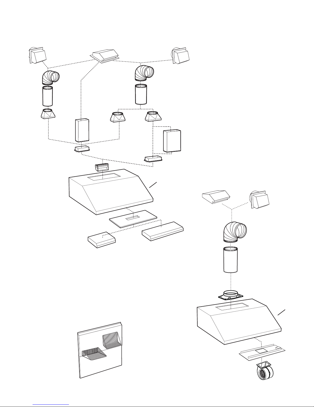
- UP26M SERIES RANGE HOOD SYSTEM -
INTERIOR BLOWERS
MODEL 647
(7” ROUND WALL CAP)
ODEL 415
M
7” ROUND
ADJUSTABLE
ELBOW
(OPTIONAL)
ODEL 407
M
(7” ROUND—
2 FT SECTIONS)
MODEL 412
TRANSITION
(3¼” X 10” TO 7”)
STANDARD
3¼” X 10”
A
DAPTER/DAMPER 3¼” X 10”
(SUPPLIED WITH P5 AND P8
BLOWERS)
(VERTICAL EXHAUST ONLY)
(SUPPLIED WITH P5 AND P8 BLOWERS)
DUCT
FLOW DEVIATOR
MODEL 634 OR 644
(ROOF CAP)
8” ROUND ADJUSTABLE
ELBOW (OPTIONAL)
8” R
STANDARD
MODEL 413
TRANSITION
(3¼” X 10” TO 8”)
OUND
DUCT
(8” ROUND WALL CAP)
ODEL 459 TRANSITION
M
(3¼” X 14” TO 8”)
A
DAPTER/DAMPER
3¼” X 14”
(SUPPLIED WITH P8 BLOWER)
UP26M HOOD
ODEL 643
M
STANDARD
3¼” X 14” DUCT
MODEL 634 OR 644
(ROOF CAP)
MODEL 643
(8” ROUND WALL CAP)
(SUPPLIED WITH P5 AND P8 BLOWERS)
MODEL P5
SINGLE-BLOWER (500 CFM)
BACKSPLASH (RMP SERIES)
(STAINLESS STEEL WALL COVERING
WITH WARMING SHELVES. OPTIONAL)
OUGH-IN KIT
R
ODEL P8 DUAL-BLOWER (900 CFM)
M
FOR USE WITH 36” HOODS OR WIDER
NOTE: The dual blower P8 must
be installed with 3¼” x 14”
duct. If it is impossible to
connect the dual blower P8
to a 3¼” x 14” duct, use a
3¼” x 10” duct. In that case,
the blower performance will
be decreased by 25%.
(SUPPLIED WITH P3, P6 AND IQ6 BLOWERS)
8” ROUND ADJUSTABLE
ELBOW (OPTIONAL)
8” ROUND
STANDARD DUCT
8” ROUND ADAPTER/DAMPER
(SUPPLIED WITH P3, P6 AND
IQ6 BLOWERS)
UP26M HOOD
ROUGH-IN KIT
HL0220
MODELS P3 (300 CFM), P6 (600 CFM)
OR IQ6 (600 CFM) SINGLE BLOWER
3
Page 4
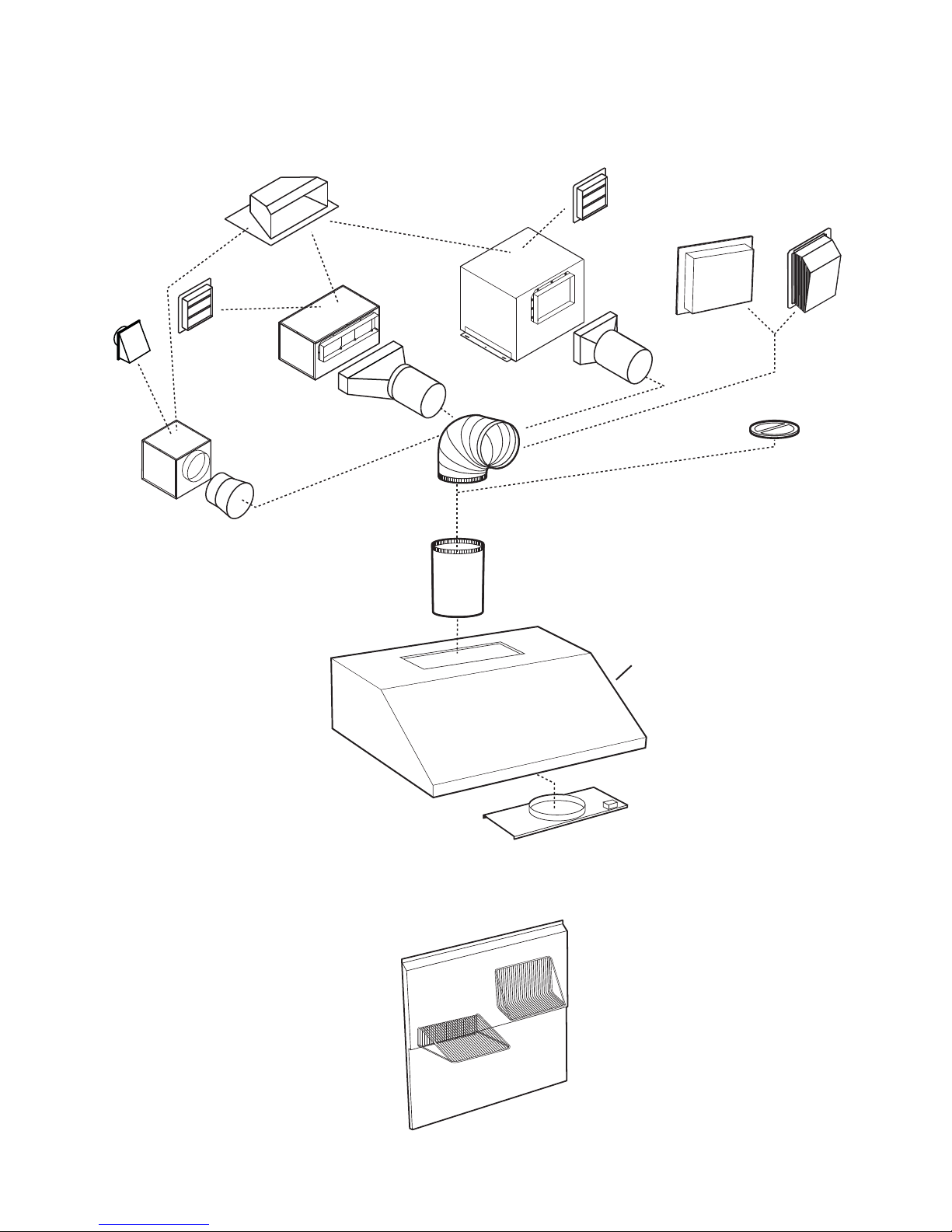
- UP26M SERIES RANGE HOOD SYSTEM -
IN-LINE AND EXTERIOR BLOWERS
MODEL 643
(8” ROUND
WALL
CAP)
MODEL ILB3 (280 CFM)
IN-LINE BLOWER
(INCLUDES ONE 8” TO 10”
ROUND TRANSITION)
M
ODEL 437
IGH CAPACITY ROOF CAP )
(H
ODEL 441
M
(10” ROUND
WALL CAP)
MODEL ILB6 (600 CFM)
IN-LINE BLOWER
(INCLUDES TWO 4½” X 18½”
TO 10’’ ROUND TRANSITIONS)
ADJUSTABLE ELBOW)—
ODEL ILB9 (800 CFM)
M
OR ILB11 (1100 CFM)
IN-LINE BLOWER
(INCLUDES TWO 8” X 12” TO
10’’
ROUND TRANSITIONS)
ODEL 418
M
(10” ROUND
OPTIONAL
MODEL 441
(10” R
MODEL 410
(10” ROUND DUCT
—2FT. SECTIONS)
OUND WALL CAP)
MODEL EB6 (600 CFM)
OR EB9 (900 CFM)
EXTERIOR BLOWER
(RECOMMENDED FOR USE
WITH EXTERIOR BLOWERS)
MODEL EB12 (1200 CFM)
OR EB15 (1500 CFM)
EXTERIOR BLOWER
MODEL 421
(10” ROUND VERT.
IN-LINE DAMPER)
RMP SERIES BACKSPLASH
(STAINLESS STEEL WALL
COVERING WITH WARMING
SHELVES. OPTIONAL)
UP26M
HOOD
N-LINE AND EXTERIOR BLOWER ROUGH-IN KIT
I
(INCLUDED WITH EB6, EB9, EB12, EB15,
ILB3, ILB6, ILB9 AND ILB11 BLOWERS).
HL0071
4
Page 5
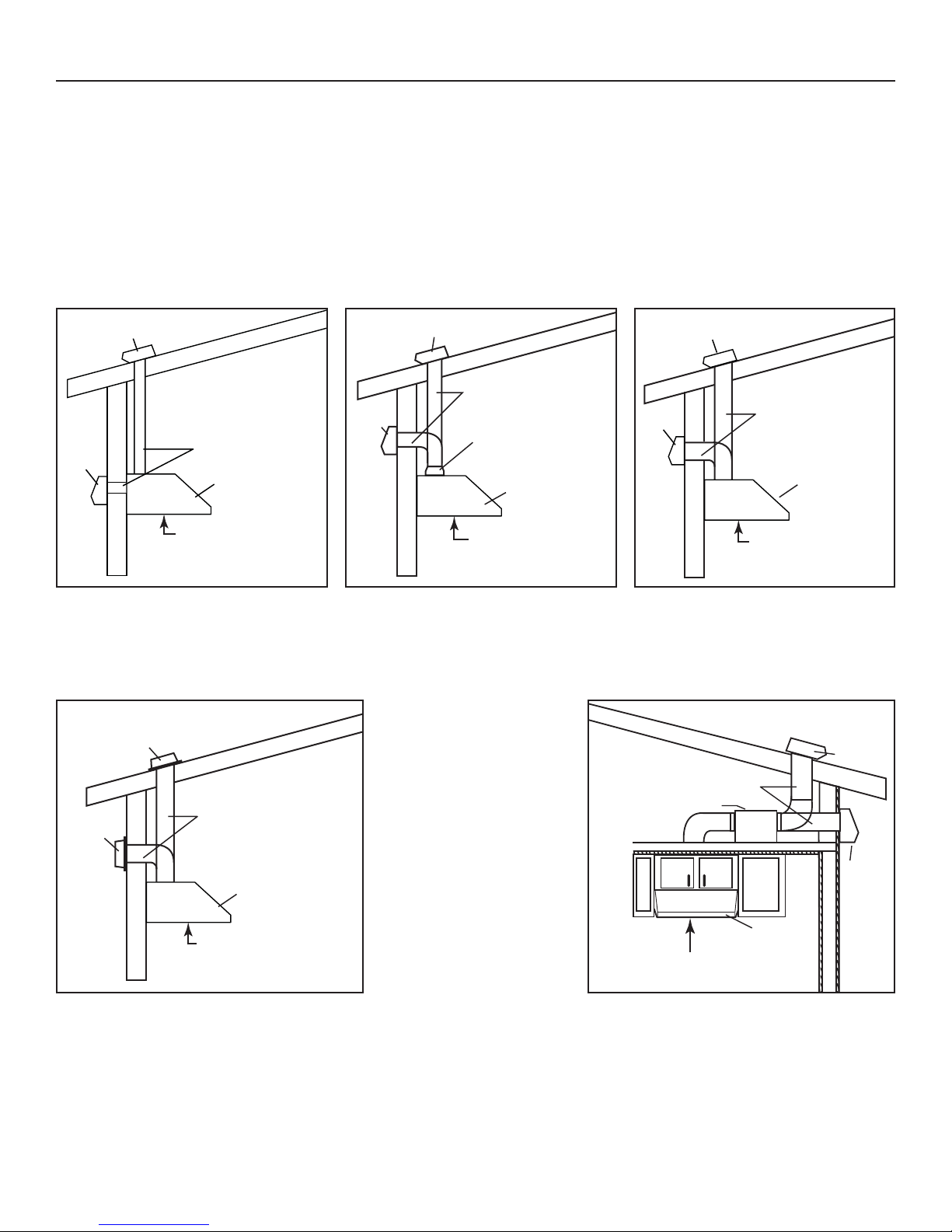
1. SELECT BLOWER OPTION AND INSTALL DUCTWORK
3¼” x 10”
OR 3¼” x 14”
HH0213A
Either an interior or exterior blower or in-line blower may be used with this hood. The Best UP26M must be installed with blower models iQ6,
P3, P5, P6, P8, ILB3, ILB6, ILB9, ILB11, EB6, EB9, EB12 or EB15 only. Other blowers cannot be substituted. (Blowers sold separately).
Plan where and how the ductwork will be installed.
If installing in-line blower, refer to instructions packed with in-line blower and follow steps 1 up to 3, 5, 8, 11, 12, 16 and up of this
manual.
Install proper-sized ductwork, elbow(s) and roof or wall cap for the type of blower you are installing. If using 7” or 8” round ducts, use a
transition. Use 2” metal foil duct tape to seal duct joints.
The minimum hood distance above cooktop must not be less than 24”. A maximum of 36” above cooktop is highly recommended
for best capture of cooking impurities.
Distances over 36” are at the installer and users discretion.
ROOF CAP
WALL
CAP
HOOD
24” TO 36”
ABOVE COOKING SURFACE
MODEL P5 (SINGLE) OR P8 (DOUBLE)
INTERIOR BLOWER
TYPICAL RECTANGULAR DUCTWORK
EXTERIOR BLOWER
EXTERIOR
BLOWER
10” ROUND DUCT
ROOF CAP
7” OR 8”
WALL
CAP
HH0214A
ROUND DUCT
3¼” X 10” TO 7”
OR 8” TRANSITION
X 14” TO 8”
OR 3¼”
TRANSITION
HOOD
24” TO 36”
ABOVE COOKING SURFACE
MODEL P5 (SINGLE) OR P8 (DOUBLE)
INTERIOR BLOWER
7” OR 8” ROUND DUCTWORK
(
EXCEPT HLB3, 8’’ ROUND DUCT)
ROOF CAP
WALL
CAP
HH0215A
ABOVE COOKING SURFACE
8” ROUND DUCT
24” TO 36”
MODEL P3, P6 or iQ6 (SINGLE)
INTERIOR BLOWER
8” ROUND DUCTWORK
10” ROUND DUCT
IN-LINE BLOWER
HOOD
ROOF CAP
HOOD
24” TO 36”
ABOVE COOKING SURFACE
HH0217A
MODEL EB6, EB9, EB12 OR EB15
EXTERIOR BLOWER
TYPICAL DUCTWORK
WALL
CAP
HOOD
ABOVE COOKING SURFACE
HH0212A
24” TO 36”
MODEL ILB3, ILB6, ILB9 OR ILB11
IN-LINE BLOWER
TYPICAL DUCTWORK
5
Page 6
2. PREPARE INSTALLATION
!
A
WARNING
When performing installation, servicing or cleaning the unit, it is recommended to wear safety glasses and gloves.
NOTE: Before proceeding to the installation, check the contents of the box. If items are missing or damaged, contact the manufacturer.
Make sure that the following items are included:
- Range hood
- Accessories: • Hybrid baffle filters with handles
• Shielded halogen bulbs (120 V, 50 W, MR16 with GU10 base or PAR16 with GU10 base)
• Bag of parts including: 4 lock nuts no. 10-32, 1 wire clamp LP16-AP, 2 no. 6 x 1/2” screws,
Parts sold separately:
• Interior blower Model P5 or P8 includes blower, rough-in kit, flow deviator and 3¼” x 10” or 3¼” x 14” adapter
• Interior blower Model iQ6, P3 or P6 includes blower, rough-in kit, adapter/damper
• In-line blower assembly ILB3, ILB6, ILB9 or ILB11 (all include transition(s) and rough-in plate)
• Exterior blower assembly EB6, EB9, EB12 or EB15 (all include rough-in plate)
• Backsplash (optional)
• Transitions, duct, elbows, dampers, wall and roof caps. Refer to pages 3 and 4 for a complete list of venting options and model numbers.
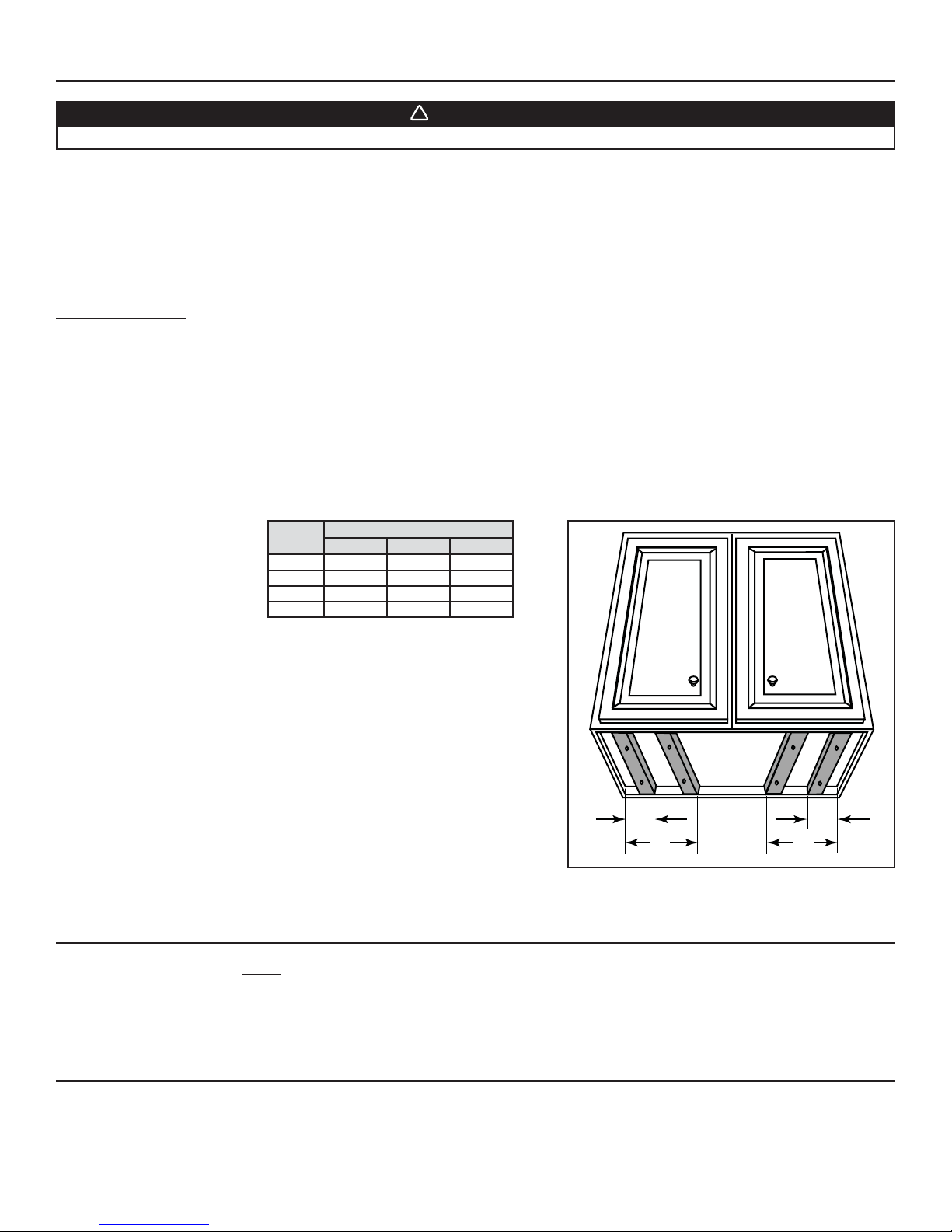
NOTE: For cabinets with recessed bottom, attach wood filler strips (not included) on each sides, as shown below. Use two 2-inch wide
strips for 30” wide hoods, and four 2-inch wide strips for wider hoods, cut to length. See below for wood filler strip locations.
2 wire connectors no. 74B, 6 no. 8 x 3/8”, 8 double threaded screws 6-12 x 1/2”
HOOD
WIDTHS
30” 2” N/A N/A
36” 2” 4½” 4½”
42” 2” 7¼” 8¼”
48" 4” 10¼” 11¼”
LOCATIONS
ABC
A
HD0079
B C
3. INSTALL BACKSPLASH (OPTIONAL)
Backsplash must be installed before the hood shell because the hood shell covers the backsplash top mounting screws. In order to be
able to install the backsplash, ensure to have at least 18” clearance between bottom of hood and range control panel or cooktop. (See
instructions packed with backsplash.)
4. SELECT BLOWER OPTION (EXTERIOR OR INTERIOR)
INTERIOR BLOWER: Follow all subsequent steps of this manual.
EXTERIOR BLOWER: Refer to instructions packed with exterior blower and follow steps 5, 8, 11,12, 16 and up of the present manual.
6
Page 7
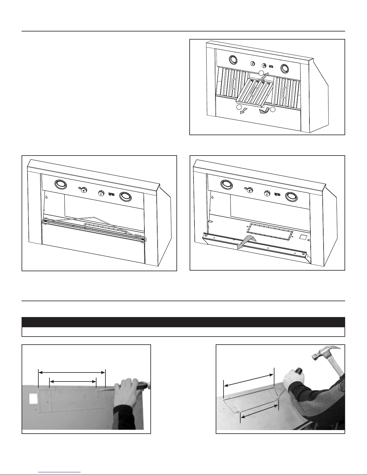
5. REMOVE FILTERS AND BOTTOM PANEL (ALL BLOWERS)
Lay the hood flat on a table. Use a piece of cardboard to avoid
damaging the table or the hood.
Remove tape on filters. Remove filters from hood and set aside.
NOTE: It is recommended to start with the center one(s).
HD0544
Remove bottom panel both retaining screws. Set bottom panel and screws aside.
RETAINING SCREWS
BOTTOM PANEL
1
3
2
HD0541
HD0542
6. CHOOSE THE OPENING (P5 AND P8 BLOWERS ONLY)
Remove the knockout for the chosen opening (horizontal at the back of the hood or vertical on rough-in plate). See pictures below.
CAUTION
If using P5 blower, remove 10” wide knockout. If using P8 blower, remove either 10” or 14” wide knockout.
14” KNOCKOUT
10” KNOCKOUT
HD0076
Removing horizontal knockout opening on back of hood.
HD0077
KNOCKOUT
”
14
KNOCKOUT
10”
Removing vertical knockout opening on rough-in plate.
7
Page 8
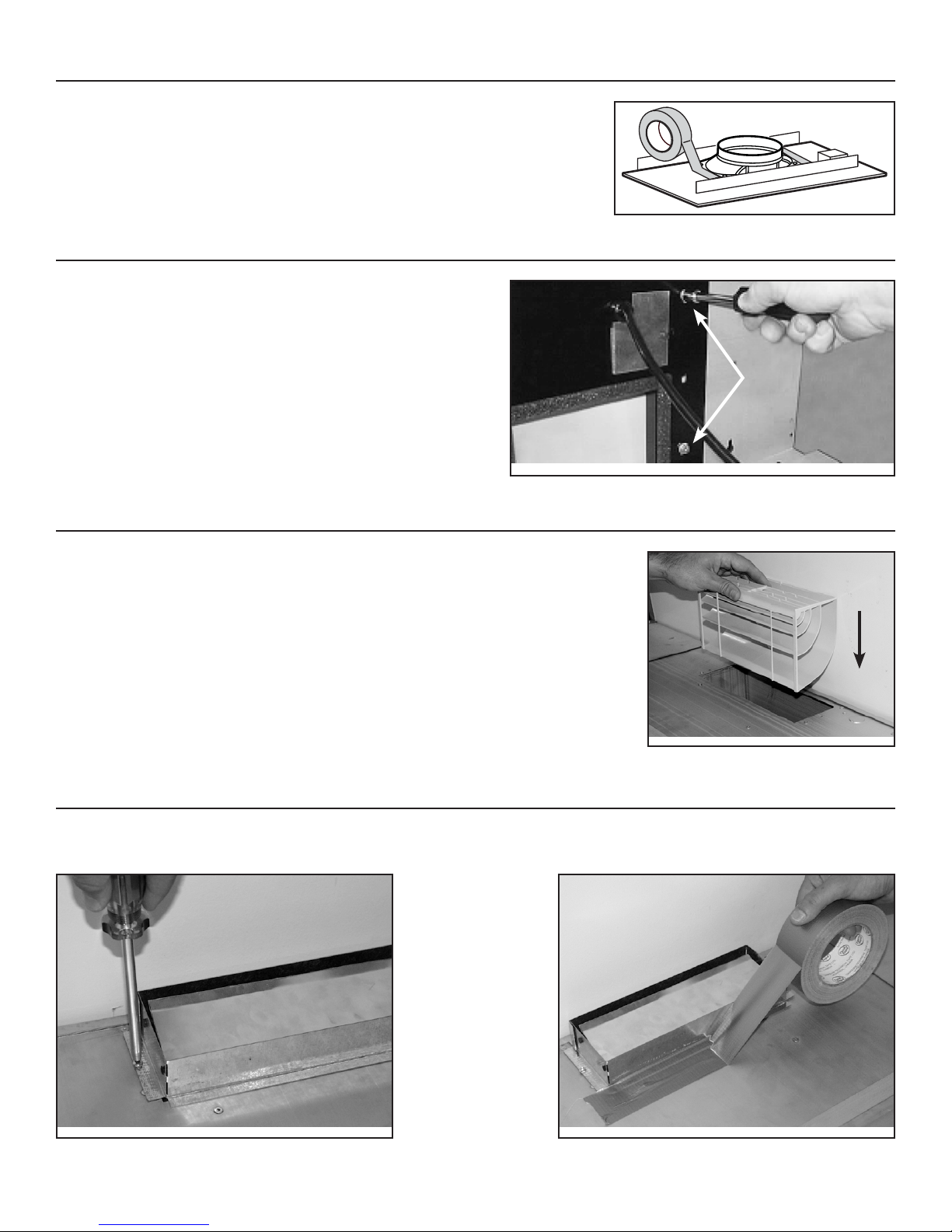
7. INSTALL THE ADAPTER/DAMPER (P3, P6 AND IQ6 BLOWERS ONLY)
Attach 8” round adapter/damper to blower rough-in plate.
Use metal duct tape to make all joints secure and air-tight.
HO0196
8. INSTALL THE ROUGH-IN PLATE (ALL BLOWERS)
BLOWER PLATE
INTERIOR BLOWER: Secure the rough-in plate (provided with the
blower) inside the hood with four lock nuts. See
picture at right.
EXTERIOR OR IN-LINE BLOWER: Refer to instructions included with
exterior or in-line blower rough-in kit.
Secure the rough-in plate inside the
hood with four lock nuts.
HD0048
9. INSTALL THE DEVIATOR (P5 AND P8 BLOWERS, VERTICAL INSTALLATION ONLY)
LOCK NUTS
YOU MUST install the deviator if you choose to vent the hood vertically. Install the deviator as
shown.
NOTE: If installed correctly, the deviator will protrude about 1/8” above the rough-in plate.
HD0003
Inserting deviator into hood vertical opening.
10. INSTALL THE ADAPTER (P5 AND P8 BLOWERS ONLY)
Using provided screws, secure the adapter to the top (or back) of the hood. Seal the adapter to the hood using metal foil duct tape.
NOTE: For vertical exhaust, ensure that the damper pivot is located towards the front of the hood.
HD0005 HD0006
8
Page 9
!
11. INSTALL THE HOOD (ALL BLOWERS)
INTERIOR BLOWER
Run power cable to installation location. Place the hood to its location. Mark the position of the screws (smaller part of the key holes)
with a pen. Remove the hood and install the (8) 1/2” double thread screws leaving a 1/8” gap (4 screws for 30” hood). Remove wiring
cover, place the wire clamp, insert the cable in the hood and tighten the wire clamp to secure the cable. Place the hood under the
cabinet and slide it in position. Make sure the adapter/damper assembly enters the ducting. Secure the hood by tightening the screws
completely.
HD0043
IN-LINE OR EXTERIOR BLOWER
Run power cable to installation location. Place the hood to its location. Mark the position of the screws (smaller part of the key holes)
with a pen. Remove the hood and install the (8) 1/2” double thread screws leaving a 1/8” gap (4 screws for 30” hood). Remove wiring
cover on top of the hood and connect wiring (see instructions included with exterior blower). Place the hood under the cabinet and
slide it in position. Secure the hood by tightening the screws completely.
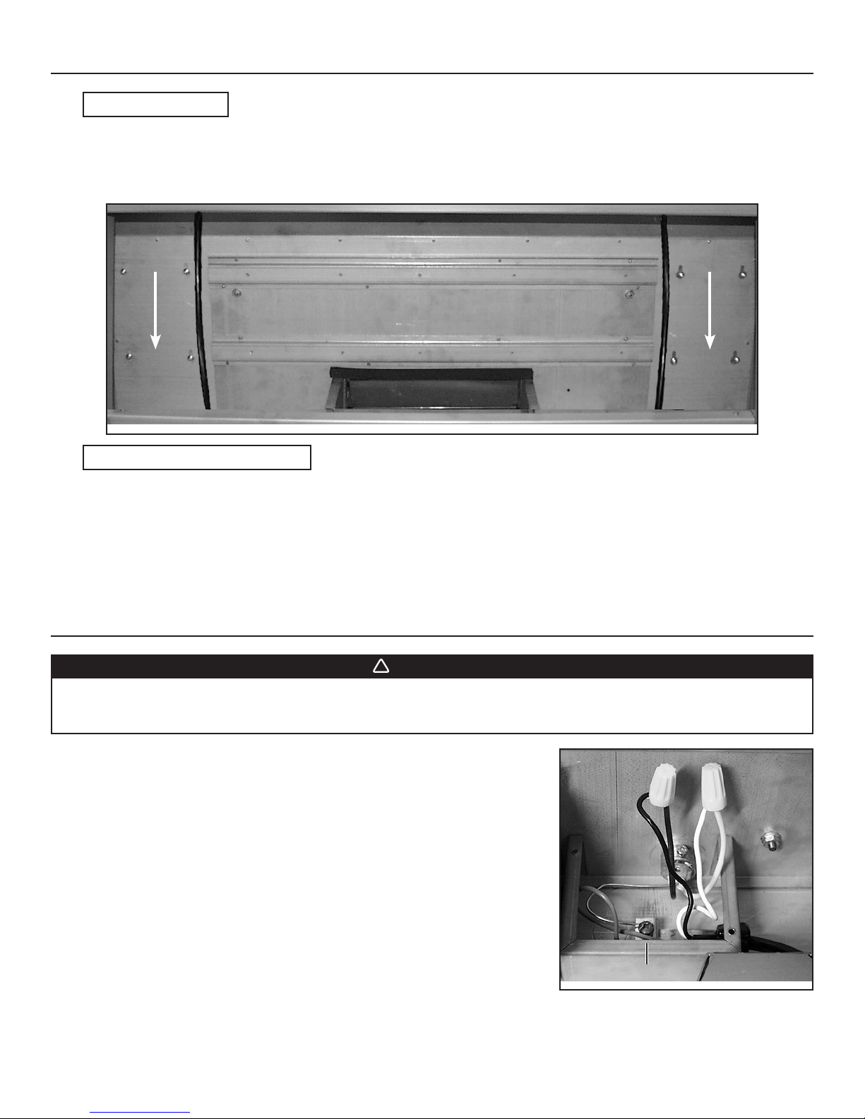
12. CONNECT WIRING (ALL BLOWERS)
WARNING
Risk of electric shock. Electrical wiring must be done by qualified personnel in accordance with all applicable
codes and standards. Before connecting wires, switch power off at service panel and lock service disconnecting
means to prevent power to be switched on accidentally.
INTERIOR BLOWER: Connect cable into wiring box using wire connectors.
Connect wires as follow: BLACK to BLACK, WHITE to WHITE and
GREEN or bare wire under ground screw. Reinstall wiring cover.
DO NOT FORGET TO CONNECT THE GROUND.
IN-LINE OR EXTERIOR BLOWER: Remove rough-in plate wiring cover and connect wiring (see instructions included with in-line or
exterior blower).
HE0012
GROUND SCREW
9
Page 10
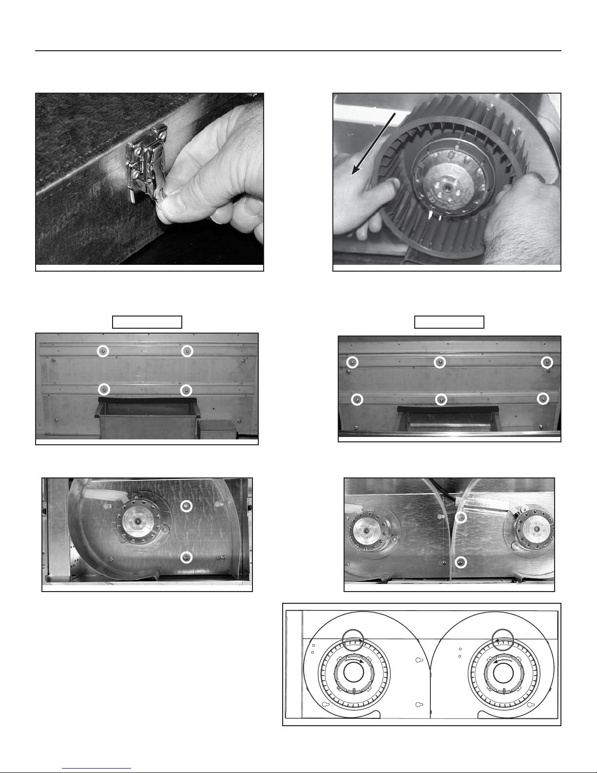
13. INSTALL THE BLOWER (P5 AND P8 BLOWERS ONLY)
The blower must be installed to the rough-in plate using four 3/8” screws. Remove the cover from the blower assembly. Remove the
impeller(s) by pulling it (them) out gently (see pictures below).
HD0021
HD0022
Install screws into the location as shown in the pictures below (P5 or P8 blower). Do not tighten screws down fully, leave a 1/8” gap. Hang
blower unit onto blower plate (screws through the large part of the keyhole). Slide the blower to its position (screws in the small part of the
keyhole). Tighten the screws.
HD0044
P5 BLOWER
HD0045
P8 BLOWER
Secure the blower by installing 2 more screws into the locations shown in the pictures below (P5 or P8 blower). Reinstall impeller(s) and
cover.
HD0080
FOR P8 DUAL BLOWER UNIT, ENSURE THE IMPELLERS
ARE CORRECTLY INSTALLED; THE HOOD WILL NOT
WORK PROPERLY IF REVERSED. Both impellers are
different in the dual blower, one rotates clockwise and the other
counterclockwise. Each wheel and motor have an arrow and
a number on them, you have to match them correctly (see
drawing at right).
HD0023
10
HD0081
1
FRONT
HD0023
21
2
Page 11
13. INSTALL THE BLOWER (P5 AND P8 BLOWERS ONLY) (CONT'D)
!
!
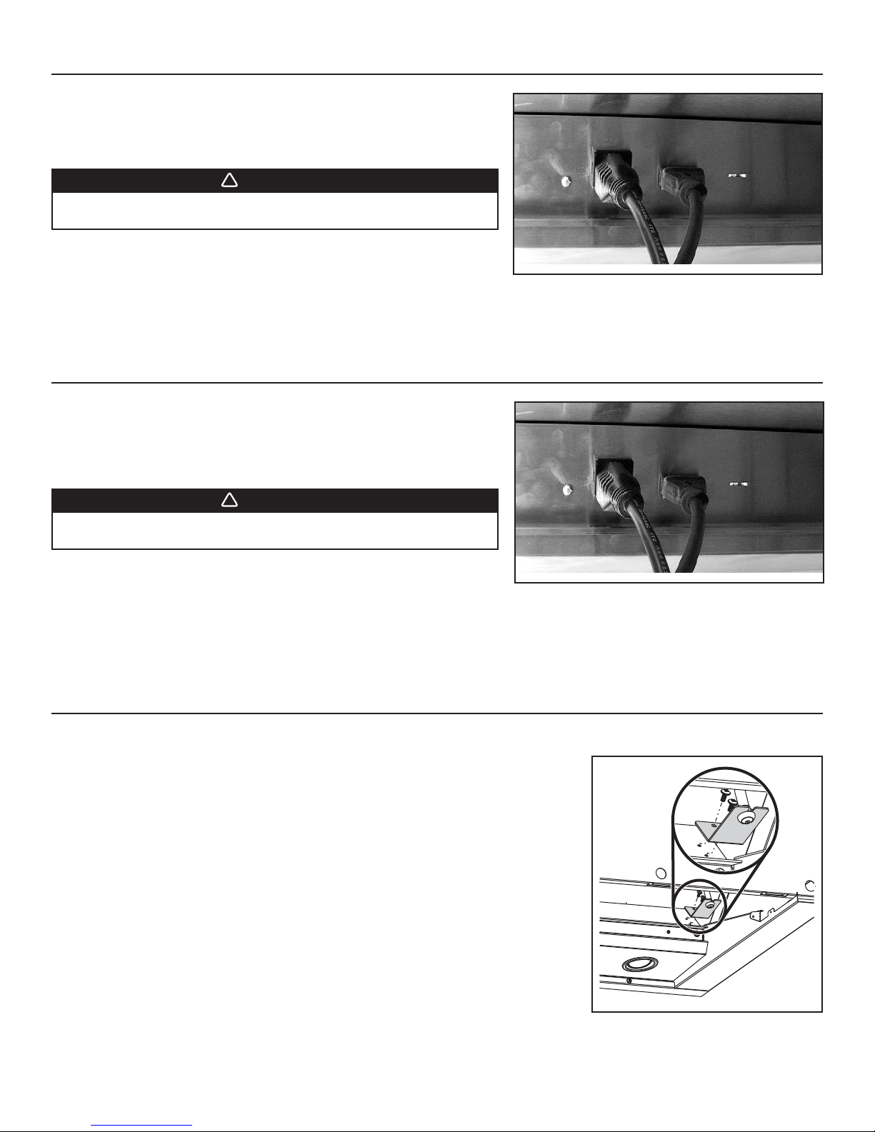
Plug the power supply to the 3-prong male connector (A) and the blower unit into
the 2-prong female receptacle (B) inside the hood.
WARNING
Never plug the 2-prong blower cord to the 3-prong power supply
cord.
HE0003
14. INSTALL THE BLOWER (P3, P6, IQ6 AND EXTERIOR BLOWERS ONLY)
Refer to instructions included with blower.
Once the blower is installed, plug the power supply to the 3-prong male connector (A)
and the blower unit into the 2-prong female receptacle (B) inside the hood.
WARNING
Never plug the 2-prong blower cord to the 3-prong power supply
cord.
A
B
A
B
HE0003
15. INSTALL THE CALIBRATION BUTTON BRACKET IN THE HOOD
(iQ6 INTERIOR BLOWER ONLY)
The iQ6 blower is equipped with a calibration button already mounted to its own bracket. Install
this bracket in the hood, using 2 screws provided with iQ6 interior blower.
See additional details in the iQ6 blower instructions included with the blower.
HD0007
11
Page 12
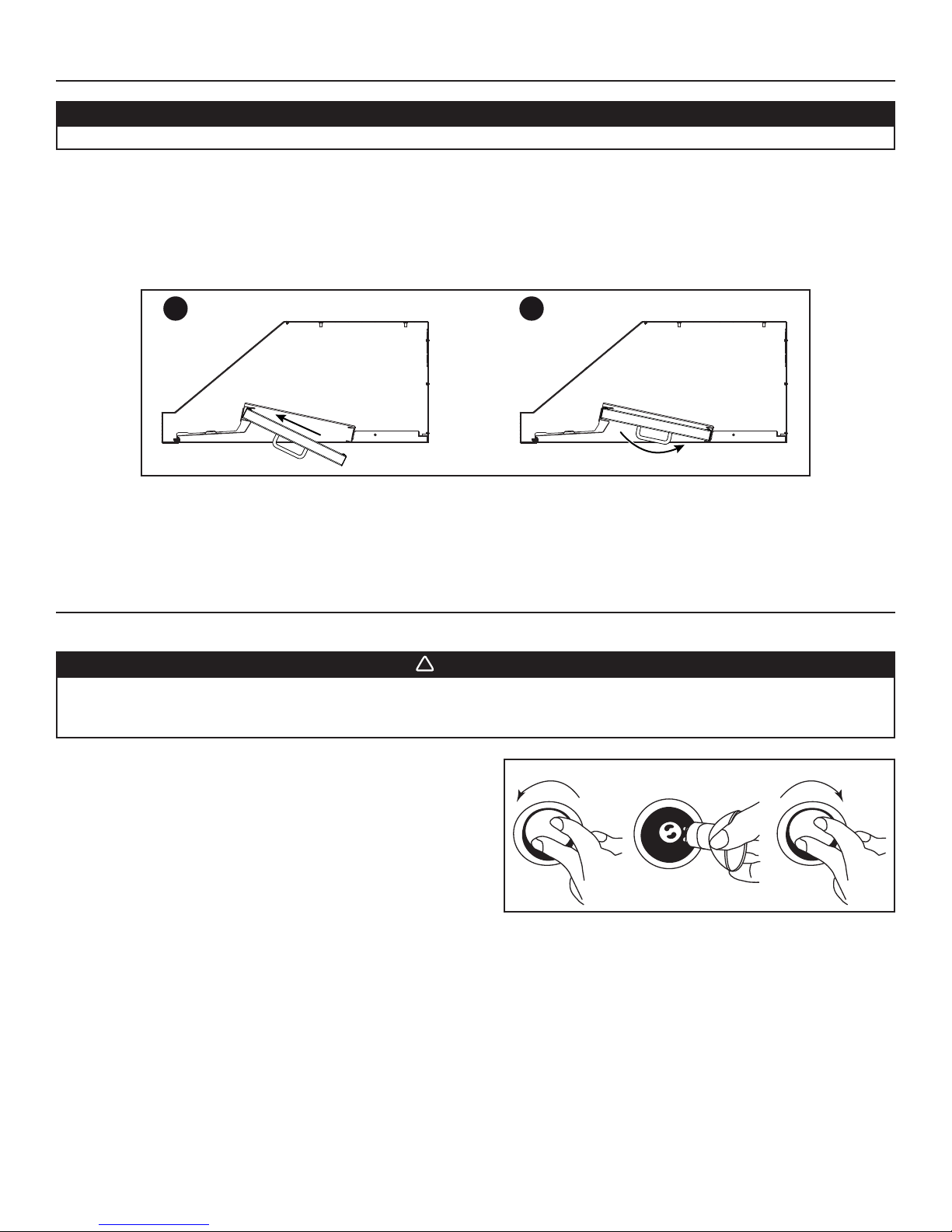
16. REINSTALL BOTTOM PANEL AND HYBRID BAFFLE FILTERS
!
CAUTION
Remove protective plastic film covering filters before installing them.
Reinstall bottom panel using both retaining screws removed in step 5.
Reinstall filters. It is recommended to install side filters first and finish with center one(s).
Insert the end with filter spring clip of hybrid baffle filter into the upper channel of the hood.
Raise the other end toward the inside and insert in the grease drip rail of the hood.
Replacement filters are available from your dealer. See label inside hood for part number.
1
HD0543
2
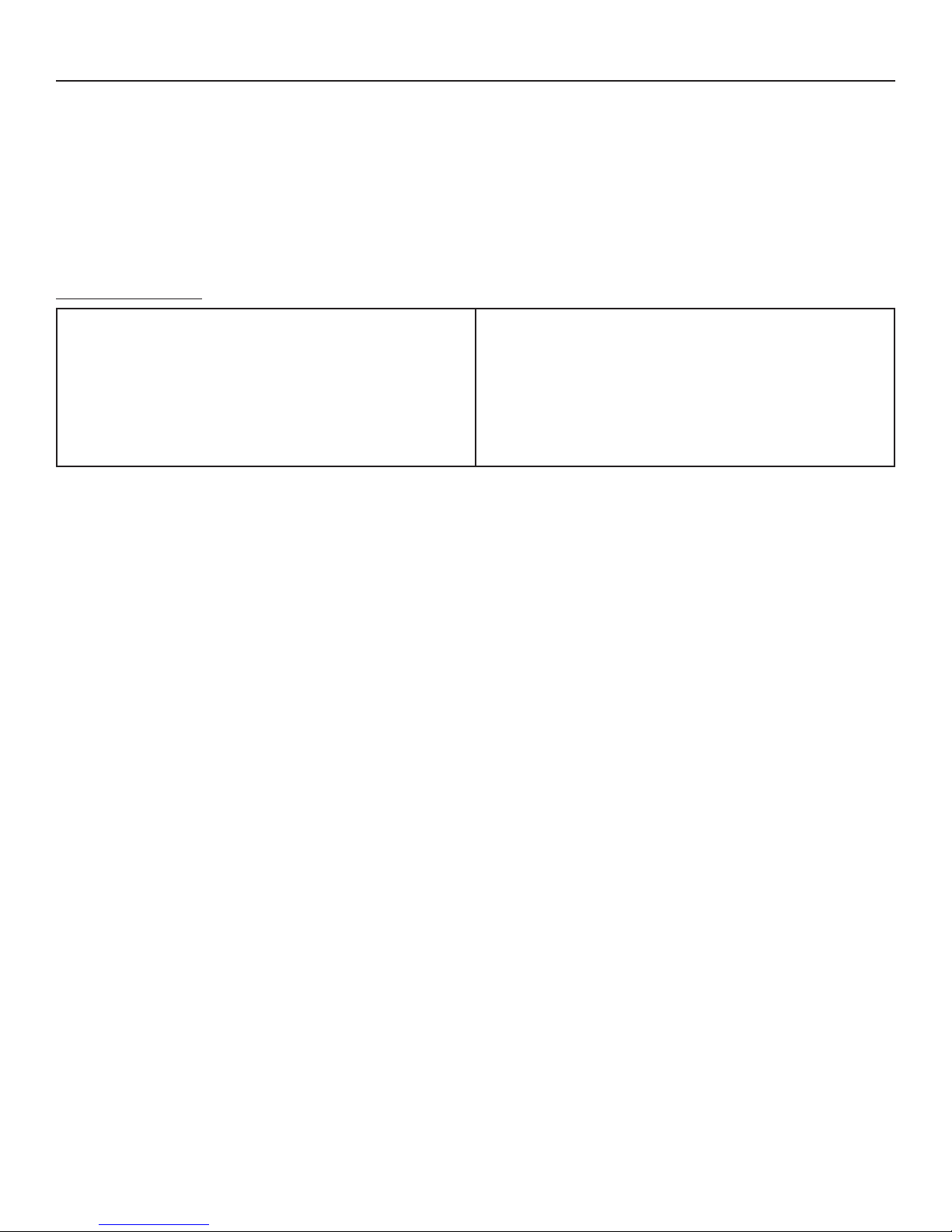
17. LIGHT BULBS REPLACEMENT
This hood requires 120 V, 50 W, MR16 with GU10 base or PAR16 with GU10 base, shielded halogen lamps (included).
WARNING
Do not touch lamps during or soon after operation. Burns may occur. In order to prevent the risk of personal injury,
only install shielded halogen lamps. Also, never install a cool beam, a dichroïc lamp, a lamp not suitable for use in
recessed luminaires or identified for use in enclosed fixtures.
1. To remove lamps, gently push upwards and turn counterclockwise to
disengage bulb leads from their grooves.
NOTE: To ease removal of the bulbs, use a rubber dishwashing
glove or use suction cup tool available from Best. Contact
Best Customer Service at 1-800-558-1711 to order suction
cup tool, part no. 99526707.
2. Install the new lamps by placing the bulb leads into their grooves in
the socket.
3. Gently push upwards and turn clockwise until secure.
12 3
HO0089
12
Page 13
18. USE AND CARE
Hybrid baffle filters and impeller(s)*
The hybrid baffle filters, impeller(s) and grease rail should be cleaned frequently. Use a warm detergent solution. Wash more often if your
cooking style generates greater grease — like frying foods or wok cooking.
Remove filters by pushing filters towards the front of hood and rotating filters downward. Hybrid baffle filters and impeller(s) are dishwasher
safe.
Clean all-metal filters in the dishwasher using a non-phosphate detergent. Discoloration of the filter may occur if using phosphate detergent
or as a result of local water conditions — but this will not affect filter performance. This discoloration is not covered by the warranty.
* Impeller(s) only on P5 and P8 blowers.
Hood cleaning
Stainless steel cleaning:
Do:
• Regularly wash with clean cloth or rag soaked with warm water
and mild soap or liquid dish detergent.
• Always clean in the direction of original polish lines.
• Always rinse well with clear water (2 or 3 times) after cleaning.
Wipe dry completely.
• You may also use a specialized household stainless steel
cleaner.
Avoid when choosing a detergent:
- Any cleaners that contain bleach will attack stainless steel.
- Any products containing: chloride, fluoride, iodide, bromide will deteriorate surfaces rapidly.
- Any combustible products used for cleaning such as acetone, alcohol, ether, benzol, etc., are highly explosive and should never be
used close to a range.
Don’t:
• Use any steel or stainless steel wool or any other scrapers to
remove stubborn dirt.
• Use any harsh or abrasive cleansers.
• Allow dirt to accumulate.
• Let plaster dust or any other construction residues reach the
hood. During construction/renovation, cover the hood to make
sure no dust sticks to stainless steel surface.
13
Page 14
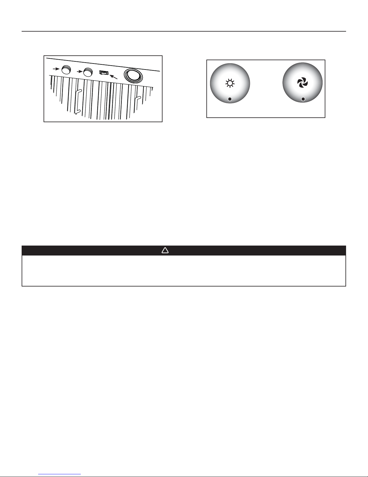
19. OPERATION
!
Always turn your hood on before you begin cooking to establish an air flow in the kitchen. Let the blower run for a few minutes to clear the
air after you turn off the range. This will help keep the whole kitchen cleaner and brighter.
1
2
3
HC0038
1) HALOGEN LIGHT KNOB
2) BLOWER SPEED CONTROL KNOB
3) ON/OFF BLOWER SWITCH
COOKTOP LIGHTING (HALOGEN)
A rotary 3-position knob (1) controls the halogen lights (OFF - low intensity - high intensity).
BLOWER
The blower is operated using two controls.
Use the on/off rocker switch (3) to start and stop the blower. When turned on, the blower operates at the previous setting of the speed
control (2).
Turn the speed control knob counterclockwise to increase blower speed – clockwise to decrease speed.
HEAT SENTRY™
This hood is equipped with a Heat Sentry™ thermostat. This thermostat is a device that will turn on or speed up the blower if it senses
excessive heat above the cooking surface.
1) If blower is OFF - it turns blower ON to HIGH speed.
2) If blower is ON at a lower speed setting – it turns the blower up to HIGH speed.
HC0039
1) HALOGEN LIGHT KNOB
2) BLOWER SPEED CONTROL KNOB
AB
WARNING
The HEAT SENTRY can start the blower during a range top fire or other excessive heat situations even if the hood
is turned off. In this case, it is impossible to turn the blower OFF with blower switch. If you must stop the blower,
unplug the blower power cord (located behind the filters) from the hood by pulling on its 2-prong connector; do
not pull on the wire.
When the temperature level drops to normal, the blower will return to its original setting.
14
Page 15
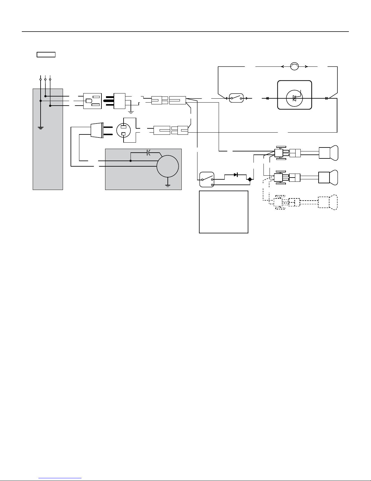
20. WIRING DIAGRAMS
INTERIOR BLOWER
120 VAC
NEUTRAL
GROUND
LINE
BLK
G
W
BLK
HS
HERMOSTAT
T
BLU BLU
S
FAN SWITCH
W
BLK
W
BLK
PEED CONTROL
ROUGH-IN PLATE
HE0187A
BLK
W
INTERNAL BLOWER ASSEMBLY
W
BLK
M
BLK
LAMP
SWITCH
COLOR CODE
BLK BLACK
BLU BLUE
G GREEN
W WHITE
Y YELLOW
BLK
W
W
Y
Y
W
Y
LAMP
LAMP
LAMP
15
Page 16

20. WIRING DIAGRAMS (CONT'D)
IN-LINE OR EXTERIOR BLOWER
120 VAC
GROUND
LINE
OUGH-IN PLATE
R
HE0188A
NEUTRAL
BLK
G
W
W
BLK
HS
HERMOSTAT
T
BLU BLU
S
FAN SWITCH
BLK
W
W
BLK
BLK
W
G
REMOTE BLOWER ASSEMBLY
M
BLK
W
BLK
LAMP
SWITCH
W
BLK
Y
W
W
PEED CONTROL
BLK
LAMPLAMP
Y
Y
COLOR CODE
BLK BLACK
LAMP
BLU BLUE
G GREEN
W WHITE
Y YELLOW
16
Page 17
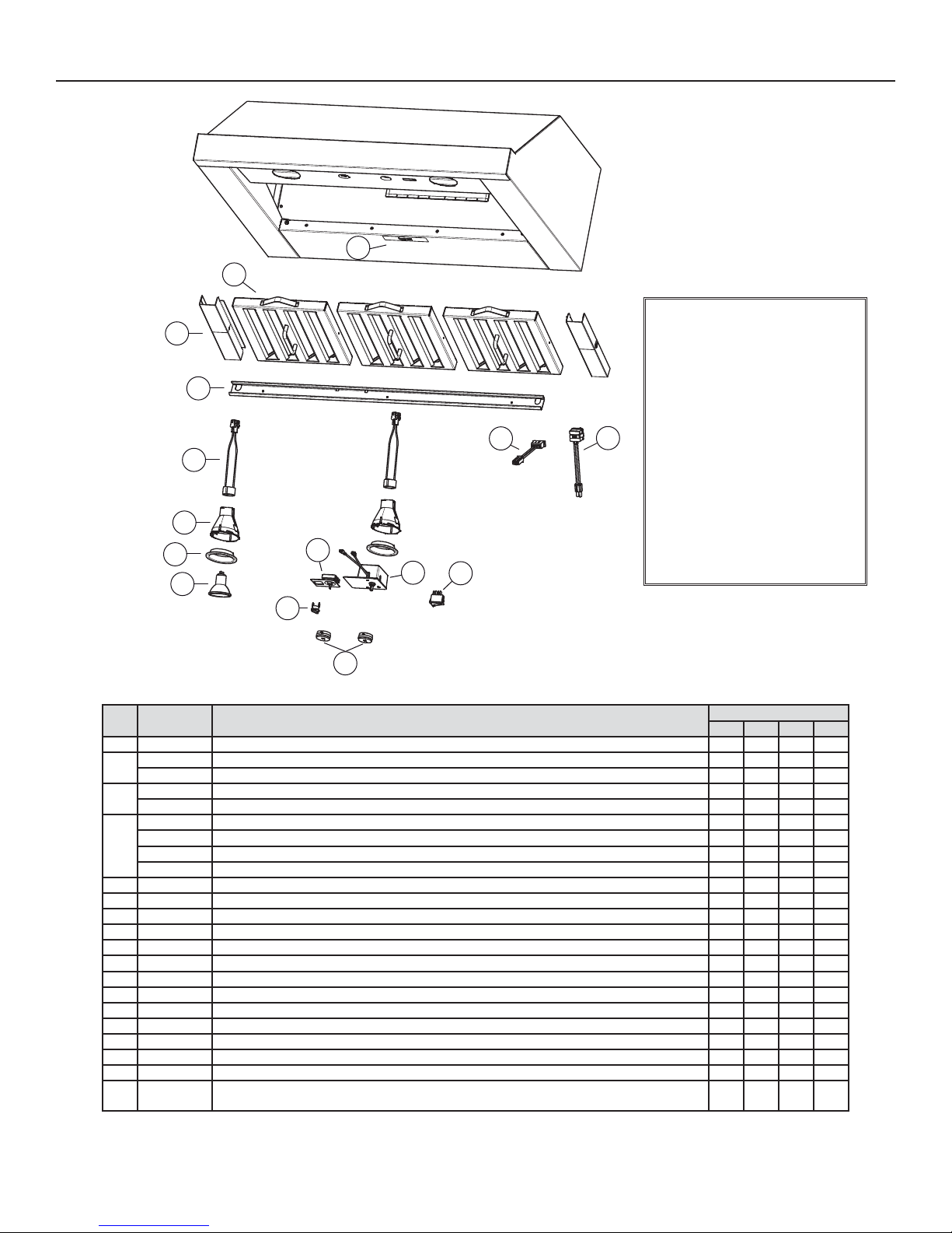
21. SERVICE PARTS
Model UP26M
2
3
4
5
6
7
8
10
11
1
REPLACEMENT PARTS AND REPAIRS
In order to ensure your unit remains in
good working condition, you must use
Broan-NuTone genuine replacement
parts only. Broan-NuTone genuine
replacement parts are specially
designed for each unit and are
manufactured to comply with all the
applicable certification standards and
maintain a high standard of safety.
Any third party replacement part
used may cause serious damage and
drastically reduce the performance
level of your unit, which will result
in premature failing. Broan-NuTone
recommends to contact a certified
service depot for all replacement
parts and repairs.
12
13
14
15
HL0221
KEY
PART NO.DESCRIPTION
NO.
1 SV05869 BEST LOGO 1111
SV13431 HYBRID BAFFLE FILTER 8.84" X 8.61" (INCLUDING HANDLE)-31-
2
SV13432 HYBRID BAFFLE FILTER 11.84" X 8.61" (INCLUDING HANDLE) 2-23
SV61691 F
3
SV61679 FILTER FILLER 3" (PAIR) ---1
SV61742 GREASE RAIL 30" 1--SV61743 G
4
SV61744 G
SV61745 GREASE RAIL 48" ---1
5 SV05917 S
6 SV09435 S
7 SV09434 LIGHT TRIM, STAINLESS STEEL 2233
8 SV05921 SHIELDED HALOGEN BULBS (50 W, 120 V, PAR16, GU10) 2233
9 SV08578 B
10 SV03435 THERMOSTAT 1111
11 SV08338 LIGHT SWITCH 1111
12 SV03501 SPEED CONTROL 1111
13 SV08548 BLOWER ROCKER SWITCH 1111
14 SV13923 FEMALE CONNECTOR 1111
15 SV13924 MALE CONNECTOR 1111
* SV17645 THERMOSTAT BRACKET 1111
* SV21517 INSTALLATION GUIDE 1111
* SV13278
ILTER FILLER 1.6" (PAIR)-11-
REASE RAIL 36" -1--
REASE RAIL 42" --1-
OCKET GU10 2233
OCKET HOLDER GU10 2233
LOWER AND LIGHT KNOBS (2 KNOBS) 1111
PARTS BAG: 4 LOCK NUTS NO. 10-32, 1 WIRE CLAMP LP16-AP, 2 NO. 6 X 1/2” SCREWS,
2 WIRE CONNECTORS NO. 74B, 6 NO. 8 X 3/8”, 8 DOUBLE THREADED SCREWS 6-12 X 1/2”
9
QTY. (HOOD WIDTH)
30" 36" 42" 48"
1111
* NOT SHOWN.
17
Page 18
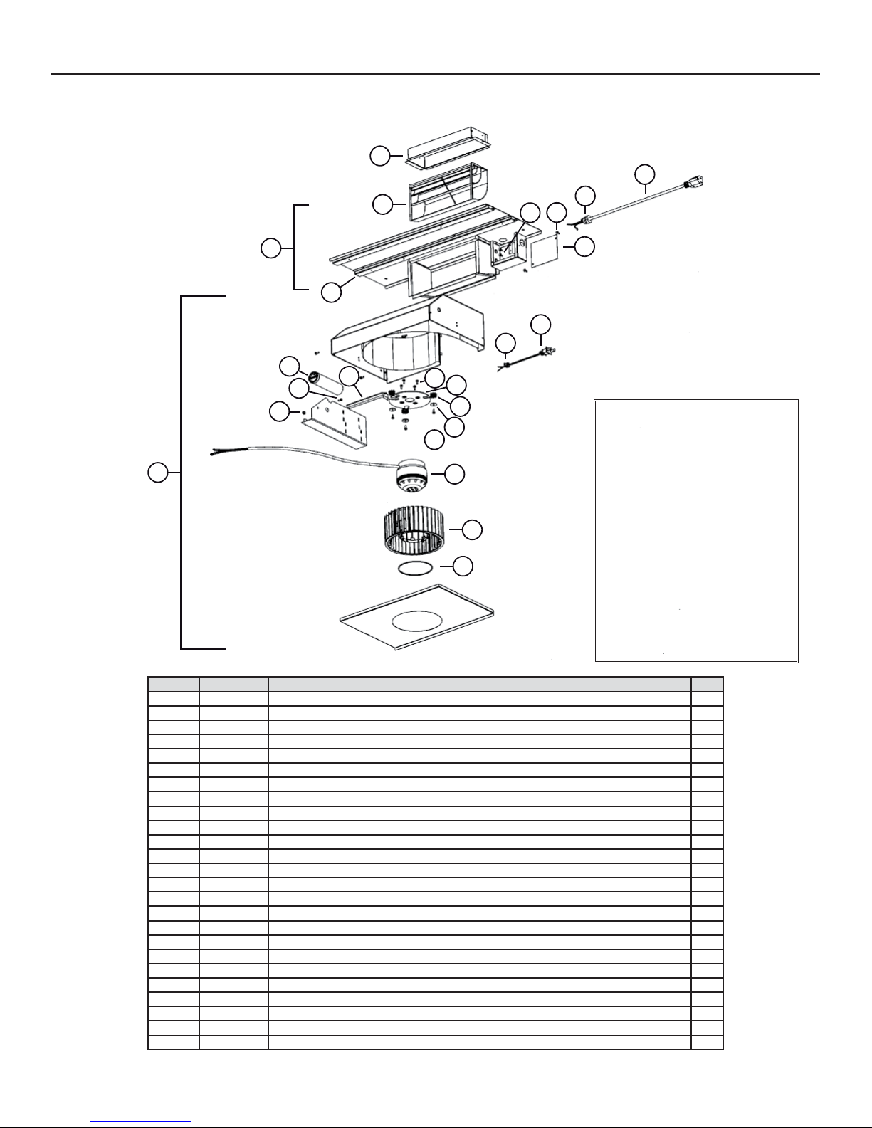
21. SERVICE PARTS (CONT'D)
SINGLE BLOWER/ROUGH-IN
(Model P5)
1
20
2
23
21
22
9
HL0021
3
19
4
18
17
5
5
6
8
7
16
6
15
13
12
14
10
11
REPLACEMENT PARTS AND REPAIRS
In order to ensure your unit remains in
good working condition, you must use
Broan-NuTone genuine replacement
parts only. Broan-NuTone genuine
replacement parts are specially
designed for each unit and are
manufactured to comply with all the
applicable certification standards and
maintain a high standard of safety.
Any third party replacement part
used may cause serious damage and
drastically reduce the performance
level of your unit, which will result
in premature failing. Broan-NuTone
recommends to contact a certified
service depot for all replacement
parts and repairs.
KEY NO.PART NO.DESCRIPTION QTY.
1 SV13296 ADAPTER/DAMPER 3¼” X 10” 1
2 SV03500 AIR DEFLECTOR 1
3 SV12997 SINGLE BLOWER ROUGH-IN PLATE ASSEMBLY 1
4 SV03577 FOAM 1/2” X 1/2” X 12” 1
5 SV02160 CAPACITOR 15 µF 1
6*M
7 SV01857 WIRE COVER 1
8*LOCK NUT NO. 6-32 1
9 SV14973 SINGLE BLOWER ASSEMBLY 1
10 SV01810 IMPELLER RING 1
11 SV03400 BLOWER IMPELLER 7.094” X 3.375” CW 1
12 SV01766 MOTOR 165 W CW 1
13 * WASHER 3/16” ID X 3/4” OD 3
14 SV02001 MOTOR GROMMET G-431-1 3
*8” TIE WRAP 2
15 SV11705 M
*W
16 SV01927 METRIC SCREW M4 X 6 MM PAN QUADREX 4
17 SV03495 STRAIN RELIEF FOR BLOWER POWER CORD 1
18 SV03494 36” BLOWER POWER CORD 1
19 SV13230 OUTLET BOX COVER 1
20 SV03496 POWER CORD, 120 VOLTS 1
21 SV00660 STRAIN RELIEF FOR POWER CORD 1
22 * SCREW NO. 8 X 3/8”, T/B, NO. 8 HEAD 2
23 * SCREW NO. 10-32 X 3/8”, TF, GREEN 2
* STANDARD HARDWARE—MAY BE PURCHASED LOCALLY.
ACHINE SCREW NO. 6-32 X 1/4” 4
OTOR MOUNT 1
IRE NO. 18 TEW BROWN X 10” 1
18
Page 19

21. SERVICE PARTS (CONT'D)
DUAL BLOWER/ROUGH-IN
(Model P8)
7
11
HL0022
KEY NO.PART NO.DESCRIPTION QTY.
1 SV14971 ADAPTER/DAMPER 3¼” X 14” 1
2 SV13296 A
3 SV03500 AIR DEFLECTOR 1
4 SV14975 DUAL BLOWER ROUGH-IN PLATE ASSEMBLY 1
5 SV03577 FOAM 1/2” X 1/2” X 12” 1
6*L
7 SV02160 C
8 SV01857 WIRE COVER 2
9 SV01766 MOTOR 165 W CW 1
10 SV03400 BLOWER IMPELLER, HOOD 7.094” X 3.375” CW 1
11 SV14974 DUAL BLOWER ASSEMBLY 1
12 SV01810 I
13 SV03399 BLOWER IMPELLER, HOOD 7.094” X 3.375” CCW 1
14 SV03457 MOTOR 165 W CCW 1
15 * WASHER 3/16” ID X 3/4” OD 6
16 SV11705 M
17 SV02001 MOTO R GROMMET G-431-1 6
18 SV01927 METRIC SCREW SCREW M4 X 6 MM PAN QUADREX 8
19 SV03495 STRAIN RELIEF FOR BLOWER CORD 1
20 SV03494 36” B
21 SV14960 OUTLET BOX COVER 1
22 SV03496 POWER CORD, 120 VOLTS 1
23 SV00660 STRAIN RELIEF FOR POWER CORD 1
24 * SCREW NO. 8 X 3/8”, T/B, NO. 8 HEAD 4
25 * SCREW NO. 10-32 X 3/8”, TF, GREEN 2
* STANDARD HARDWARE—MAY BE PURCHASED LOCALLY.
2
1
25
24
3
4
21
22
23
5
20
19
6
18
17
16
15
14
8
9
13
10
12
DAPTER/DAMPER 3¼” X 10” 1
OCK NUT NO. 6-32 1
APACITOR 15 µF 2
MPELLER RING 2
*8” T
*WIRE NO. 18 TEW BROWN X 10” 2
IE WRAP 4
OTOR MOUNT 2
LOWER POWER CORD 1
REPLACEMENT PARTS AND REPAIRS
In order to ensure your unit remains in
good working condition, you must use
Broan-NuTone genuine replacement
parts only. Broan-NuTone genuine
replacement parts are specially
designed for each unit and are
manufactured to comply with all the
applicable certification standards and
maintain a high standard of safety.
Any third party replacement part
used may cause serious damage and
drastically reduce the performance
level of your unit, which will result
in premature failing. Broan-NuTone
recommends to contact a certified
service depot for all replacement
parts and repairs.
19
Page 20

22. WARRANTY
ONE-YEAR LIMITED WARRANTY
Broan-NuTone LLC (Broan-NuTone) warrants to the original consumer purchaser of Best products that such products will be free
from defects in materials or workmanship for a period of one year from the date of original purchase. THERE ARE NO OTHER
WARRANTIES, EXPRESS OR IMPLIED, INCLUDING, BUT NOT LIMITED TO, IMPLIED WARRANTIES OR MERCHANT ABILITY OR
FITNESS FOR A PARTICULAR PURPOSE.
During this one-year period, Broan-NuTone will, at its option, repair or replace, without charge, any product or part which is found to be
defective under normal use and service.
THIS WARRANTY DOES NOT EXTEND TO FLUORESCENT LAMP STARTERS, TUBES, HALOGEN AND INCANDESCENT BULBS,
FUSES, FILTERS, DUCTS, ROOF CAPS, WALL CAPS AND OTHER ACCESSORIES FOR DUCTING. This warranty does not cover
(a) normal maintenance and service or (b) any products or parts which have been subject to misuse, negligence, accident, improper
maintenance or repair (other than by Broan-NuTone), faulty installation or installation contrary to recommended installation instructions.
The duration of any implied warranty is limited to the one-year period as specified for the express warranty. Some states or provinces
do not allow limitation on how long an implied warranty lasts, so the above limitation may not apply to you.
BROAN-NUTONE’S OBLIGATION TO REPAIR OR REPLACE, AT BROAN-NUTONE’S OPTION, SHALL BE THE PURCHASER’S
SOLE AND EXCLUSIVE REMEDY UNDER THIS WARRANTY. BROAN-NUTONE SHALL NOT BE LIABLE FOR INCIDENTAL,
CONSEQUENTIAL OR SPECIAL DAMAGES ARISING OUT OF OR IN CONNECTION WITH PRODUCT USE OR PERFORMANCE.
Some states or provinces do not allow the exclusion or limitation of incidental or consequential damages, so the above
limitation or exclusion may not apply to you.
This warranty gives you specific legal rights, and you may also have other rights, which vary from state to state or province to another.
This warranty supersedes all prior warranties.
To qualify for warranty service, you must (a) notify Broan-NuTone at the address or telephone number stated below, (b) give the model
number and part identification and (c) describe the nature of any defect in the product or part. At the time of requesting warranty service,
you must present evidence of the original purchase date.
In USA - Best
In Canada - Best
®
, 926 W. State Street, Hartford, WI 53027 (800-558-1711)
®
, 550 Lemire Blvd., Drummondville, QC, Canada, J2C 7W9 (866-737-7770)
www.BestRangeHoods.com
20
Page 21

GUIDE D’INSTALLATION
HB0029
! !
CONÇUE POUR USAGE DOMESTIQUE SEULEMENT
LIRE ET CONSERVER CES DIRECTIVES
INSTALLATEUR : LAISSER CE GUIDE AU PROPRIÉTAIRE.
PROPRIÉTAIRE : DIRECTIVES D’UTILISATION ET D’ENTRETIEN
BEST; Hartford, Wisconsin www.BestRangeHoods.com 800 558-1711
BEST; Drummondville, QC, Canada www.BestRangeHoods.com 866 737-7770
Pour enregistrer votre produit en ligne ou pour obtenir plus d’information, consultez notre site www.BestRangeHoods.com
SÉRIE UP26M
EN PAGES 28 ET 29.
SV21517 rév. 02
Page 22

!
AVERTISSEMENT
!
AVERTISSEMENT
AFIN DE RÉDUIRE LES RISQUES D’INCENDIE,
D’ÉLECTROCUTION OU DE BLESSURES CORPORELLES,
SUIVEZ LES DIRECTIVES SUIVANTES :
1. N’utilisez cet appareil que de la façon prévue par le
manufacturier. Si vous avez des questions, contactez le
manufacturier à l’adresse ou au numéro de téléphone indiqués
dans la garantie.
2. Avant de réparer ou de nettoyer l’appareil, couper l’alimentation
électrique en verrouillant le panneau de distribution afin
d’éviter sa remise en marche accidentelle. Si le panneau de
distribution ne peut être verrouillé, y fixer un avertissement en
évidence, telle qu’une étiquette de couleur vive.
3. Les travaux d’installation et de raccordement électrique doivent
être effectués par une personne qualifiée, conformément
aux codes et aux standards de construction, incluant ceux
concernant la protection contre les incendies.
4. Une quantité d’air adéquate est requise afin d’assurer une
bonne combustion et l’évacuation des gaz par la cheminée
dans le cas des équipements alimentés au gaz afin de prévenir
les retours de cheminée. Conformez-vous aux instructions et
aux standards de sécurité des manufacturiers d’équipement de
chauffage, tel qu’ils sont publiés par la National Fire Protection
Association (NFPA) et l’American Society for Heating,
Refrigeration and Air Conditioning Engineers (ASHRAE) ainsi
que les responsables des codes locaux.
5. Veillez à ne pas endommager le câblage électrique ou d’autres
équipements non apparents lors de la découpe ou du perçage
du mur ou du plafond.
6. Les ventilateurs avec conduits doivent toujours évacuer l’air
à l’extérieur.
7. Ne pas utiliser cet appareil avec une commande de vitesse à
semi-conducteur additionnelle.
8. Afin de réduire les risques d’incendie, n’utilisez que des
conduits de métal.
9. Cet appareil doit être mis à la terre.
10. Lorsqu’une réglementation est en vigueur et qu’elle comporte
des exigences d’installation et/ou de certification plus
restrictives, lesdites exigences prévalent sur celles de ce
document et l’installateur entend s’y conformer à ses frais.
AFIN DE RÉDUIRE LES RISQUES DE FEU
DE CUISINIÈRE :
a) Ne jamais laisser les appareils de cuisson sans surveillance
lorsqu’ils sont réglés à feu vif. Les débordements engendrent
de la fumée et des déversements graisseux pouvant
s’enflammer. Chauffez l’huile lentement, à feu doux ou moyen.
b) Mettez toujours la hotte en marche lorsque vous cuisinez à feu
vif ou que vous cuisinez des mets flambés (par ex. : crêpes
Suzette, cerises jubilé, steaks au poivre flambés).
c) Nettoyez régulièrement la (les) roue(s) du ventilateur. Ne
laissez pas la graisse s’accumuler sur le ventilateur, les filtres
ou les conduits d’évacuation.
d) Utilisez le bon format de casserole. Servez-vous toujours de
casseroles et d’ustensiles appropriés à la dimension de la
surface chauffante.
AFIN D’ÉVITER TOUT RISQUE DE BLESSURES LORS D’UN
FEU DE CUISINIÈRE, SUIVEZ CES DIRECTIVES* :
1. Étouffez les flammes avec un couvercle hermétique, une tôle à
biscuits ou un plateau métallique et ensuite, éteindre le brûleur.
PRENEZ SOIN D’ÉVITER les brûlures. SI LES FLAMMES
NE S’ÉTEIGNENT PAS IMMÉDIATEMENT, ÉVACUEZ LES
LIEUX ET APPELEZ LES POMPIERS.
2. NE PRENEZ JAMAIS UNE CASSEROLE EN FLAMMES
DANS VOS MAINS. Vous pourriez vous brûler.
3. N’UTILISEZ PAS D’EAU, incluant un linge à vaisselle ou une
serviette mouillée, cela pourrait occasionner une violente
explosion de vapeur.
4. N’utilisez un extincteur QUE DANS LE CAS OÙ :
A. Vous savez qu’il s’agit d’un extincteur de classe ABC et
que vous en connaissez le fonctionnement.
B. L’incendie est petit et limité à l’endroit où il a débuté.
C. Les pompiers ont été avisés.
D. Vous pouvez combattre l’incendie en ayant accès à une sortie
de secours.
*Tirées du Kitchen Fire Safety Tips publié par la NFPA.
ATTENTION
1. Pour une utilisation à l’intérieur seulement.
2. Pour usage domestique seulement. Ne pas utiliser pour
évacuer des vapeurs ou des matières dangereuses
ou explosives.
3. Afin d’éviter tout dommage au moteur et de débalancer ou de
rendre bruyante la roue du moteur, garder votre appareil à l’abri
des poussières de gypse et de construction/rénovation, etc.
4. Le moteur de votre hotte possède une protection thermique
qui éteindra automatiquement le moteur s’il devient
surchauffé. Le moteur redémarrera automatiquement une
fois refroidi. Si le moteur continue à arrêter et à redémarrer,
faites-le vérifier.
5. La distance minimale entre le bas de votre hotte et la surface
de cuisson ne doit pas être inférieure à 24 po. Un maximum
de 36 po au-dessus de la surface de cuisson est fortement
recommandé pour une meilleure évacuation des odeurs
de cuisson.
6. Deux installateurs sont recommandés lors de l’installation vu
la grande dimension et le poids de cet appareil.
7. Afin de réduire les risques d’incendie, assurez-vous d’évacuer
l’air à l’extérieur. Ne pas évacuer l’air dans des espaces
restreints comme l’intérieur des murs ou plafond ou dans le
grenier, faux plafond ou garage.
8. Cet appareil est équipé d’un thermostat pouvant faire
démarrer le ventilateur automatiquement. Afin de réduire le
risque de blessure, couper le courant à partir du panneau
électrique et le verrouiller ou apposer un avertissement sur le
panneau afin de prévenir que la hotte ne soit mise en marche
accidentellement.
9. À cause de la grande capacité d’évacuation de cet appareil,
il est recommandé d’ouvrir une fenêtre dans ou près de la
cuisine afin de remplacer l’air évacué.
10. Afin de réduire les risques d’incendie et d’électrocution, la hotte
Best de série UP26M doit être installée uniquement avec le
ventilateur intérieur Best iQ6, P3, P5, P6 ou P8; ou l’un des
ventilateurs extérieurs Best suivants : EB6, EB9, EB12 ou EB15;
ou l’un des ventilateurs en ligne Best suivants : ILB3, ILB6, ILB9
ou ILB11 (vendus séparément). Aucun autre ventilateur ne doit
être utilisé.
11. Veuillez consulter l’autocollant apposé à l’intérieur du produit
pour plus d’information ou autres exigences.
22
Page 23

- SYSTÈME DE HOTTE DE CUISINIÈRE DE SÉRIE UP26M -
VENTILATEURS INTÉRIEURS
MODÈLE 647
(CAPUCHON DE MUR 7 PO ROND)
ODÈLE 415
M
COUDE
AJUSTABLE
7 PO ROND
(OPTIONNEL)
ODÈLE 407
M
CONDUIT DE
7 PO ROND
(SECTION DE
MODÈLE 412
TRANSITION
(3¼ PO X 10 PO
À 7 PO)
C
ONDUIT
STANDARD
(3¼ PO X
10 PO)
A
DAPTATEUR/VOLET DE 3¼
PO X 10 PO (FOURNI AVEC LES
VENTILATEURS P5 ET P8)
DÉVIATEUR D’AIR (SORTIE VERTICALE
SEULEMENT) (FOURNI AVEC LES
VENTILATEUR P5 ET P8)
2 PI)
MODÈLE 634 OU 644
(CAPUCHON DE TOIT)
COUDE AJUSTABLE
8 PO ROND (OPTIONNEL)
CONDUIT STANDARD
DE 8 PO ROND
MODÈLE 413
TRANSITION
(3¼ PO X 10 PO
À 8 PO)
MODÈLE 643
(CAPUCHON DE MUR 8 PO ROND)
M
ODÈLE 459 TRANSITION
(3¼ PO X 14 PO À 8 PO)
ADAPTATEUR/VOLET DE
3¼ PO X 14 PO
(FOURNI AVEC VENTILATEUR P8)
HOTTE UP26M
CONDUIT STANDARD
3¼ PO X 14 PO
M
ODÈLE 634 OU 644
(CAPUCHON DE TOIT)
MODÈLE 643
(CAPUCHON DE MUR 8 PO ROND)
LAQUE VENTILATEUR
P
(FOURNIE AVEC LES VENTILATEURS P5 ET P8)
ODÈLE P5
M
VENTILATEUR SIMPLE (500 PI/MIN)
D
OSSERET SÉRIE RMP
(PROTECTION MURALE EN ACIER
INOXYDABLE AVEC SUPPORT
ASSIETTES)
ODÈLE P8 DVENTILATEUR DOUBLE (900 PI
M
POUR HOTTES DE 36 PO OU PLUS
3
/MIN)
NOTE : Le ventilateur double P8 doit être
installé avec des conduits de
3¼ po x 14 po. S’il est impossible
de relier le ventilateur double P8
à un conduit de 3¼ po x 14 po,
utiliser un conduit de 3¼ po x 10 po.
Dans un tel cas, la performance du
ventilateur sera réduite de 25 %.
(INCLUS AVEC LES VENTILATEURS P3, P6 ET IQ6)
PLAQUE VENTILATEUR
COUDE AJUSTABLE
DE
8 PO ROND (OPTIONNEL)
CONDUIT STANDARD
DE 8 PO ROND
ADAPTATEUR/VOLET DE
8 PO ROND, INCLUS
AVEC LES VENTILATEURS
P3, P6 ET IQ6
HOTTE
UP26M
HL0220
VENTILATEURS SIMPLES MODÈLES P3 (300 PI3/MIN),
P6 (600 PI3/MIN) OU IQ6 (600 PI3/MIN)
23
Page 24

MODÈLE 643
(CAPUCHON DE MUR
DE 8 PO ROND)
VENTILATEUR EN LIGNE
MODÈLE ILB3 (280 PI/MIN)
(INCLUANT UNE TRANSITION
RONDE DE 8 PO À 10 PO)
- SYSTÈME DE HOTTE DE CUISINIÈRE DE SÉRIE UP26M -
VENTILATEURS EN LIGNE OU EXTÉRIEURS
M
CAPUCHON DE TOIT À HAUT RENDEMENT)
(
ODÈLE 437
ODÈLE 441
M
(CAPUCHON DE MUR
DE 10 PO ROND)
VENTILATEUR EN LIGNE
MODÈLE ILB6 (600 PI/MIN)
(INCLUANT 2 TRANSITIONS DE
4½ PO X 18 ½ PO À 10 PO ROND)
(COUDE AJUSTABLE
DE 10 PO) (OPTIONNEL)
ENTILATEUR EN LIGNE
V
MODÈLE ILB9 (800 PI/MIN)
OU ILB11 (1100 PI/MIN)
(INCLUANT DEUX TRANSITIONS DE
8 PO X 12 PO À 10 PO ROND)
M
ODÈLE 418
ODÈLE 410
M
(CONDUIT DE 10 PO ROND,
STANDARD, SECTION DE 2 PI)
MODÈLE 441
(
CAPUCHON DE MUR
DE 10 PO ROND)
VENTILATEUR EXTÉRIEUR
MODÈLE EB6 (600 PI/MIN)
OU EB9 (900 PI/MIN)
V
ENTILATEUR EXTÉRIEUR
MODÈLE EB12
(1200 PI/MIN)
OU EB15
(1500
MODÈLE 421
(VOLET INTÉRIEUR
10 PO ROND VERT.)
(RECOMMANDÉ
POUR UTILISATION
AVEC VENTILATEURS
EXTÉRIEURS)
PI/MIN)
OSSERET SÉRIE RMP
D
(PROTECTION MURALE
EN ACIER INOXYDABLE
AVEC SUPPORT ASSIETTES)
HOTTE UP26M
PLAQUE VENTILATEUR EN LIGNE OU
EXTÉRIEUR (FOURNIE AVEC LES VENTILATEURS
EB6, EB9, EB12, EB15, ILB3, ILB6,
ILB9 ET ILB11).
HL0071
24
Page 25

1. SÉLECTIONNER L’OPTION VENTILATEUR ET INSTALLER LES CONDUITS
3¼ PO x 10 PO
OU 3¼
PO x 14 PO
HH0213F
Cette hotte fonctionne autant avec un ventilateur intérieur, en ligne ou extérieur. La hotte Best de la série UP26M doit être installée
uniquement avec l’un des ventilateurs suivants : iQ6, P3, P5, P6, P8, ILB3, ILB6, ILB9, ILB11, EB6, EB9, EB12 ou EB15 (vendus
séparément). Aucun autre ventilateur ne peut être utilisé.
Déterminer à quel endroit et de quelle façon les conduits seront installés.
Si un ventilateur en ligne est installé, se reporter aux directives fournies avec celui-ci et suivre les étapes 1 à 3, 5, 8, 11, 12, 16 et
suivantes de ce guide.
Installer des conduits de dimension adéquate, coude(s) et capuchon de mur ou de toit selon le type de ventilateur. Si des conduits
circulaires de 7 po ou de 8 po sont utilisés, se servir d’une transition. Utiliser du ruban adhésif de métal de 2 po pour assurer l’étanchéité
des joints.
La distance minimale entre le bas de votre hotte et la surface de cuisson ne doit pas être inférieure à 24 po. Un maximum de
36 po au-dessus de la surface de cuisson est fortement recommandé pour une meilleure évacuation des odeurs de cuisson.
Une distance de plus de 36 po demeure à la discrétion de l’installateur et de l’utilisateur.
CAPUCHON DE TOIT
CAPUCHON
MURAL
HOTTE
DE 24 PO À 36 PO
AU-DESSUS DE LA
SURFACE DE CUISSON
INSTALLATION DE CONDUITS
RECTANGULAIRES
AVEC VENTILATEUR INTÉRIEUR
MODÈLE P5 (SIMPLE) OU P8 (DOUBLE)
VENTILATEUR EXTÉRIEUR
VENTILATEUR
EXTÉRIEUR
CONDUIT ROND
DE 10 PO
CAPUCHON DE TOIT
CONDUIT ROND
PO OU 8 PO
CAPUCHON
MURAL
HH0214F
DE 7
TRANSITION DE
PO X 10 PO À 7 PO OU 8 PO
3¼
OU TRANSITION DE
3¼ PO X 14 PO À 8 PO
HOTTE
DE 24
PO À 36 PO
AU-DESSUS DE LA
SURFACE DE CUISSON
INSTALLATION DE CONDUITS
CIRCULAIRES DE 7 PO OU DE 8 PO
AVEC VENTILATEUR INTÉRIEUR
MODÈLE P5 (SIMPLE) OU P8 (DOUBLE)
VENTILATEUR
CAPUCHON DE TOIT
CAPUCHON
MURAL
HH0215F
CONDUIT ROND
PO
DE 8
HOTTE
PO À 36 PO
DE 24
AU-DESSUS DE LA
SURFACE DE CUISSON
INSTALLATION DE CONDUITS
CIRCULAIRES DE 8 PO AVEC
VENTILATEUR INTÉRIEUR MODÈLE
P3, P6 ou iQ6
CONDUIT ROND DE 10
(SAUF HLB3, CONDUIT
ROND DE 8
EN LIGNE
PO
PO)
CAPUCHON
DE TOIT
HOTTE
DE 24 PO À 36 PO
AU-DESSUS DE LA
HH0217F
SURFACE DE CUISSON
INSTALLATION TYPE
AVEC VENTILATEUR EXTÉRIEUR
MODÈLE EB6, EB9, EB12 OU EB15
25
HOTTE
DE 24
PO À 36 PO AU-DESSUS
DE LA SURFACE DE CUISSON
HH0212F
INSTALLATION TYPE
AVEC VENTILATEUR EN LIGNE
MODÈLE ILB3, ILB6, ILB9 OU ILB11
CAPUCHON
MURAL
Page 26

2. PRÉPARER L’INSTALLATION
!
A
AVERTISSEMENT
Il est recommandé de porter des lunettes et des gants de sécurité lors de l’installation, de l’entretien et de la
réparation de cet appareil.
NOTE : Avant de commencer l’installation, vérifier le contenu de la boîte. Si des pièces sont manquantes ou endommagées, contacter
S’assurer que les articles suivants soient inclus :
- Hotte
- Accessoires : • Filtres à chicane avec poignées
• Ampoules halogènes avec écran (120 V, 50 W, MR16 ou PAR16 à culot GU10)
• Sac de pièces incluant : 4 écrous à bride n° 10-32, 1 serre-fils LP16-AP, 2 capuchons de connexion n° 74B,
Pièces vendues séparément :
• Ventilateur interne, modèle P5 ou P8, incluant ventilateur, plaque ventilateur, déviateur et adaptateur 3¼ po x 10 po ou 3¼ po x 14 po
• Ventilateur interne, modèle iQ6, P3 ou P6, incluant ventilateur, plaque ventilateur, adaptateur/volet
• Ensemble ventilateur en ligne, modèles ILB3, ILB6, ILB9 ou ILB11 (tous incluant la plaque ventilateur et la (les) transition(s))
• Ensemble ventilateur extérieur, modèles EB6, EB9, EB12 ou EB15 (tous incluant la plaque ventilateur)
• Dosseret (optionnel)
• Transitions, conduits, coudes, volets, capuchons de mur ou de toit. Consulter les pages 23 et 24 pour la liste complète des accessoires
NOTE : Si le fond de l’armoire est en retrait, y fixer des baguettes de bois (non fournies) de chaque côté. Pour une hotte de 30 po de
le manufacturier.
8 vis double filets 6-12 x 1/2 po, 6 vis n° 8 x 3/8 po, 2 vis n° 6 x 1/2 po.
de ventilation et les numéros de modèle.
largeur, utiliser 2 baguettes de 2 po de largeur et, pour une hotte plus large, 4 baguettes de longueur appropriée. Voir ci-dessous
pour l’emplacement des baguettes.
LARGEUR
DE HOTTE
30 PO 2 PO S.O. S.O.
36 PO 2 PO 4½ PO 4½ PO
42 PO 2 PO 7¼ PO 8¼ PO
48 PO 4 PO 10¼ PO 11¼ PO
EMPLACEMENT
ABC
3. INSTALLER LE DOSSERET (OPTIONNEL)
Le dosseret doit être installé avant la hotte, puisque celle-ci couvre les vis d’installation du dosseret. Afin de pouvoir installer le dosseret,
s’assurer d’avoir 18 po entre le dessous de la hotte et le panneau de commande de la cuisinière ou de la surface de cuisson. (Voir les
instructions fournies avec le dosseret.)
4. SÉLECTIONNER L’OPTION VENTILATEUR (EXTÉRIEUR OU INTÉRIEUR)
VENTILATEUR INTÉRIEUR : Suivre toutes les étapes subséquentes de ce guide.
VENTILATEUR EXTÉRIEUR : Voir les instructions fournies avec le ventilateur extérieur et suivre les étapes 5, 8, 11, 12, 16 et suivantes
du présent guide.
26
A
HD0079
B C
Page 27

5. RETIRER LES FILTRES ET LE PANNEAU INFÉRIEUR (TOUS LES VENTILATEURS)
Poser le dos de la hotte à plat sur une table. Placer au préalable un
morceau de carton pour éviter d’endommager la table et la hotte.
Retirer le ruban adhésif des filtres. Retirer les filtres et les mettre
de côté.
NOTE : Il est recommandé de commencer par le(s) filtre(s) du centre.
3
HD0544
Retirer les deux vis de retenue du panneau inférieur. Mettre le panneau inférieur et ses vis de côté.
VIS DE RETENUE
PANNEAU INFÉRIEUR
1
2
HD0541
HD0542
6. CHOISIR L’OUVERTURE (VENTILATEURS P5 ET P8 SEULEMENT)
Retirer l’ouverture préamorcée choisie pour la sortie d’air de la hotte (horizontale à l’arrière de la hotte ou verticale sur la plaque du
ventilateur). Voir les photos ci-dessous.
ATTENTION
Si un ventilateur P5 est installé, retirer l’ouverture préamorcée de 10 po de largeur. Si un ventilateur P8 est installé,
retirer l’ouverture préamorcée de 10 po ou celle de 14 po de largeur.
OUVERTURE DE 14 PO
OUVERTURE DE 10 PO
HD0076
Retrait de l’ouverture préamorcée à l’arrière de la hotte.
27
UVERTURE
O
HD0077
Retrait de l’ouverture préamorcée sur la plaque du ventilateur.
14
DE
UVERTURE
O
10
DE
PO
PO
Page 28

7. ASSEMBLER L'ADAPTATEUR/VOLET (VENTILATEURS P3, P6 ET IQ6 SEULEMENT)
Assembler l’adaptateur/volet de 8 po à la plaque du ventilateur.
Sceller tous les joints avec du ruban à conduits.
HO0196
8. INSTALLER LA PLAQUE VENTILATEUR (TOUS LES VENTILATEURS)
VENTILATEUR INTÉRIEUR : Installer la plaque (fournie avec le
ventilateur) à l’intérieur de la hotte en
utilisant 4 écrous dentelés tel qu'il est
illustré ci-contre.
VENTILATEUR EXTÉRIEUR OU EN LIGNE : Voir les instructions
fournies avec la plaque
ventilateur du ventilateur
extérieur ou en ligne.
Installer la plaque à
l’intérieur de la hotte en
utilisant 4 écrous dentelés.
PLAQUE VENTILATEUR
ÉCROUS DENTELÉS
HD0048
9. INSTALLER LE DÉVIATEUR (VENTILATEURS P5 ET P8, INSTALLATION VERTICALE SEULEMENT)
Si la hotte est montée de façon à évacuer l’air verticalement, le déviateur doit être installé.
Installer le déviateur tel qu’il est illustré.
NOTE : Il est normal que le déviateur n’entre pas entièrement dans la hotte; il dépasse d’environ 1/8 po.
HD0003
Insertion du déviateur dans l’ouverture verticale.
10. INSTALLER L’ ADAPTATEUR (VENTILATEURS P5 ET P8 SEULEMENT)
Installer l’adaptateur sur le dessus (ou à l’arrière) de la hotte à l'aide des vis fournies. Puis, sceller hermétiquement l’adaptateur à l’aide
de ruban adhésif de métal.
NOTE : Pour l’évacuation verticale, s’assurer que le pivot du volet est situé vers l’avant de la hotte.
HD0005 HD0006
28
Page 29

!
11. INSTALLER LA HOTTE (TOUS LES VENTILATEURS)
VENTILATEUR INTÉRIEUR
Passer l’alimentation électrique jusqu’à l’endroit de l’installation de la hotte. Placer la hotte à son emplacement. Marquer la position
des vis (petite partie du trou en forme de poire) à l’aide d’un crayon. Retirer la hotte et installer les 8 vis de 1/2 po double filet en
laissant un espace de 1/8 po (4 vis pour la hotte de 30 po). Retirer le couvercle de la boîte électrique et y insérer le serre-fil. Passer
le câble électrique dans la hotte et serrer la vis du serre-fil à l’entrée de la hotte pour maintenir les fils en place. Placer la hotte sous
l’armoire (les vis passent à travers la grosse partie des trous) et glisser la hotte en position. S’assurer que l’adaptateur entre dans le
conduit. Visser complètement les vis pour maintenir la hotte en position.
HD0043
VENTILATEUR EXTÉRIEUR OU EN LIGNE
Passer l’alimentation électrique jusqu’à l’endroit de l’installation de la hotte. Placer la hotte à son emplacement. Marquer la position
des vis (petite partie du trou en forme de poire) à l’aide d’un crayon. Retirer la hotte et installer les 8 vis de 1/2 po double filet en
laissant un espace de 1/8 po (4 vis pour la hotte de 30 po). Retirer le couvercle de la boîte électrique située sur le dessus de la
hotte et effectuer le branchement électrique (voir les instructions fournies avec le ventilateur en ligne ou extérieur). Placer la hotte
sous l’armoire (les vis passent à travers la grosse partie des trous) et glisser la hotte en position. Visser complètement les vis pour
maintenir la hotte en position.
12. BRANCHEMENTS ÉLECTRIQUES (TOUS LES VENTILATEURS)
AVERTISSEMENT
Risque d’électrocution. Le raccordement électrique doit être effectué par du personnel qualifié conformément aux
codes et aux standards en vigueur. Avant d’effectuer le branchement, coupez l’alimentation électrique au panneau
de distribution et verrouillez-le pour éviter une mise en marche accidentelle.
VENTILATEUR INTÉRIEUR : Brancher les fils à la boîte de jonction en utilisant les
capuchons de connexion. Connecter le fil NOIR au NOIR,
le BLANC au BLANC et le VERT ou dénudé à la vis de mise
à la terre.
Refermer le couvercle.
NE PAS OUBLIER DE CONNECTER LA MISE À
LA TERRE.
VENTILATEUR EN LIGNE OU EXTÉRIEUR : Retirer le couvercle de la boîte de jonction de la plaque ventilateur et effectuer le branchement
VIS DE MISE À LA TERRE
HE0012
électrique (voir les directives fournies avec le ventilateur en ligne ou extérieur).
29
Page 30

13. INSTALLER LE VENTILATEUR (VENTILATEURS P5 ET P8 SEULEMENT)
Le ventilateur doit être installé à la plaque ventilateur en utilisant 4 vis de 3/8 po. Retirer le couvercle du ventilateur. Puis, retirer la (les)
roue(s) du ventilateur en tirant délicatement (voir photos ci-dessous).
HD0021
HD0022
Installer les vis aux endroits indiqués sur les photos ci-dessous (ventilateur P5 ou P8), en laissant un espace d’environ 1/8 po. Accrocher
ensuite le ventilateur à la plaque ventilateur (passer les têtes de vis à travers la grande partie des trous). Glisser ensuite le ventilateur en
position (les têtes de vis dans la petite partie des trous). Serrer complètement les vis.
HD0044
VENTILATEUR P5
HD0045
VENTILATEUR P8
Terminer la fixation du ventilateur à l’aide de 2 autres vis aux endroits indiqués sur les photos ci-dessous (ventilateur P5 ou P8). Remettre
en place la (les) roue(s) du ventilateur et le couvercle.
HD0080
POUR LE VENTILATEUR DOUBLE, S’ASSURER QUE LES
ROUES SOIENT CORRECTEMENT REPLACÉES; LA HOTTE
NE FONCTIONNERA PAS NORMALEMENT SI ELLES SONT
INVERSÉES. Le ventilateur double possède deux roues
différentes; une doit tourner dans le sens des aiguilles d’une
montre et l’autre dans le sens contraire des aiguilles d’une
montre. Chaque roue et moteur portent une flèche et un numéro,
vous devez les assortir correctement. (Voir le dessin ci-contre.)
HD0023
30
HD0081
1
DEVANT
HD0023
21
2
Page 31

!
13. INSTALLER LE VENTILATEUR (VENTILATEURS P5 ET P8 SEULEMENT)(SUITE)
!
Brancher le cordon de la boîte de jonction (A) à la fiche à 3 broches et le ventilateur (B)
à la prise derrière le panneau de commande à l’intérieur de la hotte.
A
B
AVERTISSEMENT
Ne jamais brancher le fil électrique du ventilateur à la prise
femelle du cordon d’alimentation.
HE0003
14. INSTALLER LE VENTILATEUR (VENTILATEURS P3, P6, IQ6 ET EXTÉRIEURS SEULEMENT)
Pour installer le ventilateur, voir les instructions comprises avec celui-ci.
Une fois installé, brancher le cordon de la boîte de jonction (A) à la fiche à 3 broches
et le ventilateur (B) à la prise derrière le panneau de commande à l’intérieur de
la hotte.
AVERTISSEMENT
Ne jamais brancher ensemble le fil du ventilateur au fil d’alimentation
de la hotte.
A
B
HE0003
15. INSTALLER LE SUPPORT DU BOUTON DE CALIBRATION DANS LA HOTTE
(VENTILATEUR INTÉRIEUR iQ6 SEULEMENT)
Le ventilateur iQ6 est muni d'un bouton de calibration déjà monté sur son support. Installer ce
support dans la hotte à l'aide des 2 vis incluses avec le ventilateur intérieur iQ6.
Voir les détails additionnels dans les directives incluses avec le ventilateur iQ6.
HD0007
31
Page 32

16. RÉINSTALLER LE PANNEAU INFÉRIEUR LES FILTRES À CHICANES HYBRIDES
!
ATTENTION
Avant d’installer les filtres à chicane, retirer le plastique protecteur de ceux-ci.
Réinstaller le panneau inférieur à l'aide des deux vis de retenues retirées à l'étape 5.
Réinstaller les filtres. Il est recommandé d’installer d’abord les filtres situés aux extrémités et de terminer par le(s) filtre(s) du centre.
Introduire l'extrémité du filtre avec le ressort de filtre dans le rail supérieur de la hotte.
Lever l’autre bout du filtre à l’intérieur de la hotte et l’introduire dans la gouttière.
Les filtres de replacement sont offerts chez votre marchand. Voir l’étiquette à l’intérieur de la hotte pour le numéro de pièce.
1
HD0543
2
17. REMPLACEMENT DES LAMPES HALOGÈNES
L’éclairage de cette hotte est produit par des ampoules halogènes avec écran (120 V, 50 W, MR16 ou PAR16 avec culot GU10) fournies.
AVERTISSEMENT
Ne pas toucher aux lampes durant ou peu après leur utilisation. Peuvent causer des brûlures. Afin de réduire le
risque de blessures corporelles, n’installer que des ampoules halogènes avec écran. Aussi, ne jamais installer
une ampoule à faisceau froid, dichroïque, non conçue pour des luminaires encastrés ou conçue uniquement pour
des luminaires fermés.
1. Pour retirer les ampoules, pousser doucement vers le haut et tourner
dans le sens contraire des aiguilles d’une montre pour désengager
les conducteurs hors de leur rainure.
NOTE : Pour obtenir une meilleure prise de l’ampoule lors de son
retrait, utiliser un gant à vaisselle ou la ventouse de Best.
Contacter le service à la clientèle de Best au 1 800 558-1711
pour commander la ventouse, numéro de pièce 99526707.
2. Installer les nouvelles ampoules en glissant leurs conducteurs dans
les rainures, à l’intérieur des douilles.
3. Pousser doucement vers le haut et tourner dans le sens des aiguilles d’une montre jusqu’à ce que les ampoules soient bien en place.
12 3
HO0089
32
Page 33

18. ENTRETIEN
Filtres à chicane hybride et roue(s) de ventilateur*
Les filtres, la gouttière et la (les) roues de ventilateur doivent être fréquemment nettoyés. Utiliser une solution d’eau chaude et de détergent.
Nettoyer les filtres à chicane hybrides plus souvent si vos habitudes de cuisson génèrent plus de graisse, comme par exemple la friture
ou les aliments sautés au wok.
Pousser les filtres à chicane vers l’intérieur de la hotte et les désengager hors de la gouttière, puis les retirer de la hotte. Les filtres et la
(les) roue(s) peuvent être nettoyés au lave-vaisselle.
Nettoyer les filtres fabriqués entièrement de métal au lave-vaisselle à l’aide d’un détergent sans phosphate. L’utilisation d’un détergent
avec phosphates ainsi que les conditions locales de l’eau peuvent entraîner une décoloration des filtres, sans toutefois affecter leur
performance. Cette décoloration n’est pas couverte par la garantie.
* Roue(s) de ventilateur des modèles P5 et P8 seulement.
Nettoyage de la hotte
Acier inoxydable :
À faire :
• Laver régulièrement les surfaces à l’aide d’un chiffon ou linge
propre imbibé d’eau tiède et de savon doux ou de détergent
liquide à vaisselle.
• Toujours nettoyer dans le sens du polissage.
• Toujours bien rincer avec de l’eau claire (2 à 3 fois) et essuyer
complètement.
• Un nettoyant domestique conçu spécialement pour l’acier
inoxydable peut aussi être utilisé.
À ne pas faire :
• Ne pas utiliser de laine d’acier ou d’acier inoxydable ou tout
autre grattoir pour enlever la saleté tenace.
• Ne pas utiliser une poudre nettoyante abrasive ou rugueuse.
• Ne pas laisser la saleté s’accumuler.
• Ne pas laisser la poussière de plâtre ou tout autre résidu de
construction atteindre la hotte. Couvrir la hotte pour la durée
des travaux afin de s’assurer qu’aucune poussière n’atteigne
la hotte.
À éviter lors du choix d’un détergent :
- Tous produits nettoyants contenant des agents de blanchiment; ils attaqueront l’acier inoxydable.
- Tous produits contenant du chlorure, du fluorure, de l’iode ou du bromure; ils détérioreront rapidement les surfaces.
- Tous produits combustibles utilisés pour le nettoyage : acétone, alcool, éther, benzène, etc.; ils sont grandement explosifs et ne
devraient jamais être utilisés près d’une cuisinière.
33
Page 34

19. FONCTIONNEMENT
!
Toujours mettre en marche le ventilateur avant de commencer la cuisson afin d’établir une circulation d’air dans la cuisine. Laisser
également le ventilateur fonctionner quelques minutes après l’arrêt de la cuisinière afin de nettoyer l’air. Ceci aidera à garder la cuisine
plus propre et plus claire.
1
2
3
HC0038
1) BOUTON D’ÉCLAIRAGE HALOGÈNE
2) BOUTON DE LA COMMANDE DE VITESSE DU VENTILATEUR
3) INTERRUPTEUR MARCHE/ARRÊT DU VENTILATEUR
ÉCLAIRAGE DE LA SURFACE DE CUISSON (HALOGÈNE)
Un bouton rotatif à 3 positions (1) contrôle les lampes halogènes (arrêt - basse intensité - intensité élevée).
VENTILATEUR
Le ventilateur fonctionne à l’aide de deux commandes.
Utiliser l’interrupteur à bascule marche/arrêt (3) pour mettre en marche et arrêter le ventilateur. Lorsqu’il est en marche, le ventilateur
fonctionne à la vitesse réglée par le bouton de la commande de vitesse (2).
Tourner le bouton de commande de vitesse dans le sens contraire des aiguilles d’une montre pour augmenter la vitesse du ventilateur et
dans le sens des aiguilles d’une montre pour ralentir la vitesse du ventilateur.
HEAT SENTRY
Cette hotte est équipée d’un thermostat Heat SentryMC. Ce thermostat est un dispositif qui mettra en marche ou augmentera automatiquement
la vitesse du ventilateur s’il détecte une chaleur excessive au-dessus de la surface de cuisson.
1) Si le ventilateur n’est pas en marche, il actionnera le ventilateur à haute vitesse.
2) Si le ventilateur fonctionne en basse vitesse, le ventilateur passera en vitesse maximale.
MC
HC0039
A) BOUTON D’ÉCLAIRAGE HALOGÈNE
B) BOUTON DE LA COMMANDE DE VITESSE DU VENTILATEUR
AB
AVERTISSEMENT
Lors d’un feu de cuisson ou d’une chaleur excessive, le HEAT SENTRY peut mettre le ventilateur en marche même
s’il est arrêté. Si tel est le cas, il est impossible d’arrêter le ventilateur avec avec son interrupteur. Si vous devez
arrêter le fonctionnement du ventilateur, le débrancher de la hotte en tirant sur la fiche à 2 broches de son cordon
(située derrière les filtres); ne pas tirer sur le cordon.
Lorsque la température revient à la normale, le ventilateur retourne à sa vitesse d’origine.
34
Page 35

20. SCHÉMAS ÉLECTRIQUES
VENTILATEUR INTÉRIEUR
120 VCA
MISE À
LIGNE
NEUTRE
LA
TERRE
N
V
BLA
HERMOSTAT
T
HS
BLE BLE
C
I
NTERRUPTEUR DU
N
BLA
BLA
N
VENTILATEUR
N
ONTRÔLE DE
VITESSE
PLAQUE DU
VENTILATEUR
HE0187F
N
BLA
VENTILATEUR INTERNE
BLA
N
M
N
INTERRUPTEUR
L’ÉCLAIRAGE
DE
BLA
BLA
J
BLA
CODE
N
LAMPE
J
LAMPELAMPE
J
DES COULEURS
BLA BLANC
BLE BLEU
J JAUNE
N NOIR
V VERT
35
Page 36

20. SCHÉMAS ÉLECTRIQUES (SUITE)
VENTILATEUR EXTÉRIEUR OU EN LIGNE
120 VCA
MISE À
LIGNE
NEUTRE
LA
TERRE
N
V
BLA
BLA
N
N
BLA
BLA
N
BLA
N
I
NTERRUPTEUR DU
VENTILATEUR
HERMOSTAT
T
HS
BLE BLE
C
ONTRÔLE DE
VITESSE
N
N
PLAQUE DU
VENTILATEUR
HE0188F
N
N
BLA
V
VENTILATEUR EXTERNE
M
INTERRUPTEUR
L’ÉCLAIRAGE
DE
BLA
CODE
BLA
J
J
BLA
J
LAMPE
LAMPELAMPE
DES COULEURS
BLA BLANC
BLE BLEU
J JAUNE
N NOIR
V VERT
36
Page 37

21. PIÈCES DE REMPLACEMENT
Modèle UP26M
1
2
3
4
14
15
5
6
7
8
11
12
13
PIÈCES DE REMPLACEMENT ET SERVICE
Pour assurer le bon fonctionnement
de votre appareil, vous devez toujours
utiliser des pièces d’origine provenant
de Broan-NuTone. Les pièces d’origine
de Broan-NuTone sont spécialement
conçues pour satisfaire toutes les
normes de certification de sécurité
applicables. Leur remplacement
par des pièces ne provenant pas
de Broan-NuTone pourrait ne pas
assurer la sécurité de l’appareil,
entraîner une réduction sévère des
performances ainsi qu’un risque de
défaillance prématurée. Broan-NuTone
recommande également de toujours
vous référer à une entreprise de
services compétente et reconnue par
Broan-NuTone pour vos pièces de
remplacement et appels de service.
10
HL0221
N°
DE RÉF.
* NON ILLUSTRÉ.
N° DE PIÈCE DESCRIPTION
1 SV05869 LOGO BEST 1111
SV13431 FILTRE À CHICANE HYBRIDE 8,84 PO X 8,61 PO (INCLUANT POIGNÉE)-31-
2
SV13432 FILTRE À CHICANE HYBRIDE 11,84 PO X 8,61 PO (INCLUANT POIGNÉE) 2-23
SV61691 ENTRETOISE 1,6 PO (PAIRE) -11-
3
SV61679 ENTRETOISE 3 PO (PAIRE) ---1
SV61742 GOUTTIÈRE 30 PO 1--SV61743 GOUTTIÈRE 36 PO -1--
4
SV61744 GOUTTIÈRE 42 PO --1-
SV61745 G
5 SV05917 D
6 SV09435 S
7 SV09434 GARNITURE DE LAMPE EN ACIER INOXYDABLE 2233
8 SV05921 AMPOULES HALOGÈNES AVEC ÉCRAN (50 W, 120 V, PAR16, GU10) 2233
9 SV08578 BOUTONS ÉCLAIRAGE ET VENTILATEUR (2 BOUTONS) 1111
10 SV03435 THERMOSTAT 1111
11 SV08338 INTERRUPTEUR D'ÉCLAIRAGE 1111
12 SV03501 COMMANDE DE VITESSE 1111
13 SV08548 INTERRUPTEUR À BASCULE DU VENTILATEUR 1111
14 SV13923 CONNECTEUR FEMELLE 1111
15 SV13924 C
* SV17645 S
* SV21517 INSTALLATION GUIDE 1111
* SV13278
OUTTIÈRE 48 PO ---1
OUILLE GU10 2233
UPPORT DE DOUILLE GU10 2233
ONNECTEUR MÂLE 1111
UPPORT DU THERMOSTAT 1111
AC DE PIÈCES : 4 ÉCROUS À BRIDE N° 10-32, 1 SERRE-FILS LP16-AP, 2 CAPUCHONS DE CONNEXION N° 74B,
S
8 VIS DOUBLE FILETS 6-12 X 1/2 PO, 6 VIS N° 8 X 3/8 PO, 2 VIS N° 6 X 1/2 PO
9
QTÉ (LARGEUR DE HOTTE)
30 PO 36 PO 42 PO 48 PO
1111
37
Page 38

21. PIÈCES DE REMPLACEMENT (SUITE)
PLAQUE ET VENTILATEUR SIMPLE
(Modèle P5)
1
20
2
23
21
22
9
HL0021
3
19
4
18
17
5
5
6
8
7
16
6
15
13
12
14
10
11
PIÈCES DE REMPLACEMENT ET SERVICE
Pour assurer le bon fonctionnement
de votre appareil, vous devez toujours
utiliser des pièces d’origine provenant
de Broan-NuTone. Les pièces d’origine
de Broan-NuTone sont spécialement
conçues pour satisfaire toutes les
normes de certification de sécurité
applicables. Leur remplacement
par des pièces ne provenant pas
de Broan-NuTone pourrait ne pas
assurer la sécurité de l’appareil,
entraîner une réduction sévère des
performances ainsi qu’un risque de
défaillance prématurée. Broan-NuTone
recommande également de toujours
vous référer à une entreprise de
services compétente et reconnue par
Broan-NuTone pour vos pièces de
remplacement et appels de service.
N° DE RÉF. N° DE PIÈCE DESCRIPTION QTÉ
1 SV13296 ADAPTATEUR/VOLET 3¼ PO X 10 PO 1
2 SV03500 DÉFLECTEUR D'AIR 1
3 SV12997 PLAQUE VENTILATEUR SIMPLE ASSEMBLÉE 1
4 SV03577 MOUSSE 1/2 PO X 1/2 PO X 12 PO 1
5 SV02160 CONDENSATEUR 15 µF 1
6*V
7 SV01857 CACHE-FILS 1
8*ÉCROU DENTELÉ N° 6-32 1
9 SV14973 VENTILATEUR SIMPLE ASSEMBLÉ 1
10 SV01810 ANNEAU ROUE 1
11 SV03400 ROUE HOTTE 7,094 PO X 3,375 PO CW 1
12 SV01766 MOTEUR 165 W CW 1
13 * RONDELLE 3/16 PO DI X 3/4 PO DE 3
14 SV02001 OEILLET MOTEUR G-431-1 3
*COLLIER DE SERRAGE 8 PO 2
15 SV11705 S
*F
16 SV01927 VIS MÉTRIQUE M4 X 6 MM PAN QUADREX 4
17 SV03495 BAGUE ANTI-TRACTION CORDON VENTILATEUR 1
18 SV03494 CORDON D'ALIMENTATION VENTILATEUR 36 PO 1
19 SV13230 PORTE COMPARTIMENT ÉLECTRIQUE 1
20 SV03496 CORDON D'ALIMENTATION 120 VOLTS 1
21 SV00660 BAGUE ANTI-TRACTION CORDON D'ALIMENTATION 1
22 * VIS N° 8 X 3/8 PO, T/B, TÊTE N° 8 2
23 * VIS N°10-32 X 3/8 PO, TF, VERTE 2
*QUINCAILLERIE STANDARD, PEUT ÊTRE ACHETÉE LOCALEMENT.
IS MÉCANIQUE N° 6-32 X 1/4 PO 4
UPPORT DE MOTEUR 1
IL N° 18 TEW BRUN X 10 PO 1
38
Page 39

21. PIÈCES DE REMPLACEMENT (SUITE)
PLAQUE ET VENTILATEUR DOUBLE
(Modèle P8)
1
4
6
7
11
HL0022
N° DE RÉF. N° DE PIÈCE DESCRIPTION QTÉ
1 SV14971 ADAPTATEUR/VOLET 3¼ PO X 14 PO 1
2 SV13296 ADAPTATEUR/VOLET 3¼ PO X 10 PO 1
3 SV03500 D
4 SV14975 PLAQUE VENTILATEUR DOUBLE ASSEMBLÉE 1
5 SV03577 MOUSSE 1/2 PO X 1/2 PO X 12 PO 1
6*ÉCROU DENTELÉ N° 6-32 1
7 SV02160 CONDENSATEUR 15 µF 2
8 SV01857 C
9 SV01766 M
10 SV03400 ROUE HOTTE 7,094 PO X 3,375 PO CW 1
11 SV14974 VENTILATEUR DOUBLE ASSEMBLÉ 1
12 SV01810 ANNEAU ROUE 2
13 SV03399 R
14 SV03457 MOTEUR 165 W CCW 1
15 * RONDELLE 3/16 PO DI X 3/4 PO DE 6
16 SV11705 SUPPORT DE MOTEUR 2
17 SV02001 O
18 SV01927 V
19 SV03495 B
20 SV03494 C
21 SV14960 PORTE COMPARTIMENT ÉLECTRIQUE 1
22 SV03496 C
23 SV00660 BAGUE ANTI-TRACTION CORDON D'ALIMENTATION 1
24 * VIS N° 8 X 3/8 PO, T/B, TÊTE N° 8 4
25 * VIS N° 10-32 X 3/8 PO, TF, VERTE 2
*QUINCAILLERIE STANDARD, PEUT ÊTRE ACHETÉE LOCALEMENT.
8
ÉFLECTEUR D'AIR 1
ACHE-FILS 2
OTEUR 165 W CW 1
OUE HOTTE 7,094 PO X 3,375 PO CCW 1
*COLLIER DE SERRAGE 8 PO 4
*FIL N° 18 TEW BRUN X 10 PO 2
EILLET MOTEUR G-431-1 6
IS MÉTRIQUE M4 X 6 MM PAN QUADREX 8
AGUE ANTI-TRACTION CORDON DE VENTILATEUR 1
ORDON D'ALIMENTATION VENTILATEUR 36 PO 1
ORDON D'ALIMENTATION DE 120 VOLTS 1
10
2
24
25
3
22
23
21
5
20
19
18
17
16
15
14
9
13
12
PIÈCES DE REMPLACEMENT ET SERVICE
Pour assurer le bon fonctionnement
de votre appareil, vous devez toujours
utiliser des pièces d’origine provenant
de Broan-NuTone. Les pièces d’origine
de Broan-NuTone sont spécialement
conçues pour satisfaire toutes les
normes de certification de sécurité
applicables. Leur remplacement
par des pièces ne provenant pas
de Broan-NuTone pourrait ne pas
assurer la sécurité de l’appareil,
entraîner une réduction sévère des
performances ainsi qu’un risque de
défaillance prématurée. Broan-NuTone
recommande également de toujours
vous référer à une entreprise de
services compétente et reconnue par
Broan-NuTone pour vos pièces de
remplacement et appels de service.
39
Page 40

22. GARANTIE
GARANTIE LIMITÉE DE UN AN
Broan-NuTone LLC (Broan-NuTone) garantit à l’acheteur consommateur initial de produits Best qu’ils sont exempts de tout défaut dans
les matières premières ou la main-d’œuvre, pour une période de un an à compter de la date d’achat par le consommateur initial. IL
N’Y A PAS D’AUTRES GARANTIES, EXPRIMÉES OU IMPLICITES, INCLUANT, MAIS NON LIMITÉES AUX GARANTIES IMPLICITES
POUR FIN DE COMMERCIALISATION ET DE CONVENANCE DANS UN BUT PARTICULIER.
Durant cette période de un an, Broan-NuTone, à sa discrétion, réparera ou remplacera gratuitement, tout produit ou pièce qui s’avère
défectueux et ayant été utilisé normalement et d'une manière non abusive.
CETTE GARANTIE NE COUVRE PAS LES STARTERS DE TUBES FLUORESCENTS, LES FLUORESCENTS, LES AMPOULES
HALOGÈNES ET À INCANDESCENCE, LES FUSIBLES, LES FILTRES, LES CONDUITS, LES CAPUCHONS DE TOIT, LES
CAPUCHONS DE MUR ET LES AUTRES ACCESSOIRES DE CONDUITS.
Cette garantie ne couvre pas (a) l’entretien et le service normal ou (b) tout produit ou pièce endommagé à la suite de mauvais usage,
de négligence, d’accident, d’entretien inapproprié ou de réparation (autre que par Broan-NuTone), d’une installation inadéquate ou non
conforme au mode d’installation recommandé.
La durée de toute garantie implicite est limitée à une période de un an telle qu’elle est spécifiée pour la garantie exprimée. Certains
États ou provinces ne permettent pas de limite de temps sur les garanties implicites. Si tel est le cas, veuillez ne pas tenir compte de
la dernière limite décrite ci-dessus.
L’ENGAGEMENT DE BROAN-NUTONE DE RÉPARER OU DE REMPLACER, AU CHOIX DE BROAN-NUTONE, SERA LA SEULE
OBLIGATION EXCLUSIVE SOUS CETTE GARANTIE. BROAN-NUTONE NE SERA PAS TENUE RESPONSABLE DES DOMMAGES
DIRECTS, INDIRECTS OU SPÉCIAUX SURVENANT À CAUSE DE OU EN RAPPORT À L’UTILISATION OU À LA PERFORMANCE
DE SES PRODUITS. Certains États ou provinces ne permettent pas l’exclusion ou la limite relative aux dommages directs,
indirects ou spéciaux. Si tel est le cas, veuillez ne pas tenir compte de l’exclusion ou de la limite ci-dessus.
Cette garantie vous donne des droits légaux spécifiques et il se peut que vous ayez d’autres droits qui varient d’un État ou d’une
province à l’autre. Cette garantie annule toutes les autres garanties précédentes.
Pour le service sous garantie, vous devez (a) aviser Broan-NuTone à l’adresse ou au numéro de téléphone mentionnés ci-dessous,
(b) donner le numéro du modèle et l’identification de la pièce et (c) décrire la nature de tout défaut dans le produit ou la pièce. Au
moment de la demande de service sous garantie, vous devez présenter une preuve de la date d’achat initial dudit produit.
Aux États-Unis - Best
Au Canada - Best
®
, 926 W. State Street, Hartford, WI 53027 (800 558-1711)
®
, 550 boul. Lemire, Drummondville, QC, Canada, J2C 7W9 (866 737-7770)
www.BestRangeHoods.com
40
Page 41

INSTRUCCIONES DE INSTALACIÓN
HB0029
! !
EXCLUSIVAMENTE PARA COCINAS DOMÉSTICAS
LEA ESTAS INSTRUCCIONES Y GUÁRDELAS
INSTALADOR: ENTREGUE ESTE MANUAL AL PROPIETARIO DE LA CASA.
PROPIETARIO: INFORMACIÓN SOBRE UTILIZACIÓN Y CUIDADO
BEST; Hartford, Wisconsin www.BestRangeHoods.com 800-558-1711
BEST; Drummondville, QC, Canada www.BestRangeHoods.com 866-737-7770
Para registrar su producto en línea o para obtener más información, visitar nuestro sitio www.BestRangeHoods.com
SERIE UP26M
EN LAS PÁGINAS 53 Y 54.
SV21517 rev. 02
Page 42

!
ADVERTENCIA
!
ADVERTENCIA
PARA REDUCIR EL RIESGO DE INCENDIO, DESCARGA
ELÉCTRICA O LESIÓN CORPORAL, RESPETE LAS
SIGUIENTES INDICACIONES:
1. Utilice esta unidad únicamente de la forma en que indica el
fabricante. Si tiene cualquier pregunta, póngase en contacto
con el fabricante en la dirección o el teléfono que aparecen en
la garantía.
2. Antes de reparar o limpiar el aparato, apáguelo en el tablero
de servicio y bloquee los medios de desconexión para impedir
que la corriente se conecte accidentalmente. Cuando no se
pueda bloquear los medios de desconexión, coloque un
dispositivo de advertencia visible (como una etiqueta) en el
tablero de servicio.
3. La instalación y la conexión eléctrica deben ser realizadas
por personal calificado de acuerdo con todos los códigos
y normas aplicables, incluso los relativos a la construcción
ignífuga.
4. Para lograr una combustión adecuada y una extracción correcta
de los gases a través de la salida del humo (chimenea) del
equipo quemador de combustible — evitando así el contratiro
— es necesario disponer de aire suficiente. Siga las directrices
del fabricante del equipo de material térmico y las normas
de seguridad, como las que publica la NFPA (asociación
de protección contra los incendios) y la ASHRAE (sociedad
estadounidense de técnicos de calefacción, refrigeración y
aire acondicionado) así como los códigos de los organismos
responsables locales.
5. Al cortar o perforar la pared o el techo, procure no dañar el
cableado eléctrico ni otras instalaciones de servicios públicos.
6. Los ventiladores entubados siempre deben tener salida al
exterior.
7. No use esta unidad con ningún otro control de velocidad de
estado sólido.
8. Para reducir el riesgo de incendio, utilice sólo tuberías
metálicas.
9. Este aparato debe conectarse a tierra.
10. Cuando une reglamentación local esta en vigor y conlleva
exigencias de instalación y/o de certificación mas estrictas,
susodichas exigencias prevalecen sobre aquellas en
este documento y el instalador acepta someterse a estas
exigencias a sus gastos.
PARA REDUCIR EL RIESGO DE QUE ARDA LA GRASA
EN LA PARTE SUPERIOR DE LA COCINA:
a) No deje nunca recipientes de cocina a fuego vivo sin vigilancia.
Los desbordamientos producen humo y derrames grasientos
que pueden inflamarse. Caliente el aceite despacio, a fuego
lento o mediano.
b) Ponga en marcha siempre la campana extractora al cocinar
a temperaturas elevadas o al cocinar alimentos flameados
(crepas Suzette, cerezas jubilee, res con pimienta flambeada).
c) Limpie los ventiladores con frecuencia. No deje que la grasa
se acumule en el ventilador, ni en los filtros o en los conductos
de evacuación.
d) Utilice cacerolas de tamaño apropiado. Emplee siempre un
recipiente adecuado para el tamaño de la placa.
PARA REDUCIR EL RIESGO DE LESIONES
CORPORALES EN EL CASO DE QUE ARDA LA GRASA
EN LA PARTE SUPERIOR DE LA COCINA, SIGA ESTAS
INDICACIONES*:
1. SOFOQUE LAS LLAMAS con una tapa ajustada, una hoja
o bandeja metálica para hornear galletas, y apague luego el
quemador. TENGA CUIDADO PARA EVITAR QUEMADURAS.
SI LAS LLAMAS NO SE APAGAN INMEDIATAMENTE,
EVACUE EL LUGAR Y LLAME A LOS BOMBEROS.
2. NO SUJETE NUNCA UNA SARTÉN EN LLAMAS ya que
podría quemarse.
3. NO USE AGUA, ni trapos húmedos. Podría causar una
violenta explosión de vapor.
4. Utilice un extintor SOLAMENTE si:
A. Tiene un extintor de tipo ABC y sabe usarlo.
B. El incendio es pequeño y está circunscrito a la zona donde
empezó.
C. Ya ha llamado a los bomberos.
D. Puede tratar de apagar el fuego si dispone siempre de
una salida detrás de usted.
* Fuente: “Kitchen Fire Safety Tips” publicado por la NFPA.
PRECAUCIÓN
1. Sólo para una utilización en el interior.
2. Sólo para ventilación general. No debe utilizarse para extraer
materiales o vapores peligrosos o explosivos.
3. Para evitar daños en el cojinete del motor y que la hélice
haga ruido o se desequilibre, mantenga la unidad de
alimentación lejos de los vaporizadores de pirca, del polvo de
la construcción, etc.
4. El motor de la campana tiene un dispositivo contra sobrecargas
térmicas que apaga el motor automáticamente si éste se
sobrecalienta. El motor volverá a ponerse en marcha cuando
se enfríe. Si el motor sigue apagándose, haga examinar la
campana.
5. Para lograr una mejor captura de las impurezas producidas
al cocinar, la parte inferior de la campana deberá estar a un
mínimo de 24” y un máximo de 36” sobre el nivel la superficie
para cocina.
6. Dado el peso y el tamaño de esta unidad, se aconseja que la
instalen dos personas.
7. Para reducir los riesgos de incendio y extraer el aire
debidamente, el aire debe evacuarse fuera. No extraiga el aire
a espacios situados entre las paredes, en el techo o en el
desván, falso techo o garaje.
8. Este producto está equipado con un termostato que puede
poner en marcha el ventilador automáticamente. Para reducir
el riesgo de que se produzcan daños y evitar poner en marcha
la alimentación accidentalmente, apague la corriente en el
tablero de servicio, bloquee este tablero o ponga una etiqueta
de advertencia.
9. Dada la gran capacidad extractora de esta campana, debería
asegurarse de que en la casa entra suficiente aire para
sustituir el aire extraído. Abra una ventana en la cocina o cerca
de ella.
10. Para reducir el riesgo de incendio y descarga eléctrica, este
campana Best serie UP26M debe ser instalada con ventilador
interior Best modelo iQ6, P3, P5, P6 ó P8, ó con ventilador
exterior Best modelo: EB6, EB9, EB12 ó EB15 ó con
ventilador en línea Best: ILB3, ILB6, ILB9 ó ILB11 (vendidos
separadamente) solamente. Otros ventiladores no pueden
reemplazar a este ventiladores.
11. Para mayor información y conocer los requisitos, lea la
etiqueta con las especificaciones en el producto.
42
Page 43

- SISTEMA DE LA CAMPANA DE COCINA SERIE UP26M -
VENTILADOR INTERIOR
(REMATE DE PARED DE 7” REDONDO)
MODELO 647
M
ODELO 415
CODO
AJUSTADO DE
7” (OPCIONAL)
M
ODELO 407
CONDUCTO
REDONDO DE 7”
(SECCIONES
DE 24”)
MODELO 412
TRANSICÍON
3¼” X 10” A 7”
CONDUCTO
ESTÁNDAR
3¼” X 10”
DAPTADOR & COMPUERTA
A
3¼” X 10” (INCLUYE CON
VENTILADORES P5 Y P8)
DEFLECTOR DE AIRE (ABERTURA
VERTICAL SOLAMENTE) (INCLUYE CON
VENTILADORES P5 Y P8)
MODELO 634 Ó 644
(REMATE DE TECHO)
CODO ADJUSTADO DE 8"
(OPCIONAL)
CODO ESTÁNDAR
DE
8" REDONDO
MODELO 413
TRANSICÍON
(3¼” X 10”
A 8”)
(REMATE DE PARED DE 8” REDONDO)
MODELO 643
M
ODELO 459
TRANSICÍON (3¼” X 14” A 8”)
CONDUCTO ESTÁNDAR
3¼” X 14”
ADAPTADOR & COMPUERTA
3¼” X 14”
(INCLUYE CON VENTILADOR P8)
CAMPANA
UP26M
M
ODELO 634 O 644
(CAPUCHÓN PARA TEJADO)
MODELO 643
(CAPUCHÓN MURAL
REDONDO DE 8")
(INCLUYE CON VENTILADORES P5 Y P8)
MODELO P5
VENTILADOR SIMPLE (500 PCM)
PLACA ANTISALPICADURAS
SERIE RMP
(CUBIERTA PARA PARED DE ACERO
INOXIDABLE CON ESTANTES PARA
CALENTAMIENTO. OPCIONAL.)
HL0220
P
LACA VENTILADOR
ODELP P8 VENTILADOR DOBLE (900 PCM)
M
PARA CAMPANAS DE 36" O MÁS ANCHAS
NOTA: El ventilador doble P8
debe ser instalado con
conductos de 3¼" x 14".
Si es imposible de unir el
ventilador doble P8 con
un conducto de 3¼" x 14",
utilizar un conducto de
3¼" x 10". En est caso, las
prestaciones del ventilador
son reducidas de 25%.
(INCLUYE CON VENTILADORES P3, P6 Y IQ6)
MODELOS P3 (300 PCM), P6 (600 PCM)
CODO AJUSTABLE
REDONDO
UBO REDONDO
T
ESTÁNDAR
ADAPTADOR Y DISPOSITIVO
DE CIERRE REDONDO DE 8",
PROVISTO CON VENTILADORES
P3, P6 Y IQ6)
P
LACA VENTILADOR
O IQ6 (600 PCM) VENTILADOR SIMPLE
DE 8"
DE 8"
CAMPANA
UP26M
43
Page 44

- SISTEMA DE LA CAMPANA DE COCINA SERIE UP26M -
VENTILADORES EN LÍNEA Y EXTERIORES
M
ODELO 643
(CAPUCHÓN MURAL
REDONDO DE 8”)
VENTILADOR EN LÍNEA
MODELO ILB3
(280 PCM)
(CON UNA TRANSICÍON
REDONDA DE 8” A 10”)
M
ODELO 441
M
ODELO 437
EMATE DE TECHO ALTA CAPACIDA)
(R
(REMATE DE PARED
10” REDONDO)
VENTILADOR EN LÍNEA
MODELO ILB6 (600 PCM)
(CON DOS TRANSICIÓNES
DE 4½” X 18½” A 10” REDONDAS)
(CODO AJUSTADO DE 10”)
ENTILADOR EN LÍNEA
V
MODELO ILB9 (800 PCM)
Ó ILB11 (1100 PCM)
(CON DOS TRANSICIÓNES DE
8”
X 12” A 10” REDONDAS)
ODELO 418
M
(OPCIONAL)
MODELO 441
EMATE DE PARED 10” REDONDO)
(R
ODELO 410
M
CONDUCTO DE 10” REDONDO
(SECCIONES DE 2’)
ENTILADOR EXTERIOR
V
MODELO EB6 (600 PCM)
Ó EB9 (900 PCM)
M
(10” REDONDO VERTICAL,
EN LÍNEA INTERIOR)
(RECOMENDADO POR
UTILIZACIÓN CON
VENTILADORES EXTERIORES)
V
ENTILADOR EXTERIOR
ODELO 421
MODELO EB12
(1200 PCM)
Ó EB15
(1500 PCM)
LACA ANTISALPICADURAS SERIE RMP
P
(CUBIERTA PARA PARED DE ACERO
INOXIDABLE CON ESTANTES PARA
CALENTAMIENTO. OPCIONAL.)
CAMPANA UP26M
B
ANDEJA DE CONEXIÓN (INCLUYE
CON VENTILADORES EXTERIORES
EB6, EB9, EB12 Y EB15 O EN
LÍNEA ILB3, ILB6, ILB9 O ILB11)
HL0071
44
Page 45

1. SELECCIONE LA OPCIÓN VENTILADOR Y INSTALE LOS CONDUCTOS
HH0213E
Esta campana funciona tanto con un ventilador exterior, con un ventilador en línea y como interior. La campana de modelo Best UP26M
debe ser instalado unicamente con ventilador modelo iQ6, P3, P5, P6, P8, ILB3, ILB6, ILB9, ILB11, EB6, EB9, EB12 o EB15 (vendidos
separadamentes). Otros ventiladores no pueden reemplazar a este ventiladores.
Planifique dónde y como se van a colocar los conductos.
Si un ventilador en línea est instalado, se refiere a las instrucciones incluidas con ésté y siga las etapas 1 a 3, 5, 8, 11, 12, 16 y
siguiente de este manual.
Instale los conductos de dimensión adecuada, codo(s) y remate la pared o el techo adecuado para el tipo de ventilador que esté
usando. Si usted elige conductos circulares de 7” ó 8”, utilice una transición. Utilice cinta adhesiva metálica para tubos para asegurarse
estanquidad de las coyunturas.
La distancia mínima entre la campana y la encimera debe ser de 24”. Asimismo, se recomienda que dicha distancia so supere
las 36” para obtener la máxima capacidad de absorción de las impurezas creadas al cocinar.
Las distancias de más de 36 pulgadas quedan a discreción del instalador y de los usuarios.
TAPA DEL TECHO
TAPA DEL
MURO
SOBRE EL NIVEL DE LA
SUPERFICIE PARA COCINAR
3¼” x 10”
O 3¼” x 14”
CAMPANA
DE 24” A 36”
INSTALACIÓN CON CONDUCTO
RECTANGULAR CON VENTILADOR INTERIOR
MODELO P5 (SIMPLE) O P8 (DOBLE)
VENTILADOR EXTERIOR
VENTILADOR
EXTERIOR
CONDUCTO
REDONDO
DE 10”
TAPA DEL TECHO
CONDUCTO
REDONDO
TAPA DEL
MURO
HH0214E
DE 7” OR 8”
TRANSICIÓN DE
X 10” A 7” O 8”
3¼”
O TRANSICIÓN DE
3¼” X 14” A 8”
CAMPANA
DE 24” A 36”
SOBRE EL NIVEL DE LA
SUPERFICIE PARA COCINAR
INSTALACIÓN CON CONDUCTO REDONDO
DE 7” Ó 8” CON VENTILADOR INTERIOR
MODELO P5 (SIMPLE) O P8 (DOBLE)
VENTILADOR
TAPA DEL TECHO
TAPA DEL
MURO
HH0215E
CONDUCTO
REDONDO
DE 8”
CAMPANA
DE 24” A 36”
SOBRE EL NIVEL DE LA
SUPERFICIE PARA COCINAR
INSTALACIÓN CON CONDUCTO REDONDO
DE 8” CON VENTILADOR INTERIOR
MODELO P3, P6 O iQ6 (SIMPLE)
CAPUCHÓN
TUBO REDONDO DE 10”
(
SALVO HLB3, TUBO
REDONDO DE 8”)
EN LÍNEA
DE TEJADO
CAMPANA
DE 24” A 36”
SOBRE EL NIVEL DE LA
HH0217E
SUPERFICIE PARA COCINAR
INSTALACIÓN ESTÁNDAR CON VENTILADOR
EXTERIOR MODELO EB6, EB9, EB12 Ó EB15
45
CAPUCHON
MURAL
CAMPANA
DE 24” A 36” POR ENCIMA DE
LA SUPERFICIE SOBRE LA
HH0212E
QUE SE COCINA
INSTALACIÓN ESTÁNDAR CON VENTILADOR EN
LÍNEA MODELO ILB3, ILB6, ILB9 Ó ILB11
Page 46

2. PREPARE LA INSTALACIÓN
!
A
ADVERTENCIA
Se aconseja llevar anteojos y guantes de seguridad al instalar, reparar o limpiar el aparato.
NOTA: Antes de comenzar la instalación, verificar el contenido de la caja. Si alguna pieza falta o está dañada, póngase en contacto con
el fabricante.
Asegúrese que los artículos siguientes están incluidos:
- Campana
- Accesorios: • Filtros de zig zag con manijas
• Bombillas halógenas protegidas de tipo (120 V, 50 W, MR16 con base GU10 o PAR16 con base GU10)
• Bolsa de piezas incluye: 4 tuercas a brida n.° 10-32, 1 alambre eléctrico LP16-AP, 2 tornillos n.° 6 x 1/2”,
Piezas separadas:
• Ventilador interno modelo P5 o P8 incluye ventilador interno, placa del ventilador, desviador y adaptador 3¼" x 10" o 3¼" x 14"
• Ventilador interno modelo iQ6, P3 o P6 incluye ventilador interno, placa del ventilador, adaptador y dispositivo de cierre
• Ventilador en línea ILB3, ILB6, ILB9 o ILB11 (todos incluye la placa del ventilador y transición(s))
• Ventilador exterior EB6, EB9, EB12 o EB15 (todos incluye la placa del ventilador)
• Placa para salpicaduras (opcional)
• Transiciónes, conductos, codos, compuertas de tiro, remates de pared o de techo. Consultar las páginas 43 y 44 para la lista completa
de los accessorios de ventilation y los números de modelo.
NOTA: Si el fondo del armario está empotrado, fije los listones de madera (no incluidos) en cada lados tal como ilustrado abajo. Servirse
de dos listones de 2” de anchura para campana de 30” de anchura, y de cuatro listones de 2” de anchura para campana más
ancha, de largo apropiado. Vea abajo por el lugar de los listones.
2 conectador de cable no. 74B, 8 tornillos doble hilillo 6-12 x 1/2”, 6 tornillos n.° 8 x 3/8”
ANCHURA DE
CAMPANA
30” 2” N/A N/A
36” 2” 4½” 4½”
42” 2” 7¼” 8¼”
48” 4” 10¼” 11¼”
ABC
LUGAR
A
HD0079
B C
3. INSTALE LA PLACA PARA SALPICADURAS (OPCIONAL)
La placa para salpicaduras se debe instalar antes que la campana debido a que éste cubre los tornillos de montaje de la placa para
salpicaduras. Para instalar la placa de salpicadura, asegúrese de tener 18” entre debajo de la campana y el panel de control de la cocina
o encima de la cocina. (Vea las instrucciones incluidas con la placa salpicaduras.)
4. SELECCIONE LA OPCIÓN VENTILADOR (EXTERIOR O INTERIOR)
VENTILADOR INTERIOR: Siga todas las etapas subsecuentes de este manual.
VENTILADOR EXTERIOR: Se refiere a las instrucciones incluidas con el ventilador exterior. Siga las etapas 5, 8, 11,12, 16 y siguiente
del presente manual.
46
Page 47

5. DESMONTAJE DE LOS FILTROS HÍBRIDOS Y DEL TABLERO INFERIOR (TODOS LOS VENTILADORES)
Ponga la parte posterior de la campana sobre una mesa. Utilice un
1
trozo de cartón para evitar daños en la mesa o la campana.
Retire la cinta de los filtros. Saque los filtros de la campana y póngalos
aparte.
NOTA: Se aconseja empezar por el filtro o filtros centrales.
3
HD0544
Retire los dos tornillos que sujetan el tablero inferior. Coloque el tablero inferior y los tornillos a un lado.
TORNILLOS DE FIJACIÓN
2
TABLERO INFERIOR
HD0541
HD0542
6. ELIJA LA ABERTURA (VENTILADORES P5 Y P8 SOLAMENTE)
Rompa la abertura elegida (horizontal detrás de la campana o vertical en la placa del ventilador) de salida de aire. Ver las fotos de abajo.
PRECAUCIÓN
Si un ventilador P5 es instalado, quite la abertura de 10” de anchura. Si un ventilador P8 es instalado, quite la
abertura de 10” o de 14” de anchura.
ABERTURA DE 14”
A
BERTURA DE 10”
HD0076
Rompación de la abertura horizontal detrás de la campana.
47
BERTURA
A
HD0077
Rompación de la abertura vertical en la placa del ventilador.
BERTURA
A
DE
14”
10”
DE
Page 48

7. SUJETE EL ADAPTADOR Y DISPOSITIVO DE CIERRE EN LA PLACA DEL VENTILADOR
(VENTILADORES P3, P6 Y IQ6 SOLAMENTE)
Sujete el adaptador y dispositivo de cierre redondo de 8” a la placa del ventilador.
Utilice cinta adhesiva para tubos metálicos para cerrar las juntas y hacerlas herméticas.
HO0196
8. INSTALE LA PLACA DEL VENTILADOR (TODOS LOS VENTILADORES)
VENTILADOR INTERIOR: Instalar la placa (incluye con el ventilador) al
interior de la campana utilizando 4 tuercas
dentelladas. Vea foto al lado.
VENTILADOR EN LÍNEA O EXTERIOR: Referirse a los instrucciones
incluye con el ventilador exterior
o con el ventilador en línea.
Instalar la placa al interior de la
campana utilizando 4 tuercas
dentelladas.
PLACA DEL
VENTILADOR
TUERCAS
DENTELLADAS
HD0048
9. INSTALE EL DEFLECTOR DE AIRE (VENTILADORES P5 Y P8, SÓLO MONTAJE VERTICAL)
USTED DEBE también instalar el deflector de aire si usted elige la abertura vertical. Instale el
desviador tal como ilustrado.
NOTA: El deflector no entra completamente en la campana, fíjese que sobre sale de 1/8”.
HD0003
Inserción del desviador en la campana.
10. INSTALE EL ADAPTADOR (VENTILADORES P5 Y P8 SOLAMENTE)
Utilizando los 2 tornillos estandar 1/2”, instale el adaptador encima o detrás de la campana. Luego selle el adaptador con la ayuda de una
cinta adhesiva metálica para tubos.
NOTA: Para una evacuación vertical, asegúrese que el pivote del válvula está localizado hacia el frente de la campana.
HD0005 HD0006
48
Page 49

!
11. INSTALE LA CAMPANA (TODOS LOS VENTILADORES)
VENTILADOR INTERIOR
Pase la alimentación eléctrica hasta el lugar de la instalación de la campana. Coloque la campana en su posición. Con la ayuda
de un lápiz marque la posición de los tornillos (pequeña parte del hoyo en forma de pera) retire la campana e instale los 8 tornillos
de 1/2” doble hilillo dejando un espacio de 1/8” (4 tornillos para la campana de 30”). Saque la tapa de la caja eléctrica, inserte el
alambre eléctrico. Pase el cable eléctrico en la campana y apriete el tornillo del alambre eléctrico en la entrada de la campana para
mantener los cables en su posición. Coloque la campana debajo del armario (los tornillos pasan a través de la parte grande de los
hoyos) y deslice la campana en su posición. Asegúrese que adaptador entre en el conducto. Atornille completamente los tornillos
para que la campana se mantenga en su posición.
HD0043
VENTILADOR EN LÍNEA O EXTERIOR
Pase la alimentación eléctrica hasta el lugar de la instalación de la campana. Coloque la campana en su posición. Con la ayuda de
un lápiz marque la posición de los tornillos (pequeña parte del hoyo en forma de pera) retire la campana e instale los 8 tornillos de
1/2” doble hilillo dejando un espacio de 1/8” (4 tornillos para la campana de 30”). Saque la tapa de la caja eléctrica en encima de
la campana y conecte los cables (vea instruciones incluye con el ventilador exterior). Coloque la campana debajo del armario (los
tornillos pasan a través de la parte grande de los hoyos) y deslice la campana en su posición. Atornille completamente los tornillos
para que la campana se mantenga en su posición.
12. CONEXIÓN ELÉCTRICA (TODOS LOS VENTILADORES)
ADVERTENCIA
Peligro de choque eléctrico. La instalación eléctrica debe ser hecha por personal calificado de acuerdo con todos
los códigos aplicables y normas. Antes de efectuar el empalme, cortar la alimentación eléctrica del interruptor y
cerrar con securidad para prevenir una alimentación accidental.
VENTILADOR INTERIOR: Conecte los cables a la caja eléctrica utilizando los
conectadores de cables.
Conecte el cable NEGRO al NEGRO, el BLANCO al BLANCO
y el VERDE o desnudo al el tornillo que toma de tierra.
Reemplace la tapa.
JAMÁS DEBE OLVIDARSE DE CONECTAR LA TOMA DE
TIERRA.
VENTILADOR EN LÍNEA O EXTERIOR: Saque la tapa de la caja eléctrica de la bandeja de conexión y conecte los cables (vea
instrucciones incluye con el ventilador en línea o exterior).
TORNILLO QUE TOMA DE TIERRA
HE0012
49
Page 50

13. INSTALACIÓN DEL VENTILADOR (VENTILADORES P5 Y P8 SOLAMENTE)
El ventilador debe ser instalado a la placa del ventilador utilizando 4 tornillos de 3/8”. Saque la tapa del ventilador. Saque la(s) rueda(s)
del ventilador tirándola delicadamente (ver fotos de abajo).
HD0021
HD0022
Instale los tornillos en el lugar que indica las fotos abajo (ventilador P5 o P8), dejando un espacio de más o menos 1/8". Enganche en
seguida el ventilador a la placa del ventilador (pase las cabezas de los tornillos a través de la parte grande del hoyo). Enseguida resbale
el ventilador en su posición (las cabezas de los tornillos a través de la parte pequeña del hoyo). Atornillar los tornillos completamente.
HD0044
VENTILADOR P5
HD0045
VENTILADOR P8
Terminar la fijación del ventilador con 2 otros tornillos como se indica en las fotos abajo (ventilador P5 o P8). Reinstale la(s) rueda(s) del
ventilador en su posición y la tapa.
HD0080
PARA EL VENTILADOR DOBLE, ASEGURÉSE QUE LAS
RUEDAS SEAN BIEN REEMPLAZADAS, LA CAMPANA NO
FUNCIONARÁ NORMALMENTE SI ESTÁ AL RÉVES. Las dos
ruedas del ventilador son diferentes en el caso de un ventilador
doble, una debe girar en el sentido de las agujas del reloj y la
otra en el sentido contrario de las agujas del reloj. Cada rueda
y motor tiene una flecha y un número, usted debe juntarlos
correctamente. (Ver dibujo al lado.)
HD0023
50
HD0081
1
DELANTE
HD0023
21
2
Page 51

13. INSTALACIÓN DEL VENTILADOR (VENTILADORES P5 Y P8 SOLAMENTE) (CONTINUACIÓN)
!
!
Conecte el cable de la caja eléctrica (A) y el cable del ventilador (B) a los enchufes
detrás del panel de control al interior de la campana.
A
B
ADVERTENCIA
Jamás conecte el cable eléctrico del ventilador con el enchufe del
cable de alimentación.
HE0003
14. INSTALACIÓN DEL VENTILADOR (VENTILADORES EXTERIOR Y P3, P6, IQ6 SOLAMENTE)
Consulte las instrucciones que vienen con el ventilador.
Una vez instalado el ventilador, conecte el cable de la caja eléctrica (A) y el
cable del ventilador (B) a los enchufes detrás del panel de control al interior de
la campana.
ADVERTENCIA
Jamás conecte el cable eléctrico del ventilador con el enchufe del
cable de alimentación.
A
B
HE0003
15. INSTALE EL SOPORTE DEL BOTÓN DE CALIBRACIÓN EN LA CAMPANA
(VENTILADOR INTERIOR iQ6 SOLAMENTE)
El ventilador iQ6 es equipado de un botón de calibración ya montado en su soporte. Instale
este soporte en la campana con los 2 tornillos incluidos con el ventilador interior iQ6.
Vease los detalles adicionales en las instrucciones incluidas con el ventilador iQ6.
HD0007
51
Page 52

16. REINSTALACIÓN DEL TABLERO INFERIOR Y DE LOS FILTROS HÍBRIDOS
!
PRECAUCIÓN
Retire la película protectora de plástico que cubre los filtros antes de instalarlos.
Vuelva a instalar el tablero inferior con los dos tornillos de fijación retirados en el paso 5.
Vuelva a instalar los filtros. Se aconseja instalar primero los filtros laterales y terminar por el/los filtro(s) central(es).
Introduzca el extremo del filtro con su clip en la acanaladura superior de la campana.
Levante el otro extremo hacia la parte interior de la campana e introdúzcalo en el canal de la campana.
Podrá conseguir filtros de recambio en su distribuidor. Vea el tamaño y el número de pieza en la etiqueta que hay dentro de la campana.
1
HD0543
2
17. SUSTITUCIÓN DE LAS BOMBILLAS
Esta campana debe utilizar bombillas halógenas protegidas de tipo MR16, de 120 V y 50 W con base GU10 o PAR 16 con base GU10
(incluidas).
ADVERTENCIA
No tocar las bombillas durante o justo después de la utilización. Pueden causar quemaduras. Para prevenir el riesgo
de lesiones corporales, instale solamente bombillas halógenas protegidas. Nunca instalar una bombilla dicroica
o no concebida para luminarias empotradas o bombillas identificadas sólo para uso en dispositivos encerrados.
1. Para quitar las bombillas, empuje suavemente hacia arriba y gire en
sentido antihorario para liberar el casquillo de sus ranuras.
NOTA: Para facilitar la extraccion de los bombillos utilice un guante
de caucho o una ventosa disponible en Best. Para encargarla,
telefonee al servicio de atención al cliente de Best en el
1-800-558-1711 (n.° de pieza: 99526707).
2. Instale las bombillas nuevas colocando los casquillos de las bombillas
en sus ranuras, en los portalámparas.
3. Empuje suavemente hacia arriba y gire al mismo tiempo en el sentido
horario hasta que queden bien afianzadas.
12 3
HO0089
52
Page 53

18. MANTENIMIENTO
Los filtros híbridos y la(s) rueda(s) del ventilador*
Los filtros, canal y la rueda del ventilador deben ser frecuentemente limpiadas. Utilice una disolución de detergente con agua templada.
Lávelos con mayor frecuencia si su tipo de cocina genera más grasa (alimentos fritos o cocina con wok).
Empuje los filtros hacia el interior de la campana y liberelos del canal para que en seguida los retire de la campana. Los filtros y la rueda
del ventilador se pueden lavar en el lavavajillas.
Limpie los filtros totalmente metálicos en el lavavajillas con un detergente sin fosfato. El filtro podría descolorarse si se utiliza un detergente
con fosfato o debido al tipo de agua, pero esto no afecta su funcionamiento. Este descoloramiento no está cubierto por la garantía.
* Rueda(s) de los modelos de ventilador P5 y P8 solamente.
Limpieza de la campana
Limpieza del acero inoxidable:
Debe hacerse:
• Limpiar regularmente las superficies con un trapo limpio
humedecido con una mezcla de agua templada y jabón suave
o detergente para la vajilla.
• Limpiar siempre en la dirección de las líneas originales de
pulido del acero.
• Enjuagar siempre con agua limpia (2 o 3 veces) después de
limpiar. Seque completamente.
• También puede utilizar un limpiador doméstico especial para
acero inoxidable.
Al escoger un detergente, evite:
- Los limpiadores que contienen blanqueador (lejía), ya que dañarán el acero inoxidable.
- Los productos que contengan cloruro, fluoruro, yoduro y bromuro, ya que deterioran las superficies rápidamente.
- Los productos combustibles que se emplean para la limpieza, como acetona, alcohol, éter, benzol, etc., ya que son altamente
explosivos y nunca deberían estar cerca de una cocina.
No debe hacerse:
• Utilizar un estropajo de acero o acero inoxidable u otro tipo de
rasquetas para quitar la suciedad resistente.
• Utilizar limpiadores fuertes o abrasivos.
• Dejar que la suciedad se acumule.
• Dejar que el polvo del yeso u otros residuos de la construcción
manchen la campana. Si efectúa obras de construcción o
renovación, cubra la campana para que no se manche la
superficie de acero inoxidable.
53
Page 54

19. FUNCIONAMIENTO
!
Ponga en marcha siempre la campana antes de empezar a cocinar para generar una corriente de aire en la cocina. Deje en marcha el
ventilador durante unos minutos para renovar el aire una vez que haya apagado la cocina. Esto ayudará a que toda la cocina esté más
limpia y despejada.
1
2
3
HC0038
1) BOTÓN DE LAS LUCES HALÓGENAS
2) BOTÓN DE CONTROL DE LA VELOCIDAD DEL VENTILADOR
3) INTERRUPTOR DE ENCENDIDO Y APAGADO DEL VENTILADOR
ILUMINACIÓN DE LA SUPERFICIE SOBRE LA QUE SE COCINA (LUCES HALÓGENAS)
Un botón giratorio con 3 posiciones (1) permite controlar las luces halógenas (Apagado, baja intensidad, alta intensidad).
VENTILADOR
El ventilador funciona con dos mandos.
Utilice el interruptor oscilante (3) para encender y apagar el ventilador. Cuando está encendido, el ventilador funciona a la velocidad que
se haya establecido antes con el mando de velocidad (2).
Gire el botón de control de la velocidad en sentido antihorario para aumentar la velocidad del ventilador y en sentido horario para
disminuirla.
HEAT SENTRY™
La campana viene equipada con un termostato HEAT SENTRY™. Se trata de un dispositivo que enciende o acelera el ventilador cuando
detecta un calor excesivo sobre la superficie sobre la que se cocina.
1) Si el ventilador está APAGADO, se pondrá en marcha en la velocidad ALTA.
2) Si el ventilador está ENCENDIDO en una velocidad baja, el termostato lo pondrá en la velocidad ALTA.
HC0039
A) BOTÓN DE LAS LUCES HALÓGENAS
B) BOTÓN DE CONTROL DE LA VELOCIDAD DEL VENTILADOR
AB
ADVERTENCIA
En el caso de fuego de cocción o durante un calor excesivo, el Heat Sentry puede poner en marcha el ventilador,
incluso si este está apagado. Si este es el caso, es imposible parar el ventilador con su interruptor. Si usted necesita
detener el ventilador, desconecte de la campana el cordón de alimentación del ventilador (situado detrás de los
filtros) tirando del conector de 2 terminales; no tire del cable.
Cuando la temperatura baja al nivel normal, el ventilador vuelve a su configuración original.
54
Page 55

20. DIAGRAMAS ELÉCTRICOS
VENTILADOR INTERIOR
120 VCA
NEUTRO
TIERRA
LíNEA
HILO
N
V
B
ERMOSTATO
T
HS
AZ AZ
C
I
NTERRUPTOR DEL
N
B
B
N
VENTILADOR
N
ONTROL DE
VELOCIDAD
PLACA DEL
VENTILADOR
HE0187E
B
N
N
N
B
VENTILADOR INTERIOR
M
INTERRUPTOR
LÁMPARA
DE
B
AM
N
B
AM
B
AM
LÁMPARA
LÁMPARALÁMPARA
CÓDIGOS
DE COLORES
AM AMARILLO
AZ AZUL
B BLANCO
N NEGRO
V VERDE
55
Page 56

20. DIAGRAMAS ELÉCTRICOS (CONTINUACIÓN)
VENTILADOR EXTERIOR O EN LÍNEA
120 VCA
NEUTRO
TIERRA
LíNEA
HILO
TERMOSTATO
HS
AZ AZ
PLACA DEL
VENTILADOR
HE0188E
I
NTERRUPTOR DEL
N
V
B
B
N
N
B
V
CONJUNTO DE
VENTILADOR
N
EXTERIOR
B
B
B
N
M
N
N
INTERRUPTOR
LÁMPARA
DE
VENTILADOR
B
CÓDIGOS
AM
N
B
B
AM
CONTROL DE
VELOCIDAD
N
LÁMPARALÁMPARALÁMPARA
AM
DE COLORES
AM AMARILLO
AZ AZUL
B BLANCO
N NEGRO
V VERDE
56
Page 57

21. PIEZAS
Modelo UP26M
1
2
SUSTITUCIÓN DE PIEZAS Y REPARACIÓN
3
4
14
15
5
6
7
8
11
12
13
Para que la unidad se conserve en
buen estado, debe usar repuestos
genuinos de Broan-NuTone
únicamente. Estas piezas se han
diseñado especialmente para cada
unidad y se han fabricado conforme a
las normas de certificación aplicables
y un elevado nivel de seguridad. El
uso de repuestos de otros fabricantes
podría causar daños graves y
reducir radicalmente el desempeño
de la unidad, causando así fallas
prematuras. Broan-NuTone también
aconseja ponerse en contacto con
un taller de reparación homologado
por Broan-NuTone para todos los
repuestos y reparaciones.
10
HL0221
N.° DE
REF.
1 SV05869 LOGOTIPO BEST 1111
2
3
4
5 SV05917 CASQUILLO GU10 2233
6 SV09435 SOPORTE DEL CASQUILLO GU10 2233
7 SV09434 ANILLO ORNEMENTAL ACERO INOXIDABLE 2233
8 SV05921 B
9 SV08578 BOTONES DEL VENTILADOR Y DE LAS LUCES (2) 1111
10 SV03435 THERMOSTATO 1111
11 SV08338 INTERRUPTOR DE LA LUZ 1111
12 SV03501 CONTROL DE LA VELOCIDAD 1111
13 SV08548 INTERRUPTOR OSCILANTE DEL VENTILADOR 1111
14 SV13923 C
15 SV13924 C
* SV17645 SOPORTE DEL THERMOSTATO 1111
* SV21517 MANUAL DE INSTALACIÓN 1111
* SV13278
* NO SE MUESTRAN.
N.° DE
LA PIEZA
SV13431 FILTROS HÍBRIDOS 8.84" X 8.61" (CON MANIJA)-31-
SV13432 F
SV61691 S
SV61679 S
SV61742 C
SV61743 C
SV61744 CANAL 42" - -1SV61745 CANAL 48" ---1
ILTROS HÍBRIDOS 11.84" X 8.61" (CON MANIJA) 2-23
EPARADOR DE LOS FILTROS 1.6" (PA R)-11-
EPARADOR DE LOS FILTROS 3" (PAR ) ---1
ANAL 30" 1---
ANAL 36" -1--
OMBILLAS HALÓGENAS PROTEGIDAS DE TIPO (50 W, 120 V, PAR16, GU10) 2233
ONECTADOR HEMBRA 1111
ONECTADOR MACHO 1111
BOLSA DE INSTALACIÓN: 4 TUERCAS A BRIDA N.° 10-32, 1 ALAMBRE ELÉCTRICO LP16-AP,
9
DESCRIPCIÓN
2 TORNILLOS N.° 6 X 1/2”, 2 CONECTADOR DE CABLE N.° 74B,
8 TORNILLOS DOBLE HILILLO 6-12 X 1/2”, 6 TORNILLOS N.° 8 X 3/8”
CTD (ANCHURA DE CAMPANA)
30" 36" 42" 48"
1111
57
Page 58

21. PIEZAS (CONTINUACIÓN)
PLACA Y VENTILADOR SIMPLE
(Modelo P5)
1
20
2
23
21
22
9
HL0021
3
19
4
18
17
5
5
6
8
7
16
6
15
13
12
14
10
11
SUSTITUCIÓN DE PIEZAS Y REPARACIÓN
Para que la unidad se conserve en
buen estado, debe usar repuestos
genuinos de Broan-NuTone
únicamente. Estas piezas se han
diseñado especialmente para cada
unidad y se han fabricado conforme a
las normas de certificación aplicables
y un elevado nivel de seguridad. El
uso de repuestos de otros fabricantes
podría causar daños graves y
reducir radicalmente el desempeño
de la unidad, causando así fallas
prematuras. Broan-NuTone también
aconseja ponerse en contacto con
un taller de reparación homologado
por Broan-NuTone para todos los
repuestos y reparaciones.
N.° DE REF. N.° DE LA PIEZA DESCRIPCIÓN CTD
1 SV13296 ADAPTADOR & COMPUERTA 3¼” X 10” 1
2 SV03500 DEFLECTOR DE AIRE 1
3 SV12997 MONTAJE DE PLACA DE VENTILADOR SIMPLE 1
4 SV03577 ESPUMA 1/2” X 1/2” X 12” 1
5 SV02160 CONDENSADOR 15 µF 1
6*T
7 SV01857 CUBRE-CABLE 1
8*TUERCA DENTELLADA N.° 6-32 1
9 SV14973 MONTAJE DE VENTILADOR SIMPLE 1
10 SV01810 ANILLO RUEDA 1
11 SV03400 RUEDA CAMPANA 7.094” X 3.375” CW 1
12 SV01766 MOTO R 165 W CW 1
13 * ARANDELA 3/16” DI X 3/4” DE 3
14 SV02001 OJETE MOTOR G-431-1 3
*ABRAZADERA 8” 2
15 SV11705 S
*C
16 SV01927 TORNILLO METRICO M4 X 6 MM (TIPO PA N ) QDRX 4
17 SV03495 APA GO DE TRACCIÓN CABLE VENTILADOR 1
18 SV03494 CABLE ALIMENTACIÓN VENTILADOR 36” 1
19 SV13230 PUERTA CONEXIÓN ELÉCTRICA 1
20 SV03496 CABLE ALIMENTACIÓN 120 VOLTIOS 1
21 SV00660 APAG O DE TRACCIÓN CABLE ALIMENTACIÓN 1
22 * TORNILLO N.° 8 X 3/8”, T/B, CABEZA N.° 8 2
23 * TORNILLO N.° 10-32 X 3/8”, TF, VERDE 2
* HERRAJE ESTÁNDAR, SE PUEDE COMPRAR LOCALMENTE.
ORNILLO MECÁNICO N.° 6-32 X 1/4” 4
OPORTE MOTOR 1
ABLE N.° 18 TEW MARRÓN X 10” 1
58
Page 59

21. PIEZAS (CONTINUACIÓN)
PLACA Y VENTILADOR DOBLE
(Modelo P8)
11
HL0022
N.° DE REF. N.° DE LA PIEZA DESCRIPCIÓN CTD
* HERRAJE ESTÁNDAR, SE PUEDE COMPRAR LOCALMENTE.
1
3
4
25
24
23
21
5
19
6
18
17
7
16
15
14
8
9
13
10
12
1 SV14971 ADAPTADOR & COMPUERTA 3¼” X 14” 1
2 SV13296 ADAPTADOR & COMPUERTA 3¼” X 10” 1
3 SV03500 DEFLECTOR DE AIRE 1
4 SV14975 MONTAJE DE PLACA DE VENTILADOR DOBLE 1
5 SV03577 ESPUMA 1/2” X 1/2” X 12” 1
6*T
7 SV02160 CONDENSADOR 15 µF 2
8 SV01857 CUBRE-CABLE 2
9 SV01766 MOTOR 165 W CW 1
10 SV03400 RUEDA CAMPANA 7.094” X 3.375” CW 1
11 SV14974 M
12 SV01810 A
13 SV03399 RUEDA CAMPANA 7.094” X 3.375” CCW 1
14 SV03457 MOTOR 165 W CCW 1
15 * ARANDELA 3/16” DI X 3/4” DE 6
*A
16 SV11705 SOPORTE MOTOR 2
*CABLE N.° 18 TEW MARRÓN X 10” 2
17 SV02001 OJETE MOTOR G-431-1 6
18 SV01927 TORNILLO MÉTRICO M4 X 6 MM (TIPO PA N ) QDRX 8
19 SV03495 APA GO DE TRACCIÓN CABLE VENTILADOR 1
20 SV03494 C
21 SV14960 P
22 SV03496 CABLE ALIMENTACIÓN 120 VOLTIOS 1
23 SV00660 APAG O DE TRACCIÓN CABLE ALIMENTACIÓN 1
24 * TORNILLO N.° 8 X 3/8”, T/B, CABEZA N.° 8 4
25 * T
UERCA DENTELLADA N.° 6-32 1
ONTAJE DE VENTILADOR DOBLE 1
NILLO RUEDA 2
BRAZADERA 8” 4
ABLE ALIMENTACIÓN VENTILADOR 36” 1
UERTA CONEXIÓN ELÉCTRICA 1
ORNILLO N.° 10-32 X 3/8”, TF, VERDE 2
59
2
22
20
SUSTITUCIÓN DE PIEZAS Y REPARACIÓN
Para que la unidad se conserve en
buen estado, debe usar repuestos
genuinos de Broan-NuTone
únicamente. Estas piezas se han
diseñado especialmente para cada
unidad y se han fabricado conforme a
las normas de certificación aplicables
y un elevado nivel de seguridad. El
uso de repuestos de otros fabricantes
podría causar daños graves y
reducir radicalmente el desempeño
de la unidad, causando así fallas
prematuras. Broan-NuTone también
aconseja ponerse en contacto con
un taller de reparación homologado
por Broan-NuTone para todos los
repuestos y reparaciones.
Page 60

22. GARANTÍA
GARANTÍA LIMITADA DE UN AÑO
Broan-NuTone LLC (Broan-NuTone) garantiza al consumidor comprador original de Best productos que dichos productos carecerán
de defectos en materiales o en mano de obra por un período de un año a partir de la fecha original de compra. NO EXISTEN
OTRAS GARANTÍAS, EXPRESAS O IMPLÍCITAS, INCLUYENDO, PERO NO LIMITADAS A, GARANTÍAS IMPLÍCITAS DE
COMERCIALIZACIÓN O ACTITUD PARA UN PROPOSITO PARTICULAR.
Durante el período de un año, y a su propio criterio, Broan-NuTone reparará o reemplazará, sin costo todo producto o pieza que se
encuentre defectuosa bajo condiciones normales de servicio y uso.
ESTA GARANTÍA NO SE APLICA A LOS CEBADORES, TUBOS, BOMBILLAS HALÓGENAS Y INCANDESCENTES, A LOS FUSIBLES,
FILTROS, TUBOS, CAPUCHONES PARA TEJADOS, CAPUCHONES MURALES Y OTROS ACCESORIOS DE CANALIZACIÓN.
Esta garantía no cubre (a) mantenimiento y servicios normales o (b) cualquier productos o piezas que hayan sido mantenidas o
reparadas inapropiadamente (por otras compañías que sea Broan-NuTone), instalación defectuosa, o instalación no conforme a las
instrucciones de instalación recomendadas.
La duración de cualquier garantía implícita se limita a un periodo de un año como se especifica en la garantía expresa. Algunos
estados o provincias no permiten limitaciones en cuanto al tiempo de expiración de una garantía implícita, por lo que la limitación antes
mencionada puede no aplicarse a usted.
LA OBLIGACIÓN DE BROAN-NUTONE DE REPARAR O REEMPLAZAR, SIGUIENDO EL CRITERIO DE BROAN-NUTONE
DEBERÁ SER EL UNICO Y EXCLUSIVO RECURSO LEGAL DEL COMPRADOR BAJO ESTA GARANTÍA. BROAN-NUTONE
NO SERÁ RESPONSABLE POR DAÑOS ACCIDENTALES, CONSIGUIENTES, O POR DAÑOS ESPÉCIALES SURGIDOS O EN
CONEXIÓN CON EL USO O EL RENDIMIENTO DEL PRODUCTO. Algunos estados o provincias no permiten la exclusión o
limitación de daños accidentales o consiguientes, por lo que la limitación antes mencionada puede no aplicarse a usted.
Esta garantía le proporciona derechos legales específicos, y usted puede también tener otros derechos, los cuales varían de estado a
estado o de provincia a provincia. Esta garantía reemplaza todas las garantías anteriores.
Para calificar en el servicio de garantía, usted debe (a) notificar a Broan-NuTone a la dirección o teléfono que se menciona abajo,
(b) dar el número del modelo y la identificación de la pieza y (c) describir la naturaleza de cualquier defecto en el producto o pieza. En
el momento de solicitar servicio cubierto por la garantía, usted debe presentar evidencia de la fecha original de la compra.
En los Estados Unidos - Best
En Canadá - Best
®
, 550 boul. Lemire, Drummondville, (Québec), Canada J2C 7W9 (866-737-7770)
®
, 926 W. State Street, Hartford, WI 53027 (800-558-1711)
www.BestRangeHoods.com
60
 Loading...