

Best IQ6 Installation
INTERNAL
!
BLOWER
For use with compatible BEST
See hood manual for suitability.
®
range hoods.
MODEL iQ6
Page 1
WARNING
TO REDUCE THE RISK OF FIRE, ELECTRIC SHOCK, OR INJURY TO PERSON(S) OBSERVE THE FOLLOWING:
1. Use this unit only in the manner intended by the manufacturer.
If you have questions, contact the manufacturer at the address
or telephone number listed in the warranty.
2. Before servicing or cleaning unit, switch power off at service
panel and lock service disconnecting means to prevent power
from being switched on accidentally. When the service disconnecting means cannot be locked, securely fasten a prominent
warning device, such as a tag, to the service panel.
3. Installation work and electrical wiring must be done by qualified
personnel in accordance with all applicable codes and standards, including fire-rated construction codes and standards.
4. Sufficient air is needed for proper combustion and exhausting
of gases through the flue (chimney) of fuel burning equipment
to prevent backdrafting.Follow the heating equipment
manufacturer’s guidelines and safety standards such as
those published by the National Fire Protection Association
(NFPA), and the American Society for Heating, Refrigeration
and Air Conditioning Engineers (ASHRAE), and the local code
authorities.
5. When cutting or drilling into wall or ceiling, do not damage
electrical wiring and other hidden utilities.
6. Ducted fans must always be vented to the outdoors.
7. Do not use this range hood with any additional solid-state
speed control device.
8. To reduce the risk of fire, use only steel ductwork.
9. This unit must be grounded.
TO REDUCE THE RISK OF A RANGE TOP GREASE FIRE:
a) Never leave surface units unattended at high settings. Boilovers
cause smoking and greasy spillovers that may ignite. Heat oils
slowly on low or medium settings.
b) Always turn hood ON when cooking at high heat or when
cooking flaming foods.
c) Clean ventilating fans frequently. Grease should not be allowed
to accumulate on fan or filter.
d) Use proper pan size. Always use cookware appropriate for the
size of the surface element.
WARNING
TO REDUCE THE RISK OF INJURY TO PERSON(S) IN THE
EVENT OF A RANGE TOP GREASE FIRE,OBSERVE THE
FOLLOWING*:
1. SMOTHER FLAMES with a close-fitting lid, cookie sheet, or
metal tray, then turn off the burner. BE CAREFUL TO PREVENT
BURNS. IF THE FLAMES DO NOT GO OUT IMMEDIATELY,
EVACUATE AND CALL THE FIRE DEPARTMENT.
2. NEVER PICK UP A FLAMING PAN – You may be burned.
3. DO NOT USE WATER, including wet dishcloths or towels – This
could cause a violent steam explosion.
4. Use an extinguisher ONLY if:
A. You know you have a Class ABC extinguisher and you know
how to operate it.
B. The fire is small and contained in the area where it started.
C. The fire department has been called.
D. You can fight the fire with your back to an exit.
* Based on “Kitchen Fire Safety Tips” published by NFPA.
CAUTION
1. For general ventilating use only. Do not use to exhaust
hazardous or explosive materials and vapors.
2. To avoid motor bearing damage and noisy and/or unbalanced
impellers, keep drywall spray, construction dust, etc. off power
unit.
3. This blower has a thermal overload which will automatically
shut off the motor if it becomes overheated.The motor will
restart when it cools down.If the motor continues to shut off
and restart, have the hood serviced.
4. Please read specification label on product for further
information and requirements.
5. To reduce the risk of fire and to properly exhaust air on a ducted
installation, be sure to duct air outside – Do not exhaust air
into spaces within walls or ceiling or into attics, crawl spaces,
or garage.
INSTALLER:
Save this manual for Electrical Inspector
and Homeowner to use.
MODEL iQ6
Page 2
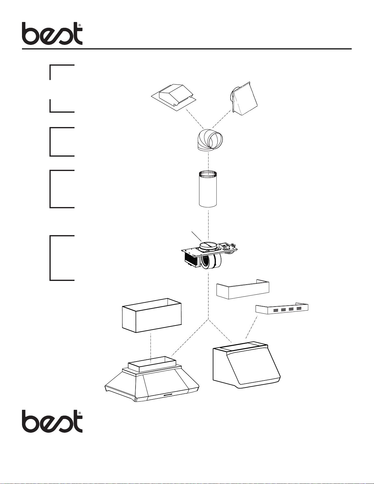
Wall & Roof Caps,
Exterior Blowers
Elbows
Ductwork
Blower
System
MODEL 634 OR 644
(roof cap)
MODEL 432
(8” round adjustable elbow)
MODEL 408
(8” round duct)
(8” Damper - included)
MODEL 643
(8’’ Round wall cap)
MODEL iQ6
BLOWER/ROUGH-IN KIT
(600 cfm interior blower
& rough-in plate)
OPTIONAL
DECORATIVE
FLUE
IP29M
SERIES HOOD
(Canopy with
blower controls
& lighting.)
INTERNAL BLOWER
RANGE HOOD SYSTEM
OPTIONAL
DECORATIVE FLUE
NON-DUCT KIT FLUE
ANKWP & ANKUP SERIES
(for WP28M & WP29M
Series Hoods Only)
WP28M, WP29M,
UP26M, UP27M
SERIES HOODS
(Canopy with blower
controls & lighting.)
INSTALLATION
MODEL iQ6
Page 3
REMOVE ONE
ELECTRICAL
KNOCKOUT
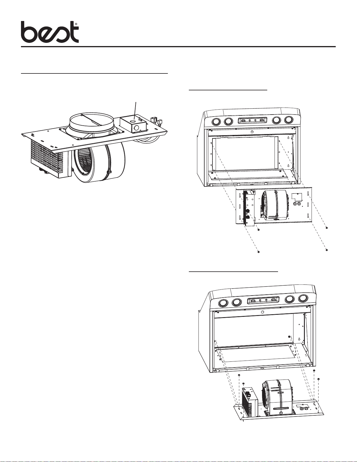
1. Run power cable to installation location.
2. Remove one electrical knockout from rough in plate wiring
box.
VERTICAL DISCHARGE
(UP26M, UP27M, WP28M, WP29M, IP29M)
HORIZONTAL DISCHARGE
(WP28, WP29)
3. Attach rough in plate to mounting studs at inside of hood
with (4) existing 10-32 Hex Nuts.
ROUGH-IN PLATE
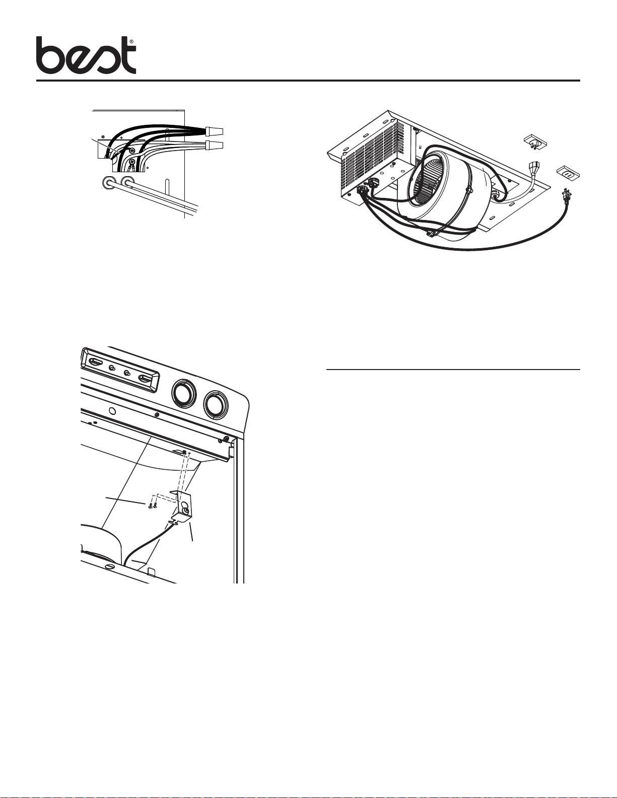
GROUND WIRE
TO GROUND
SCREW
4. Remove wiring cover.
5. Connect power cable to wiring box using proper connector.
Connect Black to Black (hot), White to White (neutral) and
Green or Bare wire (ground) under second ground screw.
Replace wiring cover.
6. Run 8” round steel duct to installation location.
7. Connect duct to damper. Seal using duct tape to make all
joints secure and air tight.
BLACK TO BLACK
WHITE TO WHITE
MODEL iQ6
Page 4
9. Plug blower power cord and rough in plate power cord into
hood receptacles
10. Wrap excess wires with wire ties (provided) to prevent
contact with blower wheel.
CALIBRATE iQ BLOWER
SYSTEM
(2) SCREWS
CALIBRATION
BUTTON
ASSEMBLY
8. Install the calibration button assembly using (2) screws
(provided).
Ducted Internal Blower Hoods Only
After the blower is installed in the and wired, engage the
calibration process (our Guaranteed Performance System
Technology) to ensure full-rated airflow is being delivered.
Prior to calibration, ensure that all light bulbs and duct system
components are installed and sealed.
CALIBRATION PROCESS
Hold the calibration button for 3 seconds; calibration button will
light up and stay on for up to 13 minutes. Install filters and wait for
blower to start which signals the start of the calibration process.
When calibration is complete, one of two things will occur:
A. The blower turns off and calibration button light turns off =
Successful calibration.
B. The blower turns off and calibration button light blinks
continuously = Too much restriction in the ductwork is
preventing the IQ Blower SystemTM from achieving the rated
airflow. The blower is automatically set to maximum intensity.
NOTE: Common items that cause restrictions: restricted damper
flap (backdraft damper, wall cap, roof cap), too many elbows,
duct size less than 80% of hood outlet, poor transition, use of flex
ducting and/or crushed ducting.
Two options are available:
1. Press the calibration button to accept airflow as is. The IQ
Blower SystemTM is now configured to its highest possible
setting. The blinking calibration light goes out.
2. Correct duct restriction and repeat the calibration process.
a. To clear the original calibration data, hold calibration
button for 10 seconds. The light will blink 3 times to
confirm and the blower configuration will go back to
default settings.
b. Repeat calibration process.

SERVICE PARTS
Model iQ6
MODEL iQ6
Page 5
KEY PART DESCRIPTION QTY
NO. NUMBER
1 97019389 ROUGH IN PLATE WELDMENT 1
2 98003370 OUTLET BOX COVER 1
3 99440033 POWER CORD 1
4 99150471 SCREW, #10-32 X 1/2 HEX
WASHER HEAD 2
5 99271500 BOARD POWER WIRE HARNESS 1
6 99400060 STRAIN RELIEF 2
7 99170245 SCREW, #8-18X3/8” 5
8 SV08543 8” DAMPER 1
# 97019456 ROUGH IN KIT (COMPLETE)
(INCLUDES KEYS 1-7)
9 PCB ENCLOSURE RIGHT 1
10 PCB ENCLOSURE LEFT 1
11 99170245 SCREW, #8-18X3/8” 5
# 97019457 PCB ENCLOSURE KIT
(INCLUDES KEYS 9-11)
12 SCREW, 3MM X 6MM PH
W/LOCK WASHER 5
13 IQ6 PCB BOARD 1
# 97019458 IQ6 PCB BOARD KIT
(INCLUDES KEY 12 AND KEY 13)
14 PCB TRIAC BOARD 1
15 STANDOFF 4
# 97019471 PCB TRIAC BOARD KIT
(INCLUDES KEY 14 AND 15)
16 99400088 STRAIN RELIEF 2
17 97018985 BLDC BLOWER 1
+ 99271491 SPEED CONTROL WIRE HARNESS 1
+ 99271503 CALIBRATION BUTTON
WIRE HARNESS 1
+ 99260488 NUT WHIZ 10-24 6
7
1
8
2
6
7
3
4
9
13
14
5
11
15
10
12
+ NOT SHOWN
# NOT SHOWN ASSEMBLED
* STANDARD HARDWARE. MAY BE PURCHASED LOCALLY.
16
11
17
 Loading...