

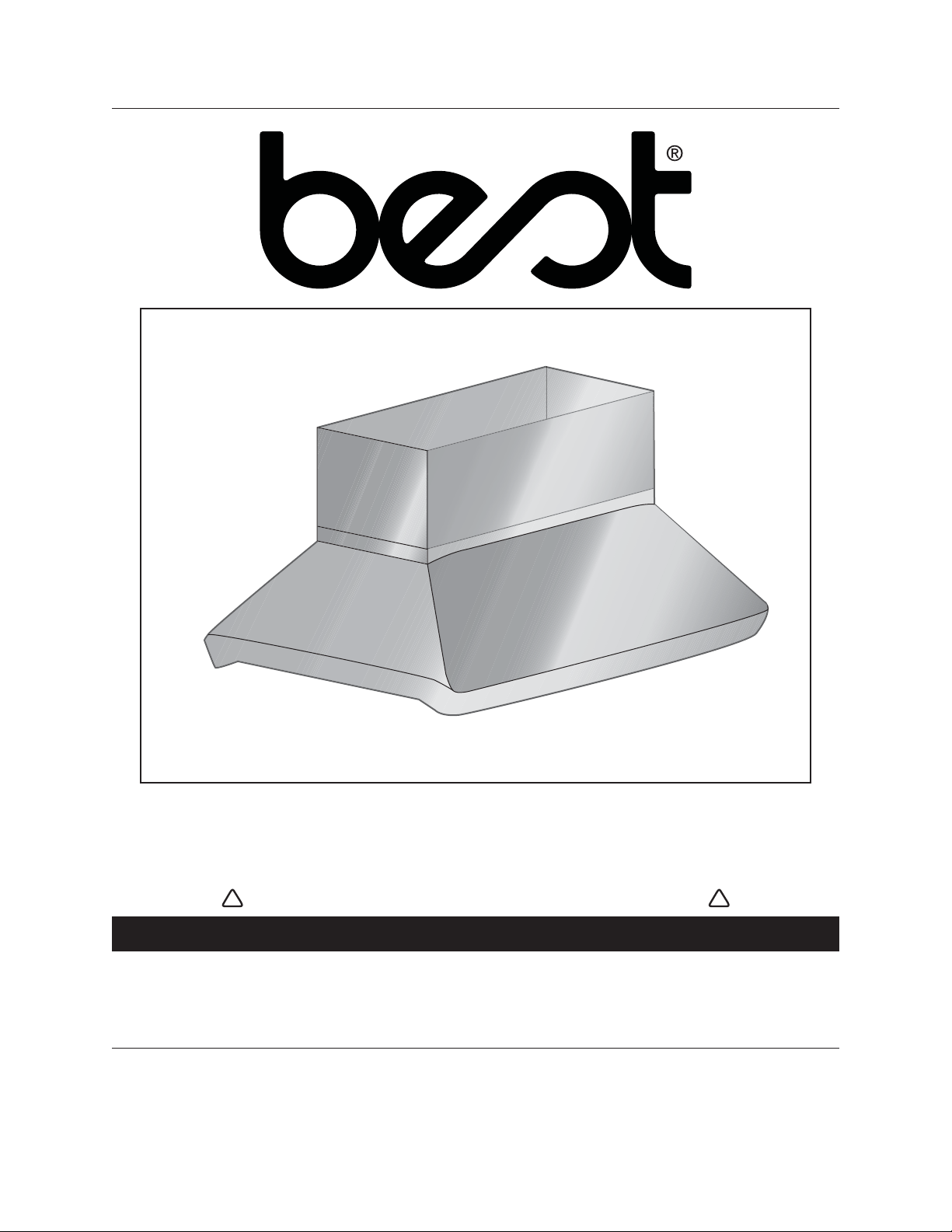
IP29M SERIES
INTENDED FOR DOMESTIC COOKING ONLY
INSTALLER: LEAVE THIS MANUAL WITH HOMEOWNER.
HOMEOWNER: USE AND CARE AND OPERATION INFORMATION
ON PAGES 12 TO 15.
SV08072 rev. I
INSTALLATION INSTRUCTIONS
READ AND SAVE THESE INSTRUCTIONS
!
!
BEST; Hartford, Wisconsin www.BestRangeHoods.com 800-558-1711
BEST; Drummondville, QC, Canada www.BestRangeHoods.com 866-737-7770
REGISTER YOUR PRODUCT ON LINE AT: www.BestRangeHoods.com/register
HB0063

WARNING WARNING
- 2 -
TO REDUCE THE RISK OF FIRE, ELECTRIC
SHOCK OR INJURY TO PERSONS, OBSERVE
THE FOLLOWING:
1. Use this unit only in the manner intended by the
manufacturer. If you have questions, contact the
manufacturer at the address or telephone number
listed in the warranty.
2. Before servicing or cleaning unit, switch power
off at service panel and lock service disconnecting
means to prevent power from being switched on
accidentally. When the service disconnecting
means cannot be locked, securely fasten a prominent
warning device, such as a tag, to the service panel.
3. Installation work and electrical wiring must be
done by qualified personnel in accordance with all
applicable codes and standards, including fire-rated
construction codes and standards.
4. Sufficient air is needed for proper combustion and
exhausting of gases through the flue (chimney) of
fuel burning equipment to prevent backdrafting.
Follow the heating equipment manufacturer’s
guidelines and safety standards such as those
published by the National Fire Protection
Association (NFPA), and the American Society for
Heating, Refrigeration and Air Conditioning
Engineers (ASHRAE), and the local code authorities.
5. When cutting or drilling into wall or ceiling, do not
damage electrical wiring and other hidden utilities.
6. Ducted fans must always be vented to the outdoors.
7. Do not use this unit with any additional solid-state
speed control device.
8. To reduce the risk of fire, use only steel ductwork.
9. This unit must be grounded.
10. When applicable local regulations comprise
more restrictive installation and/or certification
requirements, the aforementioned requirements
prevail on those of this document and the installer
agrees to conform to these at his own expenses.
TO REDUCE THE RISK OF A RANGE TOP GREASE
FIRE:
a) Never leave surface units unattended at high
settings. Boilovers cause smoking and greasy
spillovers that may ignite. Heat oils slowly on low or
medium settings.
b) Always turn hood ON when cooking at high heat or
when flambeing food (i.e.: Crêpes Suzette,
Cherries Jubilee, Peppercorn Beef Flambé).
c) Clean ventilating fans frequently. Grease should
not be allowed to accumulate on fan or filter.
d) Use proper pan size. Always use cookware appropriate
for the size of the surface element.
TO REDUCE THE RISK OF INJURY TO PERSONS
IN THE EVENT OF A RANGE TOP GREASE
FIRE, OBSERVE THE FOLLOWING*:
1. SMOTHER FLAMES with a close-fitting lid, cookie
sheet or metal tray, then turn off the burner.
BE CAREFUL TO PREVENT BURNS. IF THE
FLAMES DO NOT GO OUT IMMEDIATELY,
EVACUATE AND CALL THE FIRE DEPARTMENT.
2. NEVER PICK UP A FLAMING PAN—You may be
burned.
3. DO NOT USE WATER, including wet dishcloths or
towels—This could cause a violent steam explosion.
4. Use an extinguisher ONLY if:
A. You own a Class ABC extinguisher and you
know how to operate it.
B. The fire is small and contained in the area
where it started.
C. The fire department has been called.
D. You can fight the fire with your back to an exit.
* Based on “Kitchen Fire Safety Tips” published by NFPA.
CAUTION
!
!
1. For indoor use only.
2. For general ventilating use only. Do not use to exhaust
hazardous or explosive materials and vapors.
3. To avoid motor bearing damage and noisy and/or
unbalanced impellers, keep drywall spray,
construction dust, etc. off power unit.
4. Your hood motor has a thermal overload which will
automatically shut off the motor if it becomes
overheated. The motor will restart when it will be
cooled down. If the motor continues to shut off and
restart, have the hood serviced.
5. For best capture of cooking impurities, the bottom
of the hood should be at a minimum of 30” and at
a maximum of 36” above the cooking surface.
6. Two installers are recommended because of the
large size and weight of this hood.
7. To reduce the risk of fire and to properly exhaust
air, be sure to duct air outside—Do not exhaust air
into spaces within walls or ceiling or into attics,
crawl space or garage.
8. This product is equipped with a thermostat which
may start blower automatically. To reduce the risk
of injury and to prevent power from being switched
on accidentally, switch power off at service panel
and lock or tag service panel.
9. Because of the high exhausting capacity of this
hood, you should make sure enough air is entering
the house to replace exhausted air. Use an appropriate
make-up air device or open a window close to or in
the kitchen.
10. To reduce the risk of fire and electric shock, the
Best IP29M Series hood must be installed with
Best interior blower models
P6 or P12; Best exterior
blower models
EB6, EB9, EB12 or EB15; Best
in-line blowers models ILB3, ILB6, ILB9, ILB11.
Other blowers cannot be substituted. (Blowers sold
separately.)
11. Please read specification label on product for
further information and requirements.
- 3 -
Model 415
(7” round adjustable elbow)
Model 427
(4½” x 18½”
to 10” Round,
6” high - lateral
Model 423
(4½” x 18½” to
10” Round - vertical
Model 424
(4½” x 18½” to
10” Round - horiz.
front/rear
Model 454
(4½” x 18½”
to 10” Round -
horiz. /right
Model 453
(4½” x 18½”
to 10” Round -
horiz. /left
IP29M SERIES
HOOD
(Canopy with
blower controls
& lighting.
Required for all
installations.)
OPTIONAL
DECORATIVE FLUE
AEIP SERIES
OPTIONAL
DRYWALL TRIM
ATDIP SERIES
- IP29M SERIES RANGE HOOD SYSTEM -
INTERIOR BLOWERS
Model 437
(High capacity roof cap)
Model 441
(10’’ Round wall cap)
Model 634 or 644
(roof cap)
Model 647
(7” Round wall cap)
Model 407
(7” round duct—2 ft. sections)
Model 410
(10” round duct—2 ft. sections)
MODEL P6
BLOWER/ROUGH-IN KIT
(600 cfm interior blower &
rough-in plate)
MODEL P12
BLOWER/ROUGH-IN KIT
(1200 cfm interior blower
& rough-in plate)
Model 418
(10” round adjustable elbow)
Model 421
(10” Round Vertical
In-line damper —
Optional)
HL0091
- 4 -
- IP29M SERIES RANGE HOOD SYSTEM -
IN-LINE AND EXTERIOR BLOWERS
In-line and exterior blower rough-in kit
(included with EB6, EB9, EB12, EB15,
ILB3, ILB6, ILB9 and ILB11 blowers.)
Model 418
10” Round
adjustable elbow
(optional)
Model ILB3 (280 cfm)
in-line blower
(includes one 8” to 10”
round transition)
Model EB6 (600 cfm)
or EB9(900 cfm)
exterior blower
Model EB12 (1200 cfm)
or EB15 (1500 cfm)
exterior blower
Model 441
(10” Round
wall cap)
Model 437
(High capacity roof cap)
Model 441
(10” Round wall cap)
Model 421
(10” Round vert.
in-line damper)
Recommended
for use with
exterior blowers
Model 410
(10” Round duct
—2ft. sections)
Model ILB6 (600 cfm)
in-line blower
(includes two 4½” x 18½”
to 10’’ round transitions)
Model ILB9 (800 cfm)
or ILB11 (1100 cfm)
in-line blower
(includes two 8” x 12” to
10’’ round transitions)
IP29M SERIES
HOOD
(Canopy with
blower controls
& lighting.
required for all
installations.)
OPTIONAL
DECORATIVE FLUE
AEIP SERIES
OPTIONAL
DRYWALL TRIM
ATDIP SERIES
Model 643
(8” Round
wall cap)
HL0090
- 5 -
1. SELECT BLOWER OPTION AND INSTALLATION TYPE
Either an interior or an exterior blower or in-line blower may be used with this hood. The Best IP29M Series must be installed with
blower models P6, P12, ILB3, ILB6, ILB9, ILB11, EB6, EB9, EB12 or EB15 only. Other blowers cannot be substituted. (Blowers
sold separately.)
Plan where and how the ductwork will be installed.
If installing in-line blower, refer to instructions packed with in-line blower and follow steps 1 up to 9, 11 to 15, 17 and up of
this manual.
Install proper-sized ductwork, elbows and roof or wall cap for the type of blower you are installing. Use metal duct tape to seal duct joints.
7” (178) ROUND DUCT
ROOF CAP
30” TO 36” (762 to 914)
ABOVE COOKING SURFACE
HOOD
DECORATIVE
FLUE
12”, 18”, 24” or 30”
(305, 457, 610 or 762)
or TRIM
HH0080A
NOTE: Dimensions in ( ) are in mm.
MODEL P6 SINGLE INTERIOR BLOWER
TYPICAL DUCTWORK
10” (254) ROUND DUCT
ROOF CAP
30” TO 36” (762 to 914)
ABOVE COOKING SURFACE
HOOD
DECORATIVE
FLUE
12”, 18”, 24” or 30”
(305, 457, 610 or 762)
or TRIM
HH0081A
NOTE: Dimensions in ( ) are in mm.
ROUND
TRANSITION
4½” x 18½”
to 10”
(114 x 470
to 254)
(see page 3)
MODEL P12 DUAL INTERIOR BLOWER
TYPICAL DUCTWORK
10” (254)
ROUND DUCT
EXTERIOR
BLOWER
30” TO 36” (762 to 914)
ABOVE COOKING SURFACE
HOOD
DECORATIVE
FLUE
12”, 18”, 24” or 30”
(305, 457, 610 or 762)
or TRIM
HH0082A
NOTE: Dimensions in ( ) are in mm
MODEL EB6, EB9, EB12 OR EB15
EXTERIOR BLOWER TYPICAL DUCTWORK
IN-LINE BLOWER
HH0083A
30” TO 36 ” [762 to 914]
ABOVE COOKING SURFACE
ROOF CAP
WALL
CAP
HOOD
NOTE: Dimensions in [ ] are in mm.
DECORATIVE
FLUE
12”, 18”, 24” or 30”
[305, 457, 610 or 762]
or TRIM
10” [254] ROUND DUCT
(except ILB3, 8’’ [203] ROUND DUCT)
MODEL ILB3, ILB6, ILB9 OR ILB11
IN-LINE BLOWER TYPICAL DUCTWORK
Remove the installation kit from inside the hood.
Make sure that the following items are included:
- Installation manual
- Accessories including:
• 3 Evolution™ hybrid baffle filters
• Shielded halogen lights (GU10 type base, 120 V, 50 W) (6 for 42” width hoods, 8 for 54” width hoods)
• Bag of parts including:
(10) steel wood screws no. 10 x 1.5’’, (10) steel washer no. 10, (6) screws no. 8 x 3/8’’ (additional screws provided)
Parts sold separately:
- Interior blower Model P6 (includes rough-in kit).
- Interior blower Model P12 (includes rough-in kit).
- In-line blower assembly ILB3, ILB6, ILB9 or ILB11 (all include transition and rough-in plate)
- Exterior blower assembly EB6, EB9, EB12 or EB15 (all include rough-in plate).
- Transitions, duct, elbows, dampers, wall and roof caps. Refer to pages 3 and 4 for a complete list of venting options and model numbers.
- Optional decorative flue cover AEIP Series, 12’’, 18”, 24” or 30” height and 42” or 54” width.
- Optional dry wall trim ATDIP Series, 42” or 54” width.
- 6 -
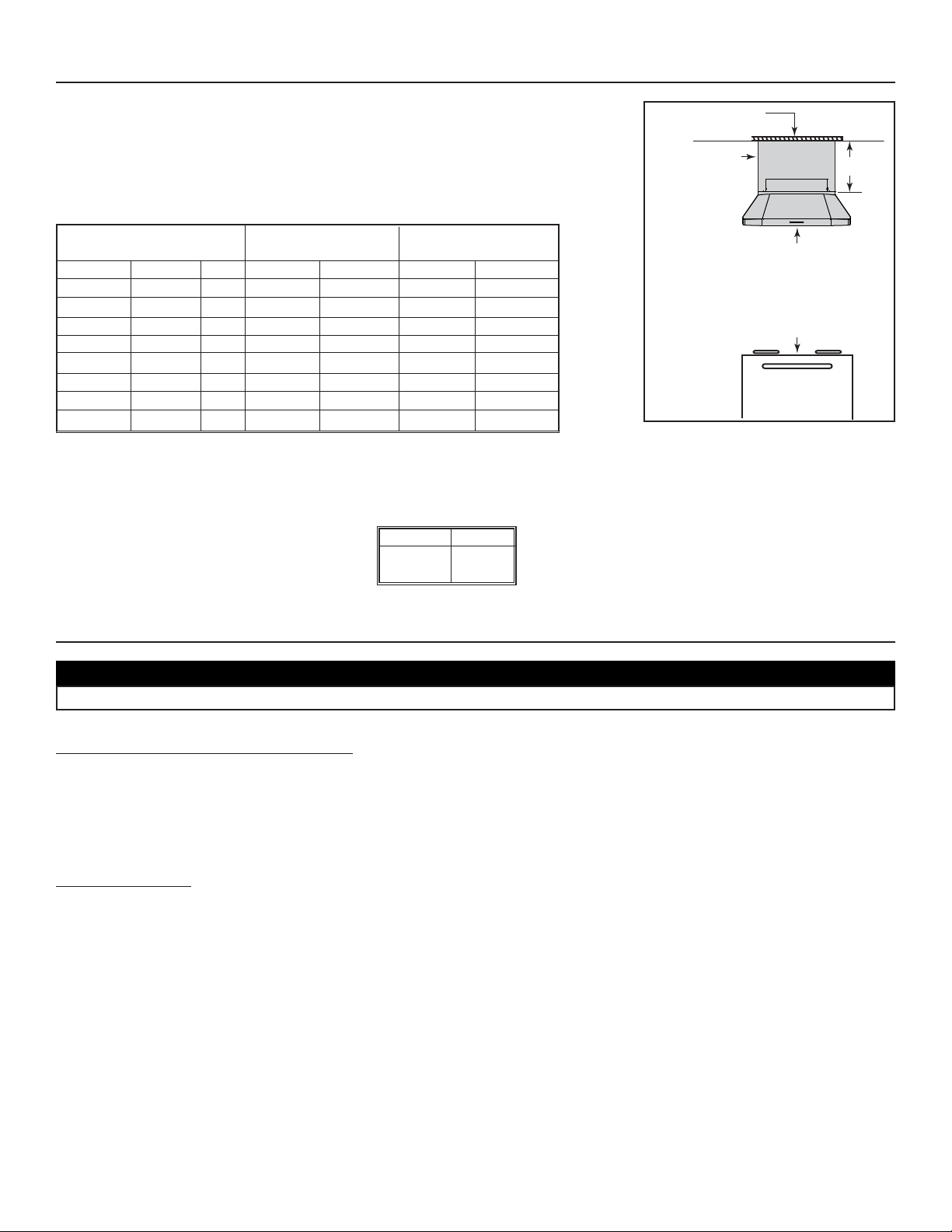
3. PREPARE THE INSTALLATION
2. MEASURE INSTALLATION
Dimensions for the most common installation are shown beside.
The minimum hood distance above cooktop must not be less than 30’’. A maximum of
36” above cooktop is highly recommended for best capture of cooking impurities.
Distances over 36” are at the installer and users discretion.
Since framework must be flush to ceiling, 4 decorative flue covers have been created to fit
both hood widths and different ceiling heights. Refer to table below to choose the model that
fits your needs.
If a drywall box will be built instead of installing decorative flue cover, use drywall trim to hide hood and drywall junction. Refer to table
below to find the appropriate model for your hood width.
L
INKLOGIC® ENABLED HOOD
This hood includes the LinkLogic system which allows communication over ordinary household electrical wiring to other LinkLogic
devices including the Broan Smart Sense Fan system. If you intend to use this hood with another LinkLogic device, follow the instructions
found in section 21 along with the instructions that come with the LinkLogic device you plan to use.
MINIMUM AND MAXIMUM DISTANCE
OVER COOKTOP
CAUTION
When performing installation, servicing or cleaning the unit, it is recommended to wear safety glasses and gloves.
DECORATIVE FLUE COVER
8’ CEILING 9’ CEILING
DISTANCE FROM COOKTOP DISTANCE FROM COOKTOP
MODEL A (HEIGHT)WIDTH 30” 36” 30” 36”
AEIP422 12” 42” X
AEIP542 12” 54” X
AEIP428 18” 42” X
AEIP548 18” 54” X
AEIP424 24” 42” X
AEIP544 24” 54” X
AEIP420 30” 42” X
AEIP540 30” 54” X
MODEL WIDTH
ATDIP42 42”
ATDIP54 54”
NOTE: For ceilings over 9’, decorative flues are not available.
Framework
flush to ceiling
Decorative flue
cover or drywall
with trim
A
Minimum distance between
the hood and cooktop:
30’’ (762 mm)
Recommended maximum
distance between the hood
and cooktop: 36’’ (914 mm)
HH0084A
Standard 36”
(914 mm)
high cooktop
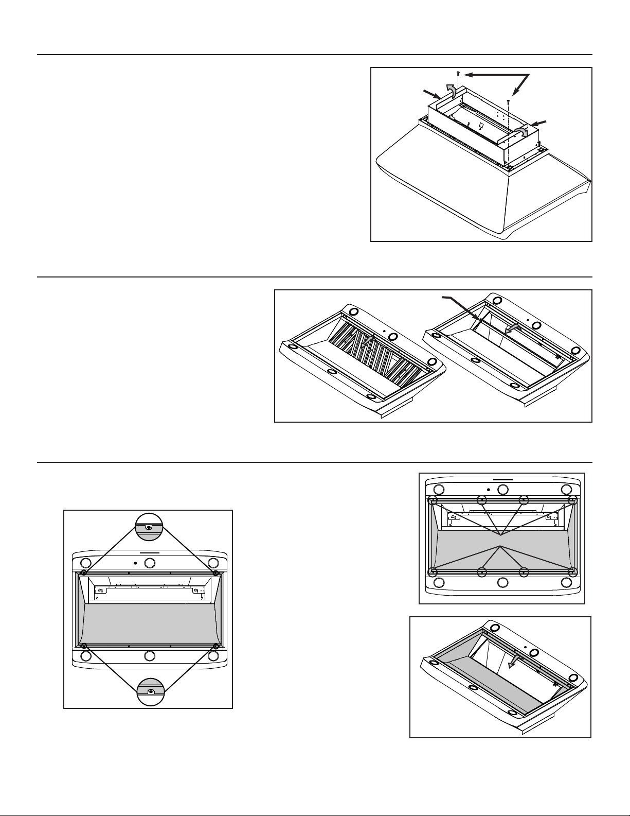
Using a Phillips no. 2, remove 8 screws
retaining the pan (shaded part on
illustration beside) to the hood.
Remove the pan and set aside.
- 7 -
5. REMOVE THE FILTERS AND THE GREASE DRIP RAIL
A. Remove tape on filters. Remove filters from hood and
set aside.
NOTE: It is recommended to start with the central one.
B. Remove tape on grease drip rail (1).
Lift out grease drip rail and set aside.
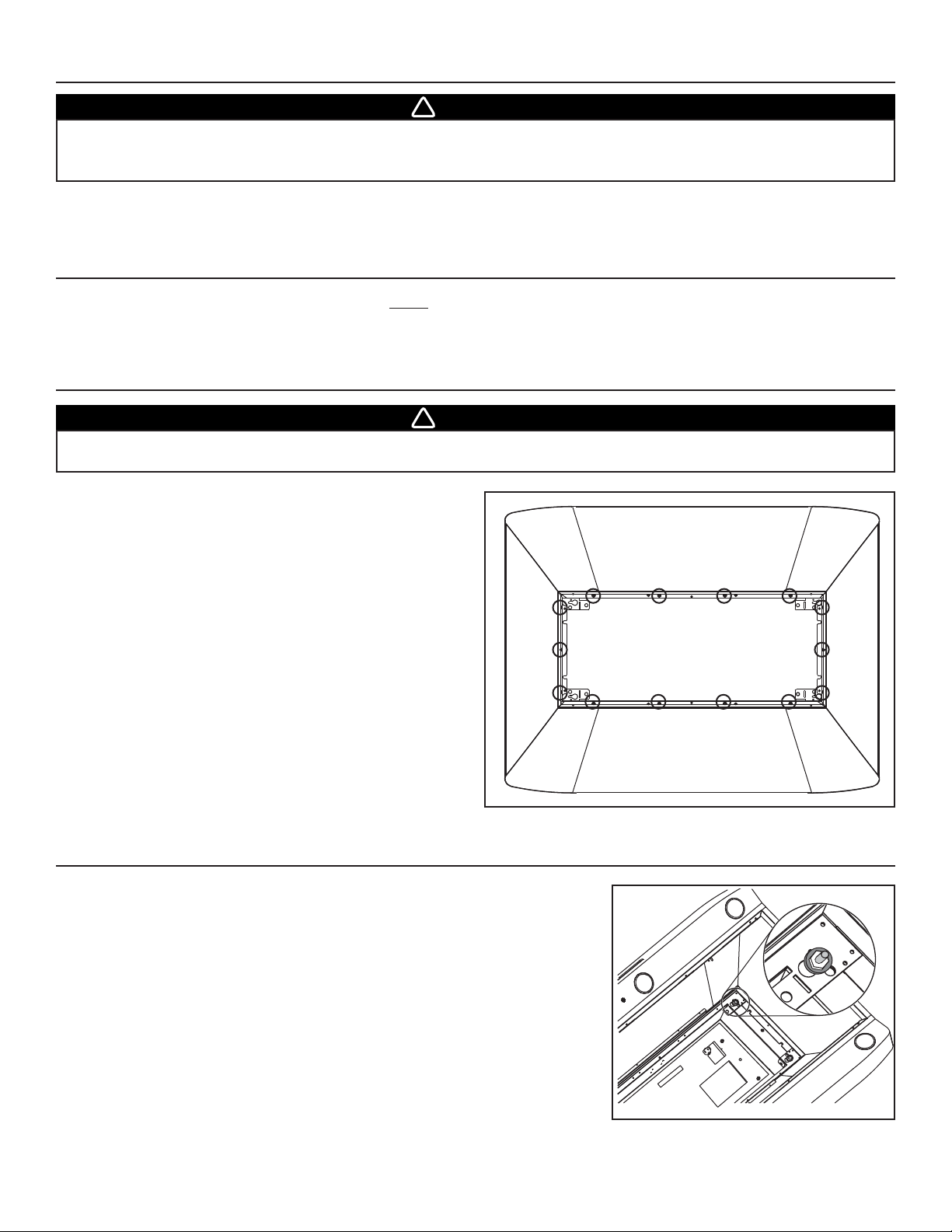
6. REMOVE THE PAN
NOTE: Do not remove the 4 screws located on the
notched parts of the pan (A on figure below).
1
A
A
4. PREPARE THE BLOWER HOUSING
Detach the blower housing from the hood by removing its both retaining screws (A).
Keep the screws for further use.
Fold up its both flanges (B). The flanges must be perpendicular to the top of the
blower housing.
A
B
B
RETAINING SCREWS LOCATION
HD0229
HD0222
HD0224
HD0223
HD0238
- 8 -
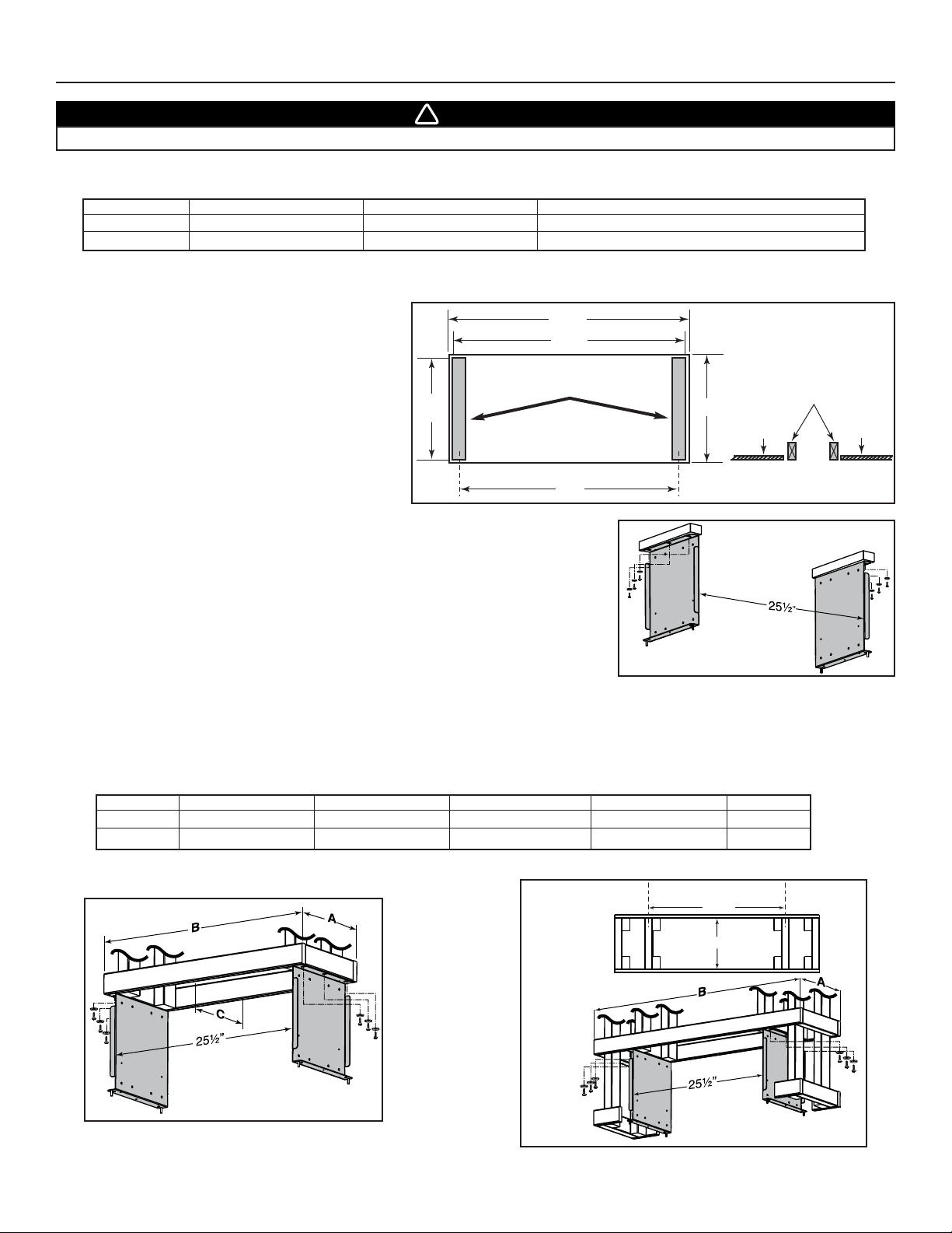
In the ceiling material, cut-out a 28¾” x 12½” max.
opening over the installation location. Install two
supporting studs inside the cut-out at dimensions
shown beside.
7. BUILD THE FRAMEWORK
7.1 SUGGESTED FRAMEWORK FOR INSTALLATION WITH DECORATIVE FLUE COVER AEIP SERIES
7.2 SUGGESTED FRAMEWORK FOR INSTALLATION WITH DRYWALL TRIM ATDIP SERIES
FRAMEWORK 54’’ HOOD
FRAMEWORK 42’’ HOOD
WARNING
When building framework, always follow all applicable construction codes and standards.
!
The framework must be sized to support the total weight of the hood. Refer to the table below for total weight of the hood, according to the
type of blower chosen.
HOOD WIDTH WITH P6 INTERIOR BLOWER WITH P12 INTERIOR BLOWER WITH IN-LINE OR EXT. BLOWER (ROUGH-IN PLATE ONLY)
42” 71 LB 84 LB 52 LB
54” 86 LB 99 LB 67 LB
SUPPORTING STUDS
Using provided wood screws no. 10 x 1.5” and washers, assemble both mounting brackets
(included with the optional decorative flue cover) to the framework. See illustration beside.
Below is the suggested framework for both 42” and 54” width hoods to be installed with drywall trim ATDIP Series. Refer to the table and
illustrations below for the dimensions according to the hood width. Using provided wood screws no. 10 x 1.5” and washers, assemble
both mounting brackets (included with the optional drywall trim) to the framework.
HOOD WIDTH A WITH 5/8” DRYWALL A WITH 1/2” DRYWALL B WITH 5/8” DRYWALL B WITH 1/2” DRYWALL C
42” 11
5
⁄8”11
7
⁄8”28
5
⁄8”28
7
⁄8” 10” MINIMUM
54” 115⁄8”11
7
⁄8”40
5
⁄8”40
7
⁄8” 10” MINIMUM
FRAMEWORK
TOP VIEW
28¾”
28½”
12½”
max.
12 /
5
8”
Studs flush
with ceiling material
Ceiling
material
Ceiling
material
C
L
HD0227A
C
L
27”
HD0228A
C
L
27¼”
C
C
L
HD0235A
HD0237A
- 9 -
INSTALLATION WITH
DRY WALL TRIM ATDIP SERIES
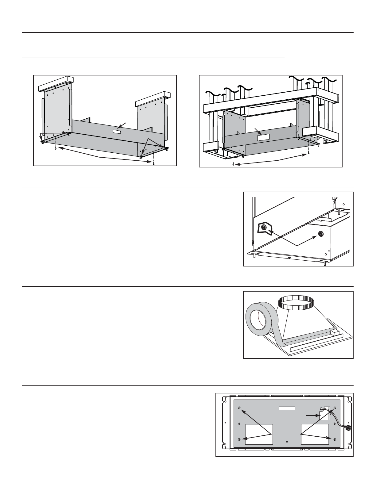
8. INSTALL BLOWER HOUSING
Use both screws (A) previously removed in step 4 to assemble the blower housing to the mounting brackets. For installation with decorative
flue cover AEIP Series only, place 4 nuts (B) (from flue cover parts bag) on the pem studs, leaving 1/4” for the hood installation. The blower
housing must be installed in such a way that its label (C) will be on the same side as the hood control side. See illustrations below.
INSTALLATION WITH
DECORATIVE FLUE COVER AEIP SERIES
A
B
B
Model 423, 424, 427 453, or 454
Attach transition (if required) to blower rough-in plate.
Use metal duct tape to make all joints secure and air-tight.
NOTE: Model P6 blower plate connects directly to 7’’ round ductwork without a transition.
10. INSTALL TRANSITION TO ROUGH-IN PLATE (INTERIOR BLOWER ONLY)
11. INSTALL THE ROUGH-IN PLATE IN THE BLOWER HOUSING
Run power cable to installation location. Refer to the instructions included with
the selected blower/rough-in kit (sold separately) for details on installing the
rough-in plate. Install the rough-in plate so that the wiring box is located on the
right side when facing the hood, as specified on the blower housing label.
Connect transition or rough-in plate to ductwork. Use metal duct tape to make
all joints secure and air-tight.
C
C
WIRING COVER
LOCK NUTS
A
From the inside, secure the blower housing to mounting brackets, using 2 no. 8 x 3/8”
screws per side.
Screws must be installed in embossed sections, see details beside.
9. SECURE BLOWER HOUSING TO BRACKETS
RETAINING SCREWS LOCATION
HD0230
HD0231
HO0100
HO0086
HD0232
- 10 -
15. INSTALL THE HOOD
15.1INSTALLATION WITH DECORATIVE FLUE COVER AEIP SERIES
Assemble the hood assembly to the mounting brackets by aligning keyholes with
4 nuts previously installed in step 8 (2 nuts per side). While holding the hood,
remove one nut and install a washer (included in parts bag) on each pem
stud, then reinstall the nut and tighten it. See illustration beside.
15.2INSTALLATION WITH DRY WALL TRIM ATDIP SERIES
Align hood keyholes with pem studs on brackets. Secure the hood to the brackets
using washers and nuts (included in parts bag). See illustration beside.
14. MOUNT THE DECORATIVE FLUE COVER OR THE DRY WALL TRIM ON THE HOOD
14.1INSTALLATION WITH DECORATIVE FLUE COVER
AEIP SERIES
Remove the protective plastic film covering the decorative flue
cover AEWP Series. Assemble the flue cover on top of hood
using (14) no. 8 x 3/8” screws (provided with decorative flue
cover). See illustration beside to locate mounting screws from
top of hood.
NOTE: Ensure edges fit perfectly before tightening completely
the mounting screws.
14.2INSTALLATION WITH DRY WALL TRIM ATDIP SERIES
Remove the protective plastic film covering the dry wall trim
ATDPI Series. Assemble the dry wall trim on the top of the
hood using (14) no. 8 x 3/8” screws (provided with dry wall
trim). See illustration beside to locate mounting screws from
top of hood.
NOTE: Ensure edges fit perfectly before tightening completely
the mounting screws.
WARNING
The decorative flue cover AEIP Series and the dry wall trim ATDIP Series may have sharp edges. Be careful when
handling and installing these metal parts.
!
MOUNTING SCREWS LOCATION
13. FINISH THE DRYWALL BOX (INSTALLATION WITH DRY WALL TRIM ATDIP SERIES ONLY)
Finish the drywall box. Check fitting with dry wall trim before mounting it to the hood.
12. CONNECT THE WIRING
Remove wiring cover from rough-in plate and set aside.
Connect BLACK to BLACK, WHITE to WHITE and GREEN or bare wire under GREEN ground screw. Reinstall wiring cover.
WARNING
Risk of electrical shock. Electrical wiring must be done by qualified personnel in accordance with all applicable
codes and standards. Before connecting wires, switch power off at service panel and lock service disconnecting
means to prevent power to be switched on accidentally.
!
HD0233
HD0234

17. REINSTALL THE PAN
Using a Phillips no. 2 or Robertson no. 2 screwdriver and the retaining screws, reinstall the pan
(previously removed in step 6) inside the hood (shaded part on illustration beside).
RETAINING SCREWS LOCATION
Reinstall grease drip rail (1). The illustration beside shows how to reinsert the
grease drip rail(s) into the range hood.
18. REINSTALL GREASE DRIP RAIL AND BAFFLE FILTERS
Reinstall Evolution™ hybrid baffle filters on
the hood.
It is recommended to install side filters first
and finish with center one.
1. Insert one end of Evolution™ hybrid baffle
filter into the front channel of the hood.
2. Raise the other end toward the inside of
hood and insert in the grease drip rail of
the hood.
Replacement filters are available from your
dealer. See label inside hood for size and
part number.
CAUTION
Remove protective plastic film covering Evolution™ hybrid baffle filters before installing them.
1
- 11 -
16. INSTALL THE BLOWER (INTERIOR OR EXTERIOR BLOWER)
Refer to instructions included with blower.
Once the blower is installed, plug the blower cord (A) into the female receptacle and the
power supply cord (B) onto the male connector inside the hood.
HE0078
WARNING
Do not plug the two cords into each other.
!
AB
CAUTION
Remove protective plastic film covering pan sides and tape over halogen lamps.
HD0224
HD0225
HD0226
12
- 12 -
20. USE AND CARE
Evolution™ Hybrid Baffle Filters
The Evolution™ hybrid baffle filters should be cleaned frequently. Use a warm detergent solution. Wash more often if your cooking style
generates greater grease—like frying foods or wok cooking.
Remove Evolution™ hybrid baffle filters by pushing them towards the back of hood and rotating filters downward. Slide out the
secondary micromesh filter from the back of each hybrid baffle filter before cleaning. Baffle filters are dishwasher safe. Clean secondary
filters with a warm detergent solution. Allow filters to dry completely before reinstalling them in the hood.
Clean all-metal filters in the dishwasher using a non-phosphate detergent. Discoloration of the filter may occur if using phosphate detergent
or as a result of local water conditions—but this will not affect filter performance. This discoloration is not covered by the warranty.
Grease Drip Rail
The grease drip rail should be cleaned frequently. Lift it out from the hood and use a warm detergent solution. As for the baffle filters,
wash more often if your cooking style generates greater grease—like frying foods or wok cooking. Allow grease drip rail to dry completely
before reinstalling it in the hood.
Blower Cleaning
Remove the filters in order to access the blower. Vacuum blower to clean. Do not immerse in water. Refer to blower instruction manual
for more details.
Hood Cleaning
Stainless steel cleaning: How to maintain its “BRIGHT LOOK”
Do:
• Regularly wash with clean cloth or rag soaked with warm water and mild soap or liquid dish detergent.
• Always clean in the direction of original polish lines.
• Always rinse well with clear water (2 or 3 times) after cleaning. Wipe dry completely.
• You may also use a specialized household stainless steel cleaner.
Don’t:
• Use any steel or stainless steel wool or any other scrapers to remove stubborn dirt.
• Use any harsh or abrasive cleansers.
• Allow dirt to accumulate.
• Let plaster dust or any other construction residues reach the hood. During construction or renovation, cover the hood to make sure
no dust sticks to stainless steel surface.
Avoid: When choosing a detergent
• Any cleaners that contain bleach will attack stainless steel.
• Any products containing: chloride, fluoride, iodide, bromide will deteriorate surfaces rapidly.
• Any combustible products used for cleaning such as acetone, alcohol, ether, benzol, etc., are highly explosive and should never be
used close to a range.
19. LIGHT BULBS REPLACEMENT
This hood must use 120 V, 50 W, MR16 with GU10 base or PAR16 with GU10 base, shielded halogen lamps (included).
WARNING
In order to prevent the risk of personal injury, do not install a lamp identified for use only in enclosed fixtures.
!
WARNING
In order to prevent the risk of personal injury, the halogen lamps must be cooled down before removing them.
!
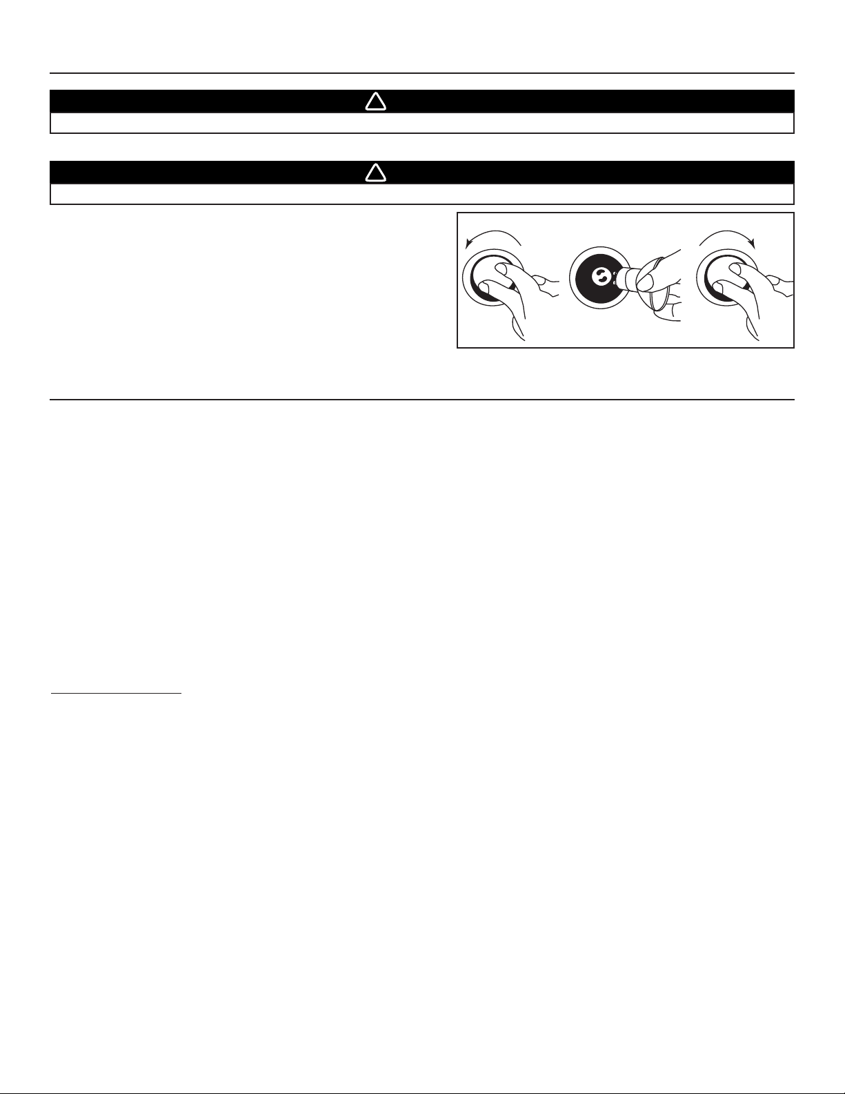
1. To remove lamps, gently push upwards and turn counterclockwise to
disengage bulb leads from their grooves.
NOTE: If need be, use a rubber dishwashing glove to add grip when
removing the bulb.
2. Install the new lamps by placing the bulb leads into their grooves in
the socket.
3. Gently push upwards and turn clockwise until secure.
12 3
HO0089

Always turn ON your hood before you begin cooking in order to establish an air flow in the kitchen. Let the blower run for a few minutes to
clear the air after you turn off the range. This will help keep the whole kitchen cleaner and brighter.
1. Halogen light push-button 6. Maximum blower speed icon
LinkLogic® Master Link Mode push-button 7. Particulates sensor icon
2. Blower push-button 8. Blower speed level/
3. Enable/Disable functions push-button/ LinkLogic® state icon
LinkLogic® Erase Link push-button 9. Air refresh function icon
4. Grease filter reset push-button/ 10. Blower speed icon
LinkLogic® Link Mode push-button 11. LinkLogic® icon
5. Grease filters maintenance icon
Cooktop Lighting (Halogen)
• The halogen lighting is controlled by the light push-button (item 1 on illustration above). Push once to turn ON the lights, and push a
second time to turn the lights ON to a brighter level. If the lights are at the highest level, pressing another time will set them to the
lowest intensity.
• Press on the push-button and maintain for 1 second to turn Off the lights and set the memorized intensity. When turned on, the
halogen bulbs will light cooktop at the previous setting.
• Use 120 V, 50 W, MR16 with GU10 base or PAR16 with GU10 base, shielded halogen lamps (included).
Blower
• The blower is controlled by the blower push-button (item 2 on illustration above). Push once to turn ON the blower, and push a
second time to set the blower speed to a higher level. If the blower speed is on maximum level, pressing another time will turn the
blower to the lowest speed.
• When power level 1 is activated from OFF, 100% of power level is activated during 0.3 second acting as a “kick-start”.
• Press on the push-button and maintain for 1 second to turn Off the blower and set the memorized speed. When turned ON, the
blower will operate at the previous setting.
• When the blower is ON, the speed level is shown by the center icon (item 8 on illustration above) while the icon 10 appears (the
speed of the rotational movement is proportional to the blower speed).
• When the blower is on the higher speed, the icon 10 shuts off and the icon 6 appears with “max” (the symbol has a rotational movement).
Functions
Pressing on Enable/Disable functions push-button (item 3 on illustration above) allows to control Particulate Sensor and Air Refresh
hood functions.
Particulates Sensor
• To activate the particulate sensor function, press on Enable/Disable functions push-button (item 3 on illustration above), the
particulates sensor icon (item 7 on illustration above) will appear.
• When the sensor is activated, the blower turns ON automatically when some particulates, vapors or smokes caused by cooking
process, or abnormal gas emissions in the environment are detected. The blower speed is automatically set depending on the
particulates amount and the sensibility settings of the particulates sensor. See next paragraph.
• To stop the particulates sensor function, press on Enable/Disable functions push-button until particulates sensor icon turns off.
Particulates sensor sensibility settings
• Press on Enable/Disable functions push-button (item 3 on illustration above) to activate the particulate sensor function, this will light
up the particulates sensor icon (item 7 on illustration above). Then, press and maintain for 2 seconds the Enable/Disable functions
push-button: the sensor sensivity level will appear on center icon (item 8 on illustration above).
• Press again on this push-button to change the sensor sensitivity level (from 0 [minimum sensitivity] up to 9 [maximum sensitivity]).
• Press on the grease filter reset push button (item 4 on the illustration above) to confirm (or is confirmed automatically after 5 seconds).
Air Refresh
• To activate the air refresh function, press on Enable/Disable functions push-button (item 3 on illustration above), the air refresh function
icon (item 9 on illustration above) will appear.
• To stop the air refresh function, press on Enable/Disable functions push-button until air refresh icon turns off.
• Air refresh function activates only when blower is OFF. When activated, the blower hood recycles the air in the environment in
perfect silence, starting every 50 minutes (for 10 minutes, on first speed).
Grease filter reset
• Once the grease filter cleaning is done, press on the grease filter reset push-button (item 4 on control illustration) to reset the filter
maintenance timer. This will also shut off the grease filter maintenance icon (item 5 on control illustration).
- 13 -
21. OPERATION
1
2 5 6 7 8 9 10 11 3 4
max
HC0032
S
O
N
R
E
S
AIR
REFRESH
- 14 -
Grease filter maintenance indicator
• After 30 hours of operation, the grease filter maintenance icon (item 5 on control illustration) appears. This means filters need to
be cleaned.
• Once the grease filter cleaning is done, press on grease filter reset push-button to reset the filter maintenance timer.
Interface backlighting
• Off mode (Blower off, Particulates sensor and Air refresh modes disabled): Backlighting is off.
• Halogen lighting activated: does not affect backlighting.
• Blower turns on: Backlighting at maximum intensity.
• Particulates sensor and Air refresh mode activated: Backlighting at maximum intensity.
• Particulates sensor at sensitivity settings and Air refresh in activated mode: Backlighting at minimum intensity.
HEAT SENTRY™
This hood is equipped with a HEAT SENTRY™ thermostat. This thermostat is a device that will start or speed up the blower if it senses
excessive heat above the cooking surface.
• If blower is OFF—it turns the blower to speed 3 (blower speed icon shows H).
• If blower is ON—it turns the blower up to speed 3 (blower speed icon shows H).
NOTE: When Heat Sentry™ is activated, Air refresh mode and Particulate sensor are inactivated. Also, communication coming
from the LinkLogic® Module is disabled.
• When the temperature level drops to normal, the blower will return to its original setting (blower speed icon will show the original
blower speed).
• To turn off the blower when Heat Sentry™ is activated, press and hold the blower push-button (item 2 on illustration) for more
than 1 second.
21. OPERATION (CONT’D)
LinkLogic® Network compatibility
Your IP29M Series range hood can be linked to LinkLogic network, if installed in your house.
LINKLOGIC LINKING INSTRUCTIONS
A. ACTIVATE THE “LINK” MODE OF THE HOOD
Push the LinkLogic link mode push-button (item 4 on control illustration) for 2 seconds; the LinkLogic icon of the interface (item 11 on
control illustration) should be visible and backlighting is full intensity at that point.
LINK OF ANOTHER LINKLOGIC DEVICE
Go back to the appropriate first step if another LinkLogic device
needs to be linked. Otherwise, to exit “link” mode, go to
E
XIT LINK MODE OF THE HOOD.
LINK FOR SMARTSENSE™ OR MAKE-UP AIR MODULES
STA RT T H E “MASTER LINK” PROCESS OF THE HOOD
Push the LinkLogic master link mode push-button
(item 1 on illustration) to start the “Master Link” process,
flashing “L” should be visible (item 8 on control illustration) on
the hood interface, meaning that the hood is waiting for a
SmartSense™ or Make-Up Air module to link.
ACTIVATE THE “LINK” MODE OF THE LINKLOGIC DEVICE
Push the “link” button of the LinkLogic device
(see instructions of device for location) for a specific duration to
activate its link mode. Wait for the “L” to disappear from the
hood interface to do next step.
STA RT T H E “AUTO-LINK” PROCESS OF THE HOOD
Push the LinkLogic link mode push-button
(item 4 on illustration) to start the “Auto-Link” process,
flashing “A” should be visible (item 8 on control illustration)
on the interface until link is done.
NOTE: For some LinkLogic devices, no “A” will be flashing
because the linking duration is too short.
ACTIVATE THE “LINK” MODE OF THE LINKLOGIC DEVICE
Push the “link” button of the LinkLogic device for
a specific duration to activate its link mode
(see instructions of LinkLogic device).
B. EXIT LINK MODE OF THE HOOD
Press and hold LinkLogic link mode push-button (item 4 on control illustration) for 2 seconds to exit “link” mode. Link mode remains
activated for 4 minutes if no other operation is done.
GOTOSTEP22 (ON NEXT PAGE) TO CONFIGURE LINKLOGIC
BOARD JUMPERS BASED ON BLOWER PERFORMANCE
.
LINK FOR WALL REMOTE CONTROL, REMOTE CONTROL
OR
REMOTE BLOWER MODULES
- 15 -
21. OPERATION (CONT’D)
ERASE LINK PROCESS
A. ACTIVATE THE “LINK” MODE OF THE HOOD
Push the LinkLogic link mode push-button (item 4 on control illustration) for 2 seconds; the LinkLogic icon of the interface (item 11
on control illustration) should be visible and backlighting is full intensity at that point.
B. ERASE ALL LINKED LINKLOGIC DEVICES
Push the LinkLogic erase link push-button (item 3 on control illustration) for 2 seconds to start the “Erase Link” process, flashing “E”
should be visible (item 8 on control illustration) on the hood interface until links are erased.
C. EXIT “LINK” MODE OF THE HOOD
Press and hold LinkLogic link mode push-button (item 4 on control illustration) for 2 seconds to exit “link” mode. Link mode remains
activated for 4 minutes if no other operation is done.
NOTE: If during normal operation of the range hood, the LinkLogic Icon (item 11 on control illustration) starts blinking, an error occurred
while communicating with a linked LinkLogic device. To reset this error flag, customer needs to enter and exit the Linking mode
as explained previously. This will erase the error flag until it happens again. If the problem happens again, it is recommended
to erase all links and start back the whole linking process.
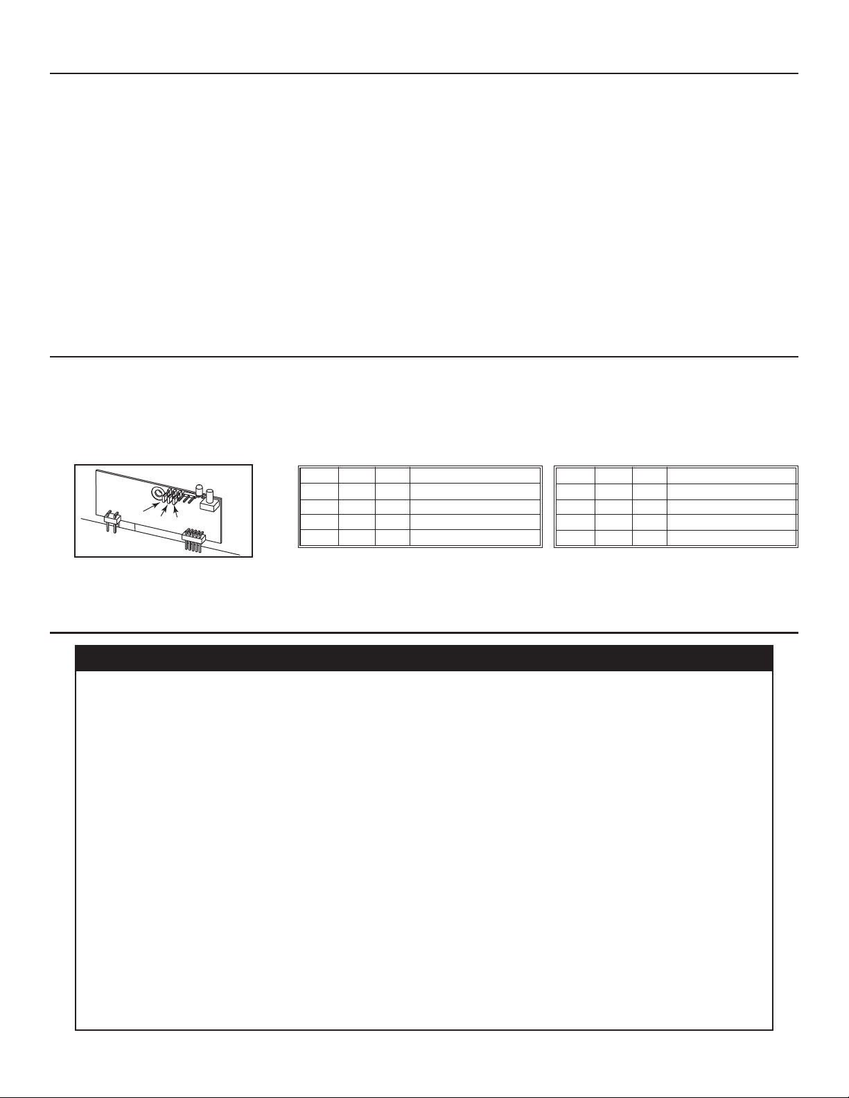
22. LINKLOGIC SYSTEM CONTROL BOARD JUMPERS
The LinkLogic system is designed to work with devices like the Broan Smart Sense Fan system that requires CFM output or this range
hood. If you are using this hood with a LinkLogic device that requires CFM information, please follow the simple instruction/matrix below
to configure the LinkLogic control board in the hood to provide the correct CFM information. To access the LinkLogic control board, remove
baffle filters, grease drip rail and hood pan (see steps 5 and 6). Remove both screws retaining the control panel to the hood. Rotate
carefully the control panel in order to see the LinkLogic board jumpers. Remove jumpers from current location on pins and reconfigure
based on blower performance.
WARRANTY
WARRANTY
If you are unsure if the LinkLogic accessory or device requires CFM data, please refer to the unit’s instructions.
LINKLOGIC BOARD JUMPERS
Pin 1 Pin 2 Pin 3 Maximum CFM value
000 0 CFM
001 300 CFM
0 1 0 500 CFM
0 1 1 600 CFM
Pin 1 Pin 2 Pin 3 Maximum CFM value
1 0 0 900 CFM
1 0 1 1000 CFM
1 1 0 1200 CFM
1 1 1 1500 CFM
0 = No jumper on pin. 0 = No jumper on pin.
1 = Jumper on pin. 1 = Jumper on pin.
ONE-YEAR LIMITED WARRANTY FOR BEST PRODUCTS
Broan-NuTone LLC (Broan-NuTone) warrants to the original consumer purchaser of Best products that such products will be free from
defects in materials or workmanship for a period of one year from the date of original purchase. THERE ARE NO OTHER WARRANTIES,
EXPRESS OR IMPLIED, INCLUDING, BUT NOT LIMITED TO, IMPLIED WARRANTIES OR MERCHANT ABILITY OR FITNESS FOR A
PARTICULAR PURPOSE.
During this one-year period, Broan-NuTone will, at its option, repair or replace, without charge, any product or part which is found to be
defective under normal use and service.
THIS WARRANTY DOES NOT EXTEND TO FLUORESCENT LAMP STARTERS, TUBES, HALOGEN AND INCANDESCENT BULBS,
FUSES, FILTERS, DUCTS, ROOF CAPS, WALL CAPS AND OTHER ACCESSORIES FOR DUCTING. This warranty does not cover (a)
normal maintenance and service or (b) any products or parts which have been subject to misuse, negligence, accident, improper
maintenance or repair (other than by Broan-NuTone), faulty installation or installation contrary to recommended installation instructions.
The duration of any implied warranty is limited to the one-year period as specified for the express warranty. Some states or provinces do
not allow limitation on how long an implied warranty lasts, so the above limitation may not apply to you.
BROAN-NUTONE’S OBLIGATION TO REPAIR OR REPLACE, AT BROAN-NUTONE’S OPTION, SHALL BE THE
PURCHASER’S SOLE AND EXCLUSIVE REMEDY UNDER THIS WARRANTY. BROAN-NUTONE SHALL NOT BE LIABLE FOR
INCIDENTAL, CONSEQUENTIAL OR SPECIAL DAMAGES ARISING OUT OF OR IN CONNECTION WITH PRODUCT USE OR
PERFORMANCE. Some states or provinces do not allow the exclusion or limitation of incidental or consequential damages, so
the above limitation or exclusion may not apply to you.
This warranty gives you specific legal rights, and you may also have other rights, which vary from state to state or province to another.
This warranty supersedes all prior warranties.
To qualify for warranty service, you must (a) notify Broan-NuTone at the address stated below or telephone number
stated below, (b) give the model number and part identification and (c) describe the nature of any defect in the product or part. At the time
of requesting warranty service, you must present evidence of the original purchase date.
In USA - Best
®
, 926 W. State Street, Hartford, WI 53027 (800-558-1711)
In Canada - Best
®
, 550 Lemire Blvd., Drummondville, QC, Canada, J2C 7W9 (866-737-7770)
www.BestRangeHoods.com
3
2
1
HE0089
 Loading...