

Page 1
INSTALLATION INSTRUCTIONS
HB0063
IP29M SERIES
! !
INTENDED FOR DOMESTIC COOKING ONLY
READ AND SAVE THESE INSTRUCTIONS
INSTALLER: LEAVE THIS MANUAL WITH HOMEOWNER.
HOMEOWNER: USE AND CARE AND OPERATION INFORMATION
ON PAGES 13 TO 16.
BEST; Hartford, Wisconsin www.BestRangeHoods.com 800-558-1711
BEST; Drummondville, QC, Canada www.BestRangeHoods.com 866-737-7770
To register your product online or for additional information visit www.BestRangeHoods.com
SV08072 rev. 15
Page 2

!
WARNING
!
WARNING
TO REDUCE THE RISK OF FIRE, ELECTRIC SHOCK OR
INJURY TO PERSONS, OBSERVE THE FOLLOWING:
1. Use this unit only in the manner intended by the manufacturer.
If you have questions, contact the manufacturer at the address
or telephone number listed in the warranty.
2. Before servicing or cleaning unit, switch power off at service
panel and lock service disconnecting means to prevent
power from being switched on accidentally. When the service
disconnecting means cannot be locked, securely fasten a
prominent warning device, such as a tag, to the service panel.
3. Installation work and electrical wiring must be done by
qualified personnel in accordance with all applicable codes
and standards, including fire-rated construction codes and
standards.
4. Sufficient air is needed for proper combustion and exhausting
of gases through the flue (chimney) of fuel burning equipment
to prevent backdrafting. Follow the heating equipment
manufacturer’s guidelines and safety standards such as
those published by the National Fire Protection Association
(NFPA) and the American Society for Heating, Refrigeration
and Air Conditioning Engineers (ASHRAE) and the local code
authorities.
5. When cutting or drilling into wall or ceiling, do not damage
electrical wiring and other hidden utilities.
6. Ducted fans must always be vented to the outdoors.
7. Do not use this unit with any solid-state speed control device.
8. To reduce the risk of fire, use only metal ductwork.
9. This unit must be grounded.
10. When applicable local regulations comprise more
restrictive installation and/or certification requirements,
the aforementioned requirements prevail on those of this
document and the installer agrees to conform to these at his
own expenses.
TO REDUCE THE RISK OF A RANGE TOP GREASE FIRE:
a) Never leave surface units unattended at high settings. Boilovers
cause smoking and greasy spillovers that may ignite. Heat oils
slowly on low or medium settings.
b) Always turn power pack ON when cooking at high heat or
when flambeing food (i.e.: Crêpes Suzette, Cherries Jubilee,
Peppercorn Beef Flambé).
c) Clean ventilating fans frequently. Grease should not be allowed
to accumulate on fan, filters or in exhaust ducts.
d) Use proper pan size. Always use cookware appropriate for the
size of the surface element.
TO REDUCE THE RISK OF INJURY TO PERSONS IN THE
EVENT OF A RANGE TOP GREASE FIRE, OBSERVE
THE FOLLOWING*:
1. SMOTHER FLAMES with a close-fitting lid, cookie sheet or
metal tray, then turn off the burner. BE CAREFUL TO PREVENT
BURNS. IF THE FLAMES DO NOT GO OUT IMMEDIATELY,
EVACUATE AND CALL THE FIRE DEPARTMENT.
2. NEVER PICK UP A FLAMING PAN — You may be burned.
3. DO NOT USE WATER, including wet dishcloths or towels —
This could cause a violent steam explosion.
4. Use an extinguisher ONLY if:
A. You own a Class ABC extinguisher and you know how to
operate it.
B. The fire is small and contained in the area where it started.
C. The fire department has been called.
D. You can fight the fire with your back to an exit.
* Based on “Kitchen Fire Safety Tips” published by NFPA.
CAUTION
1. For indoor use only.
2. For general ventilating use only. Do not use to exhaust
hazardous or explosive materials and vapors.
3. To avoid motor bearing damage and noisy and/or unbalanced
impellers, keep drywall spray, construction dust, etc. off power
unit.
4. Your range hood motor has a thermal overload which will
automatically shut off the motor if it becomes overheated. The
motor will restart when it cools down. If the motor continues to
shut off and restart, have the range hood serviced.
5. For best capture of cooking impurities, the bottom of the hood
should be at a minimum of 30” and at a maximum of 36” above
the cooking surface.
6. Two installers are recommended because of the large size and
weight of this unit.
7. To reduce the risk of fire and to properly exhaust air, be sure to
duct air outside — Do not exhaust air into spaces within walls
or ceiling or into attics, crawl space or garage.
8. This product is equipped with a thermostat which may start
blower automatically. To reduce the risk of injury and to prevent
power from being switched on accidentally, switch power off at
service panel and lock or tag service panel.
9. Because of the high exhausting capacity of this hood, you
should make sure enough air is entering the house. Use an
appropriate make-up air device or open a window close to or
in the kitchen.
10. To reduce the risk of fire and electrical shock, the Best IP29M
Series hood must be installed with Best interior blower models
iQ6, P3, P6, iQ12 or P12; Best exterior blower models EB6,
EB9, EB12 or EB15; Best in-line blowers models ILB3, ILB6,
ILB9, ILB11. Other blowers cannot be substituted. (Blowers
sold separately.)
11. Please read specification label on product for further
information and requirements.
2
Page 3
ODEL 437
M
(HIGH CAPACITY ROOF CAP)
M
ODEL 418
(10” ROUND
ADJUSTABLE ELBOW,
OPTIONAL)
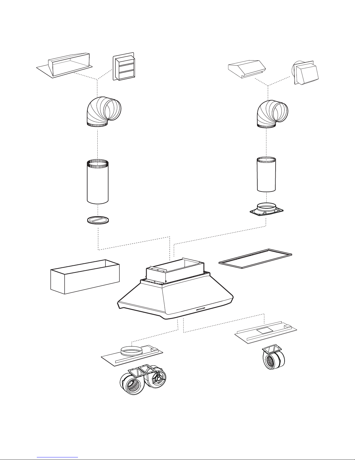
- IP29M SERIES RANGE HOOD SYSTEMS -
INTERIOR BLOWERS
MODEL 441
(10” ROUND WALL CAP)
MODEL 634 OR 644
OOF CAP)
(R
8” ROUND
ADJUSTABLE ELBOW,
OPTIONAL
MODEL 643
OUND WALL CAP)
(8” R
ODEL 410
M
(10” ROUND DUCT—
2 FT. SECTIONS)
M
ODEL 421
(10” ROUND VERTICAL IN-LINE
DAMPER, INCLUDED WITH
IQ12 AND P12
BLOWER/ROUGH-IN KITS)
OPTIONAL
DECORATIVE FLUE
AEIP SERIES
IP29M SERIES HOOD
BLOWER CONTROLS & LIGHTING.
REQUIRED FOR ALL INSTALLATIONS)
(C
ANOPY WITH
8” ROUND
STANDARD
8” R
OUND ADAPTER/DAMPER
DUCT
(INCLUDED WITH IQ6, P3 AND P6
BLOWER/ROUGH-IN KITS)
DRY WALL TRIM
OPTIONAL
ATDIP SERIES
MODEL iQ12 OR P12
BLOWER/ROUGH-IN KIT
CFM INTERIOR BLOWER &
(1200
HL0172
ROUGH-IN PLATE)
MODEL iQ6, P3 OR P6
BLOWER/ROUGH-IN KIT
(600 CFM (EXCEPT 300 CFM
FOR P3) INTERIOR BLOWER
& ROUGH-IN PLATE)
3
Page 4
M
ODEL 643
(8” ROUND
WALL CAP)
ODEL ILB3 (280 CFM)
M
IN-LINE BLOWER
(INCLUDES ONE 8” TO 10”
ROUND TRANSITION)
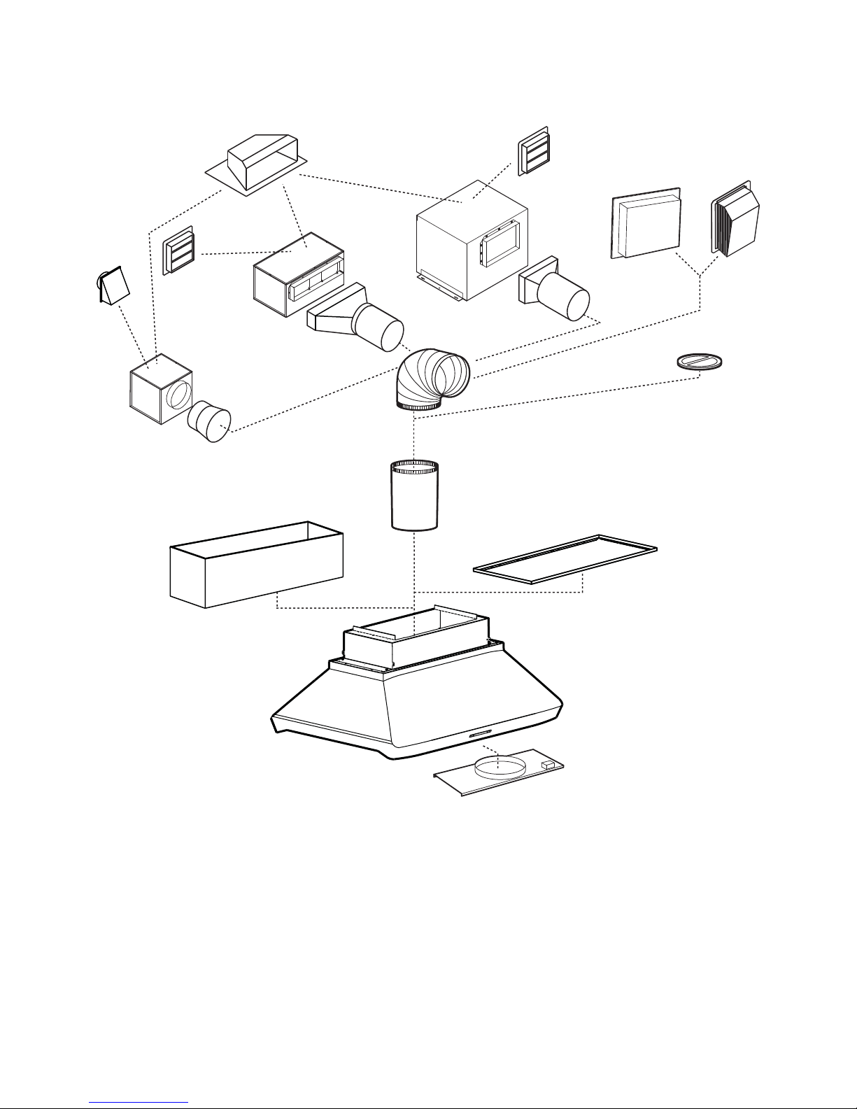
- IP29M SERIES RANGE HOOD SYSTEMS -
IN-LINE AND EXTERIOR BLOWERS
MODEL 437
(HIGH CAPACITY ROOF CAP)
ODEL 441
M
(10” ROUND
CAP)
WALL
MODEL ILB6 (600 CFM)
IN-LINE BLOWER
(INCLUDES TWO 4½” X 18½”
TO 10” ROUND TRANSITIONS)
ADJUSTABLE ELBOW,
M
ODEL ILB9 (800 CFM)
OR ILB11 (1100 CFM)
IN-LINE BLOWER
(INCLUDES TWO 8” X 12” TO
ROUND TRANSITIONS)
10”
M
ODEL 418
(10” ROUND
OPTIONAL)
MODEL 441
(10” ROUND WALL CAP)
ODEL 410
M
(10” ROUND DUCT—
2 FT. SECTIONS)
M
ODEL EB6 (600 CFM)
OR EB9 (900 CFM)
EXTERIOR BLOWER
(10” ROUND VERTICAL
IN-LINE DAMPER)
RECOMMENDED FOR USE
WITH EXTERIOR BLOWERS.
MODEL EB12 (1200 CFM)
OR EB15 (1500 CFM)
EXTERIOR BLOWER
ODEL 421
M
HL0090
OPTIONAL
DECORATIVE FLUE
AEIP SERIES
IP29M SERIES HOOD
(C
ANOPY WITH
BLOWER CONTROLS & LIGHTING.
REQUIRED FOR ALL INSTALLATIONS)
IN-LINE AND EXTERIOR
BLOWER ROUGH-IN KIT
(INCLUDED WITH EB6, EB9,
EB12, EB15, ILB3, ILB6,
ILB9 AND ILB11 BLOWERS)
OPTIONAL
DRY WALL TRIM
ATDIP SERIES
4
Page 5
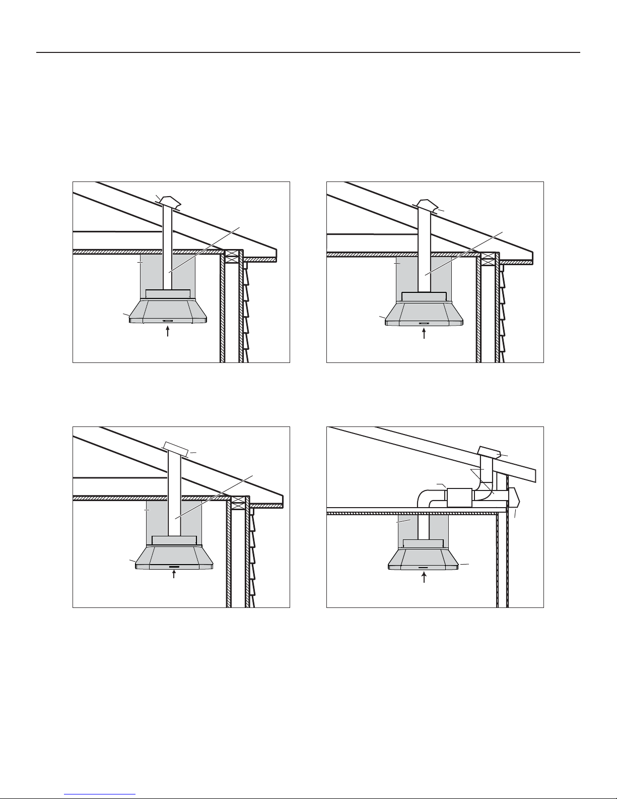
1. SELECT BLOWER OPTION AND INSTALLATION TYPE
Either an interior or an exterior blower or in-line blower may be used with this hood. The Best IP29M Series must be installed with blower
models iQ6, P3, P6, iQ12, P12, ILB3, ILB6, ILB9, ILB11, EB6, EB9, EB12 or EB15 only. Other blowers cannot be substituted. (Blowers
sold separately.)
Plan where and how the ductwork will be installed.
If installing in-line blower, refer to instructions packed with in-line blower and follow steps 1 up to 9, 11 to 15, 18 and up of this
manual.
Install proper-sized ductwork, elbows and roof or wall cap for the type of blower you are installing. Use metal duct tape to seal duct joints.
NOTE: It is recommended that there be a minimum of 6” of straight duct from this hood to an elbow for 8” ducting and 12” for 10” ducting.
ROOF CAP
ROOF CAP
8” (203) ROUND DUCT
10” (254) ROUND DUCT
DECORATIVE
12”, 18”, 24” or 30”
(305, 457, 610 or 762)
HH0165A
FLUE
or TRIM
HOOD
ABOVE COOKING SURFACE
NOTE: Dimensions in ( ) are in mm.
SINGLE INTERIOR BLOWER
DECORATIVE
12”, 18”, 24” or 30”
(305, 457, 610 or 762)
or TRIM
HOOD
30” TO 36” (762 to 914)
MODEL iQ6, P3 OR P6
TYPICAL DUCTWORK
EXTERIOR
BLOWER
FLUE
10” (254)
ROUND DUCT
DECORATIVE
12”, 18”, 24” or 30”
(305, 457, 610 or 762)
HH0166A
FLUE
or TRIM
HOOD
ABOVE COOKING SURFACE
NOTE: Dimensions in ( ) are in mm.
DUAL INTERIOR BLOWER
TYPICAL DUCTWORK
(except ILB3, 8’’ [203] ROUND DUCT)
DECORATIVE
12”, 18”, 24” or 30”
[305, 457, 610 or 762]
FLUE
or TRIM
30” TO 36” (762 to 914)
MODEL iQ12 OR P12
ROOF CAP
10” [254] ROUND DUCT
IN-LINE BLOWER
WALL
CAP
HOOD
30” TO 36” (762 to 914)
ABOVE COOKING SURFACE
HH0082A
NOTE: Dimensions in ( ) are in mm
MODEL EB6, EB9, EB12 OR EB15
EXTERIOR BLOWER
TYPICAL DUCTWORK
30” TO 36” [762 to 914]
HH0083A
ABOVE COOKING SURFACE
NOTE: Dimensions in [ ] are in mm.
MODEL ILB3, ILB6, ILB9 OR ILB11
IN-LINE BLOWER
TYPICAL DUCTWORK
5
Page 6
2. MEASURE INSTALLATION
!
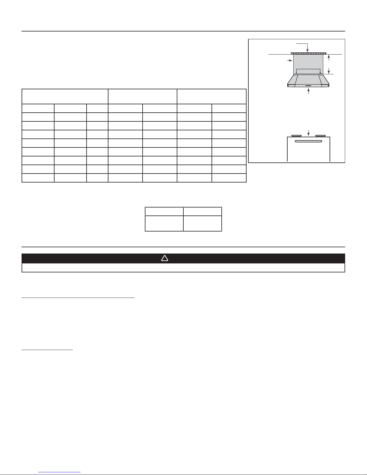
Dimensions for the most common installation are shown at right.
The minimum hood distance above cooktop must not be less than 30’’. A maximum of 36”
Framework
flush to ceiling
above cooktop is highly recommended for best capture of cooking impurities.
Distances over 36” are at the installer and users discretion.
Since framework must be flush to ceiling, 4 decorative flue covers have been created to fit both
hood widths and different ceiling heights. Refer to table below to choose the model that fits your
Decorative flue
cover or drywall
with trim
A
needs.
DECORATIVE FLUE COVER
DISTANCE
8’ CEILING
FROM COOKTOP
MODEL A (HEIGHT)WIDTH 30” 36” 30” 36”
AEIP422 12” 42” X
AEIP542 12” 54” X
DISTANCE
9’ CEILING
FROM COOKTOP
Minimum distance between
the hood and cooktop:
30’’ (762 mm)
Recommended maximum
distance between the hood
and cooktop: 36’’ (914 mm)
AEIP428 18” 42” X
AEIP548 18” 54” X
AEIP424 24” 42” X
AEIP544 24” 54” X
AEIP420 30” 42” X
AEIP540 30” 54” X
HH0084A
MINIMUM AND MAXIMUM DISTANCE
OVER COOKTOP
Standard 36”
(914 mm)
high cooktop
NOTE: For ceilings over 9’, decorative flues are not available.
If a drywall box will be built instead of installing decorative flue cover, use drywall trim to hide hood and drywall junction. Refer to table
below to find the appropriate model for your hood width.
MODEL WIDTH
ATDIP42
ATDIP54
42”
54”
3. PREPARE THE INSTALLATION
WARNING
When performing installation, servicing or cleaning the unit, it is recommended to wear safety glasses and gloves.
NOTE: Before proceeding to the installation, check the contents of the box. If items are missing or damaged, contact the manufacturer.
Remove the installation kit from inside the hood.
Make sure that the following items are included:
- Installation manual
- Accessories including:
• Hybrid baffle filters with handles (3 for 42” width hood, 5 for 54” width hood)
• Shielded halogen bulbs (GU10 type base, 120 V, 50 W) (6 for 42” width hood, 8 for 54” width hood)
• Bag of parts including:
(10) steel wood screws no. 10 x 1.5’’, (10) steel washer no. 10, (6) screws no. 8 x 3/8’’ (additional screws provided)
Parts sold separately:
- Interior blower model iQ6, P3 or P6 (includes rough-in plate and 8” round adapter and damper).
- Interior blower model iQ12 or P12 (includes rough-in plate and 10” round vertical in-line damper, model 421).
- In-line blower assembly model ILB3, ILB6, ILB9 or ILB11 (all include transition(s) and rough-in plate)
- Exterior blower assembly model EB6, EB9, EB12 or EB15 (all include rough-in plate).
- Duct, elbows, dampers, wall and roof caps. Refer to pages 3 and 4 for a complete list of venting options and model numbers.
- Optional decorative flue cover AEIP Series, 12’’, 18”, 24” or 30” height and 42” or 54” width.
- Optional dry wall trim ATDIP Series, 42” or 54” width.
LINKLOGIC® ENABLED HOOD
This hood includes the LinkLogic system which allows communication over ordinary household electrical wiring to other LinkLogic devices
including the Broan Smart Sense Fan system. If you intend to use this hood with another LinkLogic device, follow the instructions found in
Section 21 along with the instructions that come with the LinkLogic device you plan to use.
6
Page 7
4. PREPARE THE BLOWER HOUSING
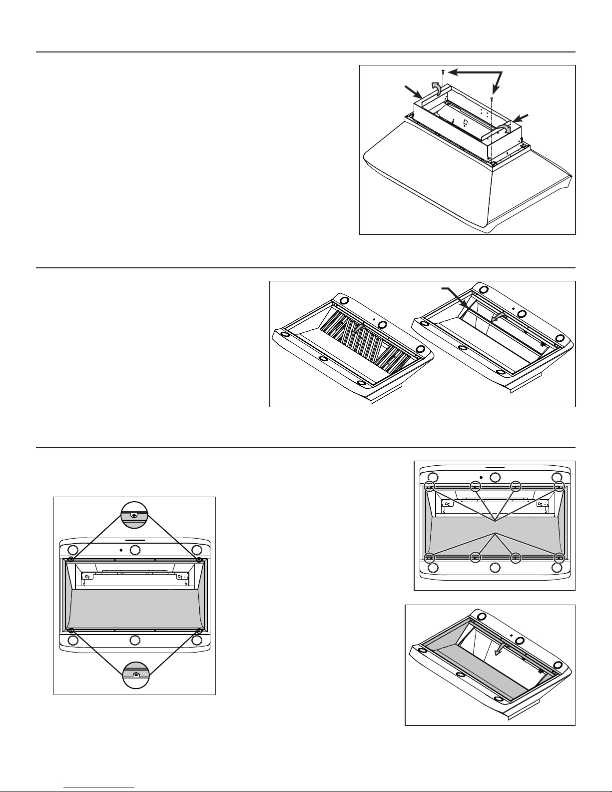
Detach the blower housing from the hood by removing both retaining screws (A).
Keep the screws for further use.
Fold up both flanges (B). The flanges must be perpendicular to the top of the
blower housing.
HD0229
5. REMOVE THE FILTERS AND THE GREASE DRIP RAIL
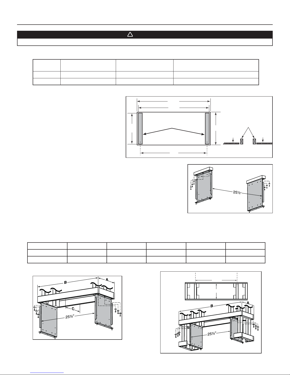
A. Remove tape on filters. Remove filters from hood and
set aside.
NOTE: It is recommended to start with the center one.
B. Remove tape on grease drip rail (1).
Lift out grease drip rail and set aside.
A
B
B
1
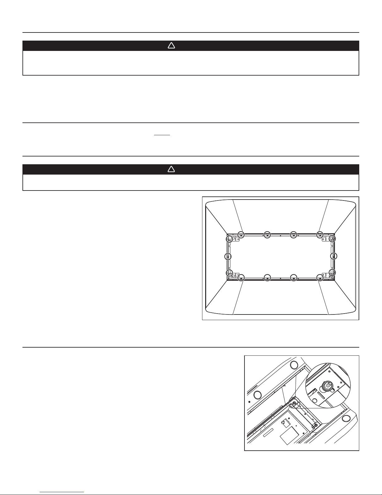
6. REMOVE THE PAN
NOTE: Do not remove the 4 screws located on the
notched parts of the pan (A on figure below).
A
HD0223
A
HD0222
Using a Phillips no. 2, remove 8 screws
retaining the pan (shaded part on
illustration at right) to the hood.
Remove the pan and set aside.
RETAINING SCREWS LOCATION
HD0224
HD0238
7
Page 8
7. BUILD THE FRAMEWORK
!
WARNING
When building framework, always follow all applicable construction codes and standards.
The framework must be sized to support the total weight of the hood. Refer to the table below for total weight of the hood, according to
the type of blower chosen.
HOOD WIDTH
42” 71
54” 86
WITH IQ6, P3 OR P6
INTERIOR BLOWER
LB. 84 LB. 52 LB.
LB. 99 LB. 67 LB.
7.1 SUGGESTED FRAMEWORK FOR INSTALLATION WITH DECORATIVE FLUE COVER AEIP SERIES
WITH IQ12 OR P12
INTERIOR BLOWER
WITH IN-LINE OR EXTERIOR BLOWER
(ROUGH-IN PLATE ONLY)
28¾”
28½”
In the ceiling material, cut-out a 28¾” x 12½” max.
opening over the installation location. Install two
supporting studs inside the cut-out at dimensions
shown at right.
12½”
max.
HD0227A
SUPPORTING STUDS
C
L
27”
5
12 /
8”
C
L
Studs flush
with ceiling material
Ceiling
material
Using provided wood screws no. 10 x 1.5” and washers, assemble both mounting brackets
(included with the optional decorative flue cover) to the framework. See illustration at right.
HD0228A
7.2 SUGGESTED FRAMEWORK FOR INSTALLATION WITH DRYWALL TRIM ATDIP SERIES
Below is the suggested framework for both 42” and 54” width hoods to be installed with drywall trim ATDIP Series. Refer to the table
and illustrations below for the dimensions according to the hood width. Using provided wood screws no. 10 x 1.5” and washers,
assemble both mounting brackets (included with the optional drywall trim) to the framework.
HOOD WIDTH A WITH 5/8” DRYWALL A WITH 1/2” DRYWALL B WITH 5/8” DRYWALL B WITH 1/2” DRYWALL C
5
42” 11
/8”11
54” 11 5/8”11
FRAMEWORK 42” HOOD
7
/8” 28 5/8” 28 7/8” 10” MINIMUM
7
/8” 40 5/8” 40 7/8” 10” MINIMUM
FRAMEWORK 54” HOOD
C
L
27¼”
C
L
FRAMEWORK
TOP VIEW
C
Ceiling
material
HD0235A
HD0237A
8
Page 9
8. INSTALL BLOWER HOUSING
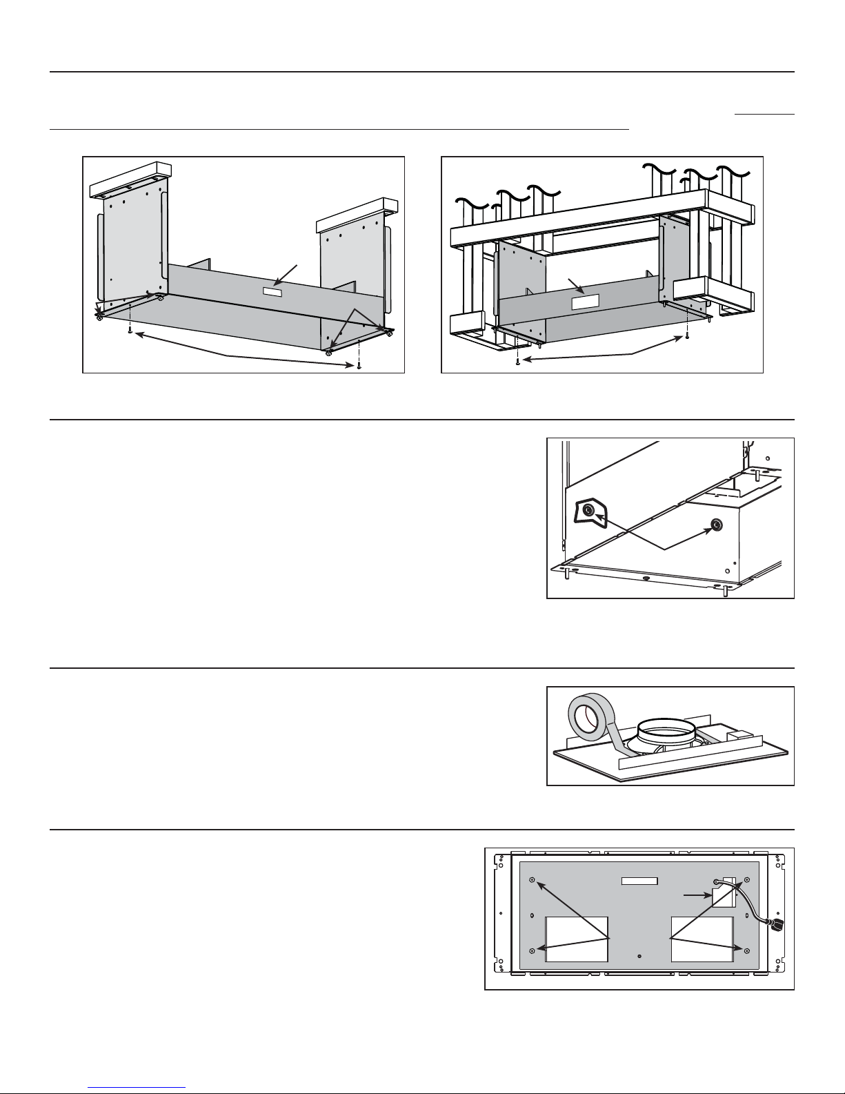
Use both screws (A) previously removed in step 4 to assemble the blower housing to the mounting brackets. For installation with decorative
flue cover AEIP Series only, place 4 nuts (B) (from flue cover parts bag) on the pem studs, leaving 1/4” for the hood installation. The blower
housing must be installed in such a way that its label (C) will be on the same side as the hood control side. See illustrations below.
INSTALLATION WITH DECORATIVE FLUE COVER AEIP SERIES
INSTALLATION WITH DRYWALL TRIM ATDIP SERIES
C
B
HD0230
A
C
B
HD0231
9. SECURE BLOWER HOUSING TO BRACKETS
From the inside, secure the blower housing to mounting brackets, using 2 no. 8 x 3/8” screws
per side.
Screws must be installed in embossed sections, see details at right.
RETAINING SCREWS LOCATION
HO0100
10. INSTALL 8” ROUND ADAPTER AND DAMPER TO ROUGH-IN PLATE
(iQ6, P3 OR P6 INTERIOR BLOWERS ONLY)
A
Attach transition to iQ6, P3 or P6 blower rough-in plate.
Use metal duct tape to make all joints secure and air-tight.
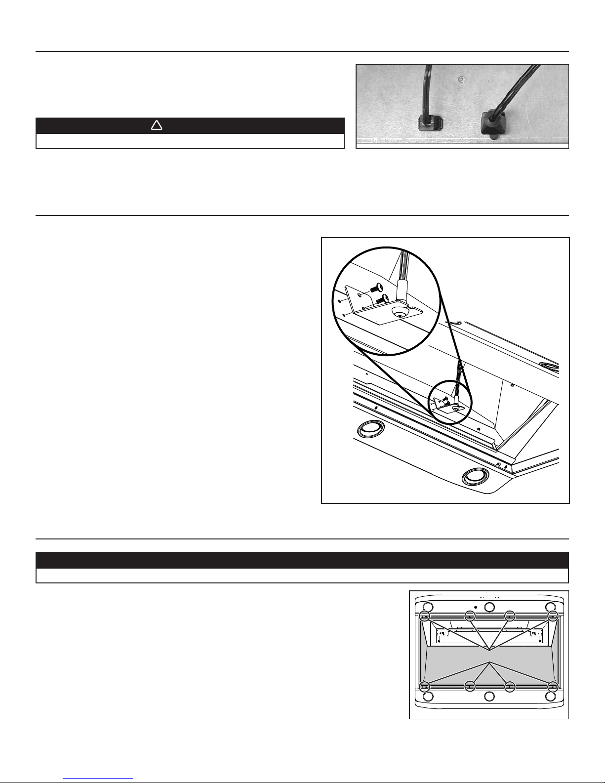
11. INSTALL THE ROUGH-IN PLATE IN THE BLOWER HOUSING
Run power cable to installation location. Refer to the instructions included with
the selected blower/rough-in kit (sold separately) for details on installing the
rough-in plate. Install the rough-in plate so that the wiring box is located on the
right side when facing the hood, as specified on the blower housing label.
Connect adapter/damper or rough-in plate (according to blower model) to
ductwork. Use metal duct tape to make all joints secure and air-tight.
HO0196
WIRING COVER
LOCK NUTS
HD0232
9
Page 10
12. CONNECT THE WIRING
!
!
WARNING
Risk of electric shock. Electrical wiring must be done by qualified personnel in accordance with all applicable
codes and standards. Before connecting wires, switch power off at service panel and lock service disconnecting
means to prevent power from being switched on accidentally.
Remove wiring cover from rough-in plate and set aside.
Connect wires as follow: BLACK to BLACK, WHITE to WHITE and GREEN or bare wire under GREEN ground screw. DO NOT FORGET
TO CONNECT THE GROUND. Reinstall wiring cover.
13. FINISH THE DRYWALL BOX (INSTALLATION WITH DRYWALL TRIM ATDIP SERIES ONLY)
Finish the drywall box. Check fitting with dry wall trim before mounting it to the hood.
14. MOUNT THE DECORATIVE FLUE COVER OR THE DRYWALL TRIM ON THE HOOD
WARNING
The decorative flue cover AEIP Series and the drywall trim ATDIP Series may have sharp edges. Be careful when
handling and installing these metal parts.
14.1 INSTALLATION WITH DECORATIVE FLUE COVER AEIP SERIES
Remove the protective plastic film covering the decorative flue
cover AEIP Series. Assemble the flue cover on top of hood using
(14) no. 8 x 3/8” screws (provided with decorative flue cover). See
illustration at right to locate mounting screws from top of hood.
NOTE: Ensure edges fit perfectly before tightening completely the
mounting screws.
14.2 INSTALLATION WITH DRYWALL TRIM ATDIP SERIES
Remove the protective plastic film covering the drywall trim ATDPI
Series. Assemble the drywall trim on the top of the hood using
(14) no. 8 x 3/8” screws (provided with drywall trim). See illustration
at right to locate mounting screws from top of hood.
NOTE: Ensure edges fit perfectly before tightening completely the
mounting screws.
HD0233
15. INSTALL THE HOOD
15.1 INSTALLATION WITH DECORATIVE FLUE COVER AEIP SERIES
Assemble the hood assembly to the mounting brackets by aligning keyholes with
4 nuts previously installed in step 8 (2 nuts per side). While holding the hood, remove
one nut and install a washer (included in parts bag) on each pem stud, then reinstall
the nut and tighten it. See illustration at right.
MOUNTING SCREWS LOCATION
15.2 INSTALLATION WITH DRYWALL TRIM ATDIP SERIES
Align hood keyholes with pem studs on brackets. Secure the hood to the brackets
using washers and nuts (included in parts bag). See illustration at right.
HD0234
10
Page 11
16. INSTALL THE BLOWER (INTERIOR OR EXTERIOR BLOWER)
!
Refer to instructions included with blower.
Once the blower is installed, plug the blower cord (A) into the female receptacle
and the power supply cord (B) onto the male connector inside the hood.
WARNING
AB
Do not plug the two cords into each other.
HE0078
17. INSTALL THE CALIBRATION BUTTON BRACKET IN THE HOOD
(iQ6 AND iQ12 INTERIOR BLOWERS ONLY)
Both iQ6 and iQ12 blowers are equipped with a calibration button
already mounted to its own bracket. Install this bracket in the hood, using
2 screws provided with iQ6 or iQ12 interior blower.
18. REINSTALL THE PAN
Remove protective plastic film covering pan sides and tape over halogen lamps.
Using a Phillips no. 2 or Robertson no. 2 screwdriver and the retaining screws, reinstall the pan
(previously removed in step 6) inside the hood (shaded part on illustration at right).
HD0540
CAUTION
RETAINING SCREWS LOCATION
HD0224
11
Page 12
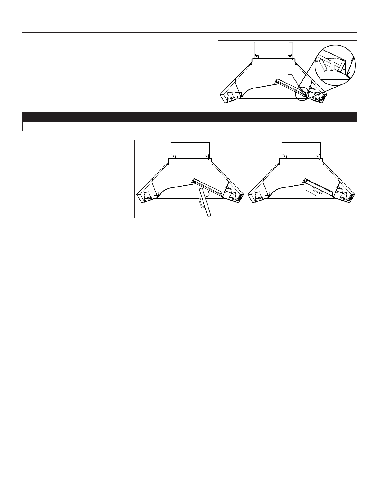
19. REINSTALL GREASE DRIP RAIL AND BAFFLE FILTERS
Reinstall grease drip rail (1). The illustration at right shows how to reinsert the
grease drip rail(s) into the range hood.
HD0225
CAUTION
Remove protective plastic film covering hybrid baffle filters before installing them.
Reinstall hybrid baffle filters on the hood.
It is recommended to install side filters first
and finish with center one.
1. Insert one end of hybrid baffle filter into
the front channel of the hood.
2. Raise the other end toward the inside of
hood and insert in the grease drip rail of
the hood.
Replacement filters are available from your
dealer. See label inside hood for size and
part number.
HD0226
12
1
12
Page 13
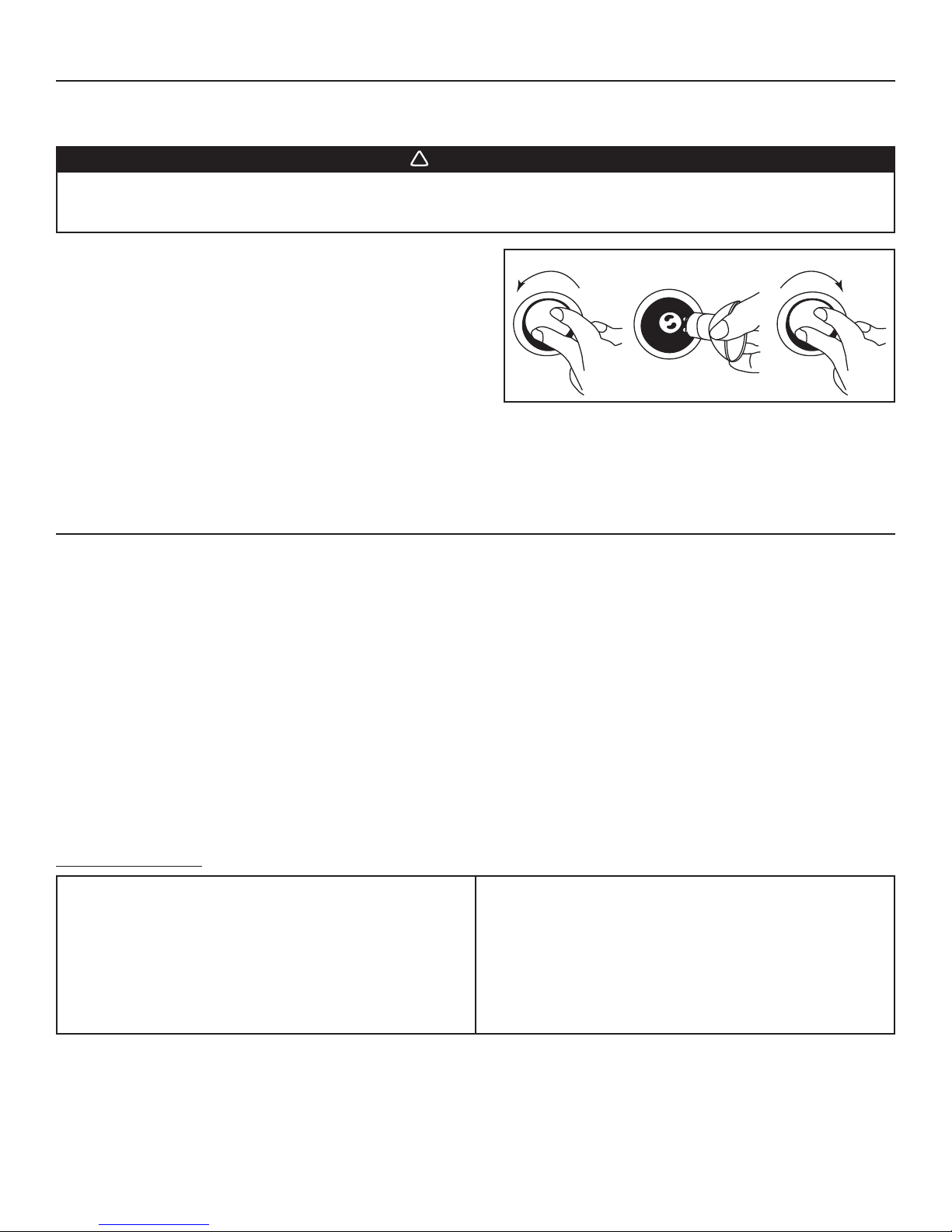
20. LIGHT BULBS REPLACEMENT
!
This hood requires shielded halogen lamps (120 V, 50 W, MR16 with GU10 base or PAR16 with GU10 base), included.
NOTE: Before using lamps, remove shipping tape on them (if present).
WARNING
Do not touch lamps during or soon after operation. Burns may occur. In order to prevent the risk of personal injury,
only install shielded halogen lamps. Also, never install a cool beam, a dichroic lamp, a lamp not suitable for use in
recessed luminaires or identified for use in enclosed fixtures.
1. To remove lamps, gently push upwards and turn counterclockwise to
disengage bulb leads from their grooves.
NOTE: If need be, use a rubber dishwashing glove to add grip when
removing the bulb.
2. Install the new lamps by placing the bulb leads into their grooves in
the socket.
3. Gently push upwards and turn clockwise until secure.
NOTE: If need be, use a rubber dishwashing glove to add grip when
removing the bulb; or use suction cup tool available from Best
to ease removal of the bulbs. Contact Best Technical Support at
1-800-558-1711 to order suction cup tool, part number 99526707.
12 3
HO0089
21. USE AND CARE
Hybrid Baffle Filters
The hybrid baffle filters should be cleaned frequently. Use a warm detergent solution. Wash more often if your cooking style generates
greater grease—like frying foods or wok cooking.
Remove hybrid baffle filters by pushing them towards the back of hood and rotating filters downward. Baffle filters are dishwasher safe.
Allow filters to dry completely before reinstalling them in the hood.
Clean all-metal filters in the dishwasher using a non-phosphate detergent. Discoloration of the filter may occur if using phosphate detergent
or as a result of local water conditions — but this will not affect filter performance. This discoloration is not covered by the warranty.
Grease Drip Rail
The grease drip rail should be cleaned frequently. Lift it out from the hood and use a warm detergent solution. As for the baffle filters, wash
more often if your cooking style generates greater grease—like frying foods or wok cooking. Allow grease drip rail to dry completely before
reinstalling it in the hood.
Blower Cleaning
Remove the filters in order to access the blower. Vacuum blower to clean. Do not immerse in water. Refer to blower instruction manual for
more details.
Hood cleaning
Stainless steel cleaning: How to maintain its “BRIGHT LOOK”
Do:
• Regularly wash with clean cloth or rag soaked with warm water
and mild soap or liquid dish detergent.
• Always clean in the direction of original polish lines.
• Always rinse well with clear water (2 or 3 times) after cleaning.
Wipe dry completely.
• You may also use a specialized household stainless steel
cleaner.
Don’t:
• Use any steel or stainless steel wool or any other scrapers to
remove stubborn dirt.
• Use any harsh or abrasive cleansers.
• Allow dirt to accumulate.
• Let plaster dust or any other construction residues reach the
power pack. During construction/renovation, cover the power
pack to make sure no dust sticks to stainless steel surface.
Avoid when choosing a detergent:
- Any cleaners that contain bleach will attack stainless steel.
- Any products containing: chloride, fluoride, iodide, bromide will deteriorate surfaces rapidly.
- Any combustible products used for cleaning such as acetone, alcohol, ether, benzol, etc., are highly explosive and should never be
used close to a range.
13
Page 14
22. OPERATION
Always turn ON your hood before you begin cooking in order to establish an air flow in the kitchen. Let the blower run for a few minutes to
clear the air after you turn off the range. This will help keep the whole kitchen cleaner and brighter.
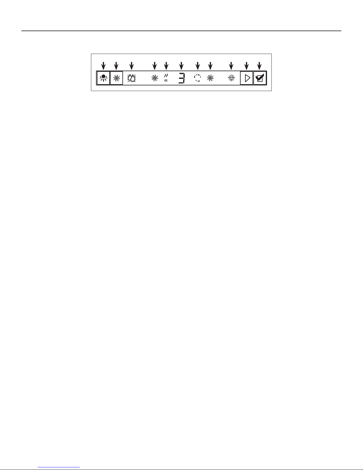
12 5 67 8 910 11 34
max
HC0032
1. Halogen light push button/
LinkLogic® Master Link Mode push button
2. Blower push button
3. Enable/Disable functions push button/
LinkLogic® Erase Link push button
4. Grease filter reset push button/
LinkLogic® Link Mode push button
5. Grease filters maintenance icon
S
O
N
R
E
S
AIR
REFRESH
6. Maximum blower speed icon
7. Particulates sensor icon
8. Blower speed level/
LinkLogic® state icon
9. Air refresh fuction icon
10. Blower speed icon
11. LinkLogic® icon
Cooktop Lighting (Halogen)
• The halogen lighting is controlled by the light push-button (item 1 on illustration above). Push once to turn ON the lights, and push a second
time to turn the lights ON to a brighter level. If the lights are at the highest level, pressing another time will set them to the lowest intensity.
• Press on the push-button and maintain for 1 second to turn Off the lights and set the memorized intensity. When turned on, the halogen
bulbs will light cooktop at the previous setting.
• Use 120 V, 50 W, MR16 with GU10 base or PAR16 with GU10 base, shielded halogen lamps (included).
Blower
• The blower is controlled by the blower push-button (item 2 on illustration above). Push once to turn ON the blower, and push a second
time to set the blower speed to a higher level. If the blower speed is on maximum level, pressing another time will turn the blower to the
lowest speed.
• When power level 1 is activated from OFF, 100% of power level is activated during 0.3 second acting as a “kick-start”.
• Press on the push-button and maintain for 1 second to turn Off the blower and set the memorized speed. When turned ON, the blower
will operate at the previous setting.
• When the blower is ON, the speed level is shown by the center icon (item 8 on illustration above) while the icon 10 appears (the speed
of the rotational movement is proportional to the blower speed).
• When the blower is on the higher speed, the icon 10 shuts off and the icon 6 appears with “max” (the symbol has a rotational movement).
Functions
Pressing on Enable/Disable functions push-button (item 3 on illustration above) allows to control Particulate Sensor and Air Refresh hood
functions.
Particulates Sensor
• To activate the particulate sensor function, press on Enable/Disable functions push-button (item 3 on illustration above), the particulates
sensor icon (item 7 on illustration above) will appear.
• When the sensor is activated, the blower turns ON automatically when some particulates, vapors or smokes caused by cooking
process, or abnormal gas emissions in the environment are detected. The blower speed is automatically set depending on the
particulates amount and the sensibility settings of the particulates sensor. See next paragraph.
• To stop the particulates sensor function, press on Enable/Disable functions push-button until particulates sensor icon turns off.
Particulates sensor sensibility settings
• Press on Enable/Disable functions push-button (item 3 on illustration above) to activate the particulate sensor function, this will light up
the particulates sensor icon (item 7 on illustration above). Then, press and maintain for 2 seconds the Enable/Disable functions push-button:
the sensor sensivity level will appear on center icon (item 8 on illustration above).
• Press again on this push-button to change the sensor sensitivity level (from 0 [minimum sensitivity] up to 9 [maximum sensitivity]).
• Press on the grease filter reset push button (item 4 on the illustration above) to confirm (or is confirmed automatically after 5 seconds).
Air Refresh
• To activate the air refresh function, press on Enable/Disable functions push-button (item 3 on illustration above), the air refresh
function icon (item 9 on illustration above) will appear.
• To stop the air refresh function, press on Enable/Disable functions push-button until air refresh icon turns off.
• Air refresh function activates only when blower is OFF. When activated, the blower hood recycles the air in the environment in perfect
silence, starting every 50 minutes (for 10 minutes, on first speed).
Grease filter reset
• Once the grease filter cleaning is done, press on the grease filter reset push-button (item 4 on control illustration) to reset the filter
maintenance timer. This will also shut off the grease filter maintenance icon (item 5 on control illustration).
14
Page 15
23. OPERATION (CONT'D)
!
Grease filter maintenance indicator
• After 30 hours of operation, the grease filter maintenance icon (item 5 on control illustration) appears. This means filters need to be
cleaned.
• Once the grease filter cleaning is done, press on grease filter reset push-button to reset the filter maintenance timer.
Interface backlighting
• Off mode (Blower off, Particulates sensor and Air refresh modes disabled): Backlighting is off.
• Halogen lighting activated: does not affect backlighting.
• Blower turns on: Backlighting at maximum intensity.
• Particulates sensor and Air refresh mode activated: Backlighting at maximum intensity.
• Particulates sensor at sensitivity settings and Air refresh in activated mode: Backlighting at minimum intensity.
HEAT SENTRY™
This hood is equipped with a HEAT SENTRY™ thermostat. This thermostat is a device that will start or speed up the blower if it senses
excessive heat above the cooking surface.
• If blower is OFF—it turns the blower to speed 3 (blower speed icon shows H).
• If blower is ON—it turns the blower up to speed 3 (blower speed icon shows H).
NOTE: When Heat Sentry™ is activated, Air refresh mode and Particulate sensor are inactivated. Also, communication coming from
the LinkLogic® Module is disabled.
WARNING
The HEAT SENTRY can start the blower during a range top re or other excessive heat situations even if the hood is turned off. In this
case, it is impossible to turn the blower OFF using control panel buttons. If you must stop the blower, unplug the blower power cord
(located behind the lters) from the hood by pulling on its 2-prong connector; do not pull on the wire.
• When the temperature level drops to normal, the blower will return to its original setting (blower speed icon will show the original
blower speed).
• To turn off the blower when Heat Sentry™ is activated, press and hold the blower push-button (item 2 on illustration) for more than
1 second.
LinkLogic® Network compatibility
Your IP29M Series range hood can be linked to LinkLogic network, if installed in your house.
LINKLOGIC LINKING INSTRUCTIONS
A. ACTIVATE THE “LINK” MODE OF THE HOOD
Push the LinkLogic link mode push-button (item 4 on control illustration) for 2 seconds; the LinkLogic icon of the interface (item 11 on
control illustration) should be visible and backlighting is full intensity at that point.
LINK FOR WALL REMOTE CONTROL, REMOTE CONTROL
REMOTE BLOWER MODULES
OR
ACTIVATE THE “LINK” MODE OF THE LINKLOGIC DEVICE
Push the “link” button of the LinkLogic device for
a specific duration to activate its link mode
(see instructions of LinkLogic device).
STA RT THE “A UTO-LINK” PROCESS OF THE HOOD
Push the LinkLogic link mode push-button
(item 4 on illustration) to start the “Auto-Link” process,
flashing “A” should be visible (item 8 on control illustration)
on the interface until link is done.
NOTE: For some LinkLogic devices, no “A” will be flashing
because the linking duration is too short.
LINK FOR SMARTSENSE™ OR MAKE-UP AIR MODULES
GO TO STEP 22 (ON NEXT PA GE ) TO CONFIGURE LINKLOGIC BOARD
JUMPERS BASED ON BLOWER PERFORMANCE.
STA RT THE “MASTER LINK” PROCESS OF THE HOOD
Push the LinkLogic master link mode push-button
(item 1 on illustration) to start the “Master Link” process,
flashing “L” should be visible (item 8 on control illustration)on
the hood interface, meaning that the hood is waiting for a
SmartSense™ or Make-Up Air module to link.
ACTIVATE THE “LINK” MODE OF THE LINKLOGIC DEVICE
Push the “link” button of the LinkLogic device
(see instructions of device for location) for a specific duration to
activate its Link mode. Wait for the “L” to disappear from the
hood interface to do next step.
Go back to the appropriate first step if another LinkLogic device
needs to be linked. Otherwise, to exit “link” mode, go to
B. EXIT LINK MODE OF THE HOOD
Press and hold LinkLogic link mode push-button (item 4 on control illustration) for 2 seconds to exit “link” mode. Link mode remains
activated for 4 minutes if no other operation is done.
LINK OF ANOTHER LINKLOGIC DEVICE
E
XIT LINK MODE OF THE HOOD.
15
Page 16
23. OPERATION (CONT'D)
ERASE LINK PROCESS
A. ACTIVATE THE “LINK” MODE OF THE HOOD
Push the LinkLogic link mode push-button (item 4 on control illustration) for 2 seconds; the LinkLogic icon of the interface (item 11 on
control illustration) should be visible and backlighting is full intensity at that point.
B. ERASE ALL LINKED LINKLOGIC DEVICES
Push the LinkLogic erase link push-button (item 3 on control illustration) for 2 seconds to start the “Erase Link” process, flashing “E”
should be visible (item 8 on control illustration) on the hood interface until links are erased.
C. EXIT “LINK” MODE OF THE HOOD
Press and hold LinkLogic link mode push-button (item 4 on control illustration) for 2 seconds to exit “link” mode. Link mode remains
activated for 4 minutes if no other operation is done.
NOTE: If during normal operation of the range hood, the LinkLogic Icon (item 11 on control illustration) starts blinking, an error occurred
while communicating with a linked LinkLogic device. To reset this error flag, customer needs to enter and exit the Linking mode
as explained previously. This will erase the error flag until it happens again. If the problem happens again, it is recommended to
erase all links and start back the whole linking process.
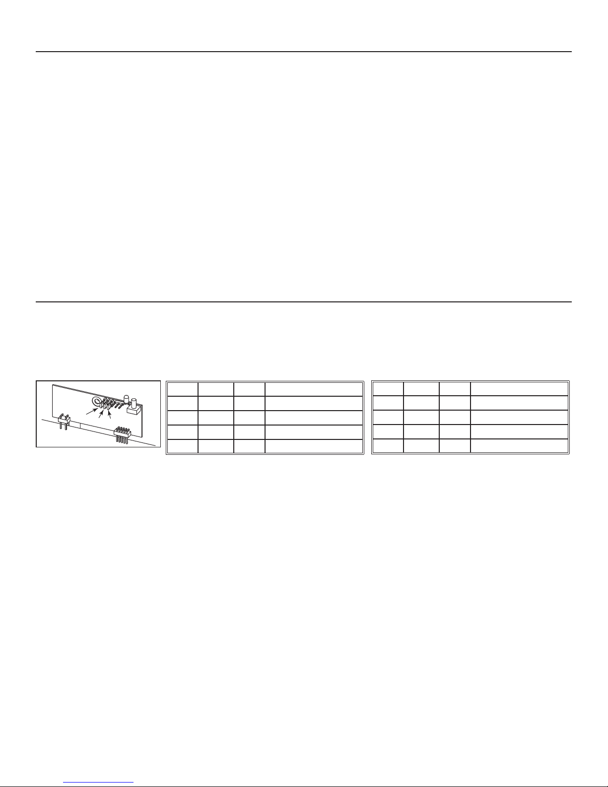
24. LINKLOGIC SYSTEM CONTROL BOARD JUMPERS
The LinkLogic system is designed to work with devices like the Broan Smart Sense Fan system that requires CFM output or this range
hood. If you are using this hood with a LinkLogic device that requires CFM information, please follow the simple instruction/matrix below to
configure the LinkLogic control board in the hood to provide the correct CFM information. To access the LinkLogic control board, remove
baffle filters, grease drip rail and hood pan (see steps 5 and 6). Remove both screws retaining the control panel to the hood. Rotate
carefully the control panel in order to see the LinkLogic board jumpers. Remove jumpers from current location on pins and reconfigure
based on blower performance.
Pin 1 Pin 2 Pin 3 Maximum CFM value
0 0 0 0 CFM
3
2
1
HE0089
LINKLOGIC BOARD JUMPERS
If you are unsure if the LinkLogic accessory or device requires CFM data, please refer to the unit’s instructions.
0 0 1 300 CFM
0 1 0 500 CFM
0 1 1 600 CFM
0 = No jumper on pin.
1 = Jumper on pin.
Pin 1 Pin 2 Pin 3 Maximum CFM value
1 0 0 900 CFM
1 0 1 1000 CFM
1 1 0 1200 CFM
1 1 1 1500 CFM
0 = No jumper on pin.
1 = Jumper on pin.
16
Page 17
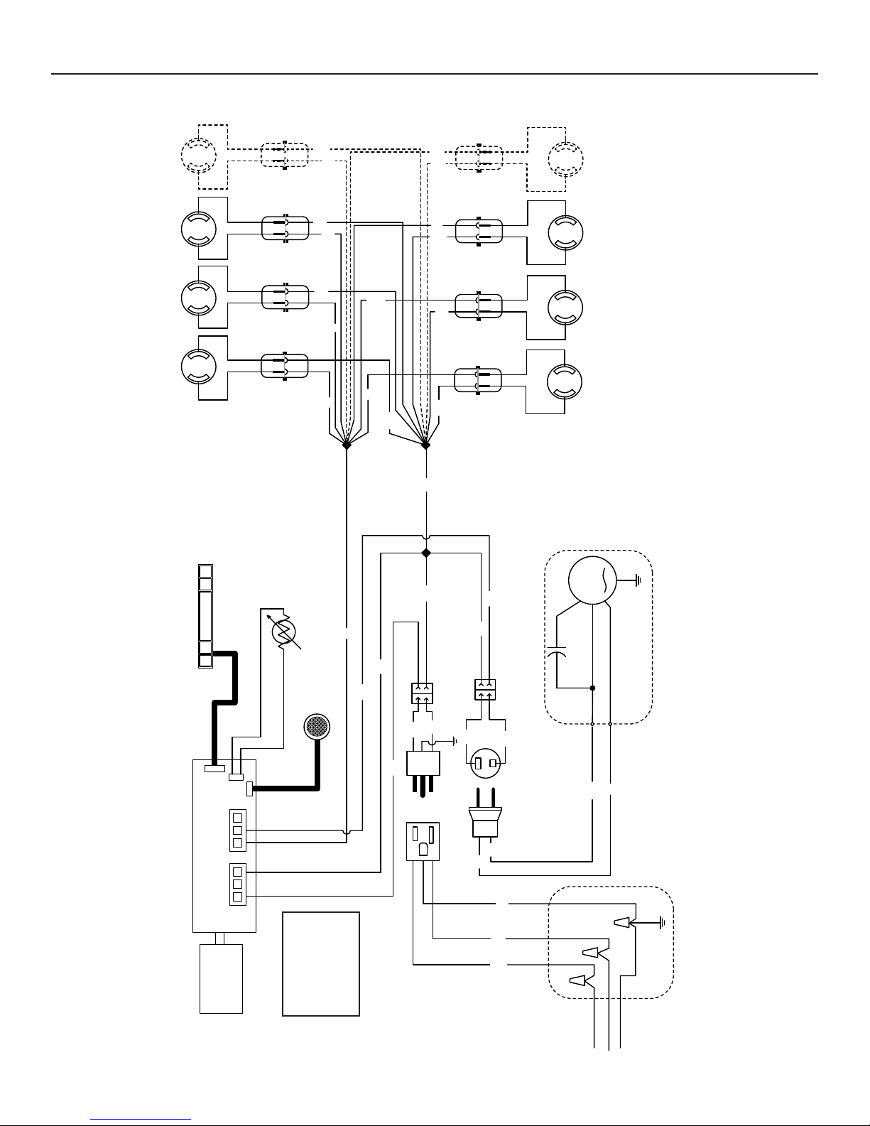
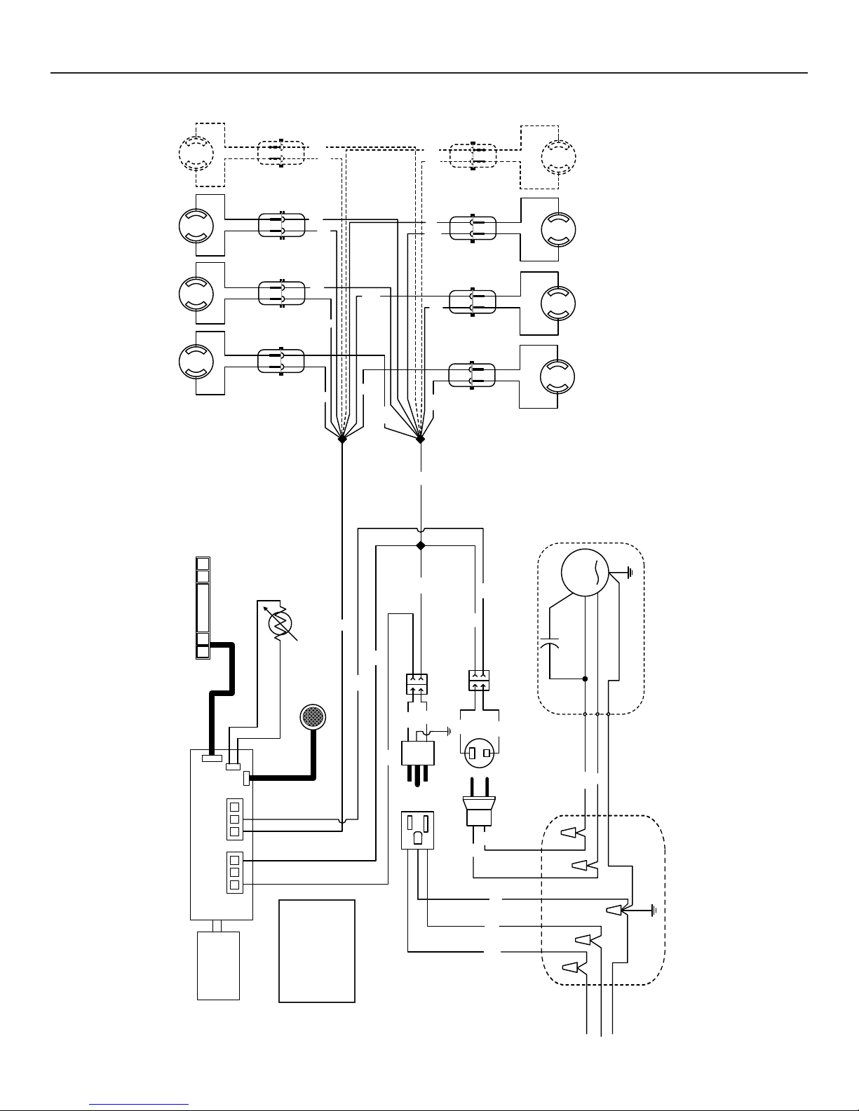
25. WIRING DIAGRAMS
INTERIOR BLOWER
Y
YY
WW W
LIGHT SOCKET LIGHT SOCKET LIGHT SOCKET LIGHT SOCKET
USER INTERFACE
Y
EAT SENTRY
H
Y
Y
Y
W
Y
W
B
Y
WW
W
W
W
W
B
W
LIGHT SOCKET LIGHT SOCKET LIGHT SOCKET LIGHT SOCKET
M
MOTOR
INTERNAL BLOWER ASSEMBLY
J5 J6
321 321
(INSTEON)
COMMUNICATION
BOARD
ARTICULATES SENSOR
P
COLOR CODE
B BLACK
G GREEN
W WHITE
W
B
B
Y YELLOW
B
W
B
W
B
W
G
W
B
LINE
GROUND
NEUTRAL
120 V SUPPLY
ROUGH-IN PLATE
HE0183A
17
Page 18
25. WIRING DIAGRAMS (CONT'D)
IN-LINE OR EXTERIOR BLOWER
Y
YY
WW W
LIGHT SOCKET LIGHT SOCKET LIGHT SOCKET LIGHT SOCKET
USER INTERFACE
Y
EAT SENTRY
H
Y
Y
Y
W
Y
W
B
Y
WW
W
W
W
W
B
W
LIGHT SOCKET LIGHT SOCKET LIGHT SOCKET LIGHT SOCKET
M
MOTOR
REMOTE BLOWER ASSEM BLY
J5 J6
321 321
(INSTEON)
COMMUNICATION
BOARD
ARTICULATES SENSOR
P
COLOR CODE
B BLACK
G GREEN
W WHITE
W
B
B
Y YELLOW
B
W
B
W
GROUND
B
W
G
W
B
LINE
GROUND
NEUTRAL
120 V SUPPLY
ROUGH-IN PLATE
HE0184A
18
Page 19

26. WARRANTY
Broan-NuTone LLC (Broan-NuTone) warrants to the original consumer purchaser of Best products that such products will be free from defects
in materials or workmanship for a period of one year from the date of original purchase. THERE ARE NO OTHER WARRANTIES, EXPRESS
OR IMPLIED, INCLUDING, BUT NOT LIMITED TO, IMPLIED WARRANTIES OR MERCHANTABILITY OR FITNESS FOR A PARTICULAR
PURPOSE.
During this one-year period, Broan-NuTone will, at its option, repair or replace, without charge, any product or part which is found to be
defective under normal use and service.
THIS WARRANTY DOES NOT EXTEND TO FLUORESCENT LAMP STARTERS, TUBES, HALOGEN AND INCANDESCENT BULBS,
FUSES, FILTERS, DUCTS, ROOF CAPS, WALL CAPS AND OTHER ACCESSORIES FOR DUCTING. This warranty does not cover (a)
normal maintenance and service or (b) any products or parts which have been subject to misuse, negligence, accident, improper maintenance
or repair (other than by Broan-NuTone), faulty installation or installation contrary to recommended installation instructions.
The duration of any implied warranty is limited to the one-year period as specified for the express warranty. Some states or provinces do not
allow limitation on how long an implied warranty lasts, so the above limitation may not apply to you.
BROAN-NUTONE’S OBLIGATION TO REPAIR OR REPLACE, AT BROAN-NUTONE’S OPTION, SHALL BE THE PURCHASER’S
SOLE AND EXCLUSIVE REMEDY UNDER THIS WARRANTY. BROAN-NUTONE SHALL NOT BE LIABLE FOR INCIDENTAL,
CONSEQUENTIAL OR SPECIAL DAMAGES ARISING OUT OF OR IN CONNECTION WITH PRODUCT USE OR PERFORMANCE.
Some states or provinces do not allow the exclusion or limitation of incidental or consequential damages, so the above limitation
or exclusion may not apply to you.
This warranty gives you specific legal rights, and you may also have other rights, which vary from state to state or province to another. This
warranty supersedes all prior warranties.
To qualify for warranty service, you must (a) notify Broan-NuTone at the address stated below or telephone number stated below, (b) give the
model number and part identification and (c) describe the nature of any defect in the product or part. At the time of requesting warranty service,
you must present evidence of the original purchase date.
In USA - Best®, 926 W. State Street, Hartford, WI 53027 (800-558-1711)
In Canada - Best®, 550 Lemire Blvd., Drummondville, QC, Canada, J2C 7W9 (866-737-7770)
WARRANTY
ONE-YEAR LIMITED WARRANTY FOR BEST PRODUCTS
www.BestRangeHoods.com
19
Page 20

27. SERVICE PARTS
IP29M Series
1
2
5
3
4
6
7
8
9
10
HL0216
KEY NO.PART NO.DESCRIPTION
1 SV08069 CONTROL PROCESSOR UNIT 11
2 SV08073 PARTICULATES SENSOR 11
3 SV13924 MALE CONNECTOR 11
4 SV13923 FEMALE CONNECTOR 11
5 SV08074 C
6 SV05917 S
7 SV09435 SOCKET HOLDER GU10 6 8
8 SV09434 LIGHT TRIM STAINLESS STEEL 68
9 SV05921 S
10
11
* SV03435
* SV08072 INSTALLATION GUIDE 11
* SV08068
* SV05869 B
* N
OT SHOWN.
KEY NO.PART NO.DESCRIPTION
* SV06927
OT SHOWN.
* N
SV61639 H
SV61640 HYBRID BAFFLE FILTER WITH MICROMESH AND HANDLE 11.84” X 8.61” X 1” 2 -
SV61934 GREASE DRIP RAIL FOR 42” HOOD 1SV61935 G
ONTROL INTERFACE 11
OCKET GU10 6 8
HIELDED HALOGEN BULBS (50W, 120 V, PAR16, GU10) 6 8
YBRID BAFFLE FILTER WITH MICROMESH AND HANDLE 8.84” X 8.61” X 1” 1 5
REASE DRIP RAIL FOR 54” HOOD -1
H
EAT SENTRY™ THERMISTOR
PARTS BAG: STEEL WOOD SCREW NO. 10 X 1.5” (10),
SCREWS NO. 8 X 3/8” (6), STEEL WASHERS NO. 10 (10)
EST LOGO 11
ACCESSORY PARTS BAG : STEEL HEXAGONAL LOCK-NUT (5),
SCREWS NO. 8 X 3/8” (14), STEEL WASHERS NO. 10 (10),
STEEL WOOD SCREW NO. 10 X 1.5” (10)
DECORATIVE FLUE DRYWALL TRIM
11
QTY. (HOOD WIDTH)
42” 54”
11
11
QUANTITY
11
REPLACEMENT PARTS AND REPAIRS
In order to ensure your unit remains in
good working condition, you must use
Broan-NuTone genuine replacement
parts only. Broan-NuTone genuine
replacement parts are specially
designed for each unit and are
manufactured to comply with all the
applicable certification standards and
maintain a high standard of safety.
Any third party replacement part
used may cause serious damage and
drastically reduce the performance
level of your unit, which will result
in premature failing. Broan-NuTone
recommends to contact a certified
service depot for all replacement
parts and repairs.
20
Page 21

GUIDE D’INSTALLATION
HB0063
SÉRIE IP29M
! !
CONÇUE UNIQUEMENT POUR LA CUISSON DOMESTIQUE
LIRE ET CONSERVER CES DIRECTIVES
INSTALLATEUR : LAISSER CE GUIDE AU PROPRIÉTAIRE.
PROPRIÉTAIRE : DIRECTIVES D’UTILISATION ET D’ENTRETIEN
EN PAGES 33 À 36.
BEST; Hartford, Wisconsin www.BestRangeHoods.com 800-558-1711
BEST; Drummondville, QC, Canada www.BestRangeHoods.com 866-737-7770
Pour enregistrer votre produit en ligne ou pour obtenir plus d’information, consultez notre site www.BestRangeHoods.com
SV08072 rév. 15
Page 22

!
AVERTISSEMENT
!
AVERTISSEMENT
AFIN DE RÉDUIRE LES RISQUES D’INCENDIE,
D’ÉLECTROCUTION OU DE BLESSURES
CORPORELLES, SUIVEZ LES DIRECTIVES SUIVANTES :
1. N’utilisez cet appareil que de la façon prévue par le
manufacturier. Si vous avez des questions, contactez le
manufacturier à l’adresse ou au numéro de téléphone indiqués
dans la garantie.
2. Avant de réparer ou de nettoyer l’appareil, couper l’alimentation
électrique en verrouillant le panneau de distribution afin
d’éviter sa remise en marche accidentelle. Si le panneau de
distribution ne peut être verrouillé, y fixer un avertissement en
évidence, telle qu’une étiquette de couleur vive.
3. Les travaux d’installation et de raccordement électrique doivent
être effectués par une personne qualifiée, conformément
aux codes et aux standards de construction, incluant ceux
concernant la protection contre les incendies.
4. Une quantité d’air adéquate est requise afin d’assurer une
bonne combustion et l’évacuation des gaz par la cheminée
dans le cas des équipements alimentés au gaz afin de prévenir
les retours de cheminée. Conformez-vous aux instructions et
aux standards de sécurité des manufacturiers d’équipement de
chauffage, tel qu’ils sont publiés par la National Fire Protection
Association (NFPA) et l’American Society for Heating,
Refrigeration and Air Conditioning Engineers (ASHRAE) ainsi
que les responsables des codes locaux.
5. Veillez à ne pas endommager le câblage électrique ou d’autres
équipements non apparents lors de la découpe ou du perçage
du mur ou du plafond.
6. Les ventilateurs avec conduits doivent toujours évacuer l’air
à l’extérieur.
7. Ne pas utiliser cet appareil avec une commande de vitesse à
semi-conducteur additionnelle.
8. Afin de réduire les risques d’incendie, n’utilisez que des conduits
de métal.
9. Cet appareil doit être mis à la terre.
10. Lorsqu’une réglementation est en vigueur et qu’elle comporte
des exigences d’installation et/ou de certification plus
restrictives, lesdites exigences prévalent sur celles de ce
document et l’installateur entend s’y conformer à ses frais.
AFIN DE RÉDUIRE LES RISQUES DE FEU
DE CUISINIÈRE :
a) Ne jamais laisser les appareils de cuisson sans surveillance
lorsqu’ils sont réglés à feu vif. Les débordements engendrent
de la fumée et des déversements graisseux pouvant
s’enflammer. Chauffez l’huile lentement, à feu doux ou moyen.
b) Mettez toujours la hotte en marche lorsque vous cuisinez à feu
vif ou que vous cuisinez des mets flambés (par ex. : crêpes
Suzette, cerises jubilé, steaks au poivre flambés).
c) Nettoyez régulièrement la (les) roue(s) du ventilateur. Ne
laissez pas la graisse s’accumuler sur le ventilateur, les filtres
ou les conduits d’évacuation.
d) Utilisez le bon format de casserole. Servez-vous toujours de
casseroles et d’ustensiles appropriés à la dimension de la
surface chauffante.
22
AFIN D’ÉVITER TOUT RISQUE DE BLESSURES LORS
D’UN FEU DE CUISINIÈRE, SUIVEZ CES DIRECTIVES* :
1. Étouffez les flammes avec un couvercle hermétique,
une tôle à biscuits ou un plateau métallique et ensuite,
éteindre le brûleur. PRENEZ SOIN D’ÉVITER LES
BRÛLURES. SI LES FLAMMES NE S’ÉTEIGNENT PAS
IMMÉDIATEMENT, ÉVACUEZ LES LIEUX ET APPELEZ
LES POMPIERS.
2. NE PRENEZ JAMAIS UNE CASSEROLE EN FLAMMES
DANS VOS MAINS. Vous pourriez vous brûler.
3. N’UTILISEZ PAS D’EAU, incluant un linge à vaisselle ou une
serviette mouillée, cela pourrait occasionner une violente
explosion de vapeur.
4. N’utilisez un extincteur QUE DANS LE CAS OÙ :
A. Vous savez qu’il s’agit d’un extincteur de classe ABC et
que vous en connaissez le fonctionnement.
B. L’incendie est petit et limité à l’endroit où il a débuté.
C. Les pompiers ont été avisés.
D. Vous pouvez combattre l’incendie en ayant accès à une sortie
de secours.
*Tirées du Kitchen Fire Safety Tips publié par la NFPA.
ATTENTION
1. Pour une utilisation à l’intérieur seulement.
2. Pour usage domestique seulement. Ne pas utiliser pour évacuer
des vapeurs ou des matières dangereuses ou explosives.
3. Afin d’éviter tout dommage au moteur et de débalancer ou de
rendre bruyante la roue du moteur, garder votre appareil à l’abri
des poussières de gypse et de construction/rénovation, etc.
4. Le moteur de votre hotte possède une protection thermique
qui éteindra automatiquement le moteur s’il devient surchauffé.
Le moteur redémarrera automatiquement une fois refroidi. Si
le moteur continue à arrêter et à redémarrer, faites-le vérifier.
5. Pour une meilleure évacuation des odeurs de cuisson, le bas
de votre hotte devrait être situé à un minimum de 30 po et à un
maximum de 36 po au-dessus de la table de cuisson.
6. Deux installateurs sont recommandés lors de l’installation vu
la grande dimension et le poids de cette hotte.
7. Afin de réduire les risques d’incendie, assurez-vous d’évacuer
l’air à l’extérieur. Ne pas évacuer l’air dans des espaces
restreints comme l’intérieur des murs ou plafond ou dans le
grenier, faux plafond ou garage.
8. Cet appareil est équipé d’un thermostat pouvant faire démarrer
le ventilateur automatiquement. Afin de réduire le risque de
blessure, couper le courant à partir du panneau électrique et le
verrouiller ou apposer un avertissement sur le panneau afin de
prévenir que la hotte ne soit mise en marche accidentellement.
9. En raison de la grande capacité d’évacuation de cette hotte, il
est recommandé d'utiliser un dispositif d'apport d'air approprié
ou d’ouvrir une fenêtre dans ou près de la cuisine afin de
remplacer l’air évacué.
10. Afin de réduire les risques d’incendie et d’électrocution, la
hotte Best de série IP29M doit être installée uniquement avec
un des ventilateurs intérieurs Best suivants : iQ6, P3, P6, iQ12
ou P12, ou un des ventilateurs extérieurs Best suivants : EB6,
EB9, EB12 ou EB15, ou un des ventilateurs en ligne Best
suivants : ILB3, ILB6, ILB9 ou ILB11 (vendus séparément).
Aucun autre ventilateur ne doit être utilisé.
11. Veuillez consulter l’autocollant apposé à l’intérieur de la hotte
pour plus d’information ou autres exigences.
Page 23

- SYSTÈME DE HOTTE DE CUISINIÈRE SÉRIE IP29M -
MODÈLE 437
(CAPUCHON DE TOIT À HAUT RENDEMENT)
M
ODÈLE 418
(COUDE AJUSTABLE
DE 10 PO ROND,
OPTIONNEL).
VENTILATEURS INTÉRIEURS
MODÈLE 441
(CAPUCHON MURAL 10 PO ROND)
MODÈLE 634 OU 644
APUCHON DE TOIT)
(C
COUDE AJUSTABLE
DE 8 PO ROND,
OPTIONNEL
MODÈLE 643
APUCHON MURAL DE 8 PO ROND)
(C
ODÈLE 410
M
(CONDUIT DE 10 PO ROND,
SECTIONS DE 2 PI)
M
ODÈLE 421
(VOLET VERTICAL EN LIGNE DE
10 PO ROND INCLUS AVEC LES
VENTILATEURS/PLAQUES
VENTILATEUR IQ12 ET P12)
CHEMINÉE
DÉCORATIVE OPTIONNELLE
SÉRIE AEIP
(A
VEC COMMANDES VENTILATEUR
ET ÉCLAIRAGE. REQUISE POUR
TOUTES LES INSTALLATIONS.)
HOTTE SÉRIE IP29M
CONDUIT STANDARD
8 PO ROND
DE
A
DAPTATEUR/VOLET DE 8 PO ROND
(INCLUS AVEC LES
VENTILATEURS/PLAQUES VENTILATEUR
Q6, P3 ET P6)
I
JOINT DÉCORATIF
OPTIONNEL
SÉRIE ATDIP
MODÈLE iQ12 OU P12
VENTILATEUR/PLAQUE
VENTILATEUR
HL0172
(VENTILATEUR INTÉRIEUR DE
1200 PI/MIN ET
PLAQUE VENTILATEUR)
MODÈLE iQ6, P3 OU P6
VENTILATEUR/
PLAQUE VENTILATEUR
(VENTILATEUR INTÉRIEUR DE
600 PI/MIN (SAUF 300 PI/MIN
POUR P3) ET PLAQUE VENTILATEUR)
23
Page 24

- SYSTÈME DE HOTTE DE CUISINIÈRE SÉRIE IP29M -
VENTILATEURS EN LIGNE ET EXTÉRIEURS
MODÈLE 437
(CAPUCHON DE TOIT À HAUT RENDEMENT)
MODÈLE ILB9 (800 PI/MIN)
OU ILB11 (1100 PI/MIN)
VENTILATEUR EN LIGNE
(INCLUANT 2 TRANSITIONS DE
8 PO X 12 PO À
10 PO ROND)
M
ODÈLE 441
(CAPUCHON MURAL 10 PO ROND)
M
ODÈLE EB6 (600 PI/MIN)
OU EB9 (900 PI/MIN)
VENTILATEUR EXTÉRIEUR
MODÈLE EB12 (1200 PI/MIN)
OU EB15 (1500 PI/MIN)
VENTILATEUR EXTÉRIEUR
MODÈLE 643
(CAPUCHON MURAL
DE 8 PO ROND)
ODÈLE ILB3 (280 PI/MIN)
M
VENTILATEUR EN LIGNE
(INCLUANT UNE TRANSITION
RONDE DE 8 PO À 10 PO)
MODÈLE 441
(CAPUCHON MURAL
10 PO ROND)
ODÈLE ILB6 (600 PI/MIN)
M
VENTILATEUR EN LIGNE
(INCLUANT 2 TRANSITIONS DE
4½ PO X 18½ PO À
10 PO ROND)
(COUDE AJUSTABLE
DE 10 PO ROND,
ODÈLE 418
M
OPTIONNEL)
ODÈLE 410
M
(CONDUIT DE 10 PO ROND,
SECTIONS DE 2 PI)
MODÈLE 421
(VOLET VERTICAL EN LIGNE DE
10 PO ROND.) RECOMMANDÉ
POUR UTILISATION AVEC LES
VENTILATEURS EXTÉRIEURS.
JOINT DÉCORATIF
OPTIONNEL
SÉRIE ATDIP
HL0090
CHEMINÉE
DÉCORATIVE OPTIONNELLE
SÉRIE AEIP
HOTTE SÉRIE IP29M
VEC COMMANDES VENTILATEUR
(A
ET ÉCLAIRAGE. REQUISE POUR
TOUTES LES INSTALLATIONS).
PLAQUE VENTILATEUR POUR
VENTILATEURS EXTÉRIEURS OU EN LIGNE
(INCLUSE AVEC LES VENTILATEURS
EB6, EB9, EB12, EB15, ILB3,
ILB6, ILB9 ET ILB11).
24
Page 25

1. SÉLECTIONNER L'OPTION VENTILATEUR ET LE TYPE D'INSTALLATION
Cette hotte fonctionne autant avec un ventilateur intérieur, en ligne ou extérieur. La hotte de modèle Best de série IP29M doit être installée uniquement avec l’un des ventilateurs suivants : iQ6, P3, P6, iQ12, P12, ILB3, ILB6, ILB9, ILB11, EB6, EB9, EB12 ou EB15 (vendus
séparément).
Aucun autre ventilateur ne peut être utilisé.
Déterminer à quel endroit et de quelle façon les conduits seront installés.
Si un ventilateur en ligne est installé, se reporter aux directives fournies avec celui-ci et suivre les étapes 1 à 9, 11 à 15, 18 et
suivantes de ce guide.
Installer des conduits de dimension adéquate, coude(s) et capuchon de mur ou de toit selon le type de ventilateur. Se servir de ruban
adhésif pour conduits en métal pour assurer l’étanchéité des joints.
NOTE : Pour des conduits de 8 po, il est recommandé d'avoir un minimum de 6 po de long de conduit droit entre la hotte et un coude, et
pour des conduits de 10 po, cette longueur est de 12 po minimum.
CAPUCHON
DE TOIT
CHEMINÉE DÉCORATIVE
HH0165F
12 po, 18 po,
24 po ou 30 po
(305, 457, 610 ou 762)
ou JOINT DÉCORATIF
HOTTE
DE 30 po À 36 po (762 à 914)
AU-DESSUS DE LA
NOTE : Les dimensions entre ( ) sont en mm.
SURFACE DE CUISSON
INSTALLATION TYPE
VENTILATEUR INTÉRIEUR SIMPLE
MODÈLE iQ6, P3 OU P6
VENTILATEUR
EXTÉRIEUR
CONDUIT ROND
DE 8 po (203)
CONDUIT ROND
DE 10 po (254)
CAPUCHON
DE TOIT
CHEMINÉE DÉCORATIVE
HH0166F
12 po, 18 po,
24 po ou 30 po
(305, 457, 610 ou 762)
ou JOINT DÉCORATIF
HOTTE
DE 30 po À 36 po (762 à 914)
AU-DESSUS DE LA
NOTE : Les dimensions entre ( ) sont en mm.
SURFACE DE CUISSON
INSTALLATION TYPE
VENTILATEUR INTÉRIEUR DOUBLE
MODÈLE iQ12 OU P12
CAPUCHON DE TOIT
CONDUIT ROND DE 10 po [254]
(sauf ILB3, CONDUIT ROND DE 8 po [203])
VENTILATEUR EN LIGNE
CONDUIT ROND
DE 10 po (254)
CHEMINÉE DÉCORATIVE
HH0082F
12 po, 18 po,
24 po ou 30 po
(305, 457, 610 ou 762)
ou JOINT DÉCORATIF
HOTTE
DE 30 po À 36 po (762 à 914)
AU-DESSUS DE LA
NOTE : Les dimensions entre ( ) sont en mm.
SURFACE DE CUISSON
INSTALLATION TYPE
VENTILATEUR EXTÉRIEUR
MODÈLE EB6, EB9, EB12 OU EB15
HEMINÉE DÉCORATIVE
HH0083F
25
12 po, 18 po,
24 po ou 30 po
[305, 457, 610 ou 762]
ou JOINT DÉCORATIF
HOTTE
DE 30 po À 36 po [762 à 914]
AU-DESSUS DE LA
SURFACE DE CUISSON
NOTE : Les dimensions entre [ ] sont en mm.
INSTALLATION TYPE
VENTILATEUR EN LIGNE
MODÈLE ILB3, ILB6, ILB9 OU ILB11
CAPUCHON
MURAL
Page 26

2. MESURER L’INSTALLATION
!
Les dimensions des installations les plus courantes sont indiquées ci-contre.
La distance minimale entre le bas de votre hotte et la surface de cuisson ne doit pas
être inférieure à 30 po. Un maximum de 36 po au-dessus de la surface de cuisson
est fortement recommandé pour une meilleure évacuation des odeurs de cuisson.
Une distance de plus de 36 po demeure à la discrétion de l’installateur et de l’utilisateur.
Cheminée décorative
Structure de soutien
au ras du plafond
ou cloison et
joint décoratif
A
Puisque la structure de soutien doit être au même niveau que le plafond, 4 cheminées
décoratives ont été conçues afin de compléter une installation selon différentes hauteurs
de plafond et largeurs de hotte. Consulter le tableau ci-dessous pour connaître les
modèles et leurs applications.
CHEMINÉE DÉCORATIVE
PLAFOND DE 8 PI
DISTANCE
DE LA SURFACE
DE CUISSON
PLAFOND DE 9 PI
DISTANCE
DE LA SURFACE
DE CUISSON
MODÈLE A (HAUT.) LARG. 30 PO 36 PO 30 PO 36 PO
Distance minimale entre la
hotte et la surface de cuisson :
30 po (762 mm)
Distance maximale recommandée
entre la hotte et la surface
de cuisson : 36 po (914 mm)
AEIP422 12 PO 42 PO X
AEIP542 12
AEIP428 18 PO 42 PO X
AEIP548 18 PO 54 PO X
AEIP424 24 PO 42 PO X
AEIP544 24 PO 54 PO X
AEIP420 30 PO 42 PO X
AEIP540 30
PO 54 PO X
PO 54 PO X
Cuisinière standard
de 36 po (914 mm)
HH0084F
de hauteur
DISTANCES MINIMALE ET MAXIMALE
AU-DESSUS DE LA SURFACE DE CUISSON
NOTE : Il n’existe pas de cheminée décorative pour des plafonds de plus de 9 pi.
Si au lieu d’une cheminée décorative une cloison est construite, utiliser un joint décoratif pour cacher la jonction entre la hotte et la cloison.
Voir ci-dessous pour choisir le modèle approprié à la largeur de votre hotte.
MODÈLE LARGEUR
ATDIP42
ATDIP54
42 PO
54 PO
3. PRÉPARER L’INSTALLATION
AVERTISSEMENT
Il est recommandé de porter des lunettes et des gants de sécurité lors de l’installation, de l’entretien et de la
réparation de cet appareil.
NOTE : Avant de commencer l'installation, vérifier le contenu de la boîte. Si des pièces sont manquantes ou endommagées, contacter le manufacturier.
Retirer la trousse d’installation de l’intérieur de la hotte.
S’assurer que les articles suivants soient inclus :
- Guide d’installation
- Les accessoires incluant :
• Filtres à chicane hybrides avec poignées (3 pour la hotte de 42 po de largeur, 5 pour la hotte de 54 po de largeur)
• Ampoules halogènes avec écran (120 V, 50 W, avec culot GU10)
(6 pour la hotte de 42 po de largeur, 8 pour la hotte de 54 po de largeur)
• Le sac de pièces incluant : (10) vis à bois en acier n° 10 x 1,5 po, (10) rondelles d’acier n° 10, (6) vis n° 8 x 3/8 po (vis en surplus)
Pièces vendues séparément :
- Ventilateur intérieur modèle iQ6, P3 ou P6 (incluant la plaque ventilateur et l’adaptateur/volet de 8 po rond).
- Ventilateur intérieur modèle iQ12 ou P12 (incluant la plaque ventilateur et le volet intérieur de 10 po rond vertical, modèle 421).
- Ensemble de ventilateur en ligne modèle ILB3, ILB6, ILB9 ou ILB11 (tous incluant la (les) transition(s) et la plaque ventilateur).
- Ensemble de ventilateur extérieur, modèle EB6, EB9, EB12 ou EB15 (tous incluant la plaque ventilateur).
- Conduits, coudes, volets, capuchons de mur ou de toit. Consulter les pages 23 et 24 pour la liste complète des accessoires de ventilation
et les numéros de modèle.
- Cheminée décorative optionnelle série AEIP de 12 po, 18 po, 24 po ou 30 po de hauteur et de 42 po ou 54 po de largeur.
- Joint décoratif optionnel série ATDIP de 42 po ou 54 po de largeur.
HOTTE AVEC MODULE LINKLOGIC®
Cette hotte est munie du système LinkLogic permettant la communication, par le biais du câblage électrique régulier de la maison, avec
d’autres dispositifs LinkLogic incluant le système Smart Sense Fan de Broan. Si vous désirez utiliser cette hotte avec un autre dispositif
LinkLogic, veuillez suivre les instructions de la section 21 ainsi que les instructions fournies avec l’autre dispositif LinkLogic.
26
Page 27

4. PRÉPARER LA CHAMBRE DE VENTILATEUR
B
Détacher la chambre de ventilateur de la hotte en retirant ses 2 vis de retenue (A).
Garder les vis pour usage ultérieur.
Plier vers le haut ses 2 ailettes (B) de façon à ce qu’elle soient perpendiculaires
au-dessus de la chambre de ventilateur.
HD0229
5. RETIRER LES FILTRES À CHICANE HYBRIDES ET LA GOUTTIÈRE
1
A. Enlever le ruban adhésif des filtres à chicane hybrides.
Retirer les filtres de la hotte et les mettre de côté.
NOTE : Il est recommandé de retirer le filtre central
en premier.
B. Enlever le ruban adhésif de la gouttière (1).
Dégager la gouttière de la hotte et la mettre de côté.
A
B
6. RETIRER LE CADRE INTÉRIEUR
NOTE : Ne pas enlever les 4 vis situées dans les
encoches du cadre (A dans l’illustration
ci-dessous).
A
HD0223
A
HD0222
À l’aide d’un tournevis Phillips n° 2,
enlever les vis retenant le cadre
intérieur (la pièce colorée en gris dans
l’illustration ci-contre) à la hotte.
Retirer le cadre intérieur et le mettre
de côté.
EMPLACEMENT DES VIS
HD0224
HD0238
27
Page 28

7. CONSTRUIRE LA CHARPENTE
!
AVERTISSEMENT
Lors de la construction de la charpente, toujours suivre les codes et standards de construction en vigueur.
Construire la charpente en fonction du format et du poids total de la hotte. Consulter le tableau ci-dessous pour connaître le poids total de
la hotte selon le type de ventilateur choisi.
LARGEUR DE HOTTE
42
PO 71 LB 84 LB 52 LB
AVEC VENTILATEUR INTÉRIEUR
IQ6, P3 OU P6
54 PO 86 LB 99 LB 67 LB
7.1 CHARPENTE SUGGÉRÉE POUR UNE INSTALLATION AVEC CHEMINÉE DÉCORATIVE DE SÉRIE AEIP
AVEC VENTILATEUR INTÉRIEUR
Q12 OU P12
I
AVEC VENTILATEUR EN LIGNE OU EXTÉRIEUR
(PLAQUE VENTILATEUR SEULEMENT)
28¾ po
28½ po
Découper une ouverture de 28¾ po x 12½ po max.
dans le matériau du plafond, au-dessus de
l’emplacement prévu pour la hotte. Installer deux
poutrelles de support à l’intérieur de la découpe
12½ po
max.
POUTRELLES DE SUPPORT
12 /
poutrelles au même niveau
que le matériau de plafond
5
8 po
matériau
de plafond
aux dimensions indiquées ci-contre.
C
L
HD0227F
C
L
27 po
À l’aide de vis à bois n° 10 x 1,5 po et de rondelles (fournies), assembler les deux supports
latéraux (inclus avec la cheminée décorative optionnelle) à la charpente. Voir l’illustration
ci-contre.
HD0228F
7.2 CHARPENTE SUGGÉRÉE POUR UNE INSTALLATION AVEC JOINT DÉCORATIF DE SÉRIE ATDIP
Voici la charpente suggérée pour des hottes de 42 po et de 54 po de largeur à être installées avec un joint décoratif de série ATDIP.
Consulter le tableau et les illustrations ci-dessous pour connaître les dimensions selon la largeur de hotte. À l’aide de vis à bois
n° 10 x 1,5 po et de rondelles (fournies), assembler les deux supports latéraux (fournis avec le joint décoratif) à la charpente.
LARGEUR DE HOTTE A AVEC PA RO I DE 5/8 PO A AVEC PAR O I DE 1/2 PO B AVEC PAR O I DE 5/8 PO B AVEC PAR OI DE 1/2 PO C
42” 11 5/8 PO 11 7/8 PO 28 5/8 PO 28 7/8 PO 10 PO MINIMUM
54” 11 5/8 PO 11 7/8 PO 40 5/8 PO 40 7/8 PO 10 PO MINIMUM
CHARPENTE POUR HOTTE DE 54 PO
CHARPENTE POUR HOTTE DE 42 PO
VUE DU
DESSUS
CHARPENTE
LA
DE
C
L
27¼ po
C
C
L
matériau
de plafond
HD0235F
HD0237F
28
Page 29

8. INSTALLER LA CHAMBRE DE VENTILATEUR
Utiliser les deux vis (A) retirées précédemment à l’étape 4 pour assembler la chambre de ventilateur aux supports latéraux. Seulement
pour une installation avec la cheminée décorative de série AEIP, visser les 4 écrous (B) (provenant du sac de pièces de la cheminée
décorative) sur les tiges filetées, en laissant 1/4 po pour l’installation de la hotte. La chambre de ventilateur doit être installée de façon à
ce que son étiquette (C) soit du même côté que la commande de la hotte. Voir les illustrations ci-dessous.
INSTALLATION AVEC LA CHEMINÉE DÉCORATIVE DE SÉRIE AEIP
C
B
HD0230
A
B
INSTALLATION AVEC LE JPOINT DÉCORATIF DE SÉRIE ATDIP
C
HD0231
9. FIXER LA CHAMBRE DE VENTILATEUR AUX SUPPORTS LATÉRAUX
Par l’intérieur, fixer la chambre de ventilateur aux supports latéraux, à l’aide de 2 vis
n° 8 x 3/8 po par côté.
Les vis doivent se trouver dans les sections embossées, voir les détails ci-contre.
EMPLACEMENT DES VIS
A
HO0100
10. INSTALLER L’ADAPTATEUR/VOLET DE 8 PO ROND À LA PLAQUE VENTILATEUR
(VENTILATEUR INTÉRIEUR iQ6, P3 OU P6 SEULEMENT)
Fixer l’adaptateur/volet de 8 po rond à la plaque ventilateur.
Sceller tous les joints avec du ruban à conduits.
HO0196
11. INSTALLER LA PLAQUE VENTILATEUR DANS LA CHAMBRE DE VENTILATEUR
Amener le câble d’alimentation à l’emplacement de la hotte. Pour les détails
concernant l’installation de la plaque ventilateur, voir les instructions comprises
avec l’ensemble ventilateur et plaque ventilateur (vendu séparément). Installer
la plaque ventilateur de façon à ce que son boîtier électrique se trouve à droite
lorsque vous faites face à la hotte, tel qu’il est spécifié sur l’étiquette de la
chambre de ventilateur.
Relier les conduits à l’adaptateur/volet ou à la plaque ventilateur, selon le modèle
de ventilateur Sceller tous les joints à l’aide de ruban pour conduits de métal.
HD0232
COUVERCLE DU
ÉLECTRIQUE
BOÎTIER
ÉCROUS
DENTELÉS
29
Page 30

12. BRANCHEMENT ÉLECTRIQUE
!
!
AVERTISSEMENT
Risque d’électrocution. Le raccordement électrique doit être effectué par du personnel qualifié conformément
aux codes et aux standards. Avant d’effectuer le branchement, coupez l’alimentation électrique au panneau de
distribution et verrouillez-le pour éviter une mise en marche accidentelle.
Retirer le couvercle du boîtier électrique de la plaque ventilateur et le mettre de côté.
Connecter le fil NOIR au NOIR, le fil BLANC au BLANC et le fil VERT ou dénudé à la vis VERTE de mise à la terre. NE PAS OUBLIER
DE CONNECTER LA MISE À LA TERRE. Remettre en place le couvercle du boîtier électrique.
13. TERMINER LA CLOISON (INSTALLATION AVEC JOINT DÉCORATIF DE SÉRIE ATDIP SEULEMENT)
Terminer la construction de la cloison. Vérifier l’ajustement avec le joint décoratif avant de l’installer sur la hotte.
14. ASSEMBLER LA CHEMINÉE DÉCORATIVE OU LE JOINT DÉCORATIF À LA HOTTE
AVERTISSEMENT
La cheminée décorative de série AEIP et le joint décoratif de série ATDIP peuvent avoir des arêtes vives. Soyez
prudent lors de la manutention et de l’installation de ces pièces métalliques.
14.1 INSTALLATION AVEC LA CHEMINÉE DÉCORATIVE DE SÉRIE AEIP
Retirer la pellicule de plastique protectrice recouvrant la cheminée
décorative de série AEIP. Assembler la cheminée décorative sur
le dessus de la hotte à l’aide de (14) vis n° 8 x 3/8 po (fournies
avec la cheminée décorative). Voir l’illustration ci-contre pour
l’emplacement des vis par le dessus de la hotte.
NOTE : S’assurer d’un ajustement parfait des surfaces avant de
visser complètement les vis.
14.2 INSTALLATION AVEC LE JOINT DÉCORATIF DE SÉRIE ATDIP
Retirer la pellicule de plastique protectrice recouvrant le joint
décoratif de série ATDIP. Assembler le joint décoratif sur le dessus
de la hotte à l’aide de (14) vis n° 8 x 3/8 po (fournies avec le joint
décoratif). Voir l’illustration ci-contre pour l’emplacement des vis
par le dessus de la hotte.
NOTE : S’assurer d’un ajustement parfait des surfaces avant de
visser complètement les vis.
HD0233
15. INSTALLER LA HOTTE
15.1 INSTALLATION AVEC LA CHEMINÉE DÉCORATIVE DE SÉRIE AEIP
Assembler la hotte aux supports latéraux en alignant les trous en forme de serrure
avec les 4 écrous précédemment installés à l’étape 8 (2 écrous par côté). Tout en
retenant la hotte, retirer un écrou et glisser une rondelle (incluse dans le sac de
pièce) sur chacune des tiges filetées, puis remettre en place l’écrou et le serrer. Voir
l’illustration ci-contre.
EMPLACEMENT DES VIS
15.2 INSTALLATION AVEC LE JOINT DÉCORATIF DE SÉRIE ATDIP
Aligner les trous en forme de serrure avec les tiges filetées des supports latéraux.
Fixer la hotte aux supports latéraux à l’aide des rondelles et écrous (inclus dans le
sac de pièces). Voir l’illustration ci-contre.
HD0234
30
Page 31

16. INSTALLER LE VENTILATEUR (INTÉRIEUR OU EXTÉRIEUR)
!
Pour installer le ventilateur, voir les instructions comprises avec celui-ci.
Une fois installé, brancher le fil du ventilateur à la prise à 2 alvéoles (A) et le fil
d’alimentation électrique de la hotte (B) à la fiche à 3 broches, à l’intérieur de la hotte.
AVERTISSEMENT
AB
Ne jamais brancher ensemble le fil du ventilateur au fil d’alimentation
de la hotte.
HE0078
17. INSTALLER LE SUPPORT DU BOUTON DE CALIBRATION DANS LA HOTTE
(VENTILATEURS INTÉRIEURS iQ6 ET iQ12 SEULEMENT)
Les deux ventilateurs iQ6 et iQ12 sont munis de bouton de calibration
déjà monté sur son support. Installer ce support dans la hotte à l'aide
des 2 vis incluses avec le ventilateur intérieur iQ6 ou iQ12.
HD0540
18. REMETTRE EN PLACE LE CADRE INTÉRIEUR
ATTENTION
Retirer la pellicule de plastique protectrice recouvrant les côtés du cadre intérieur et le ruban adhésif sur les
lampes halogènes.
À l’aide d’un tournevis Phillips no 2 ou Robertson no 2 et de ses vis, remettre en place le cadre
(retiré précédemment à l’étape 6) à l’intérieur de la hotte (pièce colorée en gris dans l’illustration
ci-contre).
HD0224
31
EMPLACEMENT DES VIS
Page 32

19. REMETTRE EN PLACE LA GOUTTIÈRE ET LES FILTRES À CHICANE HYBRIDES
Réinstaller la gouttière (1). L’image ci-contre illustre la façon de réinsérer la
gouttière dans la hotte.
HD0225
1
ATTENTION
Avant d’installer les filtres à chicane hybrides, retirer la pellicule de plastique protectrice de ceux-ci.
Remettre en place les filtres à chicane hybrides.
Il est recommandé d’installer d’abord les
filtres situés aux extrémités et de terminer
avec celui du centre.
1. Introduire une extrémité du filtre à chicane
hybride dans le rail avant de la hotte.
2. Lever l’autre bout du filtre à l’intérieur de
la hotte et l’introduire dans la gouttière.
Des filtres de rechange sont offerts chez
votre marchand. Consulter l’étiquette à
l’intérieur de la hotte pour connaître le format
et le numéro de pièce des filtres.
HD0226
12
32
Page 33

20. REMPLACEMENT DES LAMPES HALOGÈNES
!
L’éclairage de cette hotte est produit par des ampoules halogènes avec écran (120 V, 50 W, MR16 ou PAR16 à culot GU10), incluses.
NOTE : Avant d’utiliser les ampoules, retirer le ruban adhésif (si présent).
AVERTISSEMENT
Ne pas toucher aux lampes durant ou peu après leur utilisation. Peuvent causer des brûlures. Afin de réduire le
risque de blessures corporelles, n’installer que des ampoules halogènes avec écran. Aussi, ne jamais installer
une ampoule à faisceau froid, dichroïque, non conçue pour des luminaires encastrés ou conçue uniquement pour
des luminaires fermés.
1. Pour retirer les ampoules, pousser doucement vers le haut et tourner
dans le sens contraire des aiguilles d’une montre pour désengager
les conducteurs hors de leur rainure.
NOTE : Si nécessaire, utiliser un gant à vaisselle pour obtenir une
meilleure prise de l’ampoule lors de son retrait.
2. Installer les nouvelles ampoules en glissant leurs conducteurs dans
les rainures, à l’intérieur des douilles
3. Pousser doucement vers le haut et tourner dans le sens des aiguilles
d’une montre jusqu’à ce que les ampoules soient bien en place.
NOTE : Si nécessaire, utiliser un gant à vaisselle pour obtenir une
meilleure prise de l’ampoule lors de son retrait ou utiliser la ventouse de Best pour faciliter le retrait des ampoules. Contacter le
support technique de Best au 1 800 558-1711 pour commander cette ventouse, numéro de pièce 99526707.
12 3
HO0089
21. ENTRETIEN
Filtres à chicane hybride
Les filtres à chicane hybrides doivent être nettoyés fréquemment. Utiliser une solution d’eau chaude et de détergent. Les filtres à chicane
doivent être lavés plus souvent si vos habitudes de cuisson génèrent plus de graisse, comme par exemple de la friture ou des aliments
sautés au wok.
Retirer les filtres en les poussant vers l’arrière de la hotte et en les retournant vers le bas. Les filtres à chicane sont lavables au lavevaisselle. Laisser les filtres sécher complètement avant de les réinstaller dans la hotte.
Nettoyer les filtres fabriqués entièrement de métal au lave-vaisselle à l’aide d’un détergent sans phosphate. L’utilisation d’un détergent
avec phosphates ainsi que les conditions locales de l’eau peuvent entraîner une décoloration des filtres, sans toutefois affecter leur
performance. Cette décoloration n’est pas couverte par la garantie.
Gouttière
La gouttière doit être nettoyée fréquemment. Pour ce faire, la désengager de la hotte et utiliser une solution d’eau chaude et de détergent.
Tout comme les filtres à chicane, la laver plus souvent si vos habitudes de cuisson génèrent plus de graisse, comme par exemple de la
friture ou des aliments sautés au wok. Essuyer complètement la gouttière avant de la réinstaller dans la hotte.
Nettoyage du ventilateur
Retirer les filtres pour accéder au ventilateur. Passer l’aspirateur pour le nettoyer, ne pas l’immerger dans l’eau. Pour plus de détails,
consulter le guide d’installation du ventilateur.
Nettoyage de la hotte
Acier inoxydable : Comment préserver son « APPARENCE ÉTINCELANTE »
À faire :
• Laver régulièrement les surfaces à l’aide d’un chiffon ou linge
propre imbibé d’eau tiède et de savon doux ou de détergent
liquide à vaisselle.
• Toujours nettoyer dans le sens du polissage.
• Toujours bien rincer avec de l’eau claire (2 à 3 fois) et essuyer
complètement.
• Un nettoyant domestique conçu spécialement pour l’acier
inoxydable peut aussi être utilisé.
À ne pas faire :
• Ne pas utiliser de laine d’acier ou d’acier inoxydable ou tout
autre grattoir pour enlever la saleté tenace.
• Ne pas utiliser une poudre nettoyante abrasive ou rugueuse.
• Ne pas laisser la saleté s’accumuler.
• Ne pas laisser la poussière de plâtre ou tout autre résidu de
construction atteindre la hotte. Couvrir la hotte pour la durée
des travaux afin de s’assurer qu’aucune poussière n’atteigne
la hotte.
À éviter lors du choix d’un détergent :
- Tous produits nettoyants contenant des agents de blanchiment; ils attaqueront l’acier inoxydable.
- Tous produits contenant du chlorure, du fluorure, de l’iode ou du bromure; ils détérioreront rapidement les surfaces.
- Tous produits combustibles utilisés pour le nettoyage : acétone, alcool, éther, benzène, etc.; ils sont grandement explosifs et ne
devraient jamais être utilisés près d’une cuisinière.
33
Page 34

22. FONCTIONNEMENT
Toujours mettre en marche la hotte avant de commencer la cuisson afin d’établir une circulation d’air dans la cuisine. Laisser la hotte
fonctionner quelques minutes après la fin de la cuisson afin de nettoyer l’air. Cela aidera à garder la cuisine plus propre et plus fraîche.
12 5 67 8 910 11 34
max
HC0032
1. Bouton-poussoir éclairage halogène/
Bouton-poussoir mode LinkLogic® Master Link
2. Bouton-poussoir du ventilateur
3. Bouton-poussoir activation/désactivation des fonctions/
Bouton-poussoir LinkLogic® Erase Link
4. Bouton-poussoir mise à zéro des filtres à graisse/
Bouton-poussoir mode LinkLogic® Link
5. Icône entretien des filtes à graisse
S
O
N
R
E
S
AIR
REFRESH
6. Icône vitesse maximale du ventilateur
7. Icône du détecteur de particules
8. Vitesse du ventilateur/
Icône de l'état LinkLogic®
9. Icône de fonction évacuation de l'air
10. Icône de vitesse du ventilateur
11. Icône LinkLogic®
Éclairage (halogène)
• L’éclairage halogène est contrôlé par le bouton-poussoir d’éclairage (1 dans l’illustration ci-dessus). Appuyer une fois pour allumer les
lumières et une deuxième fois pour augmenter l’intensité d’éclairage. Lorsque l’éclairage est à son intensité maximale, appuyer une
autre fois règlera l’intensité au plus bas.
• Appuyer sur le bouton-poussoir et garder la pression durant 1 seconde pour éteindre les lumières et garder en mémoire le niveau
d’intensité. Lorsqu’allumées de nouveau, les lampes halogènes éclaireront la surface de cuisson à l’intensité antérieure.
• Utiliser des ampoules halogènes avec écran de 120 V, 50 W, MR16 avec culot GU10 ou PAR16 avec culot GU10 (fournies).
Ventilateur
• Le ventilateur est contrôlé par le bouton-poussoir du ventilateur (2 dans l’illustration ci-dessus). Appuyer une fois pour mettre en marche
le ventilateur et une autre fois pour régler sa vitesse à un niveau plus élevé. Lorsque la vitesse est à son maximum, appuyer une autre
fois règlera la vitesse à son niveau le plus bas.
• Lorsque le ventilateur est arrêté et qu’on l’active en vitesse 1, il en résulte un départ à 100% de sa puissance durant 0,3 seconde puis
son régime tombe en vitesse 1.
• Appuyer sur le bouton-poussoir et garder la pression durant 1 seconde pour arrêter le ventilateur et garder en mémoire le niveau de
vitesse. Lorsqu’activé, le ventilateur fonctionnera au niveau de vitesse gardé en mémoire.
• Lorsque le ventilateur fonctionne, le niveau de vitesse est indiqué par l’icône central (8 dans l’illustration ci-dessus) tandis que l’icône
10 apparaît (la vitesse de rotation est proportionnelle à la vitesse du ventilateur).
• Lorsque le ventilateur fonctionne en vitesse maximale, l’icône 10 s’éteint et l’icône 6 apparaît avec « max » (le symbole tourne).
Fonctions
Appuyer sur le bouton-poussoir activation/désactivation des fonctions (3 dans l’illustration ci-dessus) permet de contrôler les fonctions de
détection de particules et d’évacuation de l’air de la hotte.
Détecteur de particules
• Pour activer la fonction de détection de particules, appuyer sur le bouton-poussoir activation/désactivation des fonctions (3 dans
l’illustration ci-dessus), l’icône du détecteur de particules (7 dans l’illustration ci-dessus) apparaîtra.
• Lorsque le détecteur est activé, le ventilateur se met en marche automatiquement lorsque des particules, vapeurs ou fumées causées
par la cuisson, ou des émissions anormales de gaz dans l’environnement sont détectées. La vitesse du ventilateur est automatiquement
réglée en fonction de la quantité de particules et du degré de sensibilité attribué au détecteur de particules. Voir le paragraphe suivant.
• Pour désactiver la fonction de détection de particules, appuyer sur le bouton-poussoir activation/désactivation des fonctions jusqu’à
ce que l’icône du détecteur de particules s’éteigne.
Réglage de la sensibilité du détecteur de particules
• Appuyer sur le bouton-poussoir activation/désactivation des fonctions (3 dans l’illustration ci-dessus) pour activer la fonction de
détection de par ticules; l’icône du détecteur de particules (7 dans l’illustration ci-dessus) s’allumera. Puis, appuyer durant 2 secondes sur
le bouton-poussoir activation/désactivation des fonctions : le niveau de sensibilité apparaîtra au centre (8 dans l’illustration ci-dessus).
• Appuyer encore sur ce bouton-poussoir pour changer le niveau de sensibilité (de 0 [sensibilité minimale] à 9 [sensibilité maximale]).
• Appuyer sur le bouton-poussoir mise à zéro des filtres à graisses (4 dans l’illustration ci-dessus) pour confirmer (sinon, sera confirmé
automatiquement après 5 secondes).
Évacuation de l’air
• Pour activer la fonction d’évacuation de l’air, appuyer sur le bouton-poussoir activation/désactivation des fonctions (3 dans l’illustration
ci-dessus); l’icône de fonction d’évacuation de l’air (9 dans l’illustration ci-dessus) apparaîtra.
• Pour arrêter la fonction d’évacuation de l’air, appuyer sur le bouton-poussoir activation/désactivation des fonctions jusqu’à ce que son
icône s’éteigne.
• La fonction d’évacuation d’air ne peut s’activer que lorsque le ventilateur n’est pas en marche. Lorsqu’activée, le ventilateur de la hotte
évacue l’air en un silence parfait, à toutes les 50 minutes (durant 10 minutes, en première vitesse).
Mise à zéro des filtres à graisses
• Une fois le nettoyage des filtres à graisses terminé, appuyer sur le bouton-poussoir de mise à zéro des filtres à graisses (4 dans
l’illustration des commandes) pour mettre à zéro la minuterie de l’entretien des filtres. L’icône d’entretien des filtres à graisses (5 dans
l’illustration des commandes) s’éteindra.
34
Page 35

!
22. FONCTIONNEMENT (SUITE)
Indicateur d'entretien des filtres à graisses
• Après 30 heures de fonctionnement, l’icône d’entretien des filtres à graisses (5 dans l’illustration des commandes) apparaît pour
signifier qu’il est temps de les nettoyer.
• Une fois le nettoyage des filtres à graisses terminé, appuyer sur le bouton-poussoir de mise à zéro des filtres à graisses pour mettre à
zéro la minuterie de l’entretien des filtres.
Rétroéclairage de l'interface
• Mode arrêt (ventilateur en arrêt, fonctions de détection de particules et d’évacuation d’air désactivées) : aucun rétroéclairage.
• Éclairage halogène activé : aucun effet sur le rétroéclairage.
• Ventilateur en marche : rétroéclairage à intensité maximale.
• Fonctions de détection de particules et d’évacuation de l’air activées : rétroéclairage à intensité maximale.
• Détecteur de particules en mode réglage et évacuation de l’air en mode sélection : rétroéclairage à intensité minimale.
HEAT SENTRY
Cette hotte est munie d’un thermostat HEAT SENTRYMC. Ce thermostat est un dispositif qui mettra en marche ou augmentera la vitesse
du ventilateur s’il détecte une chaleur excessive au-dessus de la surface de cuisson.
• Si le ventilateur est arrêté, il le mettra en marche en vitesse 3 (l’icône de vitesse du moteur indiquera « H »).
• Si le ventilateur fonctionne, il le règlera en vitesse 3 (l’icône de vitesse du moteur indiquera « H »).
NOTE : Lorsque le Heat SentryMC est activé, les fonctions d’évacuation de l’air et de détection de particules sont inactivées. La
communication en provenance d’un module LinkLogic® est aussi désactivée.
Lors d’un feu de cuisson ou d’une chaleur excessive, le HEAT SENTRY peut mettre le ventilateur en marche même s’il est arrêté. Si tel
est le cas, il est impossible d’arrêter le ventilateur avec avec son interrupteur. Si vous devez arrêter le fonctionnement du ventilateur,
le débrancher de la hotte en tirant sur la che à 2 broches de son cordon (située derrière les ltres); ne pas tirer sur le cordon.
• Lorsque la température revient à la normale, le ventilateur retourne à son état d’origine (l’icône de la vitesse de ventilateur affichera
la vitesse originale du ventilateur).
• Pour arrêter le fonctionnement du ventilateur lorsque le Heat SentryMC est activé, appuyer sur le bouton-poussoir du ventilateur
(2 dans l’illustration des commandes) durant plus d’une seconde.
Compatibilité au réseau LinkLogic®
Votre hotte de série IP29M peut être reliée au réseau LinkLogic, s’il est installé dans votre maison.
DIRECTIVES POUR RÉSEAUTAGE LINKLOGIC
A. ACTIVER LE MODE « LINK » DE LA HOTTE
Appuyer sur le bouton-poussoir mode LinkLogic Link (4 dans l’illustration des commandes) durant 2 secondes; l’icône LinkLogic de
l’interface (11 dans l’illustration des commandes) devrait apparaître et le rétroéclairage sera à son maximum.
RACCORDEMENT POUR MODULES DE COMMANDE MURALE,
COMMANDE À DISTANCE OU VENTILATEURS EXTERNES
Appuyer sur le bouton Link du dispositif LinkLogic pour une
Appuyer sur le bouton-poussoir mode LinkLogic Link (4 dans
l’illustration des commandes) pour démarrer le processus
Auto-Link, un « A » clignotant devrait apparaître (8 dans
l’illustration des commandes) sur l’interface jusqu’à ce que le
NOTE : Pour certains dispositifs LinkLogic, il n'y a pas de « A »
clignotant car leprocessus de raccordement est trop court.
B. SORTIE DU MODE LINK DE LA HOTTE
Appuyer durant 2 secondes sur le bouton-poussoir mode LinkLogic Link (4 dans l’illustration des commandes) pour sortir du mode Link.
Si aucune autre opération n’est effectuée, le mode Link demeure actif durant 4 minutes.
MC
ACTIVER LE MODE « LINK » DU DISPOSITIF LINKLOGIC
durée spécifique pour activer son mode Link
(voir les directives du dispositif LinkLogic).
DÉMARRER LE PROCESSUS « AUTO-LINK » DE LA HOTTE
lien soit établi.
RACCORDEMENT D'UN AUTRE DISPOSITIF LINKLOGIC
Aller à la première étape correspondante au type de module
LinkLogic à être raccordé. Sinon, pour sortir du mode Link, voir
S
AVERTISSEMENT
RACCORDEMENT POUR MODULES SMARTSENSE
VOIR L'ÉTAPE 22 (EN PAG E SUIVANTE) POUR CONFIGURER LES CAVALIERS DE LA
CARTE DU SYSTÈME LINKLOGIC SELON LA PERFORMANCE DU VENTILATEUR.
DÉMARRER LE PROCESSUS « MASTER LINK» DE LA HOTTE
Appuyer sur le bouton-poussoir mode LinkLogic Master Link
(1 dans l’illustration des commandes) pour démarrer le
processus Master Link, un « L » clignotant devrait apparaître
(8 dans l’illustration des commandes) sur l’interface pour
signifier que la hotte est prête à être reliée au module
Appuyer sur le bouton Link du dispositif LinkLogic (pour
l'emplacement, voir les directives du dispositif) pour une durée
spécifique pour activer son mode Link. Attendre la disparition
du « L » de l’interface de la hotte avant d’aller à l’étape suivante.
ORTIE DU MODE LINK DE LA HOTTE.
35
MC
OU D'APPORT D'AIR
SmartSenseMC ou d’apport d’air.
ACTIVER LE MODE « LINK » DU DISPOSITIF LINKLOGIC
Page 36

22. FONCTIONNEMENT (SUITE)
PROCESSUS D'EFFACEMENT DU RACCORDEMENT
A. ACTIVER LE MODE « LINK » DE LA HOTTE
Appuyer sur le bouton-poussoir mode LinkLogic Link (4 dans l’illustration des commandes) durant 2 secondes; l’icône LinkLogic de
l’interface (11 dans l’illustration des commandes) devrait apparaître et le rétroéclairage sera à son maximum.
B. EFFACER TOUS LES RACCORDEMENTS DES DISPOSITIFS LINKLOGIC
Appuyer durant 2 secondes sur le bouton-poussoir LinkLogic Erase Link (3 dans l’illustration des commandes) pour démarrer le
processus d’effacement, un « E » clignotant devrait apparaître (8 dans l’illustration des commandes) sur l’interface de la hotte jusqu’à
ce que les raccordements soient effacés.
C. SORTIE DU MODE « LINK » DE LA HOTTE
Appuyer durant 2 secondes sur le bouton-poussoir mode LinkLogic Link (4 dans l’illustration des commandes) pour sortir du mode Link.
Si aucune autre opération n’est effectuée, le mode Link demeure actif durant 4 minutes.
NOTE : Si, lors du fonctionnement normal de la hotte, l’icône LinkLogic (11 dans l’illustration des commandes) se met à clignoter, c’est
qu’une erreur s’est produite lors de la communication avec un module LinkLogic. Pour effectuer la remise à zéro de ce signal
d’erreur, le client doit entrer et sortir du mode Link tel qu’expliqué précédemment. Cette action effacera le signal d’erreur jusqu’à ce
qu’il se produise à nouveau. Si le problème se répète, il est recommandé d’effacer tous les raccordements et de refaire tout le
processus de raccordement.
23. CONFIGURATION DES CAVALIERS DE LA CARTE DU SYSTÈME LINKLOGIC
Le système LinkLogic est conçu pour fonctionner avec des dispositifs tels que le système Smart Sense Fan de Broan qui doit connaître
le débit en pi/min de cette hotte. Si cette hotte est utilisée avec un dispositif LinkLogic qui doit connaître ce débit en pi/min, veuillez vous
référer aux tableaux suivants pour configurer les cavaliers de la carte du système LinkLogic de la hotte afin de fournir l’information exacte
concernant les pi/min. Pour accéder à la carte LinkLogic de la hotte, retirer les filtres, la gouttière et le cadre intérieur de la hotte (voir les
étapes 5 et 6). Retirer les 2 vis retenant le panneau de contrôle à la hotte. Pivoter soigneusement le panneau pour voir la configuration des
cavaliers de la carte du système LinkLogic. Retirer les cavaliers des broches et reconfigurer selon la performance du ventilateur.
Broche 1Broche 2Broche 3Débit maximum
de la hotte
3
2
1
HE0089
CAVALIERS DE LA CARTE
DU SYSTÈME LINKLOGIC
En cas de doute si l’accessoire ou le dispositif LinkLogic doit connaître le niveau de pi/min, veuillez vous référer aux instructions
du dispositif.
0 0 0 0 pi/min
0 0 1 300 pi/min
0 1 0 500 pi/min
0 1 1 600 pi/min
0 = Pas de cavalier sur la broche.
1 = Cavalier sur la broche.
Broche 1Broche 2Broche 3Débit maximum
de la hotte
1 0 0 900 pi/min
1 0 1 1000 pi/min
1 1 0 1200 pi/min
1 1 1 1500 pi/min
0 = Pas de cavalier sur la broche.
1 = Cavalier sur la broche.
36
Page 37

24. SCHÉMAS ÉLECTRIQUES
VENTILATEUR INTERNE
LAMPE
DOUILLE
DE
LAMPE
DOUILLE
DE
LAMPE
DOUILLE
DE
LAMPE
DOUILLE
DE
J
JJ
BB B
J
J
BB
B
J
J
J
B
B
BB
LAMPE
DOUILLE
DE
LAMPE
DOUILLE
DE
LAMPE
DOUILLE
DE
LAMPE
DOUILLE
DE
M
N
J
EAT SENTRY
INTERFACE DE L’USAGER
H
B
B
MOTEUR
VENTILATEUR INTERNE
N
B
APTEUR DE PARTICULES
C
N
N
B
N
B
N
N
B
J5 J6
321 321
V
B
CODE
CARTE DE
COMMUNICATION
(INSTEON)
B BLANC
J JAUNE
N NOIR
DES COULEURS
V VERT
N
PLAQUE VENTILATEUR
NEUTRE
MISE À
TERRE
LA
HE0183F
ALIMENTATION
120 V
LIGNE
37
Page 38

24. SCHÉMAS ÉLECTRIQUES (SUITE)
VENTILATEUR EXTÉRIEUR OU EN LIGNE
LAMPE
DOUILLE
DE
LAMPE
DOUILLE
DE
LAMPE
DOUILLE
DE
LAMPE
DOUILLE
DE
J
JJ
BB B
J
J
BB
B
J
J
J
B
B
B
LAMPE
DOUILLE
DE
LAMPE
DOUILLE
DE
LAMPE
DOUILLE
DE
LAMPE
DOUILLE
DE
B
J
EAT SENTRY
INTERFACE DE L’USAGER
H
B
N
B
M
MOTEUR
N
ENSEMBLE DE VENTILATEUR EXTERNE
B
CAPTEUR DE PARTICULES
N
N
B
N
B
N
MISE À LA TERRE
N
B
J5 J6
321 321
V
B
CODE
CARTE DE
COMMUNICATION
(INSTEON)
B BLANC
J JAUNE
N NOIR
DES COULEURS
V VERT
N
PLAQUE VENTILATEUR
38
ALIMENTATION
120 V
LIGNE
NEUTRE
MISE À
TERRE
LA
HE0184F
Page 39

25. GARANTIE
Broan-NuTone LLC (Broan-NuTone) garantit à l’acheteur consommateur initial de produits Best qu’ils sont exempts de tout défaut dans les
matières premières ou la main-d’oeuvre, pour une période de un an à compter de la date d’achat par le consommateur initial. IL N’Y A PAS
D’AUTRES GARANTIES, EXPRIMÉES OU IMPLICITES, INCLUANT, MAIS NON LIMITÉES AUX GARANTIES IMPLICITES POUR FIN DE
COMMERCIALISATION ET DE CONVENANCE DANS UN BUT PARTICULIER. Durant cette période de un an, Broan-NuTone, à sa discrétion,
réparera ou remplacera gratuitement, tout produit ou pièce qui s’avère défectueux et ayant été utilisé normalement et d'une manière non abusive.
CETTE GARANTIE NE COUVRE PAS LES STARTERS DE TUBES FLUORESCENTS, LES FLUORESCENTS, LES AMPOULES
HALOGÈNES ET À INCANDESCENCE, LES FUSIBLES, LES FILTRES, LES CONDUITS, LES CAPUCHONS DE TOIT, LES CAPUCHONS
DE MUR ET LES AUTRES ACCESSOIRES DE CONDUITS.
Cette garantie ne couvre pas (a) l’entretien et le service normal ou (b) tout produit ou pièce endommagé à la suite de mauvais usage, de
négligence, d’accident, d’entretien inapproprié ou de réparation (autre que par Broan-NuTone), d’une installation inadéquate ou non conforme
au mode d’installation recommandé. La durée de toute garantie implicite est limitée à une période de un an tel qu’elle est spécifiée pour la
garantie exprimée. Certains États ou provinces ne permettent pas de limite de temps sur les garanties implicites. Si tel est le cas, veuillez ne
pas tenir compte de la dernière limite décrite ci-dessus.
L’ENGAGEMENT DE BROAN-NUTONE DE RÉPARER OU DE REMPLACER, AU CHOIX DE BROAN-NUTONE, SERA LA SEULE OBLIGATION
EXCLUSIVE SOUS CETTE GARANTIE. BROAN-NUTONE NE SERA PAS TENUE RESPONSABLE DES DOMMAGES DIRECTS, INDIRECTS
OU SPÉCIAUX SURVENANT À CAUSE DE OU EN RAPPORT À L’UTILISATION OU À LA PERFORMANCE DE SES PRODUITS. Certains
États ou provinces ne permettent pas l’exclusion ou la limite relative aux dommages directs, indirects ou spéciaux. Si tel est le cas,
veuillez ne pas tenir compte de l’exclusion ou de la limite ci-dessus.
Cette garantie vous donne des droits légaux spécifiques et il se peut que vous ayez d’autres droits qui varient d’un État ou d’une province à
l’autre. Cette garantie annule toutes les autres garanties précédentes. Pour le service sous garantie, vous devez (a) aviser Broan-NuTone à
l’adresse ou au numéro de téléphone mentionnés ci-dessous, (b) donner le numéro du modèle et l’identification de la pièce et (c) décrire la
nature de tout défaut dans le produit ou la pièce. Au moment de la demande de service sous garantie, vous devez présenter une preuve de
la date d’achat initial dudit produit.
Aux États-Unis - Best®, 926 W. State Street, Hartford, WI 53027 (800 558-1711)
Au Canada - Best®, 550 boul. Lemire, Drummondville, QC, Canada, J2C 7W9 (866 737-7770)
GARANTIE
GARANTIE LIMITÉE DE UN AN DES PRODUITS BEST
www.BestRangeHoods.com
39
Page 40

26. PIÈCES DE RECHANGE
Série IP29M
1
5
2
3
4
6
7
8
9
10
HL0216
Nº RÉF. Nº DE PIÈCE DESCRIPTION
1 SV08069 CONTRÔLE PRINCIPAL 11
2 SV08073 DÉTECTEUR DE PARTICULES 11
3 SV13924 CONNECTEUR MÂLE 11
4 SV13923 CONNECTEUR FEMELLE 11
5 SV08074 INTERFACE DE COMMANDE 11
6 SV05917 D
7 SV09435 SUPPPORT DE DOUILLE GU10 6 8
8 SV09434 GARNITURE DE LAMPE ACIER INOXYDABLE 68
9 SV05921 A
SV61639 F
10
SV61640 FILTRE À CHICANE HYBRIDE AVEC MICROMESH ET POIGNÉE 11,84 PO X 8,61 PO X 1 PO 2-
SV61934 GOUTTIÈRE 42 PO 1-
11
SV61935 G
* SV03435 T
* SV08072 GUIDE D'INSTALLATION 11
* SV08068
* SV05869 L
* NON ILLUSTRÉE
Nº RÉF. Nº DE PIÈCE DESCRIPTION
* SV06927
ON ILLUSTRÉE
* N
OUILLE GU10 6 8
MPOULE HALOGÈNE AVEC ÉCRAN (50 W, 120 V, PAR16, GU10) 6 8
ILTRE À CHICANE HYBRIDE AVEC MICROMESH ET POIGNÉE 8,84 PO X 8,61 PO X 1 PO 15
OUTTIÈRE 54 PO -1
HERMISTOR HEAT SENTRY
SAC DE PIÈCES : VIS À BOIS EN ACIER N° 10 X 1,5 PO (10),
VIS N° 8 X 3/8 PO (6), RONDELLES EN ACIER N° 10 (10)
OGO BEST 11
SAC DE PIÈCES POUR ACCESSOIRE : É CROU HEXAGONAL EN ACIER (5),
VIS N° 8 X 3/8 PO (14), RONDELLES EN ACIER N° 10 (10),
VIS À BOIS EN ACIER N° 10 X 1,5 PO (10)
MC
CHEMINÉE DÉCORATIVE JOINT DÉCORATIF
11
QTÉ (LARGEUR HOTTE)
42” 54”
11
11
QUANTITÉ
11
PIÈCES DE REMPLACEMENT ET SERVICE
Pour assurer le bon fonctionnement
de votre appareil, vous devez toujours
utiliser des pièces d’origine provenant
de Broan-NuTone. Les pièces d’origine
de Broan-NuTone sont spécialement
conçues pour satisfaire toutes les
normes de certification de sécurité
applicables. Leur remplacement
par des pièces ne provenant pas
de Broan-NuTone pourrait ne pas
assurer la sécurité de l’appareil,
entraîner une réduction sévère des
performances ainsi qu’un risque de
défaillance prématurée. Broan-NuTone
recommande également de toujours
vous référer à une entreprise de
services compétente et reconnue par
Broan-NuTone pour vos pièces de
remplacement et appels de service.
40
Page 41

INSTRUCCIONES DE INSTALACIÓN
HB0063
SERIE IP29M
! !
SÓLO PARA COCINA DOMÉSTICA
LEA Y CONSERVE ESTAS INSTRUCCIONES
INSTALADOR: ENTREGUE ESTE MANUAL AL PROPIETARIO DE LA CASA.
PROPIETARIO: INFORMACIÓN SOBRE UTILIZACIÓN, CUIDADO Y FUNCIONAMIENTO
EN LAS PÁGINAS 53 A 56.
BEST; Hartford, Wisconsin www.BestRangeHoods.com 800-558-1711
BEST; Drummondville, Qc, Canada www.BestRangeHoods.com 866-737-7770
Para registrar su producto en línea o para obtener más información, visitar nuestro sitio www.BestRangeHoods.com
SV08072 rev. 15
Page 42

!
ADVERTENCIA
!
ADVERTENCIA
PARA REDUCIR EL RIESGO DE INCENDIO, DESCARGA
ELÉCTRICA O LESIÓN CORPORAL, RESPETE LAS
SIGUIENTES INDICACIONES:
1. Utilice esta aparato únicamente de la forma en que indica el
fabricante. Si tiene cualquier pregunta, póngase en contacto
con el fabricante en la dirección o el teléfono que aparecen en
la garantía.
2. Antes de reparar o limpiar el aparato, apáguelo en el tablero
de servicio y bloquee los medios de desconexión para impedir
que la corriente se conecte accidentalmente. Cuando no se
pueda bloquear los medios de desconexión, coloque un
dispositivo de advertencia visible (como una etiqueta) en el
tablero de servicio.
3. La instalación y la conexión eléctrica deben ser realizadas
por personal calificado de acuerdo con todos los códigos
y normas aplicables, incluso los relativos a la construcción
ignífuga.
4. Para lograr una combustión adecuada y una extracción correcta
de los gases a través de la salida del humo (chimenea) del
equipo quemador de combustible — evitando así el contratiro
— es necesario disponer de aire suficiente. Siga las directrices
del fabricante del equipo de material térmico y las normas
de seguridad, como las que publica la NFPA (asociación
de protección contra los incendios) y la ASHRAE (sociedad
estadounidense de técnicos de calefacción, refrigeración y
aire acondicionado) así como los códigos de los organismos
responsables locales.
5. Al cortar o perforar la pared o el techo, procure no dañar el
cableado eléctrico ni otras instalaciones de servicios públicos.
6. Los ventiladores entubados siempre deben tener salida al
exterior.
7. No utilice este aparato con un dispositivo de control de
velocidad con semiconductores.
8. Para reducir el riesgo de incendio, utilice sólo tuberías
metálicas.
9. Este aparato debe conectarse a tierra.
10. Cuando une reglamentación local esta en vigor y conlleva
exigencias de instalación y/o de certificación mas estrictas,
susodichas exigencias prevalecen sobre aquellas en
este documento y el instalador acepta someterse a estas
exigencias a sus gastos.
PARA REDUCIR EL RIESGO DE QUE ARDA LA GRASA
EN LA PARTE SUPERIOR DE LA COCINA:
a) No deje nunca recipientes de cocina a fuego vivo sin vigilancia.
Los desbordamientos producen humo y derrames grasientos
que pueden inflamarse. Caliente el aceite despacio, a fuego
lento o mediano.
b) Ponga en marcha siempre la campana extractora al cocinar
a temperaturas elevadas o al cocinar alimentos flameados
(crepas Suzette, cerezas jubilee, res con pimienta flambeada).
c) Limpie los ventiladores con frecuencia. No deje que la grasa
se acumule en el ventilador, ni en los filtros o en los conductos
de evacuación.
d) Utilice cacerolas de tamaño apropiado. Emplee siempre un
recipiente adecuado para el tamaño de la placa.
PARA REDUCIR EL RIESGO DE LESIONES
CORPORALES EN EL CASO DE QUE ARDA LA GRASA
EN LA PARTE SUPERIOR DE LA COCINA, SIGA ESTAS
INDICACIONES*:
1. SOFOQUE LAS LLAMAS con una tapa ajustada, una placa
o bandeja metálica para hornear galletas, y apague luego el
quemador. TENGA CUIDADO PARA EVITAR QUEMADURAS.
SI LAS LLAMAS NO SE APAGAN INMEDIATAMENTE,
EVACUE EL LUGAR Y LLAME A LOS BOMBEROS.
2. NO SUJETE NUNCA UNA SARTÉN EN LLAMAS ya que
podría quemarse.
3. NO USE AGUA, ni trapos húmedos. Podría causar una
violenta explosión de vapor.
4. Utilice un extintor SOLAMENTE si:
A. Tiene un extintor de tipo ABC y sabe usarlo.
B. El incendio es pequeño y está circunscrito a la zona donde
empezó.
C. Ya ha llamado a los bomberos.
D. Puede tratar de apagar el fuego si dispone siempre de
una salida detrás de usted.
* Fuente: “Kitchen Fire Safety Tips” publicado por la NFPA.
PRECAUCIÓN
1. Sólo para una utilización en el interior.
2. Sólo para ventilación general. No debe utilizarse para extraer
materiales o vapores peligrosos o explosivos.
3. Para evitar daños en el cojinete del motor y que la hélice
haga ruido o se desequilibre, mantenga la unidad de
alimentación lejos de los vaporizadores de pirca, del polvo de
la construcción, etc.
4. El motor de la campana tiene un dispositivo contra sobrecargas
térmicas que apaga el motor automáticamente si éste se
sobrecalienta. El motor volverá a ponerse en marcha cuando se
enfríe. Si el motor sigue apagándose, haga examinar la campana.
5. Para que la campana capte bien las impurezas que se
desprenden al cocinar, la base de la campana ha de estar a
una distancia mínima de 30 pulgadas y a una máxima de 36
pulgadas. con respecto a la superficie sobre la que se cocina.
6. Dado el peso y el tamaño de esta campana, se aconsejan dos
personas para instalarla.
7. Para reducir los riesgos de incendio y extraer el aire debidamente,
el aire debe evacuarse fuera. No extraiga el aire a espacios situados
entre las paredes, en el techo o en el desván, falso techo o garaje.
8. Este producto está equipado con un termostato que puede poner
en marcha el ventilador automáticamente. Para reducir el riesgo
de que se produzcan daños y evitar poner en marcha la alimentación
accidentalmente, apague la corriente en el tablero de servicio,
bloquee este tablero o ponga una etiqueta de advertencia.
9. A causa de la gran capacidad de evacuación de esta campana,
usted debe asegurarse que suficiente aire entre en la casa
para remplazar el aire evacuado, utilizado un dispositivo de
aire de reposición o abriendo una ventana a el interior o cerca
de la cocina por ejemplo.
10. Para reducir el riesgo de incendio y de choque eléctrico,
la campana de la serie IP29M de Best debe instalarse
únicamente con los ventiladores interiores iQ6, P3, P6, iQ12
o P12 de Best, y los ventiladores exteriores EB6, EB9, EB12
o EB15 de Best, y los ventiladores en línea ILB3, ILB6, ILB9
o ILB11 de Best. No deben utilizarse otros ventiladores. Los
ventiladores se venden aparte.
11. Para mayor información y conocer los requisitos, lea la
etiqueta con las especificaciones en el producto.
42
Page 43

- SYSTEMA DE CAMPANA DE COCINA DE LA SERIE IP29M -
ODELO 437
M
(CAPUCHÓN DE ALTA CAPACIDAD PARA TEJADO)
M
ODELO 418
(CODO AJUSTABLE
REDONDO DE 10”,
OPCIONAL)
ODELO 410
M
(TUBO REDONDO DE 10”,
SECCIONES DE 2')
VENTILADORES INTERIORES
MODELO 441
(CAPUCHÓN MURAL REDONDO DE 10”)
MODELO 634 O 644
APUCHÓN PARA TEJADO)
(C
ODO AJUSTABLE
C
REDONDO DE 8”,
OPCIONAL
T
UBO REDONDO
ESTÁNDAR DE 8”
MODELO 643
(CAPUCHÓN MURAL REDONDO DE 8”)
M
ODELO 421
(DISPOSITIVO DE CIERRE
REDONDO, VERTICAL Y EN LíNEA
DE 10” PROVISTO CON LOS
CONJUNTOS DE VENTILADOR/
PLACA DEL VENTILADOR MODELOS
IQ12Y P12)
CHIMENEA DECORATIVA
OPTATIVA, SERIE AEIP
CAMPANA DE LA
(D
DEL VENTILADOR Y LUCES.
NECESARIA PARA TO DAS
LAS INSTALACIONES.)
MODELO iQ12 O P12
CONJUNTO DE VENTILADOR/
PLACA DEL VENTILADOR
ENTILADOR INTERIOR DE 1200 PCM
(V
HL0172
Y PLACA DEL VENTILADOR)
SERIE IP29M
OSEL CON MANDOS
DAPTADOR Y DISPOSITIVO DE
A
CIERRE REDONDO DE 8”
(PROVISTO CON LOS CONJUNTOS DE
VENTILADOR/PLACA DEL VENTILADOR
MODELOS IQ6, P3 Y P6)
MOLDURA DE PANEL
MURAL OPTATIVA,
MODELO iQ6, P3 O P6
CONJUNTO DE VENTILADOR/
PLACA DEL VENTILADOR
(VENTILADOR INTERIOR DE 600 PCM
(SALVO 300 PCM POR P3) Y PLACA
DEL VENTILADOR)
SERIE ATDIP
43
Page 44

(CAPUCHÓN DE ALTA CAPACIDAD PARA TEJADO)
MODELO 643
(CAPUCHÓN MURAL
REDONDO DE 8”)
V
ENTILADOR EN LíNEA
MODELO ILB3 (280 CFM)
(COMPRENDE UN CAMBIO DE
SECCIÓN REDONDO DE 8” A 10”)
- SYSTEMA DE CAMPANA DE COCINA DE LA SERIE IP29M -
VENTILADORES EN LÍNEA Y EXTERIORES
M
MODELO 437
ODELO 441
M
(CAPUCHÓN MURAL
REDONDO DE 10”)
ENTILADOR EN LíNEA
V
MODELO ILB6 (600 PCM)
(COMPRENDE DOS CAMBIOS
DE SECCIÓN DE 4½” X 18½”
A 10” REDONDO)
(CODO AJUSTABLE
REDONDO DE 10”,
ENTILADOR EN LíNEA
V
MODELO ILB9 (800 PCM) O
ILB11 (1100
PCM)
(COMPRENDE DOS CAMBIOS DE
SECCIÓN DE 8” X 12” A 10”
REDONDO)
MODELO 418
OPCIONAL)
M
(TUBO REDONDO DE 10”,
SECCIONES DE 2')
(CAPUCHÓN MURAL REDONDO DE 10”)
ODELO 410
ODELO 441
ENTILADOR EXTERIOR
V
MODELO EB6 (600 PCM)
O EB9 (900 PCM)
(DISPOSITIVO DE CIERRE REDONDO,
VERTICAL Y EN LíNEA DE 10”)
ACONSEJADO PARA VENTILADORES
ENTILADOR EXTERIOR
V
MODELO EB12 (1200 PCM)
O EB15 (1500 PCM)
ODELO 421
M
EXTERIORES
HL0090
CHIMENEA DECORATIVA
OPTATIVA, SERIE AEIP
CAMPANA DE LA
SERIE IP29M
(D
DEL VENTILADOR Y LUCES.
NECESARIA PARA TO DAS
LAS INSTALACIONES.)
P
LACA DE VENTILADOR EN
LíNEA Y EXTERIOR (INCLUIDA
CON LOS VENTILADORES EB6,
EB9, EB12, EB15, ILB3,
ILB6, ILB9 Y ILB11)
MOLDURA DE PANEL
MURAL OPTATIVA,
SERIE ATDIP
OSEL CON MANDOS
44
Page 45

1. SELECCIÓN DEL TIPO DE VENTILADOR E INSTALACIÓN
Esta campana puede emplearse con un ventilador impelente interior, exterior o en línea. La serie IP29M de Best sólo debe instalarse con
los modelos iQ6, P3, P6, iQ12, P12, ILB3, ILB6, ILB9, ILB11, EB6, EB9, EB12 o EB15. No deben utilizarse otros ventiladores.
Los ventiladores impelentes se venden aparte.
Planifique el lugar y la forma en que se instalarán los tubos.
Si instala un ventilador en línea, consulte las instrucciones que vienen con el ventilador y siga las etapas 1 a 9, 11 a 15, 18 y
siguientes de este manual.
Instale tubos, codos y tapa de techo y murales para el tipo de ventilador que haya eligido. Utilice cinta para tubos metálicos para obturar
las juntas.
NOTA: Para tubos de 8 pulg., es recomendado que haya un tubo recto de mínimo 6 pulg. de longitud entre la campana y un codo, y para
tubos de 10 pulg., esta longitud es de mínimo 12 pulg.
CAPUCHÓN DE
TEJADO
TUBO REDONDO
DE 8” (203)
CHIMENEA
DECORATIVA
12”, 18”, 24” o 30”
(305, 457, 610 o 762)
o MOLDURA
CAMPANA
30” A 36” (762 a 914)
POR ENCIMA DE LA SUPERFICIE
SOBRE LA QUE SE COCINA
NOTA: Las dimensiones entre ( )
HH0165E
son en mm.
INSTALACIÓN HABITUAL DE LOS
VENTILADORES SENCILLOS INTERIORES
iQ6, P3 O P6
VENTILADOR EXTERIOR
TUBO REDONDO
DE 10” (254)
CAPUCHÓN DE
TEJADO
TUBO REDONDO
DE 10” (254)
CHIMENEA
DECORATIVA
12”, 18”, 24” o 30”
(305, 457, 610 o 762)
o MOLDURA
CAMPANA
30” A 36” (762 a 914)
POR ENCIMA DE LA SUPERFICIE
SOBRE LA QUE SE COCINA
NOTA: Las dimensiones entre ( )
HH0166E
son en mm.
INSTALACIÓN HABITUAL DE LOS
VENTILADORES DOBLES INTERIORES
iQ12 O P12
CAPUCHÓN
TUBO REDONDO DE 10” [254]
(salvo ILB3, TUBO REDONDO DE 8’’ [203])
VENTILADOR EN LÍNEA
DE TEJADO
CHIMENEA
DECORATIVA
12”, 18”, 24” o 30”
(305, 457, 610 o 762)
o MOLDURA
CAMPANA
30” A 36” (762 a 914)
POR ENCIMA DE LA SUPERFICIE
SOBRE LA QUE SE COCINA
NOTA: Las dimensiones entre ( )
HH0082E
son en mm.
INSTALACIÓN HABITUAL
DE LOS VENTILADORES EXTERIORES
EB6, EB9, EB12 O EB15
45
CHIMENEA
DECORATIVA
12”, 18”, 24” o 30”
[305, 457, 610 o 762]
o MOLDURA
CAMPANA
DE 30” A 36” [762 to 914]
POR ENCIMA DE LA SUPERFICIE
SOBRE LA QUE SE COCINA
HH0083E
NOTA: Las dimensions entre [ ]
son en mm.
INSTALACIÓN HABITUAL
DE LOS VENTILADORES EN LÍNEA
ILB3, ILB6, ILB9 O ILB11
CAPUCHÓN
MURAL
Page 46

!
2. MEDIDAS
La ilustración de al lado muestra las dimensiones para la instalación habitual.
La distancia mínima entre la campana y la superficie sobre la que se cocina no
Estructura alineada
debe ser inferior a 30 pulgadas. Se aconseja una distancia máxima de 36 pulgadas
con respecto a la superficie sobre la que se cocina para captar mejor las impurezas
que se desprenden al cocinar.
Las distancias de más de 36 pulgadas quedan a discreción del instalador y de los
usuarios.
chimenea decorativa
Tapa de
o panel mural
con moldura
Dado que la estructura de la campana debe estar alineada con el techo, se han previsto
4 tapas para la chimenea decorativa que coinciden con las anchuras de la campana y
con las diferentes alturas del techo. Consulte la tabla de abajo para elegir el modelo que
se adapta a sus necesidades.
CHIMENEA DECORATIVA
TECHO DE 8', DISTANCIA
DESDE LA SUPERFICIE
SOBRE LA QUE SE COCINA
TECHO DE 9', DISTANCIA
DESDE LA SUPERFICIE
SOBRE LA QUE SE COCINA
Distancia mínima entre la campana y
la superficie sobre la que se cocina:
Distancia máxima aconsejada entre la
campana y la superficie sobre la que
MODELO A (ALTURA) ANCHURA 30” 36” 30” 36”
AEIP422 12” 42” X
AEIP542 12” 54” X
AEIP428 18” 42” X
AEIP548 18” 54” X
AEIP424 24” 42” X
AEIP544 24” 54” X
AEIP420 30” 42” X
HH0084E
DISTANCIA MÍNIMA Y MÁXIMA POR
ENCIMA DE LA SUPERFICIE SOBRE
LA QUE SE COCINA
AEIP540 30” 54” X
NOTA: No hay chimeneas decorativas para techos de más de 9’.
Si se construye una caja con panel mural en vez de instalar las tapas de la chimenea decorativa, utilice
moldura de panel mural para ocultar el lugar en el que coincide la campana con el panel. Consulte la
tabla de al lado para encontrar el modelo apropiado para la anchura de su campana.
con el techo
A
30 pulg. (762 mm)
se cocina: 36 pulg. (914 mm)
Superficie sobre la
que se cocina de
altura estándar de
36 pulg. (914 mm)
MODELO ANCHURA
ATDIP42
ATDIP54
42”
54”
3. PREPARACIÓN DE LA INSTALACIÓN
ADVERTENCIA
Se aconseja llevar lentes y guantes de seguridad para instalar, reparar o limpiar la campana.
NOTA: Antes de comenzar la instalación, verificar el contenido de la caja. Si alguna pieza falta o está dañada, póngase en contacto con
el fabricante.
Retire el conjunto para la instalación del interior de la campana.
Compruebe que el conjunto para la instalación contiene los elementos siguientes:
- Manual de instalación
- Accesorios:
• 3 filtros híbridos con manilla (3 para la campana de 42 pulg. de ancho, 5 para la campana de 54 pulg. de ancho)
• Lámparas halógenas protegidas (base de tipo GU10, 120 V, 50 W)
(6 para las campanas de 42 pulg. de ancho, 8 para campanas de 54 pulg. de ancho)
• Bolsa con las piezas siguientes: (10) tornillos de acero para madera n.° 10 x 1,5”, (10) arandelas de acero n.° 10,
(6) tornillos n.° 8 x 3/8”
Piezas vendidas aparte:
- Ventilador interior modelo iQ6, P3 o P6 (incluye placa del ventilador y adaptador y dispositivo de cierre redondo de 8”).
- Ventilador interior modelo iQ12 o P12 (incluye placa del ventilador y dispositivo de cierre redondo, vertical y en línea de 10”, modelo 421).
- Conjunto de ventilador en línea modelo ILB3, ILB6, ILB9 o ILB11 (incluye cambio(s) de sección y placa del ventilador).
- Conjunto de ventilador exterior modelo EB6, EB9, EB12 o EB15 (todos incluyen placa de ventilador).
- Tubos, codos, dispositivos de cierre, capuchones murales y para el techo. Consulte en las páginas 43 y 44 la lista completa de opciones
de ventilación y los números de modelo.
- Tapa de chimenea decorativa optativa de la serie AEIP de 12”, 18”, 24” o 30” de altura y 42” o 54” de anchura.
- Molduras para panel mural optativas de la serie ATDIP de 42” o 54” de anchura.
Campana con módulo LINKLOGIC®
Esta campana es dotada del sistemo LinkLogic permitiendo la comunicación, para los cables de electrodoméstico regular de la casa,
con otros dispositivos LinkLogic incluyendo el sistemo Smart Sense Fan de Broan. Si vosotros deseáis utilisar esta campana con un otro
dispositivo LinkLogic, siga las instrucciones de la sección 21 así como las instrucciones incluida con el otro dispositivo LinkLogic.
46
Page 47

4. PREPARACIÓN DE LA CAJA DEL VENTILADOR
A
B
B
Separe la caja del ventilador de la campana retirando los tornillos de retención (A).
Conserve los tornillos.
Pliegue los dos rebordes (B). Los rebordes deben quedar perpendiculares a la
parte superior de la caja del ventilador.
HD0229
5. DESMONTAJE DE LOS FILTROS HÍBRIDOS Y DEL RIEL DE VERTIDO DE LA GRASA
1
A. Retire la cinta de los filtros híbridos. Saque los filtros
híbridos de la campana y póngalos aparte.
NOTA: Se aconseja empezar por el filtro híbrido central.
B. Retire la cinta del riel de vertido de la grasa (1).
Saque el riel y póngalo aparte.
6. DESMONTAJE DE LA PLACA
NOTA: No quite los 4 tornillos situados en las partes
entalladas de la placa (A en la ilustración de
abajo).
A
HD0223
A
HD0222
Utilice un destornillador Phillips n.° 2
para retirar los tornillos que sujetan
la placa (parte sombreada de la
ilustración de al lado) a la campana.
Retire la placa y póngala a un lado.
UBICACIÓN DE LOS
TORNILLOS DE RETENCIÓN
HD0224
HD0238
47
Page 48

7. CONSTRUCCIÓN DEL ARMAZÓN
!
ADVERTENCIA
Siga siempre todos los códigos y normas de construcción aplicables al construir el armazón.
Debe prepararse un armazón capaz de soportar todo el peso de la campana. Consulte la tabla siguiente para conocer el peso total de la
campana según el tipo de ventilador que se haya elegido.
ANCHURA
DE LA CAMPANA
42” 71
54” 86 LIBRAS 99 LIBRAS 67 LIBRAS
7.1 ARMAZÓN ACONSEJADO PA RA INSTALAR CON TAPA DE CHIMENEA DECORATIVA, SERIE AEIP
CON VENTILADOR INTERIOR
Q6, P3 O P6
I
LIBRAS 84 LIBRAS 52 LIBRAS
CON VENTILADOR INTERIOR
IQ12 O P12
CON VENTILADOR EN LíNEA O EXTERIOR
(SÓLO LA PLACA DEL VENTILADOR)
28¾”
28½”
Haga en el techo una abertura de 28¾” x 12½”
como máximo en el lugar de la instalación. Instale
dos montantes dentro de la abertura con arreglo a
las dimensiones que se ven en la ilustración.
12½”
máx.
HD0227E
MONTANTES
C
L
27”
12 /
C
L
Montantes alineados con
5
el material del techo
8”
Material
del techo
Utilice los tornillos para madera n.° 10 x 1.5” y las arandelas provistos para instalar los
soportes de montaje (vienen con la tapa de chimenea decorativa optativa) en el armazón.
Véase la ilustración de al lado.
HD0228A
7.2 ARMAZÓN ACONSEJADO PA RA INSTALAR CON MOLDURA DE PANEL MURAL, SERIE ATDIP
Abajo puede verse el armazón aconsejado para campanas de 42” y 54” de ancho instaladas con moldura de panel mural, serie ATDIP.
Consulte la tabla y las ilustraciones para conocer las dimensiones según el tipo de campana. Utilice los tornillos para madera n.° 10 x 1.5”
y las arandelas provistos para instalar los soportes de montaje (vienen con la moldura de panel mural optativa) en el armazón.
ANCH. DE LA CAMPANA A CON PANEL MURAL DE 5/8” A CON PANEL MURAL DE 1/2” B CON PANEL MURAL DE 5/8”B CON PANEL MURAL DE 1/2” C
42” 11 5/8”11
54” 11 5/8”11
ARMAZÓN PA RA CAMPANA DE 42”
7
/8” 28 5/8” 28 7/8” 10” MíNIMO
7
/8” 40 5/8” 40 7/8” 10” MíNIMO
ARMAZÓN PA RA CAMPANA DE 54”
C
L
27¼”
C
L
VISTA
SUPERIOR
DEL ARMAZÓN
C
Material
del techo
HD0235A
HD0237A
48
Page 49

8. INSTALACIÓN DE LA CAJA DEL VENTILADOR
Utilice los tornillos (A) que quitó anteriormente (etapa 4) para instalar la caja del ventilador en los soportes de montaje. Si la instalación
se hace con tapa de chimenea decorativa, serie AEIP, coloque 4 tuercas (B) (vienen en la bolsa de piezas de la tapa de chimenea) en los
pernos aterrajados, dejando ¼” para instalar la campana. La caja del ventilador debe instalarse de manera que su etiqueta (C) esté en el
mismo lado que los mandos de la campana. Véase las ilustraciónes de abajo.
INSTALACIÓN CON LA TAPA DE CHIMENEA DECORATIVA,
SERIE AEIP
INSTALACIÓN CON LA MOLDURA DE PANEL MURAL,
SERIE ATDIP
C
A
B
HD0230
A
C
B
HD0231
9. SEJECIÓN DE LA CAJA DEL VENTILADOR A LOS SOPORTES
Sujete la caja del ventilador a los soportes de montaje desde el interior utilizando 2 tornillos
n.° 8 x 3/8” a cada lado.
Los tornillos deben instalarse en las secciones en relieve (véanse los detalles en la
ilustración de al lado).
HO0100
UBICACIÓN DE LOS TORNILLOS
DE RETENCIÓN
10. INSTALACIÓN DEL ADAPTADOR Y DISPOSITIVO DE CIERRE EN LA PLACA DEL VENTILADOR
(VENTILADOR INTERIOR iQ6, P3 O P6 ÚNICAMENTE)
Sujete el adaptador y dispositivo de cierre de 8” redondo a la placa del ventilador.
Utilice cinta para tubos metálicos para obturar herméticamente todas las juntas.
11. INSTALACIÓN DE LA PLACA DEL VENTILADOR EN LA CAJA DEL VENTILADOR
Lleve el cable de alimentación hasta el lugar de la instalación. Consulte
las instrucciones que vienen con el ventilador o con la placa del ventilador
(vendidos aparte) para ver cómo se instala la placa del ventilador. Instale la
placa de manera que la caja de conexiones esté situada a la derecha cuando
usted esté frente a la campana, como se indica en la etiqueta de la caja del
ventilador.
Conecte el tubo al adaptador y dispositivo de cierre o a la placa del ventilador,
según el modelo de ventilador. Utilice cinta adhesiva para tubos metálicos para
obturar herméticamente las juntas.
HO0196
TAPA DEL
CABLEADO
CONTRATUERCAS
HD0232
49
Page 50

!
12. CONEXIÓN DEL CABLEADO
!
ADVERTENCIA
Riesgo de choque eléctrico. La conexión eléctrica debe hacerla personal competente con arreglo a los códigos y
normas en vigor. Antes de conectar los hilos, corte la alimentación en el tablero de servicio y bloquee los medios
de desconexión para impedir que la corriente se conecte accidentalmente.
Retire la tapa del cableado de la placa del ventilador y guárdela.
Conecte el hilo NEGRO con el NEGRO, el BLANCO con el BLANCO y el VERDE o desnudo con el tornillo de tierra VERDE. NO OLVIDE
CONECTAR LA TIERRA. Vuelva a instalar la tapa del cableado.
13. ACABADO DE LA CAJA DE PANEL MURAL
(INSTALACIÓN DE LA MOLDURA DE PANEL MURAL, SERIE ATDIP ÚNICAMENTE)
Acabe la caja de panel mural. Compruebe que ajusta bien con la moldura de panel mural antes de instalarla en la campana.
14. INST. DE LA CHIMENEA DECORATIVA O DE LA MOLDURA DE PANEL MURAL EN LA CAMPANA
ADVERTENCIA
La tapa de chimenea decorativa, serie AEIP, y la moldura de panel mural, serie ATDIP, pueden tener bordes
cortantes. Tenga cuidado al manipular e instalar estas piezas metálicas.
14.1 INSTALACIÓN CON LA TAPA DE CHIMENEA DECORATIVA SERIE AEIP
Retire la película de plástico que protege la tapa. Instale la tapa
en la parte superior de la campana utilizando para ello 14 tornillos
(vienen con la tapa de chimenea decorativa). Véase la ilustración
de al lado para colocar los tornillos desde la parte superior de la
campana.
NOTA: Antes de apretar totalmente los tornillos, compruebe que
los bordes coincidan perfectamente..
14.2 INSTALACIÓN CON LA MOLDURA DE PANEL MURAL SERIE ATDIP
Retire la película protectora de plástico que cubre la moldura.
Instale la moldura en la parte superior de la campana utilizando
para ello 14 tornillos (vienen con la moldura de panel mural). Véase
la ilustración de al lado para colocar los tornillos desde la parte
superior de la campana.
NOTA: Antes de apretar totalmente los tornillos, compruebe que
los bordes coincidan perfectamente.
HD0233
15. INSTALACIÓN DE LA CAMPANA
15.1 INSTALACIÓN CON LA TAPA DE CHIMENEA DECORATIVA, SERIE AEIP
Instale el conjunto de la campana en los soportes de montaje alineando los orificios
con las 4 tuercas que instaló en la etapa 8 (2 tuercas a cada lado). Mientras se
sujeta la campana, retire una tuerca e instale una arandela (vienen en la bolsa de
piezas) en cada perno aterrajado y luego vuelva a instalar la tuerca y apriete. Véase
la ilustración de al lado.
UBICACIÓN DE LOS TORNILLOS
DE INSTALACIÓN
15.2 INSTALACIÓN CON LA MOLDURA DE PANEL MURAL, SERIE ATDIP
Alinee los orificios de la campana con los pernos aterrajados de los soportes.
Sujete la campana a los soportes con las arandelas y tuercas (vienen en la bolsa
de piezas). Véase la ilustración de al lado.
HD0234
50
Page 51

16. INSTALACIÓN DEL VENTILADOR (INTERIOR OR EXTERIOR)
!
Consulte las instrucciones que vienen con el ventilador.
Una vez instalado el ventilador, enchufe el cable (A) del ventilador en la toma de
corriente hembra y el cable de alimentación (B) al conectador macho dentro de
la campana.
AB
ADVERTENCIA
No enchufe los dos cables uno con otro.
HE0078
17. INSTALE EL SOPORTE DEL BOTÓN DE CALIBRACIÓN EN LA CAMPANA
(VENTILADORES INTERIORES iQ6 Y iQ12 SOLAMENTE)
Ambos ventiladores iQ6 y iQ12 son equipados de botón de calibración
ya montado en su soporte. Instale este soporte en la campana con los
2 tornillos incluidos con el ventilador interior iQ6 o iQ12.
HD0540
18. REINSTALACIÓN DE LA PLACA
PRECAUCIÓN
Retire la película de plástico que protege los lados de la placa y la cinta adhesiva que hay sobre las lámparas
halógenas.
Utilice un destornillador Phillips n.° 2 o Robertson n.° 2 y los tornillos para instalar la placa —
que quitó en la etapa 6 — en el interior de la campana (pieza sombreada de la ilustración de
al lado).
UBICACIÓN DE LOS
TORNILLOS DE RETENCIÓN
HD0224
51
Page 52

19. REINSTALACIÓN DEL RIEL DE VERTIDO DE LA GRASA Y DE LOS FILTROS HÍBRIDOS
Vuelva a instalar el riel de vertido de la grasa (1). La ilustración de al lado
muestra la forma de colocar el riel en la campana.
HD0225
PRECAUCIÓN
Antes de instalar los filtros híbridos, retire la película de plástico que los protege.
Vuelva a instalar los filtros híbridos en la
campana.
Se aconseja instalar primero los filtros
laterales y terminar con el filtro central.
1. Introduzca un extremo del filtro híbrido en
la acanaladura delantera de la campana.
2. Levante el otro extremo hacia la parte
interior de la campana e introdúzcalo en el
riel de vertido de la grasa de la campana.
Su distribuidor puede proporcionarle filtros
de recambio. Vea la etiqueta dentro de la
campana para informarse del tamaño y del
número de la pieza.
HD0226
12
1
52
Page 53

!
20. SUSTITUCIÓN DE LAS BOMBILLAS
Esta campana debe utilizar bombillas halógenas protegidas de tipo MR16 o PAR16, de 120 V y 50 W con base GU10 (incluidas).
NOTA: Antes de utilizar las lámparas, quite la cinta adhesiva que pueda haber sobre ellas.
ADVERTENCIA
No tocar las bombillas durante o justo después de la utilización. Pueden causar quemaduras. Para prevenir el riesgo
de lesiones corporales, instale solamente bombillas halógenas protegidas. Nunca instalar una bombilla dicroica
o no concebida para luminarias empotradas o bombillas identificadas sólo para uso en dispositivos encerrados.
1. Para quitar las bombillas, empuje suavemente hacia arriba y gire en
sentido antihorario para liberar el casquillo de sus ranuras.
NOTA: De ser necesario, utilice un guante de caucho de lavar los
platos para sujetar mejor la bombilla y sacarla.
2. Instale las bombillas nuevas colocando los casquillos de las bombillas
en sus ranuras, en los portalámparas.
3. Empuje suavemente hacia arriba y gire al mismo tiempo en el sentido
horario hasta que queden bien afianzadas.
NOTA: De ser necesario, utilice un guante de caucho de lavar los
platos para sujetar mejor la bombilla y sacarla, o utilice la herramienta con ventosa de Best para quitar fácilmente las bombillas.
Comunique con Apoyo Técnico de Best en el teléfono 1-800-558-1711 para pedir esta herramienta (n.° de pieza: 99526707).
12 3
HO0089
21. USO Y CUIDADO
Filtros híbridos
Los filtros híbridos deben limpiarse con frecuencia. Utilice una disolución de detergente con agua templada. Lávelos con mayor frecuencia
si su tipo de cocina genera más grasa (alimentos fritos o cocina con wok).
Retire los filtros híbridos empujándolos hacia la parte trasera de la campana y girándolos hacia abajo. Las placas de los filtros pueden
lavarse en el lavavajillas. Deje que los filtros sequen completamente antes de volver a instalarlos en la campana.
Limpie los filtros totalmente metálicos en el lavavajillas con un detergente sin fosfato. El filtro podría descolorarse si se utiliza un detergente
con fosfato o debido al tipo de agua, pero esto no afecta su funcionamiento. Este descoloramiento no está cubierto por la garantía.
Riel de vertido de la grasa
El riel debe limpiarse con frecuencia. Sáquelo de la campana y límpielo con una disolución de detergente con agua templada. Lávelo con
mayor frecuencia si su tipo de cocina genera más grasa (alimentos fritos o cocina con wok). Deje que el riel seque completamente antes
de volver a instalarlo en la campana.
Limpieza del ventilador
Retire los filtros para tener acceso al ventilador. Limpie el ventilador con un aspirador. No lo sumerja en agua. Consulte el manual de
instrucciones del ventilador para mayor información.
Limpieza de la campana
Limpieza del acero inoxidable: Para que la campana siga teniendo un “ASPECTO BRILLANTE”:
Debe hacerse:
• Limpiar regularmente las superficies con un trapo limpio
humedecido con una mezcla de agua templada y jabón suave
o detergente para la vajilla.
• Limpiar siempre en la dirección de las líneas originales de
pulido del acero.
• Enjuagar siempre con agua limpia (2 o 3 veces) después de
limpiar. Seque completamente.
• También puede utilizar un limpiador doméstico especial para
acero inoxidable.
Al escoger un detergente, evite:
- Los limpiadores que contienen blanqueador (lejía), ya que dañarán el acero inoxidable.
- Los productos que contengan cloruro, fluoruro, yoduro y bromuro, ya que deterioran las superficies rápidamente.
- Los productos combustibles que se emplean para la limpieza, como acetona, alcohol, éter, benzol, etc., ya que son altamente
explosivos y nunca deberían estar cerca de una cocina.
No debe hacerse:
• Utilizar un estropajo de acero o acero inoxidable u otro tipo de
rasquetas para quitar la suciedad resistente.
• Utilizar limpiadores fuertes o abrasivos.
• Dejar que la suciedad se acumule.
• Dejar que el polvo del yeso u otros residuos de la construcción
manchen la campana. Si efectúa obras de construcción o
renovación, cubra la campana para que no se manche la
superficie de acero inoxidable.
53
Page 54

22. FUNCIONAMIENTO
Ponga en marcha siempre la campana antes de empezar a cocinar para generar una corriente de aire en la cocina. Deje en marcha el ventilador
durante unos minutos para renovar el aire una vez que haya apagado la cocina. Esto ayudará a que toda la cocina esté más limpia y despejada.
12 5 67 8 910 11 34
max
HC0032
1. Botón pulsador de encendido y apagado de las luces halogenas/
Botón pulsador modo Master Link de LinkLogic®
2. Botón pulsador de encendido y apagado del ventilador
3. Botón pulsador de activación/desactivación de las funciones/
Botón pulsador Erase Link (eliminar conexión) de LinkLogic®
4. Botón pulsador de restablecimiento de los filtros de grasa/
Botón pulsador modo Link (conexión) de LinkLogic®
5. Icono de mantenimiento de los filtros de grasa
S
O
N
R
E
S
AIR
REFRESH
6. Icono de velocidad máxima del ventilador
7. Icono del sensor de particulas
8. Nivel de velocidad del ventilador/
Icono de estado de LinkLogic®
9. Icono de regeneración de aire
10. Icono de velocidad del ventilador
11. Icono LinkLogic®
Iluminación de la superficie sobre la que se cocina (luces halógenas
• Las luces halógenas se controlan por medio del botón pulsador de encendido y apagado (n.° 1 de la ilustración anterior). Pulse una vez
para encender las luces y una segunda vez para obtener mayor intensidad. Cuando las luces están a su máxima intensidad, al pulsar
otra vez pasan a su intensidad mínima.
• Mantenga presionado el botón pulsador durante 1 segundo para apagar las luces y memorizar la intensidad. Cuando encienda las
luces de nuevo, funcionarán con la intensidad que estableciera por última vez.
• Utilice bombillas halógenas protegidas de tipo MR16, de 120 V y 50 W con base GU10 o PAR 16 con base GU10 (incluidas).
Ventilador
• El ventilador se controla con el botón pulsador de encendido y apagado del ventilador (n.° 2 de la ilustración anterior). Pulse una vez
para poner en marcha el ventilador y una segunda vez para aumentar la velocidad del ventilador. Cuando el ventilador está en su
velocidad máxima, al pulsar otra vez pasará a su velocidad mínima.
• Cuando el ventilador está apagado y se activa el nivel de potencia 1, durante 0.3 segundos el ventilador funcionará con la máxima potencia.
• Mantenga presionado el botón pulsador durante 1 segundo para apagar el ventilador y memorizar la velocidad. Cuando lo vuelva a
poner en marcha, funcionará a la velocidad que estableciera por última vez.
• Cuando el ventilador está funcionando, el icono del centro (n.° 8 de la ilustración anterior) indica la velocidad y se enciende el icono 10
(la velocidad de movimiento del icono es proporcional a la del ventilador).
• Cuando el ventilador funciona a su máxima velocidad, el icono 10 se apaga y se enciende el 6 con la mención “max” (el símbolo gira).
Funciones
Al pulsar el botón pulsador de activación/desactivación de las funciones (n.° 3 de la ilustración anterior) podrá controlar las funciones de
sensor de partículas y de regeneración del aire.
Sensor de particulas
• Para activar la función de sensor de partículas, pulse el botón pulsador de activación/desactivación de las funciones (n.° 3 de la
ilustración anterior) y aparecerá el icono del sensor de partículas (n.° 7 de la ilustración anterior).
• Una vez activado el sensor, el ventilador se pone en marcha automáticamente al detectar alrededor partículas, vapor o humo
causado por la cocina o por emisiones de gas anormales. La velocidad del ventilador se establecerá automáticamente según la
cantidad de partículas detectada y los parámetros de sensibilidad del sensor. Véase el párrafo siguiente.
• Para detener la función de sensor de partículas, pulse el botón pulsador de activación/desactivación de funciones hasta que se
apague el icono de sensor de partículas.
Parámetros de sensibilidad del sensor de partículas
• Pulse el botón pulsador de activación/desactivación de las funciones (n.° 3 de la ilustración anterior) para activar la función de sensor de
par ticulas. Se encenderá el icono del sensor del par ticulas (n.° 7 de la ilustración anterior). A continuación, mantenga presionado durante
2 segundos el botón pulsadoar de activación/desactivación de las funciones: en el icono del centro (n.° 8 de la ilustración anterior)
aparacerá el nivel de sensibilidad del sensor.
• Pulse de nuevo el botón pulsador para cambiar la sensibilidad del sensor (desde 0 [sensibilidad mínima] a 9 [sensibilidad máxima]).
• Pulse el botón pulsador de restablicimiento de los filtros a grasa (n.° 4 de la ilustración anterior) para confirmar (la confirmación se
realiza automáticamente al cabo de 5 segundos).
Regeneración del aire
• Para activar la función de regeneración del aire, pulse el botón pulsador de activación/desactivación des fonctions (n.° 3 de la
ilustración anterior) y aparacera el icono de regeneración del aire (n.° 9 de la ilustración anterior).
• Para detener la función de regeneración del aire, pulse el botón pulsador de activación/desactivación de las funciones hasta que se
apague el icono de regeneración del aire.
• La función de regeneración del aire se activa sólo cuando el ventilador está apagado. Cuando se activa, recicla el aire del entorno en
total silencio durante 10 minutos (en la primera velocidad) cada 50 minutos.
Restablecimineto de los filtros de grasa
• Una vez que se hayan limpiado los filtros de grasa, pulse el botón pulsador de restablecimiento de los filtros de grasa (n.° 4 de la ilustración
anterior) para restablecer el temporizador de mantenimiento de los filtros. De este modo también se apagará el icono de mantenimiento
de los filtros de grasa (n.° 5 de la ilustración anterior).
54
Page 55

!
22. FUNCIONAMIENTO (CONTINUACIÓN)
Indicador de mantenimiento de los filtros de grasa
• Tras 30 horas de funcionamiento se enciende el icono de mantenimiento de los filtros de grasa (n.° 5 de la ilustración anterior).Esto
significa que hay que limpiar los filtros.
• Una vez que se hayan limpiado los filtros de grasa, pulse el botón pulsador de restablecimiento de los filtros de grasa para restablecer
el temporizador de mantenimiento de los filtros.
Luz de fondo
• Cuando todo está apagado en la campana (ventilador apagado, sensor de partículas y regeneración del aire desactivados), la luz de
fondo está apagada.
• Cuando las luces halógenas están activadas, ello no afecta la luz de fondo.
• Cuando el ventilador funciona, la luz de fondo está a su intensidad máxima.
• Cuando el sensor de partículas y la regeneración del aire están activados, la luz de fondo está a su intensidad máxima.
• Cuando se están seleccionando los parámetros de sensibilidad del sensor de partículas o la regeneración del aire, la luz de fondo está
a su intensidad mínima.
HEAT SENTRY™
La campana viene equipada con un termostato HEAT SENTRY™. Se trata de un dispositivo que pone en marcha o acelera el ventilador
cuando detecta un calor excesivo sobre la superficie sobre la que se cocina.
• Si el ventilador está APAGADO, el termostato lo pondrá en marcha en la velocidad 3 (el icono de velocidad del ventilador indicará H).
• Si el ventilador está ENCENDIDO, el termostato lo pondrá en la velocidad 3 (el icono de velocidad del ventilador indicará H).
NOTA: Cuando el termostato Heat Sentry™ está activado, la función de regeneración del aire y el sensor de partículas están
desactivados. También se desactiva la comunicación con el módulo LinkLogic®.
ADVERTENCIA
En el caso de fuego de cocción o durante un calor excesivo, el Heat Sentry puede poner en marcha el ventilador, incluso si este está apagado.
Si este es el caso, es imposible parar el ventilador con su interruptor. Si usted necesita detener el ventilador, desconecte de la
campana el cordón de alimentación del ventilador (situado detrás de los ltros) tirando del conector de 2 terminales; no tire del cable.
• Cuando la temperatura baje a un nivel normal, el ventilador volverá a su velocidad original (el icono de velocidad del ventilador
mostrará la velocidad original del ventilador).
• Para apagar el ventilador cuando el termostato Heat Sentry™ esté activado, mantenga presionado el botón pulsador del ventilador
(n.° 2 de la ilustración anterior) durante más de 1 segundo.
Compatibilidad con la red LinkLogic®
Su campana de la serie IP29M puede conectarse con la red de LinkLogic si está instalada en su casa.
INSTRUCCIONES PAR A LA CONEXIÓN CON LINKLOGIC
A. ACTIVE EL MODO“LINK” DE LA CAMPANA
Pulse el botón pulsador del modo “Link” (conexión) de LinkLogic (4 en la ilustración de los controles) durante 2 segundos. Se encenderá
el icono LinkLogic de la interfaz (11 en la ilustración de los controles) y el alumbrado de fondo se pone a plena intensidad.
CONEXIÓN PA RA MÓDULOS DE CONTROL REMOTO MURAL,
CONTROL REMOTO O VENTILADORES REMOTOS
CONEXIÓN PA RA MÓDULOS SMARTSENSE™
O DE AIRE DE REPOSICIÓN
ACTIVE EL MODO “LINK” DEL DISPOSITIVO LINKLOGIC
Pulse el botón “link” del dispositivo LinkLogic durante un tiempo
específico para activar este modo de conexión (véanse las
instrucciones del dispositivo LinkLogic).
INICI EL PROCESO “A UTO-LINK” DE LA CAMPANA
Pulse el botón pulsador del modo “Link” de LinkLogic (4 en la
ilustración) para comenzar el proceso “Auto-Link”. Se verá una “A”
que parpadea (8 en la ilustración de los controles) en la interfaz
hasta que se haya efectuado la conexión.
NOTA: Puede que en algunos dispositivos LinkLogic no se verá
parpadear la “A” porque la duración de la conexión es
muy breve.
Si tiene que conectar otro dispositivo LinkLogic, vaya a la primera
etapa correspondiente. Para salir del modo “Link”, vaya a
B. SALIR DEL MODO “LINK” DE LA CAMPANA
Pulse y mantenga pulsado el botón pulsador del modo “Link” de LikLogic (4 en la ilustración de los controles) durante 2 segundos para
salir del modo “Link”. Si no se realiza otra operación, el modo “Link” permanece activado 4 minutos.
VÉASE LA ETAPA 22 (EN PÁGINA SIGUIENTE) PARA CONFIGURAR LOS PUENTES DE
LA TARJETA DE CIRCUITOS LINKLOGIC SEGÚN LAS PRESTACIONES DEL VENTILADOR.
INICI EL PROCESO “MASTER LINK” DE LA CAMPANA
Pulse el botón pulsador del modo de conexión “Master Link” de
LinkLogic (1 en la ilustración) para poner en marcha el proceso
“Master Link”. Se verá una “L” que parpadea (8 en la ilustración
de los controles) en la interfaz de la campana, lo cual significa
que la campana está esperando conectarse con un módulo
SmartSense™ o de aire de reposición.
ACTIVE EL MODO “LINK” DEL DISPOSITIVO LINKLOGIC
Pulse el botón “Link” del dispositivo LinkLogic (véanse las instrucciones
del dispositivo para la ubicación) durante un tiempo específico para
activar su modo de conexión. Espere hasta que la “L” desaparezca
de la interfaz de la campana antes de pasar a la etapa siguiente.
CONEXIÓN DE OTRO DISPOSITIVO LINKLOGIC
SALIR DEL MODO “LINK” DE LA CAMPANA.
55
Page 56

22. FUNCIONAMIENTO (CONTINUACIÓN)
ELIMINAR EL PROCESO DE CONEXIÓN
A. ACTIVE EL MODO “LINK” DE LA CAMPANA
Pulse el botón pulsador del modo “Link” (conexión) de LinkLogic (4 en la ilustración de los controles) durante 2 segundos. Se encenderá
el icono LinkLogic de la interfaz (11 en la ilustración de los controles) y el alumbrado de fondo se pone a plena intensidad.
B. ELIMINE TODOS LOS DISPOSITIVOS LINKLOGIC CONECTADOS
Pulse el botón pulsador de eliminación de conexión con LinkLogic (3 en la ilustración de los controles) durante 2 segundos para iniciar
el proceso de eliminación de conexiones. Se verá parpadear la letra “E” (8 en la ilustración de los controles) en la interfaz de la
campana hasta que las conexiones se hayan eliminado.
C. SALIR DEL MODO “LINK” DE LA CAMPANA
Pulse y mantenga pulsado el botón pulsador del modo “Link” de LinkLogic (4 en la ilustración de los controles) durante 2 segundos
para salir del modo “Link”. Si no se realiza otra operación, el modo “Link” permanece activado 4 minutos.
NOTA: Si,durante el funcionamiento normal de la campana, el icono de LinkLogic (11 en la ilustración de los controles) se pusiera a
parpadear, es que se ha producido un error en la comunicación con un dispositivo LinkLogic conectado. Para eliminar esta señal
de error hay que entrar y salir del modo “Link” de la manera que se explicó anteriormente. De este modo se elimina la señal de
error hasta que se vuelva a producir otra vez. Si el problema vuelve a plantearse, le aconsejamos que elimine todas las conexiones
e inicie de nuevo todo el proceso de conexión.
23. PUENTES DE LA TARJETA DE CIRCUITOS DEL SISTEMO LINKLOGIC
El sistemo LinkLogic esta concebido para funcionar con disposito como el sistemo Smart Sense Fan de Broan que requiiere el caudal del
aire en PCM de esta campana. Si esta campana es utilisada con a dispositivo LinkLogic que requiiere información su PCM, consulta los
gráficos abajo para configurar la tarjeta de circuitos de LinkLogic en la campana para dar la información exacta relativa a los PCM. Para
tener acceso a la tarjeta de circuitos LinkLogic, saque los filtros, el riel de vertido de la grasa y la placa (vea etapas 5 y 6). Saque los dos
tornillos sujetando el panel de mando a la campana. Gira delicatamente el panel de mando para ver los puentes de la tarjeta de circuitos
LinkLogic. Quitar los puentes de los pins y reconfigurar según las prestaciones del ventilador.
Pin 1 Pin 2 Pin 3 Valor maximá
de la campana
3
2
1
HE0089
PUENTES DE LA TARJETA DE
CIRCUITOS LINKLOGIC
En caso de duda si el accesorio o dispositivo LinkLogic requiiere PCM información, consulta los instrucciones de este unidad por favor.
0 0 0 0 PCM
0 0 1 300 PCM
0 1 0 500 PCM
0 1 1 600 PCM
0 = No puente sobre el pin.
1 = Puente sobre el pin.
Pin 1 Pin 2 Pin 3 Valor maximá
de la campana
1 0 0 900 PCM
1 0 1 1000 PCM
1 1 0 1200 PCM
1 1 1 1500 PCM
0 = No puente sobre el pin.
1 = Puente sobre el pin.
56
Page 57

24. DIAGRAMAS ELÉCTRICOS
VENTILADOR INTERIOR
LUZ
DE
CASQUILLO
LUZ
DE
CASQUILLO
LUZ
DE
CASQUILLO
LUZ
DE
ASQUILLO
C
AA
BB B
A
A
A
A
A
A
BB
B
B
LUZ
DE
CASQUILLO
LUZ
DE
CASQUILLO
LUZ
DE
CASQUILLO
LUZ
DE
CASQUILLO
B
B
INTERFAZ DEL USUARIO
M
B
A
EAT SENTRY
H
B
N
B
MOTOR
VENTILADOR INTERIOR
N
B
N
ENSOR DE PAR T íCULAS
S
N
B
N
B
N
N
B
J5 J6
321 321
V
B
N
CÓDIGOS
(INSTEON)
TARJETA DE
COMUNICACIÓN
DE COLORES
A AMARILLO
B BLANCO
N NEGRO
V VERDE
PLACA DEL VENTILADOR
57
LÍNEA
120 V
FUENTE DE
ALIMENTACIÓN
TIERRA
HILO NEUTRO
HE0183E
Page 58

24. DIAGRAMAS ELÉCTRICOS (CONTINUACIÓN)
VENTILADOR EXTERIOR O EN LÍNEA
LUZ
DE
CASQUILLO
LUZ
DE
CASQUILLO
LUZ
DE
CASQUILLO
AA
BB B
A
A
LUZ
DE
CASQUILLO
A
A
A
A
BB
B
B
LUZ
DE
CASQUILLO
LUZ
DE
CASQUILLO
LUZ
DE
CASQUILLO
LUZ
DE
CASQUILLO
B
BB
INTERFAZ DEL USUARIO
M
N
A
EAT SENTRY
H
B
B
N
B
N
SENSOR DE PAR T íCULAS
N
B
N
MOTOR
CONJUNTO DE VENTILADOR EXTERIOR
B
N
IERRA
T
N
B
J5 J6
321 321
V
B
N
CÓDIGOS
(INSTEON)
TARJETA DE
COMUNICACIÓN
DE COLORES
A AMARILLO
B BLANCO
N NEGRO
V VERDE
PLACA DEL VENTILADOR
58
LÍNEA
120 V
FUENTE DE
ALIMENTACIÓN
TIERRA
HILO NEUTRO
HE0184E
Page 59

25. GARANTÍA
GARANTÍA
GARANTÍA LIMITADA DE UN AÑO DE LOS PRODUCTOS BEST
Broan-NuTone LLC (Broan-NuTone) garantiza al consumidor comprador original de Best productos que dichos productos carecerán de
defectos en materiales o en mano de obra por un período de un año a partir de la fecha original de compra. NO EXISTEN OTRAS GARANTÍAS,
EXPRESAS O IMPLÍCITAS, INCLUYENDO, PERO NO LIMITADAS A, GARANTÍAS IMPLÍCITAS DE COMERCIALIZACIÓN O ACTITUD
PARA UN PROPOSITO PARTICULAR.
Durante el período de un año, y a su propio criterio, Broan-NuTone reparará o reemplazará, sin costo todo producto o pieza que se encuentre
defectuosa bajo condiciones normales de servicio y uso.
ESTA GARANTÍA NO SE APLICA A LOS CEBADORES, TUBOS, BOMBILLAS HALÓGENAS Y INCANDESCENTES, A LOS FUSIBLES,
FILTROS, TUBOS, CAPUCHONES PARA TEJADOS, CAPUCHONES MURALES Y OTROS ACCESORIOS DE CANALIZACIÓN.
Esta garantía no cubre (a) mantenimiento y servicios normales o (b) cualquier productos o piezas que hayan sido mantenidas o reparadas
inapropiadamente (por otras compañías que sea Broan-NuTone), instalación defectuosa, o instalación no conforme a las instrucciones de
instalación recomendadas. La duración de cualquier garantía implícita se limita a un periodo de un año como se especifica en la garantía
expresa. Algunos estados o provincias no permiten limitaciones en cuanto al tiempo de expiración de una garantía implícita, por lo que la
limitación antes mencionada puede no aplicarse a usted.
LA OBLIGACIÓN DE BROAN-NUTONE DE REPARAR O REEMPLAZAR, SIGUIENDO EL CRITERIO DE BROAN-NUTONE DEBERÁ SER
EL UNICO Y EXCLUSIVO RECURSO LEGAL DEL COMPRADOR BAJO ESTA GARANTÍA. BROAN-NUTONE NO SERÁ RESPONSABLE
POR DAÑOS ACCIDENTALES, CONSIGUIENTES, O POR DAÑOS ESPÉCIALES SURGIDOS O EN CONEXIÓN CON EL USO O
EL RENDIMIENTO DEL PRODUCTO. Algunos estados o provincias no permiten la exclusión o limitación de daños accidentales o
consiguientes, por lo que la limitación antes mencionada puede no aplicarse a usted.
Esta garantía le proporciona derechos legales específicos, y usted puede también tener otros derechos, los cuales varían de estado a estado
o de provincia a provincia. Esta garantía reemplaza todas las garantías anteriores. Para calificar en el servicio de garantía, usted debe (a)
notificar a Broan-NuTone a la dirección o teléfono que se menciona abajo, (b) dar el número del modelo y la identificación de la pieza y (c)
describir la naturaleza de cualquier defecto en el producto o pieza. En el momento de solicitar servicio cubierto por la garantía, usted debe
presentar evidencia de la fecha original de la compra.
En los Estados Unidos - Best®, 926 W. State Street, Hartford, WI 53027 (800-558-1711)
En Canadá - Best®, 550 boul. Lemire, Drummondville, QC, Canada, J2C 7W9 (866-737-7770)
www.BestRangeHoods.com
59
Page 60

26. PIEZAS
Serie IP29M
1
2
5
3
4
6
7
8
9
10
HL0216
N.º REF. N.º DE PIEZA DESCRIPCIÓN
1 SV08069 UNIDAD DE ALIMENTACIÓN 11
2 SV08073 SENSOR DE PARTICULAS 11
3 SV13924 CONECTADOR MACHO 11
4 SV13923 CONECTADOR HEMBRA 11
5 SV08074 INTERFAZ DE CONTROL 11
6 SV05917 CASQUILLO GU10 6 8
7 SV09435 SOPORTE DEL CASQUILLO GU10 6 8
8 SV09434 ANILLO ORNEMENTAL ACERO INOXIDABLE 68
9 SV05921 B
SV61639 FILTRO HíBRIDO CON MALLA Y MANILLA 8.84” X 8.61” X 1” 1 5
10
SV61640 FILTRO HíBRIDO CON MALLA Y MANILLA 11.84” X 8.61” X 1” 2 -
SV61934 R
11
SV61935 R
* SV03435
* SV08072 GUíA DE INSTALACIÓN 11
* SV08068
* SV05869 L
O SE MUESTRA
* N
N.º REF. N.º DE PIEZA DESCRIPCIÓN
* SV06927
* NO SE MUESTRA
OMBILLA HALÓGENA PROTEGIDA (50W, 120 V, PAR16, GU10) 6 8
IEL DE VERTIDO DE LA GRASA 42” 1 -
IEL DE VERTIDO DE LA GRASA 54” - 1
TERMOSTATO HEAT SENTRY™
OLSA DE PIEZAS: TORNILLO DE ACERO PARA MADERA N.° 10 X 1.5” (10),
B
TORNILLO N.° 8 X 3/8” (6), ARANDELA DE ACERO N.° 10 (10)
OGO DE BEST 11
BOLSA DE PIEZAS PAR ACCESORIO: TORNILLO N.° 8 X 3/8” (14),
TUERCA HEXAGONAL DE ACERO (5), ARANDELA DE ACERO N.° 10 (10),
TORNILLO DE ACERO PARA MADERA N.° 10 X 1,5” (10)
CHIMENEA DECORATIVA MOLD. DE PANEL MURAL
11
CTD (ANCH. CAMPANA)
42” 54”
11
11
CANTITAD
11
SUSTITUCIÓN DE PIEZAS Y REPARACIÓN
Para que la unidad se conserve en
buen estado, debe usar repuestos
genuinos de Broan-NuTone
únicamente. Estas piezas se han
diseñado especialmente para cada
unidad y se han fabricado conforme a
las normas de certificación aplicables
y un elevado nivel de seguridad. El
uso de repuestos de otros fabricantes
podría causar daños graves y
reducir radicalmente el desempeño
de la unidad, causando así fallas
prematuras. Broan-NuTone también
aconseja ponerse en contacto con
un taller de reparación homologado
por Broan-NuTone para todos los
repuestos y reparaciones.
60
 Loading...