

Page 1
Model IM32I100SP
ENGLISH ................................... 2
FRANÇAIS ................................ 21
ESPAÑOL.................................. 41
In USA - BEST Hartford, Wisconsin
In CANADA - BEST Drummondville, QC, Canada
REGISTER YOUR PRODUCT ONLINE AT : www.BestRangeHoods.com/register
For additional Information visit www.BestRangeHoods.com
Page 2

READ AND SAVE THESE INSTRUCTIONS
!
!
INTENDED FOR DOMESTIC COOKING ONLY
WARNING
TO REDUCE THE RISK OF FIRE, ELECTRIC SHOCK, OR INJURY TO PERSONS,
OBSERVE THE FOLLOWING:
1. Use this unit only in the manner intended by the manufacturer. If you have questions,
contact the manufacturer at the address or telephone number listed in the warranty.
2. Before servicing or cleaning unit, switch power off at service panel and lock service
panel to prevent power from being switched on accidentally. When the service disconnecting means cannot be locked, securely fasten a prominent warning device, such
as a tag, to the service panel.
3. Installation work and electrical wiring must be done by a qualified person(s) in accordance with all applicable codes and standards, including fire-rated construction
codes and standards.
4. Sufficient air is needed for proper combustion and exhausting of gases through the
flue (chimney) of fuel burning equipment to prevent backdrafting. Follow the heating
equipment manufacturer’s guidelines and safety standards such as those published
by the National Fire Protection Association (NFPA), and the American Society for
Heating, Refrigeration and Air Conditioning Engineers (ASHRAE), and the local code
authorities.
5. When cutting or drilling into wall or ceiling, do not damage electrical wiring and other
hidden utilities.
6. Ducted fans must always be vented to the outdoors.
7. Do not use this unit with any separate solid-state speed control device.
8. To reduce the risk of fire, use only metal ductwork.
GROUNDING INSTRUCTIONS
This appliance must be grounded. In the event of an electrical short circuit, grounding
reduces the risk of electrical shock by providing an escape wire for the electric current.
This appliance is equipped with a cord having a grounding wire with a grounding plug.
The plug must be plugged into an outlet that is properly installed and grounded.
WARNING - Improper grounding can result in a risk of electric shock.
Consult a qualified electrician if the grounding instructions are not completely understood,
or if doubt exists as to whether the appliance is properly grounded.
Do not use an extension cord. If the power supply cord is too short, have a qualified
electrician install an outlet near the appliance.
- 2 -
Page 3
!
WARNING
TO REDUCE THE RISK OF A RANGE TOP GREASE FIRE:
A. Never leave surface units unattended at high settings. Boilovers cause smoking and
greasy spillovers that may ignite. Heat oils slowly on low or medium settings.
B. Always turn hood ON when cooking at high heat or when flambéing food (i.e. Crepes
Suzette, Cherries Jubilee, Peppercorn Beef Flambé).
C. Clean ventilating fans frequently. Grease should not be allowed to accumulate on fan
or filter.
D. Use proper pan size. Always use cookware appropriate for the size of the surface
element.
TO REDUCE THE RISK OF INJURY TO PERSONS IN THE EVENT OF A RANGE TOP
GREASE FIRE, OBSERVE THE FOLLOWING:*
1. SMOTHER FLAMES with a close-fitting lid, cookie sheet, or metal tray, then turn off
the burner. BE CAREFUL TO PREVENT BURNS. If the flames do not go out immediately, EVACUATE AND CALL THE FIRE DEPARTMENT.
2. NEVER PICK UP A FLAMING PAN - You may be burned.
3. DO NOT USE WATER, including wet dishcloths or towels - violent steam explosion
will result.
4. Use an extinguisher ONLY if:
A. You know you have a Class ABC extinguisher and you already know how to oper-
ate it.
B. The fire is small and contained in the area where it started.
C. The fire department is being called.
D. You can fight the fire with your back to an exit.
* Based on “Kitchen Fire Safety Tips” published by NFPA.
CAUTION
1. For indoor use only.
2. To reduce risk of fire and to properly exhaust air, be sure to duct air outside. Do not
vent exhaust air into spaces within walls or ceilings or into attics, crawl spaces, or
garages.
3. Take care when using cleaning agents or detergents.
4. Avoid using food products that produce flames under the Range Hood.
5. For general ventilating use only. Do not use to exhaust hazardous or explosive
materials and vapors.
6. To avoid motor bearing damage and noisy and/or unbalanced impellers, keep drywall
spray, construction dust, etc. off power unit.
7. Your hood motor has a thermal overload which will automatically shut off the motor
if it becomes overheated. The motor will restart when it cools down. If the motor
continues to shut off and restart, have the hood serviced.
8. For best capture of cooking impurities, the bottom of the hood should be a minimum
of 24" and a maximum of 30" above the cooking surface. See “Install Mounting
Bracket” section for mounting restrictions.
9. Two installers are recommended because of the large size and weight of this hood.
10. This product is equipped with a thermostat which may start blower automatically. To
reduce the risk of injury and to prevent power from being switched on accidentally,
switch power off at service panel and lock or tag service panel.
11. Please read specification label on product for further information and requirements.
- 3 -
Page 4
OPERATION
Controls
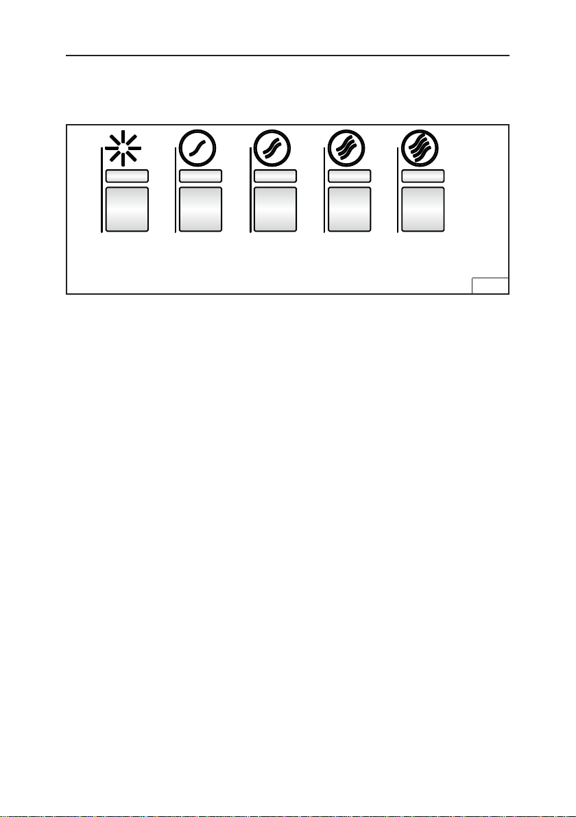
The hood is operated using the (5) push buttons located on the underside of the
hood. Fig. 1.
Lights
On/Low/
High/Off
Ten Minute Delay
Press Blower Speed 1, Blower Speed 2, or Blower Speed 3 for two seconds when
the blower is running at the selected speed. The LED below the button will start
blinking to display the delay function. After ten minutes the blower will automatically
turn off. If you change the speed while the timer is running, the function will not
deactivate. To deactivate the function, press the button with the blinking LED for two
seconds. Note: The delay is not available for Blower Speed 4.
Filter Alarm
After 30 hours of blower operation, the grease filter alarm is activated and all of the
LED indicators will turn on. The alarm is activated when the motor is off and the
LEDs will remain on for 30 minutes. To deactivate the alarm, press any of the control
buttons for two seconds while the LEDs are on.
After 120 hours of blower operation the charcoal filter alarm is activated and all
of the LED indicators will blink, indicating the charcoal filters need to be replaced.
The alarm is activated when the motor is off and the LEDs will remain on for 30
minutes. To deactivate the alarm, press any of the control buttons for two seconds
while the LEDs are on.
HEAT SENTRY™
Your hood is equipped with a HEAT SENTRY™ thermostat. This thermostat is a
device that will turn on or speed up the blower if it senses excessive heat above
the cooking surface.
1) If blower is OFF - it turns blower ON to HIGH speed.
2) If blower is ON at a lower speed setting - it turns blower up to HIGH speed.
When the temperature level drops to normal, the blower will return to its original
setting.
Blower
Speed 1
Blower
Speed 2
Blower
Speed 3
Blower
Speed 4
Fig. 1
WARNING
The HEAT SENTRY™ thermostat can start the blower even if the hood is turned
OFF. When this occurs, it is impossible to turn the blower OFF with its switch.
If you must stop the blower, do it from the main electrical panel.
- 4 -
Page 5
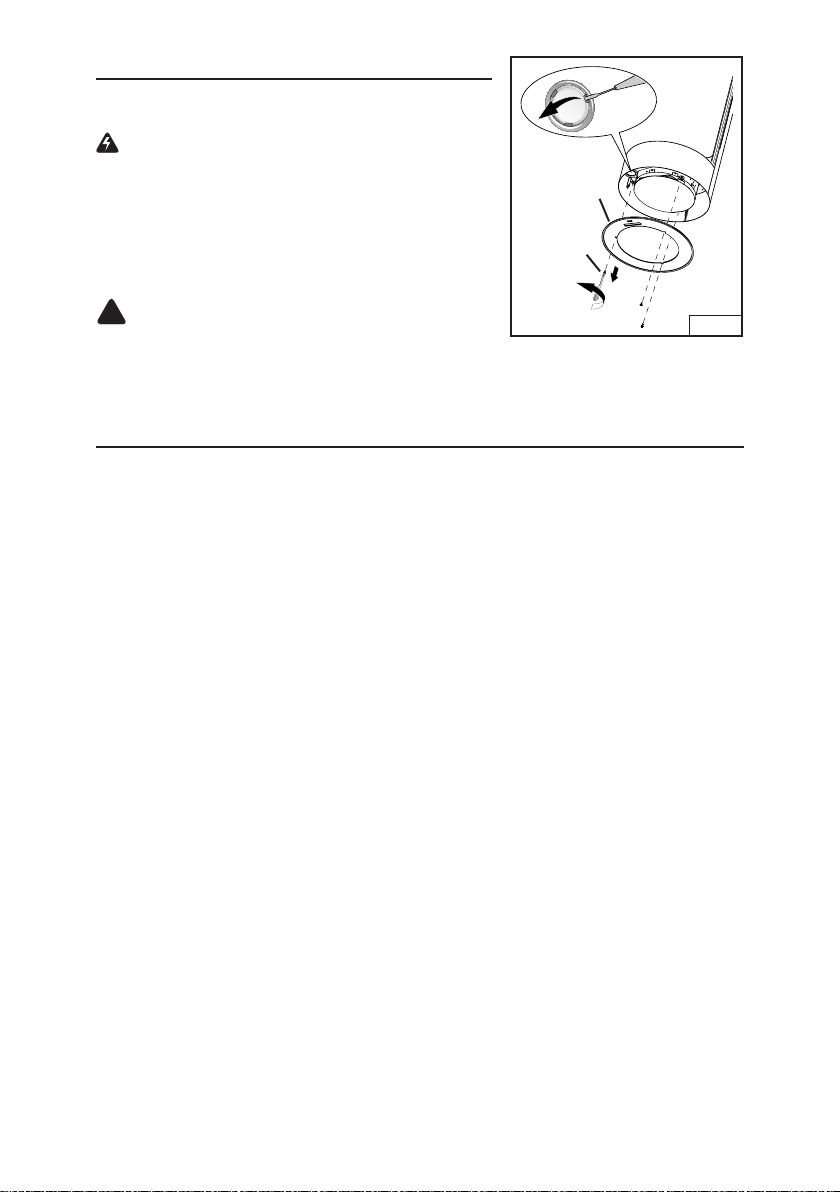
HALOGEN BULBS
!
This range hood requires six halogen bulbs (Type T3,
12 Volt, 20 Watt Max, G4 Base).
WARNING: Always switch off the electrical
supply before carrying out any operation on the
appliance.
To change bulbs:
1. Remove the glass lens by removing the (3) mount-
ing screws. Fig. 2.
GLASS
LENS
MOUNTING
SCREWS
2. Carefully drop down the glass lens without putting
any strain on the control wires.
CAUTION: Bulbs may be hot.
Fig. 2
3. Open the cover by prying from the proper slots. Do
not touch replacement bulbs with bare hands!
4. Replace with Type T3, 12 Volt, 20 Watt Max G4 Base halogen bulbs.
CLEANING AND MAINTENANCE
Proper maintenance of the Range Hood will assure proper performance of the unit.
Motor
The motor is permanently lubricated and never needs oiling. If the motor bearings make
excessive or unusual noise, replace the motor with the exact service motor. The impeller
should also be replaced.
Grease Filters
The grease filters should be cleaned frequently, typically when the filter alarm turns on. Use
a warm dishwashing detergent solution. Grease filter is dishwasher safe.
Clean all-metal filters in the dishwasher using a non-phosphate detergent. Discoloration of
the filter may occur if using phosphate detergents, or as a result of local water conditions
- but this will not affect filter performance. This discoloration is not covered by the warranty.
See “INSTALL FILTERS” section for removal and installation instructions.
Non-ducted Recirculation Filter
The non-ducted recirculation filter should be changed every 6 months. Replace more often if
your cooking style generates extra grease, such as frying and wok cooking. See “INSTALL
FILTERS” section, on page 15, for removal and installation instructions.
Stainless Steel Cleaning
DO:
• Regularly wash with clean cloth or rag
soaked with warm water and mild soap
or liquid dish detergent.
• Always clean in the direction of original
polish lines.
• Always rinse well with clear water (2 or 3
times) after cleaning. Wipe dry completely.
• You may also use a specialized household
stainless steel cleaner.
DON’T:
Use any steel or stainless steel wool or any
•
other scrapers to remove stubborn dirt.
• Use any harsh or abrasive cleansers.
• Allow dirt to accumulate.
• Let plaster dust or any other construction
residues reach the hood. During construction/renovation, cover the range hood to
make sure no dust sticks to the stainless
steel surface.
Avoid: When choosing a detergent
• Any cleaners that contain bleach will attack stainless steel
• Any products containing: chloride, fluoride, iodide, bromide will deteriorate surfaces rapidly.
• Any combustible products used for cleaning such as acetone, alcohol, ether, benzol, etc.,
are highly explosive and should never be used close to a range.
- 5 -
Page 6

PREPARE THE HOOD
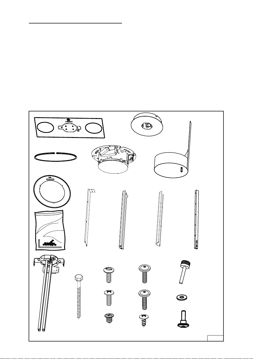
Unpack hood and check contents.
You should receive:
2 - Power Unit
1 - Ceiling Canopy
2 - Decorative Shroud
1 - Telescopic Mounting Arm
2 - Glass Gasket
2 - Glass Trim
2 - Lower Support Arms
2 - Bracket
2 - Upper Arm Cover
2 - Lower Arm Cover
6 - Lag Bolts, M6x60
12 - Washers, 12.5 mm
2 - Large Head Torx Screws, M4x16
2 - Large Head Torx Screws, M4x20
6 - Decorative Step Screws, M4x16
4 - Pan Head Screws, M4x20
6 - Machine Screws, M4x16
12 - Flat Head Screws, M4x6
4 - Black Sheet Metal Screws, M3x13
4 - Thumb Screws, M4x24
2 - Set Screw Kit containing:
12 - M6 Set Screws
1 - Allen Wrench
1 - Mounting Template
1 - Installation Instructions
CEILING CANOPY
MOUNTING TEMPLATE
2 GLASS GASKETS
2 GLASS TRIMS
SET
SCREW
KIT
6 LAG
BOLTS,
M6X60
TELESCOPIC
MOUNTING ARM
2 POWER UNITS
2 BRACKETS
2 LOWER
ARM
COVERS
6 MACHINE
SCREWS,
M4x16
4 PAN HEAD
SCREWS,
M4x20
12 FLAT
HEAD
SCREWS,
M4x6
- 6 -
2 DECORATIVE
SHROUDS
2 UPPER ARM
COVERS
2 LARGE
HEAD TORX
DRIVE
SCREWS,
M4x16
2 LARGE
HEAD TORX
DRIVE
SCREWS,
M4x20
4 BLACK
SHEET METAL
SCREWS,
M3x13
2 LOWER
SUPPORT
ARMS
4 THUMB
SCREWS,
M4x24
12 WASHERS,
12.5 MM
6 DECORATIVE
STEP SCREWS,
M4x16
Fig. 3
Page 7
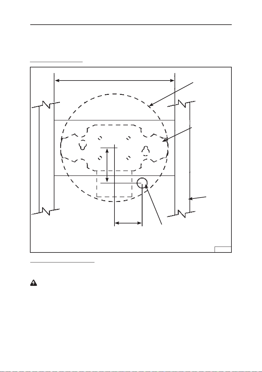
STRUCTURAL REQUIREMENTS
The total weight of the hood is 100 lbs. as supplied. Special structure considerations must be made to ensure proper installation. The mounting brackets need to
be mounted to 2" nominal lumber. Hollow wall anchors should not be used at any
time. Fig. 4.
ROUGH-IN DETAILS
3-1/2"
12"
2-3/4"
OUTLINE
OF CEILING
CANOPY
2X 6 BLOCKING
(MIN.) MUST BE
FLUSH WITH
CEILING JOISTS
2X 4
FRAMING
INCOMING
POWER
LOCATION
Fig. 4
ROUGH-IN ELECTRICAL
This hood is hard wired via a junction box located in the hood canopy. Incoming
power should be located as shown on the drawings above.
WARNING: Electrical wiring must be done by a qualified person in accor-
dance with all applicable codes and standards.
- 7 -
Page 8
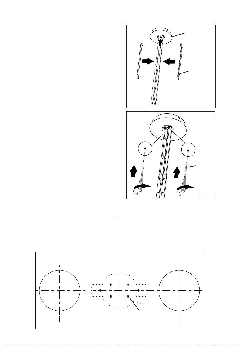
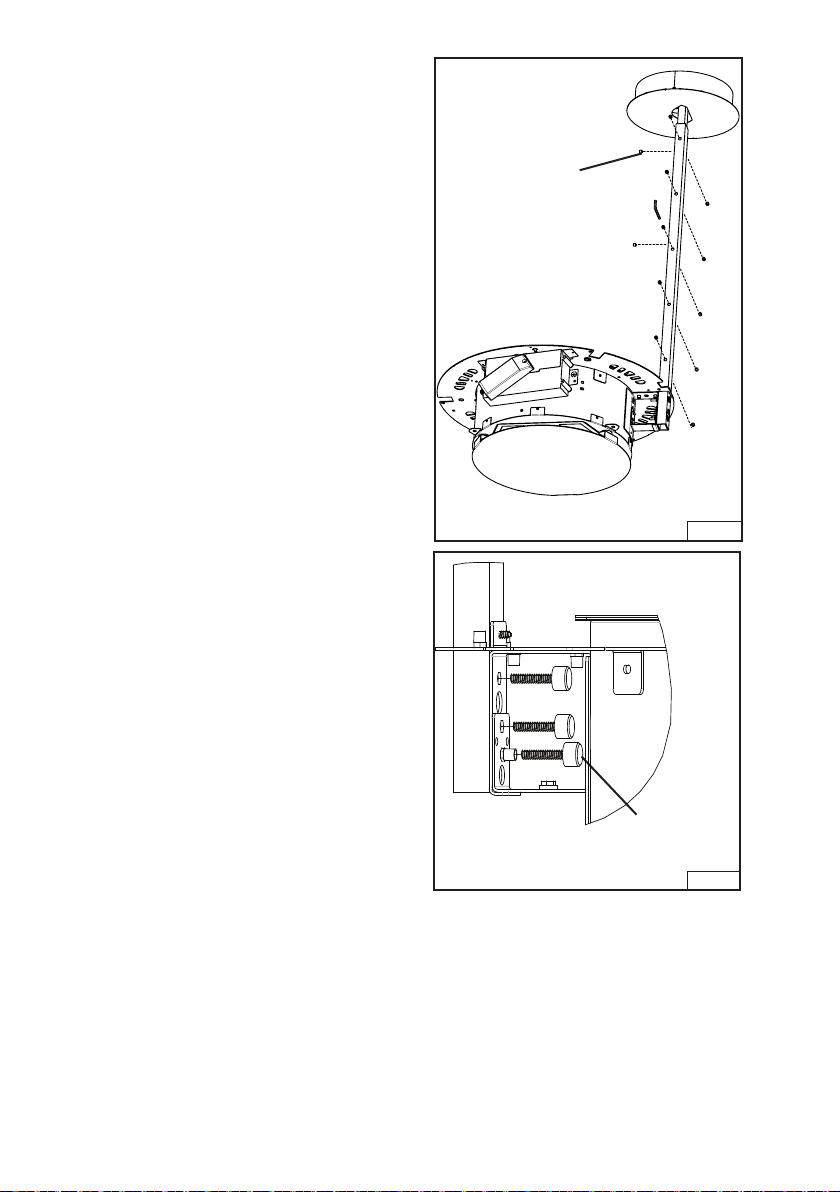
INSTALL UPPER BRACKETS
Note: Covers mount between the
telescopic arm and mount on the
ceiling bracket.
1. Install the Upper Brackets to the
Telescopic Mounting Arm using
(2) Large Head M4x 20 Torx drive
screws. Fig. 5 and Fig. 6. Remove the
protective coating.
COVER
UPPER
BRACKETS
Fig. 5
M4x 20
TORX
DRIVE
SCREWS
MOUNT TELESCOPIC
MOUNTING ARMS
1. Tape the mounting template in place
and drill (6) 1/8" (3 mm) diameter
holes at the center locations shown.
Fig. 7. When complete remove template from ceiling.
Fig. 6
1/8" DIAMETER
LOCATIONS (6)
Fig. 7
- 8 -
Page 9
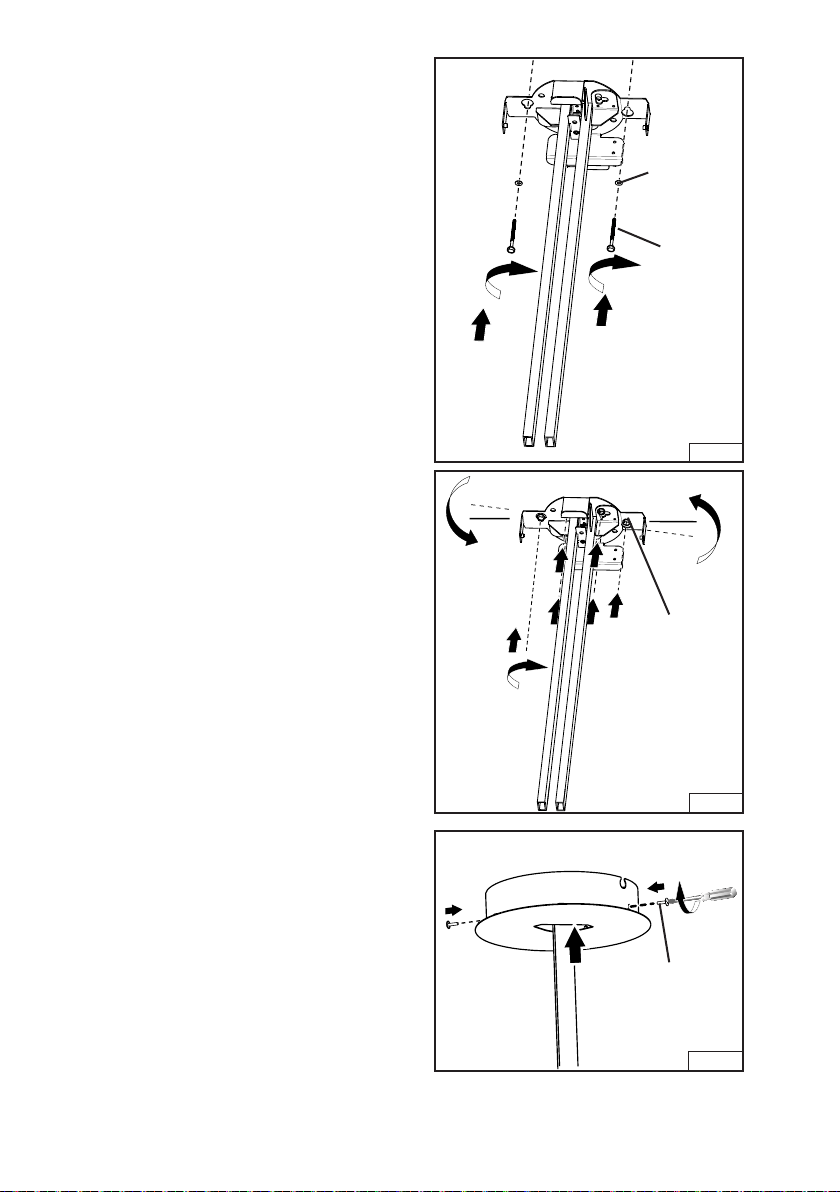
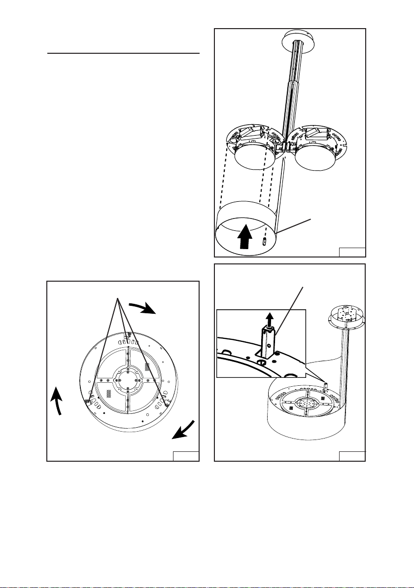
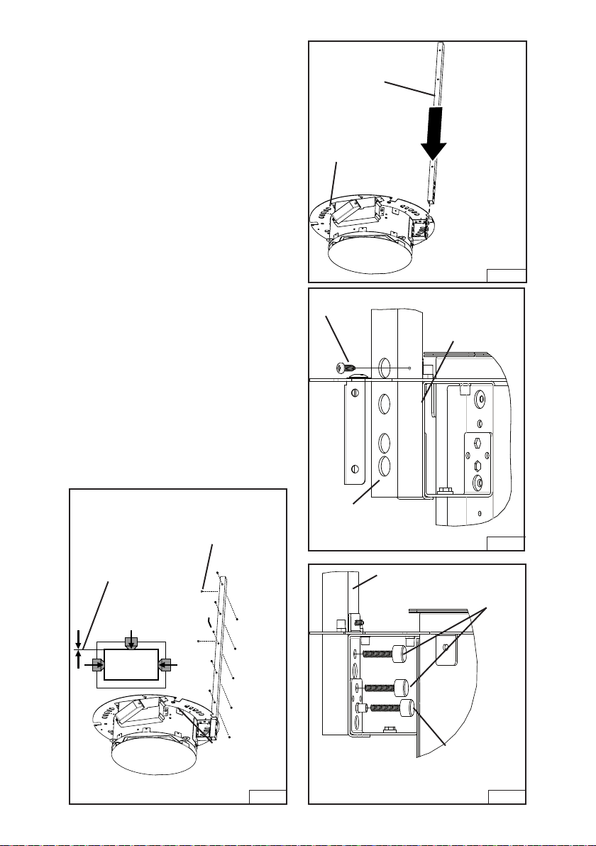
2. Mount the telescopic arm. Attach with
(2) M6 x 60 lag bolts with (2) 12.5 mm
washers - mount the two key hole
slots first (2 bolts / arm). Make sure
the arms are perpendicular to the
ceiling. Fig. 8.
3. Attach the remaining four (4) M6x60
lag bolts per arm. Fig. 9.
4. Install the ceiling canopy and attach
with (2) M4 x 16 large head torx
drive screws. Fig. 10. (You will need
to remove it when making electrical
connections.)
12.5 MM
WASHERS
M6X60
LAG
BOLTS
Fig. 8
M6X60
LAG
BOLTS
- 9 -
Fig. 9
M4X16 LARGE
HEAD
TORX DRIVE
SCREWS (2)
Fig. 10
Page 10
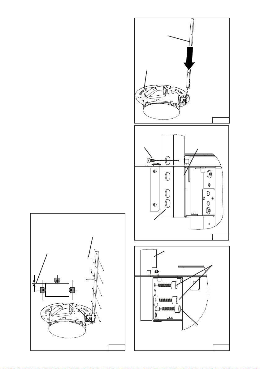
5. Attach the lower support arms to each
power unit. Slide the support arm
through the slot in power unit flange.
Fig. 11.
6. Attach the arm to the power unit
flange with (1) M3 x 13mm sheet
metal screw. Fig. 12.
7. Continue to attach arm to power unit
with (2) M4 x 24mm thumb screws.
Attach a third M4 x 24mm thumb
screw to the threaded insert in the
power unit flange. This screw will be
used to level the power unit later .
Fig. 13.
8. Insert 12 set screws into each lower
support arm. Make sure the screws
do not protrude into the inner section
of the arm. Fig. 14.
LOWER
SUPPORT
ARM
POWER
UNIT
FLANGE
M3 x 13
SHEET
METAL
SCREW
Fig. 11
POWER
UNIT
FLANGE
NOTE: SET
SCREWS
SHOULD NOT
PROTRUDE
SET
SCREWS
(12)
Fig. 14
- 10 -
SUPPORT
ARM
SUPPORT
ARM
Fig. 12
THUMB
SCREW
LEVELING
THUMB
SCREW
Fig. 13
Page 11
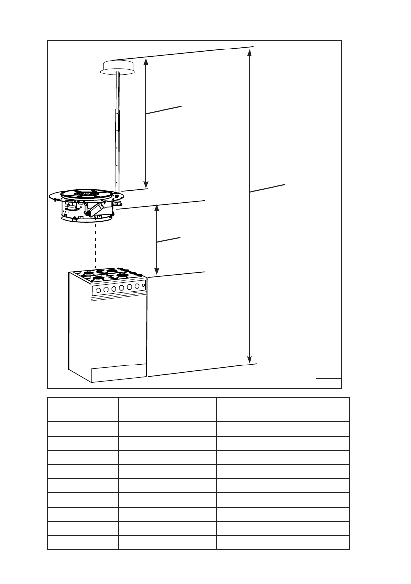
9. Determine mounting height.
ASSEMBLED
TELESCOPIC
ARM HEIGHT
CEILING
HEIGHT
COOKTOP TO
BOTTOM HOOD
DISTANCE
Ceiling Height
Distance Cooktop to
Bottom of Hood
Height of assembled telescopic
arm assembly
8 ft 24" 33.25"
8 ft 25” 32.25”
8 ft 26" 31.25"
8 ft 27" 30.25"
9 ft 24" 45.25"
9 ft 26" 43.25"
9 ft 28" 41.25"
9 ft 29” 40.25”
9 ft 30" 39.25"
- 11 -
Fig. 15
Page 12
10. Install the lower support arm onto the
upper arm at the desired mounting
height. Tighten the set screws making sure at least (5) screws are in
contact with the upper arm. Fig. 16.
Repeat for the second unit.
11. Level the two units with the cook
top surface using the leveling thumb
screw. Fig. 1 7.
SET
SCREWS
Fig. 16
- 12 -
LEVELING
THUMB
SCREW
Fig. 17
Page 13
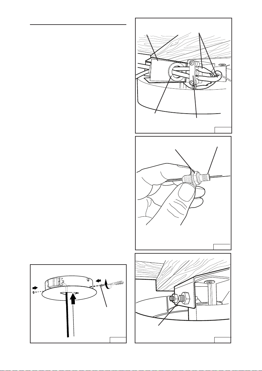
INSTALL WIRING
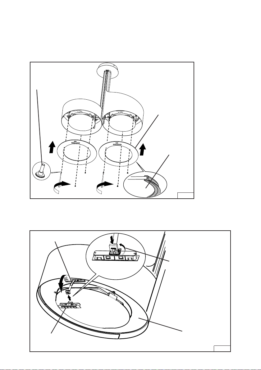
1. Drop the ceiling canopy. Wire tie the
two power cables to the support
arms. Insert the wires onto the strain
relief and into the junction box. Secure the wires by tightening the strain
relief. Make the power connections
Fig. 18.
2. Feed the wire safety cables along the
support arms and insert into the cable
supports as shown in Fig. 19. Repeat
for each power unit.
A. Push cable through support rods
and into hood cavity.
B. Slide washer and cable clamp
with barrel nut onto cable. Note
that the barrel nut must be slightly
backed off of cable clamp and
pushed (spring compressed)
when sliding assembly onto cable.
C. Push clamp assembly all the way
to the top of the hood while pushing down on barrel nut. Fig. 19.
D. When assembly is all the way to
the top inside of hood, completely
tighten barrel nut. Fig. 20.
E. Cut excess cable off.
3. Install the ceiling canopy and attach
with (2) M4 x 16 large head torx drive
screws. Fig. 21. Remove the protective coating.
JUNCTION
BOX
WIRE
WAY
GROMMET
HEX NUT
POWER
CABLES
STRAIN
RELIEF
BARREL NUT
Fig. 18
M4 x 16 LARGE
HEAD
TORX DRIVE
SCREWS (2)
Fig. 21
NOTE: CABLE CLAMP ASSEMBLY
INCLUDES BARREL NUT AND HEX NUT.
Fig. 19
CABLE CLAMP
ASSEMBLY
Fig. 20
- 13 -
Page 14
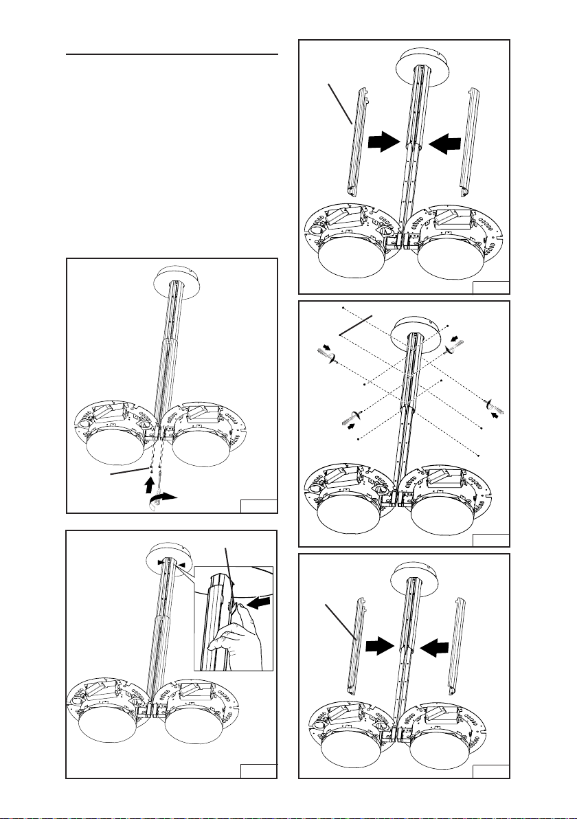
INSTALL ARM COVERS
1. Attach (2) Upper Arm Covers to the
Upper Brackets with (12) M4x6 flat
head screws. Remove the protective
coating. Fig. 22 and Fig. 23.
2. Attach the Lower Arm Covers with (4)
M4x20 pan head screws. Remove
the protective coating. Fig. 24 and
Fig. 25.
3. Bend the two ears on the Lower Arm
Cover over the Upper Arm Cover.
Repeat for the other cover. Fig. 26.
UPPER
ARM
COVERS
Fig. 22
M4X6 FLAT HEAD SCREWS (12)
M4X20
PAN HEAD
SCREWS (4)
EARS
Fig. 25
Fig. 26
Fig. 23
LOWER
ARM
COVERS
Fig. 24
- 14 -
Page 15
INSTALL DECORATIVE
SHROUDS
1. First Slide the Shroud between the
support arms. Make sure the attachment brackets are above the power
unit flange. Fig. 27 and Fig. 28.
2. Turn the Decorative Shroud so that
the shroud holes match up with the
flange holes. Secure the Shroud with
(3) M4x16 machine screws. Fig. 29.
Remove the protective coating.
Repeat for the second shroud.
M4X16 MACHINE SCREWS
SHROUD
Fig. 27
ATTACHMENT BRACKET
Fig. 29
Fig. 28
- 15 -
Page 16
3. Attach the Glass Gasket to the Glass
as shown. Repeat for second glass.
Fig. 30.
4. Pull the control wire thru the glass
opening. Attach the Glass with (3)
M4x 16 Decorative Step Screws.
Fig. 30. Repeat for second glass.
M4X16
DECORATIVE
STEP SCREW
5. Attach the Control Cable to the Con-
trol. Fig. 3 1.
6. Snap the Control into the Decorative
Glass. Fig. 3 1.
GLASS
GASKET
GLASS
FACING
TOWARDS
COOKTOP
Fig. 30
CONTROL
CABLE
CONTROL
PUSH CONNECTOR DOWN
INTO
CONTROL AND
SNAP INTO PLACE
DECORATIVE
GLASS
Fig. 31
- 16 -
Page 17
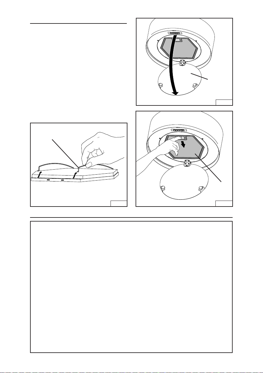
INSTALL FILTERS
1. Remove the filter; remove any protec-
tive coatings on the filters.
A. Swing filter cover down. Fig. 32.
B. Remove filter by pushing tab in
and swing the filter down. Fig. 33.
C. Remove the charcoal filter by
removing the wire holders from
the main filter. Fig. 34.
2. Repeat step 1 and replace the filters.
3. Remove all protective coverings from
the hood.
WIRE
HOLDER
FILTER
COVER
Fig. 32
FILTER
Fig. 34
Fig. 33
WARRANTY
Broan-NuTone LLC (Broan-NuTone) warrants to the original consumer purchaser of Best products that such products
will be free from defects in materials or workmanship for a period of one year from the date of original purchase. THERE
ARE NO OTHER WARRANTIES, EXPRESS OR IMPLIED, INCLUDING, BUT NOT LIMITED TO, IMPLIED WARRANTIES OR MERCHANT ABILITY OR FITNESS FOR A PARTICULAR PURPOSE.
During this one-year period, Broan-NuTone will, at its option, repair or replace, without charge, any product or part which
is found to be defective under normal use and service.
THIS WARRANTY DOES NOT EXTEND TO FLUORESCENT LAMP STARTERS, TUBES, HALOGEN AND INCANDESCENT BULBS, FUSE, FILTERS, DUCTS, ROOF CAPS, WALL CAPS AND OTHER ACCESSORIES FOR DUCTING.
This warranty does not cover (a) normal maintenance and service or (b) any products or parts which have been subject
to misuse, negligence, accident, improper maintenance or repair (other than by Broan-NuTone), faulty installation or
installation contrary to recommended installation instructions.
The duration of any implied warranty is limited to the one-year period as specified for the express warranty. Some states
do not allow limitation on how long an implied warranty lasts, so the above limitation may not apply to you.
BROAN-NUTONE’S OBLIGATION TO REPAIR OR REPLACE, AT BROAN-NUTONE’S OPTION, SHALL BE THE
PURCHASER’S SOLE AND EXCLUSIVE REMEDY UNDER THIS WARRANTY. BROAN-NUTONE SHALL NOT BE LIABLE FOR INCIDENTAL, CONSEQUENTIAL OR SPECIAL DAMAGES ARISING OUT OF OR IN CONNECTION WITH
PRODUCT USE OR PERFORMANCE. Some states do not allow the exclusion or limitation of incidental or consequential
damages, so the above limitation or exclusion may not apply to you.
This warranty gives you specific legal rights, and you may also have other rights, which vary from state to state. This
warranty supersedes all prior warranties.
To qualify for warranty service, you must (a) notify Broan-NuTone at the address stated below or telephone number stated
below, (b) give the model number and part identification and (c) describe the nature of any defect in the product or part.
At the time of requesting warranty service, you must present evidence of the original purchase date.
In USA - Best®, 926 W. State Street, Hartford, WI 53027 (800-558-1711)
In Canada - Best®, 550 Lemire Blvd., Drummondville, QC J2C 7W9 (866-737-7770)
www.BestRangeHoods.com
ONE YEAR LIMITED WARRANTY FOR BEST PRODUCTS
- 17 -
Page 18
SERVICE PARTS
KEY NO. PART NO. DESCRIPTION
1 B08092783 FRAME
5 B03115221 GRILL
9 B08087691 GREASE FILTER
14 B02300976 CONDENSER
26 B02300891 LAMP BULB
37 B02300804 KNOB
38 B03292357 ELECTRICAL CIRCUIT BOARD BOX
39 B03294033 ELECTRICAL CIRCUIT BOARD BOX COVER
48 B02310731 MOTOR (CLOCKWISE)
50 B03294349 BLOWER BRACKET
53 B03204177 RUBBER WASHER
76 B02005214 TOP GLASS
11 4 B03292499 RUNNER WIRES
11 5 BE3348996 FEEDER CABLE CONNECTION BOX
11 6 BE3334252 FEEDER CABLE CONNECTION BOX COVER
11 8 BE3350690 BOTTOM DUCT EXT.
11 9 BE3350691 UPPER DUCT EXT.
124 B02011387 BOTTOM TELESCOPIC SKELETON
125 B08093200 UPPER TELESCOPIC SKELETON
144 B03292287 WIRES STOP PIN
151 B032920200 ELECTRICAL BOX WIRES STOP
154 B03202286 FEEDER CABLE STOP
195 BE3350719 BRACKET
202 B03292290 REFLECTOR STOP
208 B02300861 TRANSFORMER
312 B08092785 INSIDE PANEL
332 B08093199 COVER
362 B02011377 DISPLAY VISOR SPRING
415 B03202291 FAIRLEAD
B03202442 FAIRLEAD
B03299169 FAIRLEAD
474 B02300798 HALOGEN LAMP
477 B02011376 CLOSING
AQI B06108625 SWITCH BOX ASSEMBLY
* B06103994 CONDENSER ASSEMBLY
(INCLUDES KEY NO. 14, 38, 39, 151)
* B06145147 ELECTRICAL INSTALLATION ASSEMBLY
(INCLUDES KEY NO. 14, 38, 39,
60, 67, 144, 151, 166, 208)
* B080810953 FITTING SET (INCLUDES KEY NO. 154)
- 18 -
Page 19

SERVICE PARTS
60
115
116
202
415 (03202169)
151
415 (03202442)
208
14
39
144
166
38
67
AQI
114
415 (03202291)
474
26
50
9
37
477
312
124
125
195
119
118
154
332
5
53
48
362
76
1
Fig. 35
- 19 -
Page 20

- 20 -
99044741A
Page 21

Modèle IM32I100SP
ENGLISH ................................... 2
FRANÇAIS ................................ 21
ESPAÑOL.................................. 41
Aux ÉTATS-UNIS - BEST Hartford, Wisconsin
Au CANADA - BEST Drummondville, QC, Canada
ENREGISTREZ VOTRE PRODUIT EN LIGNE À L’ADRESSE: www.BestRangeHoods.com/register
Pour en savoir plus, visitez le site www.BestRangeHoods.com
- 21 -
Page 22

VEUILLEZ LIRE ET CONSERVER CES INSTRUCTIONS
!
!
CONÇUE POUR LES CUISINES PRIVÉES UNIQUEMENT
AVERTISSEMENT
POUR RÉDUIRE LES RISQUES D’INCENDIE, D’ÉLECTROCUTION OU DE BLESSURES
PHYSIQUES, RESPECTEZ LES INSTRUCTIONS CI-DESSOUS :
1. Utilisez cet appareil uniquement de la manière prévue par le fabricant. Si vous avez des
questions, contactez le fabricant à l’adresse ou au numéro de téléphone indiqués dans la
garantie.
2. Avant d’effectuer l’entretien ou le nettoyage de l’appareil, mettez-le hors tension sur le panneau de service et verrouillez ce dernier pour éviter que l’appareil soit mis sous tension par
inadvertance. S’il n’est pas possible de verrouiller le dispositif de déconnexion, apposez un
avertissement bien visible (par exemple une étiquette) sur le panneau de service.
3. L’installation et le raccordement électrique doivent être effectués par du personnel qualifié
conformément à toutes les réglementations et normes en vigueur, y compris celles concernant
les constructions cotées pour leur résistance au feu.
4. Afin d’éviter un refoulement lors de l’utilisation d’équipements à combustible, une quantité
d’air suffisante est nécessaire pour assurer une combustion et un échappement adéquats
des gaz à travers le conduit (la cheminée). Suivez les consignes du fabricant de l’équipement
chauffant et les normes de sécurité publiées, entre autres, par la National Fire Protection
Association (NFPA) et l’American Society for Heating, Refrigeration and Air Conditioning
Engineers (ASHRAE), ainsi que les réglementations locales.
5. Quand vous effectuez une découpe ou un forage dans un mur ou un plafond, veillez à ne
pas endommager des câblages électriques ou d’autres équipements non visibles.
6. Les soufflantes canalisées doivent toujours être dirigées vers l’extérieur.
7. N’utilisez pas cet appareil avec un dispositif de commande de vitesse transistorisée séparé.
8. Pour réduire les risques d’incendie, utilisez uniquement des canalisations en métal.
INSTRUCTIONS DE MISE À LA TERRE
Cet appareil doit être mis à la terre. En cas de court-circuit électrique, la mise à la terre réduit le
risque d’électrocution grâce à un fil permettant au courant électrique de s’échapper. Cet appareil
est doté d’un cordon ayant un fil de terre, ainsi que d’une fiche de mise à la terre. La fiche doit
être branchée dans une prise bien installée et mise à la terre.
AVERTISSEMENT - Une mise à la terre inappropriée peut donner lieu à un risque d’électrocution.
Consultez un électricien qualifié si vous ne comprenez pas parfaitement les instructions de
mise à la terre ou si vous n’êtes pas certain(e) que l’appareil est mis à la terre comme il se doit.
N’utilisez pas de rallonge. Si le cordon est trop court, demandez à un électricien d’installer une
prise près de l’appareil.
- 22 -
Page 23

!
AVERTISSEMENT
POUR RÉDUIRE LE RISQUE D’UN FEU DE FRITURE SUR LA TABLE DE CUISSON
A. Ne laissez jamais les appareils de surface sans surveillance quand ils sont sur un réglage élevé.
Les débordements peuvent provoquer de la fumée et des déversements gras risquant de prendre
feu. Chauffez les huiles lentement sur un réglage bas ou moyen.
B. Allumez toujours la hotte quand vous cuisinez à une chaleur élevée ou quand vous flambez des
aliments (p. ex. des crêpes Suzette, des cerises jubilé ou du bœuf au poivre flambé).
C. Nettoyez souvent les ventilateurs d’aération. Évitez que la graisse ne s’accumule sur le ventilateur
ou le filtre.
D. Utilisez des poêles de la taille appropriée. Utilisez toujours des ustensiles de cuisine adaptés à la
taille de l’élément de surface.
POUR RÉDUIRE LE RISQUE DE BLESSURES PHYSIQUES EN CAS DE FEU DE FRITURE SUR
LA TABLE DE CUISSON, VEUILLEZ PROCÉDER COMME SUIT:*
1. ÉTOUFFEZ LES FLAMMES avec un couvercle hermétique, une plaque à biscuits ou un plateau
en métal, puis éteignez le brûleur. SOYEZ PRUDENT(E) AFIN D’ÉVITER LES BRÛLURES. Si les
flammes ne s’éteignent pas immédiatement, ÉVACUEZ LES LIEUX ET APPELEZ LE SERVICE
DES POMPIERS.
2. NE SAISISSEZ JAMAIS UNE POÊLE ENFLAMMÉE, vous risquez de vous brûler.
3. N’UTILISEZ JAMAIS D’EAU ni de torchons ou serviettes mouillé(e)s : cela donnerait lieu à une
violente explosion de vapeur.
4. Utilisez un extincteur UNIQUEMENT si:
A. Vous savez qu’il s’agit d’un extincteur de Classe ABC et savez déjà comment vous en servir.
B. L’incendie est de petite taille et confiné à l’endroit où il a commencé.
C. Le service des pompiers a été averti.
D. Vous pouvez éteindre l’incendie en ayant une sortie derrière vous.
* Basé sur «Kitchen Fire Safety Tips», publié par la NFPA.
ATTENTION
1. Uniquement pour l’utilisation intérieure.
2. Pour réduire le risque d’incendie et obtenir un échappement d’air adéquat, veillez à bien canaliser
l’air vers l’extérieur. Ne ventilez pas l’air d’échappement vers des espaces confinés, des plafonds,
des combles, des vides sanitaires ou des garages.
3. Soyez prudent(e) quand vous utilisez des agents de nettoyage ou des détergents.
4. Évitez d’utiliser sous la hotte de cuisine des denrées alimentaires produisant des flammes.
5. À utiliser uniquement pour la ventilation générale. N’utilisez pas la hotte pour l’échappement de
matériaux ou de vapeurs comportant un danger ou un risque d’explosion.
6. Pour éviter que le roulement moteur s’endommage et que des hélices deviennent bruyantes ou
déséquilibrées, faites en sorte que le bloc d’alimentation n’entre pas en contact avec un atomiseur
pour cloisons sèches, de la poussière de construction, etc.
7. Le moteur de la hotte est doté d’un rupteur thermique qui éteint automatiquement le moteur en
cas de surchauffe. Le moteur redémarrera après avoir refroidi. Si le moteur s’éteint et se rallume
constamment, faites réparer la hotte.
8. Pour mieux capturer les impuretés de cuisson, la partie inférieure de la hotte doit se trouver au
minimum à 60cm (24 po) et au maximum à 75cm (30 po) au-dessus de la surface de cuisson.
Consultez la section «Installation du support de montage» pour connaître les restrictions de
montage.
9. Étant donné la taille et le poids de la hotte, il est conseillé d’avoir recours à deux personnes pour
la monter.
10. Ce produit est doté d’un thermostat qui peut activer la soufflante automatiquement. Pour éviter les
risques de blessure et l’allumage accidentel de la hotte, mettez-la hors tension sur le panneau de
service et verrouillez ce dernier ou fixez-y une étiquette d’avertissement.
11. Pour en savoir plus et connaître les exigences sur le produit, veuillez lire l’étiquette des spécifications.
- 23 -
Page 24

FONCTIONNEMENT
Commandes
La hotte s’utilise à l’aide des (5)boutons-poussoirs situés sous la hotte. Fig. 1.
Lumières
allumées/
Vitesse de
soufflante 1
Vitesse de
soufflante 2
Vitesse de
soufflante 3
Vitesse de
soufflante 4
basses/
hautes/
éteintes
Temporisation de dix minutes
Appuyez sur Vitesse 1, Vitesse de soufflante 2 ou 3 pendant deux secondes lorsque la
soufflante fonctionne à la vitesse choisie. La DEL sous le bouton commencera à clignoter
pour afficher la fonction de temporisation. Après dix minutes, la soufflante s’éteindra
automatiquement. Si vous changez de vitesse tandis que la minuterie est en marche, la
fonction ne se désactivera pas. Pour désactiver la fonction, appuyez sur le bouton avec la
DEL clignotante pendant deux secondes. Remarque: la temporisation n’est pas disponible
pour la vitesse 4 de la soufflante.
Alarme du filtre
Après 30 heures de fonctionnement de la soufflante, l’alarme du filtre s’active et tous les
voyants DEL s’allument. L’alarme s’active lorsque le moteur est éteint et les DEL resteront
en marche pendant 30 minutes. Pour désactiver l’alarme, appuyez l’un des boutons de
contrôle pendant deux secondes tandis que les DEL sont en marche.
Après 120 heures de fonctionnement de soufflante, l’alarme du filtre à charbon est activée
et tous les indicateurs DEL clignoteront indiquant que les filtres à charbon devraient être
changés. L’alarme s’active lorsque le moteur est éteint et les DEL resteront en marche
pendant 30 minutes. Pour désactiver l’alarme, appuyez l’un des boutons de contrôle pendant
deux secondes tandis que les DEL sont en marche.
HEAT SENTRY™
La hotte est équipée d’un thermostat HEAT SENTRY™. Ce dispositif active ou accélère la
soufflante s’il détecte une chaleur excessive au-dessus de la surface de cuisson.
1) Si la soufflante est arrêtée, il l’allume sur la vitesse HAUTE.
2) Si la soufflante est allumée à une vitesse basse, il la fait passer à la vitesse HAUTE.
Quand la température redevient normale, la soufflante retourne au réglage d’origine.
Fig. 1
AVERTISSEMENT
Le thermostat HEAT SENTRY™ peut activer la soufflante même si la hotte est éteinte.
Dans ce cas, il est impossible de désactiver la soufflante avec le commutateur d’arrêt.
Si vous devez arrêter la soufflante, faites-le depuis le panneau électrique principal.
- 24 -
Page 25

AMPOULES HALOGÈNES
!
Cette hotte de cuisine nécessite six ampoules halogènes (TypeT3,
12V, 20W max., base G4).
AVERTISSEMENT: Désactivez toujours l’alimentation
avant d’effectuer toute opération sur l’appareil.
Pour changer les ampoules:
1. Retirez la lentille de verre en dévissant les (3) vis de montage.
Fig. 2.
2. Déposez avec soin la lentille de verre sans imposer aucune
tension sur les fils de contrôle.
ATTENTION: Il est possible que les ampoules soient
chaudes.
3. Ouvrez le couvercle en faisant levier sur les fentes prévues àcet
effet. Ne touchez pas les ampoules de rechange à mains nues!
4. Remplacez par des ampoules halogènes de Type T3, 12V, 20 watts max à base G4.
LENTILLES
DU VERRE
VIS DE
MONTAGE
Fig. 2
NETTOYAGE ET ENTRETIEN
Pour assurer les performances de l’appareil, entretenez-le de manière appropriée.
Moteur
Le moteur est lubrifié en permanence et aucun graissage n’est nécessaire. Si les roulements du moteur font
un bruit excessif ou inhabituel, remplacez le moteur par une pièce de rechange identique. Remplacez aussi
les hélices.
Filtres à graisse
Le filtre à graisse devrait être nettoyé fréquemment, normalement lorsque l’alarme du filtre se déclenche.
Utilisez une solution détergente chaude. Le filtre à graisse peut être mis dans le lave-vaisselle.
Nettoyez tous les filtres en métal dans le lave-vaisselle avec un détergent sans phosphate. Si vous utilisez
un détergent phosphaté ou selon le type d’eau, il est possible que le filtre se décolore, mais cela n’affectera
aucunement ses performances. Cette décoloration n’est pas couverte par la garantie.
Consultez la section «INSTALLATION DES FILTRES» pour connaître les instructions de retrait et d’installation.
Filtre de recirculation non canalisé
Le filtre de recirculation non canalisé doit être changé tous les 6 mois. Si votre style de cuisine engendre
beaucoup de graisse, par exemple si vous faites souvent de la friture ou utilisez un wok, remplacez-le plus
souvent. Consultez la section «INSTALLATION DES FILTRES» de la page 15 pour connaître les instructions
de retrait et d’installation.
Nettoyage de l’acier inoxydable
À FAIRE:
• Nettoyez régulièrement l’acier inoxydable avec un
chiffon ou un torchon enduit d’eau chaude et de
savon doux ou de liquide vaisselle.
• Nettoyez toujours dans le sens des lignes de
polissage d’origine.
• Rincez toujours à l’eau claire (2 ou 3fois) après
le nettoyage. Essuyez complètement.
• Vous pouvez aussi utiliser un nettoyant spécial
pour acier inoxydable d’électroménagers.
À éviter : Quand vous choisissez un détergent
• Tous les produits de nettoyage contenant de l’eau de Javel attaquent l’acier inoxydable.
• Tous les produits contenant du chlore, du fluor, de l’iode ou du bromure provoquent une détérioration rapide
des surfaces.
• Tous les produits combustibles utilisés pour le nettoyage, tels que l’acétone, l’alcool, l’éther, le benzène
sont extrêmement explosifs et ne doivent jamais être employés à proximité d’une table de cuisson.
À NE PAS FAIRE:
• N’utilisez pas de laine d’acier inoxydable ni
d’autres racloirs pour enlever la saleté difficile à
éliminer.
• N’utilisez pas de produits de nettoyage durs ou
abrasifs.
• Ne laissez pas la poussière s’accumuler.
• Maintenez la hotte à l’abri de la poussière de plâtre
ou d’autres résidus de construction. Pendant la
construction/les rénovations, couvrez la hotte
afin d’éviter qu’aucune poussière n’adhère aux
surfaces en acier inoxydable.
- 25 -
Page 26

PRÉPARATION DE LA HOTTE
Déballez la hotte et vérifiez le contenu de
l’emballage.
Il doit comprendre:
2 - Bloc d’alimentation
1 - Pavillon de plafond
2 - Déflecteur décoratif
1 - Bras de montage télescopique
2 - Joint d’étanchéité de verre
2 - Garniture de verre
2 - Bras de support inférieurs
2 - Support
2 - Housse de bras supérieur
2 - Housse de bras inférieur
6 - Tire-fonds, M6 x 60
12 - Rondelles, 12,5 mm (1/2 po)
2 - Vis à six grands lobes, M4 x 16
2 - Vis à six grands lobes, M4 x 20
6 - Vis d’échelle décoratives, M4 x 16
4 - Vis à tête cylindrique, M4 x 20
6 - Vis à métaux, M4 x 16
12 - Vis à tête fraisée, M4 x 6
4 - Vis autotaraudeuses noires, M3 x 13
4 - Vis à oreilles, M4 x 24
2 - Trousse à vis contenant:
12 - Vis de blocage M6
1 - Clé Allen
1 - Modèle de montage
1 - Instructions d’installation
PAVILLON DE PLAFOND
MODÈLE DE MONTAGE
2 JOINTS D’ÉTANCHÉITÉ
DE VERRE
2 GARNITURES
DE VERRE
TROUSSE
À VIS
6 TIRE-FONDS,
M6 x 60
BRAS DE MONTAGE
TÉLESCOPIQUE
2 BLOCS
D’ALIMENTATION
2 SUPPORTS
2 HOUSSES
DE BRAS
INFÉRIEURS
6 VIS À
MÉTAUX,
M4 x 16
4 VIS À TÊTE
CYLINDRIQUE,
M4 x 20
12 VIS
À TÊTE
FRAISÉE,
M4 x 6
- 26 -
2 DÉFLECTEURS
DÉCORATIFS
2 HOUSSES
DE BRAS
SUPÉRIEURS
2 VIS À SIX
GRANDS
LOBES,
M4 x 16
2 VIS À SIX
GRANDS
LOBES,
M4 x 20
4 VIS
AUTOTARAUDEUSES
NOIRES,
M3 x 13
2 BRAS DE
MONTAGE
INFÉRIEURS
4 VIS À
OREILLES,
M4x24
12 RONDELLES,
12,5 mm (1/2 po)
6 VIS D’ÉCHELLE
DÉCORATIVES,
M4 x 16
Fig. 3
Page 27

EXIGENCES STRUCTURALES
Le poids total de la hotte fournie est de 45,4 kg (100 lb). Il faut tenir compte de considérations structurales spéciales pour assurer une installation appropriée. Les supports de
montage doivent être montés sur un bois d’œuvre nominal de 5 cm (2 po). Les ancrages
muraux creux de toute sorte ne doivent pas être utilisés. Fig. 4.
DÉTAILS BRUTS
30,5 cm (12 po)
8,89cm
(3 1/2 po)
6,98cm
(23/4 po)
CONTOUR DE
PAVILLON DE
PLAFOND
5,08 x 15,24 cm
(2 x 6 po)
BLOCAGE (MIN.)
DOIT AFFLEURER
AVEC LES
SOLIVES DE
PLAFOND
5,08 x 10,16cm
(2 x 4 po)
CADRAGE
SITE D’ENTRÉE
DE COURANT
Fig. 4
ÉLECTRICITÉ BRUTE
Cette hotte est câblée par une boîte de jonction qui se trouve dans le pavillon de hotte.
Lecourant d’entrée devrait se trouver à l’endroit indiqué dans les dessins plus haut.
AVERTISSEMENT : Le câblage électrique doit être réalisé par une personne
qualifiée, conformément aux réglementations et normes en vigueur.
- 27 -
Page 28

INSTALLEZ LES SUPPORTS SUPÉRIEURS
Remarque: les housses se montent
entre le bras télescopique et sur le
support de plafond.
1. Installez les supports supérieurs les bras
de montage télescopique en utilisant (2)
vis à six grands lobes M4x20. Fig. 5 et
Fig. 6. Retirez le revêtement protecteur.
COUVERCLE
SUPPORTS
SUPÉRIEURS
Fig. 5
M4x 20
VIS À SIX
LOBES
MONTEZ LES BRAS DE
MONTAGE TÉLESCOPIQUE
1. Collez le modèle de montage en place et
percez (6) trous de 3 mm (1/8 po) de diamètre aux sites centraux illustrés. Fig.7.
À la fin, retirez le modèle du plafond.
125 MM (1/8 PO)
DE DIAMÈTRE
SITES (6)
- 28 -
Fig. 6
Fig. 7
Page 29

2. Montez le bras télescopique. Fixez avec
les (2) tire-fonds M6x60 avec (2) rondelles de 12,5mm - faites d’abord les deux
fentes de trous de serrure (2 boulons/
bras). Assurez-vous que les bras sont
perpendiculaires au plafond. Fig 8.
3. Fixez les quatre (4) autres tire-fonds
M6X60 restants par bras. Fig. 9.
4. Installez l’auvent de plafond et attachez
avec (2) vis à six grands lobes M4x16.
Fig. 10. (Il faudra le retirer lorsque vous
ferez les connexions électriques.)
12,5 MM
RONDELLES
M6X60
TIREFONDS
Fig. 8
M6X60
TIREFONDS
- 29 -
Fig. 9
M4X16
VIS À SIX
GRANDS LOBES
(2)
Fig. 10
Page 30
5. Attachez les bras de support inférieur à
chaque bloc d’alimentation. Glissez le
bras de support à travers la fente dans
le rebord du bloc d’alimentation. Fig 11.
6. Fixez le bras au rebord du bloc d’alimentation avec (1) vis autotaraudeue
M3x13mm. Fig.12.
7. Continuez à attacher le bras au bloc
d’alimentation avec (2) vis à oreilles
M4x24mm. Fixez une troisième vis à
oreilles M4x24 mm à l’insertion filetée
dans le rebord du bloc d’alimentation.
Cettevis sera utilisée pour niveler le bloc
plus tard. Fig.13.
8. Insérez 12 vis de blocage dans chaque
bras de support inférieur. Assurez-vous
que les vis ne ressortent pas dans la
section inférieure du bras. Fig.14.
BRAS DE
SUPPORT
INFÉRIEUR
COLLERETTE
DE BLOC
D’ALIMENTATION
VIS AUTOTARAUDEUSE
M3 x 13
Fig. 11
COLLERETTE
DE BLOC
D’ALIMENTATION
REMARQUE: SET
VIS DE SERRAGE
NE DEVRAIENT PAS
RESSORTIR
SET
VIS DE SERRAGE
(12)
Fig. 14
BRAS DE SUPPORT
- 30 -
BRAS DE
SUPPORT
Fig. 12
VIS
AUTOTARAUDEUSE
VIS
AUTOTARAUDEUSE
NIVELLANTE
Fig. 13
Page 31

9. Déterminez la hauteur de montage.
ASSEMBLÉ
TELESCOPIC
HAUTEUR DU BRAS
TÉLESCOPIQUE
HAUTEUR DE
PLAFOND
DISTANCE DE
LA SURFACE DE
CUISSON AU BAS
DE LA HOTTE
Fig. 15
Hauteur du
plafond
Distance de la table de
cuisson au bas de la hotte
Hauteur du bras
télescopique assemblé
2,4 m (8 pi) 60cm (24 po) 88,4 cm (33,25 po)
2,4 m (8 pi) 63,5 cm (25 po) 81,3 cm (32,25 po)
2,4 m (8 pi) 66cm (26 po) 79,4 cm (31,25 po)
2,4 m (8 pi) 68,6cm (27 po) 76,8 cm (30,25 po)
2,7 m (9 pi) 60cm (24 po) 114,9 cm (45,25 po)
2,7 m (9 pi) 66cm (26 po) 109,8 cm (43,25 po)
2,7 m (9 pi) 71cm (28 po) 104,7 cm (41,25 po)
2,7 m (9 pi) 73,7 (29 po) 102,2 cm (40,25 po)
2,7 m (9 pi) 75cm (30 po) 99,7 cm (39,25 po)
- 31 -
Page 32

10. Installez le bras de support inférieur
dans le bras supérieur à la hauteur de
montage voulue. Resserrez les vis de
serrage en vous assurant qu’au moins
(5)vis soient en contact avec le bras
supérieur. Fig.16. Répétez pour le
deuxième appareil.
11. Mettez les deux appareils à niveau avec
la surface de la table de cuisson utilisant
la vis autotaraudeuse nivelante. Fig.17.
SET
VIS DE
SERRAGE
Fig. 16
- 32 -
NIVELLANTE VIS
AUTOTARAUDEUSE
Fig. 17
Page 33

INSTALLEZ LE CÂBLAGE
1. Abaissez le pavillon du plafond. Atta-
chez les deux câbles de courant aux
bras de support. Insérez les fils sur le
réducteur de tension et dans la boîte de
jonction. Installez les fils en resserrant
le réducteur de tension. Établissez les
connexions de courant Fig. 18.
2. Acheminez les câbles de sécurité le
long des bras de support et insérez les
supports de câble comme illustré dans
la Fig. 19. Répétez pour chaque bloc
d’alimentation.
A. Poussez le câble à travers les tiges
de support et dans la cavité de la
hotte.
B. Glissez la rondelle et le serre-câble
avec l’écrou sphérique sur le câble.
Notez que l’écrou sphérique doit
être reculé un peu du serre-câble et
poussé (compression à ressort) en
glissant l’assemblage sur le câble.
C. Poussez le serre-câble jusqu’au
dessus de la hotte tout en poussant
vers le bas sur l’écrou sphérique.
Fig. 19.
D. Lorsque l’assemblage est jusqu’au
haut à l’intérieur de la hotte, resserrez entièrement l’écrou sphérique.
Fig. 20.
E. Coupez le surplus de câble.
3. Installez l’auvent de plafond et attachez
avec (2) vis à six grands lobes M4x16.
Fig. 21. Retirez le revêtement protecteur.
BOÎTE DE
JONCTION
PASSE-FIL
OEILLET
ÉCROU
HEXAGONAL
REMARQUE : L’ASSEMBLAGE DU SERRECÂBLE INCLUT L’ÉCROU SPHÉRIQUE ET
L’ÉCROU HEXAGONAL.
CORDONS
D’ALIMENTATION
RÉDUCTEUR
DE TENSION
ÉCROU
SPHÉRIQUE
Fig. 19
Fig. 18
M4 x 16 VIS À SIX
GRANDS LOBES
(2)
Fig. 21
ASSEMBLAGE DU
SERRE-CÂBLE
Fig. 20
- 33 -
Page 34

INSTALLATION DES
HOUSSES DE BRAS
1. Installez les (2) housses de bras su-
périeur aux supports supérieurs avec
(12) vis à tête fraisée M4x6. Retirez le
revêtement protecteur. Fig. 22 et Fig. 23.
2. Attachez les housses de bras inférieur
avec (4) vis à tête cylindrique M4x20.
Retirez le revêtement protecteur. Fig.24
et Fig 25.
3. Repliez les deux oreilles de la housse
du bras inférieur sur la housse du bras
supérieur. Répétez pour l’autre housse.
Fig. 26.
HOUSSE DE
SUPPORTS
SUPÉRIEURS
Fig. 22
M4X6 VIS À TÊTE FRAISÉE (12)
M4 X 20
VIS À TÊTE
CYLINDRIQUE
(4)
OREILLES
Fig. 25
Fig. 26
Fig. 23
HOUSSES
DE BRAS
INFÉRIEUR
Fig. 24
- 34 -
Page 35

INSTALLEZ LES
DÉFLECTEURS DÉCORATIFS
1. Glissez d’abord le déflecteur entre les
bras de support. Assurez-vous que les
supports d’attache sont au-dessus du
rebord du bloc d’alimentation. Fig.27 et
Fig.28.
2. Tournez le déflecteur décoratif pour que
les trous du déflecteur correspondent à
ceux de la collerette. Fixez le déflecteur
avec (3) vis à métaux M4x16. Fig. 29.
Retirez le revêtement protecteur. Répétez pour le deuxième déflecteur.
VIS À MÉTAUX M4 X 16
DÉFLECTEUR
Fig. 27
SUPPORT D’ATTACHE DU DÉFLECTEUR
Fig. 29
Fig. 28
- 35 -
Page 36

3. Attachez le joint d’étanchéité de verre au
verre comme illustré et répétez pour le
deuxième. Fig. 30.
4. Tirez le fil de contrôle à travers l’ouver-
ture de verre. Attachez le verre avec (3)
vis d’échelle décoratives M4x16. Fig30.
Répétez pour le deuxième verre.
M4 X 16
VIS D’ÉCHELLE
DÉCORATIVE
5. Attachez le câble de commande à la
commande. Fig. 3 1.
6. Enclenchez la commande dans le verre
décoratif. Fig. 31.
JOINT
D’ÉTANCHÉITÉ
DU VERRE
VERRE
TOURNÉ
VERS LA
CUISINIÈRE
Fig. 30
CÂBLE DE CONTRÔLE
COMMANDE
ENFONCEZ LE CONNECTEUR
DANS LA COMMANDE ET
ENCLENCHEZ EN PLACE
VERRE DÉCORATIF
Fig. 31
- 36 -
Page 37

INSTALLATION DES FILTRES
1. Retirez le filtre; retirez tous les revête-
ments protecteurs des filtres.
A. Balancez le couvercle du filtre vers
le bas. Fig. 32.
B. Retirez le filtre en enfonçant la lan-
guette et en balançant le filtre vers
le bas. Fig. 33.
C. Retirez le filtre à charbon en retirant
les supports de fils du filtre principal.
Fig. 34.
2. Répétez l’étape 1 et replacez les filtres.
3. Retirez tous les revêtements protecteurs
de la hotte.
SUPPORT DE FILS
COUVERCLE
DU FILTRE
Fig. 32
FILTRE
Fig. 34
Fig. 33
GARANTIE
Broan-NuTone LLC (Broan-NuTone) garantit à l’acheteur consommateur original de produits Best qu’ils sont exempts de vice de
matériaux ou de fabrication pour une période d’un an à compter de la date d’achat original. IL N’Y A PAS D’AUTRES GARANTIES,
EXPRIMÉES OU IMPLICITES, INCLUANT MAIS NON LIMITÉES AUX GARANTIES IMPLICITES DE QUALITÉ MARCHANDE ET
DE CONVENANCE DANS UN BUT PARTICULIER.
Durant cette période d’un an, Broan-NuTone, à sa discrétion, réparera ou remplacera gratuitement tout produit ou pièce qui
s’avèrera défectueux et ayant été utilisé normalement et d’une manière non abusive.
CETTE GARANTIE NE S’APPLIQUE PAS AUX TUBES FLUORESCENTS ET AUX DÉMARREURS, NI AUX AMPOULES
HALOGÈNES OU INCANDESCENTES, FUSIBLES, FILTRES, CONDUITS, CAPUCHONS DE TOIT, CAPUCHONS MURAUX ET
AUTRES ACCESSOIRES POUR CONDUITS. Cette garantie ne couvre pas (a) l’entretien et le service normal ou (b) tout produit
ou pièce endommagé à la suite d’un mauvais usage, d’une négligence, d’un accident, d’un entretien inadéquat ou d’une réparation
(autre que par Broan-NuTone), d’une mauvaise installation ou d’une installation non conforme au mode d’installation recommandé.
La durée de toute garantie implicite est limitée à une période de un an tel que spécifié pour la garantie exprimée. Certains États
ou provinces ne permettent pas de limitation de la durée d’une garantie implicite. Cette condition ne s’applique donc peut-être pas
dans votre cas.
L’ENGAGEMENT DE BROAN-NUTONE À RÉPARER OU À REMPLACER, AU CHOIX DE BROAN-NUTONE, SERA LA SEULE
OBLIGATION EXCLUSIVE SOUS CETTE GARANTIE. BROAN-NUTONE NE SE TIENDRA PAS RESPONSABLE DES DOMMAGES DIRECTS, INDIRECTS OU SPÉCIAUX AYANT UN LIEN DIRECT OU INDIRECT AVEC L’UTILISATION OU LA PERFORMANCE DE SES PRODUITS. Certains États ou provinces ne permettent pas l’exclusion ou la limitation de dommages directs ou
indirects. Cette condition ne s’applique donc peut-être pas dans votre cas.
Cette garantie vous donne des droits spécifiques et il se peut que vous ayez d’autres droits qui varient d’une province à l’autre ou
d’un État à l’autre. Cette garantie annule toutes les garanties précédentes.
Pour le service sous garantie, vous devez (a) aviser Broan-NuTone à l’adresse ou numéro de téléphone mentionnée ci-dessous, (b)
donner le numéro de modèle et l’identification de la pièce et (c) décrire la nature de tout défaut dans le produit ou la pièce. Au moment de la demande de service sous garantie, vous devez présenter une preuve de la date d’achat original du produit en question.
Au USA - BEST
Au Canada - BEST
www.BestRangeHoods.com
®
Hartford, Wisconsin 800-558-1711
®
Drummondville, QC 866-737-7770
GARANTIE LIMITÉE DE UN AN POR LES PRODUITS BEST
- 37 -
Page 38

PIÈCES DE RECHANGE
N° DE N° DE DESCRIPTION
RÉFÉRENCE PIÈCE
1 B08092783 CADRE
5 B03115221 GRIL
9 B08087691 FILTRE À GRAISSE
14 B02300976 CONDENSATEUR
26 B02300891 AMPOULE
37 B02300804 MANETTE
38 B03292357 BOÎTE DE CARTE DE CIRCUIT ÉLECTRIQUE
39 B03294033 COUVERCLE DE BOÎTE DE CARTE DE CIRCUIT
48 B02310731 MOTEUR (SENS HORAIRE)
50 B03294349 SUPPORT DE SOUFFLANTE
53 B03204177 RONDELLE EN CAOUTCHOUC
76 B02005214 VITRE SUPÉRIEURE
114 B03292499 FILS D’ACHEMINEMENT
115 BE3348996 BOÎTE DE CONNEXION DE CÂBLE D’ALIMENTATION
116 BE3334252 COUVERCLE DE BOÎTE DE CONNEXION DE CÂBLE
118 BE3350690 CANALISATION EXT. INFÉRIEURE
119 BE3350691 CANALISATION EXT. SUPÉRIEURE
124 B02011387 OSSATURE TÉLESCOPIQUE INFÉRIEURE
125 B08093200 OSSATURE TÉLESCOPIQUE SUPÉRIEURE
144 B03292287 BUTOIR DE FILS
151 B032920200 ARRÊT DE FILS DE BOÎTIER ÉLECTRIQUE
154 B03202286 BUTÉE DE CÂBLE D’ALIMENTATION
195 BE3350719 SUPPORT
202 B03292290 BUTÉE DE RÉFLECTEUR
208 B02300861 TRANSFORMATEUR
312 B08092785 PANNEAU INTÉRIEUR
332 B08093199 COUVERCLE
362 B02011377 RESSORT DE VISIÈRE DE PRÉSENTATION
415 B03202291 GUIDE-CÂBLE
B03202442 GUIDE-CÂBLE
B03299169 GUIDE-CÂBLE
474 B02300798 AMPOULE HALOGÈNE
477 B02011376 FERMETURE
AQI B06108625 ENSEMBLE DE TABLEAU DE COMMANDE
ÉLECTRIQUE
D’ALIMENTATION
* B06103994 ASSEMBLAGE DE CONDENSATEUR
(INCLUT N° DE RÉFÉRENCE 14, 38, 39, 151)
* B06145147 ENSEMBLE DE L’INSTALLATION ÉLECTRIQUE
(INCLUT N° DE RÉFÉRENCE 14, 38, 39,
60, 67, 144, 151, 166, 208)
* B080810953 JEU DE RACCORD (INCLUT N° DE RÉFÉRENCE 154)
- 38 -
Page 39

PIÈCES DE RECHANGE
60
115
116
202
415 (03202169)
151
415 (03202442)
208
14
39
144
166
38
67
AQI
114
415 (03202291)
474
26
50
9
37
477
312
124
125
195
119
118
154
332
5
53
48
362
76
1
Fig. 35
- 39 -
Page 40

- 40 -
99044741A
Page 41

Modelo IM32I100SP
ENGLISH ................................... 2
FRANÇAIS ................................ 21
ESPAÑOL.................................. 41
En EE.UU.: BEST Hartford, Wisconsin
En CANADÁ: BEST Drummondville, QC, Canadá
REGISTRE SU PRODUCTO EN LÍNEA EN: www.BestRangeHoods.com/register
Para obtener información adicional visite www.BestRangeHoods.com
- 41 -
Page 42

LEA Y CONSERVE ESTAS INSTRUCCIONES
!
!
PARA COCINAS DOMÉSTICAS SOLAMENTE
ADVERTENCIA
PARA REDUCIR EL RIESGO DE INCENDIOS, DESCARGAS ELÉCTRICAS O LESIONES
PERSONALES, RESPETE LO SIGUIENTE:
1. Utilice esta unidad sólo de la manera prevista por el fabricante. Si tiene preguntas, comuníquese
con el fabricante a la dirección o el número de teléfono que aparecen en la garantía.
2. Antes de realizar el mantenimiento de la unidad o de limpiarla, desconecte la energía en el
panel de servicio y bloquéelo para evitar conectar la energía accidentalmente. Cuando no se
pueda bloquear el mecanismo de desconexión, fije firmemente un dispositivo de advertencia
que se destaque, como una etiqueta, en el panel de servicio.
3. Una persona capacitada debe realizar el trabajo de instalación y el cableado eléctrico conforme
a los códigos y estándares correspondientes, incluidos los códigos y estándares de construcción
de resistencia al fuego.
4. Es necesario que haya suficiente aire para que se produzca una combustión adecuada y los
gases de los equipos que consumen combustible se puedan evacuar a través del conducto
de humo (chimenea) para evitar el contratiraje. Siga las directrices y las normas de seguridad
del fabricante del equipo de calefacción como las publicadas por la Asociación Nacional de
Protección contra Incendios (National Fire Protection Association, NFPA) y la Sociedad Americana de Ingenieros en Calefacción, Refrigeración y Aire Acondicionado (American Society for
Heating, Refrigeration and Air Conditioning Engineers, ASHRAE) y las autoridades de códigos
locales.
5. Cuando realice cortes o perforaciones en paredes o techos, no dañe el cableado eléctrico ni
otros servicios públicos ocultos.
6. Los ventiladores entubados siempre deben ventilarse hacia el exterior.
7. No utilice esta unidad con un dispositivo de control de velocidad de estado sólido independiente.
8. Para reducir el riesgo de incendios, sólo utilice entubados de metal.
INSTRUCCIONES DE CONEXIÓN A TIERRA
Este artefacto se debe conectar a tierra. En caso de un cortocircuito eléctrico, la conexión a
tierra reduce el riesgo de descarga eléctrica al proporcionar un cable de escape para la corriente
eléctrica. Este artefacto está equipado con un cable que tiene un alambre de conexión a tierra
con un enchufe con descarga a tierra. El enchufe debe conectarse en un tomacorriente que esté
instalado y conectado a tierra correctamente.
ADVERTENCIA: la conexión a tierra incorrecta puede crear riesgo de descarga eléctrica.
Consulte a un electricista capacitado si no comprende por completo las instrucciones de conexión
a tierra o si tiene dudas sobre si el artefacto está conectado a tierra correctamente.
No utilice un cable alargador. Si el cable de alimentación eléctrica es demasiado corto, pida a un
electricista capacitado que instale un tomacorriente cerca del artefacto.
- 42 -
Page 43

!
ADVERTENCIA
PARA REDUCIR EL RIESGO DE INCENDIOS POR GRASA EN LA COCINA:
A. Nunca deje las unidades de superficie sin cuidado en graduaciones altas. Los derrames por
ebullición generan humos y derrames grasosos que pueden encenderse. Caliente aceites
lentamente en una graduación baja o media.
B. Siempre ENCIENDA la campana cuando cocine con mucho calor o cuando flambea alimentos
(por ejemplo crepes Suzette, cerezas jubileo, filete flambeado a la pimienta).
C. Limpie los ventiladores con frecuencia. No se debe dejar acumular grasa en el ventilador ni
en el filtro.
D. Utilice una cacerola del tamaño adecuado. Siempre utilice utensilios de cocina apropiados
para el tamaño del elemento de la superficie.
PARA REDUCIR EL RIESGO DE LESIONES PERSONALES EN CASO DE UN INCENDIO POR
GRASA EN LA COCINA, RESPETE LO SIGUIENTE: *
1. SOFOQUE LAS LLAMAS con una tapa bien ajustada, una bandeja para hornear o una bandeja
metálica y luego apague el quemador. SEA PRECAVIDO PARA EVITAR QUEMADURAS. Si
las llamas no se apagan inmediatamente, SALGA Y LLAME A LOS BOMBEROS.
2. NUNCA TOQUE UNA CACEROLA EN LLAMAS: puede quemarse.
3. NO USE AGUA, incluso toallas o repasadores húmedos: se producirá una explosión de vapor
violenta.
4. Utilice un extintor de incendios SÓLO si:
A. Sabe que tiene un extintor de incendios Clase ABC y sabe cómo utilizarlo.
B. El incendio es pequeño y está contenido en el área donde comenzó.
C. Se está llamando a los bomberos.
D. Puede combatir el incendio de espaldas hacia una salida.
* Según los “Consejos de seguridad para incendios en la cocina” publicado por la NFPA.
PRECAUCIÓN
1. Sólo para uso en interiores.
2. Para reducir el riesgo de incendios y eliminar el aire correctamente, asegúrese de dirigir el
aire hacia afuera. No dirija el aire de escape en espacios dentro de paredes o techos ni en
áticos, sótanos o garajes.
3. Sea cuidadoso cuando use agentes de limpieza o detergentes.
4. Evite usar productos alimenticios que produzcan llamas debajo de la campana para cocina.
5. Sólo para uso de ventilación general. No utilice este artefacto para purgar materiales y vapores
explosivos o peligrosos.
6. Para evitar causar daños en el cojinete del motor y que los propulsores queden desbalancea-
dos o ruidosos, mantenga el polvillo de paredes de yeso, polvo de construcción, etc. alejados
de la unidad motriz.
7. El motor de la campana tiene relés térmicos que se apagan automáticamente si el motor
se sobrecalienta. El motor se reiniciará cuando se enfríe. Si el motor se sigue apagando y
reiniciando, realice el mantenimiento de la campana.
8. Para capturar mejor las impurezas de la cocina, la parte inferior de la campana debe tener un
espacio de como mínimo 24" y como máximo 30" por encima de la superficie de cocción. Consulte
la sección “Instalación del soporte de montaje” para obtener las restricciones de montaje.
9. Se recomienda que haya dos instaladores debido al gran tamaño y peso de esta campana.
10. Este producto está equipado con un termostato que puede iniciar el soplador automáticamente.
Para reducir el riesgo de lesiones y evitar conectar la energía accidentalmente, desconecte
la energía en el panel de servicio y bloquéelo o etiquételo.
11. Lea la etiqueta de especificación en el producto para obtener más información y requisitos.
- 43 -
Page 44

FUNCIONAMIENTO
Controles
La campana se opera utilizando los (5) pulsadores ubicados en el borde interior de la
campana. Fig. 1.
Luces
Encendidas/
Velocidad del
soplador 1
Velocidad del
sopladore 2
Velocidad del
soplador 3
Velocidad del
soplador 4
Bajo/Alto/
Apagadas
Retardo de 10minutos
Presione Velocidad del soplador 1, Velocidad del soplador 2 o Velocidad del soplador 3
durante dos segundos cuando el soplador esté funcionando a la velocidad seleccionada. El
indicador LED ubicado debajo del botón comenzará a parpadear para mostrar la función de
retardo. Luego de 10minutos, el soplador se apagará automáticamente. Si cambia la velocidad
durante el funcionamiento del temporizador, la función no se desactiva. Para desactivar la
función, presione el botón con el LED parpadeante durante dos segundos. Nota: el retardo
no está disponible para la Velocidad de soplador 4.
Alarma de filtro
Luego de 30horas de funcionamiento del soplador, la alarma del filtro de grasas se activa y
todos los indicadores LED se encienden. La alarma se activa cuando el motor está apagado,
y los indicadores LED continuarán encendidos durante 30minutos. Para desactivar la alarma,
presione cualquier botón de los controles durante dos segundos mientras los indicadores
LED están encendidos.
Luego de 120 horas de funcionamiento del soplador, la alarma de filtro de carbón se
activa y todos los indicadores LED parpadean. Esto indica que los filtros de carbón deben
reemplazarse. La alarma se activa cuando el motor está apagado y los indicadores LED
continuarán encendidos durante 30minutos. Para desactivar la alarma, presione cualquier
botón de los controles durante 2segundos mientras los indicadores LED están encendidos.
HEAT SENTRY™
La campana está equipada con un termostato HEAT SENTRY™. Este termostato es un
dispositivo que encenderá o acelerará el soplador si detecta calor excesivo sobre la superficie
de cocción.
1) Si el soplador está APAGADO: ENCIENDE el soplador en velocidad ALTA.
2) Si el soplador está ENCENDIDO en un ajuste de velocidad bajo: cambia el soplador a
velocidad ALTA.
Cuando el nivel de temperatura descienda a normal, el soplador regresará a su ajuste original.
Fig. 1
ADVERTENCIA
El termostato HEAT SENTRY™ puede iniciar el soplador aún si la campana está
APAGADA. Cuando sucede esto, es imposible APAGAR el soplador con su interruptor.
Si debe detener el soplador, hágalo desde el panel eléctrico principal.
- 44 -
Page 45

FOCOS HALÓGENOS
!
Esta campana para cocina necesita seis focos halógenos (Tipo
T3, de 12Voltios, 20Vatios máximos, G4 Base).
ADVERTENCIA: siempre desconecte el suministro eléc-
trico antes de realizar cualquier operación en el artefacto.
Para cambiar los focos:
1. Retire los lentes de vidrio quitando los (3) tornillos de montaje.
Fig. 2.
2. Deposite cuidadosamente los lentes de vidrio sin aplicar
fuerza sobre los cables de control.
PRECAUCIÓN: los focos pueden estar calientes.
3. Abra la tapa haciendo palanca desde las ranuras correspondientes. No toque los focos de repuesto con las manos sin
protección.
4. Reemplácelos por focos tipo T3, de 12Voltios, 20Vatios máximos, G4 Base.
LENTES DE
VIDRIO
TORNILLOS
DE
MONTAJE
Fig. 2.
LIMPIEZA Y MANTENIMIENTO
El mantenimiento adecuado de la campana para cocina garantizará el rendimiento correcto de la unidad.
Motor
El motor está constantemente lubricado y nunca necesita engrase. Si los cojinetes del motor hacen un ruido
excesivo o inusual, reemplace el motor con el mismo motor de servicio. También se debe reemplazar el
propulsor.
Filtros de grasas
Los filtros de grasas se deben limpiar con frecuencia, generalmente cuando se enciende la alarma de filtro.
Utilice una solución de detergente tibia para lavavajillas. El filtro de grasas es apto para lavavajillas.
Limpie los filtros que sean completamente de metal del lavavajillas con un detergente sin fosfato. Es posible
que se produzca una decoloración del filtro si se usan detergentes con fosfato o como resultado del estado del
agua local, pero esto no afectará el rendimiento del filtro. Esta decoloración no está cubierta por la garantía.
Consulte la sección “INSTALACIÓN DE FILTROS” para obtener instrucciones de extracción e instalación.
Filtro de recirculación sin entubar
El filtro de recirculación sin entubar se debe cambiar cada 6meses. Reemplácelo más seguido si su estilo
de cocina produce grasa adicional, como frituras y cocina en wok. Consulte la sección “INSTALACIÓN DE
FILTROS” en la página 15 para obtener instrucciones de extracción e instalación.
Limpieza del Acero Inoxidable
LO QUE SE DEBE HACER:
• limpiar regularmente con un paño limpio o un
trapo empapado con agua tibia y jabón suave o
detergente líquido.
• limpiar siempre en la dirección de las líneas
pulidas originales.
• siempre enjuagar bien con agua limpia
(2ó3veces) después de la limpieza. Secar
con un trapo por completo.
• también se puede utilizar un limpiador de acero
inoxidable doméstico.
Cuando elija un detergente, evite lo siguiente:
• todos los limpiadores que contienen lejía, ya que atacarán el acero inoxidable.
• todos los productos que contienen: cloruro, fluoruro, yoduro o bromuro, porque deteriorarán las superficies
rápidamente.
• todos los productos combustibles usados para limpiar, como acetona, alcohol, éter, benzol, etc., puesto
que son altamente explosivos y nunca se deben usar cerca de la cocina.
LO QUE NO SE DEBE HACER:
• usar esponjas de acero o acero inoxidable o
raspadores para eliminar la suciedad persistente.
• usar limpiadores agresivos o abrasivos.
• permitir que se acumule suciedad.
• dejar que el polvo de yeso u otro residuo de
construcción alcance la campana. Durante una
construcción/renovación, cubra la campana para
cocina para asegurarse de que el polvo no se
pegue en la superficie de acero inoxidable.
- 45 -
Page 46
PREPARACIÓN DE LA CAMPANA
Desembale la campana y revise el contenido.
Debe recibir:
2 - Unidades motrices
1 - Toldo de techo
2 - Cubiertas decorativas
1 - Brazo de montaje telescópico
2 - Junta de vidrio
2 - Bordes de vidrio
2 - Brazos inferiores de soporte
2 - Soportes
2 - Cubiertas de brazo superior
2 - Cubiertas de brazo inferior
6 - Tornillos tirafondo M6x60
12 - Arandelas de 12.5mm
2 - Tornillos Torx de cabeza grande M4 x 16
2 - Tornillos Torx de cabeza grande M4 x 20
6 - Tornillos step decorativos M4 x 16
4 - Tornillos de cabeza troncocónica M4 x 20
6 - Tornillos de máquina M4 x 16
12 - Tornillos de cabeza plana M4 x 6
4 - Tornillos para chapa negra M3 x 13
4 - Tornillos de mano M4 x 24
2 - Conjunto kit de tornillos que contienen:
12 - Tornillos de instalación M6
1 - Llave Allen
1 - Plantilla de montaje
1 - Instrucciones de instalación
TOLDO DE TECHO
PLANTILLA DE MONTAJE
2 JUNTAS DE VIDRIO
2 BORDES DE VIDRIO
CONJUNTO KIT
DE TORNILLOS
6 TORNILLOS
TIRAFONDOS
M6 X 60
BRAZO TELESCÓPICO
DE MONTAJE
2 UNIDADES MOTRICES
2 SOPORTES
2 CUBIERTAS
DE BRAZO
INFERIOR
6 TORNILLOS
DE MÁQUINA
M4 X 16
4 TORNILLOS
DE CABEZA
TRONCOCÓNICA
M4 X 20
12 TORNILLOS
DE CABEZA
PLANA
M4 X 6
- 46 -
2 CUBIERTAS
DECORATIVAS
2 CUBIERTAS
DE BRAZO
SUPERIOR
2 TORNILLOS
TORX
DE CABEZA
GRANDE
M4 X 16
2 TORNILLOS
TORX
DE CABEZA
GRANDE
M4 X 20
4 TORNILLOS
PARA CHAPA
NEGRA
M3 X 13
2 BRAZOS
INFERIORES
DE SOPORTE
4 TORNILLOS
DE MANO
M4 X 24
12 ARANDELAS
DE 12.5MM
6 TORNILLOS STEP
DECORATIVOS
M4 X 16
Fig. 3.
Page 47

REQUISITOS ESTRUCTURALES
El peso total de la campana es de 100 lb como se entrega. Para asegurar una correcta instalación, se deben tener en cuenta las consideraciones estructurales adecuadas. Lossoportes
de montaje se deben montar en un listón nominal de 2". Nunca deben usarse paredes de
yeso huecas. Fig. 4.
DETALLES DE INSTALACIÓN OCULTA
3-1/2"
12"
2-3/4"
CONTORNO
DEL TOLDO
DEL TECHO
EL BLOQUEO DE
2 X 6 (MÍN.) DEBE
ESTAR A RAS DE
LAS VIGUETAS
DEL TECHO
MARCO DE
2 X 4
UBICACIÓN DE LA
ENERGÍA ENTRANTE
Fig. 4.
INSTALACIÓN ELÉCTRICA OCULTA
Esta campana está conectada mediante cables a través de una caja de unión ubicada en el
toldo de la campana. La energía entrante se debe ubicar como se muestra en las imágenes
arriba.
ADVERTENCIA: una persona capacitada debe realizar el trabajo del cableado
eléctrico conforme a los códigos y estándares correspondientes.
- 47 -
Page 48

INSTALACIÓN DE LOS SOPORTES SUPERIORES
Nota: las cubiertas deben colocarse entre
el brazo telescópico y el montaje sobre el
soporte del techo.
1. Instale los soportes superiores para los
brazos de montaje telescópicos utilizando (2) tornillos Torx de cabeza grande
M4x20. Fig. 5 y Fig. 6. Quite el revestimiento de protección.
CUBIERTA
SOPORTES
SUPERIORES
Fig. 5.
TORNILLOS
TORX
M4 x 20
MONTAJE DE LOS
BRAZOS DE MONTAJE
TELESCÓPICOS
1. Pegue con cinta adhesiva la plantilla de
montaje en su lugar y realice perforaciones (6) de 1/8" (3mm) de diámetro en las
ubicaciones centrales indicadas. Fig. 7.
Una vez completado este paso, retire la
plantilla del techo.
Fig. 6.
UBICACIONES DE
1/8" DE DIÁMETRO (6)
Fig. 7.
- 48 -
Page 49

2. Monte el brazo telescópico. Fije con
(2) tornillos tirafondo M6 x60 con (2)
arandelas de 12.5mm. Primero realice
las dos ranuras bocallave (2 tornillos
por brazo). Asegúrese de que los brazos
estén perpendiculares al techo. Fig.8.
3. Fije los cuatro (4) tornillos tirafondo
M6x60 restantes para cada brazo. Fig. 9.
4. Instale el toldo del techo y fíjelo con (2)
tornillos Torx de cabeza grande M4x16.
Fig. 10. (Necesitará quitarlo para hacer
conexiones eléctricas.)
ARANDELAS
DE 12.5MM
TORNILLOS
TIRAFONDO
M6 X 60
Fig. 8.
TORNILLOS
TIRAFONDO
M6 X 60
- 49 -
Fig. 9.
TORNILLOS TORX DE
CABEZA GRANDE
M4 X 16 (2)
Fig. 10.
Page 50

5. Fije los brazos inferiores de soporte a
cada unidad motriz. Coloque el brazo de
soporte a través de la ranura lateral en
la brida de la unidad motriz. Fig. 11.
6. Fije el brazo a la brida de la unidad motriz
con (1) tornillo para chapa M3x13mm.
Fig. 12.
7. Proceda a fijar el brazo a la unidad motriz
con (2) tornillos de mano M4x24mm. Fije
un tercer tornillo de mano M4x24mm a
la inserción roscada en la brida de la unidad motriz. Este tornillo se utilizará para
nivelar la unidad motriz más adelante.
Fig. 13.
8. Inserte 12 tornillos de instalación en cada
brazo de soporte inferior. Asegúrese de
que los tornillos no sobresalgan hacia la
sección interna del brazo. Fig. 14.
BRAZO DE
SOPORTE
INFERIOR
BRIDA DE
LA UNIDAD DE
POTENCIA
TORNILLO
PARA CHAPA
M3X13
Fig. 11.
BRIDA DE
LA UNIDAD DE
POTENCIA
NOTA: LOS TORNILLOS
DE INSTALACIÓN NO
DEBEN SOBRESALIR
TORNILLOS DE
INSTALACIÓN
(12)
Fig. 14.
- 50 -
BRAZO DE
SOPORTE
BRAZO DE
SOPORTE
Fig. 12.
TORNILLO
DE MANO
TORNILLO DE
MANO PARA
NIVELACIÓN
Fig. 13.
Page 51

9. Determinación de la altura de montaje.
ALTURA DEL BRAZO
TELESCÓPICO
ENSAMBLADO
DISTANCIA ENTRE
LA PARTE SUPERIOR
DE LA COCINA Y LA
PARTE INFERIOR DE
LA CAMPANA
ALTURA
DEL TECHO
Altura
del techo
Distancia entre la Parte superior de la
cocina y la Parte inferior de la campana
Altura del conjunto del brazo
telescópico ensamblado
8pi 24" 33.25"
8 pi 25” 32.25”
8pi 26" 31.25"
8pi 27" 30.25"
9pi 24" 45.25"
9pi 26" 43.25"
9pi 28" 41.25"
9 pi 29” 40.25”
9pi 30" 39.25"
- 51 -
Fig. 15.
Page 52

10. Instale el brazo de soporte inferior sobre
el brazo superior a la altura de montaje
deseada. Ajuste los tornillos de instalación asegurándose de que al menos
cinco (5) de ellos estén en contacto
con el brazo superior. Fig. 16. Repita el
procedimiento para la segunda unidad.
11. Nivele las dos unidades con la superficie
de la parte superior de la cocina utilizando el tornillo de mano nivelador. Fig. 17.
TORNILLOS DE
INSTALACIÓN
Fig. 16.
- 52 -
TORNILLO
DE MANO
NIVELADOR
Fig. 1 7.
Page 53

INSTALACIÓN DEL
CABLEADO
1. Baje el toldo del techo. Haga una atadura
de cable con los dos cables de alimentación y los brazos de soporte. Introduzca
los cables en el prensacables y en la
caja de unión. Fije los cables ajustando
el prensacables. Realice las conexiones
eléctricas. Fig. 18.
2. Pase los cables de seguridad por los
brazos de soporte e introdúzcalos en los
soportes de cables como se muestra en
la Fig. 19. Repita el procedimiento para
cada unidad motriz.
A. Empuje el cable a través de los vás-
tagos de soporte y hacia la cavidad
de la campana.
B. Deslice la arandela y la abrazadera
de cable con la tuerca barril por el
cable. Tenga en cuenta que la tuerca
barril se debe retrasar levemente de
la abrazadera de cable, y se la debe
presionar (compresión mediante
resortes) al deslizar el conjunto por
el cable.
C. Presione el conjunto de la abrazadera
hasta la parte superior de la campana
mientras presiona la tuerca barril
hacia abajo. Fig. 19.
D. Cuando el conjunto esté totalmente
arriba dentro de la campana, apriete completamente la tuerca barril.
Fig. 20.
E. Corte el exceso de cable.
3. Instale el toldo del techo y fíjelo con (2)
tornillos Torx de cabeza grande M4x16.
Fig. 21. Quite el revestimiento de protección.
CAJA DE
UNIÓN
OJAL PAR A EL
CONDUCTO DE
CABLES
TUERCA
HEXAGONAL
NOTA: EL CONJUNTO DE LA ABRAZADERA
DEL CABLE INCLUYE LA TUERCA BARRIL
Y LA TUERCA HEXAGONAL.
CABLES DE
ALIMENTACIÓN
PRENSA-CABLES
Fig. 18.
TUERCA BARRIL
Fig. 19.
TORNILLOS TORX
DE CABEZA GRANDE
M4 X 16 (2)
Fig. 2 1.
- 53 -
CONJUNTO DE LA
ABRAZADERA DEL
CABLE
Fig. 20.
Page 54

INSTALACIÓN DE LAS
CUBIERTAS DEL BRAZO
1. Fije (2) cubiertas de brazo superior a los
soportes superiores con (12) tornillos de
cabeza plana M4 x 6. Quite el revestimiento de protección. Fig. 22 y Fig. 23.
2. Fije las cubiertas del brazo inferior con (4)
tornillos de cabeza troncocónica M4x20.
Quite el revestimiento de protección.
Fig. 24 y Fig. 25.
3. Pliegue las dos orejetas de la cubierta del
brazo inferior sobre la cubierta del brazo
superior. Repita el procedimiento para la
otra cubierta. Fig. 26.
CUBIERTAS
DE BRAZO
SUPERIOR
Fig. 22.
TORNILLOS DE CABEZA PLANA M4 X 6 (12)
TORNILLOS
DE CABEZA
TRONCOCÓNICA
M4 X 20 (4)
OREJETAS
Fig. 25.
Fig. 26.
Fig. 23.
CUBIERTAS
DEL BRAZO
INFERIOR
Fig. 24.
- 54 -
Page 55

INSTALACIÓN DE CUBIERTAS
DECORATIVAS
1. Primero deslice la Cubierta entre los
brazos de soporte. Asegúrese de que los
soportes de sujeción estén por encima
de la brida de la unidad motriz. Fig. 27 y
Fig. 28.
2. Gire la cubierta decorativa para que los
huecos de esta coincidan con los de la
brida. Fije la cubierta con (3) tornillos
de máquina M4x 16. Fig. 29. Quite el
revestimiento de protección. Repita el
procedimiento para la segunda cubierta.
TORNILLOS DE MÁQUINA M4 X 16
CUBIERTA
Fig. 2 7.
SOPORTE DE SUJECIÓN
Fig. 29.
Fig. 28.
- 55 -
Page 56

3. Fije la Junta de vidrio al vidrio como se
muestra. Repita el procedimiento para el
segundo vidrio. Fig. 30.
4. Pase el cable de control a través de la
abertura del vidrio. Fije el Vidrio con (3)
tornillos Step decorativos M4 x 16. Fig. 30.
Repita el procedimiento para el segundo
vidrio.
TORNILLO STEP
DECORATIVO
M4 X 16
JUNTA DE
VIDRIO
VIDRIO
ORIENTADO
HACIA LA
PARTE
SUPERIOR DE
LA COCINA
5. Fije el Cable de control al control. Fig. 31.
6. Encaje el control en el Vidrio decorativo.
Fig. 3 1.
CABLE DE
CONTROL
CONTROL
Fig. 30.
PRESIONE EL CONECTOR
HACIA ABAJO H ASTA EL
CONTROL Y ENCÁJELO
ENSU SITIO
VIDRIO
DECORATIVO
Fig. 3 1.
- 56 -
Page 57

INSTALACIÓN DE FILTROS
1. Retire el filtro y los revestimientos de
protección que contenga.
A. Haga girar la tapa del filtro hacia
abajo. Fig. 32.
B. Retire el filtro empujando hacia aden-
tro la lengüeta y haciendo girar el filtro
hacia abajo. Fig. 33.
C. Retire el filtro de carbón quitando
las agarraderas de alambre del filtro
principal. Fig. 34.
2. Repita el paso 1 y reemplace los filtros.
3. Retire todas las cubiertas protectoras de
la campana.
AGARRADERA
DE ALAMBRE
TAPA DEL
FILTRO
Fig. 32.
FILTRO
Fig. 34.
Fig. 33.
GARANTIA
Broan-NuTone LLC (Broan-NuTone) garantiza al consumidor comprador original de productos Best que dichos productos
carecerán de defectos en materiales o en mano de obra por un período de un año a partir de la fecha original de compra.
NO EXISTEN OTRAS GARANTIAS, EXPLICITAS O IMPLICITAS, INCLUYENDO, PERO NO LIMITADAS A, GARANTIAS
IMPLICITAS DE COMERCIALIZACION O APTITUD PARA UN PROPOSITO PARTICULAR.
Durante el período de un año, y a su propio criterio, Broan-NuTone reparará o reemplazará, sin costo alguno cualquier
producto o pieza que se encuentre defectuosa bajo condiciones normales de servicio y uso.
LA PRESENTE GARANTÍA NO CUBRE LOS TUBOS FLUORESCENTES NI SUS ARRANCADORES, BOMBILLAS
DE HALÓGENO E INCANDESCENTES, FUSIBLES, FILTROS, CONDUCTOS, TAPONES DE TECHO O PAREDES
Y DEMÁS ACCESORIOS PARA CONDUCTOS. Esta garantía no cubre (a) mantenimiento y servicio normales o (b)
cualquier producto o piezas que hayan sido utilizadas de forma errónea, negligente, que hayan causado un accidente, o
que hayan sido reparadas o mantenidas inapropiadamente (por otras compañías que no sean Broan-NuTone), instalación
defectuosa, o instalación contraria a las instrucciones de instalación recomendadas.
La duración de cualquier garantía implícita se limita a un período de un año como se especifica en la garantía expresa.
Algunos estados no permiten limitaciones en cuanto al tiempo de expiración de una garantía implícita, por lo que la
limitación antes mencionada puede no aplicarse a usted.
LA OBLIGACION DE BROAN-NUTONE DE REPARAR O REEMPLAZAR, SIGUIENDO EL CRITERIO DE BROANNUTONE, DEBERA SER EL UNICO Y EXCLUSIVO RECURSO LEGAL DEL COMPRADOR BAJO ESTA GARANTIA.
BROAN-NUTONE NO SERA RESPONSABLE POR DAÑOS INCIDENTALES, CONSIGUIENTES, O POR DAÑOS ESPECIALES QUE SURJAN A RAIZ DEL USO O DESEMPEÑO DEL PRODUCTO. Algunos estados no permiten la exclusión
o limitación de daños incidentales o consiguientes, por lo que la limitación antes mencionada puede no aplicarse a usted.
Esta garantía le proporciona derechos legales específicos, y usted puede también tener otros derechos, los cuales
varían de estado a estado. Esta garantía reemplaza todas las garantías anteriores.
Para calificar en la garantía de servicio, usted debe (a) notificar a Broan-NuTone al domicilio o al número de teléfono
que se menciona abajo, (b) dar el número del modelo y la identificación de la pieza, y (c) describir la naturaleza de
cualquier defecto en el producto o pieza. En el momento de solicitar servicio cubierto por la garantía, usted debe de
presentar evidencia de la fecha original de compra.
En EE. UU. - BEST
En Canadá - BEST
www.BestRangeHoods.com
GARANTIA LIMITADA POR UN AÑO PARA LOS PRODUCTOS BEST
®
Hartford, Wisconsin 800-558-1711
®
Drummondville, QC 866-737-7770
- 57 -
Page 58

PIEZAS DE REPUESTO
N.º DE N.º DE DESCRIPCIÓN
REFERENCIA PIEZA
1 B08092783 MARCO
5 B03115221 PARRILLA
9 B08087691 FILTRO DE GRASAS
14 B02300976 CONDENSADOR
26 B02300891 FOCO
37 B02300804 PERILLA
38 B03292357 CAJA DEL TABLERO DE CIRCUITO ELÉCTRICO
39 B03294033 TAPA DE LA CAJA DEL TABLERO DE CIRCUITO
48 B02310731 MOTOR (SENTIDO HORARIO)
50 B03294349 SOPORTE DEL SOPLADOR
53 B03204177 ARANDELA DE CAUCHO
76 B02005214 VIDRIO SUPERIOR
114 B03292499 CABLES GUÍA
115 BE3348996 CAJA DE CONEXIÓN DEL CABLE DE ALIMENTACIÓN
116 BE3334252 CUBIERTA DE LA CAJA DE CONEXIÓN DEL CABLE DE
118 BE3350690 EXTENSIÓN DEL CONDUCTO INFERIOR
119 BE3350691 EXTENSIÓN DEL CONDUCTO SUPERIOR
124 B02011387 ESQUELETO TELESCÓPICO INFERIOR
125 B08093200 ESQUELETO TELESCÓPICO SUPERIOR
144 B03292287 PASADOR DE RETENCIÓN DE CABLES
151 B032920200 TOPE DE CABLES DE LA CAJA ELÉCTRICA
154 B03202286 TOPE DEL CABLE DE ALIMENTACIÓN
195 BE3350719 SOPORTE
202 B03292290 TOPE DEL REFLECTOR
208 B02300861 TRANSFORMADOR
312 B08092785 PANEL INTERNO
332 B08093199 TAPA
362 B02011377 RESORTE DEL VISOR DE LA PANTALLA
415 B03202291 GUÍA
B03202442 GUÍA
B03299169 GUÍA
474 B02300798 LÁMPARA HALÓGENA
477 B02011376 CIERRE
AQI B06108625 CONJUNTO DE LA CAJA DE INTERRUPTORES
ELÉCTRICO
ALIMENTACIÓN
* B06103994 CONJUNTO DEL CONDENSADOR
(INCLUYE N.º DE REFERENCIA 14, 38, 39, 151)
* B06145147 CONJUNTO DE INSTALACIÓN ELÉCTRICA
* B080810953 EQUIPO DE AJUSTE (INCLUYE N.º DE REFERENCIA 154)
(INCLUYE N.º DE REFERENCIA 14, 38, 39,
60, 67, 144, 151, 166, 208)
- 58 -
Page 59

PIEZAS DE REPUESTO
60
115
116
202
415 (03202169)
151
415 (03202442)
208
14
39
144
166
38
67
AQI
114
415 (03202291)
474
26
50
9
37
477
312
124
125
195
119
118
154
332
5
53
48
362
76
1
Fig. 35.
- 59 -
Page 60

- 60 -
99044741A
 Loading...