

Page 1
Model ICF6
In USA - BEST Hartford, Wisconsin
In CANADA - BEST Drummondville, QC, Canada
REGISTER YOUR PRODUCT ONLINE AT : www.BestRangeHoods.com/register
For additional Information visit www.BestRangeHoods.com
ENGLISH........................................3
FRANÇAIS...................................21
ESPAÑOL.....................................41
Page 2

Page 3
READ AND SAVE THESE INSTRUCTIONS
!
INTENDED FOR DOMESTIC COOKING ONLY
!
WARNING
TO REDUCE THE RISK OF FIRE, ELECTRIC SHOCK, OR INJURY TO PERSONS, OBSERVE
THE FOLLOWING:
1. Use this unit only in the manner intended by the manufacturer. If you have questions, contact the
manufacturer at the address or telephone number listed in the warranty.
2. Before servicing or cleaning unit, switch power off at service panel and lock service panel to
prevent power from being switched on accidentally. When the service disconnecting means cannot
be locked, securely fasten a prominent warning device, such as a tag, to the service panel.
3. Installation work and electrical wiring must be done by a qualified person(s) in accordance with all
applicable codes and standards, including fire-rated construction codes and standards.
4. Sufficient air is needed for proper combustion and exhausting of gases through the flue (chimney)
of fuel burning equipment to prevent backdrafting. Follow the heating equipment manufacturers
guidelines and safety standards such as those published by the National Fire Protection Association (NFPA), and the American Society for Heating, Refrigeration and Air Conditioning Engineers
(ASHRAE), and the local code authorities.
5. When cutting or drilling into wall or ceiling, do not damage electrical wiring and other hidden utilities.
6. Ducted fans must always be vented to the outdoors.
7. Do not use this unit with any separate solid-state speed control device.
8. To reduce the risk of fire, use only steel ductwork.
GROUNDING INSTRUCTIONS
This appliance must be grounded. In the event of an electrical short circuit, grounding reduces the risk
of electrical shock by providing an escape wire for the electric current.
WARNING - Improper grounding can result in a risk of electric shock.
Consult a qualified electrician if the grounding instructions are not completely understood, or if doubt
exists as to whether the appliance is properly grounded.
TO REDUCE THE RISK OF A RANGE TOP GREASE FIRE:
A. Never leave surface units unattended at high settings. Boilovers cause smoking and greasy
spillovers that may ignite. Heat oils slowly on low or medium settings.
B. Always turn hood ON when cooking at high heat or when flambeing food (i.e. Crepes Suzette,
Cherries Jubilee, Peppercorn Beef Flambe).
C. Clean ventilating fans frequently. Grease should not be allowed to accumulate on fan or filter.
D. Use proper pan size. Always use cookware appropriate for the size of the surface element.
- 3 -
Page 4
WARNING
TO REDUCE THE RISK OF INJURY TO PERSONS IN THE EVENT OF A RANGE TOP GREASE
FIRE, OBSERVE THE FOLLOWING:*
1. SMOTHER FLAMES with a close-fitting lid, cookie sheet, or metal tray, then turn off the burner. BE
CAREFUL TO PREVENT BURNS. If the flames do not go out immediately, EVACUATE AND CALL
THE FIRE DEPARTMENT.
2. NEVER PICK UP A FLAMING PAN - You may be burned.
3. DO NOT USE WATER, including wet dishcloths or towels - violent steam explosion will result.
4. Use an extinguisher ONLY if:
A. You know you have a Class ABC extinguisher and you already know how to operate it.
B. The fire is small and contained in the area where it started.
C. The fire department is being called.
D. You can fight the fire with your back to an exit.
* Based on Kitchen Fire Safety Tips published by NFPA.
!
CAUTION
1. For indoor use only.
2. To reduce risk of fire and to properly exhaust air, be sure to duct air outside. Do not vent exhaust
air into spaces within walls or ceilings or into attics, crawl spaces, or garages.
3. Take care when using cleaning agents or detergents.
4. Avoid using food products that produce flames under the Range Hood.
5. For general ventilating use only. Do not use to exhaust hazardous or explosive materials and
vapors.
6. To avoid motor bearing damage and noisy and/or unbalanced impellers, keep drywall spray,
construction dust, etc. off power unit.
7. Your hood motor has a thermal overload which will automatically shut off the motor if it becomes
overheated. The motor will restart when it cools down. If the motor continues to shut off and restart,
have the hood serviced.
8. For best capture of cooking impurities, the bottom of the hood should be a minimum of 24" and a
maximum of 36" above the cooking surface.
9. Two installers are recommended because of the large size and weight of this hood.
10. This product is equipped with a thermostat which may start blower automatically. To reduce the
risk of injury and to prevent power from being switched on accidentally, switch power off at service
panel and lock or tag service panel.
11. Please read specification label on product for further information and requirements.
12. The glass panel on this hood is not to be used as a shelf.
- 4 -
Page 5

LED LAMPS
The hood is provided with LED lamps wich require no maintenance.
CLEANING AND MAINTENANCE
Proper maintenance of the Range Hood will assure proper performance of the unit.
Motor
The motor is permanently lubricated and never needs oiling. If the motor bearings make
excessive or unusual noise, replace the motor with the exact service motor. The impeller
should also be replaced.
Grease Filter
The grease filters should be cleaned frequently. Use a warm detergent solution. Grease
filter are dishwasher safe.
Clean all-metal filters in the dishwasher using a non-phosphate detergent. Discoloration
of the filter may occur if using phosphate detergents, or as a result of local water
conditions - but this will not affect filter performance. This discoloration is not covered by
the warranty. See INSTALL FILTERS section for removal and installation instructions.
Non-ducted Recirculation Filter
The non-ducted recirculation filter should be changed every 6 months. Replace more
often if your cooking style generates extra grease, such as frying and wok cooking. See
INSTALL FILTERS section for removal and installation instructions.
Stainless Steel Cleaning
DO:
Regularly wash with clean cloth or rag
soaked with warm water and mild soap or
liquid dish detergent.
Always clean in the direction of original
polish lines.
Always rinse well with clear water (2 or 3
times) after cleaning. Wipe dry completely.
You may also use a specialized
household stainless steel cleaner.
Avoid: When choosing a detergent
Any cleaners that contain bleach will attack stainless steel
Any products containing: chloride, fluoride, iodide, bromide will deteriorate surfaces rapidly.
Any combustible products used for cleaning such as acetone, alcohol, ether, benzol,
etc., are highly explosive and should never be used close to a range.
DONT:
Use any steel or stainless steel wool or
any other scrapers to remove stubborn dirt.
Use any harsh or abrasive cleansers.
Allow dirt to accumulate.
Let plaster dust or any other construction
residues reach the hood. During
construction/renovation, cover the range
hood to make sure no dust sticks to the
stainless steel surface.
- 5 -
Page 6
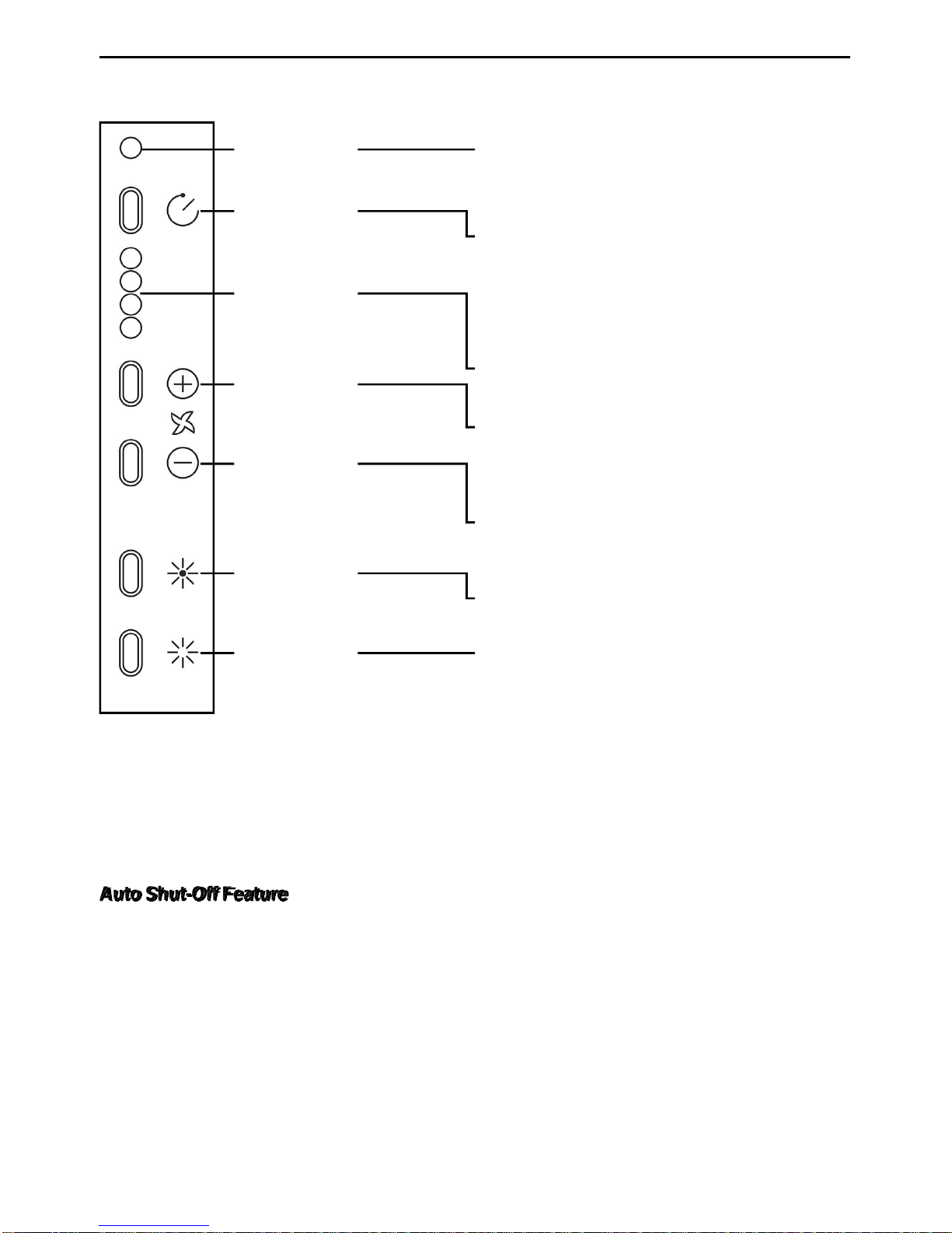
OPERATION
Controls (Fig.1)
The hood is operated using the (5) push buttons located on the front edge of the hood.
Filter Alarm
Indicator
Filter Alarm /
Timer Reset
Speed
Indicators
Blower
On / Speed
Blower
Off / Speed
Light On
When LED is red (motor off) it indicates the
filter alarm. When LED is green flashing, it
indicates timer is activated and Filter Alarm
/ Timer Reset button has been pressed.
When pressing the button during the display of the filter alarm (blower off) it resets
the filter alarm. When pressing the button
while the blower is on, it activates the tenminute timer function and the blower will
automatically turn off in ten minutes.
The green LEDs indicate blower speed.
Activates the blower (at the last speed
used) and increases the blower speed until
the maximum speed is achieved.
Decreases the blower speed. If pressed for
two seconds, the blower will turn off.
Turns lights on
Light Off
Filter Alarm
After 30 hours of blower operation, the filter alarm is activated and Filter Alarm Indicator
LED turns red. It indicates the grease filters need to be cleaned.
After 120 hours of blower operation, the filter alarm is activated and Filter Alarm Indicator
LED turns red and flashes. It indicates the grease filters need to be cleaned and the
charcoal filters need to be replaced (for non-ducted applications).
After cleaning the grease filters (and/or replacing the charcoal filters), reset the hour counter
by pressing the Filter Alarm / Timer Rest button during display of the alarm.
Auto Shut-Off Feature
If the blower and/or the lights are on continuously for 10 hours without any user interaction
with the controls, the hood will automatically shut off. Press any control button to re-activate
the hood.
HEAT SENTRY
Your hood is equipped with a HEAT SENTRY thermostat. This thermostat is a device that
will turn on or speed up the blower if it senses excessive heat above the cooking surface.
1) If blower is OFF - it turns blower ON to HIGH speed.
2) If blower is ON at a lower speed setting - it turns blower up to HIGH speed.
When the temperature level drops to normal, the blower will return to its original setting.
Turns lights off
WARNING
The HEAT SENTRY thermostat can start the blower even if the hood is turned OFF.
When this occurs, it is impossible to turn the blower OFF with its switch. If you must
stop the blower, do it from the main electrical panel.
- 6 -
Page 7

REMOTE CONTROL
The remote control is linked to the hood at the factory.
If, for some reason, the link is lost - follow the directions below:
To Link Remote Control to Hood
1. Turn off hood motor and hood lights.
2. Press on the remote control for at least 3 seconds and release the button. The indicator
light will light up (Fig. 2).
3. Within 3 seconds press P5 on the hood control (Fig. 3). The BEEP confim that the
linking process was successful.
HOOD CONTROL
INDICATOR
LIGHT
P5
P4
P3
P2
FIG. 2 FIG. 3
P1
Remote Control Functions (Fig.2)
Delay - Off
Blower Speed Decrease and Off
Blower Speed Increase and On
Light
See Controls section on previous page for more information on each function.
CAUTION RISK OF EXPLOSION IF BATTERY IS
REPLACED BY AN INCORRECT TYPE. DISPOSE
OF USED BATTERY TO THE INSTRUCTION.
Battery disposal
When the batteries need to be replaced, dispose of them only and exclusively in the numerous
readily available special waste bins, especially in shops selling electronic consumer goods.
Observance of the regulations on differentiated waste collection, in particular, proper disposal of
used batteries, contributes to preventing possible negative effects on the environment and health.
- 7 -
Page 8
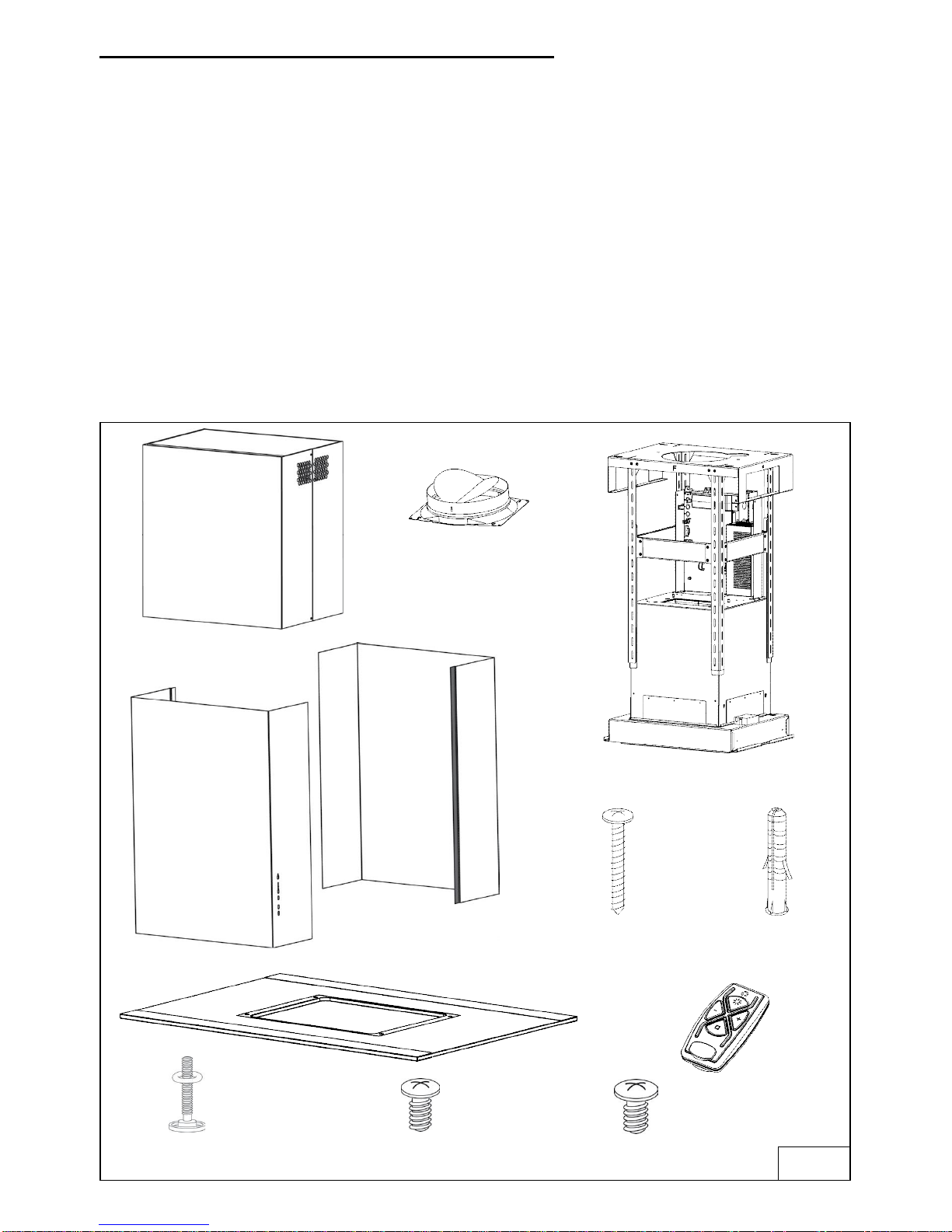
PREPARE THE HOOD
Unpack hood and check contents.
You should receive:
1 - Hood
1 - Upper Decorative Flues
2 - Lower Decorative Flues
1 - Support Frame
1 - Glass
1 - Duct Collar
1 - Parts Bag (B080811005) containing:
2 - Mounting Screws (M4 x 8mm Pan Head)
2 - Mounting Screws (3,9 x 6mm Flat Head)
4 - Aesthetic Screws (M4 x 16mm Flat Head)
6 - Mounting Screws (4,8 x 38mm Pan Head)
6 - Drywall Anchors
1 - Installation Instructions
1 - Remote Control
UPPER
DECORATIVE
FLUES
DUCT COLLAR
LOWER
DECORATIVE
FLUES
SUPPORT
FRAME
6 MOUNTING SCREWS
(4,8x38mm Pan Head)
6 DRYWALL
ANCHORS
GLASS
4 AESTHETIC SCREWS
(M4x16mm Flat Head)
2 MOUNTING SCREWS
(M4x8mm Pan Head)
- 8 -
2 MOUNTING SCREWS
(3,9x6mm Flat Head)
1 REMOTE
CONTROL
FIG. 4
Page 9
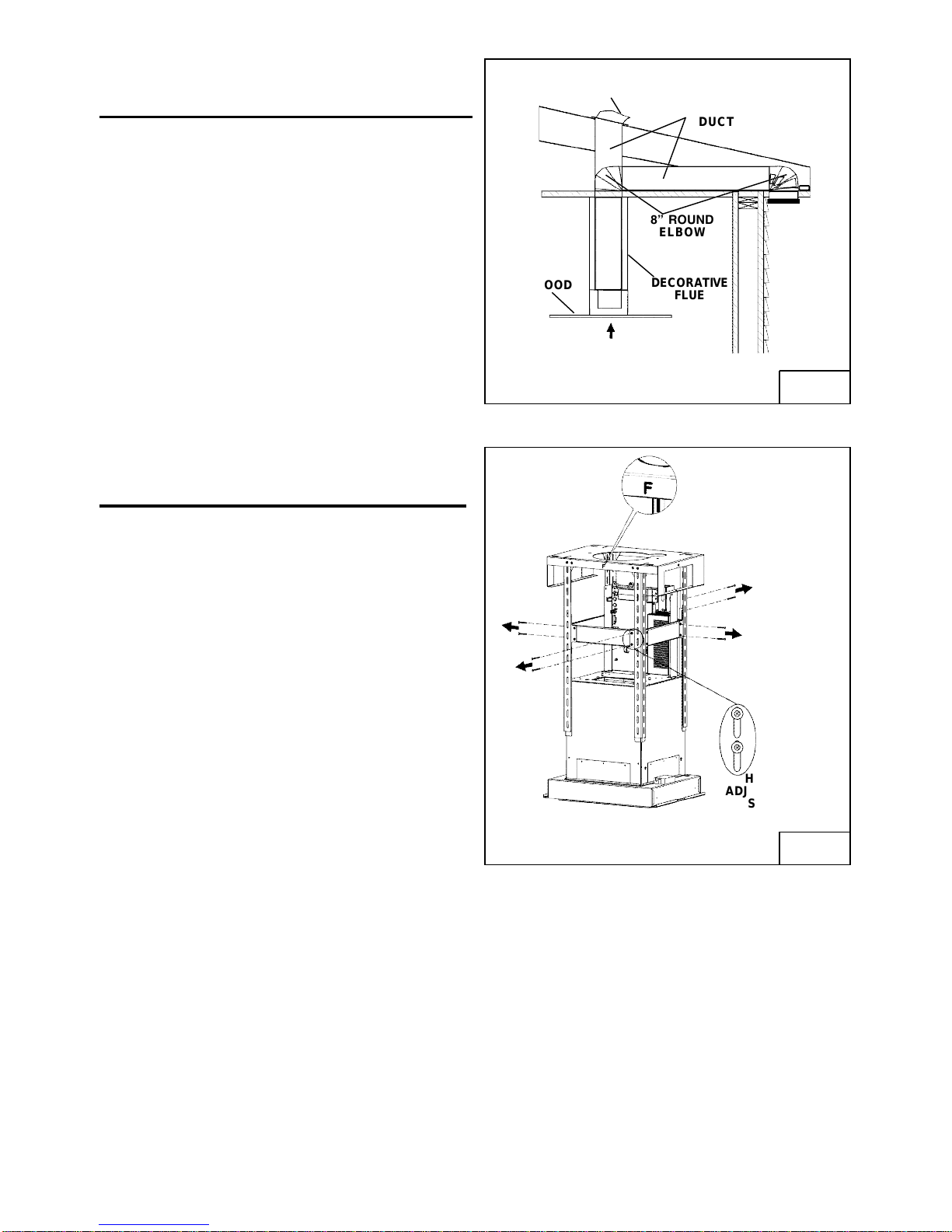
INSTALL THE DUCTWORK
IFC6IQ Series
WARNING: To reduce the risk of fire, use
only metal ductwork.
1. Decide where the ductwork will run
between the hood and the outside.
2. A straight, short duct run will allow the hood
to perform most efficiently.
3. Long duct runs, elbows, and transitions will
reduce the performance of the hood. Use
as few of them as possible.
4. Install a roof or wall cap. Connect 8" round
metal ductwork to cap and work back
towards hood location. Use duct tape to
seal the joints between ductwork sections.
INSTALL THE DUCTWORK
IFC6IQ Series
ROOF CAP
HOOD
24 TO 36 ABOVE
COOKING SURFACE
8 ROUND
DUCT
8 ROUND
ELBOW
DECORATIVE
FLUE
FIG. 5
1. Before making the holes on the ceiling,
unscrew the (8) screws (3.9x6mm) from the
upper support frame.
HEIGHT
ADJUSTMENT
SLOTS
FIG. 6
- 9 -
Page 10
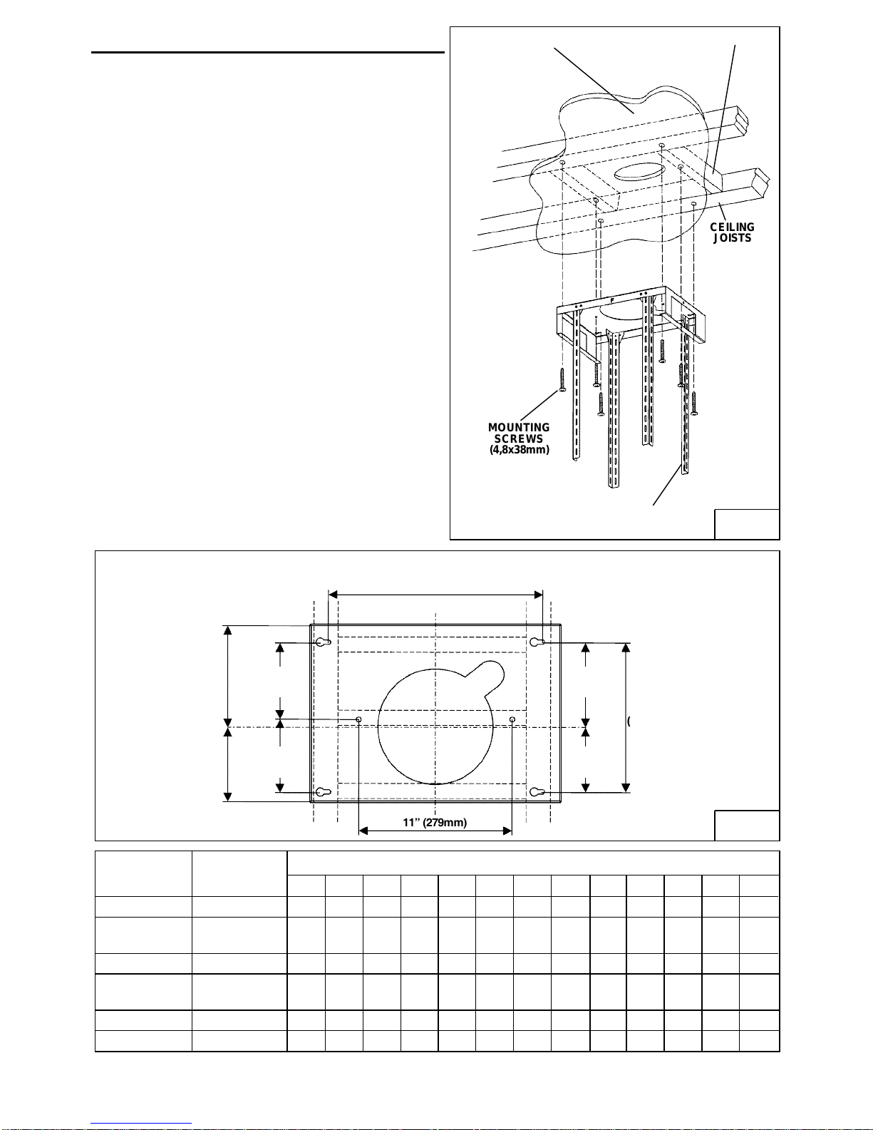
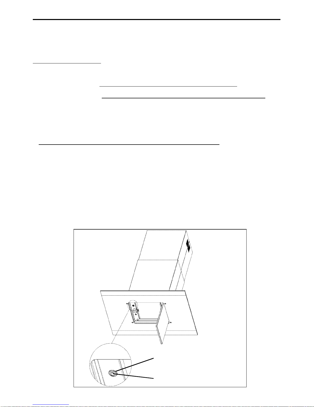
INSTALL SUPPORT SYSTEM
1. At hood location, install 2 x 4 or larger cross
framing between ceiling joists using
dimensions shown.
2. Finish the ceiling surface. Be sure to mark
the location of the ceiling joists and cross
framing.
3. Adjust the overall height using the chart
below of the support frame. Loosen and retighten the 4 screws in the height
adjustment slots as necessary. Insert 12
screws (3.9x6mm) (Fig.7). Make sure this a
4 min. overlap between the upper & lower
support legs.
4. Secure the support frame to joists and cross
framing with six (6) screws provided
(4,8x38mm). Make sure screws are driven
into center of joists and framing for maximum strength.
Notes:
a. - = Mounting height is not possible
b. Minimum hood distance above cook top
must not be less than 24. A maximum of
30 above cook top is highly
recommended for best capture of cooking
impurities. Distances over 36 are at the
installer and the users discretion; and if
ceiling height and flue lenght permit.
c. Requires optional 10 / 11 flue extension,
ducted model AEICFSB.
TOP VIEW OF SUPPORT FRAME
DRYWALL
MOUNTING
SCREWS
(4,8x38mm)
SUPPORT
FRAME
CROSS FRAMING
CEILING
JOISTS
FIG. 7
7 3/8
(187mm)
5 7/16
(138mm)
Ceiling
Height
Duct
Method
8 Feet Ducted
Non-
Ducted
9 Feet Ducted
Non-
Ducted
10 Feet (c) Ducted
11 Feet (c) Ducted
5 9/16
(141mm)
5 3/16
(131,5mm)
15 3/8 (390mm)
6 1/16
(154mm)
10 3/4
(273mm)
4 11/16
(119mm)
11 (279mm)
Hood Distance Above 36 High Cook Top (in.) (b)
24 25 26 28 29 30 31 32 33 34 35 3627
X
X X X X X - - - - - - -
- (a) - - - - - - - - - - - -
- - - X* X* X* X* X X X X X X
- - - X X X X X X X X X X
X X X X X X X X X X X X X
X X X X X X X - - - - - -
FIG. 8
* = Non duct opening exposed
- 10 -
Page 11
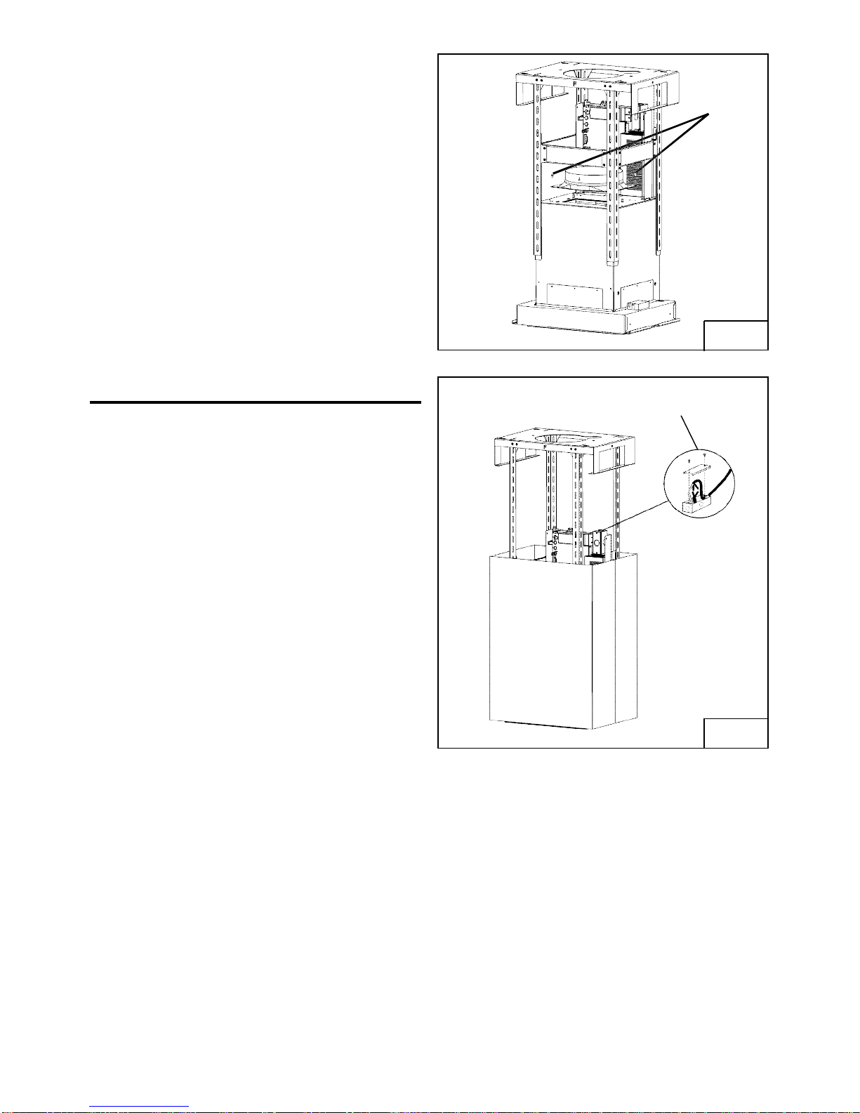
5. Fix the duct connector to the hood by using
2 screws (3.9x9.5mm) located in the
Hardware Package (Fig.9).
See page 14 for non-duct installation
MOUNTING
SCREWS
3,9x9,5mm
FIG.9
WIRING (ICF6)
Note: This range hood must be properly
grounded. The unit should be installed by a
qualified electrician in accordance with all
applicable national and local electrical
codes.
1. Remove the wiring box cover. Remove a
knockout from the wiring box (Fig.10).
2. Secure the wire to the wiring box through
an approved connector.
3. Make electrical connections. Connect white
to white, black to black and green to green.
4. Replace wiring box cover and screws.
Make sure that wires are not pinched
between cover and box.
WIRING BOX
COVER
FIG.10
- 11 -
Page 12

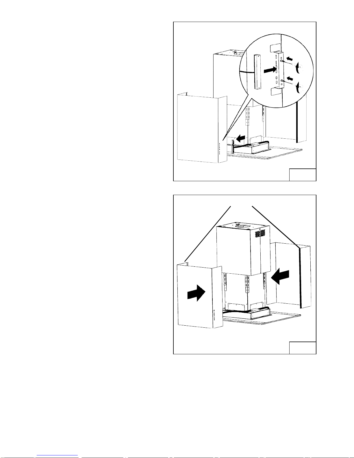
CONNECT DECORATIVE FLUE
DUCTED INSTALLATION ONLY
Note: Rooms with 10 or 11 foot ceilings
require flue extension model AEICF6SB,
available from your local dealer. Discard
the upper flue supplied with the range
hood and replace it with the longer flue
extension.
1. Insert the upper flue in the support frame
(Fig.11).
2. Secure the hood to the ceiling.
FIG. 11
3. Attached the upper flue to the upper
support frame by mounting screws
M4x8mm (Fig.12).
4. Fix the glass to the support frame by 4
aesthetic screws M4x16 plus the o-ring
located in the Hardware Package.
IMPORTANT: insert the aesthetic
screws as shown in Fig.13.
MOUNTING SCREWS M4x8mm
FIG. 12
MOUNTING SCREWS M4x16mm + O RING
- 12 -
FIG. 13
Page 13
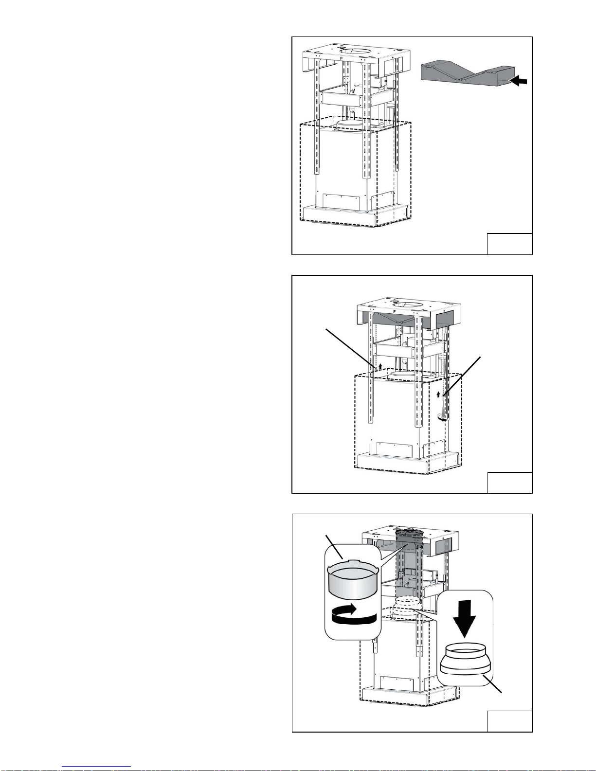
5. Install the switch box assembly in to the
front lower flue by tightening the 2
screws already inserted in the bracket
welded to the flue (Fig.14).
FIG. 14
6. Attach the two lower flue parts to the
support frame by overlapping the lateral
magnets (Fig.15).
MAGNET
FIG. 15
- 13 -
Page 14
NON-DUCTED INSTALLATION ONLY
Note: Rooms with 10 or 11 foot ceilings
require flue extension model
AEICF6SB, available from your local
dealer. Discard the upper flue supplied
with the range hood and replace it with
the longer flue extension.
1. Insert the plenum in to the upper support
frame (Fig.16).
2. Attach the plenum to the upper support
frame using (2) 3.9 x 6mm flat head
screws provided, as shown in Fig.17.
FIG. 16
MOUNTING
SCREWS
(3,9x6mm)
MOUNTING
SCREWS
(3,9x6mm)
3. Attach the 6-to-8 adapter to the blower
outlet and attach 6ducting connector to
the plenum (Fig.18).
4. Attach expandable duct to the plenum
through the duct connector (Fig.18).
5. Attach the upper flue to the upper support
frame by the mounting screws M4x8mm
(Fig.12).
See page 12 and 13 for flue installation
instruction.
FIG. 17
DUCT
CONNECTOR
ADAPTER
FIG. 18
- 14 -
Page 15

INSTALL FILTERS
DUCTED AND NON-DUCTED HOODS
1.To remove the GREASE filter, open the
perimeter panel (Fig.19).
2. Move the two retaining clips as showed in
Fig.20
3.Pull down the handle (Fig.21) to disengage
the grease filter. Pull down the wave filter
using the lateral handles (Fig.22) and see
page 5 for cleaning instructions.
NON-DUCTED HOODS
1. Non-ducted recirculation filters not
included. They must be purchased
separately (AFCICF6 Kit).
2. Remove the wave filter (Fig.22) using the
lateral handlings and engage the charcoal
filter as shown in Fig.23.
3. The charcoal filter replacement model is
AFCWC345.
Non-ducted recirculation filters
The non-ducted recirculation filters should
be changed every 6 months.
FIG. 19
FIG. 21
FIG. 20
FIG. 23FIG. 22
- 15 -
Page 16
CALIBRATE IQ BLOWER SYSTEM
TM
INTERNAL BLOWER DUCTED UNITS ONLY
After the hood is installed and wired, engage the calibration process (our Guaranteed Performance
System Technology to ensure full-rated airflow is being delivered). Prior to calibration, ensure that all
filters, light bulbs and duct system are installed.
CALIBRATION PROCESS
Hold the calibration button for 3 seconds; calibration button will light up and stay on for up to 13 minutes.
The blower will start and begin the calibration process. When calibration is complete, one of two things
will occur:
1. The blower turns off and calibration button light stays on = Successful calibration. Press the button
to turn off the LED. Note: The LED will also turn off if you select any blower speed on the control.
2. The blower turns off and calibration button light blinks continuously = Too much restriction in the
ductwork is preventing the IQ Blower System from achieving the rated airflow. The blower is
automatically set to maximum intensity.
NOTE: Common items that cause restrictions: restricted damper flap (backdraft damper, wall cap,
roof cap), too many elbows, duct size less than 80% of hood outlet, poor transition, use of flex ducting
and/or crushed ducting.
Three options are available if your hood system has too much restriction:
1. Accept airflow as is.
a. Press the calibration button to accept airflow as is. The IQ Blower System is nowconfigured to
the highest possible performance. The blinking calibration light goes out. Note: The LED will also
turn off if you select any blower speed on the control.
2. Correct duct restriction, clear the original calibration data, and repeat the calibration process.
a. Correct the duct restriction.
b. Clear the original calibration data by holding calibration button for 10 seconds. The light will blink
3 times to confirm and the blower configuration will go back to default settings.
c. Repeat calibration process from the beginning.
3. Clear calibration data to reset hood to default factory setting and achieve standard high
pressure blower performance.
a. Clear calibration data and reset hood to factory default setting by holding calibration
button for 10 seconds. The light will blink 3 times to confirm and the blower configuration
will go back to default settings.
CALIBRATION
BUTTON
CALIBRATION LIGHT
- 16 -
Page 17
WARRANTY
Broan-NuTone LLC (Broan-NuTone) warrants to the original consumer purchaser of Best products that such products will be free
from defects in materials or workmanship for a period of one year from the date of original purchase. THERE ARE NO OTHER
WARRANTIES, EXPRESS OR IMPLIED, INCLUDING, BUT NOT LIMITED TO, IMPLIED WARRANTIES OR MERCHANT ABILITY
OR FITNESS FOR A PARTICULAR PURPOSE.
During this one-year period, Broan-NuTone will, at its option, repair or replace, without charge, any product or part which is found
to be defective under normal use and service.
THIS WARRANTY DOES NOT EXTEND TO FLUORESCENT LAMP STARTERS, TUBES, HALOGEN AND INCANDESCENT
BULBS, FUSE, FILTERS, DUCTS, ROOF CAPS, WALL CAPS AND OTHER ACCESSORIES FOR DUCTING. This warranty does
not cover (a) normal maintenance and service or (b) any products or parts which have been subject to misuse, negligence,
accident, improper maintenance or repair (other than by Broan-NuTone), faulty installation or installation contrary to recommended installation instructions.
The duration of any implied warranty is limited to the one-year period as specified for the express warranty. Some states do not
allow limitation on how long an implied warranty lasts, so the above limitation may not apply to you.
BROAN-NUTONE'S OBLIGATION TO REPAIR OR REPLACE, AT BROAN-NUTONE'S OPTION, SHALL BE THE PURCHASER'S
SOLE AND EXCLUSIVE REMEDY UNDER THIS WARRANTY. BROAN-NUTONE SHALL NOT BE LIABLE FOR INCIDENTAL,
CONSEQUENTIAL OR SPECIAL DAMAGES ARISING OUT OF OR IN CONNECTION WITH PRODUCT USE OR PERFORMANCE.
Some states do not allow the exclusion or limitation of incidental or consequential damages, so the above limitation or exclusion
may not apply to you.
This warranty gives you specific legal rights, and you may also have other rights, which vary from state to state. This warranty
supersedes all prior warranties.
To qualify for warranty service, you must (a) notify Broan-NuTone at the address stated below or telephone number stated below,
(b) give the model number and part identification and (c) describe the nature of any defect in the product or part. At the time of
requesting warranty service, you must present evidence of the original purchase date.
In USA - Best®, 926 W. State Street, Hartford, WI 53027 (800-558-1711)
In Canada - Best®, 550 Lemire Blvd., Drummondville, QC J2C 7W9 (866-737-7770)
www.BestRangeHoods.com
ONE YEAR LIMITED WARRANTY FOR BEST PRODUCTS
- 17 -
Page 18
SERVICE PARTS
MODEL ICF6IQ100SB
KEY NO. PART NO. DESCRIPTION
9 B08087675 Grease Filters
37 B02300804 Heat Sentry
67 B06102620 Wires Assembly
76 B08092902 Glass
114 B032904990 Wire Clamp
115 BE3350233 Wiring Box
116 BE3334252 Wiring Box Cover
118 B08092906 Lower Flue
119 B08092909 Upper Flue
124 B08092904 Telescopic Structure Bottom
125 BE3405258 Telescopic Structure Top
202 B03292290 Wire Clamp
250 B02011389 Ring Nut
274 B03295035 Fuse Box
312 B03115336 Inside Panel
343 B08092900 Panel
362 B02011377 Magnet
415 B03292169 Fairlead
439 B02320034 Grommet
474 B02300885 Led Lamp
477 B02011354 Closing
506 97019431 BLDC Driver
507 B06102584 Calibration Button Assembly
AQI B06102594 Switch Box Assembly
ARU B080810849 Duct Connector Assembly 8
IME B06145222 Electrical Installation Assembly
CAS B06002259 Blower Assembly
* B080811005 Fitting Set
ACR3 B08999186 Remote Control
ANKICF6 B08999180 Non-Ducted Kit (Includes Key No. 58, 86, 122, 503)
58 B03294170 Outlet Reduction
86 B03292300 Outlet Flange
122 B08093495 Non-Duct Plenum
503 B02011557 Expandable Duct
AFCICF6 B08999179 Non-Duct Filter
* Not shown assembled.
- 18 -
Page 19

- 19 -
Page 20

- 20 -
Page 21

Modèle ICF6
IAux États-Unis - BEST Hartford, Wisconsin
Au CANADA - BEST Drummondville, QC, Canada
ENREGISTREZ VOTRE PRODUIT EN LIGNE À : www.BestRangeHoods.com/register
Pour de plus amples informations, visitez www.BestRangeHoods.com
ENGLISH........................................3
FRANÇAIS...................................21
ESPAÑOL.....................................41
- 21 -
Page 22

- 22 -
Page 23

LIRE CES DIRECTIVES ET LES CONSERVER
!
CONÇUE POUR LES CUISINES PRIVÉES UNIQUEMENT
!
AVERTISSEMENTS
POUR RÉDUIRE LES RISQUES DINCENDIE, DÉLECTROCUTION OU DE BLESSURES
PHYSIQUES, RESPECTEZ LES INSTRUCTIONS CI-DESSOU:
1. Utilisez cet appareil uniquement de la manière prévue par le fabricant. Si vous avez des ques-
tions, contactez le fabricant à ladresse ou au numéro de téléphone indiqués dans la garantie.
2. Avant deffectuer lentretien ou le nettoyage de lappareil, mettez-le hors tension sur le panneau
de service et verrouillez ce dernier pour éviter que lappareil soit mis sous tension par
inadvertance. Sil nest pas possible de verrouiller le dispositif de déconnexion, apposez un
avertissement bien visible (par exemple une étiquette) sur le panneau de service.
3. Linstallation et le raccordement électrique doivent être effectués par du personnel qualifié con-
formément à toutes les réglementations et normes en vigueur, y compris celles concernant les
constructions cotées pour leur résistance au feu.
4. Afin déviter un refoulement lors de lutilisation déquipements à combustible, une quantité dair
suffisante est nécessaire pour assurer une combustion et un échappement adéquats des gaz à
travers le conduit (la cheminée). Suivez les consignes du fabricant de léquipement chauffant et
les normes de sécurité publiées, entre autres, par lAssociation nationale de protection contre
lincendie (NFPA) et lAmerican Society for Heating, Refrigeration and Air Conditioning Engineers
(ASHRAE), ainsi que les réglementations locales.
5. Quand vous effectuez une découpe ou un forage dans un mur ou un plafond, veillez à ne pas
endommager des câblages électriques ou dautres équipements non visibles.
6. Les soufflantes canalisées doivent toujours être dirigées vers lextérieur.
7. Nutilisez pas cet appareil avec un dispositif de commande de vitesse transistorisée séparé.
8. Pour réduire les risques dincendie, utilisez uniquement des canalisations en métal.
INSTRUCTIONS DE MISE À LA TERRE
Cet appareil doit être mis à la terre. En cas de court-circuit électrique, la mise à la terre réduit le
risque délectrocution grâce à un fil permettant au courant électrique de séchapper.
AVERTISSEMENT - Une mise à la terre inappropriée peut donner lieu à un risque délectrocution.
Consultez un électricien qualifié si vous ne comprenez pas parfaitement les instructions de mise à
la terre ou si vous nêtes pas certain(e) que lappareil est mis à la terre comme il se doit.
POUR RÉDUIRE LE RISQUE DUN FEU DE FRITURE SUR LA TABLE DE CUISSON
A. Ne laissez jamais les appareils de surface sans surveillance quand ils sont sur un réglage élevé.
Les débordements peuvent provoquer de la fumée et des déversements gras risquant de
prendre feu. Chauffez les huiles lentement sur un réglage bas ou moyen.
B. ALLUMEZ toujours la hotte quand vous cuisinez à une chaleur élevée ou quand vous flambez
des aliments (p. ex. des crêpes Suzette, des cerises jubilé ou du boeuf au poivre flambé).
C. Nettoyez souvent les ventilateurs daération. Évitez que de la graisse saccumule sur le
ventilateur ou le filtre.
D. Utilisez des poêles de la taille appropriée. Utilisez toujours des ustensiles de cuisine adaptés à la
taille de lélément de surface.
- 23 -
Page 24

AVERTISSEMENTS
POUR RÉDUIRE LE RISQUE DE BLESSURES PHYSIQUES EN CAS DE FEU DE FRITURE
SUR LA TABLE DE CUISSON, VEUILLEZ PROCÉDER COMME SUIT :*
1. ÉTOUFFEZ LES FLAMMES avec un couvercle hermétique, une plaque à biscuits ou un
plateau en métal, puis éteignez le brûleur. SOYEZ PRUDENT(E) AFIN DÉVITER LES
BRÛLURES. Si les flammes ne séteignent pas immédiatement, ÉVACUEZ LE LIEU ET
APPELEZ LE SERVICE DES POMPIERS. 2. NE SAISISSEZ JAMAIS UNE POÊLE
ENFLAMMÉE, vous risquez de vous brûler.
3. NUTILISEZ JAMAIS DEAU ni de torchons ou serviettes mouillé(e)s : cela donnerait lieu à une
violente explosion de vapeur.
4. Utilisez un extincteur UNIQUEMENT si :
A. Vous savez quil sagit dun extincteur de Classe ABC et savez déjà comment vous en servir.
B. Lincendie est de petite taille et confiné à lendroit où il a commencé.
C. Le service des pompiers a été averti.
D. Vous pouvez éteindre lincendie en ayant une sortie derrière vous.
* Basé sur « Kitchen Fire Safety Tips », publié par la NFPA.
!
ATTENTION
1. Uniquement pour lutilisation intérieure.
2. Pour réduire le risque dincendie et obtenir un échappement dair adéquat, veillez à bien canaliser lair vers lextérieur. Ne ventilez pas lair déchappement vers des espaces confinés,
des plafonds, des combles, des vides sanitaires ou des garages.
3. Soyez prudent(e) quand vous utilisez des agents de nettoyage ou des détergents.
4. Évitez dutiliser sous la hotte de cuisine des denrées alimentaires produisant des flammes.
5. À utiliser uniquement pour la ventilation générale. Nutilisez pas la hotte pour léchappement de
matériaux ou de vapeurs comportant un danger ou un risque dexplosion.
6. Pour éviter que le roulement moteur sendommage et que des hélices deviennent bruyantes ou
déséquilibrées, faites en sorte que le bloc dalimentation nentre pas en contact avec un
atomiseur pour cloisons sèches, de la poussière de construction, etc.
7. Le moteur de la hotte est doté dun rupteur thermique qui éteint automatiquement le moteur en
cas de surchauffe. Le moteur redémarrera après avoir refroidi. Si le moteur séteint et se
rallume constamment, faites réparer la hotte.
8. Pour mieux capturer les impuretés de cuisson, la partie inférieure de la hotte doit se trouver au
minimum à 61 cm (24) et au maximum à 91,4 cm (36) au-dessus de la surface de cuisson.
Consultez la section « Installation du support de montage » pour connaître les restrictions de
montage.
9. Étant donné la taille et le poids de la hotte, il est conseillé davoir recours à deux personnes
pour la monter.
10. Ce produit est doté dun thermostat qui peut activer la soufflante automatiquement. Pour éviter
les risques de blessure et lallumage accidentel de la hotte, mettez-la hors tension sur le
panneau de service et verrouillez ce dernier ou fixez-y une étiquette davertissement.
11. Pour en savoir plus et connaître les exigences sur le produit, veuillez lire létiquette des
spécifications.
12. Le panneau de verre sur ce capot ne doit pas être utilisé comme étagère.
- 24 -
Page 25

LAMPES À LED
Cette hotte comprend des lampes LED qui nexigent aucun entretien.
NETTOYAGE ET ENTRETIEN
Pour assurer les performances de l'appareil, entretenez-le de manière appropriée.
Moteur
Le moteur est lubrifié en permanence et aucun graissage n'est nécessaire. Si les
roulements du moteur font un bruit excessif ou inhabituel, remplacez le moteur par une
pièce de rechange identique.
Remplacez aussi les hélices.
Filtre à graisse
Le filtre à graisse doit être nettoyé souvent. Vous pouvez utiliser une solution détergente
chaude ou le mettre dans le lave-vaisselle.
Nettoyez tous les filtres en métal dans le lave-vaisselle avec un détergent sans phosphate.
Si vous utilisez un détergent phosphaté ou selon le type d'eau, il est possible que le filtre se
décolore, mais cela n'affectera aucunement ses performances. Cette décoloration n'est pas
couverte par la garantie. Consultez la section « INSTALLATION DES FILTRES » pour
connaître les instructions de retrait et d'installation.
Filtre de recirculation non canalisé
Le filtre de recirculation non canalisé doit être changé tous les 6 mois. Si votre style de
cuisine engendre beaucoup de graisse, par exemple si vous faites souvent de la friture ou
utilisez un wok, remplacez-le plus souvent. Consultez la section « INSTALLATION DES
FILTRES » pour connaître les instructions de retrait et d'installation.
Nettoyage de l'acier inoxydable
À FAIRE :
nettoyez régulièrement l'acier inoxydable
avec un chiffon ou un torchon enduit d'eau
chaude et de savon doux ou de liquide
vaisselle.
nettoyez toujours dans le sens des lignes
de polissage d'origine.
rincez toujours à l'eau claire (2 ou 3 fois)
après le nettoyage. Essuyez
complètement.
vous pouvez aussi utiliser un nettoyant
spécial pour acier inoxydable
d'électroménagers.
À éviter quand vous choisissez un détergent :
tous les produits de nettoyage contenant de l'eau de Javel attaquent l'acier inoxydable.
tous les produits contenant du chlore, du fluor, de l'iode ou du bromure provoquent une
détérioration rapide des surfaces.
tous les produits combustibles utilisés pour le nettoyage, tels que l'acétone, l'alcool,
l'éther, le benzène sont extrêmement explosifs et ne doivent jamais être employés à
proximité d'une table de cuisson.
À NE PAS FAIRE :
n'utilisez pas de laine d'acier inoxydable
ou d'autres racloirs pour éliminer la saleté
difficile à éliminer.
n'utilisez pas de produits de nettoyage
durs ou abrasifs.
ne laissez pas la poussière s'accumuler.
maintenez la hotte à l'abri de la
poussière de plâtre ou d'autres résidus de
construction. Pen-dant la construction/les
rénovations, couvrez la hotte afin d'éviter
qu'aucune poussière n'adhère aux
surfaces en acier inoxydable.
- 25 -
Page 26

FONCTIONNEMENT
Commandes (Fig.1)
La hotte sutilise à laide des 5 boutons-poussoirs situés sur le devant de la hotte.
Alarme du filtre
Voyant
Alarme du filtre/
Réinitialisation
de la minuterie
Vitesse
Voyant
Soufflante
Démarrage/
vitesse
Soufflante
Extinction/
vitesse
Lumière
allumée
Lorsque la DEL est rouge (moteur coupé), cela indique
une alarme du filtre. Lorsque la DEL clignote, cela indique que la minuterie est activée et que le bouton de filtre
dalarme/réinitialisation de la minuterie a été enfoncé.
En enfonçant le bouton durant laffichage de lalarme
du filtre (soufflante arrêtée), cela réinitialise lalarme du
filtre. En enfonçant le bouton tandis que la soufflante
est en marche, il active la fonction retardateur de dix
minutes et la soufflante séteindra automatiquement
après dix minutes.
Les DEL vertes indiquent la vitesse de la soufflante.
Active la soufflante (à la dernière vitesse utilisée) et
augmente la vitesse de soufflante jusquà ce que la
vitesse maximum soit atteinte.
Réduit la vitesse de la soufflante. Si enfoncé pendant
deux secondes, la soufflante séteindra.
Allume les lumières
Lumière
éteinte
Alarme du filtre
Après 30 heures de fonctionnement de la soufflante, lalarme du filtre sactive et la DEL du
voyant dalarme du filtre devient rouge. Cela indique que les filtres à graisse doivent être
nettoyés. Après 120 heures de fonctionnement de la soufflante, lalarme du filtre sactive et
la DEL du voyant dalarme du filtre devient rouge et clignote. Cela indique que les filtres à
graisse doivent être nettoyés et les filtres à charbon doivent être remplacés (pour les
applications sans canalisation). Après avoir nettoyé les filtres à graisse (et/ou remplacé les
filtres à charbon), réinitialisez le compteur en enfonçant le bouton dalarme du filtre/
réinitialisation de minuterie durant laffichage de lalarme.
Fonction darrêt automatique
Si le ventilateur ou léclairage reste continuellement allumé pendant 10 heures sans que
lutilisateur interagisse avec les commandes, la hotte sarrêtera automatiquement. Appuyez
sur tout de bouton de commande pour remettre la hotte en marche.
HEAT SENTRY
La hotte est équipée d'un thermostat HEAT SENTRY. Ce dispositif active ou accélère la
soufflante s'il détecte une chaleur excessive au-dessus de la surface de cuisson.1) Si la
soufflante est ARRÊTÉE, il l'ALLUME sur la vitesse HAUTE.2) Si la soufflante est ALLUMÉE
à une vitesse basse, il la fait passer à la vitesse HAUTE.Quand la température redevient
normale, la soufflante retourne au réglage d'origine.
Éteint les lumières
AVERTISSEMENT
Le thermostat HEAT SENTRY peut activer la soufflante même si la hotte est éteinte.
Dans ce cas, il est impossible de désactiver la soufflante avec le commutateur d'ARRÊT.
Si vous devez ARRÊTER la soufflante, faites-le depuis le panneau électrique principal.
- 26 -
Page 27

TÉLÉCOMMANDE
La télécommande est jumelée à la hotte dès sa sortie de lusine.
Si pour une raison quelconque cette liaison est perdue veuillez suivre les directives ci-
dessous :
Liaison de la télécommande à la hotte
1. Arrêtez le moteur de la hotte et éteignez léclairage.
2. Appuyez sur le bouton de la télécommande pendant au moins 3 secondes, puis
relâchez le button. Le témoin lumineux sallume (Fig.2).
3. Dans les 3 secondes, appuyez sur P5 sur le panneau de commande de la hotte (Fig.3). Le BIP
confim que le processus de liaison a réussi.
PANNEAU DE COMMANDE DE LA HOTTE
TÉMION
LUMINEUX
P5
P4
P3
P2
FIG. 2 FIG. 3
P1
Fonctions de la télécommande (Fig.2)
Arrêt différé - Désactivé
Bouton de réduction de la vitesse du ventilateur et darrêt
Bouton de mise en marche et daugmentation de la vitesse du ventilateur
Éclairage
Pour de plus amples information sur chaque fonction, consultez la section Commandes
à la page précédente.
ATTENTION IL Y A RISQUE DEXPLOSION SI LA
PILE EST REMPLACÉE PAR LE MAUVAIS TYPE.
METTRE LES PILES USÉES AU REBUT
CONFORMÉMENT AUX INSTRUCTIONS.
Miseau rebut des piles
Lorsque les piles doivent être remplacées, prenez soin de les déposer dans lun des nombreux bacs de
recyclage répartis au pays, particulièrement dans les magasins délectronique. Le respect des normes en
matière de collecte sélective, particulièrement pour la mise au rebut des piles usées, contribue à éviter de
possibles effets négatifs sur lenvironnement et la santé.
- 27 -
Page 28

PRÉPARATION DE LA HOTTE
Déballez la hotte et vérifiez le contenu de lemballage.
Il doit comprendre :
1 - Hotte
1 - De carneau décoratif supérieur
2 - De carneau décoratif inférieur
1 - Structure de support
1 - Verre
1 - Collier dévacuation
1 - Sac de pièces (B080811005) contenant:
2 - Vis de montage (à tête cylindrique M4x8mm)
2 - Vis de montage (à tête plate 3,9x6mm)
4 - Vis esthétique (à tête plate M4x16mm)
6 - Vis de montage (à tête cylindrique 4,8 x 38 mm)
6 - Ancrages pour cloison sèche
1 - Instructions dinstallation
1 - Télécommande
CARNEAU
DÉCORATIF
SUPERIEUR
COLLIER
DEVACUATION
CARNEAU
DÉCORATIF
INFERIEUR
STRUCTURE
DE SUPPORT
6 VIS DE MONTAGE
(à tête cylindrique de
4,8 x 38 mm)
6 ANCRAGES
POUR CLOISON
SÈCHE
VERRE
4 VIS ESTHÉTIQUE
(à tête plate M4x16mm)
2 VIS DE MONTAGE
(à tête cylindrique M4x8mm)
- 28 -
1 TÉLÉCOMMANDE
2 VIS DE MONTAGE
(à tête plate 3,9x6mm)
FIG. 4
Page 29

INSTALLER LES CONDUITS
IFC6IQ
REMARQUE: pour réduire les risques
dincendie, utilisez uniquement des
conduits métalliques.
1. Décidez où le tuyau doit être installé, entre
votre hotte et lextérieur.
2. Un conduit droit et court permettra à votre
hotte de fonctionner dune façon plus efficace.
3. Un conduits long avec des coudes et des
transitions réduira le bon fonctionnement de
votre hotte. En utiliser le moins possible.
4. Installez un couvercle sur le toit ou au mur.
Reliez un tuyau en métal rond de 8 au
couvercle et faites-le aller jusquà
lemplacement de votre hotte. Utiliser du
ruban adhésif pour sceller les joints entre
les sections de conduits.
INSTALLER LES CONDUITS
IFC61IQ SÉRIE
COUVERCLE DU
TOIT
COUDE ROND
HOOD
24 (61cm) À 36 (91,4 cm)
AU-DESSUS DU PLAN DE
CUISSON
CARNEAU
DÉCORATIF
TUYAU ROND
DE 8
DE 8
FIG. 5
1. Avant de faire les truos au plafond,
dévisser les (8) vis (3.9x6mm) de la base
de support supérieur.
FISSURE POUR
RÉGLAGE EN
HAUTEUR
FIG. 6
- 29 -
Page 30

INSTALLATION DU SYSTEME DE
SUPPORT
1. Installez, à lemplacement de votre hotte, un cadre croisé
de 2 x 4 entre les solives du plafond en suivant les
dimensions qui vous sont indiquées.
2. Perfectionnez la surface du plafond. Assurez-vous de bien
marquer lempla-cement des solives et du cadre croisé au
plafond.
3. Réglez la hauteur totale de la structure de support en utilisant
le tableau ci-dessus. Désserrez et resserrez les 4 vis dans
les fissures permettant de régler la hauteur selon ce qui
est nécessaire. Installez 12 vis (3.9x6mm) qui se trouvent à
lintérieur du sachet accessoires. (Fig.7). Assurez-vous que
cet un min.4 chevauchement entre la partie supérieure et
les jambes de la structure de support inférieurs.
4. Fixez la structure de support aux solives et au cadre croisé
au moyen des six (6) vis (4,8x38mm). Assurez-vous que
les vis soient bien centrées dans les solives et dans le
cadre croisé de sorte que le tout soit bien solide.
Remarques:
a. - = Hauter de montage nest pas possible.
b. La distance minimale de la hotte au-dessus de la table
de cuisson ne doit pas être inférieure à 24. Un
maximum de 36 au-dessus de la table de cuisson est
fortement recommandé pour une meilleure évacuation
des odeurs de cuisson. Distances de plus de 30 sont les
installer et choix de lutilisateur, et si la hauteur de
plafond et le permis de longueur de combustion.
c. Requiert en option le carneaux extensible à 10 PI / 11 PI,
modèle canalisé AEICFSB.
VUE DE HAUT DU CADRE CROISÉ
CLOISON SÈCHE
VIS
DASSEMBLAGE
(4,8x38mm)
CADRE CROISÉ
STRUCTURE
DE SUPPORT
SOLIVES DU
PLAFOND
FIG. 7
(187mm)
(138mm)
Hauter de
Plafond
2,4 M (8 PI)
2,75 M (9 PI)
3,05 M (10 PI) (c)
7 3/8
5 7/16
Méthode de
Canalisation
Canalisèe X
NonCanalisèe
Canalisèe
NonCanalisèe
Canalisèe
Canalisèe3,35 M (11 PI) (c)
5 9/16
(141mm)
5 3/16
(131,5mm)
15 3/8 (390mm)
6 1/16
(154mm)
10 3/4
(273mm)
4 11/16
(119mm)
11 (279mm)
Distance de la Hotte à 90 cm (36) au-dessus de la Table de Cuisson (in.) (b)
24 25 26 28 29 30 31 32 33 34 35 3627
X X X X X - - - - - - -
- (a) - - - - - - - - - - - -
- - - X* X* X* X* X X X X X X
- - - X X X X X X X X X X
X X X X X X X X X X X X X
X X X X X X X - - - - - -
FIG. 8
* = Overture non sur conduit exposé
- 30 -
Page 31

5. Fixer le Collier dévacuation au haut de
votre hotte, la fixation a lieu au moyen
des 2 vis (3.9x9.5mm) qui se trouvent à
lintérieur du sachet accessoires (Fig.9).
Voir page 34 pour linstallation non-conduit.
VIS
DASSEMBLAGE
3,9x9,5mm
FIG.9
INSTALLATION ELECTRIQUE
(ICF6IQ)
Remarque: Ce modèle de hotte doit être
relié à la terre correctement. Cet article
devrait être installé par un électricien
qualifié selon les lois nationales et locales
en matière délectricité.
1. Enlevez le couvercle de la boîte de
connexion électrique. Ouvrez un trou de
la boîte de connexion électrique (Fig.10).
2. Fixer le conduit au boîtier de connexion
à laide dun connecteur approprié pour
ce conduit.
3. Faites le raccordement électrique. Reliez
le blanc au blanc, le noir au noir et le vert
au vert.
4. Remettez le couvercle de la boîte de
connexion et les vis. Assurez-vous que
les fils se sont pas coincés entre le
couvercle et la boîte.
COUVERCLE DE
LA BOÎTE DE
CONNEXION
FIG.10
- 31 -
Page 32

INSTALLATION DU CONDUIT
DECORATIF
INSTALLATION DUNE HOTTE CANALISÉE
Remarque: Les chambres avec plafond
de10 ou 11 pieds, exigent le carneau
dextension, modèle AEICF6SB, disponible
auprès devotre revendeur local. Jeter le
carneausupérieure fournie avec la hotte et
leremplacer avec lextension de carneau.
1. Introduire le conduit supérieur et inférieur
à la structure de support (Fig.11).
2. Fixez la hotte au plafond.
3. Attaché le conduit supérieur pour le
châssis de support supérieur avec les vis
de montage de M4x8mm (Fig.12).
4. Fixer le verre sur le cadre de support par
4 vis M4x16 esthétiques ainsi que le joint
torique situé dans le package de matériel.
IMPORTANT: insérez les vis esthétiques
comme le montre la figure 13.
FIG. 11
VIS DASSEMBLAGE M4x8mm
FIG. 12
VIS DASSEMBLAGE M4x16mm + O RING
- 32 -
FIG. 13
Page 33

5. Installez lassemblage de la boîte de
commutation pour la cheminée avant
inférieur en serrant les 2 vis déjà
insérées dans le support soudé à la
cheminée (Fig.14).
FIG. 14
6. Ci-joint les deux parties de coduit
inférieures à la structure de support en
faisant se chevaucher les magnet latéraux
(Fig.15).
MAGNET
FIG. 15
- 33 -
Page 34

INSTALLATION HOTTE NON CANALISÉE
Remarque: Les chambres avec plafond
de10 ou 11 pieds, exigent le carneau
dextension, modèle AEICF6SB,
disponible auprès devotre revendeur local.
Jeter le carneausupérieure fournie avec la
hotte et leremplacer avec lextension de
carneau.
1. Insérer le collecteur dans le structure de
support supérieur (Fig.16).
2. Fixer le collecteur à la structure de
support supérieure à l'aide des (2) 3,9 x
6mm vis à tête plate fournies, comme le
montre la Fig.17.
VIS
DASSEMBLAGE
(3,9x6mm)
FIG. 16
VIS
DASSEMBLAGE
(3,9x6mm)
3. Branchez ladaptateur 6 à 8 à la sortie
de la soufflerie et fixez connecteur 6
conduits à la chambre (Fig.18).
4. Fixez conduit extensible au plénum par
le connecteur de conduit (Fig.18).
5. Attacher le tuyau supérieur pour le
châssis de support supérieur par des vis
de montage M4x8mm (Fig.12).
Voir page 32 et 33 pour les instructions
dinstallation de conduit de combustion.
FIG. 17
CONNECTEUR DE
CANALISATION
RÉDUCTEUR
FIG. 18
- 34 -
Page 35

INSTALLATION DES FILTRESS
HOTTES CANALISÉE ET NON CANALISÉE
1.Pour retirer le filtre à graisse, ouvrez le panneau
de périmètre (Fig.19).
2. Déplacer les deux clips de fixation, comme la
montré dans la figure 20.
3.Tirez sur la poignée (Fig.22) pour dégager le filtre à
graisse. Déroulez le filtre à ondes en utilisant les
poignées latérales (Fig.22) et voir la page 23 pour les
instructions de nettoyage.
HOTTE NON CANALISÉE
1. Filtres de recirculation non caréné pas inclus.
Ils doivent être achetés séparément (AFCICF6
Kit).
2. Retirez le filtre à ondes (Fig.22) à laide des
manipulations latérales et activer le filtre de
charbon de bois comme le montre la figure 23.
3. Pour remplacer le filtre au charbon, utilisez le
modèle AFCICF6.
Filtres de recirculation non raccordés
Les filtres de recirculation non raccordés doivent
être changés tous les 6 mois.
FIG. 19
FIG. 21
FIG. 20
FIG. 23FIG. 22
- 35 -
Page 36

CALIBRAGE DU VENTILATEUR IQ
MC
VENTILATEUR INTERNE AVEC CONDUITS SEULEMENT
Une fois la hotte installée et connectée, enclenchez le processus de calibrage (notre Technologie de
performance garantie sassure que le débit dair optimal sera émis). Avant le calibrage, assurez-vous que
les filtres, les ampoules déclairage et les conduits sont installés.
CALIBRAGE
Maintenez le bouton de calibrage pendant 3 secondes; le bouton sallumera durant jusquà 13 minutes. Le
ventilateur se met en marche et le calibrage commence. Une fois le calibrage terminé, il y a deux possibilités:
A. Le ventilateur sarrête et la lumière du bouton de calibrage reste allumée = Calibrage réussi. Appuyez sur
le bouton pour éteindre la DEL. Remarque: La DEL séteindra aussi si vous sélectionnez nimporte quelle
vitesse de ventilateur à laide de la commande.
B. Le ventilateur sarrête et la lumière du bouton de calibrage clignote continuellement =Trop de restriction dans
le conduit empêchant le ventilateur IQMC datteindre le débit dair nominal. Le ventilateur se règle
automatiquement à lintensité maximale.
REMARQUE : Les causes les plus courantes de restriction sont : un clapet coincé (clapet antirefoulement,
capuchon mural, capuchon de toit), un trop grand nombre de coudes, un conduit dont la dimension est 80
% inférieure à la sortie de la hotte, une mauvaise transition, lutilisation de conduit flexible et/ou un conduit
écrasé.
Trois options soffrent à vous si le débit de votre hotte est soumis à une restriction trop importante :
1. Accepter le débit tel quel.
a. Appuyez sur le bouton de calibrage pour accepter le débit dair tel quel. Le ventilateur IQMC est maintenant
configuré au meilleur rendement possible. Le témoin de calibrage clignotant séteint. Remarque : La DEL
séteindra aussi si vous sélectionnez nimporte quelle vitesse de ventilateur à laide de la commande.
2. Corriger la restriction, effacer les données du calibrage original et recommencer le calibrage.
a. Corrigez la restriction dans le conduit.
b. Effacez les données du calibrage original en maintenant le bouton de calibrage pendant 10 secondes.
Le témoin clignotera 3 fois pour confirmer et le ventilateur retournera aux paramètres par défaut.
c. Recommencez le calibrage depuis le début.
3. Effacer les données de calibrage pour rétablir les paramètres par défaut de la hotte et obtenir le rendement
standard à haute pression du ventilateur.
a. Effacez les données de calibrage pour rétablir les paramètres par défaut de la hotte en maintenant le
bouton de calibrage pendant 10 secondes. Le témoin clignotera 3 fois pour confirmer et le ventilateur
retournera aux paramètres par défaut. bouton de calibrage pendant 10 secondes. Le témoin clignotera
3 fois pour confirmer et le ventilateur retournera aux paramètres par défaut.
BOUTON DE
CALIBRAGE
LUMIÈRE DE
CALIBRAGE
- 36 -
Page 37

GARANTIE
Broan-NuTone LLC (Broan-NuTone) garantit à l'acheteur original que les produits BEST vendus en vertu de la présente sont libres
de tout vice de matériau ou de fabrication pour une période de un an à compter de la date d'achat originale. CETTE GARANTIE NE
COMPORTE AUCUNE AUTRE GARANTIE, EXPRESSE OU TACITE, Y COMPRIS, MAIS SANS S'Y LIMITER, LES GARANTIES
TACITES DE VALEUR MARCHANDE OU D'ADAPTATION À UN USAGE PARTICULIER.
Durant cette période de un an, Broan-NuTone réparera ou remplacera gratuitement, à sa discrétion, tout produit ou toute pièce jugés
défectueux dans des conditions normales d'utilisation.
CETTE GARANTIE NE S'APPLIQUE PAS AUX TUBES FLUORESCENTS ET AUX STARTERS, NI AUX AMPOULES HALOGÈNES
OU INCANDESCENTES, FUSIBLE, FILTRES, CONDUITES, CHAPEAUX DE TOIT, CHAPEAUX DE MUR ET AUTRES
ACCESSOIRES POUR CANALISATIONS. Cette garantie ne couvre pas (a) les frais d'entretien ou de service normaux ni (b) tout
produit ou toute pièce soumis à une utilisation inadéquate, une négligence, un accident, un entretien ou une réparation inadéquats
(autres que ceux effectués par Broan-NuTone), une mauvaise installation ou une installation contraire aux instructions recommandées.
La durée de toute garantie tacite est limitée à la période de un an stipulée pour la garantie expresse. Certains États ou provinces
ne permettent pas de limites quant à la durée dune garantie implicite. La restriction susmentionnée peut donc ne pas s'appliquer
dans votre cas.
BROAN-NUTONES L'OBLIGATION POUR BROAN-NUTONE DE RÉPARER OU DE REMPLACER LE PRODUIT, À SA DISCRÉTION,
CONSTITUE LE SEUL RECOURS DE L'ACHETEUR EN VERTU DE CETTE GARANTIE. BROAN-NUTONE NE PEUT PAS ÊTRE
TENUE RESPONSABLE DE TOUT DOMMAGE INDIRECT, CONSÉCUTIF OU ACCESSOIRE DÉCOULANT DE L'UTILISATION OU
DU RENDEMENT DU PRODUIT. Certains États ou provinces interdisent l'exclusion ou la restriction des dommages indirects ou
consécutifs. La restriction susmentionnée peut donc ne pas s'appliquer dans votre cas.
La présente garantie vous confère des droits spécifiques reconnus par la loi. D'autres droits pourraient également vous être
accordés selon la législation locale en vigueur. La présente garantie remplace toutes les autres garanties précédentes.
Pour le service sous garantie, vous devez (a) aviser Broan-NuTone à l'une des adresses ou numéros de téléphone mentionnés cidessous, (b) indiquer le numéro de modèle et d'identification de la pièce et (c) décrire la défectuosité du produit ou de la pièce. Lors
dune réclamation, vous devez présenter une preuve de la date d'achat originale.
In USA - Best®, 926 W. State Street, Hartford, WI 53027 (800-558-1711)
In Canada - Best®, 550 Lemire Blvd., Drummondville, QC J2C 7W9 (866-737-7770)
www.BestRangeHoods.com
GARANTIE LIMITéE DE UN AN DE BEST
- 37 -
Page 38

PIÈCES DE RECHANGE
MODÈLE ICF6IQ100SB
N. PART N. DESCRIPTION
9 B08087675 Filtres à graisse
37 B02300804 Capteur de température
67 B06102620 Ensemble de Fils
76 B08092902 Verre
114 B032904990 Fils de passage
115 BE3350233 Boîte de alimentation
116 BE3334252 Couvercle Boîte de alimentation
118 B08092906 Carneau décoratif Inférieure
119 B08092909 Carneau décoratif Supérieure
124 B08092904 Structure de Support Inférieure
125 BE3405258 Structure de Support Supérieure
202 B03292290 Serre-fil
250 B02011389 Écrou à Oeillet
274 B03295035 Boîte Fusible
312 B03115336 Panneau Intérieur
343 B08092900 Panneau
362 B02011377 Magnet
415 B03292169 Chaurmad
439 B02320034 Manchon en Caoutchouc
474 B02300885 Ampoule Del
477 B02011354 Fermeture
506 97019431 BLDC Driver
507 B06102584 Bouton Calibration Assemblée
AQI B06102594 Ensemble de Tableau de Commandes
ARU B080810849 Connector Conduit Assemblée 8
IME B06145222 Ensemble de lInstallation Électrique
CAS B06002259 Ensemble de Soufflante
* B080811005 Accessoires de fixation
ACR3 B08999186 Tèlécommande
ANKICF6 B08999180 Kit non raccordés (Comprend Les N° 58, 86, 122, 503)
58 B03294170 Réduction de Sortie
86 B03292300 Bride de Sortie
122 B08093495 Appui
503 B02011557 Canalisation Extensible
AFCICF6 B08999179 Kit Filtres de Recirculation Non Raccordés
* Illustrées separement.
- 38 -
Page 39

- 39 -
Page 40

- 40 -
Page 41

Modelo ICF6
En EE.UU.: BEST Hartford, Wisconsin
En CANADÁ - BEST Drummondville, QC, Canada
REGISTRE SU PRODUCTO EN LÍNEA EN: www.BestRangeHoods.com/register
Para obtener información adicional visite www.BestRangeHoods.com
ENGLISH........................................3
FRANÇAIS...................................21
ESPAÑOL.....................................41
- 41 -
Page 42

- 42 -
Page 43

LEA Y CONSERVE ESTAS INSTRUCCIONES
!
PARA COCINAS DOMÉSTICAS SOLAMENTE
!
ADVERTENCIA
PARA REDUCIR EL RIESGO DE INCENDIOS, DESCARGAS ELÉCTRICAS O LESIONES
PERSONALES, RESPETE LO SIGUIENTE:
1. Utilice esta unidad sólo de la manera prevista por el fabricante. Si tiene preguntas, comuníquese
con el fabricante a la dirección o el número de teléfono que aparecen en la garantía.
2. Antes de realizar el mantenimiento de la unidad o de limpiarla, desconecte la energía en el panel
de servicio y bloquéelo para evitar conectar la energía accidentalmente. Cuando no se pueda
bloquear el mecanismo de desconexión, fije firmemente un dispositivo de advertencia que se
destaque, como una etiqueta, en el panel de servicio.
3. Una persona capacitada debe realizar el trabajo de instalación y el cableado eléctrico conforme a
los códigos y estándares correspondientes, incluidos los códigos y estándares de construcción
de resistencia al fuego.
4. Es necesario que haya suficiente aire para que se produzca una combustión adecuada y los
gases de los equipos que consumen combustible se puedan evacuar a través del conducto de
humo (chimenea) para evitar el contratiraje. Siga las directrices y las normas de seguridad del
fabricante del equipo de calefacción como las publicadas por la Asociación Nacional de Protección contra Incendios (National Fire Protection Association, NFPA) y la Sociedad Americana de
Ingenieros en Calefacción, Refrigeración y Aire Acondicionado (American Society for Heating,
Refrigeration and Air Conditioning Engineers, ASHRAE) y las autoridades de códigos locales.
5. Cuando realice cortes o perforaciones en paredes o techos, no dañe el cableado eléctrico ni
otros servicios públicos ocultos.
6. Los ventiladores entubados siempre deben ventilarse hacia el exterior.
7. No utilice esta unidad con un dispositivo de control de velocidad de estado sólido independiente.
8. Para reducir el riesgo de incendios, sólo utilice entubados de metal.
INSTRUCCIONES DE CONEXIÓN A TIERRA
Este artefacto se debe conectar a tierra. En caso de un cortocircuito eléctrico, la conexión a tierra
reduce el riesgo de descarga eléctrica al proporcionar un cable de escape para la corriente
eléctrica.
ADVERTENCIA: la conexión a tierra incorrecta puede crear riesgo de descarga eléctrica.
Consulte a un electricista capacitado si no comprende por completo las instrucciones de conexión
a tierra o si tiene dudas sobre si el artefacto está conectado a tierra correctamente.
PARA REDUCIR EL RIESGO DE INCENDIOS POR GRASA EN LA COCINA:
A. Nunca deje las unidades de superficie sin cuidado en graduaciones altas. Los derrames por
ebullición generan humos y derrames grasosos que pueden encenderse. Caliente aceites
lentamente en una graduación baja o media.
B. Siempre ENCIENDA la campana cuando cocine con mucho calor o cuando flambea alimentos
(por ejemplo crepes Suzette, cerezas jubileo, filete flambeado a la pimienta).
C. Limpie los ventiladores con frecuencia. No se debe dejar acumular grasa en el ventilador ni en el
filtro.
D. Utilice una cacerola del tamaño adecuado. Siempre utilice utensilios de cocina apropiados para
el tamaño del elemento de la superficie.
- 43 -
Page 44

ADVERTENCIA
PARA REDUCIR EL RIESGO DE LESIONES PERSONALES EN CASO DE UN INCENDIO POR
GRASA EN LA COCINA, RESPETE LO SIGUIENTE: *
1. SOFOQUE LAS LLAMAS con una tapa bien ajustada, una bandeja para hornear o una bandeja
metálica y luego apague el quemador. TENGA LA PRECAUCIÓN DE EVITAR QUEMADURAS. Si
las llamas no se apagan inmediatamente, SALGA Y LLAME A LOS BOMBEROS
2. NUNCA TOQUE UNA CACEROLA EN LLAMAS: puede quemarse.
3. NO USE AGUA, incluso toallas o repasadores húmedos. Se producirá una explosión de vapor
violenta.
4. Utilice un extintor de incendios SÓLO si
A. Sabe que tiene un extintor de incendios Clase ABC y ya sabe utilizarlo
B. El fuego es pequeño y está contenido en el área donde comenzó.
C. Se está llamando a los bomberos.
D. Puede combatir el incendio de espaldas hacia una salida.
* Según los "Consejos de seguridad para incendios en la cocina" publicado por la NFPA.
.
!
PRECAUCIÓN
1. Sólo para uso en interiores.
2. Para reducir el riesgo de incendios y eliminar el aire correctamente, asegúrese de dirigir el aire
hacia afuera. No ventile el aire de escape en espacios dentro de paredes o techos ni en áticos,
sótanos o garajes.
3. Tenga cuidado cuando use agentes de limpieza o detergentes.
4. Evite usar productos alimenticios que produzcan llamas debajo de la campana para cocina.
5. Sólo para uso de ventilación general. No utilice para purgar materiales y vapores explosivos o
peligrosos.
6. Para evitar causar daños en el cojinete del motor y que los propulsores queden desbalanceados
o ruidosos, mantenga el polvillo de paredes de yeso, polvo de construcción, etc. alejados de la
unidad motriz.
7. El motor de la campana tiene relés térmicos que se apagan automáticamente si el motor se
sobrecalienta. El motor se reiniciará cuando se enfríe. Si el motor se sigue apagando y reiniciando, realice el mantenimiento de la campana.
8. Para capturar mejor las impurezas de la cocina, la parte inferior de la campana debe tener un
espacio de como mínimo 24" y como máximo 36" por encima de la superficie de cocción.
Consulte la sección "Instalación del soporte de montaje" para obtener las restricciones de
montaje.
9. Se recomienda que haya dos instaladores debido al gran tamaño y peso de esta campana.
10. Este producto está equipado con un termostato que puede iniciar el extractor automáticamente.
Para reducir el riesgo de lesiones y evitar conectar la energía accidentalmente, desconecte la
energía en el panel de servicio y bloquéelo o etiquételo.
11. Lea la etiqueta de especificación en el producto para obtener más información y requisitos.
12. El panel de vidrio en esta campana no es para ser utilizado como un estante.
- 44 -
Page 45

LÁMPARAS LED
La campana cuenta con lámparas LED que no requiren mantenimiento.
LIMPIEZA Y MANTENIMIENTO
El mantenimiento adecuado de la campana para cocina garantizará el rendimiento
correcto de la unidad.
Motor
El motor está constantemente lubricado y nunca necesita engrase. Si los cojinetes del
motor hacen un ruido excesivo o inusual, reemplace el motor con el mismo motor de
servicio. También se debe reemplazar el propulsor.
Filtro de grasas
Se debe limpiar el filtro de grasas regularmente. Utilice una solución de detergente tibia.
El filtro de grasas es apto para lavavajillas.Limpie los filtros que sean completamente de
metal del lavavajillas con un detergente sin fosfato. Es posible que se produzca una
decoloración del filtro si se usan detergentes con fosfato o como resultado del estado del
agua local, pero esto no afectará el rendimiento del filtro. Esta decoloración no está
cubierta por la garantía.
Consulte la sección "INSTALACIÓN DE FILTROS" para obtener instrucciones de
extracción e instalación.
Filtro de recirculación para uso sin ducto
El filtro de recirculación sin ducto se debe cambiar cada 6 meses. Reemplácelo más
seguido si su estilo de cocina produce grasa adicional, como frituras y cocina en wok.
Consulte la sección "INSTALACIÓN DE FILTROS" para obtener instrucciones de
extracción e instalación.
Limpieza del Acero Inoxidable
LO QUE SE DEBE HACER:
limpiar regularmente con un paño limpio
o un trapo empapado con agua tibia y
jabón suave o detergente líquido.
limpiar siempre en la dirección de las
líneas pulidas originales.
siempre enjuagar bien con agua limpia (2
ó 3 veces) después de la limpieza. secar
con un trapo por completo.
también se puede utilizar un limpiador de
acero inoxidable doméstico.
Cuando elija un detergente, evite lo siguiente:
todos los limpiadores que contienen lejía, ya que atacarán el acero inoxidable.
todos los productos que contienen: cloruro, fluoruro, yoduro o bromuro, porque
deteriorarán las superficies rápidamente.
todos los productos combustibles usados para limpiar, como acetona, alcohol, éter,
benzol, etc., puesto que son altamente explosivos y nunca se deben usar cerca de la
cocina.
LO QUE NO SE DEBE HACER:
usar cualquier esponja de acero o acero
inoxidable o cualquier raspador para
eliminar cualquier suciedad persistente.
usar limpiadores agresivos o abrasivos.
permitir que se acumule suciedad.
dejar que el polvo de yeso o cualquier
otro residuo de construcción alcance la
campana. durante una construcción/
renovación, cubrir la campana para cocina
para asegurarse de que el polvo no se
pegue en la superficie de acero inoxidable.
- 45 -
Page 46

FUNCIONAMIENTO
Controles (Fig.1)
La campana se opera con los (5) pulsadores ubicados en el borde delantero de la campana.
Indicador de la
Alarma de Filtro
Alarma de Filtro/
Restablecer
temporizador
Indicadores de
Velocidad
Soplador
Encendido/
Velocidad
Soplador
Apagado/
Velocidad
Luces
Encendidas
Cuando el LED está de color rojo (motor apagado),
está indicando la alarma de filtro. Cuando el LED
está parpadeando en color verde, está indicando
que el temporizador está activado y que se ha
presionado el botón Alarma de Filtro/Restablecer
Temporizador.
Al presionar el botón en la pantalla de la alarma de
filtro (soplador apagado), se restablece esta alarma.
Al presionar el botón mientras el soplador está encendido, se activa la función de temporizador de
diez minutos y el soplador se apagará
automáticamente en diez minutos.
Los LED verdes indican la velocidad del soplador.
Activa el soplador (en la última velocidad utilizada) y
aumenta la velocidad de este hasta que se llega a
la velocidad máxima.
Disminuye la velocidad del soplador. Si se mantiene
presionado durante dos segundos, el soplador se
apagará.
Enciende las luces.
Luces
Apagadas
Alarma de Filtro
Luego de 30 horas de funcionamiento del soplador, la alarma de filtro se activa y el indicador
LED rojo de la alarma de filtro se enciende. Esto indica que los filtros de grasa deben
limpiarse. Luego de 120 horas de funcionamiento del soplador, la alarma de filtro se activa
y el indicador LED rojo de la alarma de filtro se enciende. Esto indica que se deben limpiar
los filtros de grasa y que se deben reemplazar los filtros de carbón (para aplicaciones sin
entubar). Tras limpiar los filtros de grasa (o reemplazar los de carbón), restablezca el conteo
de tiempo presionando el botón Alarma de Filtro/Restablecer Temporizador durante la
visualización de la alarma.
Función de apagado automático
Si el ventilador y/o las luces están encendidas continuamente 10 horas sin que el usuario
interactúe con los controles, la campana se apagará automáticamente. Presione calquier
botón de control para reactivar la campana.
HEAT SENTRY
La campana está equipada con un termostato HEAT SENTRY. Este termostato es un
dispositivo que encenderá o acelerará el extractor si detecta calor excesivo sobre la superficie
de cocción.
1) Si el extractor está APAGADO: ENCIENDE el extractor en velocidad ALTA.
2) Si el extractor está ENCENDIDO en un ajuste de velocidad bajo: cambia el extractor a
velocidad ALTA.
Cuando el nivel de temperatura descienda a normal, el extractor regresará a su ajuste original.
Apaga las luces.
ADVERTENCIA
El termostato HEAT SENTRY puede iniciar el extractor aún si la campana está APAGADA.
Cuando sucede esto, es imposible APAGAR el extractor con su interruptor. Si debe
detener el extractor, hágalo desde el panel eléctrico principal.
- 46 -
Page 47

CONTROL REMOTO
El control remoto se enlaza a la campana en la fábrica.
Si por alguna razón se pierde el enlace, siga estas instrucciones:
Para enlazar el control remoto a la campana
1. Apague el motor y las luces de la campana.
2. Presione en el control remoto por lo menos 3 segundos y suelte el botón. La luz
indicadora se encenderá (Fig.2).
3. En 3 segundos presione P5 en el control de la campana. (Fig.3) El BEEP confim que el
proceso de vinculación se ha se ha realizado correctamente.
CONTROL DE LA CAMPANA
LUZ
INDICADORA
P5
P4
P3
P2
FIG. 2 FIG. 3
P1
Remote Control Functions (Fig.2)
Retraso - Apagado
Se reduce la velocidad del ventilador y se apaga
Se aumenta la velocidad del ventilador y se encendie
Luz
Si desea más información sobre cada función, vea la sección Controles en la página anterior.
PRECAUCIÓN RIESGO DE EXPLOSIÓN SI SE
REEMPLAZA LA PILA CON UNA DEL TIPO
INCORRECTO. DESECHE LA PILA USADA
SEGÚN LAS INSTRUCCIONES.
Desecho de la pila
Cuando sea necesario cambiar las pilas, deséchelas únicamente en los recipientes especiales para desecho
que encuentra fácil y en gran cantidad, en especial en tiendas que venden productos electrónicos de consumo.
El cumplimiento de los reglamentos sobre recolección diferenciada de residuos y, en particular, la disposición
adecuada de pilas usadas, contribuye a prevenir posibles efectos negativos sobre el medio ambiente y la salud.
- 47 -
Page 48

PREPARACIÓN DE LA CAMPANA
Desensamble la campana y revise el contenido.
Debe recibir:
1 - Campana
1 - Chimenea decorativa superior
2 - Chimenea decorativa inferior
1 - Armazon de soporte
1 - Vidrio
1 - Casquillo
1 - Bolsa de piezas (B080811005) que contiene:
2 - Tornillos de montaje (M4 x 8mm Pan Head)
2 - Tornillos de montaje (Cabeza plana 3.9 x 6 mm)
4 - Tornillos estética (Cabeza plana M4 x 16mm)
6 - Tornillos de montaje (Cabeza troncocónica 4.8 x 38 mm)
6 - Anclajes para paredes de yeso
1 - Instrucciones de instalación
1 - Control remoto
CHIMINEA
DECORATIVA
SUPERIOR
CASQUILLO
CHIMINEA
DECORATIVA
INFERIOR
ARMAZÓN DE
SOPORTE
6 TORNILLOS DE
MONTAJE (Cabeza
Troncocónica 4,8x38mm)
6 ANCLAJES
VIDRIO
4 TORNILLOS ESTÉTICA
(Cabeza Plana M4x16mm)
2 TORNILLOS DE MONTAJE
(Cabeza Plana 3,9x6mm)
2 TORNILLOS DE MONTAJE
(Cabeza Troncocónica M4x8mm)
- 48 -
1 CONTROL
REMOTO
FIG. 4
Page 49

INSTALACION DEL CONDUCTO
DE EXTRACCIÓN IFC6IQ Series
NOTA: para evitar el riesgo de incendio, use
solamente material de metal.
1. Decida donde va a colocar el conducto de
extracción entre la campana y la parte exterior.
2. Un recorrido de conducto corto y recto
permitirá a la campana funcionar de manera
más eficaz.
3. Los recorridos largos de conducto, codos y
transiciones impiden el buen funcionamiento
de la campana. Use el menor número de ellos
posible.
4. Instale una cubierta ó una tapa. Conecte 8"
conducto redondo de metal a la cubierta y
retroceda hasta la posición de la campana.
Use une cinta para precintar las juntas entre
las partes del entubado.
VENTILADOR
EXTERIOR
CAMPANA
24 (61cm) A 36 (91,4cm)
POR ENCIMA DE LA
ZONA DE COCCIÓN
8 CONDUCTO
REDONDO
8 CODO
REDONDO
CONDUCTO
DECORATIVO
FIG. 5
INSTALACION DEL
CONDUCTO DE EXTRACCION
IFC6IQ Series
1. Antes de hacer los orificios en el techo,
desatornillé los 8 tornillos (3.9x6mm) del
armazón de soporte superior.
RANURAS DE
AJUSTE DE LA
ALTURA
FIG. 6
- 49 -
Page 50

INSTALACION DEL SISTEMA DE
SUJECION
1. En el sitio donde vaya a ir la campana, instale
2 x 4 o mayor entramado entre las vigas del techo
utilizando las medidas dadas.
2. Termine la superficie del techo. Asegúrese de marcar
la colocación de las vigas del techo y del entramado.
3. Ajustar la altura total utilizando la tabla en la parte
inferir de el armazón de soporte como se indica.
Suelte y vuelva a apretar los 4 tornillos en las ranuras
de ajuste de altura, según sea necesario. Inserte 12
tornillos (3.9x9.5mm) ubicadas en el paquete de
hardware (Fig. 7). Asegúrese que este sea una
superposición de 4 min. entre las patas de soporte
superior e inferior.
4. Sujete la mitad superior del armazón de soporte a las
vigas y al entramado con los seis (6) tornillos adjuntos
(6x70mm). Compruebe que los tornillos vayan al
centro de las vigas del techo para una mayor rigidez.
Notas:
a. - = altura de montaje no es posible.
b. Distancia mínima sobre la superficie de cocción no
deberá ser menor a 24". Un máximo de 36" por
encima la superficie de cocción es altamente
recomendado para la mejor captura de impurezas
de cocción. Distancias superiores a 30" son a
discreción del instalador o usuario; y si la altura de
la chimenea decorativa o techo lo permiten.
c. Requiere chimenea decorativa opcional de 10 / 11,
modelo con ducto AEICF6SB.
VISTA SUPERIOR DEL ARMAZÓN DE SOPORTE
SUPERFICIE DEL
TECHO
TORNILLOS DE
MONTAJE
(4,8x38mm)
ARMAZÓN DE
SOPORTE
ENTRAMADO
VIGAS SEL
TECHO
FIG. 7
Hauter de
Plafond
8 pies
9 pies
10 pies (c)
11 pies (c) (c)
7 3/8
(187mm)
5 7/16
(138mm)
Metodo de
Con ducto
Sin ducto
Con ducto
Sin ducto
Con ducto
Con ducto
ducto
5 9/16
(141mm)
5 3/16
(131,5mm)
15 3/8 (390mm)
6 1/16
(154mm)
10 3/4
(273mm)
4 11/16
(119mm)
11 (279mm)
Distancia de la campana sobre superficie de cocción superior a 36 (in.) (b)
25 26 28 29 30 31 32 33 34 35 3627
24
X
X X X X X - - - - - - -
- (a) - - - - - - - - - - - -
- - - X* X* X* X* X X X X X X
- - - X X X X X X X X X X
X X X X X X X X X X X X X
X X X X X X X - - - - - -
FIG. 8
* = Apertura sin ducto expuesto
- 50 -
Page 51

5. Sujete el casquillo a la campana con 2
tornillos de montaje (3,9x9,5mm)
colocados en la bolsita para el montaje
(Fig.9).
Consulte la página 54 para la instalación sin
ducto.
TORNILLOS
DE
MONTAJE
3,9x9,5mm
FIG.9
INSTALACIÓN ELECTRICA
(ICF6IQ)
Nota: Este tipo de campana tiene que ser
conectada a tierra cuidadosamente. La
unidad debe instalarla un técnico
electricista siguiendo las normas
nacionales y locales.
1. Quite la tapa de la caja de conexión
eléctrica y saque un cable (Fig.10).
2. Fije el conduit a la caja de conexión por
medio de un conector idóneo para el
conduit.
3. Haga las conexiones eléctricas, una
blanco con blanco, negro con negro y
verde con verde.
4. Vuelva a conectar la tapa de la caja de
conexión. Compruebe que los cables no
queden pillados.
TAPA DE
CONEXIÓN
ELÉCTRICA
FIG.10
- 51 -
Page 52

INSTALACION DE LA
CHIMINEA DECORATIVA
INSTALACION CON DUCTO SOLAMENTE
Nota: Habitaciones con techos de 10 o
11 pies de altura requieren tubería de
escape modelo AEIPP9SB, disponible
con su revendedor. Deseche la
chimenea decorativa proporcionada con
su campana de cocina y remplácelo con
la extensión de chimenea más larga.
1. Sujete el conducto superior a la parte
superior del armazón de soporte (Fig.11).
2. Asegure la campana en el techo.
3. Se adjunta el conducto superior a la parte
superior del armazón de soporte asta
hacerlo tocar el techo, y fíjelo con el
tornillo para el montaje M4x8mm (Fig.12).
FIG. 11
TORNILLOS DE MONTAJE M4x8mm
4. Fije el cristal al marco de soporte utilizando
4 tornillos estéticos M4x16 además del
empaque redondo ubicados en el paquete
de herramientas.
IMPORTANTE: inserte los tornillos
estéticos, como se muestra en la Fig.13.
TORNILLOS DE MONTAJE M4x16mm + O RING
FIG. 12
FIG. 13
- 52 -
Page 53

5. Instale el ensamble de la caja de
interruptores en la parte inferior de la
chimenea decorativa apretando los 2
tornillos ya soldados en el soporte de la
chimenea decorativa (Fig.14).
FIG. 14
6. Fije las dos partes inferiores de
conducto a la parte inferior del armazón
de soporte mediante la superposición
de los imanes laterales (Fig.15).
IMANE
FIG. 15
- 53 -
Page 54

INSTALACIONES SIN DUCTO
Note: Habitaciones con techos de 10 o 11
pies de altura requieren la extensión de
chimenea decorativa modelo AEICF6SB,
disponible de su revendedor. Deseche la
tubería proporcionada con su campana
de cocina y remplácelo con la extensión
de chimenea más larga.
1. Inserte cámara en la parte superior del
marco de soporte (Fig.16).
2. Una la cámara al marco superior de
soporte utilizando (2) 3.9 x 6mm tornillos
de punta plana, como se muestra en la
Fig.17.
TORNILLOS
DE MONTAJE
(3,9x6mm)
FIG. 16
TORNILLOS DE
MONTAJE
(3,9x6mm)
3. Una el adptador 6-to-8 a la salida del
extractor y una el conducto conector de
6a la cámara (Fig.18).
4. Una el ducto expandible a la cámara a
través del conducto conector (Fig.18).
5. Una la chimenea desorativa superior al
marco de soporte superior utilizando los
tornillos de montaje M4x8mm (Fig.12).
Consulte la página 52 y 53 para la instrucción de instalación de combustión.
FIG. 17
CONECTOR DEL
CONDUCTO
ADAPTADOR
FIG. 18
- 54 -
Page 55

INSTALACION DE FILTROS
CAMPANAS CON O SIN DUCTOS
1.Para remover el filtro para grasa, abra el panel de
perímetro (Fig.19).
2. Mover los dos clips como se muestra en la Fig.20
3.Tire de la manija (Fig.21) para liberar el filtro para
grasa. Tire del filtro ondulado utilizando las manijas
laterales (Fig.22) y vea pagina 41 para
instrucciones de limpieza.
CAMPANAS SIN DUCTOS
1. Filtro de re-cirulación para uso sin ducto no son
incluidos. Deberán ser adquiridos por separado
(AFCICF6 Kit).
2. Remueva el filtro ondulado (Fig.22) utilizando
las manijas laterales y coloque el filtro de carbón
como se muestra (Fig.23).
3. El modelo de remplazo del filtro de carbón es
AFCICF6.
Filtros de recirculación para uso sin ducto
Los filtros de recirculación deberán ser
remplazados cada 6 meses.
FIG. 19
FIG. 21
FIG. 20
FIG. 23FIG. 22
- 55 -
Page 56

CALIBRACIÓN DEL VENTILADOR IQ
TM
SOLO UNIDADES CON CONDUCTOS DE VENTILADOR INTERNO
Después de instalar y cablear la campana, active el proceso de calibración (nuestra tecnología de sistema
de desempeño garantizado, para asegurar que se suministre el flujo de aire nominal total). Antes de la
calibración, asegúrese de que todos los filtros, bombillas de luz y el sistema de conductos estén instalados.
PROCESO DE CALIBRACIÓN
Sostenga el botón de calibración 3 segundos; el botón se encenderá y estará así hasta por 13 minutos. El
ventilador arrancará y comenzará el proceso de calibración. Cuando se termine la calibración, ocurrirá una
de dos cosas:
1. El ventilador se apaga y la luz del botón de calibración permanece encendida = Calibración exitosa. Presione
el botón para apagar la luz LED. Nota: La luz LED también se apagará si selecciona alguna velocidad del
ventilador en el control.
2. El ventilador se apaga y el botón de calibración destella continuamente = Demasiada restricción en los
conductos impide que el ventilador IQ obtenga el flujo de aire nominal. El ventilador se configura
automáticamente en su intensidad máxima.
NOTA: Elementos comunes que provocan restricciones: el alerón del regulador está restringido (regulador
de contratiro, tapa de pared, tapa de techo), demasiados codos, tamaño de conducto menor del 80% de salida
de la campana, mala transición, uso de conductos flexibles y/o conductos aplastados.
Hay disponibles tres opciones si el sistema de campana tiene demasiada restricción:
1. Aceptar el flujo de aire como está.
a. Presione el botón de calibración para aceptar el flujo de aire tal cual. El ventilador IQ está configurado
ahora en el rendimiento más alto posible. La luz de calibración destellante se apaga. Nota: La luz LED
también se apagará si selecciona alguna velocidad del ventilador en el control.
2. Corrija la restricción del conducto, despeje los datos de calibración originales y repita el proceso de
calibración.
a. Corrija la restricción del conducto.
b. Despeje los datos de calibración originales manteniendo presionado el botón de calibración durante 10
segundos. La luz destellará 3 veces para confirmar y la configuración del ventilador regresará a los ajustes
predeterminados.
c. Repita el proceso de calibración desde el principio.
3. Despeje los datos de calibración para reiniciar la campana a la configuración de fábrica y obtener un
rendimiento estándar de alta presión del ventilador.
a. Despeje los datos de calibración y reinicie la campana a los ajustes predeterminados de fábrica
manteniendo presionado el botón de calibración durante 10 segundos. La luz destellará 3 veces para
confirmar y la configuración del ventilador regresará a los ajustes predeterminados.
BOTON DE
CALIBRACION
LUZ DE
CALIBRACION
- 56 -
Page 57

GARANTIA
Broan-NuTone LLC (Broan-NuTone) garantiza al consumidor-comprador de sus productos BEST que dichos productos no
tendrán defectos en los materiales o fabricación, durante un periodo de un año a partir de la fecha de la compra.NO HAY
OTRO TIPO DE GARANTIAS QUE INCLUYAN O SE LIMITEN EXCLUSIVAMENTE A GARANTIAS IMPLICITAS O DE
CAPACIDAD COMERCIAL O CONVENIENCIA PARA UN PROPOSITO ESPECIFICO.
Durante el periodo de un año, Broan-NuTone, si lo estima conveniente, reparará o reemplazará sin gastos para el usuario
cualquier producto o parte de éste que sea defectuosos habiéndose usado correctamente.
ESTA GARANTIA NO CUBRE: ESTARTER DE NEON, NEON, LÁMPARAS HALÒGENAS, LÁMPARAS DE
ILUMINACIÓN, FUSIBLE, FILTROS, CONDUCTOS, TAPAS DE TECHO, TAPAS DE PARED Y OTROS ACCESORIOS
PARA LOS CONDUCTOS. Tampoco cubre el mantenimiento ni los productos o partes de éstos que hayan sido usados de
forma incorrecta, con negligencia, rotos accidentalmente o por una incorrecta manutención ó reparación (distinta da la
realizada por Broan-NuTone), montaje incorrecto ó instalación que no se ajuste a las instrucciones de montaje indicadas.
Le duración de la garantía se limita al periodo de un año como está especificado en la garantía explicita. Algunos paises no
permiten un limite en la duración de la garantía implicita; si es asi en su caso, esta limitación arriba indicada podría no
aplicarse.
LA PRESENTE GARANTIA CUBRIRA EXCLUSIVAMENTE AL COMPRADOR LOS SERVICIOS DESCRITOS
ANTERIORMENTE. BROAN-NUTONE NO SE HACE RESPONSABLE DE DANOS PRODUCIDOS DE MANERA
ACCIDENTAL O RELACIONADOS CON EL USO INCORRECTO DEL PRODUCTO O SU FUNCIONAMIENTO.
Algunos paises no permiten la exclusión o limitación de los daños producidos de manera accidental, si es así en su caso,
esta limitación arriba indicada podría no aplicarse. Esta garantía le da derechos legales específicos y podría también
disponer de otros derechos que varian de país a país.
Esta garantía supera otras garantías dadas con anterioridad. Para disfrutar de la garantía usted deberá (a) Avisar a la
dirección abajo indicada ó bien llamar por teléfono (b) Dar el número de serie del modelo correspondiente o bien una
descripción de la parte averiada, (c) Descripción del defecto en el producto o bien en una de sus partes. Para requerir un
servicio en garantía debe presentar el justificante con la fecha de la compra.
In USA - Best®, 926 W. State Street, Hartford, WI 53027 (800-558-1711)
In Canada - Best®, 550 Lemire Blvd., Drummondville, QC J2C 7W9 (866-737-7770)
www.BestRangeHoods.com
GARANTIA BEST POR UN AÑO
- 57 -
Page 58

PIEZAS DE REPUESTO
MODELO ICF6IQ100SB
N° PIEZA N° DESCRIPCIÓN
9 B08087675 Filtros de grasa
37 B02300804 Sensor de temperatura
67 B06102620 Ensamble de cables
76 B08092902 Vidrio
114 B032904990 Abrazadera de cables
115 BE3350233 Caja de alimentación eléctrica
116 BE3334252 Tapa de caja de alimentación eléctrica
118 B08092906 Chimenea decorativa inferior
119 B08092909 Chimenea decorativa superior
124 B08092904 Estructura telescopica inferior
125 BE3405258 Estructura telescopica superior
202 B03292290 Abrazadera de cables
250 B02011389 Tuerca anular
274 B03295035 Caja fusible
312 B03115336 Panel interno
343 B08092900 Panel
362 B02011377 Imán
415 B03292169 Guía de cables
439 B02320034 Ojal
474 B02300885 Lampara Led
477 B02011354 Cierre
506 97019431 BLDC Driver
507 B06102584 Ensamble de boton de calibración
AQI B06102594 Ensamble de la caja de interruptores
ARU B080810849 Conector del tubo 8
IME B06145222 Ensamble de instalación electrica
CAS B06002259 Ensamble de extractor
* B080811005 Equipo de Ajuste
ACR3 B08999186 Control remoto
ANKICF6 B08999180 Kit sin conductos (Incluye N° 58, 86, 122, 503)
58 B03294170 Reducción de salida
86 B03292300 Brida de salida
122 B08093495 Elevador
503 B02011557 Conducto expandible
AFCICF6 B08999179 Filtros de recirculación sin conducto
* No se muestra ensamblado.
- 58 -
Page 59

- 59 -
Page 60

04308406/1
- 60 -
 Loading...