

Page 1

Model IBF4I36SB
In USA - BEST® Hartford, Wisconsin
REGISTER YOUR PRODUCT ONLINE AT : www.BestRangeHoods.com/register
For additional Information visit www.BestRangeHoods.com
Page 2
READ AND SAVE THESE INSTRUCTIONS
!
!
INTENDED FOR DOMESTIC COOKING ONLY
WARNING
TO REDUCE THE RISK OF FIRE, ELECTRIC SHOCK, OR INJURY TO PERSON(S)
OBSERVE THE FOLLOWING:
1. Use this unit only in the manner intended by the manufacturer. If you have
questions, contact the manufacturer at the address or telephone number listed
in the warranty.
2. Before servicing or cleaning unit, switch power off at service panel and lock
service disconnecting means to prevent power from being switch on accidentally.
When the service disconnecting means cannot be locked, securely fasten a
prominent warning device, such as a tag, to the service panel.
3. Installation work and electrical wiring must be done by qualified personnel
in accordance with all applicable codes and standards, including fire-rated
construction codes and standards.
4. Sufficient air is needed for proper combustion and exhausting of gases
through the flue (chimney) of fuel burning equipment to prevent backdrafting.
Follow the heating equipment manufacturer’s guidelines and safety
standards such as those published by the National Fire Protection
Association (NFPA), the American Society for Heating, Refrigeration
and Air Conditioning Engineers (ASHRAE) and the local code authorities.
5. When cutting or drilling into wall or ceiling, do not damage electrical wiring and
other hidden utilities.
6. Ducted fans must always be vented to the outdoors.
7. Do not use this unit with any other solid-state speed control device.
8. To reduce the risk of fire, use only steel ductwork.
9. This unit must be grounded.
TO REDUCE THE RISK OF A RANGE TOP GREASE FIRE:
a) Never leave surface units unattended at high settings. Boilovers cause smoking
and greasy spillovers that may ignite. Heat oils slowly on low or medium settings.
b) Always turn hood ON when cooking at high heat or when cooking flaming foods
(i.e. Crêpes Suzette, Cherries Jubilee, Peppercorn Beef Flambé).
c) Clean ventilating fans frequently. Grease should not be allowed to accumulate
on fan or filters.
d) Use proper pan size. Always use cookware appropriate for the size of the
surface element.
TO REDUCE THE RISK OF INJURY TO PERSON(S) IN THE EVENT OF A RANGE
TOP GREASE FIRE, OBSERVE THE FOLLOWING*:
1. SMOTHER FLAMES with a close-fitting lid, cookie sheet, or metal tray, then turn
off the burner. BE CAREFUL TO PREVENT BURNS. IF THE FLAMES DO NOT
GO OUT IMMEDIATELY, EVACUATE AND CALL THE FIRE DEPARTMENT.
2. NEVER PICK UP A FLAMING PAN – You may be burned.
- 2 -
Page 3

!
3. DO NOT USE WATER, including wet dishcloths or towels – This could cause
a violent steam explosion.
4. Use an extinguisher ONLY if:
A. You know you have a Class ABC extinguisher and you know how to
operate it.
B. The fire is small and contained in the area where it started.
C. The fire department has been called.
D. You can fight the fire with your back to an exit.
* Based on “Kitchen Fire Safety Tips” published by NFPA.
CAUTION
1. For indoor use only.
2. For general ventilating use only. Do not use to exhaust hazardous or explosive
materials and vapors.
3. To avoid motor bearing damage and noisy and/or unbalanced impeller, keep
drywall spray, construction dust, etc. off power unit.
4. Do not use over cooking equipment greater than 60,000 BTU/hr. as the blower
motor will shut down intermittently.
5. Your hood motor has a thermal overload which will automatically shut off the
motor if it becomes overheated. The motor will restart when it will cool down. If
the motor continues to shut off and restart, have the hood serviced.
6. The bottom of the hood MUST NOT BE LESS than 24” and at a maximum of
30” above cooktop for best capture of cooking impurities.
7. Two installers are recommended because of the size of this hood.
8. To reduce risk of fire and to properly exhaust air, be sure to duct air outside. Do
not exhaust air into spaces within walls or ceilings or into attics, crawl spaces,
or garages.
9. Be careful when installing the decorative flue and hood, they may have sharp
edges.
10. Please read specification label on product for further information and
requirements.
- 3 -
Page 4
OPERATION
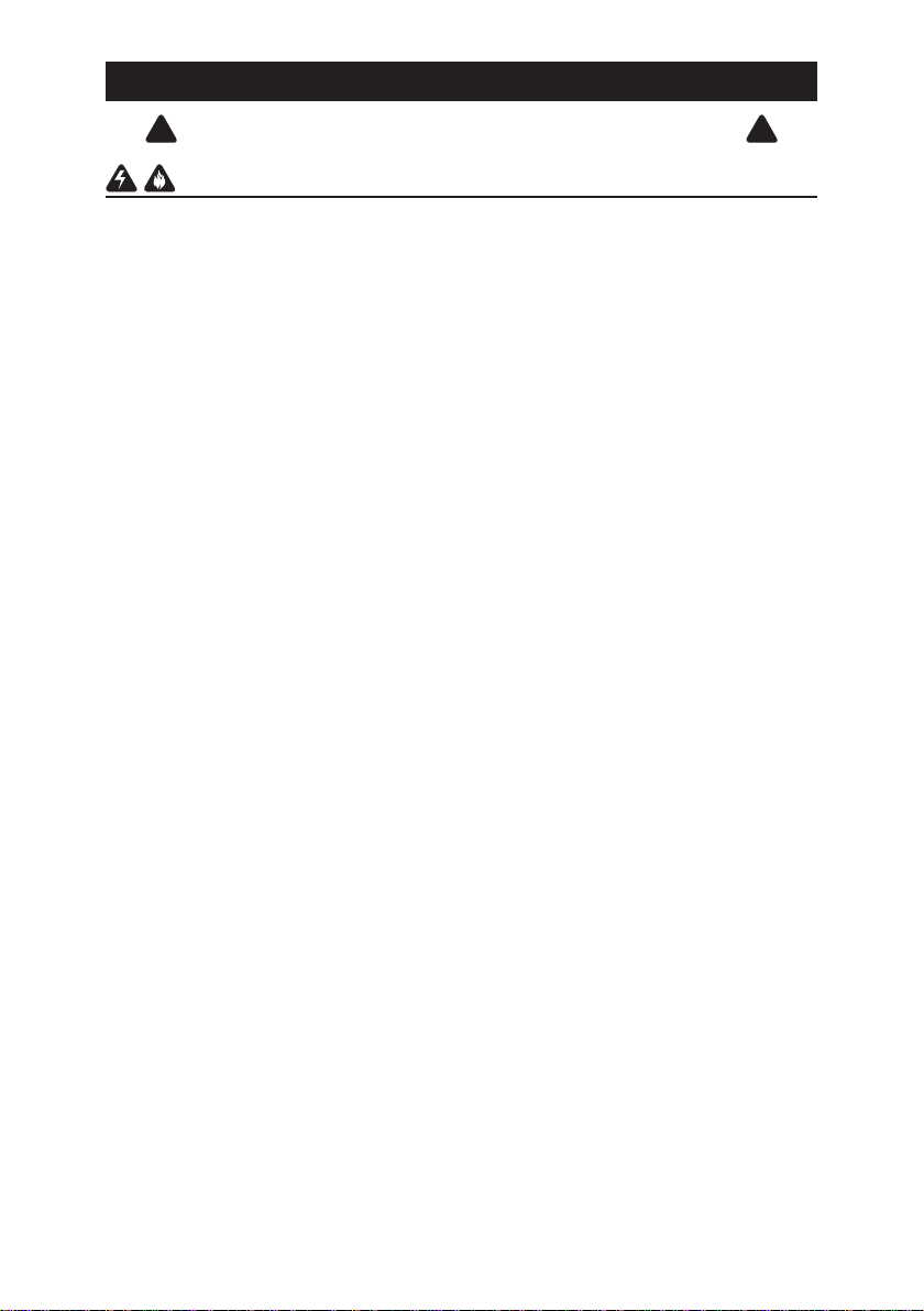
The hood is operated using the push buttons on the front panel.
Speed
Lamp
2 3 4
1
TIME/DELAY (2 Functions)
TIME SETTING
This button is used to set time when lighting and blower are not in use. Time is
displayed in a 12-hour cycle. To set time, press the push button (1) for 3 seconds.
The first two digits will flash. Use the blower push button (3) to increase, and the
lighting pushbutton (2) to decrease. Press the time/delay push button (1) again. The
last two digits will flash. Use the blower push button (3) to increase and the lighting
push button (2) to decrease. Press the time/delay button (1) again to confirm and
exit time setting mode.
DELAY SETTING
When blower is in use, this button is used as the delay off setting button. To set
delay, press the push button (1). The delay is factory set at 5 minutes, but can be
set from 1 up to 60 minutes. Use blower push button (3) to increase, and lighting
push button (2) to decrease. Countdown will be displayed on the LCD screen,
blower symbol will be activated, and the button (1) backlight will flash. Blower
will continue to operate for the programmed time and then will stop automatically
(delay-off setting does not affect lighting as it works independently). To cancel
delay function, press time/delay push button (1) again. The blower will continue
to operate and won’t stop until ON/OFF push button (4) is pressed. To turn delay
function and blower OFF at once, press ON/OFF push button (4). NOTE: Delay will
be reset if blower speed is modified during delay setting mode.
Timer
Power
nottub hsup rewolB )3nottub hsup yaleD/emiT )1
nottub hsup FFO/NO )4nottub hsup gnithgiL )2
LIGHTING
Press the lighting push button (2) once to turn the LCD screen on. To turn the
lights on, press the lighting push button (2) once more. Press it again to turn the
lights OFF. The LCD screen will turn off automatically after 15 seconds of inactivity
(blower and/or lights).
BLOWER
The blower push button (3) turns the blower on to one of three speed settings: LOW,
MEDIUM or HIGH. Press the blower (3) or ON/OFF (4) push button once to turn
the LCD screen on. Press the blower (3) or ON/OFF (4) push button once more to
turn the blower on at the last selected speed. Blower symbol will be activated. To
change the blower speed, press the blower push button (3) until the desired speed
is obtained. Press the ON/OFF push button (4) to turn the blower OFF. The last
speed used will be memorized. NOTE: When blower is turned on, 100% of power
level is activated for 1 to 2 seconds. It will then operate at the previous setting.
- 4 -
Page 5
!
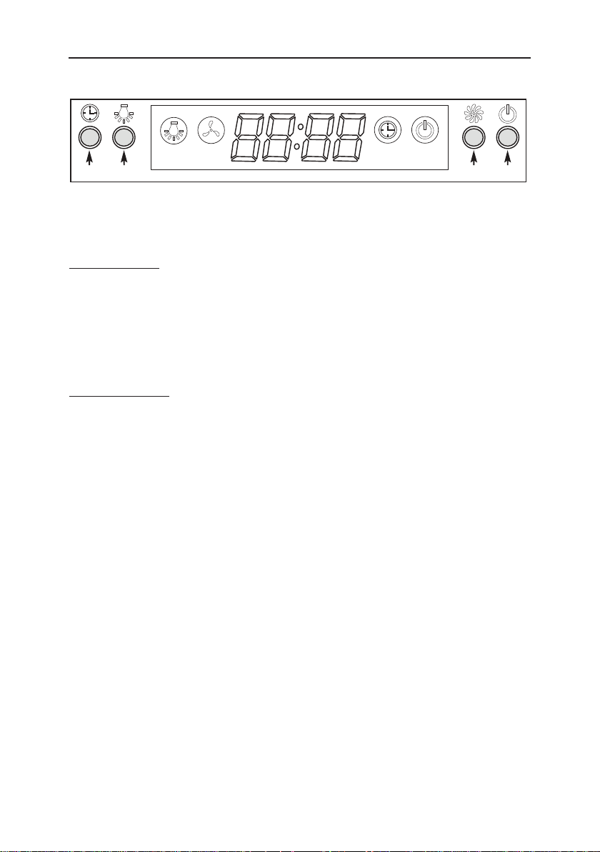
LIGHT BULBS
CAUTION
Bulbs may be hot. Always allow bulbs to
cool down before removing them.
This range hood requires four halogen bulbs
(Type JC, 12V, 20W Max, G-4 Base).
To change bulbs:
1. Remove light bulb cover by gently pushing
it upward and turning it counterclockwise.
2. Replace bulb.
3. Re-install light bulb cover by gently pushing it upward and turning it clockwise.
LIGHT BULB
COVER
CLEANING AND MAINTENANCE
Proper maintenance of the Range Hood will assure proper performance of the unit.
Motor
The motor is permanently lubricated and never needs oiling. If the motor bearings make
excessive or unusual noise, replace the motor with the exact service motor. The impeller
should also be replaced.
Grease Filter
The grease filter should be cleaned frequently. Use a warm detergent solution. Grease
filter is dishwasher safe.
Clean all-metal filters in the dishwasher using a non-phosphate detergent. Discoloration of
the filter may occur if using phosphate detergents, or as a result of local water conditions but this will not affect filter performance. This discoloration is not covered by the warranty.
See “INSTALL FILTERS” section for removal and installation instructions.
Non-ducted Recirculation Filter
The non-ducted recirculation filter should be changed every 6 months. Replace more
often if your cooking style generates extra grease, such as frying and wok cooking. See
“INSTALL FILTERS” section for removal and installation instructions.
Stainless Steel Cleaning
DO:
• Regularlywashwithcleanclothorrag
soaked with warm water and mild soap
or liquid dish detergent.
• Alwayscleaninthedirectionoforiginal
polish lines.
• Alwaysrinsewellwithclearwater(2or
3 times) after cleaning. Wipe dry completely.
• Youmayalsouseaspecializedhousehold stainless steel cleaner.
DON’T:
• Useanysteelorstainlesssteelwoolor
any other scrapers to remove stubborn
dirt.
• Useanyharshorabrasivecleansers.
• Allowdirttoaccumulate.
• Letplasterdustoranyotherconstruc-
tion residues reach the hood. During
construction/renovation, cover the range
hood to make sure no dust sticks to the
stainless steel surface.
Avoid: When choosing a detergent
• Anycleanersthatcontainbleachwillattackstainlesssteel
• Anyproductscontaining:chloride,fluoride,iodide,bromidewilldeterioratesurfacesrapidly.
• Anycombustibleproductsusedforcleaningsuchasacetone,alcohol,ether,benzol,etc.,
are highly explosive and should never be used close to a range.
- 5 -
Page 6
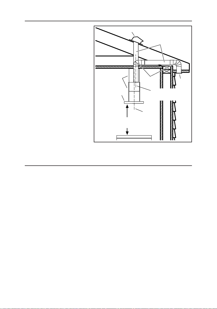
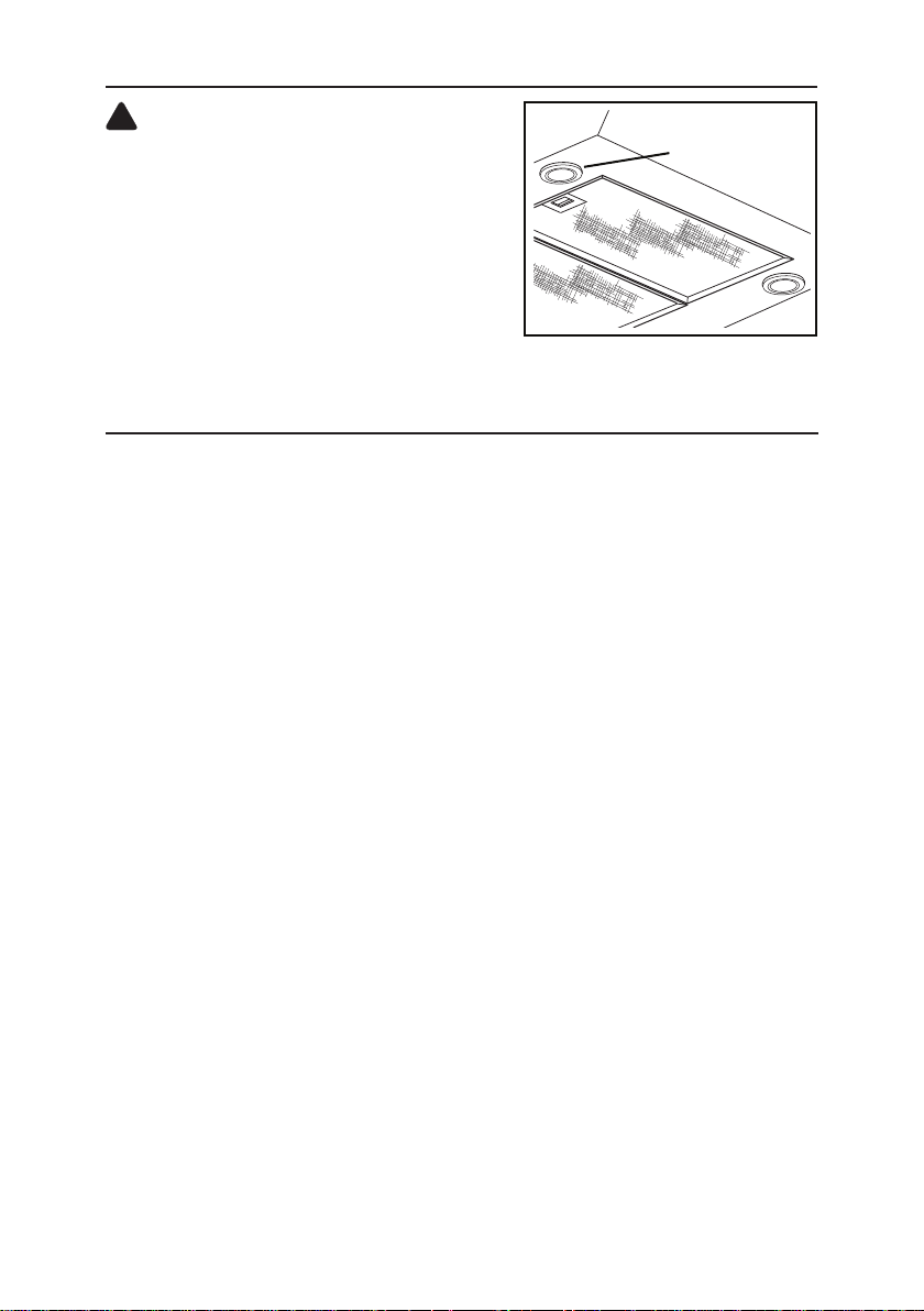
INSTALL THE DUCTWORK (Ducted Hoods Only)
1. Decide where the ductwork
will run between the hood
and the outside.
ROOF CAP
6” ROUND
DUCT
2. A straight, short duct
run will allow the hood to
perform most efficiently.
3. Long duct runs, elbows
and transitions will reduce
the performance of the
hood. Use as few of them
as possible. Larger ducting
may be required for best
performance with longer
DECORATIVE
FLUES
HOOD
6” ROUND
ELBOWS
DUCT CENTER LINE
(1-3/4” to rear of hood
centerline)
duct runs.
4. Install wall cap or roof
cap. Connect round metal
ductwork to cap and work
back towards the hood
24” TO 30” ABOVE
COOKING SUFACE
HOOD
CENTER
LINE
location. Use duct tape to
seal the joints between
ductwork sections.
MEASURE THE INSTALLATION
The minimum hood distance above cooktop MUST NOT BE LESS than 24”.
EAVE
VENT
A maximum of 30” above cooktop is highly recommended for best capture of
cooking impurities.
Distances over 30” are at the installer and users discretion; providing that the ceiling height permits.
NOTE:
On 7-ft 8-in. ceilings
Hood distance above cooktop is:
Minimum 24”, Maximum 30” (for ducted discharge).
Minimum 24”, Maximum 29” (for non-ducted discharge).
On 8-ft. ceilings
Hood distance above cooktop is:
Minimum 24”, Maximum 30” (for both ducted and non-ducted discharge).
On 9-ft. ceilings
Hood distance above cooktop is:
Minimum 30”, Maximum 30” (for both ducted and non-ducted discharge).
- 6 -
Page 7
PREPARE THE HOOD
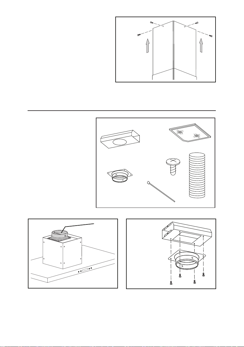
Unpack hood and check contents. You should receive:
1 - Hood
1 - Decorative Flue Assembly (2 pcs.)
1 - Damper / Duct Connector
1 - Ceiling Mounting Plate
8 - Angle Brackets
3 - Aluminum Grease Filters (installed in hood)
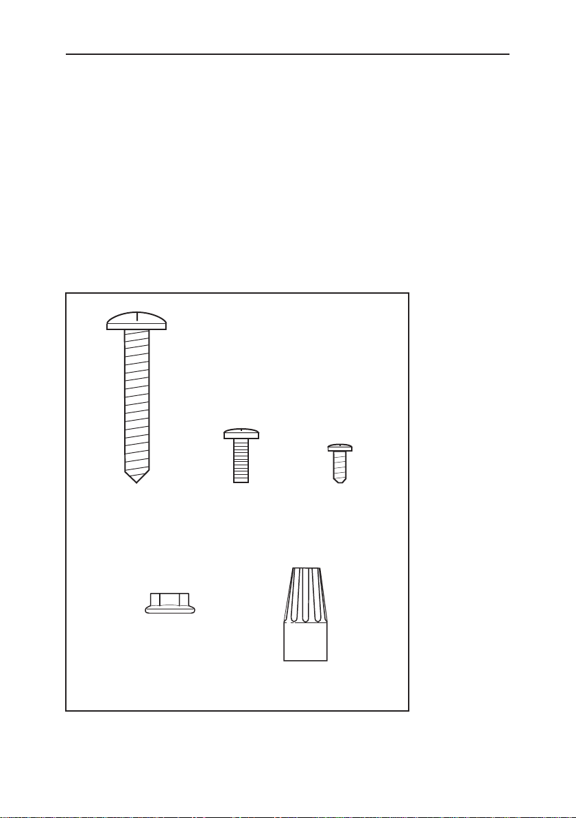
1 - Parts Bag containing:
8 - Mounting Screws (M6 x 40mm Pan Head)
46 - Machine Screws (M4 x 10mm Pan Head)
20 - Serrated Flange Nuts (M4)
8 - Sheet Metal Screws (M4 x 8mm Phillips Head)
3 - Wire Nuts
M6 x
40 mm
Serrated
M4
Flange
Nut
M4 x
10 mm
Machine
Screw
M4 x 8 mm
Sheet Metal
Wire Nut
- 7 -
Page 8
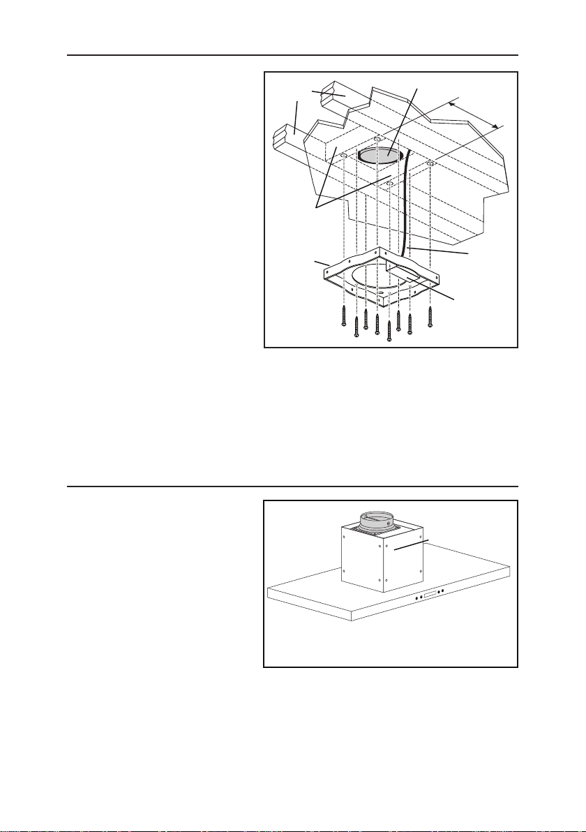
INSTALL CEILING SUPPORT
1. At hood location install 2 x
4 cross framing between
ceiling joists using dimensions
shown. Make sure framing
CEILING
JOISTS
6” ROUND DUCTWORK
8
¼
”
does not interfere with
electrical outlet box opening
in ceiling mounting plate.
2. Install house wiring and
ductwork.
3. Finish ceiling surface. Be sure
to mark the location of the
ceiling joists & cross framing.
Bring house wiring through
CROSS
FRAMING
CEILING
MOUNTING
PLATE
FRON T
HOUSE
WIRING
finished ceiling.
4. Remove cover from electrical
outlet box on ceiling
mounting plate. Pull house
(8) M6 x 40mm
WOOD
SCREWS
ELECTRICAL
OUTLET
BOX
wiring through hole on top
of mounting plate and into electrical outlet box. Secure house wiring cable to
mounting plate / electrical box with appropriate connector.
5. Install ceiling mounting plate with the side marked “front” at the desired hood
location. Secure using (8) M6 x 40mm wood screws. Make sure screws are
driven into the center of the framing for maximum strength.
PREPARE THE HOOD
1. Place the hood on flat
surface with protection
to insure the hood is not
damaged.
2. Attach the damper / duct
connector to the hood with
(4) M4 x 8mm pan head
sheet metal screws.
(4) M4 x 8mm
PAN HEAD
SHEET METAL
SCREWS
- 8 -
DAMPER / DUCT
CONNECTOR
Page 9
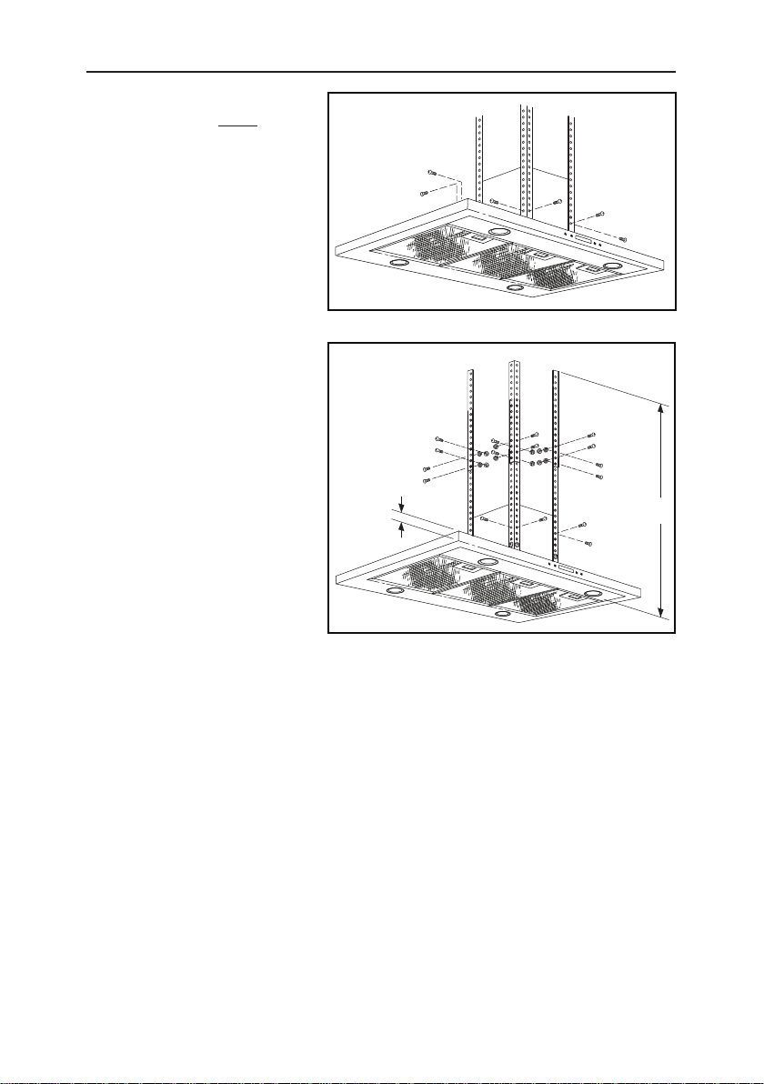
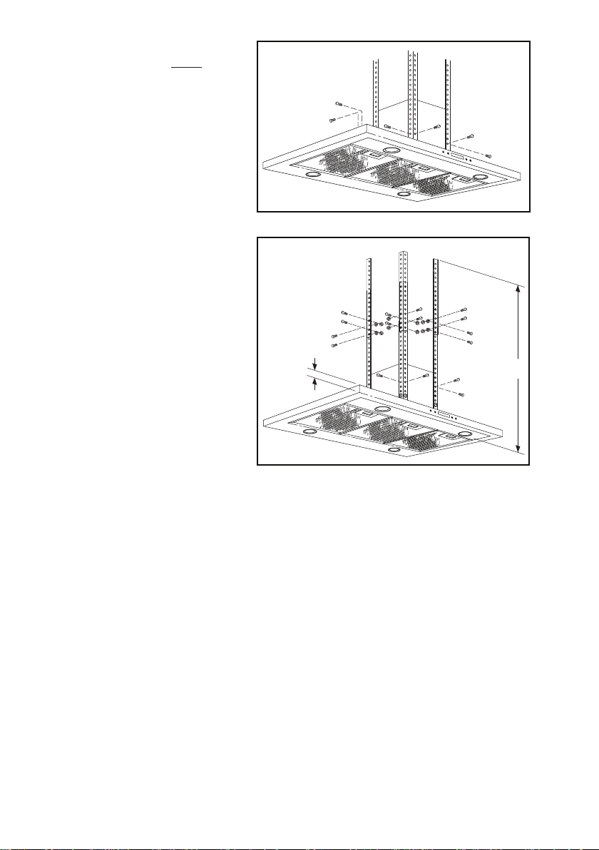
INSTALL THE HOOD (Ducted Installation Only)
1. Assemble (4) angle
brackets to the lower hood
mounting locations using
(8) M4 x 10mm pan head
machine screws (2 for each
angle bracket).
(8) M4 x 10mm
PAN HEAD
MACHINE
SCREWS
2. Determine dimension “H”
based upon ceiling height
and height of hood installation above cooktop:
7-FT. 8-IN. CEILING
(16) M4 x 10mm
PAN HEAD
MACHINE
SCREWS &
(16) M4
SERRATED
FLANGE NUTS
Hood 24” above cooktop
H = 32”
Hood 30” above cooktop
H = 30”
8-FT. CEILING
7
1
/
16
”
(8) M4 x 10mm
PAN HEAD
MACHINE
SCREWS
Hood 24” above cooktop
H = 36”
Hood 30” above cooktop
H = 30”
9-FT. CEILING
Hood 30” above cooktop
H = 42”
3. Attach the upper set of (4) angle brackets to the outside of the lower angle
brackets according to dimension “H”. Use (16) M4 x 10mm pan head machine
screws and (16) M4 serrated flange nuts (4 at each angle bracket connection).
4. Attach the angle bracket assemblies to the upper hood mounting locations
using (8) M4 x 10mm pan head machine screws (2 for each angle bracket).
H
- 9 -
Page 10
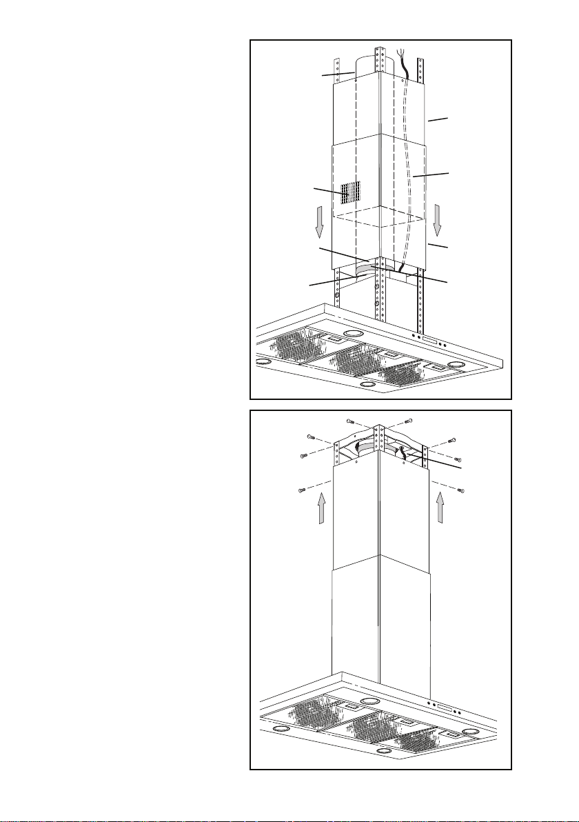
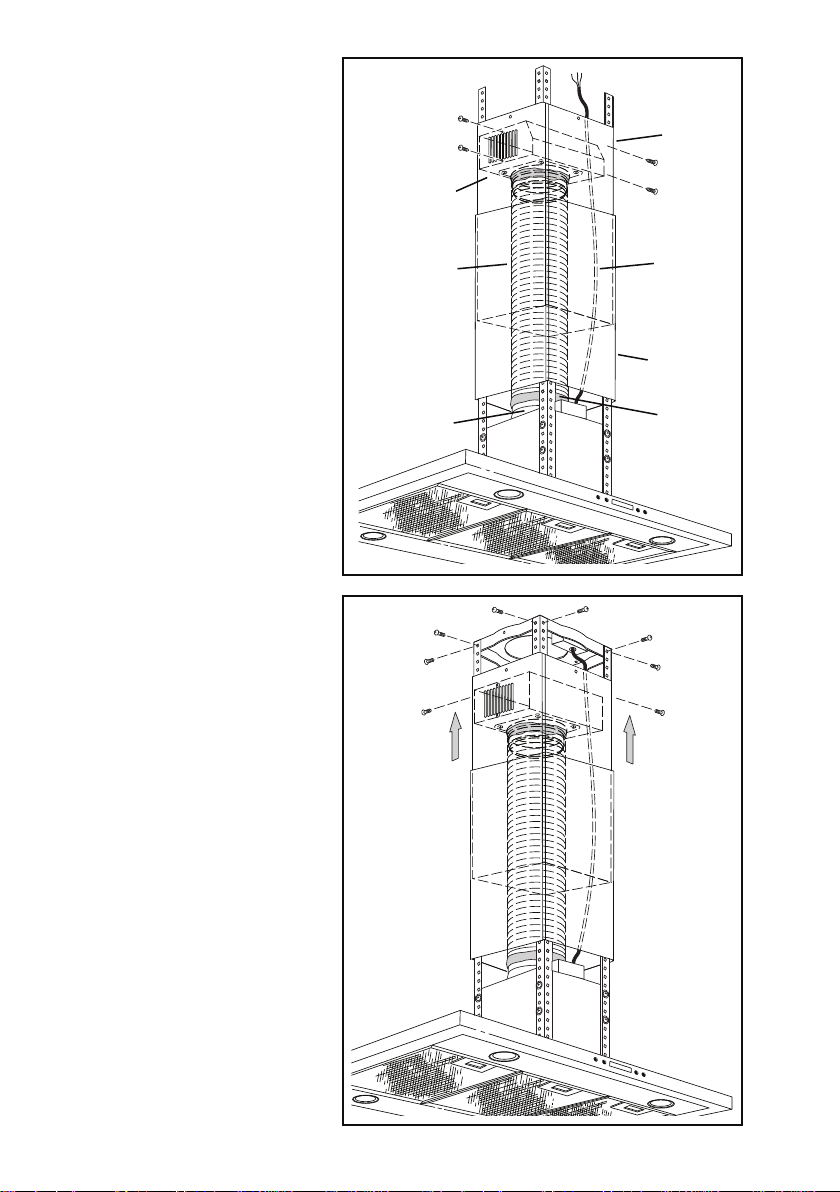
5. Measure the length of 6”
round metal duct required
from the damper / duct
connector to the ductwork
rough-in in the ceiling.
Connect the duct to the
damper / duct connector
and seal with duct tape.
6. Remove the protective
coating from the inner the
flue.
FOR CEILING HEIGHTS
7-FT. 8-IN. & 8-FT. ONLY:
Turn the inner flue so
that the louvers are at the
bottom.
FOR ALL CEILING
HEIGHTS:
Carefully slide the inner
flue down into the outer
flue. Slide the flues over
the angle brackets. Make
sure the side marked “front”
faces the control side of
the hood. Feed the power
cable up through the flues.
METAL
DUCT
LOUVERS
METAL
DUCT
DAMPER /
DUCT
CONNECTOR
FRONT
INNER
FLUE
POWER
CABLE
OUTER
FLUE
DUCT
TAPE
7. Attach the hood assembly
to the ceiling bracket using
(8) M4 x 10mm machine
screws (2 for each support
leg).
8. Connect metal duct to
ceiling duct and seal with
duct tape.
9. Connect power cable to
house wiring inside of
electrical outlet box. Black
to Black, White to White,
and Green to Green or
Bare wires. Secure power
cable to wiring box with
appropriate connector and
re-attach outlet box cover.
(8) M4 x 10mm
PAN HEAD
MACHINE
SCREWS
- 10 -
POWER
CABLE
Page 11
10. Slide the inner flue up to
the ceiling and secure with
(4) M4 x 8mm sheet metal
screws.
11. Remove the protective
coating from the hood and
the outer flue.
(4) M4 x 8mm
SHEET METAL
SCREWS
INSTALL THE HOOD (Non-Ducted Installation Only)
NOTE:
Non-ducted installations
require Non-Duct
kit; model ANK
IBF4
(purchased separately).
Do not use plastic or rigid
metal duct.
FRONT
NON-DUCT
PLENUM
NON-DUCT PLENUM
COLLAR
NON-DUCTED
RECIRCULATION
FILTER
8 MOUNTING
SCREWS
(M4 x 8
Pan Head
Sheet Metal)
2 TIE
WRAPS
FLEXIBLE DUCT
DAMPER
FLAPS
1. Remove the damper flaps from
the damper / duct connector and
discard flaps.
FRONT
(4) M4 x 8mm
SHEET METAL
SCREWS
2. Attach non-duct collar to non-duct
plenum using (4) M4 x 8mm sheet
metal screws.
- 11 -
Page 12
3. Assemble (4) angle
brackets to the lower hood
mounting locations using
(8) M4 x 10mm pan head
machine screws (2 for each
angle bracket).
(8) M4 x 10mm
PAN HEAD
MACHINE
SCREWS
4. Determine dimension “H”
based upon ceiling height
and height of hood installation above cooktop:
7-FT. 8-IN. CEILING
(16) M4 x 10mm
PAN HEAD
MACHINE
SCREWS &
(16) M4
SERRATED
FLANGE NUTS
Hood 30” above cooktop
H = 30”
Hood 29” above cooktop
H = 27”
8-FT. CEILING
7
1
/
16
”
(8) M4 x 10mm
PAN HEAD
MACHINE
SCREWS
Hood 24” above cooktop
H = 36”
Hood 30” above cooktop
H = 30”
9-FT. CEILING
Hood 30” above cooktop
H = 42”
5. Attach the upper set of (4) angle brackets to the outside of the lower angle
brackets according to dimension “H”. Use (16) M4 x 10mm pan head machine
screws and (16) M4 serrated flange nuts (4 at each angle bracket connection).
6. Attach the angle bracket assemblies to the upper hood mounting locations
using (8) M4 x 10mm pan head machine screws (2 for each angle bracket).
H
- 12 -
Page 13
7. Measure the length of
6” round flexible duct
required from the damper
/ duct connector to the
ductwork rough-in in
the ceiling. Connect the
duct to the damper / duct
connector, secure with
tie wrap and seal with
duct tape.
8. Attach the aluminum
flexible duct to the nonduct plenum collar. Make
sure non-duct plenum
“front” is facing front of
hood. Secure with tie
wrap and seal with duct
tape.
9. Remove the protective
coating from the inner
the flue. Turn the inner
flue so that the louvers
are at the top. Carefully
slide the inner flue down
into the outer flue. Slide
the flues over the angle
brackets. Make sure the
side marked “front” faces
the control side of the
hood. Feed the power
cable up through the
flues.
10. Pull the inner flue up
and attach the non-duct
plenum with collar to
the upper flue using (4)
M4 x 8mm sheet metal
screws.
11. Attach the hood
assembly to the ceiling
bracket using (8) M4 x
10mm machine screws
(2 for each support leg).
12. Connect power cable to
house wiring. Black to
Black, White to White,
and Green to Green
or Bare wires. Secure
power cable to wiring
box with appropriate
connector.
(4) M4 x 8mm
SHEET METAL
SCREWS
NON-DUCT
PLENUM
FLEXIBLE
DUCT
DAMPER /
DUCT
CONNECTOR
(8) M4 x 10mm
PAN HEAD
MACHINE
SCREWS
- 13 -
FRONT
FRONT
INNER
FLUE
POWER
CABLE
OUTER
FLUE
DUCT
TAPE
Page 14
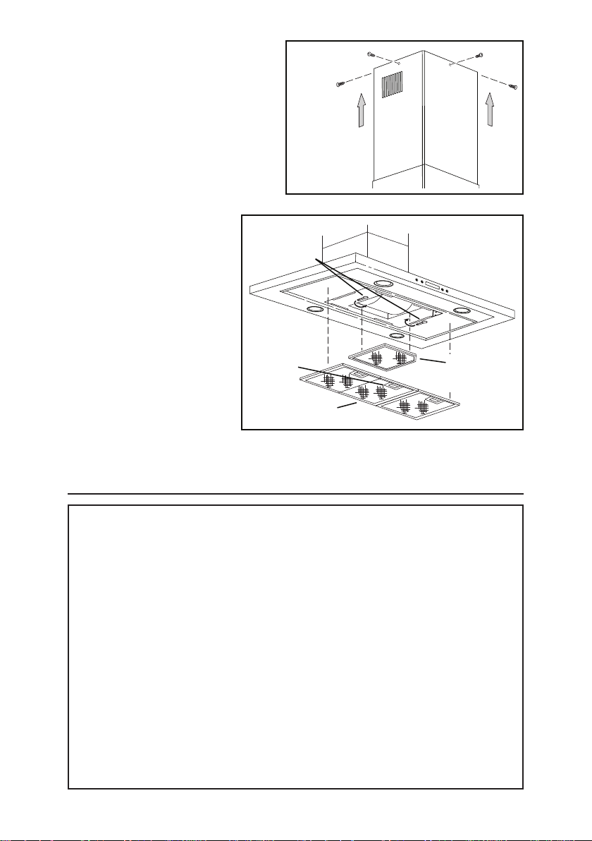
13. Slide the inner flue up to the
ceiling and secure with (4) M4
x 8mm sheet metal screws.
14. Remove the protective coating
from the hood and the outer
flue.
(4) M4 x 8mm
SHEET
METAL
SCREWS
15. Remove the grease
filters by pulling down
the metal latch tab
and tilting the filters
NON-DUCT
FILTER
MOUNTING
TABS
downward to remove.
16. Install the non-duct
recirculation filter as
shown. Turn mounting
tabs on hood to secure
filter.
1 7. Reinstall grease filters
by aligning rear filter
tabs with slots in the
hood. Pull down the
metal latch tab, push
METAL
LATCH
GREASE
FILTERS
NON-DUCT
RECIRCULATION
FILTER
filter into position and
release. Make sure filters are securely engaged after installation.
WARRANTY
Broan-NuTone LLC (Broan-NuTone) warrants to the original consumer purchaser of Best products that such products
will be free from defects in materials or workmanship for a period of one year from the date of original purchase. THERE
ARE NO OTHER WARRANTIES, EXPRESS OR IMPLIED, INCLUDING, BUT NOT LIMITED TO, IMPLIED WARRANTIES OR MERCHANT ABILITY OR FITNESS FOR A PARTICULAR PURPOSE.
During this one-year period, Broan-NuTone will, at its option, repair or replace, without charge, any product or part which
is found to be defective under normal use and service.
THIS WARRANTY DOES NOT EXTEND TO FLUORESCENT LAMP STARTERS, TUBES, HALOGEN AND INCANDESCENT BULBS, FUSE, FILTERS, DUCTS, ROOF CAPS, WALL CAPS AND OTHER ACCESSORIES FOR DUCTING.
This warranty does not cover (a) normal maintenance and service or (b) any products or parts which have been subject
to misuse, negligence, accident, improper maintenance or repair (other than by Broan-NuTone), faulty installation or
installation contrary to recommended installation instructions.
The duration of any implied warranty is limited to the one-year period as specified for the express warranty. Some states
do not allow limitation on how long an implied warranty lasts, so the above limitation may not apply to you.
BROAN-NUTONE’S OBLIGATION TO REPAIR OR REPLACE, AT BROAN-NUTONE’S OPTION, SHALL BE THE
PURCHASER’S SOLE AND EXCLUSIVE REMEDY UNDER THIS WARRANTY. BROAN-NUTONE SHALL NOT BE LIABLE FOR INCIDENTAL, CONSEQUENTIAL OR SPECIAL DAMAGES ARISING OUT OF OR IN CONNECTION WITH
PRODUCT USE OR PERFORMANCE. Some states do not allow the exclusion or limitation of incidental or consequential
damages, so the above limitation or exclusion may not apply to you.
This warranty gives you specific legal rights, and you may also have other rights, which vary from state to state. This
warranty supersedes all prior warranties.
To qualify for warranty service, you must (a) notify Broan-NuTone at the address stated below or telephone number stated
below, (b) give the model number and part identification and (c) describe the nature of any defect in the product or part.
At the time of requesting warranty service, you must present evidence of the original purchase date.
In USA - BEST®, 926 W. State Street, Hartford, WI 53027 (800-558-1711)
In Canada - BEST®, 550 Lemire Blvd., Drummondville, QC J2C 7W9 (866-737-7770)
www.BestRangeHoods.com
ONE YEAR LIMITED WARRANTY FOR BEST PRODUCTS
- 14 -
Page 15

SERVICE PARTS
KEY PART NO. DESCRIPTION QTY.
1 S99528360 Decorative Upper and Lower Flues 1
2 S99528361 Motor / Blower Assembly 1
3 S99526975 Light Socket Assembly 4
4 S99527010 Light Trim Ring / Lens Assembly 4
5 S99527660 User Interface Assembly 1
6 S99527665 Control Board 1
7 S97018908 Aluminum Grease Filters 3
8 S99527023 Non-Duct Recirculation Filter 1
9 S99526983 Damper / Duct Connector 1
10 S99526984 6” Dia. Expandable Flexible Aluminum Duct 1
11 S99528362 Non-Duct Plenum Assembly 1
12 S99528363 Angle Mounting Bracket 8
13 S99528364 Ceiling Mounting Bracket w/ Outlet Box 1
S99527662 Capacitor (not shown) 1
S99527132 Parts Bag (not shown) 1
S99528459 Non-Duct Filter Clips (not shown) 1
S99527011 Transformer (not shown) 1
Order service parts by Part No. - not by Key No.
- 15 -
Page 16

SERVICE PARTS
11
13
10
1
12
Replacement parts can be
ordered on our website:
www.BestRangeHoods.com
9
6
8
3
4
2
5
8
7
- 16 -
99528359F
Page 17

Modèle IBF4I36SB
Aux États-Unis - BEST® Hartford, Wisconsin
ENREGISTREZ VOTRE PRODUIT EN LIGNE À : www.BestRangeHoods.com/register
Pour de plus amples informations, visitez www.BestRangeHoods.com
Page 18

LIRE CES DIRECTIVES ET LES CONSERVER
!
!
POUR USAGE DOMESTIQUE SEULEMENT
AVERTISSEMENT
AFIN DE RÉDUIRE LES RISQUES D’INCENDIE, DE DÉCHARGES ÉLECTRIQUES
OU DE BLESSURES CORPORELLES, VEUILLEZ OBSERVER LES DIRECTIVES
SUIVANTES :
1. N’utilisez cet appareil que de la manière prévue par le fabricant. Si vous avez des
questions, communiquez avec le fabricant à l’adresse ou au numéro de téléphone
indiqués dans la garantie.
2. Avant de procéder à l’entretien ou au nettoyage de l’appareil, coupez l’alimentation
du panneau électrique et verrouillez l’interrupteur principal afin d’empêcher que le
courant ne soit accidentellement rétabli. S’il est impossible de verrouiller l’interrupteur
principal, fixez solidement un message d’avertissement, par exemple une étiquette,
sur le panneau électrique.
3. L’installation et les branchements électriques doivent être effectués par un personnel
compétent, conformément aux normes et aux codes en vigueur, y compris les normes
et les codes du bâtiment relatifs à la résistance au feu.
4. Pour éviter les refoulements, l’apport d’air doit être suffisant pour brûler les gaz produits
par les appareils à combustion et les évacuer dans le conduit de fumée (cheminée).
Respectez les directives du fabricant de l’appareil de chauffage et les normes de
sécurité, notamment celles publiées par la National Fire Protection Association
(NFPA), l’American Society for Heating, Refrigeration and Air Conditioning Engineers
(ASHRAE) et les codes des autorités locales.
5. Veillez à ne pas endommager le câblage électrique ou d’autres équipements non
apparents lors de la découpe ou du perçage du mur ou du plafond.
6. Les ventilateurs canalisés doivent toujours rejeter l’air à l’extérieur.
7. N’utilisez pas de commande de régime à semi-conducteurs avec cet appareil.
8. Pour réduire les risques d’incendie, utilisez seulement des conduits en acier.
9. Cet appareil doit être relié à une mise à la terre.
POUR RÉDUIRE LES RISQUES D’INCENDIE CAUSÉS PAR DE LA GRAISSE SUR
LE PLAN DE CUISSON :
a) Ne laissez jamais les éléments de surface allumés à haute température. Les
débordements peuvent causer de la fumée et occasionner des écoulements de
graisse inflammables. L’huile doit être chauffée graduellement à basse ou à moyenne
température.
b) Mettez toujours la hotte en MARCHE lors de la cuisson à feu vif ou lors de la cuisson
d’aliments à flamber (crêpes Suzette, cerises jubilé, bœuf au poivre flambé).
c) Nettoyez souvent la hotte. Ne laissez pas la graisse s’accumuler sur le ventilateur ou
les filtres.
d) Utilisez des casseroles de dimension appropriée. Utilisez toujours une batterie de
cuisine adaptée à la dimension de la surface chauffante.
OBSERVEZ LES CONSIGNES SUIVANTES AFIN DE RÉDUIRE LES RISQUES DE
BLESSURES CORPORELLES EN CAS D’INCENDIE CAUSÉ PAR DE LA GRAISSE
SUR LE PLAN DE CUISSON :*
1. ÉTOUFFEZ LES FLAMMES à l’aide d’un couvercle étanche, d’une tôle à biscuits
ou d’un plateau en métal puis éteignez le brûleur. FAITES ATTENTION DE NE PAS
- 18 -
Page 19

!
VOUS BRÛLER. SI LES FLAMMES NE S’ÉTEIGNENT PAS IMMÉDIATEMENT,
QUITTEZ LES LIEUX ET APPELEZ LE SERVICE DES INCENDIES.
2. NE SOULEVEZ JAMAIS UNE CASSEROLE EN FLAMMES – vous pourriez
vous brûler.
3. N’UTILISEZ PAS D’EAU, ni de linges ou de serviettes mouillés – une violente explosion
de vapeur pourrait survenir.
4. Utilisez un extincteur SEULEMENT si :
A. Vous savez qu’il est de classe ABC et vous connaissez déjà son mode
de fonctionnement.
B. L’incendie n’est pas très important et ne se propage pas.
C. Vous avez déjà téléphoné au service des incendies.
D. Vous pouvez combattre l’incendie en faisant dos à une sortie.
* Conseils tirés de la publication de la NFPA « Kitchen Fire Safety Tips ».
ATTENTION
1. Pour usage intérieur seulement.
2. Pour ventilation générale uniquement. N’utilisez pas cet appareil pour évacuer des
matières ou des vapeurs dangereuses ou explosives.
3. Pour ne pas endommager les roulements du moteur, déséquilibrer les pales ou les
rendre bruyantes, protégez l’appareil de la poussière de plâtre, de construction, etc.
4. N’utilisez pas cette hotte au-dessus d’un appareil de cuisson dépassant
60 000 BTU/heure car le moteur du ventilateur s’arrêtera par intermittence.
5. Le moteur de la hotte est muni d’un dispositif de protection thermique qui coupe
automatiquement le moteur en cas de surchauffe. Il se remet en marche lorsqu’il a
refroidi. Faites réparer la hotte si le moteur continue à fonctionner par intermittence.
6. Pour mieux capter les vapeurs de cuisson, le bas de la hotte DOIT ÊTRE AU MINIMUM
à 61 cm (24 po) et au maximum à 76 cm (30 po) au-dessus de la surface de cuisson.
7. Il est recommandé que les installateurs soient deux, compte tenu de la taille de
cette hotte.
8. Pour réduire les risques d’incendie et évacuer l’air correctement, assurez-vous qu’il
est canalisé à l’extérieur. Névacuez pas l’air dans des espaces enfermés par des
murs ou un plafond ou dans un grenier, un vide sanitaire ou un garage.
9. Prenez garde en installant la cheminée décorative et la hotte, car elles peuvent
comporter des bords tranchants.
10. Veuillez lire l’étiquette de spécifications du produit pour obtenir plus de renseignements,
notamment sur les exigences.
- 19 -
Page 20

FONCTIONNEMENT
La hotte fonctionne à l’aide des boutons-poussoirs situés sur la face avant.
Vitesse
Éclairage
2 3 4
1
1) Bouton heure / arrêt différé
2) Bouton d’éclairage
HEURE / ARRÊT DIFFÉRÉ (2 fonctions)
RÉGLAGE DE L’HEURE
Ce bouton permet de régler l’heure lorsque l’éclairage et le ventilateur ne sont pas
utilisés. L’heure est affichée en cycle de 12 heures. Pour régler l’heure, appuyez sur le
bouton (1) pendant trois secondes. Les deux premiers chiffres se mettent à clignoter.
Utilisez le bouton du ventilateur (3) pour avancer et le bouton d’éclairage (2) pour
reculer. Appuyez de nouveau sur le bouton heure / arrêt différé (1). Les deux derniers
chiffres se mettent à clignoter. Utilisez le bouton du ventilateur (3) pour avancer et le
bouton d’éclairage (2) pour reculer. Appuyez de nouveau sur le bouton heure / arrêt
différé (1) pour confirmer et quitter le mode de réglage de l’heure.
RÉGLAGE DE L’ARRÊT DIFFÉRÉ
Lorsque le ventilateur est en marche, ce bouton permet de retarder l’arrêt du ventilateur.
Pour régler l’arrêt différé, appuyez sur le bouton (1). Par défaut, l’arrêt différé est réglé à
5 minutes mais il peut aller jusqu’à 60 minutes. Utilisez le bouton du ventilateur (3) pour
retarder l’arrêt et le bouton d’éclairage (2) pour l’avancer. Le compte à rebours s’affiche
sur l’écran ACL, le symbole du ventilateur est activé et le rétroéclairage du bouton
(1) clignote. Le ventilateur continuera de fonctionner pendant le temps programmé
puis s’arrêtera automatiquement (l’arrêt différé ne concerne pas l’éclairage car il est
indépendant). Pour annuler la fonction d’arrêt différé, appuyez de nouveau sur le bouton
(1). Le ventilateur continuera de fonctionner et ne s’arrêtera pas tant que vous n’aurez
pas appuyé sur le bouton MARCHE / ARRÊT (4). Pour annuler la fonction d’arrêt différé
et arrêter le ventilateur du même coup, appuyez sur le bouton MARCHE / ARRÊT (4).
REMARQUE : Le délai sera rétabli si la vitesse du ventilateur est modifiée pendant le
réglage du mode d’arrêt différé.
Alimentation
Minuterie
3) Bouton du ventilateur
4) Bouton MARCHE / ARRÊT
ÉCLAIRAGE
Appuyez une fois sur le bouton d’éclairage (2) pour allumer l’écran ACL. Pour allumer
les lumières, appuyez sur le bouton d’éclairage (2) une fois de plus. Appuyez de
nouveau pour éteindre des lumières. L’écran ACL s’éteint automatiquement après
15 secondes d’inactivité (ventilateur et/ou lumières).
VENTILATEUR
Le bouton du ventilateur (3) met le ventilateur en marche à l’un des trois réglages de
vitesse : LENT, MOYEN ou ÉLEVÉ. Appuyez une fois sur le bouton du ventilateur (3) ou
sur le bouton MARCHE / ARRÊT (4) pour allumer l’écran ACL. Appuyez une fois de
plus sur le bouton du ventilateur (3) ou sur le bouton MARCHE / ARRÊT (4) pour
actionner le ventilateur à la dernière vitesse sélectionnée. Le symbole du ventilateur est
activé. Pour modifier la vitesse du ventilateur, appuyez sur le bouton du ventilateur (3)
jusqu’à l’obtention de la vitesse voulue. Pour arrêter le ventilateur, appuyez sur le bouton
MARCHE / ARRÊT (4). La dernière vitesse utilisée est mémorisée. REMARQUE :
Lors de la mise en marche du ventilateur, son niveau de puissance est activé à 100 %
pendant 1 à 2 secondes. Puis, il fonctionne à la vitesse préalablement réglée.
- 20 -
Page 21

!
AMPOULES
ATTENTION
Les ampoules peuvent être très chaudes.
Laissez toujours les ampoules refroidir avant
de les enlever.
Cette hotte requiert quatre ampoules halogènes
(type JC, 12V, 20W max, base G4).
Pour remplacer les ampoules :
1. Enlevez le couvercle des ampoules en le
poussant délicatement vers le haut et en le
tournant dans le sens antihoraire.
2. Remplacez la ou les ampoules.
3. Replacez le couvercle en le poussant délicatement vers le haut et en le tournant dans le
sens horaire.
COUVERCLE
DES AMPOULES
NETTOYAGE ET ENTRETIEN
Un entretien adéquat de la hotte assurera son bon fonctionnement.
Moteur
Le moteur est lubrifié en permanence et n’a pas besoin d’être huilé. Si les roulements du moteur
sont anormalement bruyants, remplacez le moteur exactement par le même modèle. La roue
à ailettes doit aussi être remplacée.
Filtre à graisses
Le filtre à graisses doit être nettoyé fréquemment. Utilisez une solution tiède de détergent. Le
filtre à graisses est lavable au lave-vaisselle.
Nettoyez les filtres entièrement métalliques au lave-vaisselle avec un détergent sans phosphate.
Une décoloration du filtre peut se produire si des détergents phosphatés sont utilisés et selon
les conditions locales de l’eau, sans toutefois affecter le rendement du filtre. Cette décoloration
n’est pas couverte par la garantie.
Voir la section « INSTALLATION DES FILTRES » pour leur enlèvement et leur pose.
Filtre de recirculation pour installation sans conduit
Dans une installation sans conduit, le filtre de recirculation doit être remplacé tous les six mois.
Remplacez-le plus souvent si le type de cuisine produit plus de graisses, telle que la friture
et la cuisson au wok. Voir la section « INSTALLATION DES FILTRES » pour leur enlèvement
et leur pose.
Nettoyage de l’acier inoxydable
À FAIRE :
• Régulièrement,nettoyeztouteslessurfaces
avec un chiffon propre imbibé d’eau tiède et
de savon doux ou de liquide à vaisselle.
• Nettoyeztoujoursdanslesensdeslignesdu
poli original.
• Rinceztoujoursàl’eau propre(2ou3 fois)
après le nettoyage. Séchez complètement en
essuyant.
• Vouspouvezégalementutiliserunnettoyant
spécial pour acier inoxydable.
À éviter : Lors du choix d’un détergent
• Toutnettoyantcontenantdel’eaudejavelattaqueral’acierinoxydable.
• Toutproduitcontenant:duchlore,dufluor,del’iodeoudubromedétériorerarapidementlessurfaces.
• Toutproduitcombustibleutilisépourlenettoyagecommel’acétone,l’alcool,l’éther,lebenzol,etc.,
est hautement explosif et ne doit jamais être utilisé à proximité d’une hotte.
À NE PAS FAIRE :
• N’utilisezpas de laine d’acier ordinaireni
de laine d’acier inoxydable ou tout genre de
grattoir pour déloger la saleté.
• N’utilisezaucunnettoyantpuissantouabrasif.
• Nelaissezpaslasaletés’accumuler.
• Protégezlahottedelapoussièredeplâtreou
de tout autre résidu de construction. Pendant
des travaux de construction ou de rénovation,
couvrez la hotte pour empêcher la poussière
de toucher aux surfaces d’acier inoxydable.
- 21 -
Page 22

INSTALLATION DES CONDUITS (hottes avec conduits
seulement)
1. Planifiez la pose du conduit
en déterminant son tracé
entre la hotte et l’extérieur
de la maison.
2. Un tracé droit et court permet
à la hotte d’être plus efficace.
3. Des conduits longs, des
coudes et des transitions
réduisent l’efficacité de la
hotte. N’en utilisez que le
moins possible. Pour plus
d’efficacité, des conduits
plus gros peuvent être
nécessaires si le parcours
est trop long.
4. Installez le capuchon mural
ou de toit. Connectez un
conduit rond en métal au
capuchon en progressant
vers la hotte. Scellez les
joints avec du ruban à
conduit à chaque section.
CAPUCHON DE TOIT
CONDUIT
DÉCORATIF
HOTTE
61 CM À 76 CM
(24 À 30 PO)
AU-DESSUS DE LA
SURFACE DE CUISSON
CONDUIT ROND DE
15,2 CM (6 PO)
COUDES
RONDS DE
15,2 CM (6 PO)
LIGNE CENTRALE DU
CONDUIT (4,4 cm [1 3/4 po]
à l’arrière de la ligne centrale
de la hotte)
LIGNE
CENTRALE
DE LA HOTTE
ÉVENT
D’AVANTTOIT
MESURES DE L’INSTALLATION
La distance minimale de la hotte au-dessus de la surface de cuisson NE DOIT PAS
ÊTRE INFÉRIEURE à 61 cm (24 po).
Un maximum de 76 cm (30 po) est également fortement recommandé pour mieux
capter les vapeurs de cuisson.
Une distance de plus de 76 cm (30 po) est laissée à la discrétion de l’installateur et
des utilisateurs si la hauteur du plafond le permet.
REMARQUE :
Pour les plafonds de 2,3 m (7 pi - 8 po)
La distance de la hotte au-dessus de la surface de cuisson est :
Au minimum 61 cm (24 po), au maximum 76 cm (30 po) (pour une sortie avec conduits)
Au minimum 61 cm (24 po), au maximum 74 cm (29 po) (pour une sortie sans conduits)
Pour les plafonds de 2,4 m (8 pi)
La distance de la hotte au-dessus de la surface de cuisson est :
Au minimum 61 cm (24 po), au maximum 76 cm (30 po) (pour une sortie avec ou
sans conduits)
Pour les plafonds de 2,7 m (9 pi)
La distance de la hotte au-dessus de la surface de cuisson est :
Au minimum 76 cm (30 po), au maximum 76 cm (30 po) (pour une sortie avec ou
sans conduits).
- 22 -
Page 23

PRÉPARATION DE LA HOTTE
Déballez la hotte et vérifiez le contenu de la boîte.
Celle-ci doit contenir les éléments suivants :
1 - Hotte
1 - Conduit décoratif de cheminée (2 pièces)
1 - Clapet / raccord de conduit
1 - Plaque de fixation au plafond
8 - Supports angulaires
3 - Filtres à graisse en aluminium (installés dans la hotte)
1 - Sac de pièces contenant :
8 - Vis de montage (M6 x 40 mm à tête cylindrique)
46 - Vis mécanique (M4 x 10 mm à tête cylindrique)
20 - Écrous à embase dentelée (M4)
8 - Vis à tôle (M4 x 8 mm à tête cruciforme)
3 - Serre-fils
M6 x
40 mm
à embase
dentelée
Écrou
M4
Vis mécanique
M4 x 10 mm
- 23 -
Vis à tôle
M4 x 8 mm
Serre-fils
Page 24

INSTALLATION DU SUPPORT AU PLAFOND
1. À l’emplacement choisi pour la
hotte, installez des entretoises
de 2 x 4 entre les solives du
plafond selon les dimensions
SOLIVES
CONDUIT ROND DE 15,2 CM (6 PO)
(8
21 cm
¼
po)
illustrées. Assurez-vous que
la charpente n’obstrue pas
l’ouverture du boîtier électrique
de la plaque de fixation
au plafond.
2. Installez le câblage et
les conduits.
3. Finissez la surface du plafond.
Marquez la position des solives
et des entretoises. Enfilez le
ENTRETOISE
PLAQUE DE
FIXATION AU
PLAFOND
FRON T
CÂBLAGE
DE LA MAISON
câblage électrique au travers
de la surface finie du plafond.
4. Enlevez le couvercle de la
(8) VIS À BOIS
M6 X 40 MM
BOÎTE
ÉLECTRIQUE
boîte électrique sur la plaque
de fixation au plafond. Tirez le
câble à travers l’ouverture de la
plaque de fixation jusque dans la boîte électrique. Fixez le câble à la plaque /
boîte électrique avec le connecteur approprié.
5. Installez la plaque de fixation au plafond, le côté marqué « front » (avant) orienté
dans la bonne direction. Fixez la plaque avec (8) vis à bois M6 x 40 mm. Assurezvous que les vis sont enfoncées au centre des pièces de cadrage pour une
solidité maximale.
PRÉPARATION DE LA HOTTE
1. Placez la hotte sur une surface
plane et protégée pour éviter
d’abîmer la hotte.
2. Fixez le clapet / raccord de
conduit à la hotte à l’aide de
(4) vis à tôle à tête cylindrique
M4 x 8 mm.
(4) VIS À
TÔLE À TÊTE
CYLINDRIQUE
M4 x 8 MM
- 24 -
CLAPET / RACCORD
DE CONDUIT
Page 25

INSTALLATION DE LA HOTTE (installation avec
conduits uniquement)
1. Assemblez les (4) supports
angulaires sur la partie
inférieure de la hotte avec
(8) vis mécaniques à tête
cylindrique M4 x 10 mm
(2 pour chaque support
angulaire).
(8) VIS
MÉCANIQUES
À TÊTE
CYLINDRIQUE
M4 x 10 MM
2. Déterminez la dimension « H »
d’après la hauteur du plafond
et celle de l’emplacement de
la hotte au-dessus du plan
de cuisson :
PLAFOND DE 2,3 M
(7 PI - 8 PO)
Hotte à 61 cm (24 po)
au-dessus de la surface
de cuisson
H = 81 cm (32 po)
Hotte à 76 cm (30 po)
au-dessus de la surface
de cuisson
H = 76 cm (30 po)
PLAFOND DE 2,4 M (8 PI)
Hotte à 61 cm (24 po)
au-dessus de la surface
de cuisson
H = 91 cm (36 po)
Hotte à 76 cm (30 po)
au-dessus de la surface
de cuisson
H = 76 cm (30 po)
PLAFOND DE 2,7 M (9 PI)
Hotte à 76 cm (30 po)
au-dessus de la surface
de cuisson
H = 107 cm (42 po)
(16) VIS
MÉCANIQUES
À TÊTE
CYLINDRIQUE
M4 x 10 MM ET
(16) ÉCROUS
À EMBASE
DENTELÉE M4
3,7 cm
7
1
/
16
po
(8) VIS
MÉCANIQUES
À TÊTE
CYLINDRIQUE
M4 x 10 MM
H
3. Fixez l’ensemble de (4) supports angulaires du haut à l’extérieur des supports
angulaires du bas selon la dimension « H ». Utilisez (16) vis mécaniques à tête
cylindrique M4 x 10 mm et (16) écrous à embase dentelée M4 (4 à chaque
raccord d’angle).
4. Fixez l’ensemble de supports aux emplacements de montage supérieurs de la
hotte à l’aide de (8) vis mécaniques à tête cylindrique M4 x 10 mm (2 pour chaque
support angulaire).
- 25 -
Page 26

5. Mesurez la longueur de
conduit métallique rond de
15,2 cm (6 po) requise entre
le clapet / raccord de conduit
et les conduits du plafond.
Raccordez le conduit au
clapet / raccord de conduit
et scellez les joints avec
du ruban à conduit.
6. Enlevez la pellicule
protectrice du conduit
décoratif intérieur.
POUR LES PLAFONDS
D’UNE HAUTEUR DE 2,3 M
(7 PI - 8 PO) ET DE 2,4 M
(8 PI) UNIQUEMENT :
Assurez-vous que le registre
du conduit décoratif est
en bas.
POUR LES PLAFONDS
DE TOUTE HAUTEUR :
Glissez soigneusement le
conduit décoratif intérieur
vers le bas dans le conduit
décoratif extérieur. Glissez
les conduits décoratifs sur
les supports angulaires.
Assurez-vous que le côté
marqué « front » (avant) est
tourné vers les commandes
de la hotte. Enfilez le fil
d’alimentation à l’intérieur
des conduits décoratifs.
7. Fixez l’ensemble de hotte
à la plaque de fixation au
plafond à l’aide de (8) vis
mécaniques M4 x 10 mm
(2 pour chaque support
angulaire).
8. Raccordez le conduit en
métal à celui du plafond et
scellez les joints avec du
ruban à conduit.
Connectez le fil d’alimentation
9.
au câblage de la maison
dans la boîte électrique.
Fixez le fil noir avec le noir,
le blanc avec le blanc, et le
vert avec le vert ou le fil nu.
Fixez le fil d’alimentation
avec un connecteur approprié
et replacez le couvercle de la
boîte électrique.
REGISTRE
MÉTALLIQUE
DE CONDUIT
MÉCANIQUES
CYLINDRIQUE
M4 x 10 MM
CONDUIT
MÉTALLIQUE
CONDUIT
CLAPET /
RACCORD
(8) VIS
À TÊTE
FRONT
CONDUIT
DÉCORATIF
INTÉRIEUR
FIL
D’ALIMENTATION
CONDUIT
DÉCORATIF
EXTÉRIEUR
RUBAN POUR
CONDUIT
FIL
D’ALIMENTATION
- 26 -
Page 27

10. Glissez le conduit décoratif
intérieur jusqu’au plafond et
fixez-le à l’aide de (4) vis
à tôle M4 x 8 mm.
11. Enlevez la pellicule protectrice
de la hotte et du conduit
décoratif extérieur.
(4) VIS À TÔLE
M4 x 8 MM
INSTALLATION DE LA HOTTE (installation sans
conduits uniquement)
REMARQUE :
Les installations sans
conduits nécessitent
l’ensemble sans conduits,
modèle ANK
IBF4 (vendu
séparément).
N’utilisez pas de conduit
en métal rigide ou
en plastique.
AVANT
CAISSON NON
CANALISÉ
COLLIER DE CAISSON
NON CANALISÉ
FILTRE DE
RECIRCULATION
POUR INSTALLATION
SANS CONDUIT
(8) VIS DE
MONTAGE
(vis à tôle
à tête
cylindrique
M4 x 8 mm)
2 ATTACHES
AUTOBLOCANTES
CONDUIT FLEXIBLE
VOLETS
DE CLAPET
1. Enlevez les clapets de l’ensemble
clapet / raccord de conduit et
jetez-les.
AVANT
(4) VIS À TÔLE
M4 x 8 MM
2. Fixez le collier d’installation sans
conduits au caisson non canalisé
à l’aide de (4) vis à tôle M4 x 8 mm.
- 27 -
Page 28

3. Assemblez les (4) supports
angulaires sur la partie
inférieure de la hotte avec
(8) vis mécaniques à tête
cylindrique M4 x 10 mm
(2 pour chaque support
angulaire).
(8) VIS
MÉCANIQUES
À TÊTE
CYLINDRIQUE
M4 x 10 MM
4. Déterminez la dimension « H »
d’après la hauteur du plafond
et celle de l’emplacement de
la hotte au-dessus du plan
de cuisson :
PLAFOND DE 2,3 M
(7 PI - 8 PO)
Hotte à 76 cm (30 po)
au-dessus de la surface
de cuisson
H = 76 cm (30 po)
Hotte à 74 cm (29 po)
au-dessus de la surface
de cuisson
H = 69 cm (27 po)
PLAFOND DE 2,4 M (8 PI)
Hotte à 61 cm (24 po)
au-dessus de la surface
de cuisson
H = 91 cm (36 po)
Hotte à 76 cm (30 po)
au-dessus de la surface
de cuisson
H = 76 cm (30 po)
PLAFOND DE 2,7 M (9 PI)
Hotte à 76 cm (30 po)
au-dessus de la surface
de cuisson
H = 107 cm (42 po)
(16) VIS
MÉCANIQUES
À TÊTE
CYLINDRIQUE
M4 x 10 MM ET
(16) ÉCROUS
À EMBASE
DENTELÉE M4
3,7 cm
7
1
/
16
po
(8) VIS
MÉCANIQUES
À TÊTE
CYLINDRIQUE
M4 x 10 MM
H
5. Fixez l’ensemble de (4) supports angulaires du haut à l’extérieur des supports
angulaires du bas selon la dimension « H ». Utilisez (16) vis mécaniques à tête
cylindrique M4 x 10 mm et (16) écrous à embase dentelée M4 (4 à chaque
raccord d’angle).
6. Fixez l’ensemble de supports aux emplacements de montage supérieurs de la
hotte à l’aide de (8) vis mécaniques à tête cylindrique M4 x 10 mm (2 pour chaque
support angulaire).
- 28 -
Page 29

7. Mesurez la longueur de
conduit métallique rond de
15,2 cm (6 po) requise entre
le clapet / raccord de conduit
et les conduits du plafond.
Raccordez le conduit au
clapet / raccord de conduit,
fixez-le avec les attaches
autobloquantes et scellez
les joints avec du ruban
à conduit.
8. Fixez le conduit flexible
en aluminium au collier du
caisson avec du ruban à
conduit. Assurez-vous que
le mot « front » (avant)
inscrit sur le caisson est
tourné vers l’avant de la
hotte. Fixez le tout avec une
attache autobloquante et
scellez les joints avec
du ruban à conduit.
9. Enlevez la pellicule
protectrice du conduit
décoratif intérieur. Assurezvous que le registre du
conduit décoratif est en haut.
Glissez soigneusement le
conduit décoratif intérieur
vers le bas dans le conduit
décoratif extérieur. Glissez
les conduits décoratifs sur
les supports angulaires.
Assurez-vous que le côté
marqué « front » (avant) est
tourné vers les commandes
de la hotte. Enfilez le fil
d’alimentation à l’intérieur
des conduits décoratifs.
10. Tirez le conduit décoratif
intérieur vers le haut et fixez
le caisson avec un collier au
conduit décoratif supérieur
à l’aide de (4) vis à tôle
M4 x 8 mm.
11. Fixez l’ensemble de hotte
à la plaque de fixation au
plafond à l’aide de (8) vis
mécaniques M4 x 10 mm
(2 pour chaque support
angulaire).
12. Connectez le fil
d’alimentation au câblage
de la maison. Fixez le fil
noir avec le noir, le blanc
avec le blanc, et le vert avec
le vert ou le fil nu. Fixez
le câble d’alimentation à
la boîte électrique avec le
connecteur approprié.
(4) VIS À TÔLE
M4 x 8 MM
CAISSON NON
CANALISÉ
CONDUIT
FLEXIBLE
CLAPET /
RACCORD
DE CONDUIT
(8) VIS
MÉCANIQUES
À TÊTE
CYLINDRIQUE
M4 x 10 MM
- 29 -
FRONT
FRONT
CONDUIT
DÉCORATIF
INTÉRIEUR
FIL
D’ALIMENTATION
CONDUIT
DÉCORATIF
EXTÉRIEUR
RUBAN
POUR
CONDUIT
Page 30

13. Glissez le conduit décoratif
intérieur jusqu’au plafond et
fixez-le à l’aide de (4) vis à tôle
M4 x 8 mm.
14. Enlevez la pellicule protectrice
de la hotte et du conduit
décoratif extérieur.
(4) VIS À TÔLE
M4 x 8 MM
15. Enlevez les filtres à
graisse en tirant vers
le bas sur la languette
métallique et en basculant
les filtres vers le bas.
LOQUETS DE
RETENUE DU
FILTRE SANS
CONDUIT
16. Installez le filtre de
recirculation tel qu’illustré.
Tournez les loquets de
retenue de la hotte pour
fixer le filtre.
1 7. Pour remettre les filtres à
graisse, alignez les ergots
arrière des filtres dans les
fentes de la hotte. Tirez la
languette métallique vers
LANGUETTE
MÉTALLIQUE
FILTRES À
GRAISSES
FILTRE DE
RECIRCULATION
POUR
INSTALLATION
SANS CONDUITS
le bas, poussez le filtre en
place et relâchez la languette. Vérifiez si les filtres sont bien fixés une fois replacés.
GARANTIE
Broan-NuTone LLC (Broan-NuTone) garantit à l’acheteur original que les produits Best sont libres de tout vice de matériau
ou de fabrication pour une période d’un an à compter de la date d’achat originale. CETTE GARANTIE NE COMPORTE
AUCUNE AUTRE GARANTIE, EXPRESSE OU TACITE, Y COMPRIS, MAIS SANS S’Y LIMITER, LES GARANTIES
TACITES DE VALEUR MARCHANDE OU D’ADAPTATION À UN USAGE PARTICULIER.
Durant cette période d’un an, Broan-NuTone réparera ou remplacera gratuitement, à sa discrétion, tout produit ou toute
pièce jugés défectueux dans des conditions normales d’utilisation.
CETTE GARANTIE NE S’APPLIQUE PAS AUX TUBES FLUORESCENTS ET AUX DÉMARREURS, NI AUX AMPOULES
HALOGÈNES OU INCANDESCENTES, FUSIBLES, FILTRES, CONDUITS, CAPUCHONS DE TOIT, CAPUCHONS
MURAUX ET AUTRES ACCESSOIRES POUR CONDUITS. Cette garantie ne couvre pas (a) les frais d’entretien ou
de service normaux ni (b) tout produit ou toute pièce soumis à un abus, une négligence, un accident, un entretien ou
une réparation inadéquats (autres que ceux effectués par Broan-NuTone), une mauvaise installation ou une installation
contraire aux instructions recommandées.
La durée de toute garantie tacite est limitée à la période d’un an stipulée pour la garantie expresse. Certains territoires ou
provinces interdisant de limiter la durée d’une garantie tacite, la limitation ci-dessus peut ne pas s’appliquer à votre situation.
L’OBLIGATION POUR BROAN-NUTONE DE RÉPARER OU DE REMPLACER LE PRODUIT, À SA DISCRÉTION,
CONSTITUE LE SEUL RECOURS DE L’ACHETEUR EN VERTU DE LA PRÉSENTE GARANTIE. BROAN-NUTONE
NE PEUT ÊTRE TENUE RESPONSABLE DES DOMMAGES INDIRECTS OU CONSÉCUTIFS NI DES DOMMAGESINTÉRÊTS PARTICULIERS DÉCOULANT DE L’UTILISATION OU DU RENDEMENT DU PRODUIT. Certains territoires
ou provinces ne permettant pas la limitation ou l’exclusion des dommages indirects ou consécutifs, la limitation ci-dessus
peut ne pas s’appliquer à votre situation.
La présente garantie vous confère des droits spécifiques reconnus par la loi. D’autres droits pourraient également vous
être accordés selon la législation locale en vigueur. La présente garantie remplace toutes les autres garanties précédentes.
Pour vous prévaloir de cette garantie, vous devez (a) aviser Broan-NuTone à l’adresse ou au numéro de téléphone
indiqués ci-dessous, (b) donner le numéro de modèle du produit et le numéro d’identification de la pièce et (c) décrire
la nature de la défectuosité du produit ou de la pièce. Lors de votre demande de garantie, vous devez présenter une
preuve de la date d’achat originale.
Aux États-Unis - Best®, 926 W. State Street, Hartford, WI 53027 (800-558-1711)
Au Canada - Best®, 550 Lemire Blvd., Drummondville, QC J2C 7W9 (866-737-7770)
www.BestRangeHoods.com
GARANTIE LIMITÉE D’UN AN DES PRODUITS BEST
- 30 -
Page 31

PIÈCES DE RECHANGE
N° DE REPÈRE N° DE PIÈCE DESCRIPTION QTÉ
1 S99528360 Conduits décoratifs supérieur et inférieur 1
2 S99528361 Ensemble moteur / ventilateur 1
3 S99526975 Ensemble de socle d’ampoule 4
4 S99527010 Ensemble d’anneau de finition /
lentille d’éclairage 4
5 S99527660 Ensemble d’interface utilisateur 1
6 S99527665 Panneau de commande 1
7 S97018908 Filtres à graisses en aluminium 3
8 S99527023 Filtre de recirculation pour installation
sans conduits 1
9 S99526983 Clapet / raccord de conduit 1
10 S99526984 Conduit d’aluminium flexible extensible
de 15,2 cm (6 po) de diamètre 1
11 S99528362 Ensemble de caisson non canalisé 1
12 S99528363 Support de montage angulaire 8
13 S99528364 Plaque de fixation au plafond avec
boîte électrique 1
S99527662 Condensateur (non illustré) 1
S99527132 Sachet de pièces (non illustré) 1
S99528459 Clips filtrant sans conduits (non illustré) 1
S99527011 Transformateur (non illustré) 1
Veuillez commander les pièces par n° de pièce et non par n° de repère.
- 31 -
Page 32

PIÈCES DE RECHANGE
11
13
10
1
9
6
12
Les pièces de rechange
peuvent être commandées
sur notre site :
www.BestRangeHoods.com
8
3
4
2
5
8
7
- 32 -
99528359F
Page 33

Modelo IBF4I36SB
En EE.UU. - BEST® Hartford, Wisconsin
REGISTRE SU PRODUCTO EN LÍNEA EN: www.BestRangeHoods.com/register
Si desea información adicional, visite www.BestRangeHoods.com
Page 34

LEA Y CONSERVE ESTAS INSTRUCCIONES
!
!
INDICADO SOLAMENTE PARA COCINAR EN CASA
ADVERTENCIA
PARA REDUCIR EL RIESGO DE INCENDIO, DESCARGA ELÉCTRICA O LESIONES
PERSONALES, OBSERVE LO SIGUIENTE:
1. Use la unidad solo de la manera indicada por el fabricante. Si tiene preguntas,
comuníquese con el fabricante a la dirección o al número telefónico que se incluye
en la garantía.
2. Antes de dar servicio o limpiar la unidad, interrumpa el suministro eléctrico en el
panel de servicio y bloquee los medios de desconexión del servicio para evitar que
la electricidad sea reanudada accidentalmente. Cuando no sea posible bloquear los
medios de desconexión del servicio, fije firmemente una señal de advertencia (como
una etiqueta) en un lugar visible del panel de servicio.
3. Solo personal calificado debe realizar el trabajo de instalación y el cableado eléctrico,
de acuerdo con todos los códigos y las normas correspondientes, incluidos los códigos
y las normas de construcción específicos sobre protección contra incendios.
4. Es necesario suficiente aire para que se lleve a cabo una combustión y una
extracción adecuadas de los gases a través del tubo de humos (chimenea) del
equipo quemador de combustible, con el fin de evitar el contratiro. Siga las directrices
y las normas de seguridad del fabricante del equipo de calefacción, como las
publicadas por la Asociación Nacional de Protección contra Incendios (National Fire
Protection Association, NFPA), la Sociedad Americana de Ingenieros en Calefacción,
Refrigeración y Aire Acondicionado (American Society for Heating, Refrigeration and
Air Conditioning Engineers, ASHRAE), y las autoridades de los códigos locales.
5. Al cortar o perforar a través de la pared o del cielo raso, tenga cuidado de no dañar
el cableado eléctrico ni otros servicios ocultos.
6. Los ventiladores con conductos siempre deben ventearse hacia el exterior.
7. No use esta unidad junto con ningún otro dispositivo de control de velocidad
de estado sólido.
8. Para reducir el riesgo de incendio, use solamente conductos de acero.
9. Esta unidad debe estar conectada a tierra.
PARA REDUCIR EL RIESGO DE INCENDIO PROVOCADO POR GRASA PRESENTE
EN LA ESTUFA:
a) Nunca deje desatendidas las unidades de la superficie cuando estén en ajustes altos
de calor. Los alimentos en ebullición provocan derrames grasosos y con humo que
se pueden incendiar. Caliente el aceite lentamente en ajustes de calor bajo o medio.
b) Siempre ENCIENDA la campana cuando esté cocinando a altas temperaturas
o flameando alimentos (por ejemplo crepas Suzette, cerezas Jubilee, bistec con
pimienta flameado).
c) Limpie frecuentemente los ventiladores. No permita la acumulación de grasa en el
ventilador ni en los filtros.
d) Use una cacerola del tamaño adecuado. Siempre use utensilios de cocina que sean
apropiados para el tamaño del elemento de la superficie.
PARA REDUCIR EL RIESGO DE LESIONES PERSONALES EN EL CASO DE QUE LA
GRASA DE LA ESTUFA SE INCENDIE, SIGA LAS SIGUIENTES PRECAUCIONES*:
1. APAGUE LAS LLAMAS con una tapa de ajuste exacto, una charola para galletas o una
bandeja de metal, y después apague el quemador. PROCEDA CON CUIDADO PARA
- 34 -
Page 35

!
EVITAR QUEMADURAS. SI LAS LLAMAS NO SE APAGAN INMEDIATAMENTE,
EVACÚE EL ÁREA Y LLAME AL DEPARTAMENTO DE BOMBEROS.
2. NUNCA LEVANTE UNA CACEROLA INCENDIADA, se puede quemar.
3. NO USE AGUA ni toallas húmedas, ya que provocará una violenta explosión de vapor.
4. Use un extintor SOLO si:
A. El extintor es clase ABC y usted sabe cómo usarlo.
B. El incendio es pequeño y está confinado al área en la que se inició.
C. Se ha llamado al departamento de bomberos.
D. Puede combatir el incendio teniendo la espalda orientada hacia una salida.
* Basado en “Kitchen Fire Safety Tips” (Sugerencias para la seguridad contra incendios
en la cocina) publicado por NFPA.
PRECAUCIÓN
1. Solo debe usarse bajo techo.
2. Solo para usarse como medio de ventilación general. No debe usarse para la
extracción de materiales o vapores peligrosos o explosivos.
3. Para evitar daños a los cojinetes del motor y rotores ruidosos o desbalanceados,
mantenga la unidad de potencia protegida contra rociados de yeso, polvos de
construcción, etc.
4. No use equipo para cocinar mayor de 60,000 BTU/hr, pues el motor ventilador se
apagará de manera intermitente.
5. Este motor de campana tiene una protección contra sobrecargas térmicas que
automáticamente apagará el motor en caso de sobrecalentamiento. El motor
reanudará su funcionamiento cuando se enfríe. Si el motor continúa apagándose y
encendiéndose, solicite servicio para la campana.
6. La parte inferior de la campana NO DEBE ESTAR A MENOS de 24 pulg. (61 cm)
y a un máximo de 30 pulg. (76 cm) por arriba de la estufa, para captar mejor las
impurezas que surgen al cocinar.
7. Se recomienda que dos personas hagan la instalación debido al gran tamaño de
esta campana.
8. Para reducir el riesgo de incendio y para descargar adecuadamente el aire, asegúrese
de dirigir el aire hacia el exterior. No descargue el aire en espacios contenidos entre
paredes o cielos rasos, ni en áticos, sótanos bajos ni en la cochera.
9. Tenga cuidado al instalar el tubo de humos decorativo y la campana; pueden tener
bordes afilados.
10. Lea la etiqueta de especificaciones del producto para ver información y requisitos
adicionales.
- 35 -
Page 36

FUNCIONAMIENTO
La campana se hace funcionar con los botones en el panel frontal.
Velocidad
Lámpara
2 3 4
1
1) Botón de tiempo/retraso
2) Botón de iluminación
HORA/RETRASO (2 funciones)
AJUSTE DE LA HORA
Este botón se usa para configurar la hora cuando no se usa la iluminación ni el ventilador.
La hora se muestra en un ciclo de 12 horas. Para configurar la hora, presione el botón
(1) por 3 segundos. Los primeros dos dígitos van a destellar. Use el botón del ventilador
(3) para aumentar y el botón de iluminación (2) para reducir. Presione otra vez el botón
de tiempo/retraso (1). Los últimos dos dígitos van a destellar. Use el botón del ventilador
(3) para aumentar y el botón de iluminación (2) para reducir. Presione otra vez el botón
de tiempo/retraso (1) para confirmar y salir del modo de configuración de la hora.
AJUSTE DE RETRASO
Cuando se usa el ventilador, se usa este botón para configurar el retraso. Para configurar
el retraso, presione el botón (1). El retraso está configurado de fábrica a los 5 minutos,
pero se puede configurar de 1 a 60 minutos. Use el botón del ventilador (3) para
aumentar y el botón de iluminación (2) para reducir. El conteo regresivo se mostrará en
la pantalla LCD, se activará el símbolo del ventilador y el botón de luz de fondo (1) va a
destellar. El ventilador seguirá funcionando el tiempo programado y luego se detendrá
automáticamente (el ajuste de apagar el retraso no afectará la iluminación, pues funciona
de manera independiente). Para cancelar la función de retraso, presione otra vez el botón
de tiempo/retraso (1). El ventilador seguirá funcionando y no se detendrá hasta presionar
el botón de ENCENDIDO/APAGADO (4). Para apagar el retraso y el ventilador al mismo
tiempo, presione el botón de ENCENDIDO/APAGADO (4). NOTA: El retraso se reiniciará
si se modifica la velocidad del ventilador durante el modo de ajuste del retraso.
Alimentación
Contador
de tiempo
3) Botón del ventilador
4) Botón de ENCENDIDO/APAGADO
ILUMINACIÓN
Presione una vez el botón de iluminación (2) para encender la pantalla LCD. Para
encender las luces, presione una vez más el botón de iluminación (2). Presiónelo otra
vez para apagar las luces. La pantalla LCD se apagará automáticamente después de
15 segundos de inactividad (ventilador y/o luces).
VENTILADOR
El botón del ventilador (3) enciende el ventilador en uno de tres ajustes de velocidad:
BAJA, MEDIA o ALTA. Presione una vez el botón del ventilador (3) o de ENCENDIDO/
APAGADO (4) para encender la pantalla LCD. Presione una vez más el botón del ventilador
(3) o de ENCENDIDO/APAGADO (4) para encender el ventilador en la última velocidad
seleccionada. Se activará el símbolo del ventilador. Para cambiar la velocidad del ventilador,
presione el botón del ventilador (3) hasta obtener la velocidad deseada. Presione el
botón de ENCENDIDO/APAGADO (4) para apagar el ventilador. Se memorizará la última
velocidad empleada. NOTA: Cuando esté encendido el ventilador, el 100% del nivel de
energía se activa de 1 a 2 segundos. Luego funcionará en el ajuste anterior.
- 36 -
Page 37

!
BOMBILLAS
PRECAUCIÓN
Las bombillas podrían estar calientes. Siempre
permita que se enfríen las bombillas antes de
cambiarlas.
Esta campana de estufa requiere cuatro bombillas
de halógeno (tipo JC, 12 V, 20 W máximo y base G-4).
Para cambiar las bombillas:
1.
Retire la cubierta de la bombilla de luz empujándola
suavemente hacia arriba y girándola en sentido
contrahorario.
2. Reemplace la bombilla.
3. Reinstale la cubierta de la bombilla de luz empujándola suavemente hacia arriba y girándola
en sentido horario.
CUBIERTA
DE LA BOMBILLA
LIMPIEZA Y MANTENIMIENTO
El mantenimiento correcto de la campana de la estufa asegurará el funcionamiento adecuado
de la unidad.
Motor
El motor está permanentemente lubricado y nunca necesitará ponerle aceite. Si los cojinetes
del motor están haciendo ruido excesivo o inusual, reemplace el motor con el motor de servicio
exacto. También debe reemplazar el impulsor.
Filtro de grasa
El filtro de grasa se debe limpiar con frecuencia, con una solución tibia de detergente y agua.
El filtro de grasa se puede lavar en el lavaplatos.
Limpie los filtros completamente metálicos en el lavaplatos con un detergente sin fosfatos.
El filtro se puede decolorar si se utilizan detergentes con fosfatos o como resultado de la
condición del agua local, pero esto no afectará el desempeño del filtro. Esta decoloración no
está cubierta por la garantía.
Consulte la sección “INSTALACIÓN DE LOS FILTROS” para ver las instrucciones de instalación
y desmontaje.
Filtro de recirculación para sistemas sin conductos
El filtro de recirculación para sistemas sin conductos se debe cambiar cada 6 meses. Cámbielo
con más frecuencia si su estilo de cocinar genera más grasa, como al freír y al cocinar en una
sartén china de cuenco redondo. Consulte la sección “INSTALACIÓN DE LOS FILTROS” para
ver las instrucciones de instalación y desmontaje.
Limpieza del acero inoxidable
COSAS QUE PUEDE HACER:
• Regularmente, lave con una tela o trapo
limpio remojado con agua tibia y jabón o
detergente líquido para platos.
• Siemprelimpieenladireccióndelaslíneas
originales de pulido.
• Siempreenjuaguebienconagualimpia(2o
3 veces) después de la limpieza. Séquelo
por completo.
• Tambiénpuede usar un limpiador casero
especializado para acero inoxidable.
Evite: Al elegir un detergente
• Todolimpiadorquecontengablanqueador,puesatacaráalaceroinoxidable.
• Todoproductoquecontenga:cloruro,fluoruro,yoduro,bromuro,pues deteriorarálas superficies
rápidamente.
• Todoproductocombustibleutilizadoparalalimpieza,comoacetona,alcohol,éter,benzol,etc.,pues
son altamente explosivos y nunca se deben usar cerca de una estufa.
COSAS QUE NO DEBE HACER:
• Usar lana de aceroo acero inoxidable ni
algún otro tipo de raspador para quitar mugre
difícil de sacar.
• Usarlimpiadoresfuertesniabrasivos.
• Dejarqueseacumulelamugre.
• Dejar que el polvoforme plastas ni que
quede en la campana algún otro residuo de
la construcción. Durante la construcción o
la renovación, cubra la campana para estar
seguro de que el polvo no se pegue a la
superficie de acero inoxidable.
- 37 -
Page 38

INSTALE LOS CONDUCTOS (sólo en campanas
con conductos)
1. Decida dónde instalará el
conducto entre la campana y
el exterior.
2. Un conducto recto y corto
permitirá que la campana
funcione más eficientemente.
3. Los tramos largos de
conductos, codos y
transiciones reducirán el
desempeño de la campana.
Use tan pocos de ellos como
sea posible. Es posible que
se requieran conductos
más grandes para un mejor
funcionamiento con tramos
más largos de conductos.
4. Instale la tapa para pared
o para techo. Conecte un
conducto metálico redondo
en la tapa y trabaje hacia
atrás, hacia la ubicación de
la campana. Use cinta para
conductos para sellar las
uniones entre las secciones
de conductos.
DECORATIVOS
24 A 30 PULG. (61 A 76 CM)
SUPERFICIE PARA COCINAR
TAPA DE TECHO
TUBOS DE
HUMOS
CAMPANA
POR ARRIBA DE LA
CONDUCTO REDONDO
DE 6 PULG. (15.2 CM)
CODOS
REDONDOS
DE 6 PULG.
(15.2 CM)
LÍNEA CENTRAL
DEL CONDUCTO (1 3/4 pulg.
(4.4 cm) a la parte trasera de la
línea central de la campana)
LÍNEA
CENTRAL DE LA
CAMPANA
MIDA LA INSTALACIÓN
VENTILACIÓN
DEL ALERO
La distancia mínima de la campana sobre la superficie de la estufa NO DEBE SER
MENOR de 24 pulg. (61 cm).
Se recomienda enfáticamente una distancia máxima de 30 pulg. (76 cm) sobre la
superficie de la estufa para capturar mejor las impurezas resultantes del cocinado.
Utilizar distancias superiores a las 30 pulg. (76 cm) quedan a discreción del usuario y
del instalador, siempre y cuando lo permita la altura hasta el cielo raso.
NOTA:
En los cielos rasos de 7 pies y 8 pulgadas (2.3 m)
La distancia de la campana arriba de la estufa es:
Mínima de 24 pulg. (61 cm), máxima de 30 pulg. (76 cm) (para la descarga de sistemas
con conductos).
Mínima de 24 pulg. (61 cm), máxima de 29 pulg. (74 cm) (para la descarga de sistemas
sin conductos).
En los cielos rasos de 8 pies (2.4 m)
La distancia de la campana arriba de la estufa es:
Mínima de 24 pulg. (61 cm), máxima de 30 pulg. (76 cm) (para la descarga de sistemas
sin conductos y con conductos).
En los cielos rasos de 9 pies (2.7 m)
La distancia de la campana arriba de la estufa es:
Mínima de 30 pulg. (76 cm), máxima de 30 pulg. (76 cm) (para la descarga de sistemas
sin conductos y con conductos).
- 38 -
Page 39

PREPARE LA CAMPANA
Desempaque la campana y revise el contenido del paquete.
Debe contener lo siguiente:
1 - Campana
1 - Conjunto del tubo de humos decorativo (2 piezas)
1 - Conector del regulador de tiro/conducto
1 - Placa para montaje en cielo raso
8 - Soportes en ángulo
3 - Filtros de aluminio para grasa (instalados en la campana)
1 - Bolsa de piezas con:
8 - Tornillos de montaje (M6 x 40 mm de cabeza troncocónica)
46 - Tornillos de máquina (M4 x 10 mm, cabeza troncocónica)
20 - Tuercas con reborde serrado (M4)
8 -Tornillos de chapa metálica (M4 x 8 mm, cabeza Phillips)
3 -Tuercas para cable
M6 x
40 mm
Tuerca
de reborde
serrado
M4
Tornillo de
máquina
M4 x 10 mm
Tuerca para cable
Tornillo de
chapa metálica
M4 x 8 mm
- 39 -
Page 40

INSTALE EL SOPORTE PARA EL CIELO RASO
1. En la ubicación de la campana,
instale bastidores transversales
de 2 x 4 entre las vigas del cielo
VIGAS
DEL CIELO
RASO
CONDUCTO REDONDO
DE 6 PULG. (15.2 CM)
8
¼
(21 cm)
raso usando las dimensiones
mostradas. Asegúrese de que
el bastidor no interfiera con
la abertura de la caja para el
tomacorriente eléctrico en la
placa de montaje del cielo raso.
2. Instale el cableado de la casa y
los conductos.
3. Termine la superficie del cielo
raso. Asegúrese de marcar
la ubicación de las vigas del
BASTIDORES
TRANSVERSALES
PLACA DE
MONTAJE
DEL CIELO
RASO
FRON T
CABLEADO
DE LA VIVIENDA
cielo raso y de los bastidores
transversales. Pase el cableado
de la casa por el cielo raso
terminado.
(8) TORNILLOS
PARA MADERA
M6 X 40 MM
CAJA DE
CONEXIONES
ELÉCTRICAS
4. Quite la cubierta de la caja
de conexiones eléctricas en
la placa de montaje del cielo raso. Estire el cableado de la casa por el orificio
arriba de la placa de montaje y hacia la caja de conexiones eléctricas. Asegure el
cableado de la casa a la placa de montaje/caja eléctrica con el conector adecuado.
5. Instale la placa de montaje del cielo raso con el lado marcado “frente” en la
ubicación deseada de la campana. Asegure usando (8) tornillos de madera
M6 x 40 mm. Asegúrese de que los tornillos se coloquen al centro de la estructura
para obtener la máxima fuerza.
pulg.
PREPARE LA CAMPANA
1. Coloque la campana sobre
una superficie plana protegida
para asegurarse de que no se
dañe la campana.
2. Fije el regulador de tiro/
conector de conducto a la
campana con (4) tornillos de
chapa metálica M4 x 8 mm
de cabeza troncocónica.
(4) TORNILLOS
DE CHAPA
METÁLICA
M4 x 8 MM
DE CABEZA
TRONCOCÓNICA
- 40 -
CONECTOR DEL
REGULADOR DE
TIRO/CONDUCTO
Page 41

INSTALE LA CAMPANA (sólo en instalaciones con
conductos)
1. Arme (4) soportes en ángulo
sobre las ubicaciones
inferiores de montaje de la
campana usando (8) tornillos
maquinados M4 x 10 mm de
cabeza troncocónica (2 para
cada soporte en ángulo).
(8) TORNILLOS
MAQUINADOS
M4 x 10 MM
DE CABEZA
TRONCOCÓNICA
2. Determine la dimensión “H”
con base en la altura del
cielo raso y la altura de la
instalación de la campana
arriba de la estufa:
CIELO RASO DE 7 PIES Y
8 PULGADAS (2.3 M)
Campana, 24 pulg. (61 cm)
arriba de la estufa
H = 32 pulg. (81 cm)
Campana, 30 pulg. (76 cm)
arriba de la estufa
H = 30 pulg. (76 cm)
(16) TORNILLOS
MAQUINADOS
M4 x 10 MM
DE CABEZA
TRONCOCÓNICA Y
(16) ARANDELAS
DE REBORDE
SERRADO M4
3,7 cm
7
(1
/
16
po)
(8) TORNILLOS
MAQUINADOS
M4 x 10 MM
DE CABEZA
TRONCO-
CÓNICA
CIELO RASO DE 8 PIES
(2.4 M)
Campana, 24 pulg. (61 cm)
arriba de la estufa
H = 36 pulg. (91 cm)
Campana, 30 pulg. (76 cm)
arriba de la estufa
H = 30 pulg. (76 cm)
CIELO RASO DE 9 PIES
(2.7 M)
Campana, 30 pulg. (76 cm)
arriba de la estufa
H = 42 pulg. (107 cm)
3. Fije el conjunto superior de (4) soportes en ángulo a la parte exterior de los
soportes de ángulo inferior, de acuerdo con la dimensión “H”. Use (16) tornillos
de máquina M4 x 10 mm de cabeza troncocónica y (16) tuercas de reborde
serrado M4 (4 en cada conexión de soporte en ángulo).
4. Fije los conjuntos de soportes en ángulo sobre las ubicaciones superiores
de montaje de la campana usando (8) tornillos maquinados M4 x 10 mm
de cabeza troncocónica (2 para cada soporte en ángulo).
H
- 41 -
Page 42

5. Mida la longitud del conducto
metálico redondo de 6 pulg.
(15.2 cm) requerido para el
regulador de tiro/conector
de conductos al empalme
de los conductos en el cielo
raso. Conecte el conducto al
regulador de tiro/conector de
conductos y séllelo con cinta
para conductos.
6. Retire el recubrimiento
protector del tubo de humos
interior.
SOLAMENTE PARA CIELOS
RASOS DE 7 PIES Y
8 PULG. (2.3 M) Y 8 PIES
(2.4 M) DE ALTURA:
Gire el tubo de humos
interior de tal manera que el
alistonado quede al fondo.
PARA CIELOS RASOS
DE TODAS LAS ALTURAS:
Deslice con cuidado el tubo
de humos interior en el tubo
de humos exterior. Deslice
los tubos de humos sobre los
soportes en ángulo. Asegúrese
de que el lado marcado
“frente” quede de frente al lado
de control de la campana.
Alimente el cable eléctrico por
los tubos de humos.
7. Fije el conjunto de la campana
al soporte del techo usando (8)
tornillos de máquina
M4 x 10 mm (2 para cada
pata de soporte).
Conecte el conducto de metal
8.
al conducto del cielo raso y
selle con cinta para conductos.
9.
Conecte el cable eléctrico al
cableado de la casa por dentro
de la caja de conexiones
eléctricas. Conecte negro con
negro, blanco con blanco y
verde con verde o con el hilo
desnudo. Asegure el cable
eléctrico a la caja de cableado
con el conector adecuado y
vuelva a colocar la cubierta
de la caja de conexiones.
CONDUCTO
DE METAL
ALISTONADOS
CONDUCTO
DE METAL
CONECTOR DEL
REGULADOR
DE TIRO/
CONDUCTO
(8) TORNILLOS
MAQUINADOS
M4 x 10 MM
DE CABEZA
TRONCOCÓNICA
FRONT
TUBO DE
HUMOS
INTERIOR
CABLE
ELÉCTRICO
TUBO DE
HUMOS
EXTERIOR
CINTA PARA
CONDUCTOS
CABLE
ELÉCTRICO
- 42 -
Page 43

10. Deslice el tubo de humos
hacia el techo y asegúrelo con
(4) tornillos de chapa metálica
M4 x 8 mm.
11. Retire el recubrimiento
protector de la campana y
el tubo de humos exterior.
(4) TORNILLOS
DE CHAPA
METÁLICA
M4 x 8 MM
INSTALE LA CAMPANA (sólo para instalación
de sistemas sin conductos)
NOTA:
Las instalaciones sin
conductos requieren el kit
para sistemas sin conductos,
modelo ANKIBF4 (se compra
por separado).
No use conducto de plástico
ni de metal rígido.
FRENTE
PLENO PARA
SISTEMAS SIN
CONDUCTOS
COLLARÍN DEL PLENO
PARA SISTEMAS
SIN CONDUCTOS
FILTRO DE
RECIRCULACIÓN
PARA SISTEMAS
SIN CONDUCTOS
8 TORNILLOS
DE MONTAJE
(M4 x 8, chapa
metálica
de cabeza
troncocónica)
2 AMARRES
CONDUCTO
FLEXIBLE
ALETAS DEL
REGULADOR
DE TIRO
1.
Quite las aletas del regulador/conector
del conducto y deseche las aletas.
(4) TORNILLOS
DE CHAPA
METÁLICA
M4 x 8 MM
2. Fije el collarín para sistemas sin
conductos al pleno para sistemas sin
conductos usando cuatro (4) tornillos
de chapa metálica M4 x 8 mm.
- 43 -
FRENTE
Page 44

3. Arme (4) soportes en ángulo
sobre las ubicaciones
inferiores de montaje de la
campana usando (8) tornillos
maquinados M4 x 10 mm de
cabeza troncocónica (2 para
cada soporte en ángulo).
(8) TORNILLOS
MAQUINADOS
M4 x 10 MM
DE CABEZA
TRONCOCÓNICA
4. Determine la dimensión “H”
con base en la altura del
cielo raso y la altura de la
instalación de la campana
arriba de la estufa:
CIELO RASO DE 7 PIES Y
8 PULGADAS (2.3 M)
Campana, 30 pulg. (76 cm)
arriba de la estufa
H = 30 pulg. (76 cm)
Campana, 29 pulg. (74 cm)
arriba de la estufa
H = 27 pulg. (69 cm)
(16) TORNILLOS
MAQUINADOS
M4 x 10 MM
DE CABEZA
TRONCOCÓNICA
Y (16) ARANDELAS
DE REBORDE
SERRADO M4
3,7 cm
7
(1
/
16
po)
(8) TORNILLOS
MAQUINADOS
M4 x 10 MM
DE CABEZA
TRONCO-
CÓNICA
CIELO RASO DE 8 PIES
(2.4 M)
Campana, 24 pulg. (61 cm)
arriba de la estufa
H = 36 pulg. (91 cm)
Campana, 30 pulg. (76 cm)
arriba de la estufa
H = 30 pulg. (76 cm)
CIELO RASO DE 9 PIES
(2.7 M)
Campana, 30 pulg. (76 cm)
arriba de la estufa
H = 42 pulg. (107 cm)
5. Fije el conjunto superior de (4) soportes en ángulo a la parte exterior de los
soportes de ángulo inferior, de acuerdo con la dimensión “H”. Use (16) tornillos
de máquina M4 x 10 mm de cabeza troncocónica y (16) tuercas de reborde
serrado M4 (4 en cada conexión de soporte en ángulo).
H
6. Fije los conjuntos de soportes en ángulo sobre las ubicaciones superiores
de montaje de la campana usando (8) tornillos maquinados M4 x 10 mm
de cabeza troncocónica (2 para cada soporte en ángulo).
- 44 -
Page 45

7. Mida la longitud del
conducto flexible redondo
de 6 pulg. (15.2 cm)
requerido para el regulador
de tiro/conector de
conductos al empalme de
los conductos en el cielo
raso. Conecte el conducto
al regulador de tiro/conector
de conductos, asegúrelo con
un amarre y séllelo con cinta
para conductos.
8. Fije el conducto flexible de
aluminio al collarín del pleno
sin conductos. Asegúrese
de que el “frente” del pleno
sin conductos queda hacia
el frente de la campana.
Asegure con un amarre
y selle con cinta para
conductos.
9. Retire el recubrimiento
protector del tubo de humos
interior. Gire el tubo de
humos interior de tal manera
que el alistonado quede en
la parte superior. Deslice con
cuidado el tubo de humos
interior en el tubo de humos
exterior. Deslice los tubos de
humos sobre los soportes en
ángulo. Asegúrese de que el
lado marcado “frente” quede
de frente al lado de control
de la campana. Alimente el
cable eléctrico por los tubos
de humos.
10. Estire hacia arriba el tubo de
humos interior y fije el pleno
para sistema sin conductos
con collarín al tubo de
humos superior usando (4)
tornillos de chapa metálica
M4 x 8mm.
11. Fije el conjunto de la
campana al soporte del
techo usando (8) tornillos
de máquina M4 x 10 mm
(2 para cada pata
de soporte).
12. Conecte el cable eléctrico
al cableado de la casa.
Conecte negro con negro,
blanco con blanco y verde
con verde o con el hilo
desnudo. Fije el cable
eléctrico a la caja del
cableado con el
conector adecuado.
(4) TORNILLOS
DE CHAPA
METÁLICA
M4 x 8 MM
PLENO PARA
SISTEMAS SIN
CONDUCTOS
CONDUCTO
FLEXIBLE
CONECTOR DEL
REGULADOR
DE TIRO/
CONDUCTO
(8) TORNILLOS
MAQUINADOS
M4 x 10 MM
DE CABEZA
TRONCOCÓNICA
- 45 -
FRONT
FRONT
TUBO DE
HUMOS
INTERIOR
CABLE
ELÉCTRICO
TUBO DE
HUMOS
EXTERIOR
CINTA PARA
CONDUCTOS
Page 46

13. Deslice el tubo de humos hacia el
techo y asegúrelo con (4) tornillos
de chapa metálica M4 x 8 mm.
14. Retire el recubrimiento protector
de la campana y el tubo
de humos exterior.
(4) TORNILLOS
DE CHAPA
METÁLICA
M4 x 8 MM
15. Retire los filtros de grasa
estirando hacia abajo
la cejilla metálica e
inclinando los filtros hacia
LENGÜETAS
DE MONTAJE
DEL FILTRO SIN
CONDUCTOS
abajo para quitarlos.
16. Instale el filtro de
recirculación para sistemas
sin conductos como se
muestra. Gire las lengüetas
de montaje en la campana
para asegurar el filtro.
1 7. Reinstale los filtros para
grasa alineando las
lengüetas posteriores del
filtro con las ranuras de
la campana. Estire hacia
CEJILLA
METÁLICA
FILTROS
DE GRASA
FILTRO DE
RECIRCULACIÓN
PARA SISTEMAS
SIN CONDUCTOS
abajo la lengüeta metálica
del cierre, presione el filtro en su posición y libere. Asegúrese de que los filtros estén
seguramente enganchados después de su instalación.
GARANTÍA
Broan-NuTone LLC (Broan-NuTone) garantiza al consumidor comprador original de los productos BEST que tales
productos estarán libres de defectos en materiales o mano de obra durante un período de un año a partir de la fecha
de la compra original. NO EXISTEN OTRAS GARANTÍAS, EXPRESAS NI IMPLÍCITAS, INCLUIDAS, ENTRE OTRAS,
GARANTÍAS IMPLÍCITAS DE COMERCIALIZACIÓN O IDONEIDAD PARA UN PROPÓSITO PARTICULAR.
Durante este período de un año, Broan-NuTone, a su criterio, reparará o reemplazará sin cargo alguno cualquier pieza
o producto que se encuentre defectuoso bajo condiciones normales de uso y servicio.
LA PRESENTE GARANTÍA NO CUBRE ARRANCADORES DE LÁMPARAS FLUORESCENTES, TUBOS, BOMBILLAS
HALÓGENAS E INCANDESCENTES, FUSIBLES, FILTROS, CONDUCTOS, TAPAS DE TECHO O DE PARED Y DEMÁS
ACCESORIOS DE CANALIZACIÓN. Esta garantía no cubre (a) mantenimiento y servicio normales, ni (b) ningún producto
o piezas que se hayan sometido a uso inadecuado, negligencia, accidente, mantenimiento o reparación inadecuada (no
hecha por Broan-NuTone), instalación incorrecta o instalación en contra de las instrucciones de instalación recomendadas.
La duración de cualquier garantía implícita se limita a un período de un año, como se especifica en la garantía expresa.
Algunos estados no permiten limitaciones en cuanto al tiempo de vencimiento de una garantía implícita, por lo que la
limitación antes mencionada podría no aplicarse a usted.
LA OBLIGACIÓN DE BROAN-NUTONE DE REPARAR O REEMPLAZAR, A CRITERIO DE BROAN-NUTONE,
SERÁ EL ÚNICO Y EXCLUSIVO RECURSO DEL COMPRADOR BAJO ESTA GARANTÍA. BROAN-NUTONE NO
SERÁ RESPONSABLE POR DAÑOS INCIDENTALES, RESULTANTES O ESPECIALES QUE SURJAN DEL USO
O DESEMPEÑO DEL PRODUCTO O EN RELACIÓN CON EL MISMO. Algunos estados no permiten la exclusión o
limitación de daños incidentales o resultantes, por lo que la limitación antes mencionada podría no aplicarse a usted.
Esta garantía le otorga derechos legales específicos, y usted podría tener otros derechos que varían de un estado a
otro. Esta garantía sustituye todas las garantías anteriores.
Para tener derecho al servicio de la garantía, usted debe (a) notificar a Broan NuTone a la dirección y número de teléfono
que aparecen abajo, (b) proporcionar el número de modelo y la identificación de la pieza y (c) describir la naturaleza de
cualquier defecto en el producto o pieza. En el momento de solicitar el servicio cubierto por la garantía, debe presentar
un comprobante de la fecha original de compra.
En EE.UU. - BEST®, 926 W. State Street, Hartford, WI 53027 (800-558-1711)
En Canadá - BEST®, 550 Lemire Blvd., Drummondville, QC J2C 7W9 (866-737-7770)
www.BestRangeHoods.com
GARANTÍA LIMITADA DE UN AÑO PARA LOS PRODUCTOS BEST
- 46 -
Page 47

PIEZAS DE SERVICIO
N.º DE CLAVE N.º DE PIEZA DESCRIPCIÓN CANT.
1 S99528360 Tubos de humos decorativos superior
e inferior 1
2 S99528361 Conjunto de motor/ventilador 1
3 S99526975 Conjunto de la base para la luz 4
4 S99527010 Conjunto del anillo de moldura
para la luz/lente 4
5 S99527660 Conjunto de la interfaz del usuario 1
6 S99527665 Tablero de control 1
7 S97018908 Filtros de aluminio para grasa 3
8 S99527023 Filtro de recirculación para sistemas
sin conductos 1
9 S99526983 Conector del regulador de tiro/conducto 1
10 S99526984 6 pulg. (15.2 cm) de diám.
Conducto de aluminio flexible expansible 1
11 S99528362 Conjunto del pleno para sistemas
sin conductos 1
12 S99528363 Soporte para montaje en ángulo 8
13 S99528364 Soporte de montaje para cielo raso
con caja de conexiones 1
S99527662 Capacitor (no se muestra) 1
S99527132 Bolsa de piezas (no se muestra) 1
S99528459 Clips de filtros sin conductos (no se muestra) 1
S99527011 Transformador (no se muestra) 1
Otras piezas de servicio, ordene por número de pieza, no por número de clave.
- 47 -
Page 48

PIEZAS DE SERVICIO
11
13
10
1
9
6
12
En nuestro sitio Web se
pueden hacer los pedidos
de las piezas de repuesto:
www.BestRangeHoods.com
8
3
4
2
5
8
7
- 48 -
99528359F
 Loading...