

Best E5-1.5G/2.2P-T4-B5, E5-2.2G/3.7P-T4-B5, E5-5.5G/7.5P-T4-B5, E5-7.5G/11P-T4-B6, E5-15G/18.5P-T4-C4 User Manual
...Page 1

E5 SERIS
USER MANUAL
High-Performance Frequency Inverter
Page 2

Preface
Thank you for choosing E5 series multi-functional high performance product.
To gain a better performance of the inverter, it’s strongly recommended you
read this manual carefully before using the inverters and keep it well for
future use.
If during usage you encounter any problems which you cannot solve,please
cntact us at any time.Considering your safety,please make sure the inerters
are debugged and revbised by specialized electrical engineers with
qualifications. There are Danger Caution symbols to remind you of
the safety matters during moving, installing, operating and inspecting
inverter. Please comply with them so you can use inverter more safely.
Page 3

Page 4

Table of Contents
Preface ........................................................................................................................................ 1
Chapter 1 Summarize ............................................................................................................. 1
1.1 Inspection and safty Precautions ...................................................................................... 1
1.2 Precification Table ............................................................................................................. 6
1.3 Precification Unit and Braking Resistor ............................................................................ 8
1.4 Technical Characteristics .................................................................................................. 9
Chapter 2 Installation and connection ................................................................................ 11
2.1 Case Structure and Dimensioon ..................................................................................... 11
2.2 Installation Requirement ................................................................................................. 12
2.3 Connection Guidelines .................................................................................................... 13
2.4 Connection Instruction .................................................................................................... 14
Chapter 3 Keypad Operation ............................................................................................... 23
3.1 Operation of keypad........................................................................................................ 23
3.2 Operation keypad Explanation........................................................................................ 23
3.3 Display Content Explanation ........................................................................................... 24
3.4 Parameter Modification Method ...................................................................................... 25
Chapter 4 List of Parameters ............................................................................................... 27
Chapter 5 Specification of Parameters ............................................................................... 71
Chapter 6 Trouble shooting Easures ................................................................................ 177
6.1 Maintenance Inspection Precautions ............................................................................ 177
6.2 Periodie Inspection Precautions ................................................................................... 177
6.3 Fault Information and Troubleshooting ......................................................................... 177
6.4 Diagnostics.................................................................................................................... 185
6.5 Frequent Anomalies and Solutions ............................................................................... 186
Chapter 7 Modbus Maintenance ........................................................................................ 189
Page 5
E5 User Manual Chapter 1 Summarize
Chapter 1 Summarize
1.1 Inspection and Safety Precautions.
E5 series inverters have gone through strict testing and quality inspection before sales.
When you receive the cargo, please check:
Whether the package is well or damaged by careless shipping;
Whether the product model and parameter are same with your order details.
1.1.1 Inspection after Unpacking
Each inverter is packed with one manual, one warrantee card, and one certification
card inside;
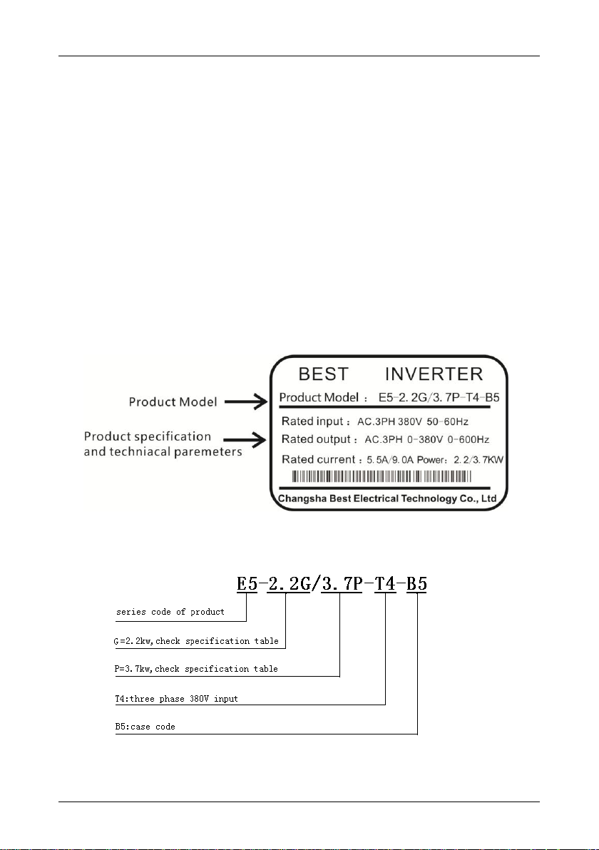
Check the nameplate on the profile of inverter, to confirm the model received is the
right one.
Inverter Nameplate:
Model Explanation:
- 1 -
Page 6

Chapter 1 Summarize E5 User Manual
WARNING indicates the situation in which the failure to follow operating
requirements may result in fire or serious personal injury or even death.
ATTENTION indicates the situation in which the failure to follow operating
requirements may damage to inverter or equipment system.
WARNING
Make sure the power is off before wiring.
Within 10 minutes after turning off AC power supply, there’s high voltage still inside
inverter, which is extremely dangerous. DO NOT touch the electric circuit or any
spare part inside.
When inverter is under working, DO NOT inspect the spare part or signal on electric
circuit.
DO NOT dismount or change the inside wiring, electric circuit or spare part by
yourself.
DO NOT operate inverter with a wet had in case of electric shock.
Ierter ground terminals must be correctly grounded.
It is prohibited to reassemble or change control board and spare parts, otherwise
there will be dangers such as electric shock, explosion, etc.
NEVER open inverter cover or touch the spare parts on circuit board when inverter is
power-on. There is high voltage on these parts. Beware of electric shock which
results death!!!
ATTENTION
DO NOT carry out puncture test on the accessories inside the inverter, for they are prone
to be damaged by high voltage.
NEVER connect the output terminal U.V.W to AC power supply.
When power is on or has been cut off just for a short while, inverter and braking resistor
stay in high temperature, DO NOT touch them in case of being scalded.
The voltage on each terminal must comply with the indication on manual, to prevent
crack and damage.
Inverter main electric board CMOS, IC are prone to be influenced and damaged by static
electricity.
Only qualified specialized persons are permitted to install, debug and maintain the
inverters.
Dump the inverters as industrial waste. Burning is not allowed.
After the inverter being kept aside for long time, inspection and commissioning are
required before using.
Inverters can be set for high speed running easily. Please check whether the motor and
1.1.2 Safety Precautions
Notice: Based on different situations, “CAUTION” issue may also cause severe
consequences. Please comply with above two grade issues, which are both vital to our
individual safety.
- 2 -
Page 7

E5 User Manual Chapter 1 Summarize
mechanic properties are competent before revising the settings.
1.1.3 Other Cautions
Input Power Supply
This series of inverters are not applicable to applications out the range of operating voltage as
set forth in this manual. If necessary, please use booster to rise or drop the voltage to regulated
voltage range.
This series of inverters only apply to AC three-phase 380V input voltage. AC two-phase voltage
input will cause faults even damage to the inverters.
Surge Protection
This series of inverters are furnished with surge suppressor that has certain resistance to
lightning induction. However, users in areas with frequent occurrence of lightning need to
mount an external surge suppressor in front of the inverter power input side.
Operation of Contactor
As to the configuration of peripheral devices recommended by this manual, it is necessary to
mount a contactor between the power supply and this drive input side. Such a contactor should
not be used as a control device for start and stop of the inverter, as frequent charging &
discharging shall reduce the service life of internal electrolytic capacitors.
When it is necessary to mount a contactor between the drive output and the motor, it
should be ensured the drive is in a non-output status before switch-on/switch-off of such a
contactor. Failure to comply may result in inverter damage.
Output Filter
Since the inverter output is PWM high frequency chopping voltage, mounting filter devices such
as an output filter and an output AC reactor between the motor and the inverter shall effectively
reduce output noise, avoiding interference to other surrounding equipments.
If the length of cable between the inverter and the motor exceeds 100m, an output AC reactor
is recommended to use with the purpose of preventing drive fault as a result of overcurrent
caused by excessive distributed capacitance. An output filter is optional depending on field
requirements.
Be sure not to mount phase-shifting capacitor or surge absorber at output side of the inverter
since this may result in inverter damage as a result of over-temperature.
Insulation of the Motor
In view of the fact that the inverter output is PWM high frequency chopping voltage
accompanied by higher harmonics, the noise, temperature rise and vibration of the motor is
higher compared with sinusoidal voltage. Particularly this debases motor insulation. Therefore,
the motor should be subjected to insulation inspection before initial use or reuse after being
stored for a long period of time. The motor in regular service should also be subjected to
regular insulation inspection so as to avoid the inverter damage as a result of motor insulation
- 3 -
Page 8

Chapter 1 Summarize E5 User Manual
ATTENTION
While moving the inverter, please DO NOT directly hold up the front cover, instead, shall
hold the inverter from the pedestal, in case that the front cover slips off or inverter falls
down, even causing damages to human or inverter.
Install the inverter on nonflammable material like metal, to avoid fire disaster.
Choose a proper and safe place to install the inverter, where there is non high
temperature or direct sunlight, to avoid moisture and water drops.
Prevent children or unconcerned people from approaching the inverter.
This inverter can only be used in the areas which are approved by our company,
unapproved performance environment may result in fire disaster, gas explosion,
electrification, etc.
If several inverters are installed in one common control cabinet, please install extra
cooling fans to keep the inside temperature below 40℃, in order to avoid overheat, fire
disaster, etc.
Please at first make sure the power is off then dismount or install the operation keypad,
and fasten the front cover, in case of poor contact which may cause operation fault or non
display.
DO NOT place the inverter in the environment where there is explosive gas, otherwise it
will result in danger of explosion.
In the areas 1000m above sea level, since the heat dissipation of the inverter becomes
worse, please select one grade higher model.
On output side please DO NOT install contactor or other capacitor, varistor related
accessories, otherwise it will cause inverter faults or device damages.
On output side please DO NOT install switching devices such as air switch and contactor.
If these have to be installed at the place due to some technology reason or else, then
please make sure the inverter has NO output action during switch turning on or off. In
addition, it is prohibited to install capacitor with power improving function or
lightning-proof varistor, otherwise, it may result in inverter faults, tripping to protection or
damage to components.
damage. A 500V voltage mode mega-ohmmeter is recommended to use for the measurement
of the motor insulation, during which, it is essential to
disconnect the motor from the inverter. Normally, the insulation resistance of the motor should
be bigger than 5MΩ.
Derating
Due to the thin air in high-altitude areas, the radiating performance of the inverter with forced
air cooling may degrade while the electrolyte of electrolytic capacitors is more volatile, which
can result in reduction in product life. Inverter should be derated when used in an area at the
altitude above 1000 meters. It is recommended to derated 1% for every 100m when the altitude
is above 1000 meters.
- 4 -
Page 9

E5 User Manual Chapter 1 Summarize
Please connect inverter to an independent power supply, definitely NEVER share a
power supply with machines like electric welder, otherwise it may cause inverter to trip for
protection or even damaged.
ATTENTION
Before power on
The power supply voltage adopted must comply with the rated input voltage of the
inverter.
PE symbol means ground terminal. Please make sure to ground the motor and inverter
correctly to ensure safety.
When there is contactors installed between power supply and inverter, please Do Not use
contactor to control the running and stopping of inverter, otherwise it will reduce inverter’s
service life.
Main loop must be wired correctly. R.S.T(L.N) is power supply input terminal, NEVER
connect this terminal with U.V.W, otherwise it will cause inverter damage when power is
on.
During power on
When power is on, NEVER insert or pull the contactors on the inverter, in case that the
surge caused from the inserting or pulling enters into the control mother board and
results in inverter damage.
During Running
When inverter is running, it is prohibited to add or disconnect the motor group, otherwise
it will cause the inverter to over-current trip, or even burn down the main loop of inverter.
DO NOT take off the front cover when power is on, in case it result in human injury or
death.
When fault restart function is turned on, the motor will restart automatically after stop.
Please DO NOT approach the machine to avoid accidents.
Stop switch function is not valid if it is not set before, which is not the same with
emergency stop switch. Please use it carefully.
- 5 -
Page 10
Chapter 1 Summarize E5 User Manual
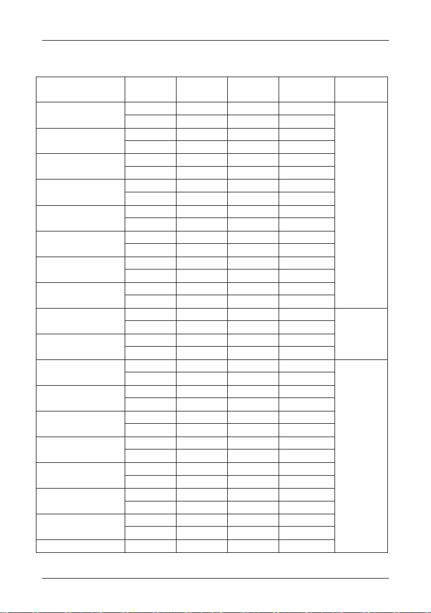
Inverter Model
Power grade
Output
current
Input current
Adapted Motor
Braking unit
E5-0.75G/1.5P-T4-B5
0.75G
2.5
3.4
0.75
built-in
1.5P
3.8
5.1
1.5
E5-1.5G/2.2P-T4-B5
1.5G
3.8
5.1
1.5
2.2P
5.5
9.2
2.2
E5-2.2G/3.7P-T4-B5
2.2G
5.5
9.2
2.2
3.7P 9 14.9
3.7
E5-3.7G/5.5P-T4-B5
3.7G 9 14.9
3.7
5.5P
13
21.5
5.5
E5-5.5G/7.5P-T4-B5
5.5G
13
21.5
5.5
7.5P
17
27.9
7.5
E5-7.5G/11P-T4-B6
7.5G
17
27.9
7.5
11P
24
39
11
E5-11G/15P-T4-B6
11G
24
39
11
15P
30
50.3
15
E5-15G/18.5P-T4-C4
15G
30
50.3
15
18.5P
39
60
18.5
E5-18.5G/22P-T4-C6
18.5G
39
60
18.5
optional
22P
45
69.3
22
E5-22G/30P-T4-C6
22G
45
69.3
22
30P
60
86
30
E5-30G/37P-T4-C7
30G
60
86
30
Externally
Mounted
37P
75
104
37
E5-37G/45P-T4-C7
37G
75
104
37
45P
91
124
45
E5-30G/37P-T4-C8
30G
60
86
30
37P
75
104
37
E5-37G/45P-T4-C8
37G
75
104
37
45P
91
124
45
E5-45G/55P-T4-C9
45G
91
124
45
55P
112
150
55
E5-55G/75P-T4-C9
55G
112
150
55
75P
150
201
75
E5-45G/55P-T4-C10
45G
91
124
45
55P
112
150
55
E5-55G/75P-T4-C10
55G
112
150
55
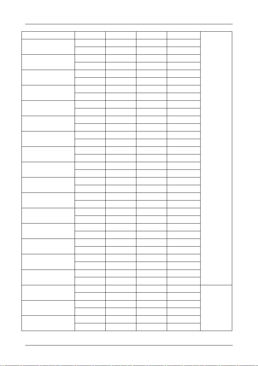
1.2 Pecification Table
- 6 -
Page 11
75P
150
201
75
Externally
Mounted
E5-75G/90P-T4-C11
75G
150
201
75
90P
176
236
90
E5-90G/110P-T4-C11
90G
176
236
90
110P
210
281
110
E5-75G/90P-T4-C12
75G
150
201
75
90P
176
236
90
E5-90G/110P-T4-C12
90G
176
236
90
110P
210
281
110
E5-110G/160P-T4-C13
110G
210
281
110
132P
253
339
132
E5-132G/160P-T4-C13
132G
253
339
132
160P
310
415
160
E5-110G/160P-T4-C14
110G
210
281
110
132P
253
339
132
E5-132G/160P-T4-C14
132G
253
339
132
160P
310
415
160
E5-160G/185P-T4-C15
160G
310
415
160
185P
350
469
180
E5-185G/200P-T4-C15
185G
350
469
180
200P
380
509
200
E5-160G/185P-T4-C16
160G
310
415
160
185P
350
469
180
E5-185G/200P-T4-C16
185G
350
469
180
200P
380
509
200
E5-200G/220P-T4-C18
200G
380
509
200
220P
430
576
220
E5-220G/250P-T4-C18
220G
430
576
220
250P
470
629
250
E5-250G/280P-T4-C20
250G
470
629
250
280P
520
696
280
E5-280G/315P-T4-C20
280G
520
696
280
315P
590
790
315
E5-315G/355P-T4-C22
315G
590
790
315
Externally
mounted
355P
650
871
355
E5-355G/400P-T4-C22
355G
650
871
355
400P
725
971
400
E5-400G/450P-T4-C24
400G
725
971
400
450P
820
1098
450
E5 User Manual Chapter 1 Summarize
- 7 -
Page 12

Chapter 1 Summarize E5 User Manual
E5-450G/500P-T4-C24
450G
820
1098
450
500P
860
1152
500
E5-500G/560P-T4-C26
500G
860
1152
500
560P
950
1273
560
E5-560G/630P-T4-C26
560G
950
1273
560
630P
1100
1474
630
E5-630G-T4-C28
630G
1100
1474
630 - - - -
E5-110G/132P-T4-C14
110G
210
281
110
132P
253
339
132
inverter
Braking unit Braking resistor
voltage
power KW
configuration
configuration
specification
quantity
3 ph 380V
0.75
built-in
externally
mounted
150W /400Ω
1
1.5
built-in
externally
mounted
200W/300Ω
1
2.2
built-in
externally
mounted
250W/200Ω
1
3.7
built-in
externally
mounted
400W/150Ω
1
5.5
built-in
externally
mounted
500W/90Ω
1
7.5
built-in
externally
mounted
800W/60Ω
1
Notes:
1. Maximum adapted motor means the maximum power light load engine for the drive of the
certain inverter model, by the standard of four-pole motor.
2. Rated output current means the output current when output voltage is 380V (or 220V).
3. Overload capacity is represented by the percentage of the overcurrent to the rated current.
When using it repeatedly, please wait till the temperature of inverter and motor decrease
below the temperature under 100% load.
4. Maximum output voltage cannot exceed power supply voltage. Below power supply voltage,
any output voltage can be set freely(voltage peak value of inverter output terminal is DC
voltage).
5. Power supply capacity changes according to the value of impedance (including input reactor
and cable ) on the side of power supply.
1.3 Braking Unit and Braking Resistor
- 8 -
Page 13

E5 User Manual Chapter 1 Summarize
11
built-in
externally
mounted
1000W/47Ω
1
15
built-in
externally
mounted
1500W/47Ω
1
18.5
Built-in optional
externally
mounted
2000W/40Ω
1
22
Built-in optional
externally
mounted
2500W/33Ω
1
30-630
selection as per braking unit requirements and
recommendation
Power input
Rated
voltage
Three phase AC380V±10%
rated
equency
50Hz/60Hz, tolerance ±5%
Power output
output
voltage
Three phase 0~rated input voltage, error within ±3%
output
requency
0.00~600.00Hz, unit: 0.01Hz
overload
apacity
150% 1min;180% 10S;200% 0.5S
Control
Characteristics
control
method
V/F control
V/F separation control
Non-PG vector control 1
Non-PG vector control 2
Speed
control range
1:100 (V/F control)
1:100 (Non-PG vector control 1)
1:200(Non-PG vector control 2)
Speed
control
precision
±0.5% (V/F control)
±0.2% (Non-PG vector control 1)
±0.2% (Non-PG vector control 2)
Starting
torque
0.5Hz:180%(V/F control)
0.5Hz:180%(Non-PG vector control 1)
0.25Hz:180%(Non-PG vector control 2)
Basic Functions
Frequency
setting
digital setting + operation keypad ∧/∨
digital setting + terminal UP/DOWN setting
terminal pulse setting
analog setting (AI1/AI2)
RS485 communication setting
1.4 Technical Characteristics
- 9 -
Page 14

Chapter 1 Summarize E5 User Manual
Starting
method
start under starting frequency
start after DC braking
start in tracking speed
Stopping
method
deceleration stop
free stop
deceleration stop + DC braking
Dynamic
braking
capacity
0.75KW~7.5KW optional built-in braking unit
11KW ~ 15KW standard configuration including built-in
braking unit
18.5KW~22KW optional built-in braking unit
≥30KW, externally mounted braking unit required
input terminal
6 pcs of multi-functional terminals, X6 can be set as high
speed pulse input; 2 analog input
output
terminal
1 analog output;
1 high speed pulse output, 1 normally open normally close
output
simple PLC
control
able to set 0~15 section running speeds & time
Swing
frequency
running
function
applicable to textile industry
others
efficiency
under rated power
7.5kW and below:≥93%
11~45kW:≥95% 55kW and above:≥98%
installation
method
Wall-mounted, cabinet type
IP grade
IP20
cooling
method
forced-air cooling
- 10 -
Page 15
E5 User Manual Chapter 2 Installation and Connection
Chapter 2 Installation and Connection
This chapter indicates basic “installation and connection”, before using please read all the
notices in this chapters carefully.
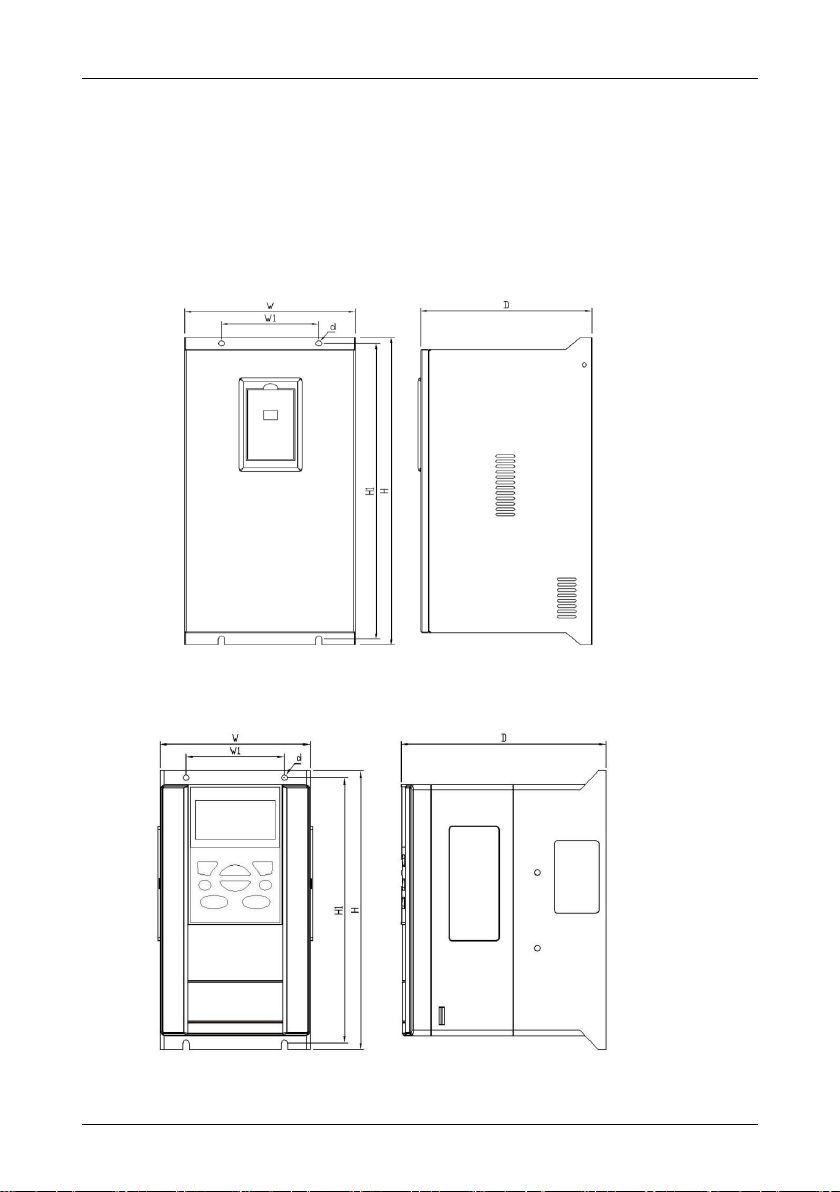
2.1 Case Structure and Dimension
E5 iron Configuration:
E5 plastic Configuration:
- 11 -
Page 16

Chapter 2 Installation and Connection E5 User Manual
Inverter Model
External dimensions
installation dimensions
Mounting
hole dia.
W(mm)
H(mm)
D(mm)
W1(mm)
H1(mm)
d(mm)
B5
107
200
145
70
190
4.5
B6
140
280
192
100
267 6 C4
210
338
194
192
319 7 C6
257
417
203
160
400
8
C8
262
577
262
150
555
10
C9
388
596
252
280
572
10
C10
285
645
258
150
625
10
C11
498
666
278
350
642
10
C12
372
770
310
240
726
12
C13
400
811
303
340
787
12
C14
393
852
302
270
824
12
C15
465
920
325
320
894
10
C16
453
1005
322
320
1005
20
C18
650
970
350
420
970
20
C20
700
1000
355
420
970
26
C22
810
1040
372
560
1010
26
Dimensions of E5 series inverters:
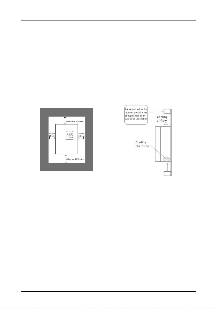
2.2 Installation requirement
Inverter is one kind of precise power electronic products, so the working environment directly
influences the performance and service life of inverter. Therefore, please follow the below:
Check whether the inverter installation position environment comply with 1.2.3 instructions, if
not, please DO NOT install it, otherwise it will cause damage to inverter.
1. Inverter adopts plastic parts, please do not exert a big force on the cover plate. Install
carefully in case of any damage.
2. If conditions allow please openly install the backside plate and cooling fins out of control
cabinet, to effectively decrease the temperature in the electrical control cabinet.
3. Install inverter in clean place if possible, or inside of the enclosed type shield board which
- 12 -
Page 17
E5 User Manual Chapter 2 Installation and Connection
prevents all the floating material.
4. Inverter shall be installed in vertical direction solidly on the installation board with screws.
5. Pay attention to the heat dissipation method of the inverter which is installed in a control
cabinet: under the condition that there are two or more inverters and ventilation fan are
installed together into one electrical control cabinet, please pay attention to select a
proper installation position, for ensuring the temperature surround the inverter is within
the permissible value. If the installation position is not correct, it will cause the
surrounding temperature to rise and the ventilation effect worse.
6. Please install inverter on a nonflammable surface. Inverter temperature may reach a
rather high value (about 80 °C). Meanwhile, in order to facilitate heat dissipation, please
reserve enough space around.
2.3 Connection Guidelines
1. Separate power supply line and control line while installing the wires, e.g. adopt
independent trunking. If control electrical circuit linking must across the cable, they should
be wired in 90°angle.
2. When using shield wire or twisted pair to connect control electric circuit, make sure the
unshielded part as short as possible, if conditions allow, please adopt cable sleeve.
3. Avoid the inverter gravity line(input and output line) and signal line to be parallel-wired or
clustered-wired but should be crossed-wired separately.
4. Please use twisted pair shield wire for connection line of detector and signal line for control.
The sheath of shield wire connects to COM terminal.
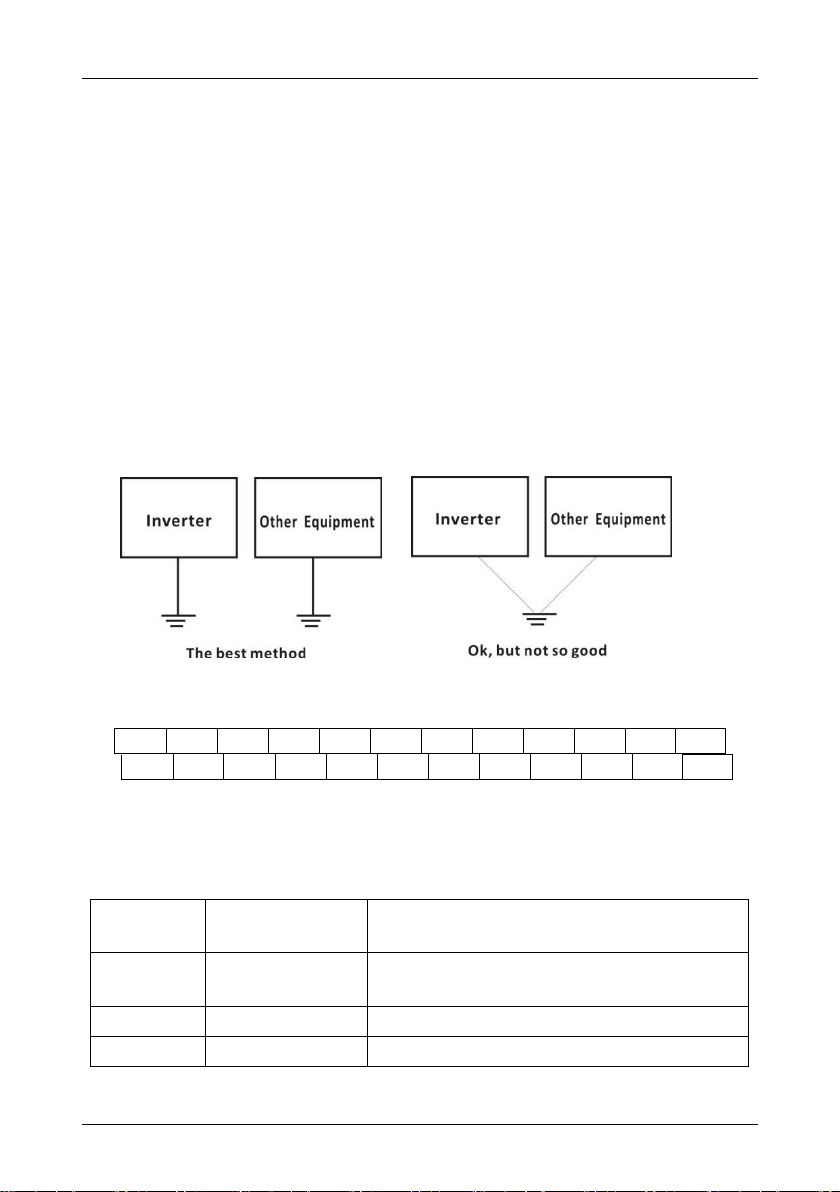
5. The ground wires of inverter and motor shall be connected on a common point.
6. Install data line filter onto signal line.
7. The shield layer of connector line of detector and control signal line must be grounded by
cable metal clamp.
- 13 -
Page 18
Chapter 2 Installation and Connection E5 User Manual
Braking Resistor
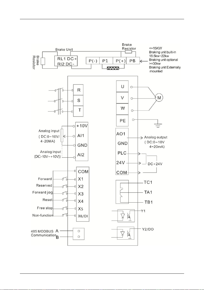
2.4 Connection Instruction
- 14 -
Page 19
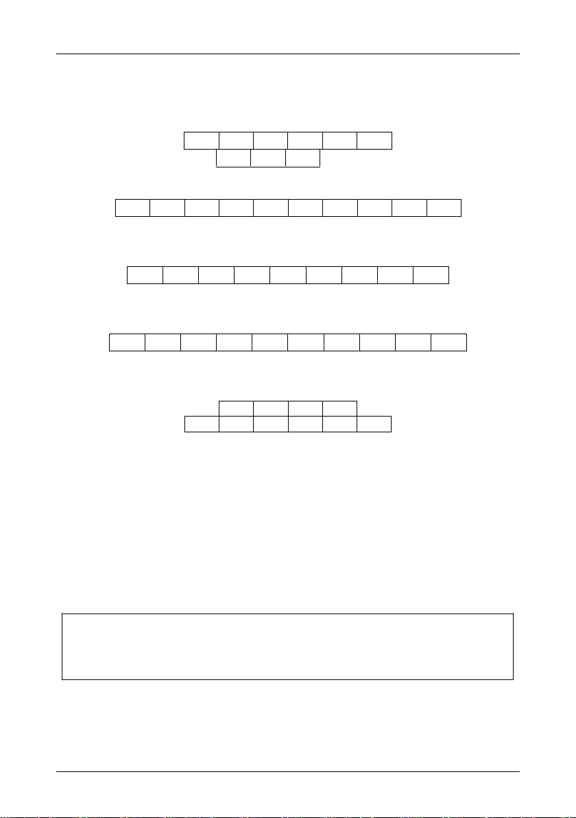
E5 User Manual Chapter 2 Installation and Connection
P+
PB R S T PE
P-
P+ R S T U V W
PB
PE
R S T
PB
P+ U V W PE
P-
P+
PB R S T U V W
PE
PE R S T
P1
P+
P- U V
W
Cable must be of 75°C copper.
Screw with proper strength. Loose screwing will lead to short circuit or wrong
operation, while over-tight screwing will result in damages to screws and terminals, and
short circuit or wrong operation too.
U V W
2.4.1 Inverter Main Loop Terminal Row:
0.75KW-11KW, three-phase 380V:
15KW,three-phase 380V:
18.5KW-22KW, three-phase 380V:
11KW-15KW, three-phase 380V:
30KW-630KW, three-phase 380V:
Notes:
Different models may have some changes, please in kind prevail!
Inverter terminals (P+ , P-) shall be in accordance with braking unit terminal symbol during
wiring, damage will caused if wrongly connected.
The wire distance between braking unit and braking resistor unit shall be kept within 5
meters, or within 10 meters if using twisted pair.
If the transistor in braking unit is damaged (short circuit), resistor will be very hot which is
easy to cause fire. Therefore, installing electromagnetic contactor on inverter input terminal
is recommended because it allows cutting off power when fault occurs.
2.4.2 Main Loop Terminals
- 15 -
Page 20

Chapter 2 Installation and Connection E5 User Manual
Terminal Mark
Terminal Name
Explanation
R, S, T
Three-phase AC input
terminals
Connect to the power frequency supply
380V 50-60Hz
U, V, W
Inverter output
Connect to three phase asynchronous
motor
P+, PB
Connect to braking resistor
Connect braking resistor between P+ and
PB
PE
Grounding
Inverter grounding, must be properly
grounded
Terminal Mark
Terminal Name
Explanation
R, S, T
Three-phase AC input
terminals
Connect to the power frequency supply
380V 50-60Hz
U, V, W
Inverter output
Connect to three phase asynchronous
motor
P+, PB
Resistor connection
terminals
Connect to braking resistor
P+,P-
DC power supply input
terminals
DC input terminals of externally mounted
brake unit
PE
Grounding
Inverter grounding, must be properly
grounded
Terminal Mark
Terminal Name
Explanation
R, S, T
Three-phase AC input
terminals
Connect to the power frequency supply
380V 50-60Hz
U, V, W
Inverter output
Connect to three phase asynchronous
motor
P+, PB
Resistor connection
terminals
Connect to braking resistor
PE
Grounding
Inverter grounding, must be properly
grounded
0.75KW-11KW:
15KW:
18.5KW-22KW:
Above 30KW :
- 16 -
Page 21
E5 User Manual Chapter 2 Installation and Connection
Terminal Mark
Terminal Name
Explanation
R, S, T
Three-phase AC input
terminals
Connect to the power frequency supply
380V 50-60Hz
U, V, W
Inverter output
Connect to three phase asynchronous
motor
P1, P+
DC reactor connection
terminals
Connected with a jumper as factory default
P+,P-
DC power supply input
terminals
DC input terminals of externally mounted
brake unit
PE
Grounding
Inverter grounding, must be properly
grounded
Inverter Capacity
Below 11KW
15-110KW
Above 132KW
Non-ultra-low noise
mode
100m
150m
200m
Ultra-low noise
mode
50m
80m
100m
2.4.3 Main Loop Connection
1. The crimping terminals for power supply or motors must be with insulation tube.
2. Keep in mind that NEVER connect power supply to output terminals of inverter (U, V, W),
otherwise it will damage inverter.
3. After wiring is finished, odd wires must be cleaned up, otherwise they may cause abnormal
performance, failure or fault. When boring on control stand, be aware to prevent the
fragments and powders from entering into inverter.
4. To keep the voltage drop within 2%, please use proper electric wires for wiring. When the
distance between inverter and motor is long, especially under the condition of low frequency,
motor torque will decline due to the decrease of main loop wire voltage.
5. Maximum line distance is 500m, especially for long-distance wiring. Because the parasitic
capacitor generates surge current, which may cause current protection, there will be the
abnormal performance and faults of the devices connected to output terminal. Therefore,
please refer to the maximum wiring distance as below (when inverter connects two or more
motors, wiring distance shall be within 500m):
6. It is recommended to connect optional braking resistor between P+ and B- terminals.
7. Electromagnetic wave interference: there is harmonic wave in inverter input & output
circuits. In high-demanding circumstances please install wireless noise filter on input
terminal, to minimize the interference.
8. On inverter output terminal, DO NOT install power capacitor, surge suppressor or wireless
- 17 -
Page 22
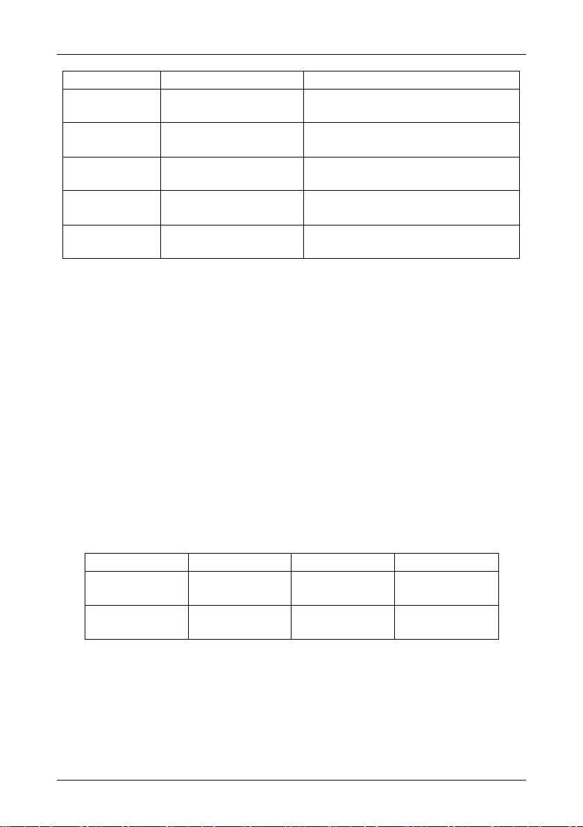
Chapter 2 Installation and Connection E5 User Manual
Terminal
Mark
Terminal Name
Explanation
+10V
Analog input
reference voltage
The resistance of external potentiometer should be
during 4.7KΩ~10KΩ
AI1
Analog input 1
Input 0-10V, PID setting or feedback
AI2
Analog input 2
Input 4-20mA, PID setting or feedback
AI1
AI2
10V
GND
COM
X1
X3
X5
PLC
Y2
24V
TA1 A B
GND
AO1
COM
X2
X4
X6
Y1
COM
TB1
TC1
noise filter, which will lead to inverter fault or component damage.
9. When wiring change is required while power is on or inverter is running, inverter operation
must be stopped then wait for over 10 minutes after power is cut off. Check the voltage by
multi-meter then make the wiring change. There is still dangerous high voltage on capacitor
within a period after power is cut.
10. Ground terminal must be well grounded.
▲Since there is leakage current in inverter, in order to avoid electric shock, inverter and
motor must be grounded.
▲Use independent terminal for inverter grounding. DO NOT just use screw on shell or
chassis instead.
▲ It is recommended to adopt thick cable with demanded diameter no smaller then in the
attached form. Grounding wire should be near inverter, and ground wire be as short as
possible.
▲ When the motor is grounded on inverter side, please use one core of the four-core cable
to ground, with the same size to input wire.
2.4.4 Inverter Control Loop Terminal Row
Notes: Different models may have some changes, please in kind prevail!
2.4.5 Control Loop Terminal Explanation
- 18 -
Page 23

E5 User Manual Chapter 2 Installation and Connection
AO1
Analog output
Switch on control board for jumping from 0~20mA
and 0~10V, factory default: 0~10V
GND
Analog ground
Isolated from COM interiorly
COM
Digital ground
Isolated from GND interiorly
X1
Multi-function
terminal 1
Function defined by value of parameter P20.01,
factory default: “forward”
X2
Multi-function
terminal 2
Function defined by value of parameter P20.02,
factory default : “reverse”
X3
Multi-function
terminal 3
Function defined by value of parameter P20.03,
factory default :“stop”
X4
Multi-function
terminal 4
Function defined by value of parameter P20.04,
factory default: “multi-step speed 1”
X5
Multi-function
terminal 5
Function defined by value of parameter P20.05,
factory default is “multi-step speed 2”
X6(DI)
Multi-function
terminal 6
Function defined by value of parameter P20.06,
factory default is “multi-step speed 3”
A、B
RS485
commumication
Rate: 4800/9600/19200/38400/57600/115200bps
Maximum distance: 500m (use standard network
cable)
Y1
Open collector
output
Range of voltage: 0~24V;Range of current:
0~50mA
Y2(DO)
Open collector
output /Pulse
output
Open collector output: same as Y1;
Pulse output: 0~50kHz
TA1、TB1、
TC1
Relay contactor
output
TA1and TC1 are normally open contactors,TA1
and TB1 are normally closed contactors.
PLC
Digital input
Common terminal
Used for switching between high and low levels,
short-circuited with +24V at delivery, i.e. low value
of digital input valid; External power input
24V
Auxiliary power
supply
24V±10%, Isolated from GND interiorly;
Maximum load: 50mA
2.4.6 Control Loop Connection
1. “COM” is the control signal common terminal , do not public grounded.
2. ”GND” is the Analog signal input/output common terminal, do not public grounded.
- 19 -
Page 24

Chapter 2 Installation and Connection E5 User Manual
3. The wiring of control loop should adopt shielded wire or twisted wire, meanwhile, it must be
wired separately from main loop and strong electricity loop.
4. Because the frequency input signal of control loop is tiny current, please use two
side-by-side contacts or twin contacts to avoid poor contact.
5. It is recommended to use 0.75mm cable for wiring control loop.
6. High voltage CANNOT be input into control loop, otherwise it will damage inverter.
- 20 -
Page 25
E5 User Manual Chapter 2 Installation and Connection
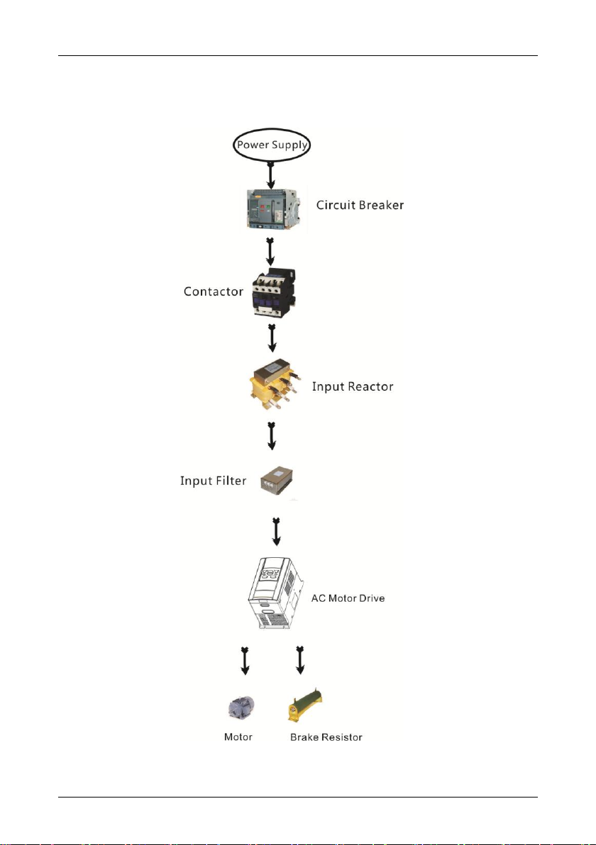
2.4.7 Standard Configuration of Peripheral Devices
- 21 -
Page 26

Chapter 2 Installation and Connection E5 User Manual
Device
Instructions
Power
supply
Input three-phase AC power supply should be in the range as specified in
this manual
Circuit
breaker
Purpose: disconnect power supply and protect the equipments in case of
abnormal over current occurs
Type selection: breaking current of circuit breaker is defined to be 1.5~2
times the rated current of the drive
Breaking time characteristic of circuit breaker should be selected based on
overload protection time characteristic of the drive
RCD
Purpose: since the drive outputs PWM HF chopping voltage, HF leakage
current is inevitable
Type selection: type B dedicated RCD is recommended
Contactor
For safety's sake, do not frequently close and break the contactor since this
may bring about equipment faults
Do not control the start & stop of the drive directly through switch on and off
the contactor since this will result in a reduction on the product life
Input AC
reactor or
DC choke
Improve power factor
Reduce the impact of imbalanced three-phase input AC power supply on
the system
Suppress higher harmonics and reduce the conducted and radiated
interference to peripheral devices
Restrict the impact of impulse current on rectifier bridges
Input filter
Reduce conducted interference from power supply to the drive, improve the
immunity of the drive from noise
Reduce conducted and radiated interference of the drive to peripheral
devices
Brake unit
and
braking
resistor
Purpose: consume motor feedback energy to attain quick brake
Type selection: Contact GTAKE technical personnel for type selection of
brake unit. Refer to type selection of braking resistor in Table 1.3 Type
Selection of Peripheral Devices.
Output filter
Reduce conducted and radiated interference of the drive to peripheral
devices
Output AC
reactor
Avoid the motor insulation damage result from harmonic voltage
Reduce frequent protection from the drive caused by leakage current
In case the cable connecting drive and motor is over 100 meters, output AC
reactor recommended
Motor
Should match the drive
2.4.8 Instructions of Peripheral Devices
- 22 -
Page 27
E5 User Manual Chapter 3 Keypad Operation
Symbol
Key Name
Function
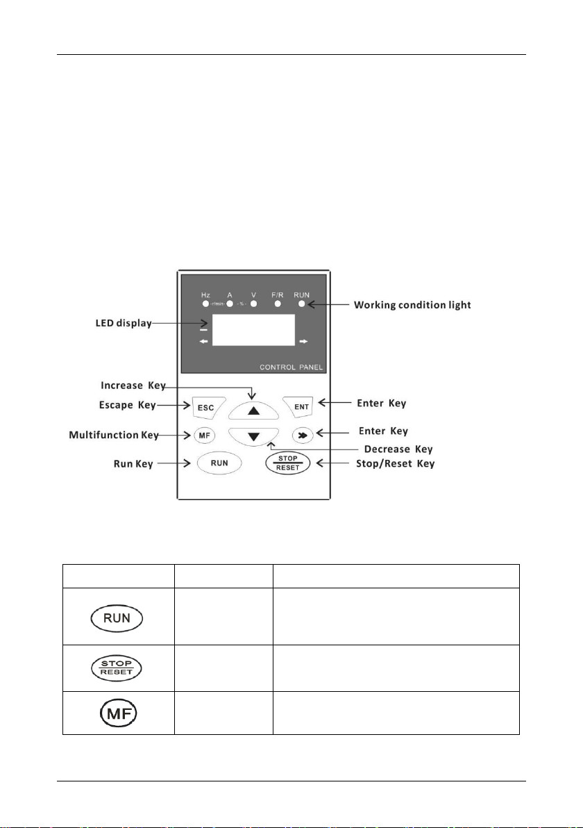
Run key
Inverter starts running once this key is pressed.
This key is invalid when inverter is in external
control mode.
Stop/Reset Key
Inverter stops running when this key is pressed;
Reset inverter by this key under fault alarm.
Multifunction key
Refer to parameter P70.00.
Chapter 3 Keypad Operation
This chapter provides guidance for basic “running operation”, please read it carefully in detail
before using the inverter.
3.1 Operation of Keypad
Operation Keypad is the connector for communication between human and equipment, which
is composed of key part and display part. User inputs control commands through keys, and
display part shows parameter information and different running conditions. Keypad
appearances are as below:
3.2 Operation Keypad Explanation
- 23 -
Page 28
Chapter 3 Keypad Operation E5 User Manual
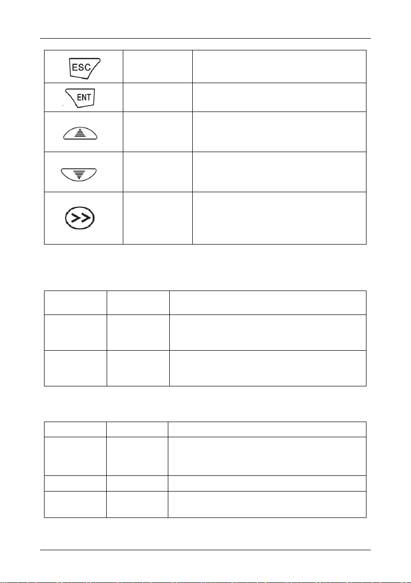
Escape Key
Escape function setting condition.
Enter Key
Function parameter edition enter;
Confirmation/saving of parameter setting.
Increase Key
Increase of selected function code value;
Increase of selected parameter code value;
Increase of set frequency.
Decrease key
Decrease of selected function code value;
Decrease of selected parameter code value;
Decrease of set frequency.
Shift key
Selection of function code value;
Selection of parameter value;
Selection of stop/run status display parameters;
Refer to 3.3 for details.
Condition
Light
Light Name
Explanation
RUN
Running
condition
Indication
ON: Run
OFF: Stop
Flash: Stopping
F/R
Reverse
Indication
ON: Reverse command initiates under stop condition;
Inverter reverses under running condition.
Flash: Shifting from Reverse to Forward.
Condition Light
Name
Explanation
Hz
Frequency
Indication
ON: Present displayed parameter is running frequency
or present function unit is frequency;
Flash: Present displayed parameter is set frequency.
A
Current Display
ON: Present displayed parameter is current.
V
Voltage
Indication
ON: Present displayed parameter is voltage.
3.3 Display Content Explanation
3.3.1 Condition Light Explanation
3.3.2 Unit Light Explanation
- 24 -
Page 29
E5 User Manual Chapter 3 Keypad Operation
Hz+A
Rotating Speed
Indication
ON: Present displayed parameter is rotating speed;
Flash: Present displayed is set rotating speed.
A+V
Percentage
Indication
ON: Present displayed parameter is percentage.
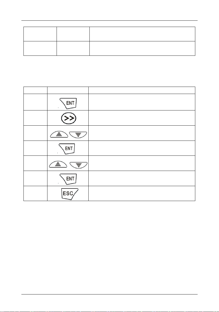
Sequence
Operation
Explanation
1
Enter into parameter menu, e.g. P00-00, inverter
displays present parameter’s first level menu.
2
Adjust to the parameter which requires modification,
e.g. P00-00.
3
Adjust to the required parameter code, e.g. P10-00.
4
Inverter displays the value of present parameter, e.g.
“0”.
5
Adjust to the required value, e.g. “1”.
6
Confirm this operation, save information.
7
Exit parameter setting condition, back to standby or
running condition.
3.4 Parameter Modification Method
If parameters need modification, first you shall enter into the function code which requires
modification, then reset the parameter. Refer to details as below:
Note: When setting parameters, pressing “ESC” key can exit parameter setting state and back
to standby mode.
3.5 Commissioning
3.5.1 Important inspection Before Running
Whether exists wrong wiring, especially check whether the power supply is wrongly
connected to U.V.W terminal;
Please pay attention: power supply should be input from R.S.T(L.N) terminals;
Whether there are metal chips or wires, which may cause short-circuit, left on inverter base
board and wiring terminals;
Whether screws are tightly screwed, whether connectors are loose;
- 25 -
Page 30

Chapter 3 Keypad Operation E5 User Manual
Whether there is short-circuit or short-to-ground on output part.
3.3.2 Commissioning Method
Because the control method of E5 series is set as control panel method before out of factory,
therefore, commissioning can be carried out by operating JOG key on the panel. Normally
commissioning is operated under 5.0Hz.
- 26 -
Page 31

E5 User Manual Chapter 4 List of Parameters
Chapter 4 List of Parameters
ATTENTION:
Change attribute:
"○" means the value of this parameter can be modified in stop and running status of drive;
"●" means the value of this parameter can not be modified when drive is running;
"×" means this parameter is a measured value that cannot be modified;
Factory default value: The value when restored to factory default. Neither measured
parameter value nor recorded value will be restored.
Scope: the scope of setting and display of parameters;
- 27 -
Page 32

Chapter 4 List of Parameters E5 User Manual
Param.
Designation
Scope
Factory
Default
Attr
Group P00: System Parameters
P00.00
Setting of User
Password
0~FFFF
0000
○
P00.01
Display of Parameters
0: Display all parameters
1: Only display parameters P00.00
and P00.01
2: Reserved
A1-00~A1-19
3: Only display P00.00, P00.01,
and the
parameters different with factory
default
0
○
P00.02
Parameter Protection
0: All parameter programmable
1: Only P00.00 and this parameter
programmable
0
●
P00.03
Parameter Initialization
0: No operation
1: Clear fault record
2: Restore all parameters to
factory default (excluding motor
parameters)
3: Restore all parameters to
factory default (including motor
parameters)
4: Restore all parameters to
backup parameters
0
●
P00.04
Parameter Backup
0: No operation
1: Backup all parameters
0
●
P00.06
The inverter model
0:G type (adopted to the constant
torque load)
1: L type (adopted to the fan pump
load)
0
●
P00.07
Reserved
Reserved
Reserved
●
P00.08
Selection of Motor
1/motor 2
0: Motor 1
1: Motor 2
0
●
P00.09
Motor Control Pattern
Unit's place: Control pattern of
motor 1
0: V/f control
1: Sensor-less vector control 1
2: Sensor-less vector control 2
Decade: control pattern of motor 2
0: V/f control
1: Sensor-less vector control 1
Model
defined
●
- 28 -
Page 33

E5 User Manual Chapter 4 List of Parameters
Param.
Designation
Scope
Factory
Default
Attr
2: Sensor-less vector control 2
Group 10: Frequency Command
P10.00
Frequency Command
Pattern
0: Master frequency command
1: Master & auxiliary computation
result
2: Switch between master and
auxiliary command
3: Switch between master
frequency command, and master
& auxiliary computation result
4: Switch between auxiliary
frequency command, and master
& auxiliary computation result
0
●
P10.01
Master Frequency
Command Source
0: Digital setting (P10.02) +
keypad ∧/∨ adjustment
1: Digital setting (P10.02) +
terminal UP/DOWN adjustment
2: Analog input AI1
3: Analog input AI2
4: Reserved
5: X6/DI pulse input
6: Process PID output
7: PLC
8: Multi-step speed
9: Communication
0
●
P10.02
Digital Setting of Master
Frequency
Lower limit frequency ~ Upper limit
frequency
50.00Hz
○
P10.03
Auxiliary Frequency
Command Source
0: No command
1: Digital setting (P10.04) +
Keypad ∧/∨ adjustment
2: Digital setting (P10.04) +
terminal UP/DOWN adjustment
3: Analog input AI1
4: Analog input AI2
5: Reserved
6: X6/DI pulse input
7: Process PID output
8: PLC
9: Multi-step speed
10: Communication
00
●
P10.04
Digital setting of auxiliary
frequency
Lower limit frequency ~ upper limit
frequency
0.00Hz
○
- 29 -
Page 34

Chapter 4 List of Parameters E5 User Manual
Param.
Designation
Scope
Factory
Default
Attr
P10.05
Range of auxiliary
frequency
0: Relative to maximum frequency
1: Relative to master frequency
0
●
P10.06
Coeff of auxiliary
frequency
0.0%~100.0%
100.0%
●
P10.07
Computation of master
and auxiliary frequency
command
0: Master + auxiliary
1: Master - auxiliary
2: Max {master, auxiliary}
3: Min {master, auxiliary}
0
●
P10.08
Maximum frequency
Upper limit frequency ~600.00Hz
50.00Hz
●
P10.09
Upper limit frequency
Lower limit frequency ~ maximum
frequency
50.00Hz
●
P10.10
Lower limit frequency
0.00Hz~upper limit frequency
0.00Hz
●
P10.11
Operation when
command frequency
lower than lower limit
frequency
0: Run at lower limit frequency
1: Run at 0 Hz
2: Stop
0
●
P10.12
Time-delay of stop when
command frequency
lower than lower limit
frequency
0.0s ~ 6553.5s
0.0s
●
P10.13
Lower limit of skip
frequency band 1
0.00Hz~upper limit frequency
0.00Hz
●
P10.14
Upper limit of skip
frequency band 1
0.00Hz~upper limit frequency
0.00Hz
●
P10.15
Lower limit of skip
frequency band 2
0.00Hz~upper limit frequency
0.00Hz
●
P10.16
Upper limit of skip
frequency band 2
0.00Hz~upper limit frequency
0.00Hz
●
P10.17
Lower limit of skip
frequency band 3
0.00Hz~upper limit frequency
0.00Hz
●
P10.18
Upper limit of skip
frequency band 3
0.00Hz~upper limit frequency
0.00Hz
●
P10.19
Jog frequency
0.00Hz~upper limit frequency
5.00Hz
○
Group 11: Start/Stop Control
P11.00
Run command
0: Keypad control
1: Terminal control
2: Communication control
0
●
P11.01
Binding of run command
and frequency command
Unit's place: frequency command
source bundled under keypad
control:
0: No binding
000
●
- 30 -
Page 35

E5 User Manual Chapter 4 List of Parameters
Param.
Designation
Scope
Factory
Default
Attr
1: Digital setting (P10.02) +
keypad ∧/∨ adjustment
2: Digital setting (P10.02) +
terminal UP/DOWN adjustment
3: Analog input AI1
4: Analog input AI2
5: Reserved
6: X6/DI pulse input
7: Process PID output
8: Simple PLC
9: Multi-step frequency
A: Communication input
Decade: frequency command
source bundled under terminal
control (same as unit's place)
Hundreds place: frequency
command source bundled under
communication control (same as
unit's place)
P11.02
Running direction
0: Forward
1: Reverse
0
○
P11.03
Reverse-proof action
0: Reverse enabled
1: Reverse disabled
0
●
P11.04
Dead time between
forward and reverse
0.0s~3600.0s
0.0s
○
P11.05
Start Mode
0: From start frequency
1: DC injection braking at start
2: Flying start
0
●
P11.06
Start frequency
0.00Hz~upper limit frequency
0.00Hz
●
P11.07
Holding time of start
frequency
0.0s~3600.0s
0.0s
○
P11.08
DC braking current at
start
0.0%~100.0%
0.0%
○
P11.09
DC braking time at start
0.00s~30.00s
0.00s
○
P11.10
Flying Start Current
0.0~200.0%
100.0%
●
P11.11
Flying Start Decel Time
0.1s~20.0s
2.0s
●
P11.12
V/f coefficient at flying
start
20.0~100.0%
100.0%
●
P11.13
Stop mode
0: Ramp to stop
1: Coast to stop
2: Ramp to stop + DC brake
0
●
- 31 -
Page 36

Chapter 4 List of Parameters E5 User Manual
Param.
Designation
Scope
Factory
Default
Attr
P11.14
Start frequency of DC
injection braking stop
0.00Hz~upper limit frequency
0.00Hz
●
P11.15
Current of DC injection
braking stop
0.0%~100.0%
0.0%
○
P11.16
Time of DC injection
braking stop
0.00s~30.00s
0.00s
○
P11.17
Overexcitation brake
0: Disabled
1: Enabled
1
●
P11.18
Dynamic brake
0: Disabled
1: Enabled
0
●
P11.19
Dynamic brake threshold
voltage
650V~750V
720V
●
P11.20
Auto restart when power
up again after power
loss
0: Disabled
1: Enabled
0
●
P11.21
Waiting time of auto
restart when power up
again
0.0s~10.0s
0.0s
○
Group P12: Accel/Decel Parameters
P12.00
Accel/Decel time
resolution
0:0.01s
1:0.1s
2:1s
1
●
P12.01
Accel time 1
0s~600.00s/6000.0s/60000s
6.0s
○
P12.02
Decel time 1
0s~600.00s/6000.0s/60000s
6.0s
○
P12.03
Accel time 2
0s~600.00s/6000.0s/60000s
6.0s
○
P12.04
Decel time 2
0s~600.00s/6000.0s/60000s
6.0s
○
P12.05
Accel time 3
0s~600.00s/6000.0s/60000s
6.0s
○
P12.06
Decel time 3
0s~600.00s/6000.0s/60000s
6.0s
○
P12.07
Accel time 4
0s~600.00s/6000.0s/60000s
6.0s
○
P12.08
Decel time 4
0s~600.00s/6000.0s/60000s
6.0s
○
P12.09
Decel time at emergency
stop
0s~600.00s/6000.0s/60000s
6.0s
○
P12.10
Jog Accel time
0s~600.00s/6000.0s/60000s
6.0s
○
P12.11
Jog Decel time
0s~600.00s/6000.0s/60000s
6.0s
○
P12.12
Accel/Decele curve
0: Linear Accel/Decel
1: Broken-line Accel/Decel
2: S-curve Accel/Decel A
3: S-curve Accel/Decel B
4: S-curve Accel/Decel C
0
●
P12.13
Accel time switching
0.00Hz~maximum frequency
0.00Hz
○
- 32 -
Page 37

E5 User Manual Chapter 4 List of Parameters
Param.
Designation
Scope
Factory
Default
Attr
frequency of broken-line
Accel/Decel
P12.14
Decel time switching
frequency of broken-line
Accel/Decel
0.00Hz~maximum frequency
0.00Hz
○
P12.15
Time of initial segment of
Accel S-curve
0.00s~60.00s (S-curve A)
0.20s
○
P12.16
Time of last segment of
Accel S-curve
0.00s~60.00s (S-curve A)
0.20s
○
P12.17
Time of initial segment of
Decel S-curve
0.00s~60.00s (S-curve A)
0.20s
○
P12.18
Time of last segment of
Decel S-curve
0.00s~60.00s (S-curve A)
0.20s
○
P12.19
Proportion of initial
segment of Accel
S-curve
0.0%~100.0% (S-curve B)
20.0%
○
P12.20
Proportion of last
segment of Accel
S-curve
0.0%~100.0% (S-curve B)
20.0%
○
P12.21
Proportion of initial
segment of Decel
S-curve
0.0%~100.0% (S-curve B)
20.0%
○
P12.22
Proportion of last
segment of Decel
S-curve
0.0%~100.0% (S-curve B)
20.0%
○
Group P20 Digital Input
P20.00
Enabled condition of run
command terminals when
power up
0: Trigger edge detected + ON
detected
1: ON detected
0
●
P20.01
Function of terminal X1
0: No function
1: JOG forward
2: JOG reverse
3: Running forward (FWD)
4: Running reverse (REV)
5: Three-wire control
6: Running suspended
7: External stop
8: Emergency stop
9: Stop command + DC brake
10: DC injection braking stop
11: Coast to stop
03
●
P20.02
Function of terminal X2
04
●
P20.03
Function of terminal X3
01
●
P20.04
Function of terminal X4
23
●
P20.05
Function of terminal X5
11
●
P20.06
Function of terminal X6
0
●
P20.07
Reserved
Reserved
●
P20.08
Function of terminal AI1
(Digital enabled)
0
●
P20.09
Function of terminal AI2
(Digital enabled)
0
●
- 33 -
Page 38

Chapter 4 List of Parameters E5 User Manual
Param.
Designation
Scope
Factory
Default
Attr
P20.10
Reserved
12: Terminal UP
13: Terminal DOWN
14: UP/DOWN (including ∧/∨
key) adjustment clear
15: Multi-step frequency terminal 1
16: Multi-step frequency terminal 2
17: Multi-step frequency terminal 3
18: Multi-step frequency terminal 4
19: Accel/Decel time determinant 1
20: Accel/Decel time determinant 2
21: Accel/Decel disabled(ramp
stop not inclusive)
22: External fault input
23: Fault reset (RESET)
24: Pulse input (valid only for
X6/DI)
25: Motor 1/2 switchover
26: Reserved
27: Run command switched to
keypad control
28: Run command switched to
terminal control
29: Run command switched to
communication control
30: Frequency command pattern
shift
31: Master frequency command
switched to digital setting P10.02
32: Auxiliary frequency command
switched to digital setting P10.04
33: PID adjustment direction
34: PID paused
35: PID integration paused
36: PID parameter switch
37: Count input
38: Count clear
39: Length count
40: Length clear
41~62: Reserved
63: Simple PLC paused
64: Simple PLC disabled
65: Clear simple PLC stop memory
0
●
- 34 -
Page 39

E5 User Manual Chapter 4 List of Parameters
Param.
Designation
Scope
Factory
Default
Attr
66: Start wobble frequency
67: Clear wobble frequency status
68: Running prohibited
69: DC injection braking at running
70~99: Reserved
P20.11
Filtering time of digital
input terminal
0.000s~1.000s
0.010s
○
P20.12
Delay time of terminal
X1
0.0s~3600.0s
0.0s
○
P20.13
Delay time of terminal
X2
0.0s~3600.0s
0.0s
○
P20.14
Digital input terminal
enabled status setting 1
Unit's place: X1
0: Positive logic
1: Negative logic
Decade: X2 (same as unit's place)
Hundreds place: X3 (same as
unit's place)
Thousands place: X4 (same as
unit's place)
0000
●
P20.15
Digital input terminal
enabled status setting 2
Unit's place: X5
0: Positive logic
1: Negative logic
Decade: X6 (valid as ordinary
terminal, same as unit's place)
Hundreds place: reserved)
Thousands place: reserved
0000
●
P20.16
Digital input terminal
enabled status setting 3
Unit's place: AI1
0: Positive logic
1: Negative logic
Decade: AI2 (same as unit's place)
Hundreds place: Reserved
Thousands place: reserved
0000
●
P20.17
Terminal UP/DOWN
frequency adjustment
control
Unit's place: action when stop
0: Clear
1: Holding
Decade: action on power loss
0: Clear
1: Holding
Hundreds place: integral function
0: No integral function
1: Integral function enabled
0000
○
- 35 -
Page 40

Chapter 4 List of Parameters E5 User Manual
Param.
Designation
Scope
Factory
Default
Attr
P20.18
Terminal UP/DOWN
frequency change step
size
0.00Hz/s~100.00Hz/s
0.03 Hz/s
○
P20.19
FWD/REV terminal
control mode
0: Two-wire mode 1
1: Two-wire mode 2
2: Three-wire mode 1
3: Three-wire mode 2
0
●
P20.20
Option of virtual input
terminal
000~77F
0: Actual terminal in effect
1: Virtual terminal in effect
Unit's place: BIT0~BIT3: X1~X4
Decade: BIT4~BIT6: X5~X6,
Hundreds place: BIT8~BIT10:
AI1~AI2
000
●
Group P21 Digital Output
P21.00
Y1 output function
0: No output
1: Drive undervoltage
2: Drive running preparation
completed
3: Drive is running
4: Drive in 0Hz running (no output
at stop)
5: Drive in 0Hz running (output at
stop)
6: Running direction
7: Frequency attained
8: Upper limit frequency attained
9: Lower limit frequency attained
10: Frequency higher than FDT 1
11: Frequency higher than FDT 2
12: Reserved
13: Torque being constrained
(speed control mode)
14: Fault output
15: Alarm output
16: Drive (motor) overloaded alarm
17: Drive thermal alarm
18: Zero current detection
19: X1
20:X2
21: Motor 1/ 2 indication
22: Set count value attained
0
○
P21.01
Y2/DO output function
(when used as Y2)
0
○
P21.02
Relay 1 output function
14
○
P21.03
Reserved
15
○
- 36 -
Page 41

E5 User Manual Chapter 4 List of Parameters
Param.
Designation
Scope
Factory
Default
Attr
23: Designated count value
attained
24: Length attained
25: Consecutive running time
attained
26: Accumulative running time
attained
27: Contracting brake control
28: Reserved
29: Positioning approaching
30: PLC step completed
31: PLC cycle completed
32: Wobble frequency attains to
upper or lower limit frequency
33~99: Reserved
P21.04
Y1 output delay time
0.0s~3600.0s
0.0s
○
P21.05
Y2 output delay time
0.0s~3600.0s
0.0s
○
P21.06
Relay 1 output delay
time
0.0s~3600.0s
0.0s
○
P21.07
Reserved
Reserved
Reserved
○
P21.08
Enabled state of digital
output
Unit's place: Y1
0: Positive logic
1: Negative logic
Decade: Y2 (same as unit's place)
Hundreds place: Relay 1 output
(same as unit's place)
Thousands place: Relay 2 output
(same as unit's place)
0000
●
P21.09
Detective object of
frequency doubling
technology(FDT)
Unit's place: FDT1 detective object
0: Set value of speed (frequency
after Accel/Decel)
1: Detected speed value
Decade: FDT2 detective object
0: Set value of speed (frequency
after Accel/Decel)
1: Detected speed value
00
○
P21.10
FDT1 upper bound
0.00Hz~maximum frequency
50.00Hz
○
P21.11
FDT1 lower bound
0.00Hz~maximum frequency
49.00Hz
○
P21.12
FDT2 upper bound
0.00Hz~maximum frequency
25.00Hz
○
P21.13
FDT2 lower bound
0.00Hz~maximum frequency
24.00Hz
○
P21.14
Detection width of
0.00Hz~maximum frequency
2.50Hz
○
- 37 -
Page 42

Chapter 4 List of Parameters E5 User Manual
Param.
Designation
Scope
Factory
Default
Attr
frequency attained
P21.15
Zero current detection
level
0.0%~50.0%
5.0%
○
P21.16
Zero current detection
time
0.01s~50.00s
0.50s
○
Group P22 Analog and Pulse Input
P22.00
Analog input curve
Unit's place: AI1 input curve
0: Curve 1 (2 points)
1: Curve 2 (4 points)
2: Curve 3 (4 points)
Decade: AI2 input curve
(same as unit's place)
Hundreds place: Reserved
Thousands place: reserved
000
●
P22.01
Maximum input of
curve1
Minimum input of curve 1 ~110.0%
100.0%
●
P22.02
Corresponding set value
of maximum input of
curve 1
-100.0%~100.0%
100.0%
●
P22.03
Minimum input of curve
1
-110.0% ~ maximum input of curve
1
0.0%
●
P22.04
Corresponding set value
of minimum input of
curve 1
-100.0%~100.0%
0.0%
●
P22.05
Maximum input of curve
2
Input of inflection point A of curve
2~110.0%
100.0%
●
P22.06
Set value corresponding
to maximum input of
curve 2
-100.0%~100.0%
100.0%
●
P22.07
Input of inflection point A
of curve 2
Input of inflection point B of curve
2 ~ maximum input of curve 2
0.0%
●
P22.08
Set value corresponding
to input of inflection point
A of curve 2
-100.0%~100.0%
0.0%
●
P22.09
Input of inflection point B
of curve 2
Minimum input of curve 2 ~ Input
of inflection point A of curve 2
0.0%
●
P22.10
Set value corresponding
to input of inflection point
B of curve 2
-100.0%~100.0%
0.0%
●
P22.11
Minimum input of curve
2
-110.0%~ input of inflection point B
of curve 2
0.0%
●
- 38 -
Page 43

E5 User Manual Chapter 4 List of Parameters
Param.
Designation
Scope
Factory
Default
Attr
P22.12
Set value corresponding
to minimum input of
curve 2
-100.0%~100.0%
0.0%
●
P22.13
Maximum input of curve
3
Input of inflection point A of curve
3~110.0%
100.0%
●
P22.14
Set value corresponding
to maximum input of
curve 3
-100.0%~100.0%
100.0%
●
P22.15
Input of inflection point A
of curve 3
Input of inflection point B of curve
3~ maximum input of curve 3
0.0%
●
P22.16
Set value corresponding
to Input of inflection point
A of curve 3
-100.0%~100.0%
0.0%
●
P22.17
Input of inflection point B
of curve 3
Minimum input of curve 3~ input of
inflection point A of curve 3
0.0%
●
P22.18
Set value corresponding
to Input of inflection point
B of curve 3
-100.0%~100.0%
0.0%
●
P22.19
Minimum input of curve
3
-110.0%~ input of inflection point B
of curve 3
0.0%
●
P22.20
Set value corresponding to
minimum input of curve 3
-100.0%~100.0%
0.0%
●
P22.21
AI1 terminal filtering time
0.000s~10.000s
0.01s
○
P22.22
AI2 terminal filtering time
0.000s~10.000s
0.01s
○
P22.23
Reserved
Reserved
Reserved
P22.24
DI maximum input
P22.26~50.0kHz
50.0kHz
●
P22.25
Set value corresponding
to DI maximum input
-100.0%~100.0%
100.0%
●
P22.26
DI minimum input
0.0kHz~P22.24
0.0kHz
●
P22.27
Set value corresponding
to DI minimum input
-100.0%~100.0%
0.0%
●
P22.28
DI filtering time
0.000s~1.000s
0.001s
○
Group P23 Analog and Pulse Output
P23.00
AO1 output function
0: No output
1: Command frequency
2: Output frequency
3: Output current
4: Output torque
5: Output voltage
6: Output power
7: Bus voltage
2
○
P23.01
AO2 output function
1
○
P23.02
Y2/DO output function
(when used as DO)
2
○
- 39 -
Page 44

Chapter 4 List of Parameters E5 User Manual
Param.
Designation
Scope
Factory
Default
Attr
8: Reserved
9: Torque current
10: Magnetic flux current
11:AI1
12:AI2
13: Reserved
14: Reserved
15:DI
16:Communication input
percentage
17: Output frequency before
compensation
18~99: Reserved
P23.03
AO1 offset
-100.0%~100.0%
0.0%
●
P23.04
AO1 gain
-2.000~2.000
1.000
●
P23.05
AO1 filtering time
0.0s~10.0s
0.0s
○
P23.06
Reserved
Reserved
Reserved
P23.07
Reserved
Reserved
Reserved
P23.08
Reserved
Reserved
Reserved
P23.09
DO maximum output
pulse frequency
0.1kHz~50.0kHz
50.0kHz
○
P23.10
DO output center point
0: No center point
1: Center point is (P23.09)/2, and
the corresponding parameter value
is positive when frequency is higher
than center point
2: Center point is (P23.09)/2, and
the corresponding parameter
value is positive when frequency is
lower than center point
0
●
P23.11
DO output filtering time
0.00s~10.00s
0.01s
○
Group P24 Automatic Correction of Analog Input
P24.00
Analog corrected
channel
0: No correction
1:Correct AI1
2:Correct AI2
3: Reserved
0
●
P24.01
Sampling value of
calibration point 1 of AI1
0.00V~10.00V
1.00V
×
P24.02
Input value of calibration
point 1 of AI1
0.00V~10.00V
1.00V
●
- 40 -
Page 45

E5 User Manual Chapter 4 List of Parameters
Param.
Designation
Scope
Factory
Default
Attr
P24.03
Sampling value of
calibration point 2 of AI1
0.00V~10.00V
9.00V
×
P24.04
Input value of calibration
point 2 of AI1
0.00V~10.00V
9.00V
●
P24.05
Sampling value of
calibration point 1 of AI2
0.00V~10.00V
1.00V
×
P24.06
Input value of calibration
point 1 of AI2
0.00V~10.00V
1.00V
●
P24.07
Sampling value of
calibration point 2 of AI2
0.00V~10.00V
9.00V
×
P24.08
Input value of calibration
point 2 of AI2
0.00V~10.00V
9.00V
●
P24.09
Reserved
Reserved
Reserved
P24.10
Reserved
Reserved
Reserved
P24.11
Reserved
Reserved
Reserved
P24.12
Reserved
Reserved
Reserved
Group P30 Parameters of Motor 1
P30.00
Type of motor 1
0: Ordinary asynchronous motor
1: Variable frequency
asynchronous motor
0
●
P30.01
Power rating of motor 1
0.4kW~6553.5kW
Model
defined
●
P30.02
Rated voltage of motor 1
0V~480V
380V
●
P30.03
Rated current of motor 1
0.0A~6553.5A
Model
defined
●
P30.04
Rated frequency of
motor 1
0.00Hz~600.00Hz
50.00Hz
●
P30.05
Pole pairs of motor 1
1~80
4
●
P30.06
Rated speed of motor 1
0~65535r/min
Model
defined
●
P30.07
Stator resistance R1 of
async motor 1
0.001Ω~65.535Ω
Model
defined
●
P30.08
Leakage inductance L1
of async motor 1
0.1mH~6553.5mH
Model
defined
●
P30.09
Rotor resistance R2 of
async motor 1
0.001Ω~65.535Ω
Model
defined
●
P30.10
Mutual inductance L2 of
asynchronous motor 1
0.1mH~6553.5mH
Model
defined
●
- 41 -
Page 46

Chapter 4 List of Parameters E5 User Manual
Param.
Designation
Scope
Factory
Default
Attr
P30.11
No-load current of async
motor 1
0.0A~6553.5A
Model
defined
●
P30.12
Field weakening coeff 1
of async motor 1
0.0000~1.0000
Model
defined
●
P30.13
Field weakening coeff 2
of async motor 1
0.0000~1.0000
Model
defined
●
P30.14
Field weakening coeff 3
of async motor 1
0.0000~1.0000
Model
defined
●
P30.15
Reserved
Reserved
Reserved
P30.16
Reserved
Reserved
Reserved
P30.17
Reserved
Reserved
Reserved
P30.18
Reserved
Reserved
Reserved
P30.19
Reserved
Reserved
Reserved
P30.20
Reserved
Reserved
Reserved
P30.21
Reserved
Reserved
Reserved
P30.22
Autotuning of motor 1
0: No autotuning
1: Static autotuning of async motor
2: Rotary autotuning of async
motor
0
●
P30.23
Overload protection
mode of motor 1
0: No protection
1: Judged from motor current
2: Judged from temperature
transducer
1
●
P30.24
Overload protection
detection time of motor 1
0.1min~15.0min
5.0min
●
P30.25
Input source of
temperature transducer
signal of motor 1
0: AI1
1: AI2
2: Reserved
1
●
P30.26
Thermal protection
threshold of temperature
transducer of motor 1
0.00V~10.00V
10.00V
●
Group P31 V/f Control Parameters of Motor 1
P31.00
V/f curve setting
0: Linear V/f
1: Multi-stage V/f (P31.01~P31.08)
2: 1.2nd power
3: 1.4th power
4: 1.6th power
5: 1.8th power
6: 2.0nd power
7: V/f separated mode 1
8: V/f separated mode 2
0
●
- 42 -
Page 47

E5 User Manual Chapter 4 List of Parameters
Param.
Designation
Scope
Factory
Default
Attr
P31.01
V/f frequency value f3
0.00Hz~rated frequency of motor
50.00Hz
●
P31.02
V/f voltage value V3
0.0%~100.0%
100.0%
●
P31.03
V/f frequency value f2
P31.05~P31.01
0.00Hz
●
P31.04
V/f voltage value V2
0.0%~100.0%
0.0%
●
P31.05
V/f frequency value f1
P31.07~P31.03
0.00Hz
●
P31.06
V/f voltage value V1
0.0%~100.0%
0.0%
●
P31.07
V/f frequency value f0
0.00Hz~P31.05
0.00Hz
●
P31.08
V/f voltage value V0
0.0%~100.0%
0.0%
●
P31.09
Torque boost
0.0%~30.0%
0.0%
○
P31.10
Slip compensation gain
0.0%~400.0%
100.0%
○
P31.11
Droop control
0.00Hz~mximum frequency
0.00Hz
○
P31.12
Current limitation mode
0: Disabled
1: Set by P31.13
2: Set by AI1
3: Set by AI2
4: Reserved
5: Set by X6/DI
1
●
P31.13
Digital setting of current
limit value
20.0%~200.0%
160.0%
●
P31.14
Current limit coeff on
field weakening
0.001~1.000
0.500
○
P31.15
Energy saving
percentage
0%~40.0%
0.0%
○
P31.16
V/f oscillation
suppression gain 1
0~3000
16
○
P31.17
V/f oscillation
suppression gain 2
0~3000
20
○
P31.18
Voltage setting in V/f
separated pattern
0: P31.19 digital setting
1: Set by AI1
2: Set by AI2
3: Reserved
4: Process PID output
5: AI1 + process PID output
0
●
P31.19
Voltage digital setting in
V/f separated pattern
0.0%~100.0%
0.0%
○
P31.20
Voltage variation time in
V/f separated pattern
0.00s~600.00s
0.01s
○
Group P32 Vector Control Parameters of Motor 1
P32.00
Speed/torque control
0: speed control
1: torque control
0
●
- 43 -
Page 48

Chapter 4 List of Parameters E5 User Manual
Param.
Designation
Scope
Factory
Default
Attr
P32.01
ASR high-speed
proportional gain Kp1
0.0~20.0
2.0
○
P32.02
ASR high-speed
integration time Ti1
0.000s~8.000s
0.200
○
P32.03
ASR low-speed
proportional gain Kp2
0.0~20.0
2.0
○
P32.04
ASR low-speed
integration time Ti2
0.000s~8.000s
0.200
○
P32.05
ASR switching
frequency 1
0.00Hz~P32.06
5.00Hz
○
P32.06
ASR switching
frequency 2
P32.05~upper limit frequency
10.00Hz
○
P32.07
ASR input filtering time
0.0ms~500.0ms
0.3ms
○
P32.08
ASR output filtering time
0.0ms~500.0ms
0.3ms
○
P32.09
ACR proportion
coefficient Kp
0.000~4.000
1.000
○
P32.10
ACR integration
coefficient Ki
0.000~4.000
1.000
○
P32.11
Pre-excitation time
0.000s~5.000s
0.200s
○
P32.12
Driven torque limited
source
0: P32.14 digital setting
1: Analog input AI1
2: Analog input AI2
3: RESERVED
4: X6/DI pulse input
5: Communication
0
●
P32.13
Brake torque limited
source
0: P32.15 digital setting
1: Analog input AI1
2: Analog input AI2
3: Reserved
4: X6/DI pulse input
5: Communication
0
●
P32.14
Digital setting of driven
torque
0.0%~200.0%
180.0%
○
P32.15
Digital setting of brake
torque
0.0%~200.0%
180.0%
○
P32.16
Torque limit coefficient in
field weakening
0.0%~100.0%
50.0%
○
P32.17
Driven slip
compensation gain
10.0%~300.0%
100.0%
○
- 44 -
Page 49

E5 User Manual Chapter 4 List of Parameters
Param.
Designation
Scope
Factory
Default
Attr
P32.18
Brake slip compensation
gain
10.0%~300.0%
100.0%
○
Group P33 Parameters of Motor 2
P33.00
Type of motor 2
0: Ordinary asynchronous motor
1: Variable frequency
asynchronous motor
0
●
P33.01
Power rating of motor 2
0.4kW~6553.5kW
Model
defined
●
P33.02
Rated voltage of motor 2
0V~480V
380V
●
P33.03
Rated current of motor 2
0.0A~6553.5A
Model
defined
●
P33.04
Rated frequency of
motor 2
0.00Hz~600.00Hz
50.00Hz
●
P33.05
Pole pairs of motor 2
1~80
4
●
P33.06
Rated speed of motor 2
0~65535r/min
Model
defined
●
P33.07
Stator resistance R1 of
async motor 2
0.001Ω~65.535Ω
Model
defined
●
P33.08
Leakage inductance L1
of async motor 2
0.1mH~6553.5mH
Model
defined
●
P33.09
Rotor resistance R2 of
async motor 2
0.001Ω~65.535Ω
Model
defined
●
P33.10
Mutual inductance L2 of
asynchronous motor 2
0.1mH~6553.5mH
Model
defined
●
P33.11
No-load current of async
motor 2
0.0A~6553.5A
Model
defined
●
P33.12
Field weakening coeff 1
of async motor 2
0.0000~1.0000
Model
defined
●
P33.13
Field weakening coeff 2
of async motor 2
0.0000~1.0000
Model
defined
●
P33.14
Field weakening coeff 3
of async motor 2
0.0000~1.0000
Model
defined
●
P33.15
Reserved
Reserved
Reserved
P33.16
Reserved
Reserved
Reserved
P33.17
Reserved
Reserved
Reserved
P33.18
Reserved
Reserved
Reserved
P33.19
Reserved
Reserved
Reserved
P33.20
Reserved
Reserved
Reserved
- 45 -
Page 50

Chapter 4 List of Parameters E5 User Manual
Param.
Designation
Scope
Factory
Default
Attr
P33.21
Reserved
Reserved
Reserved
P33.22
Autotuning of motor 2
0: No identification
1: Static identification of async
motor
2: Rotating identification of async
motor
0
●
P33.23
Overload protection
mode of motor 2
0: No protection
1: Judged from motor current
2: Judged from temperature
transducer
1
●
P33.24
Overload protection
detection time of motor 2
0.1min~15.0min
5.0min
●
P33.25
Input source of
temperature transducer
signal of motor 2
0: AI1
1: AI2
2: Reserved
0
●
P33.26
Thermal protection
threshold of temperature
transducer of motor 2
0.00V~10.00V
10.00V
●
Group P34 V/f Control Parameters of Motor 2
P34.00
V/f curve setting
0: Linear V/f
1: Multi-stage V/f (P31.01~P31.08)
2: 1.2nd power
3: 1.4th power
4: 1.6th power
5: 1.8th power
6: 2.0nd power
7: V/f separated mode 1
8: V/f separated mode 2
0
●
P34.01
V/f frequency value f3
0.00Hz~rated frequency of motor
50.00Hz
●
P34.02
V/f voltage value V3
0.0%~100.0%
100.0%
●
P34.03
V/f frequency value f2
P34.05~ P34.01
0.00Hz
●
P34.04
V/f voltage value V2
0.0%~100.0%
0.0%
●
P34.05
V/f frequency value f1
P34.07~ P34.03
0.00Hz
●
P34.06
V/f voltage value V1
0.0%~100.0%
0.0%
●
P34.07
V/f frequency value f0
0.00Hz~ P34.05
0.00Hz
●
P34.08
V/f voltage value V0
0.0%~100.0%
0.0%
●
P34.09
Torque boost
0.0%~30.0%
0.0%
○
P34.10
Slip compensation gain
0.0%~400.0%
100.0%
○
P34.11
Droop control
0.00Hz~mximum frequency
0.00Hz
○
P34.12
Current limitation mode
0: Disabled
1: Set by P34.13
1
●
- 46 -
Page 51

E5 User Manual Chapter 4 List of Parameters
Param.
Designation
Scope
Factory
Default
Attr
2: Set by AI1
3: Set by AI2
4: Reserved
5: Set by X6/DI
P34.13
Digital setting of current
limit value
20.0%~200.0%
160.0%
●
P34.14
Current limit coeff on
field weakening
0.001~1.000
0.500
○
P34.15
Energy saving
percentage
0%~40.0%
0.0%
○
P34.16
V/f oscillation
suppression gain 1
0~3000
16
○
P34.17
V/f oscillation
suppression gain 2
0~3000
20
○
P34.18
Voltage setting in V/f
separated pattern
0: P34.19 digital setting
1: Set by AI1
2: Set by AI2
3: Reserved
4: Process PID output
5: AI1 + process PID output
0
○
P34.19
Voltage digital setting in
V/f separated pattern
0.0%~100.0%
0.0%
○
P34.20
Voltage variation time in
V/f separated pattern
0.00s~600.00s
0.01s
○
Group P35 Vector Control Parameters of Motor 2
P35.00
Speed/torque control
0: speed control
1: torque control
Reserve
●
P35.01
ASR high-speed
proportional gain Kp1
0.0~20.0
2.0
○
P35.02
ASR high-speed
integration time Ti1
0.000s~8.000s
0.200
○
P35.03
ASR low-speed
proportional gain Kp2
0.0~20.0
2.0
○
P35.04
ASR low-speed
integration time Ti2
0.000s~8.000s
0.200
○
P35.05
ASR switching
frequency 1
0.00Hz~P32.06
5.00Hz
○
P35.06
ASR switching
frequency 2
P32.05~upper limit frequency
10.00Hz
○
P35.07
ASR input filtering time
0.0ms~500.0ms
0.3ms
○
- 47 -
Page 52

Chapter 4 List of Parameters E5 User Manual
Param.
Designation
Scope
Factory
Default
Attr
P35.08
ASR output filtering time
0.0ms~500.0ms
0.3ms
○
P35.09
ACR proportion coeff Kp
0.000~4.000
1.000
○
P35.10
ACR integration coeff Ki
0.000~4.000
1.000
○
P35.11
Pre-excitation time
0.000s~5.000s
0.200s
○
P35.12
Electric-driven torque
limitation source
0: P35.14 digital setting
1: Analog input AI1
2: Analog input AI2
3: Reserved
4: X6/DI pulse input
5: Communication
0
●
P35.13
Limitation mode of
braking torque
0: P35.15 digital setting
1: Analog input AI1
2: Analog input AI2
3: Reserved
4: X6/DI pulse input
5: Communication
0
●
P35.14
Digital setting of
electric-driven torque
0.0%~200.0%
180.0%
○
P35.15
Digital setting of brake
torque
0.0%~200.0%
180.0%
○
P35.16
Torque limit coefficient in
flux weakening
0.0%~100.0%
50.0%
○
P35.17
Electric-driven slip
compensation gain
10.0%~300.0%
100.0%
○
P35.18
Brake slip compensation
gain
10.0%~300.0%
100.0%
○
Group P40 Enhanced function
P40.00
Carrier frequency
≤15kW:
0.7kHz~16.0kHz, factory default:
8.0 kHz
18.5kW~45kW:
0.7kHz~10.0kHz, factory default:
4.0 kHz
55kW~75kW:
0.7kHz~16.0kHz, factory default:
3.0 kHz
≥90kW:
0.7kHz~3.0kHz, factory default:
2.0 kHz
Model
defined
○
P40.01
Reserved
Reserved
Reserved
- 48 -
Page 53

E5 User Manual Chapter 4 List of Parameters
Param.
Designation
Scope
Factory
Default
Attr
P40.02
Command when running
time attained
Unit's place: command when
consecutive running time attained:
0: Continue to run
1: Stop and fault alarm
Decade: command when
accumulative running time
attained:
0: Continue to run
1: Stop and fault alarm
Hundreds place: unit of running
time
0: Second
1: Hour
000
●
P40.03
Consecutive running
time
0.0s(h)~6000.0s(h)
0.0 s (h)
●
P40.04
Accumulative running
time setting
0.0s(h)~6000.0s(h)
0.0 s (h)
●
P40.05
Contracting brake
control
0: Disabled
1: Enabled
0
●
P40.06
Contracting brake
release frequency
0.00Hz~10.00Hz
2.50Hz
●
P40.07
Contracting brake
release current
0.0%~200.0%
120.0%
●
P40.08
Accel delay time after
contracting brake
release
0.0s~10.0s
1.0s
●
P40.09
Contracting brake
frequency
0.00Hz~10.00Hz
2.00Hz
●
P40.10
Contracting brake
suction waiting time
0.0s~10.0s
0.0s
●
P40.11
Contracting brake
suction holding time
0.0s~10.0s
1.0s
●
Group P41 Protection Parameters
P41.00
Overvoltage stall
O: Prohibited
1: Allowed
1
●
P41.01
Overvoltage stall
protection voltage
120%~150%
135%
●
P41.02
Undervoltage stall
0: Disabled
1: Enabled
0
●
P41.03
Overload alarm
Unit's place: detection option:
0: Always detect
000
●
- 49 -
Page 54

Chapter 4 List of Parameters E5 User Manual
Param.
Designation
Scope
Factory
Default
Attr
1: Detect at constant speed only
Decade: compared object:
0: Rated current of motor
1: Rated current of drive
Hundreds place: alarm option
0: Fault reported and continue to
run
1: Fault reported and coast to stop
P41.04
Overload alarm
threshold
20.0%~200.0%
130.0%
○
P41.05
Overload alarm
activated time that
exceeding threshold
0.1s~60.0s
5.0s
○
P41.06
Protection action 1
Unit's place: encoder
disconnection action:
0: Fault reported and coast to stop
1: Fault reported but continue to
run
Decade: temperature sampling
disconnection action:
0: Fault reported and coast stop
1: Fault reported and continue to
run
Hundreds place: abnormal
EEPROM :
0: Fault reported and coast stop
1: Fault reported and continue to
run
Thousands place: abnormal
terminal communication:
0: Fault reported and coast stop
1: Fault reported and continue to
run
0000
●
P41.07
Protection action 2
Unit's place: abnormal keypad
communication:
0: Fault reported and coast stop
1: Fault reported and continue to
run
Decade: current detection circuit
failed
0: Fault reported and coast stop
1: Fault reported and continue to
0000
●
- 50 -
Page 55

E5 User Manual Chapter 4 List of Parameters
Param.
Designation
Scope
Factory
Default
Attr
run
Hundreds place: abnormal
contactor:
0: Fault reported and coast stop
1: Fault reported and continue to
run
Thousands place: input/output
phase loss:
0: Input phase loss protection
disabled, output phase loss
protection disabled
1: Input phase loss protection
disabled, output phase loss
protection enabled
2: Input phase loss protection
enabled, output phase loss
protection disabled
3: Input phase loss protection
enabled, output phase loss
protection enabled
P41.08
Fault memory after
power loss
0: Not memorized after power loss
1: Memorized after power loss
0
●
P41.09
Times of automatic reset
0~20
0
●
P41.10
Interval of automatic
reset
2.0s~20.0s
2.0s
●
P41.11
Relay action at drive
fault
Unit's place: when undervoltage
fault occurs
0: No action
1: Action enabled
Decade: when fault locked
0: No action
1: Action enabled
Hundreds place: interval of
automatic reset
0: No action
1: Action enabled
010
●
P41.12
Cooling fan control
0: Auto run
1: Always run
0
○
P41.13
Drive thermal alarm
threshold
0.0℃~100.0℃
80.0℃
○
Group P50 Process PID
- 51 -
Page 56

Chapter 4 List of Parameters E5 User Manual
Param.
Designation
Scope
Factory
Default
Attr
P50.00
PID setting
0: P50.01 digital setting
1: AI1
2: AI2
3: Reserved
4: X6/DI pulse input
5: Communication
0
●
P50.01
PID digital setting
0.0%~100.0%
50.0%
○
P50.02
PID feedback
0: AI1
1: AI2
2: Reserved
3: AI1+AI2
4: AI1-AI2
5: Max {AI1, AI2}
6: Min {AI1, AI2}
7: X6/DI pulse input
8: Communication
0
●
P50.03
PID adjustment
Unit's place: output frequency
0: Must be the same direction as
setting running direction
1: Opposite direction allowed
Decade: integration selection
0: Integral continued when
frequency attains upper/lower
frequency
1: Integral stopped when
frequency attains upper/lower limit
11
●
P50.04
PID positive and
negative adjustment
0: Positive adjustment
1: Negative adjustment
0
●
P50.05
Filtering time of PID
setting
0.00s~60.00s
0.00s
○
P50.06
Filtering time of PID
feedback
0.00s~60.00s
0.00s
○
P50.07
Filtering time of PID
output
0.00s~60.00s
0.00s
○
P50.08
Proportional gain Kp1
0.0~100.0
2.0
○
P50.09
Integration time Ti1
0.0s~100.0s
1.0s
○
P50.10
Differential time Td1
0.0s~100.0s
0.0s
○
P50.11
Proportional gain Kp2
0.0~100.0
2.0
○
P50.12
Integration time Ti2
0.0s~100.0s
1.0s
○
P50.13
Differential time TP32
0.0s~100.0s
0.0s
○
P50.14
PID parameter switch
0: No switch, determined by
0
●
- 52 -
Page 57

E5 User Manual Chapter 4 List of Parameters
Param.
Designation
Scope
Factory
Default
Attr
parameters Kp1, Ti1 and Td1
1: Auto switch on the basis of input
offset
2: Switched by terminal
P50.15
Input offset under PID
auto switch
0.0%~100.0%
20.0%
○
P50.16
Sampling period T
0.001s~50.000s
0.002s
○
P50.17
PID offset limit
0.0%~100.0%
0.0%
○
P50.18
PID differential limit
0.0%~100.0%
0.5%
○
P50.19
PID initial value
0.0%~100.0%
0.0%
●
P50.20
Holding time of PID
initial value
0.0s~3600.0s
0.0s
○
P50.21
PID feedback loss
detection value
0.0%~100.0%
0.0%
○
P50.22
PID feedback loss
detection time
0.0s~30.0s
1.0s
○
P50.23
Maximum frequency if it is
opposite to command
running direction
0.00Hz~mximum frequency
50.00Hz
○
P50.24
PID computation option
0: No computation in stop status
1: Computation continued in stop
status
0
○
Group P51 Multi-step Frequency
P51.00
Frequency command
source of multi-step 0
0: Digital setting P51.02
1: Digital setting P10.02 + keypad
∧/∨ adjustment
2: Digital setting P10.02 + terminal
UP/DOWN adjustment
3: AI1
4: AI2
5: Reserved
6: X6/DI pulse input
7: Process PID output
8: Communication
0
●
P51.01
Frequency command
source of multi-step 1
0: Digital setting P51.03
1: Digital setting P10.04 + keypad
∧/∨ adjustment
2: Digital setting P10.04 + terminal
UP/DOWN
3: AI1
4: AI2
0
●
- 53 -
Page 58

Chapter 4 List of Parameters E5 User Manual
Param.
Designation
Scope
Factory
Default
Attr
5: Reserved
6: X6/DI pulse input
7: Process PID output
8: Communication
P51.02
Multi-step frequency 0
Lower limit frequency ~ upper limit
frequency
0.00Hz
○
P51.03
Multi-step frequency 1
Lower limit frequency ~ upper limit
frequency
0.00 Hz
○
P51.04
Multi-step frequency 2
Lower limit frequency ~ upper limit
frequency
0.00 Hz
○
P51.05
Multi-step frequency 3
Lower limit frequency ~ upper limit
frequency
0.00 Hz
○
P51.06
Multi-step frequency 4
Lower limit frequency ~ upper limit
frequency
0.00 Hz
○
P51.07
Multi-step frequency 5
Lower limit frequency ~ upper limit
frequency
0.00 Hz
○
P51.08
Multi-step frequency 6
Lower limit frequency ~ upper limit
frequency
0.00 Hz
○
P51.09
Multi-step frequency 7
Lower limit frequency ~ upper limit
frequency
0.00 Hz
○
P51.10
Multi-step frequency 8
Lower limit frequency ~ upper limit
frequency
0.00 Hz
○
P51.11
Multi-step frequency 9
Lower limit frequency ~ upper limit
frequency
0.00 Hz
○
P51.12
Multi-step frequency 10
Lower limit frequency ~ upper limit
frequency
0.00 Hz
○
P51.13
Multi-step frequency 11
Lower limit frequency ~ upper limit
frequency
0.00 Hz
○
P51.14
Multi-step frequency 12
Lower limit frequency ~ upper limit
frequency
0.00 Hz
○
P51.15
Multi-step frequency 13
Lower limit frequency ~ upper limit
frequency
0.00 Hz
○
P51.16
Multi-step frequency 14
Lower limit frequency ~ upper limit
frequency
0.00 Hz
○
P51.17
Multi-step frequency 15
Lower limit frequency ~ upper limit
frequency
0.00 Hz
○
Group P52 Simple PLC (based on multi-step frequency)
P52.00
Running mode of simple
PLC
Unit's place: PLC running mode
0: Stop after a single cycle
1: Continue to run with the last
frequency after a single cycle
0000
●
- 54 -
Page 59

E5 User Manual Chapter 4 List of Parameters
Param.
Designation
Scope
Factory
Default
Attr
2: Repeat cycles
Decade: power loss memory
0: Memory disabled on power loss
1: Memory enabled on power loss
Hundreds place: started mode
0: Run from the first step “multi-step
frequency 0”
1: Continue to run from the step of
stop (or fault)
2: Continue to run from the step and
frequency at which the running
stopped (or fault occurred)
Thousands place: unit of simple PLC
running time
0: Second (s)
1: Minute (min)
P52.01
Setting of multi-step 0
Unit's place: frequency command
0: Multi-step frequency 0 (P51.02)
1: AI1
2: AI2
3: Reserved
4: X6/DI pulse input
5: Process PID output
6: Multi-step frequency
7: Communication
Decade: running direction
0: Forward
1: Reverse
2: Determined by run command
Hundreds place: Accel/Decel time
option
0: Accel/Decel time 1
1: Accel/Decel time 2
2: Accel/Decel time 3
3: Accel/Decel time 4
000
●
P52.02
Running time of step 0
0.0s(min)~6000.0s(min)
0.0s
○
P52.03
Setting of step 1
Unit's place: frequency setting
0: Multi-step frequency 1 (P51.03)
1~7: Same as P52.01
Decade: running direction (same as
P52.01)
Hundreds place: Accel/Decel time
000
●
- 55 -
Page 60

Chapter 4 List of Parameters E5 User Manual
Param.
Designation
Scope
Factory
Default
Attr
option (same as P52.01)
P52.04
Running time of step 1
0.0s(min)~6000.0s(min)
0.0s
○
P52.05
Setting of step 2
Unit's place: frequency setting
0: Multi-step frequency 2 (P51.04)
1~7: Same as P52.01
Decade: running direction (same as
P52.01)
Hundreds place: Accel/Decel time
option (same as P52.01)
000
●
P52.06
Running time of step 2
0.0s(min)~6000.0s(min)
0.0s
○
P52.07
Setting of step 3
Unit's place: frequency setting
0: Multi-step frequency 3 (P51.05)
1~7: Same as P52.01
Decade: running direction (same as
P52.01)
Hundreds place: Accel/Decel time
option (same as P52.01)
000
●
F2-08
Running time of step 3
0.0s(min)~6000.0s(min)
0.0s
○
P52.09
Setting of step 4
Unit's place: frequency setting
0: Multi-step frequency 4 (P51.06)
1~7: Same as P52.01
Decade: running direction (same as
P52.01)
Hundreds place: Accel/Decel time
option (same as P52.01)
000
●
P52.10
Running time of step 4
0.0s(min)~6000.0s(min)
0.0s
○
P52.11
Setting of step 5
Unit's place: frequency setting
0: Multi-step frequency 5 (P51.07)
1~7: Same as P52.01
Decade: running direction (same as
P52.01)
Hundreds place: Accel/Decel time
option (same as P52.01)
000
●
P52.12
Running time of step 5
0.0s(min)~6000.0s(min)
0.0s
○
P52.13
Setting of step 6
Unit's place: frequency setting
0: Multi-step frequency 6 (P51.08)
1~7: Same as P52.01
Decade: running direction (same as
P52.01)
Hundreds place: Accel/Decel time
option (same as P52.01)
000
●
- 56 -
Page 61

E5 User Manual Chapter 4 List of Parameters
Param.
Designation
Scope
Factory
Default
Attr
P52.14
Running time of step 6
0.0s(min)~6000.0s(min)
0.0s
○
P52.15
Setting of step 7
Unit's place: frequency setting
0: Multi-step frequency 7 (P51.09)
1~7: Same as P52.01
Decade: running direction (same as
P52.01)
Hundreds place: Accel/Decel time
option (same as P52.01)
000
●
P52.16
Running time of step 7
0.0s(min)~6000.0s(min)
0.0s
○
P52.17
Setting of step 8
Unit's place: frequency setting
0: Multi-step frequency 8 (P51.10)
1~7: Same as P52.01
Decade: running direction (same as
P52.01)
Hundreds place: Accel/Decel time
option (same as P52.01)
000
●
P52.18
Running time of step 8
0.0s(min)~6000.0s(min)
0.0s
○
P52.19
Setting of step 9
Unit's place: frequency setting
0: Multi-step frequency 9 (P51.11)
1~7: Same as P52.01
Decade: running direction (same as
P52.01)
Hundreds place: ACC/DEC time
option (same as P52.01)
000
●
P52.20
Running time of step 9
0.0s(min)~6000.0s(min)
0.0s
○
P52.21
Setting of step 10
Unit's place: frequency setting
0: multi-step frequency 10
(P51.12)
1~7: same as P52.01
Decade: running direction (same
as P52.01)
Hundreds place: Accel/Decel time
option (same as P52.01)
000
●
P52.22
Running time of step 10
0.0s(min)~6000.0s(min)
0.0s
○
P52.23
Setting of step 11
Unit's place: frequency setting
0: Multi-step frequency 11
(P51.13)
1~7: Same as P52.01
Decade: running direction (same
as P52.01)
Hundreds place: Accel/Decel time
000
●
- 57 -
Page 62

Chapter 4 List of Parameters E5 User Manual
Param.
Designation
Scope
Factory
Default
Attr
option (same as P52.01)
P52.24
Running time of step 11
0.0s(min)~6000.0s(min)
0.0s
○
P52.25
Setting of step 12
Unit's place: frequency setting
0: Multi-step frequency 12
(P51.14)
1~7: Same as P52.01
Decade: running direction (same
as P52.01)
Hundreds place: Accel/Decel time
option (same as P52.01)
000
●
P52.26
Running time of step 12
0.0s(min)~6000.0s(min)
0.0s
○
P52.27
Setting of step 13
Unit's place: frequency setting
0: Multi-step frequency 13
(P51.15)
1~7: Same as P52.01
Decade: running direction (same
as P52.01)
Hundreds place: Accel/Decel time
option (same as P52.01)
000
●
P52.28
Running time of step 13
0.0s(min)~6000.0s(min)
0.0s
○
P52.29
Setting of segment 14
Unit's place: frequency setting
0: Multi-step frequency 14
(P51.16)
1~7: Same as P52.01
Decade: running direction (same
as P52.01)
Hundreds place: Accel/Decel time
option (same as P52.01)
000
●
P52.30
Running time of step 14
0.0s(min)~6000.0s(min)
0.0s
○
P52.31
Setting of step 15
Unit's place: frequency setting
0: Multi-step frequency 15
(P51.17)
1~7: Same as P52.01
Decade: running direction (same
as P52.01)
Hundreds place: Accel/Decel time
option (same as P52.01)
000
●
P52.32
Running time of step 15
0.0s(min)~6000.0s(min)
0.0s
○
Group P53 Wobble Frequency and Fixed Length Count
P53.00
Wobble frequency
function setting
0: Wobble frequency function
disabled
0
●
- 58 -
Page 63

E5 User Manual Chapter 4 List of Parameters
Param.
Designation
Scope
Factory
Default
Attr
1: Wobble frequency function
enabled
P53.01
Wobble frequency
running setting
Unit's place: started method
0: Automatically
1: Started by terminal
Decade: amplitude control
0: Relative to center frequency
1: Relative to maximum frequency
Hundreds place: wobble frequency
memorized when stop
0: Memory enabled
1: Memory disabled
Thousands place: wobble
frequency memorized on power
loss
0: Memory enabled
1: Memory disabled
0000
●
P53.02
Pre-wobble frequency
0.00Hz~600.00Hz
0.00Hz
○
P53.03
Pre-wobble frequency
holding time
0.0s~3600.0s
0.0s
○
P53.04
Wobble frequency
amplitude
0.0%~50.0%
0.0%
○
P53.05
Hop frequency
0.0%~50.0% (relative to P53.04)
0.0%
○
P53.06
Cycle of wobble
frequency
0.1s~999.9s
0.0s
○
P53.07
Triangular wave ramp-up
time
0.0%~100.0% (of wobble
frequency cycle)
0.0%
○
P53.08
Length unit
0: m
1: 10m
0
○
P53.09
Length setting
0~65535
1000
○
P53.10
Number of pulses per
meter
0.1~6553.5
100.0
○
P53.11
Command when the
length attained
0: Not stop
1: Stop
0
○
P53.12
Set count value
1~65535
1000
○
P53.13
Designated count value
1~65535
1000
○
Group P60 MODBUS Communication Parameters
P60.00
Reserved
Reserved
Reserved
P60.01
RS-485 port
communication
configuration
Unit's place: baud rate
0: 4800bps
1: 9600bps
001
●
- 59 -
Page 64

Chapter 4 List of Parameters E5 User Manual
Param.
Designation
Scope
Factory
Default
Attr
2: 19200bps
3: 38400bps
4: 57600bps
5: 115200bps
Decade: data format
0: 1-8-2-N format, RTU
1: 1-8-1-E format, RTU
2: 1-8-1-O Format, RTU
3: 1-7-2-N format, ASCII
4: 1-7-1-E format, ASCII
5: 1-7-1-O format, ASCII
Hundreds place: connection type
0: Direct cable connection
(232/485)
1:Reserved
P60.02
RS-485 communication
address
0~247, 0 is broadcast address
5
●
P60.03
Time out detection
0.0s~1000.0s
0.0s
●
P60.04
Communication time
delay
0ms~1000ms
0ms
●
P60.05
Master/Slave option
0: PC controls this drive
1: As master
2: As slave
0
●
P60.06
Parameter store address
0:P10.02
1:P50.01
0
●
P60.07
Proportional factor of
received frequency
0.0%~100.0%
100.0%
○
Group P70 Keys of Keypad
P70.00
MF key setting
0: No function
1: Forward jog
2: Reverse jog
3: Forward/reverse switchover
4: Emergency stop 1 (set Decel
time on P12.09)
5: Emergency stop 2 (coast to
stop)
6: Run command sources shifted
0
○
P70.01
Keys locked option
0: Not locked
1: Full locked
2: Keys locked other than RUN,
STOP/RESET
0
○
- 60 -
Page 65

E5 User Manual Chapter 4 List of Parameters
Param.
Designation
Scope
Factory
Default
Attr
3: Keys locked other than
STOP/RESET
4: Keys locked other than >>
P70.02
Function of STOP key
0: STOP key valid only when
under keypad control
1: STOP key valid under any run
command source
0
○
P70.03
Frequency adjustment
through keys ∧/∨
Unit's place: option on stop
0: Clear on stop
1: Holding on stop
Decade: option on power loss
0: Clear on power loss
1: Holding on power loss
Hundreds place: integrating option
0: Integrating disabled
1: Integrating enabled
000
○
P70.04
Step size of frequency
adjustment through keys
∧/∨
0.00Hz/s~10.00Hz/s
0.03 Hz/s
○
Group P71 LED Display Setting
P71.00
LED displayed
parameters setting 1 on
running status
Setting of binary system:
0: Display disabled
1: Display enabled
Unit's place:
BIT0: Running frequency (Hz)
BIT1: Command frequency (Hz)
BIT2: Bus voltage (V)
BIT3: Output current (A)
Decade:
BIT0: Output torque (%)
BIT1: Output power (kW)
BIT2: Output voltage (V)
BIT3: Motor speed (r/min)
Hundreds place:
BIT0: AI1 (V)
BIT1: AI2 (V)
BIT2: Reserved
BIT3: Reserved
Thousands place:
BIT0: DI
BIT1: External count value
BIT2: Reserved
000F
○
- 61 -
Page 66

Chapter 4 List of Parameters E5 User Manual
Param.
Designation
Scope
Factory
Default
Attr
BIT3: Reserved
Note: when this parameter is set to
0000, running frequency (Hz)
would be displayed as default
P71.01
LED displayed
parameters setting 2 on
running status
Setting of binary system:
0: Display disabled
1: Display enabled
Unit's place:
BIT0: Running linear speed (m/s)
BIT1: Set linear speed (m/s)
BIT2: Input terminal status
BIT3: Output terminal status
Decade:
BIT0: PID setting (%)
BIT1: PID feedback (%)
BIT2: Set length (m)
BIT3: Actual length (m)
Hundreds place:
BIT0: Setting torque
BIT1: Reserved
BIT2: Reserved
BIT3: Reserved
Thousands place :Reserved
0000
○
P71.02
LED displayed
parameters setting on
stop status
Setting of binary system:
0: Display disabled
1: Display enabled
Unit's place:
BIT0: Command frequency (Hz)
BIT1: Bus voltage (V)
BIT2: Input terminal status
BIT3: Output terminal status
Decade:
BIT0: AI1 (V)
BIT1: AI2 (V)
BIT2: Reserved
BIT3: Reserved
Hundreds place:
BIT0: PID setting (%)
BIT1: PID feedback (%)
BIT2: Set length (m)
BIT3: Actual length (m)
Thousands place:
0003
○
- 62 -
Page 67

E5 User Manual Chapter 4 List of Parameters
Param.
Designation
Scope
Factory
Default
Attr
BIT0: Running linear speed (m/s)
BIT1: Set linear speed (m/s)
BIT2: External count value
BIT3: DI
Note: when this function code is
set to 0000, the set frequency
would be displayed as default (Hz)
P71.03
Linear speed COEFF
0.1%~999.9%
100.0%
○
Group P80 Status Monitoring
P80.00
Running frequency
0.00Hz~600.00Hz
0.00Hz
×
P80.01
Set frequency
0.00Hz~600.00Hz
0.00Hz
×
P80.02
Bus voltage
0V~65535V
0V
×
P80.03
Output voltage
0V~65535V
0V
×
P80.04
Output current
0.0A~6553.5A
0.0A
×
P80.05
Output torque
0.0%~300.0%
0.0%
×
P80.06
Output power
0.0%~300.0%
0.0%
×
P80.07
Master frequency
command source
0: Digital setting + adjustment
through ∧/∨ on keypad
1: Digital setting + terminal
UP/DOWN adjustment
2: Analog input AI1
3: Analog input AI2
4: Reserved
5: X6/DI pulse input
6: Process PID output
7: PLC
8: Multi-step frequency
9: Communication
0
×
P80.08
Auxiliary frequency
command source
0: No command
1: Digital setting + adjustment
through ∧/∨ on keypad
2: Digital setting + terminal
UP/DOWN adjustment
3: Analog input AI1
4: Analog input AI2
5: Reserved
6: X6/DI pulse input
7: Process PID output
8: PLC
9: Multi-step frequency
10: Communication
0
×
- 63 -
Page 68

Chapter 4 List of Parameters E5 User Manual
Param.
Designation
Scope
Factory
Default
Attr
P80.09
Master frequency setting
0.00Hz~600.00Hz
0.00Hz
×
P80.10
Auxiliary frequency
setting
0.00Hz~600.00Hz
0.00Hz
×
P80.11
Drive status
Unit's place: running status
0: Accelerating
1: Decelerating
2: Constant speed running
Decade: drive status
0: Stop
1: Running status
2: Motor parameters are being
identified
00
×
P80.12
AI1 input voltage
0.00V~10.00V
0.00V
×
P80.13
AI2 input voltage
-10.00V~10.00V
0.00V
×
P80.14
Reserved
Reserved
Reserved
×
P80.15
AO1 output
0.0%~100.0%
0.0%
×
P80.16
Reserved
Reserved
Reserved
×
P80.17
X6/DI HF pulse
frequency
0.0kHz~50.0kHz
0.0kHz
×
P80.18
Status of digital input
terminal
0~7F
00
×
P80.19
Status of digital output
terminal
0~7
0
×
P80.20
PID set
0.0%~100.0%
0.0%
×
P80.21
PID feedback
0.0%~100.0%
0.0%
×
P80.22
PID input offset
-100.0%~100.0%
0.0%
×
P80.23
PLC step
0~15
0
×
P80.24
V/f separated target
voltage
0.0%~100.0%
0.0%
×
P80.25
V/f separated actual
output voltage
0.0%~100.0%
0.0%
×
P80.26
Reserved
Reserved
Reserved
P80.27
Reserved
Reserved
Reserved
P80.28
Reserved
Reserved
Reserved
P80.29
Reserved
Reserved
Reserved
P80.30
Cumulative power-up
time
0h~65535h
0h
×
P80.31
Cumulative running time
0h~65535h
0h
×
- 64 -
Page 69

E5 User Manual Chapter 4 List of Parameters
Param.
Designation
Scope
Factory
Default
Attr
P80.32
Lowest temperature of
heat sink
-40.0℃~100.0℃
0.0℃
×
P80.33
Highest temperature of
heat sink
-40.0℃~100.0℃
0.0℃
×
P80.34
Reserved
Reserved
Reserved
P80.35
Terminal count value
0~65535
0
×
P80.36
Run command record at
LoU
0~1
0
×
P80.37
Fault code record at LoU
0~100
0
×
P80.38
Reserved
Reserved
Reserved
P80.39
Current detection fault
source
0: No fault source
1: IU
2: IV
3: IW
0
×
P80.40
Higher-place numbers of
actual length
0~65
0
×
P80.41
Lower-place numbers of
actual length
0~65535
0
×
P80.42
Higher-place numbers of
keypad ∧/∨ stored value
-1~1
0
×
P80.43
Lower-place numbers of
keypad ∧/∨ stored value
0.00~655.35 Hz
0.00Hz
×
P80.44
Higher-place numbers of
terminal UP/DOWN stored
value
-1~1
0
×
P80.45
Lower-place numbers of
terminal UP/DOWN stored
value
0.00~655.35 Hz
0.00Hz
×
P80.46
Reserved
Reserved
Reserved
P80.47
Reserved
Reserved
Reserved
P80.48
Reserved
Reserved
Reserved
P80.49
Reserved
Reserved
Reserved
P80.50
Reserved
Reserved
Reserved
P80.51
Reserved
Reserved
Reserved
P80.52
Center FREQ of wobble
FREQ
0~600.00 Hz
0.00 Hz
×
Group P81 Fault Record
P81.00
Code of the latest fault
0: No fault
1: Accel overcurrent
2: Constant-speed overcurrent
0
×
- 65 -
Page 70

Chapter 4 List of Parameters E5 User Manual
Param.
Designation
Scope
Factory
Default
Attr
3: Decel overcurrent
4: Accel overvoltage
5: Constant-speed overvoltage
6: Decel overvoltage
7: Module protection
8: Parameter identification failed
9: Drive overloaded
10: Motor overloaded
11: Current detection abnormal
12: Ground short-circuit protection
at output side
13: Input power supply abnormal
14: Phase loss at output side
15: Inverter module overloaded
protection
16: Radiator thermal protection
17: Motor (PTC) thermal protection
18: Module temperature detection
disconnection
19: Reserved
20: Expansion board 1 connection
abnormal
21: Reserved
22: Drive lines connection
abnormal
23: Analog terminal functional
mutex
24: External equipment
malfunction
25: Reserved
26: Continuous running time
reached
27: Accumulative running time
reached
28: Power supply abnormal during
running
29: EEPROM read/write fault
30: Contactor close fault
31: Port communication abnormal
32: Keypad communication
abnormal
33: Parameter copy fault
- 66 -
Page 71

E5 User Manual Chapter 4 List of Parameters
Param.
Designation
Scope
Factory
Default
Attr
34: Reserved
35: Software version compatibility
fault
36: CPU interference as a fault
37: Reference protection
38: 5V power supply out-of-limit
39: 10V power supply out-of-limit
40: AI input out-of-limit
41: Undervoltage protection
42: Reserved
43: Reserved
44: Reserved
45: PID feedback loss
P81.01
Running frequency when
the latest fault occurred
0.00Hz~600.00Hz
0.00Hz
×
P81.02
Output current when the
latest fault occurred
0.0A~6553.5A
0.0A
×
P81.03
Bus voltage when the
latest fault occurred
0V~10000V
0V
×
P81.04
Rectifier bridge
temperature when the
latest fault occurred
-40.0℃~100.0℃
0.0℃
×
P81.05
Inverter bridge
temperature when the
latest fault occurred
-40.0℃~100.0℃
0.0℃
×
P81.06
Status of input terminal
when the latest fault
occurred
0~FFFF
0000
×
P81.07
Status of output terminal
when the latest fault
occurred
0~FFFF
0000
×
P81.08
Cumulative running time
when the latest fault
occurred
0h~65535h
0h
×
P81.09
Code of previous fault
Same as P81.00
0
×
P81.10
Running frequency when
previous fault occurred
0.00Hz~600.00Hz
0.00Hz
×
P81.11
Output current when
previous fault occurred
0.0A~6553.5A
0.0A
×
P81.12
Bus voltage when
previous fault occurred
0V~10000V
0V
×
- 67 -
Page 72

Chapter 4 List of Parameters E5 User Manual
Param.
Designation
Scope
Factory
Default
Attr
P81.13
Rectifier bridge
temperature when
previous fault occurred
-40.0℃~100.0℃
0.0℃
×
P81.14
Inverter bridge
temperature when
previous fault occurred
-40.0℃~100.0℃
0.0℃
×
P81.15
Status of input terminal
when previous fault
occurred
0~FFFF
0000
×
P81.16
Status of output terminal
when previous fault
occurred
0~FFFF
0000
×
P81.17
Cumulative running time
when previous fault
occurred
0h~65535h
0h
×
P81.18
Before-previous fault
code
Same as P81.00
0
×
P81.19
Running frequency when
before-previous fault
occurred
0.00Hz~600.00Hz
0.00Hz
×
P81.20
Output current when
before-previous fault
occurred
0.0A~6553.5A
0.0A
×
P81.21
Bus voltage when
before-previous fault
occurred
0V~1000V
0V
×
P81.22
Rectifier bridge
temperature when
before-previous fault
occurred
-40.0℃~100.0℃
0.0℃
×
P81.23
Inverter bridge
temperature when
before-previous fault
occurred
-40.0℃~100.0℃
0.0℃
×
P81.24
Status of input terminal
when before-previous
fault occurred
0~FFFF
0000
×
P81.25
Status of output terminal
when before-previous
fault occurred
0~FFFF
0000
×
P81.26
Cumulative running time
0h~65535h
0h
×
- 68 -
Page 73

E5 User Manual Chapter 4 List of Parameters
Param.
Designation
Scope
Factory
Default
Attr
when before-previous
fault occurred
- 69 -
Page 74

Chapter 4 List of Parameters E5 User Manual
- 70 -
Page 75

E5 User Manual Chapter 5 Specification of Parameters
P00.00
Setting of user password
Range: 0~FFFF
Factory default:
0000
P00.01
Display of parameters
Range: 0~3
Factory default:
0
P00.02
Parameter protection
Range: 0~1
Factory default:
0
P00.03
Parameter initialization
Range: 0~4
Factory default:
0
Chapter 5 Specification of Parameters
Group P00 System Parameters
Setting of password:
A non-zero four-digital number could be set as a user password by entering this password into
P00.00 and pressing ENT key to confirm once, then reenter and reconfirm it once again within
10 seconds. Once this password has been successfully set, the word "P-SEt" would be
displayed. The password setting will take effect as long as there is no operation on keypad
within 5 minutes, or cutting the power off and power up again .
Change password:
Access P00.00 after entering the original four-digit password (at this point, P00.00 displays
0000) and set the new password following the above-noted procedure.
Password clearance:
Access P00.00 after entering the original four-digit password (at this point, P00.00 displays
0000), enter 0000 twice and press ENT key to make confirmation. In this way, password is
successfully cleared and the word "P-CLr" is displayed.
This parameter sets the display/hide of parameters.
0: Display all parameters
1: Only display parameters P00.00 and P00.01
2: Reserved
3: Only display P00.00, P00.01, and the parameters different with factory default
0: All parameter programming allowed
1: Only P00.00 and this parameter programming allowed
When this parameter is set to 1, all parameters other than P00.00 and P00.02 are not allowed
to modify. Set P00.02 to 0 before the modification of other parameters.
0: No operation
1: Clear fault record1: When this parameter is set to 1, all fault record of Group P81 will be
- 71 -
Page 76

Chapter 5 Specification of Parameters E5 User Manual
P00.04
Parameter backup
Range: 0~1
Factory default:
0
P00.06
The inverter models
Range: 0~1
Factory default:
0
P00.08
selection of motor
1/motor 2
Range: 0~1
Factory default:
0
P00.08
Motor 1/2 switchover
terminal
Motor selection
0
OFF
Motor 1
0
ON
Motor 2
1
OFF
Motor 2
1
ON
Motor 1
P00.09
Motor control technique
Range: 0~2
Factory default:
Model defined
cleared.
2: Restore all parameters to factory default (excluding motor parameters)
3: Restore all parameters to factory default (including motor parameters)
4: Restore all parameters to backup parameters
0: No operation
1: Backup all parameters
0: G type (adopted to the constant torque load)
1: L type (adopted to the fan pump load)
0: Motor 1
Select the current loaded motor as motor 1. Set the parameters of motor 1 in parameter
groups P30~P32.
1: Motor 2
Select the current loaded motor as motor 2. Set the parameters of motor 1 in parameter
groups P33~P35.
The current loaded motor can also be selected through digital input terminal "motor 1/2
switchover" as shown in Table 5-1:
Table 5-1
Unit's place: control technique of motor 1
0: V/f control
- 72 -
Page 77

E5 User Manual Chapter 5 Specification of Parameters
P10.00
Frequency command
pattern
Range: 0~4
Factory default:
0
Constant Volt/Hertz ratio control: Applicable to such cases in which the performance
requirement to the drive is not rigorous, or using one drive to drive several motors, or it is
difficult to identify motor parameters correctly, etc. Whenmotor 1 under V/f control is selected,
need to set related parameters Group P31 well.
1: Sensor-less vector control 1
This helps achieve high-performance control without encoder and provides strong
adaptability of load. Under this selection, please correctly set motor parameters of Group
P30 and vector control parameters of Group P32.
2: Sensor-less vector control 2
This helps achieve high-performance control without encoder. This control technique is
superior to sensor-less vector control 1. Under this selection, please correctly set motor
parameters of Group P30 and vector control parameters of Group P32.
Decade: control technique of motor 2
0: V/f control
Constant Volt/Hertz ratio control: Applicable to such cases in which the performance
requirement to the drive is not rigorous, or using one drive to drive several motors, or it is
difficult to identify motor parameters correctly, etc. When motor 1 under V/f control is selected,
need to set related parameters Group P34 well.
1: sensor-less vector control 1
This helps achieve high-performance control without encoder and provides strong
adaptability of load. Under this selection, please correctly set motor parameters of Group
P33 and vector control parameters of Group P35.
2: Sensor-less vector control 2
This helps achieve high-performance control without encoder. This control technique is
superior to sensor-less vector control 1. Under this selection, please correctly set motor
parameters of Group P33 and vector control parameters of Group P35.
ATTENTION:
When vector control mode is selected, it is necessary to perform motor parameter
identification in order to obtain correct motor parameters before initial running. Upon
the completion of normal process of motor parameter identification, automatically
acquired motor parameters will be stored into drive for control operation during running.
It should be noted when vector control is selected that one drive can only be used to
drive one motor. The capacity gap between the drive and the motor should not be
excessively big. Added to this, the power of motor could be two classes lower or one
class higher than its matching drive. Failure to comply will be most likely to result in
performance degradation or abnormal working.
Group 10 Frequency Command
- 73 -
Page 78

Chapter 5 Specification of Parameters E5 User Manual
P10.01
Master frequency
command source
Range: 0~9
Factory default:
0
0: Master frequency command
Output frequency of drive is determined by master frequency command source P10.01.
Refer to parameters P10.01 and P10.02 for further information.
1: Master & auxiliary computation result
Frequency command is the result of master & auxiliary computation. The master & auxiliary
computation relation is determined by P10.07. Main command is set by P10.01, while
auxiliary is et by P10.03
2: Switch between master frequency command, and auxiliary frequency command
When P10.00 is set to 2, the switch between master frequency command, and master &
auxiliary computation result can be realized through digital input terminal "frequency
command switchover". When terminal "frequency command switchover" is invalid, command
frequency of the drive will be determined by P10.01. When terminal "frequency command
switchover" is valid, command frequency of the drive will be determined by P10.03 (Auxiliary
frequency command source).
3: Switch between master frequency command, and master & auxiliary computation result
When P10.00 is set to 3, command frequency will de determined by master frequency
command, or master & auxiliary computation result through digital input terminal "frequency
command switchover". When terminal "frequency command switchover" is invalid, command
frequency is determined by P10.01 (master frequency command source). When terminal
"frequency command switchover" is valid, command frequency is determined by master &
auxiliary computation result. The master & auxiliary computation relation is determined by
P10.07.
4: Switch between auxiliary frequency command, and master & auxiliary computation result
When P10.00 is set to 4, command frequency will de determined by auxiliary frequency
command, or master & auxiliary computation result through digital input terminal “frequency
command switchover”. When terminal "frequency command switchover" is invalid, command
frequency is determined by P10.03 (auxiliary frequency command source). When terminal
"frequency command switchover" is valid, command frequency is determined by master &
auxiliary computation result. The master & auxiliary computation relation is determined by
P10.07.
0: Digital setting (P10.02) + keypad ∧/∨ adjustment
When the drive is powered up, the value of P10.02 is taken as the master frequency
command which can be adjusted through ∧/∨ keys on keypad no matter the drive is
running or in stop.
ATTENTION:
Frequency adjustment via keypad ∧/∨can be cleared through terminal "UP/DOWN (including ∧/
- 74 -
Page 79

E5 User Manual Chapter 5 Specification of Parameters
∨ key) adjustment clear ". Refer to P20.01~P20.10 for details.
1: Digital setting (P10.02) + terminal UP/DOWN adjustment
When the drive is powered up, the value of P10.02 is taken as the master frequency
command. This frequency can be adjusted via “terminal UP” and “terminal DOWN” no matter
the drive is running or in stop.
When this parameter value is selected, following parameter setting should be performed:
1) Set the two digital input terminals to "terminal UP" and "terminal DOWN" respectively.
Refer to P20.01~P20.10 for further information.
2) Set terminal UP/DOWN frequency change step size (P20.18).
3) Set P20.17 (terminal UP/DOWN frequency adjustment treatment).
ATTENTION:
Frequency adjustment via terminal UP and DOWN can be cleared through terminal "UP/DOWN
(including ∧/∨ key) adjustment clear" . Refer to P20.01~P20.10 for details.
2: Analog input AI1
AI1 are(0~10V) voltage input and (4~20mA) current input programmable. Voltage or
current input can be selected through toggle switches J3 on control board.J3 defaults to
0~10V input voltage, J3 turns to 4-20mA input voltage when it is up.
Refer to specification of P22.00~P22. 20 for corresponding relation between analog input
and output frequency.
See parameter Group C4 for automatic correction of analog input.
3: Analog input AI2
AI2 input is the -10V~+10V voltage input, and the plus-minus of voltage determines the
setting direction of frequency.
Refer to detailed description of P22.00~P22.20 for corresponding relation between analog
input and output frequency.
4: Reserved
5: X6/DI pulse input
If this parameter value selected, command frequency will be determined by pulse frequency
input via terminal X6/DI only. In such a case, P20.07 should be set to 24. Corresponding
relation between pulse frequency and command frequency is specified in P22.24~P22.27.
6: Process PID output
Command frequency is determined by process closed-loop PID computation result. See
parameter Group P50 for details.
7: PLC
Command frequency is determined by simple PLC. See parameter Group P52 for details.
8: Multi-step speed
A total of 16-step speed settings can be realized through status combination of "multi-step
frequency terminal 1~4". please see multi-function input terminals in detail
- 75 -
Page 80

Chapter 5 Specification of Parameters E5 User Manual
P10.02
Digital setting of master
frequency
Range: lower limit frequency ~
upper limit frequency
Factory default:
50.00Hz
P10.03
Auxiliary frequency
command source
Range: 0~10
Factory default:
0
P10.04
Digital setting of
auxiliary frequency
Range: lower limit frequency ~
upper limit frequency
Factory default:
0.00Hz
P10.05
Range of auxiliary
frequency
Range: 0~1
Factory default: 0
P10.06
Coeff of auxiliary
frequency command
Range: 0.0%~100.0%
Factory default:
100.0%
9: Communication
Upper computer is the master frequency command source of the drive through standard
RS485 communication interface on the drive..
refer to Group P60 and appendix on this manual for further information about
communication protocol, and programming, etc.
ATTENTION:
Master frequency command can be forcibly switched to P10.02 via terminal "master
frequency command switched to digital setting P10.02". When this terminal is disabled,
master frequency command is determined by P10.01. When terminal is enabled, master
frequency command shall be the value of P10.02.
When master frequency command source P10.01 is set to either 0 or 1, this parameter value
will be the initial value of master frequency command.
0: No command
Auxiliary frequency command is disabled, and auxiliary frequency is 0.
1~10: See 0~9 specifications of P10.01
When auxiliary frequency command is set to either 1 or 2, this parameter value should be the
initial value of auxiliary frequency command.
0: Relative to maximum frequency
1: Relative to master frequency
See P10.06 specification for details.
When P10.03 selects AI1, AI2, RESERVED, X6/DI pulse input, or process PID output as
auxiliary frequency command sources, P10.05 and P10.06 will determine the final output value
of auxiliary frequency command.
When P10.05 is set to 0 (relative to maximum frequency):
When AI1, AI2, RESERVED, X6/DI pulse input is selected for auxiliary frequency
- 76 -
Page 81
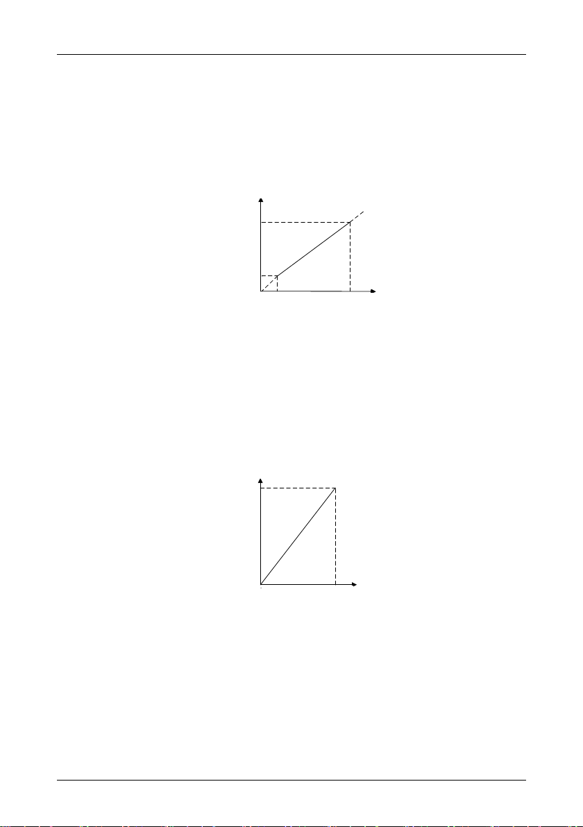
对应设定值
AI模拟量
曲线1最大输入
(C2-01)
曲线1最小输入
(C2-03)
曲线1最大输入对应
设定值(C2-02)
曲线1最小输入对应
设定值(C2-04)
0
PID输出
(b0-08)×(b0-06)
频率输出
最大值
Corresponding set value
Set value that corresponds to
maximum input of curve 1
(P22.02)
Set value that corresponds to
minimum input of curve 1
(P22.04)
Minimum input of
curve 1 (P22.03)
Maximum
input of curve
1 (P22.01)
AI analog
Frequency output
PID output
Maximum value
P10.08*P10.06
0
E5 User Manual Chapter 5 Specification of Parameters
command, the frequency that corresponds to maximum value of the source should be
(P10.08●P10.06)
Example:
Select AI1 as auxiliary frequency command source (set P10.03 to 3) and set AI1 to curve 1
(unit's place of P22.00 is 0) as shown in Fig.5-2. In such a case, the frequency that
corresponds to the maximum input of curve 1 should be: (P22.02) ● [(P10.08) ● (P10.06)].
Fig. 5-1
When X6/DI pulse input is selected as auxiliary frequency command (set P10.03 to 6), the
frequency that corresponds to maximum DI input should be: (P22.25) ● [(P10.08) ● (P10.06)].
When PID is selected for auxiliary frequency command, the frequency that corresponds to
maximum value of PID output should be (P10.08) ● (P10.06).
PID output diagrammatic sketch is as shown in Fig.5-2.
Fig. 5-2
When P10.05 is set to 1 (relative to master frequency):
When AI1, AI2, RESERVED, or X6/DI pulse input is selected for auxiliary frequency
command source, the frequency that corresponds to maximum value of these sources should
be:
[master frequency ● (P10.06)].
Example:
- 77 -
Page 82

Chapter 5 Specification of Parameters E5 User Manual
P10.07
Computation of master
and auxiliary frequency
Range: 0~3
Factory default: 0
P10.08
Maximum frequency
Range: Upper limit frequency
~600.00Hz
Factory default:
50.00Hz
P10.09
Upper limit frequency
Range: Lower limit frequency ~
maximum frequency
Factory default:
50.00Hz
P10.10
Lower limit frequency
Range: 0.00Hz ~ upper limit
frequency
Factory default:
0.00Hz
0
PID输出
主给定值×(b0-06)
频率输出
最大值
Maximum value
PID output
Frequency output
Master command
value × (P10.06)
0
When selecting AI1 as auxiliary frequency command source (set P10.03 to 3) and setting AI1 to
curve 1 (unit's place of P22.00 is 0), the frequency that corresponds to maximum input of curve
1 should be: (P22.02) ● [master frequency ● (P10.06)].
When X6/DI pulse input is selected as auxiliary frequency command source (set P10.03 to
6), the frequency that corresponds to maximum DI input should be: (P22.25) ● [master
frequency ● (P10.06)].
When PID is selected for auxiliary frequency command, the frequency that corresponds to
maximum value of PID output should be [master frequency ● (P10.06)].
PID output diagram is as shown in Fig.5-3.
Fig. 5-3
0: Master + auxiliary
The sum of master and auxiliary frequency is taken as frequency command. Output result is
subject to limitation of upper and lower limit frequency.
1: Master - auxiliary
The difference between master and auxiliary frequency is taken as frequency command.
Output result is subject to limitation of upper and lower limit frequency.
2: Max {master, auxiliary}
Master frequency or auxiliary frequency (whichever has a larger absolute value) is taken as
frequency command. Output result is subject to limitation of upper and lower limit frequency.
3: Min {master, auxiliary}
Master frequency or auxiliary frequency (whichever has a smaller absolute value) is taken as
frequency command. Output result is subject to limitation of upper and lower limit frequency.
- 78 -
Page 83

E5 User Manual Chapter 5 Specification of Parameters
P10.11
Operation when command frequency
lower than lower limit frequency
Range: 0~2
Factory default: 0
输出频率
fmaxfNfHfL0
输出电压
VN
Output voltage
Output frequency
Output frequency
Maximum frequency of P10.08 is the maximum allowable output frequency of drive and is
indicated by fmax in the figure.
P10.09 upper limit frequency is the user-defined maximum allowable running frequency
and represented by fH in Fig. 5-4.
P10.10 lower limit frequency is user-defined minimum allowable running frequency and
marked with fL in Fig. 5-4.
In Fig. 5-4, fN represents rated frequency of motor while VN means the rated voltage of
motor.
Fig. 5-4
ATTENTION:
Maximum frequency, upper limit frequency and lower limit frequency should be set with care
in accordance with nameplate parameters of motor and operation requirements.
Jog and motor parameter identification is free from limitations of upper and lower limit
frequency.
In addition to limitation of upper limit frequency and lower limit frequency, the output
frequency is also subject to limitations of starting frequency, stop DC brake initial frequency,
skip frequency and other parameter settings.
The rank relation between maximum frequency, upper limit frequency and lower limit
frequency is shown as Fig. 5-4.
Upper and lower limit frequencies restrict actual output frequency to motor. If command
frequency is higher than upper limit frequency, the running would be at upper limit frequency.
In case command frequency is lower than lower limit frequency, the running should be in
accordance with the setting of P10.11.
0: Run at lower limit frequency
In case command frequency is lower than lower limit frequency, the running should be at
lower limit frequency.
1: Run at 0Hz
In case the frequency command is lower than lower limit frequency, the running should be at
0Hz.
- 79 -
Page 84

Chapter 5 Specification of Parameters E5 User Manual
P10.12
Time-delay of stop when
command frequency lower
than lower limit frequency
Range: 0.0s~6553.5s
Factory default:
0.0s
P10.13
Lower limit of skip
frequency band 1
Range: 0.00Hz ~ upper limit
frequency
Factory default:
0.00Hz
P10.14
Upper limit of skip
frequency band 1
Range: 0.00Hz ~ upper limit
frequency
Factory default:
0.00Hz
P10.15
Lower limit of skip
frequency band 2
Range: 0.00Hz ~ upper limit
frequency
Factory default:
0.00Hz
P10.16
Upper limit of skip
frequency band 2
Range: 0.00Hz ~ upper limit
frequency
Factory default:
0.00Hz
P10.17
Lower limit of skip
frequency band 3
Range: 0.00Hz ~ upper limit
frequency
Factory default:
0.00Hz
P10.18
Upper limit of skip
frequency band 3
Range: 0.00Hz ~ upper limit
frequency
Factory default:
0.00Hz
Frequency after adjustment
Skip frequency band 3
Skip frequency band 2
Skip frequency band 1
Command frequency
P0.18
P0.17
P0.16
P0.15
P0.14
P0.13
2: Stop
If frequency command is lower than lower limit frequency, stop would be activated after the
time delay set by P10.12. When lower limit frequency is 0, this limitation is invalid.
ATTENTION:
This parameter is disabled under PID control mode.
When P10.11 is set to 2, and command frequency is lower than lower limit frequency, the drive
will stop running after this parameter value.
Skip frequency is a function designed to prevent the drive running at resonance zone of
mechanical system.
At most 3 skip zones can be defined. See Fig.5-5.
Once parameters of skip zones are set, the output frequency of the drive would
automatically get out of these skip zones even if the command frequency is within these zones.
Fig.5-5
- 80 -
Page 85

E5 User Manual Chapter 5 Specification of Parameters
P10.19
Jog frequency
Range: 0.00Hz ~ upper limit
frequency
Factory default:
5.00Hz
P11.00
Run command
Range: 0~2
Factory default: 0
f1
运行频率
时间
t1
t2
Running frequency
Time
ATTENTION:
Output frequency of drive can normally pass through skip zones during Accel and Decel.
This parameter sets the running frequency during jog. Jog Accel time is set by parameter
P12.10 while its Decel time by parameter P12.11.
Jog run command control could be performed through keypad, control terminals or
communication input.
Multifunction MF key can be set as forward jog or reverse jog key through parameter
P70.00.
Jog can be realized using "forward jog terminal” and "reverse jog terminal” of DI.
Jog can be realized via communication input. See drive communication protocol for further
information.
See Jog diagrammatic sketch Fig. 5-6.
Fig.5-6
Thereof:
f1 is jog frequency P10.19
t1 represents the ACC time from zero to jog frequency; t1 = (P12.10) ● f1/(P10.08); P10.08
is the maximum frequency.
t2 is the DEC time from jog frequency to 0; t2 = (P12.11) ● f1/(P10.08).
ATTENTION:
Set value of jog frequency is free from limitations of upper and lower limit frequency.
Jog is started from starting frequency and its start is not subject to limitation by P11.05.
Group 11 Start/Stop Control
This parameter sets run command source. Run commands include "start, stop, forward and
reverse", etc.
0: Keypad control
- 81 -
Page 86

Chapter 5 Specification of Parameters E5 User Manual
P11.01
Binding of run command
and frequency
command
Range: 000 ~ AAA
Factory default:
000
Control run command through RUN, STOP/RESET and MF keys on keypad (set
multifunction key MF to JOG by P70.00). Refer to Chapter 3 about the operation of keypad.
1: Terminal control
Control run command via DI terminals. Perform FORWARD and REVERSE by DI terminals.
The control mode are two-wire mode and three-wire mode selectable. See Group P20for
details of designation and wiring regulation of DI terminals.
2: Communication control
Master device is able to control run command through built-in RS485 serial communication
interface of drive. Refer to parameters Group P60 and appendix for further information about
programming.
Run command from keypad, terminals and communication can be switched by terminals "run
command switched to keypad control", "run command switched to terminal control" and "run
command switched to communication control".
Multifunction key MF can be set to "run command sources shifted" key through parameter
P70.00. When MF key is pressed under this setting, run command will be shifted during keypad
control, terminal control and communication control circularly.
This parameter defines the bundled combination of three run command sources and frequency
command sources with the purpose of facilitating simultaneous switching.
For example: frequency command source AI1 (unit's place of P11.01 is set to 3) bundled
with keypad control, while the frequency command source X6/DI pulse input (ten's place of
P11.01 is set to 6) bundled with terminal control. In such a case, when run command is
controlled by keypad, frequency command source would be AI1, while when run command is
controlled via terminals, frequency command source will be automatically switched to X6/DI
pulse input.
Unit's place: frequency command source bundled under keypad control
0: No binding
1: Digital setting (P10.02) + ∧/∨ adjustment on keypad
2: Digital setting (P10.02) + terminal UP/DOWN adjustment
3: Analog input AI1
4:Aanalog input AI2
5: Reserved
6: X6/DI pulse input
7: Process PID output
8: Simple PLC
9: Multi-step frequency
A: Communication input
- 82 -
Page 87
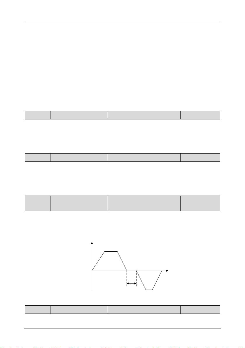
E5 User Manual Chapter 5 Specification of Parameters
P11.02
Running direction
Range: 0~1
Factory default: 0
P11.03
Reverse disabled
Range: 0~1
Factory default: 0
P11.04
Dead time of forward
and reverse
Range: 0.0s ~ 3600.0s
Factory default:
0.0s
P11.05
Start method
Range: 0~2
Factory default: 0
输出频率
时间
t
Output frequency
Time
Refer to parameter P10.01 for details regarding above-mentioned sources of frequency
command.
Decade: frequency command source bundled under terminal control (same as unit's place)
Hundreds place: frequency command source bundled under communication control (same
as unit's place)
ATTENTION:
Different run command sources can be bundled with the same frequency command
source.
The priority of frequency command sources bundled with run command overrides Group
P10.
This parameter applies to run command controlled by keypad, and disabled under terminal and
communication control.
0: Forward
1: Reverse
0: Reverse enabled
1: Reverse disabled
In some applications, reverse is likely to result in equipment damage. This parameter is used to
prevent reverse running.
The dead time with 0Hz output during the transition from forward to reverse, or from reverse to
forward is indicated by letter "t" in Fig.5-7.
Fig.5-7 Dead time between forward and reverse
- 83 -
Page 88

Chapter 5 Specification of Parameters E5 User Manual
P11.06
Start frequency
Range: 0.00Hz ~ upper limit
frequency
Factory default:
0.00Hz
P11.07
Holding time of start
frequency
Range: 0.0s ~ 3600.0s
Factory default:
0.0s
P11.08
DC braking current
when start
Range: 0.0%~100.0%
Factory default:
0.0%
P11.09
DC braking time when
start
Range: 0.00s~30.00s
Factory default:
0.00s
P11.10
Speed search current
Range: 0~200.0%
Factory default:
100.0%
This parameter takes effect during the process of transition from stop status to running status.
0: From start frequency
When drive starts to run from stop status, it starts from start frequency (P11.06) and keeps
this frequency for a period of time set by P11.07, and then accelerated to command
frequency in accordance with the Accel method and time.
1: DC braking then start
To make the motor stop completely, the drive will perform DC braking with a certain period of
time, as specified by P11.08 and P11.09, then start from start frequency (P11.06), keeping a
period of time as specified by P11.07, and then Accelerate to command frequency.
2: Start based on speed search (flying start)
Search the actual speed of motor that is rotating and perform smooth start from the searched
speed. This start method is applicable to restart on momentary power loss, the start of fan
which is still rotating, etc. To assure the accuracy of speed search, please correctly set motor
parameters, and P11.10~P11.12.
Start frequency is initial output frequency of drive start from stop status. Start frequency holding
time is the continuous running time with start frequency. After this holding time, the drive will
Accelerate to command frequency. Usually appropriate start frequency and holding time assure
the starting torque of heavy-duty load.
ATTENTION:
Provided that command frequency is lower than start frequency, drive output frequency is 0
Hz. Start frequency also works on the transition of forward and reverse, but starting
frequency holding time is disabled during transition between forward and reverse. Accel time
of Group P12 excludes holding time of start frequency.
When the motor is started by the method "DC braking then start", it is essential to set the these
two parameters.100% corresponds to rated current of drive. If braking time is set to 0.0s, DC
braking when start shall be disabled.
100% corresponds to rated current of the drive. When output current of drive is less than this
- 84 -
Page 89

E5 User Manual Chapter 5 Specification of Parameters
P11.11
Sped search Decel time
Range: 0.1s~20.0s
Factory default:
2.0s
P11.12
V/f coefficient during
speed search
Range: 20.0%~100.0%
Factory default:
100.0%
P11.13
Stop method
Range: 0~2
Factory default: 0
P11.14
Start frequency of DC
brake stop
Range: 0.00Hz ~ upper limiting
frequency
Factory default:
0.00Hz
P11.15
DC brake current
Range: 0.0%~100.0%
Factory default:
0.0%
P11.16
DC brake time
Range: 0.00s~30.00s
Factory default:
0.00s
parameter value, it will be deemed that the output frequency of drive has been kept in step with
motor speed and the search action finished.
This parameter sets the output frequency Decel time of speed search action. This time means
the time required for Decel from maximum frequency to 0.The shorter the speed search Decel
time is, the faster the search will be. However, excessively rapid search may bring about
inaccuracy of search result.
This parameter is set to suppress the output current of speed search, and improve the reliability
of speed search, by multiplying this value on the basis of motor V/f curve.
0: Ramp to stop
Upon the receipt of stop command, drive will gradually decrease output frequency according
to the set Decel time, and stop when frequency attains 0.
1: Coast to stop
Upon the receipt of stop command, drive will immediately lock the output and the motor will
stop with its mechanical inertia.
2: Ramp to stop + DC brake
Upon the receipt of stop command, drive will decrease output frequency in accordance with
the rate of Decel time setting. Once the output frequency attains set value of P11.14, DC
braking will be enabled, and the drive will stop after the finish of DC braking.
During the process “ramp to stop + DC braking", DC brake would be started when output
frequency attains set value of P11.14. P11.15 defines brake level, in amps, applied to the
motor. 100% corresponds to rated current of drive. P11.16 sets the length of time that DC
brake current is “injected” into the motor when P11.13 is set to 2. In case brake time is set to
0.0s, DC brake shall be disabled.
If "DC brake stop" terminal enabled, time length of this terminal or P11.16 set time
(whichever is longer) would be taken as stop brake time.
- 85 -
Page 90

Chapter 5 Specification of Parameters E5 User Manual
P11.17
Overexcitation brake
Range: 0~1
Factory default: 1
P11.18
Dynamic brake
Range: 0~1
Factory default: 0
P11.19
Dynamic brake
threshold voltage
Range: 650V~750V
Factory default:
720V
P11.20
Auto restart when power up
again after power loss
Range: 0~1
Factory default: 0
0: Disabled
1: Enabled
When overexcitation brake is enabled in case of stop by Decel, the motor shall transform the
electric energy generated during Decel into heat energy by increasing magnetic flux so as to
attain rapid stop. If this parameter is enabled, the Decel time will be shortened. If
overexcitation brake is disabled, the Decel current of motor will decrease and the Decel time
will be lengthened.
0: Disabled
1: Enabled
When dynamic brake is enabled, the electric energy generated during Decel shall be
converted into heat energy consumed by brake resistor, so as to attain rapid Decel. This
brake method applies to brake of high-inertia load or the situations that require quick stop. In
such a case, it is necessary to select appropriate dynamic brake resistor and brake unit. The
drives equal and below 15kW are provided with a standard built-in brake unit. Built-in brake
unit is optional for drives 18.5kW~45kW.
This parameter takes effect only to the drives with built-in brake unit.
If P11.18 is set to 1: when bus voltage of drive attains the value of P11.19, dynamic brake
shall perform. The energy shall be rapidly consumed through brake resistor. This value is used
to regulate the brake effect of brake unit.
Defines the drive status when power up again after power loss during running
0: Disabled
The drive will not run automatically when power is up after power loss.
1: Enabled.
When run command is controlled by keypad or communication, the drive will run
automatically when power is up again after power loss. When run command is controlled by
terminals, the drive will run automatically only if ON signal from run command terminal is
detected
ATTENTION:
Enable this parameter with caution for safety consideration.
- 86 -
Page 91

E5 User Manual Chapter 5 Specification of Parameters
P11.21
Waiting time of auto restart
when power up again
Range: 0.0s~10.0s
Factory default:
0.0s
P12.00
Accel/Decel time
resolution
Range: 0~2
Factory default: 1
P12.01
Accel time 1
Range: 0s~60000s
Factory default:
6.0s
P12.02
Decel time 1
Range: 0s~60000s
Factory default:
6.0s
P12.03
Accel time 2
Range: 0s~60000s
Factory default:
6.0s
P12.04
Decel time 2
Range: 0s~60000s
Factory default:
6.0s
P12.05
Accel time 3
Range: 0s~60000s
Factory default:
6.0s
P12.06
Decel time 3
Range: 0s~60000s
Factory default:
6.0s
P12.07
Accel time 4
Range: 0s~60000s
Factory default:
6.0s
P12.08
Decel time 4
Range: 0s~60000s
Factory default:
6.0s
This time setting is on the basis of work restoration time of relative devices in the system when
power is up again after power loss, if P11.20 is set to 1.
Group P12 Accel/Decel Parameters
0: 0.01s; the setting range of Accel/Decel time is 0.00s~600.00s
1: 0.1s; the setting range of Accel/Decel time is 0.0s~6000.0s
2: 1s; the setting range of Accel/Decel time is 0s~60000s
Accel/Decel time resolution takes effect on P12.01~P12.11.
These parameters P12.01~P12.08 set the rate of Accel/Decel for speed increase/decrease.
Maximum Freq (P10.08) / Accel time X = Accel Rate X
Maximum Freq (P10.08) / Decel time X = Decel Rate X
As the formula sets forth above, Accel time means required time for drive to Accelerate to
maximum frequency P10.08 from zero frequency, while Decel time refers to the time required
for drive to Decelerate to zero frequency from maximum frequency P10.08.
These four types of Accel/Decel time can be selected through the ON/OFF combination of DI
terminals" Accel/Decel time determinant 1" and " Accel/Decel time determinant 2". See
- 87 -
Page 92

Chapter 5 Specification of Parameters E5 User Manual
Accel/Decel time
determinant 2
Accel/Decel time
determinant 1
Accel/Decel time
OFF
OFF
Accel/Decel time 1(P12.01,
P12.02)
OFF
ON
Accel/Decel time 2(P12.03,
P12.04)
ON
OFF
Accel/Decel time 3(P12.05,
P12.06)
ON
ON
Accel/Decel time 4(P12.07,
P12.08)
P12.09
Decel time for
emergency stop
Range: 0s~60000s
Factory default:
6.0s
P12.10
Jog Accel time
Range: 0s~60000s
Factory default:
6.0s
P12.11
Jog Decel time
Range: 0s~60000s
Factory default:
6.0s
P12.12
Accel/Decele curve
Range: 0~4
Factory default: 0
Table5-2.
Table5-2
ATTENTION:
When the drive is running under simple PLC, the Accel time and Decel time are determined
by simple PLC related parameters, not by the DI terminals. See Group P52 for details.
When Accel/Decel of broken-line style is selected, Accel/Decel time is automatically
switched to Accel/Decel time 1 and 2 according to switching frequency (P12.13 and
P12.14).
Under this circumstance, Accel/Decel time selection terminals are disabled.
In case of emergency stop via multifunction MF key on keypad (MF key has been set to
emergency stop 1 through parameter P70.00), or via DI terminal "emergency stop", Decel is
conducted according to this time. This parameter sets the rate of Decel for speed decrease,
similar with P12.01~P12.08.
P12.10 and P12.11 set the rate of Accel/Decel of Jog, similar with P12.01~P12.08.
0: Linear Accel/Decel
Outputs frequency increases or decreases with a constant rate as shown in Fig.5-8.
- 88 -
Page 93

E5 User Manual Chapter 5 Specification of Parameters
输出频率
时间
fmax
t2
(减速时间)
t1
(加速时间)
输出频率
t1
(加速时间)
f
b2-14
b2-13
t2
(加速时间)
t3
(减速时间)
t4
(减速时间)
时间
Output frequency
Output frequency
Accel time
Decel time
Time
Time
Accel time
Accel time
Decel time
Decel time
P12.14
P12.13
Fig.5-8fmax is maximum frequency P10.08.
1: Broken-line Accel/Decel
Accel/Decel time is shifted based on output frequency during Accel/Decel.
When output frequency during Accel is higher than or equal to P12.13 (Accel time
switching frequency of broken-line Accel/Decel), P12.01 (Accel time 1) is enabled. When
lower than P12.13, P12.03 (Accel time 2) will be enabled.
When output frequency during Decel is higher than or equal to P12.14 (Decel time
switching frequency of broken-line Accel/Decel), P12.02 (Decel time 1) is enabled. When
lower than P12.14, P12.04 (Decel time 2) will be enabled.
ATTENTION:
When broken-line Accel/Decel is enabled, " Accel/Decel time determinant 1" and "
Accel/Decel time determinant 2" will be disabled.
Broken-line Accel/Decel is as shown in Fig.5-9.
Fig.5-9
t1 = (P12.03)●(P12.13)/(P10.08) t2 =(P12.01)●[f-(P12.13)]/(P10.08)
t3 = (P12.02)●[f-(P12.14)]/(P10.08) t4 = (P12.04)●(P12.14)/(P10.08)
f is current frequency command, and P10.08 is maximum frequency.
2: S-curve Accel/Decel A
By adding a period of S-curve time to the initial and ending segments of Accel/Decel, it can
improve the smoothness of start/stop and prevent mechanical impact. See Fig.5-10:
- 89 -
Page 94

Chapter 5 Specification of Parameters E5 User Manual
Output frequency
Time
Linear
Accel
Fig.5-10
Accel/Decel rate changes gradually at the initial and ending segments of S-curve time. At the
middle segment of S-curve, it is linear Accel/Decel rate, which is determined by enabled
Accel/Decel time 1~4. Therefore, the actual Accel/Decel time is longer than linear Accel/Decel
if this parameter value is selected.
Actual Accel time = linear Accel time + (Time of initial segment of Accel S-curve
+ Time of last segment of Accel S-curve)/2
Actual Decel time = linear Decel time + (Time of initial segment of Decel S-curve + Time
of last segment of Decel S-curve)/2
Example:
Assuming that the maximum frequency P10.08 is 50Hz and the Accel time set is 6s, the linear
Accel time from initial status 10Hz to 40Hz = 6s ● (40Hz-10Hz)/50Hz = 3.6s
Assuming P12.15 = 0.20s and P12.16 = 0.40s, the actual Accel time under “S-curve
Accel/Decel A” = 3.6s + (0.20s + 0.40s)/2 = 3.9s.
ATTENTION:
Provided the above-noted calculated linear Accel time is less than (Time of initial segment of
Accel S-curve + Time of last segment of Accel S-curve)/2, there will not be linear part.
Decel is the same as above.
3: S-curve Accel/Decel B
Schematic diagram is shown as Fig.5-11:
- 90 -
Page 95

Output frequency
Time
Linear
Accel
E5 User Manual Chapter 5 Specification of Parameters
Fig.5-11
S-curve time at initial segment of Accel is (P12.19●t1) in the figure, in which the Accel rate
increases progressively. In this period, the S-curve time at ending segment is (P12.20●t1) and
the Accel rate decreases gradually. At the middle of t1, it is linear Accel with a constant rate
which is adjusted automatically based on the setting of P12.19 and P12.20.
Decel period t2 is similar as above.
Make sure the sum of proportions of initial and ending segments is no more than 100%, i.e.
the sum of set values of P12.19 and P12.20 should not exceed 100.0%, while that of P12.21
and P12.22 should not exceed 100%.
Example:
Assuming that the maximum frequency P10.08 is 50Hz and the Accel time setting is 6s, the
linear Accel time required for Accel from initial status 10Hz to 40Hz = 6s ● (40Hz-10Hz)/50Hz =
3.6s
Assuming that P12.19 = 20.0% and P12.20 = 30.0%,
Initial segment of Accel S-curve should be 20.0% ● 3.6s = 0.72s; Ending segment of Accel
S-curve should be 30.0% ● 3.6s = 1.08s; linear Accel time at middle segment should be 3.6s -
0.72s - 1.08s = 1.8s.
Difference between S-curve Accel/Decel A and B:
Middle-segment Accel/Decel rate of S-curve Accel/Decel A is determined by the selected
Accel/Decel time 1~4, not subject to the effect of S-curve time span, therefore the total
Accel/Decel time changes with the variation of setting of S-curve time.
When some certain Accel/Decel time is selected for S-curve Accel/Decel B, the total time
of Accel/Decel is constant, but with different proportion of initial part and ending part, the rate of
linear part as well as the shape of S-curve will changes.
4: S-curve Accel/Decel C
The rated frequency of the motor is taken as inflection point of this S-curve, and the set
Accel/Decel time is:
Accel/Decel rate = Motor rated frequency / Accel/Decel time (√)
NOT Accel/Decel rate = Maximum frequency / Accel/Decel time (●)
When command frequency is higher than rated frequency of motor, the Accel/Decel time is
- 91 -
Page 96

Chapter 5 Specification of Parameters E5 User Manual
P12.13
Accel time switching
frequency of broken-line
Accel/Decel
Range:
0.00Hz~maximum
frequency
Factory default:
0.00Hz
P12.14
Decel time switching
frequency of broken-line
Accel/Decel
Range:
0.00Hz~maximum
frequency
Factory default:
0.00Hz
P12.15
Time of initial segment of
Accel S-curve
Range: 0.00s~60.00s
Factory default: 0.20s
P12.16
Time of last segment of
Accel S-curve
Range: 0.00s~60.00s
Factory default: 0.20s
输出频率
时间
f
fN
Output frequency
Time
automatically adjusted by reducing output torque of the motor. This is applicable to the situation
in which short Accel/Decel time is required during the speed range higher than rated frequency
of the motor.
Diagram of S-curve C is shown as Fig.5-12:
Fig.5-12
f: Command Freq
fN: Rated Freq of the motor
When P12.12 is set to 1:
P12.01 (Accel time 1) is enabled when output frequency during Accel is more than or equal
to set value of P12.13, while P12.03 (Accel time 2) is enabled when output frequency during
Accel is less than set value of P12.13.
b2- 02 (Decel time 1) is enabled when output frequency during Decel is more than or equal
to set value of P12.14, while P12.04 (Decel time 2) is enabled when output frequency during
Accel is less than set value of P12.14.
ATTENTION:
When broken-line Accel/Decel is selected, terminals "Accel/Decel time determinant 1" and
"Accel/Decel time determinant 2" will be disabled.
- 92 -
Page 97

E5 User Manual Chapter 5 Specification of Parameters
P12.17
Time of initial segment of
Decel S-curve
Range: 0.00s~60.00s
Factory default: 0.20s
P12.18
Time of last segment of
Decel S-curve
Range: 0.00s~60.00s
Factory default: 0.20s
P12.19
Proportion of initial
segment of Accel S-curve
Range: 0.0%~100.0%
Factory default: 20.0%
P12.20
Proportion of last segment
of Accel S-curve
Range: 0.0%~100.0%
Factory default: 20.0%
P12.21
Proportion of initial
segment of Decel S-curve
Range: 0.0%~100.0%
Factory default: 20.0%
P12.22
Proportion of last segment
of Decel S-curve
Range: 0.0%~100.0%
Factory default: 20.0%
P20.00
Enabled condition of run
command terminals when
power up
Range: 0~1
Factory default: 0
These four parameters are enabled when P12.12 is set to 2.
These four parameters are enabled when P12.12 is set to 3.
ATTENTION:
The sum of set values of P12.19 and P12.20 should not exceed 100.0%. The same to
P12.21 and P12.22.
Group P20 Digital Input
This parameter is only for digital terminals with parameter value 1~4 (forward/reverse jog, and
forward/reverse running), and also is only for initial running after power up.
0: Trigger edge detected + ON detected
When run command is controlled by terminals, the drive will start to run when it detects that
the terminal jumps from OFF to ON and is kept ON after power up.
If run command terminal is in ON state before power up, the drive will not run after
power up. Under this circumstance, only when the ON state is shifted to OFF and then ON
again, and maintain ON, the drive will start running.
1: ON detected
When run command is controlled by terminals, the drive will start to run when detecting the
command terminal at ON state after power up.
ATTENTION:
When “1: ON detected” selected, the drive will start to run after power up as long as ON of run
command terminal detected. Make sure of the safety of personnel and equipment before this
setting.
- 93 -
Page 98

Chapter 5 Specification of Parameters E5 User Manual
P20.01
Function of terminal X1
Range: 0~99
Factory default: 3
P20.02
Function of terminal X2
Range: 0~99
Factory default: 4
P20.03
Function of terminal X3
Range: 0~99
Factory default: 1
P20.04
Function of terminal X4
Range: 0~99
Factory default: 23
P20.05
Function of terminal X5
Range: 0~99
Factory default: 11
P20.06
Function of terminal X6
Range: 0~99
Factory default: 0
P20.07
Reserved
Reserved
Reserved
P20.08
Function of terminal AI1 (Digital
enabled)
Range: 0~99
Factory default: 0
P20.09
Function of terminal AI2 (Digital
enabled)
Range: 0~99
Factory default: 0
P20.10
Reserved
Reserved
Reserved
Param
value
Function
Param
value
Function
0
No function
33
PID adjustment direction
1
JOG forward
34
PID paused
2
JOG reverse
35
PID integration paused
3
Running forward (FWD)
36
PID parameter switch
4
Running reverse (REV)
37
Count input
5
Three-wire control
38
Count clear
6
Running suspended
39
Length count
7
External stop
40
Length clear
8
Emergency stop
41
Reserved
9
Stop command + DC brake
42
Reserved
10
DC brake stop
43
Reserved
11
Coast to stop
44
Reserved
12
Terminal UP
45
Reserved
13
Terminal DOWN
46
Reserved
14
UP/DOWN (including ∧/∨ key)
47
Reserved
Analog input terminals AI1, AI2 and RESERVED can also be used as digital input terminals set
by P20.08~P20.10. When AI1, AI2 and RESERVED are used as analog input, P20.08~P20.10
shall be set to 0.
Parameter setting of digital input is as shown in Digital input functions
Digital input functions
- 94 -
Page 99

E5 User Manual Chapter 5 Specification of Parameters
Param
value
Function
Param
value
Function
adjustment clear
15
Multi-step frequency terminal 1
48
Reserved
16
Multi-step frequency terminal 2
49
Reserved
17
Multi-step frequency terminal 3
50
Reserved
18
Multi-step frequency terminal 4
51
Reserved
19
Accel/Decel time determinant 1
52
Reserved
20
Accel/Decel time determinant 2
53
Reserved
21
Accel/Decel disabled(ramp stop
not inclusive)
54
Reserved
22
External fault input
55
Reserved
23
Fault reset (RESET)
56~62
Reserved
24
Pulse input (valid only for X6/DI)
63
Simple PLC paused
25
Motor 1/2 switchover
64
Simple PLC disabled
26
Reserved
65
Clear simple PLC stop
memory
27
Run command switched to
keypad control
66
Start wobble frequency
28
Run command switched to
terminal control
67
Clear wobble frequency status
29
Run command switched to
communication control
68
Running prohibited
30
Frequency command pattern
shift
69
DC injection braking at running
31
Master frequency command
switched to digital setting P10.02
70~99
Reserved
32
Auxiliary frequency command
switched to digital setting P10.04
0: No function
1: JOG forward
Perform jog forward through terminals. Jog frequency is set by P10.19, jog Accel time set by
P12.10, and jog Decel time set by P12.11. Refer to P20.00 for enabled conditions on initial
power up.
2: JOG reverse
Perform jog reverse through terminals. Jog frequency is set by P10.19, jog Accel time set by
- 95 -
Page 100

Chapter 5 Specification of Parameters E5 User Manual
P12.10, and jog Decel time set by P12.11. Refer to P20.00 for enabled conditions on initial
power up.
3: Forward (FWD)
Terminals control forward running of the drive. Refer to P20.00 for enabled conditions on
initial power up.
4: Reverse (REV)
Terminals control reverse running of the drive. Refer to P20.00 for enabled conditions on
initial power up.
5: Three-wire control
There are two-wire control and three-wire control about Forward (FWD) and reverse (REV).
In case of three-wire control is enabled, "three-wire control" terminal is activated. For details,
refer to P20.19 (FWD/REV terminal control mode).
6: Running suspended
When "running suspended" terminal is enabled during the running, the drive will block the
output and perform zero-frequency running. Once "running suspended" terminal becomes
disabled, the drive restores the running.
7: External stop
No matter which type of P11.00 is set to, the drive will stop by enabled “external stop”
terminal, in the manner of stop mode.
8: Emergency stop
When "emergency shutdown" is enabled, the drive will stop in accordance with Decel time
set by P12.09. Please set P12.09 to an appropriate value so as to minimize the Decel time
for emergency stop.
9: Stop command + DC brake
The drive performs ramp-down stop when "stop command+ DC brake" terminal is enabled. It
will perform DC brake when output frequency attains brake starting frequency. Brake starting
frequency and brake current are set by P11.14 and P11.15. Brake time is determined by the
maximum of P11.16 and the lasting time of this terminal.
10: DC brake stop
The drive performs “ramp to stop + DC brake” (same as P11.13 is set to 2) when “DC brake
stop” is enabled, in the manner set by P11.14, P11.15 and P11.16.
11: Coast to stop
When “coast to stop” terminal is enabled, the drive will immediately cut off its output and the
motor will coast to stop.
12: Terminal UP
13: Terminal DOWN
Terminals are used to increase and decrease the command frequency. The command
frequency will be increased and decreased when "digital setting + terminal UP/DOWN
adjustment" is enabled. The adjustment “step size” is set by P20.18. Refer to P20.17 for
Terminal UP/DOWN frequency adjustment treatment.
14: UP/DOWN (including ∧/∨ key) adjustment clear
- 96 -
 Loading...