

Page 1

Models: D49M30SB, D49M30BLS, D49M36SB, D49M36BLS, D49M48SB
Downdraft Ventilator
For use with these blowers
(purchase blowers separately):
Model PF6* - Flex Blower - Interior
Models EB6, EB9*, EB12*, or EB15* - Exterior
Models ILB6, ILB9 or ILB11* - In-Line
* Recommended models
READ AND SAVE THESE INSTRUCTIONS
In U.S.A., register your product online at: www.BestRangeHoods.com
In Canada, register your product online at: www.BestRangeHoods.ca
Français p. 38
Español p. 75
Page 2

Table of Contents
Safety Information .................................................................................................................................................................................. 3
Contents .................................................................................................................................................................................................. 4
Electrical Specifi cations ......................................................................................................................................................................... 4
Tools Needed ........................................................................................................................................................................................... 4
Planning
Before You Begin ............................................................................................................................................................................... 5
Taking Measurements........................................................................................................................................................................ 5
Ducting Confi gurations ...................................................................................................................................................................... 5
Cabinet Cutouts .................................................................................................................................................................................11
Electrical Outlet Location ...................................................................................................................................................................13
Preparing the Downdraft
Downdraft Preparation ....................................................................................................................................................................... 14
Side, Below or Rear Rectangular Ducting ........................................................................................................................................... 14
Side, Below or Rear Round Ducting .................................................................................................................................................... 14
Front Ducting .....................................................................................................................................................................................15
Electrical Panel in Remote Location ...................................................................................................................................................16
Final Assembly ................................................................................................................................................................................... 16
Installation
Cutting Countertop Opening ............................................................................................................................................................... 17
Install Housing into Cabinet ................................................................................................................................................................ 18
Installing Finish Trim ..........................................................................................................................................................................19
Installing Ductwork ............................................................................................................................................................................19
Electrical Wiring Installation
Flex Blower Only ................................................................................................................................................................................20
Exterior or In-Line Blower Only ..........................................................................................................................................................11
Appliance Installation/Operation ........................................................................................................................................................... 22
Use and Care ........................................................................................................................................................................................... 23
Optional Accessories .............................................................................................................................................................................. 24
Appendices A-I ....................................................................................................................................................................................... 26
Warranty .................................................................................................................................................................................................35
Service Parts ...........................................................................................................................................................................................36
2
Page 3
Safety Information
WARNING
TO REDUCE THE RISK OF FIRE, ELECTRIC SHOCK, OR
INJURY TO PERSONS, OBSERVE THE FOLLOWING:
1. Use this unit only in the manner intended by the manufacturer.
If you have questions, contact the manufacturer at the address
or telephone number on the back page.
2. Before servicing or cleaning unit, switch power off at
service panel and lock the service disconnecting means to
prevent power from being switched on accidentally. When the
service disconnecting means cannot be locked, securely fasten
a prominent warning device, such as a tag, to the service
panel.
3. Installation work and electrical wiring must be done by a
qualifi ed person(s) in accordance with all applicable codes and
standards, including fi re-rated construction codes and
standards.
4. Suffi cient air is needed for proper combustion and exhausting
of gases through the fl ue (chimney) of fuel burning equipment
to prevent backdrafting. Follow the heating equipment
manufacturer’s guideline and safety standards such as those
published by the National Fire Protection Association (NFPA),
and the American Society for Heating, Refrigeration and Air
Conditioning Engineers (ASHRAE), and the local code
authorities.
5. When cutting or drilling into wall or ceiling, do not damage
electrical wiring and other hidden utilities.
6. Ducted fans must always be vented to the outdoors.
7. To reduce the risk of fi re, use only metal ductwork.
8. Do not install this product with the activating switch directly
behind a burner or element. Minimum distance between the
switch and the edge of the burner should be 4 inches.
9. Loose-fi tting or hanging clothing should never be worn when
operating this appliance. They may be ignited by burners/
elements on cooktop.
10. Children should not be left alone or unattended in the area
where this appliance is in use.
11. This unit must be grounded.
12. When applicable local regulations comprise more restrictive
installation and/or certifi cation requirements, the aforementioned
requirements prevail on those of this document and the installer
agrees to conform to these at his own expense.
TO REDUCE THE RISK OF A RANGE TOP GREASE FIRE:
a) Never leave surface units unattended at high settings. Boil
overs cause smoking and greasy spillovers that may ignite.
Heat oils slowly on low or medium settings.
b) Always turn hood ON when cooking at high heat or when
cooking fl aming foods.
c) Clean ventilating fans frequently. Grease should not be allowed
to accumulate on fan or fi lter.
d) Use proper pan size. Always use cookware appropriate for the
size of the surface element.
WARNING
TO REDUCE THE RISK OF INJURY TO PERSONS IN THE
EVENT OF A RANGE TOP GREASE FIRE, OBSERVE THE
FOLLOWING:
1. SMOTHER FLAMES with a close-fi tting lid, cookie sheet, or
metal tray, then turn off the burner. BE CAREFUL TO PREVENT
BURNS. If the fl ames do not go out immediately, EVACUATE AND
CALL THE FIRE DEPARTMENT.
2. NEVER PICK UP A FLAMING PAN - You may be burned.
3. DO NOT USE WATER, including wet dishcloths or towels a violent steam explosion will result.
4. Use an extinguisher ONLY if:
A. You know you have a Class ABC extinguisher, and you
already know how to operate it.
B. The fi re is small and contained in the area where it started.
C. The fi re department is being called.
D. You can fi ght the fi re with your back to an exit. Based on
“Kitchen Fire Safety Tips” published by NFPA.
CAUTION
1. For indoor use only.
2. For general ventilating use only. Do not use to exhaust
hazardous or explosive materials and vapors.
3. To avoid motor bearing damage and noisy and/or unbalanced
impellers, keep drywall spray, construction dust, etc. off
power unit.
4. Clean fi lters and grease-laden surfaces frequently.
5. Do not repair or replace any part of this appliance unless
specifi cally recommended in this manual. All other servicing
should be done by a qualifi ed technician.
6. Please read specifi cation label on product for further
information and requirements.
7. When installing, servicing or cleaning the unit, it is
recommended to wear safety glasses and gloves.
8. To reduce the risk of fi re and electric shock, install this
downdraft only with blower models shown below. Other blower
models cannot be substituted. (Blowers sold separately).
Flex Blower Model PF6, Exterior Blower Models EB6, EB9,
EB12, or EB15 In-Line Blower Models ILB6, ILB9, or ILB11.
INSTALLER: Save this manual for Electrical Inspector
and Homeowner to use.
3
Page 4
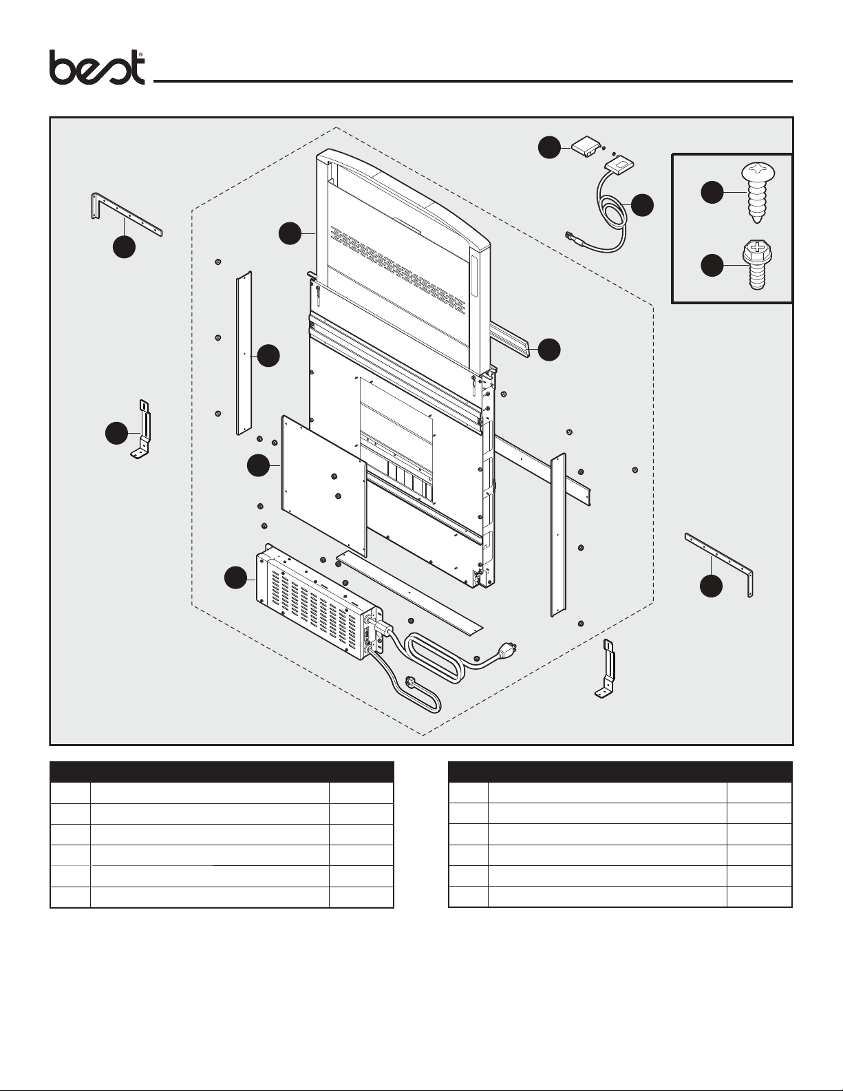
Contents
C
x8
D
AA
A
x4
F
x2
E
G
H
ELECTRICAL
SPECIFICATIONS
Model PF6 - Internal Flex:
120 VAC • 60 Hz • 3.0 A
Models EB6, EB9, EB12, or EB15 - Exterior
Models ILB6, ILB9 or ILB11 - In-Line
120 VAC • 60 Hz • 6.0 A (max.)
B
x2
BB
J
I
Part Description Quantity
A Upper support bracket (left) 1
B Downdraft ventilator housing 1
C End cap trim (left) 1
D End cap trim–up button (right) 1
E Support leg 2
F Discharge cover 4
Part Description Quantity
G Front panel cover 1
H Electrical panel 1
I Upper support bracket (right) 1
J Flip door 1
AA #10 x .50 Phillips round head screw 8
BB #8-18 x .375 Phillips screw 2
Tools Needed
Measuring tape, pencil, Phillips screwdriver #2, nut drivers (11/32", 3/8", 7/16"), saw, spirit-level, tin snips, work gloves, and aluminum tape.
(DO NOT use insulating tape.)
4
Page 5
Before You Begin
Planning
Due to its fl exible design, this downdraft system can be used to
exhaust airborne contaminants when cooking with a variety of gas
or electric cooking appliances - including cooktops, rangetops,
slide-in ranges and free-standing ranges.
It can be mounted in island, peninsula, or conventional wall
locations. The blower (purchase separately) and electrical panel
can be mounted to the downdraft unit, inside the cabinet, or in a
convenient remote location.
This unit can be easily installed following these basic steps:
• Cut out the countertop opening.
• Mount the unit in the cabinet.
• Install the blower and electrical panel.
• Connect the ductwork and electrical.
• Install the trim.
• Install the cooking appliance.
Note: the high level of air ow of this appliance may affect the
gas ame on some types of gas cooktops. This is NORMAL and
will cause no harm, but can be corrected by lowering the speed
of the blower.
Gas Cooktop Seal Kit is recommended for use with all gas
cooktops. The kit creates a seal between the cooktop and the
lower cabinet. Includes trim bracket and trim seal. See Optional
Accessories section.
Taking Measurements
• Refer to the cooktop installation instructions for dimensions
of cooktop, countertop cut-out, and cabinet requirements.
However, it is recommended that oversized cabinets be used
for easier installation. Custom island designs need to account
for deeper cabinets - especially when installed with a range in
front of the downdraft or when mounting the blower behind the
downdraft. You must also plan for an access door.
• Cooktop depth can vary greatly from one to another. This
may cause the fi t of these two appliances to be rather tight.
Pay special attention to the areas of potential interference
highlighted below. A countertop with (A) a raised lip and/or (B)
a backsplash may not allow enough fl at countertop for a proper
installation. Note that 2-3/4" of fl at countertop is required
behind cooktop and that 2-7/8" is necessary between the back
edge of the cooktop and the inside of cabinet back.
A
CountertopCountertop
Cooktop
Front to Back
Inside Cabinet Depth
2-7/8"
2-3/4"
Downdraft
B
Ducting Confi gurations
• The downdraft blower system is designed for use with 8"
round ductwork using a fl ex blower or 10" round ductwork
using a remote blower. (Purchase blowers separately.)
• For best performance: Choose the ducting option which allows
the shortest length of ductwork and a minimum number of
elbows and transitions. Check location of fl oor joists, wall
studs, electrical wiring or plumbing for possible interference.
For more detailed ducting information see appendices A-G
at the end of document.
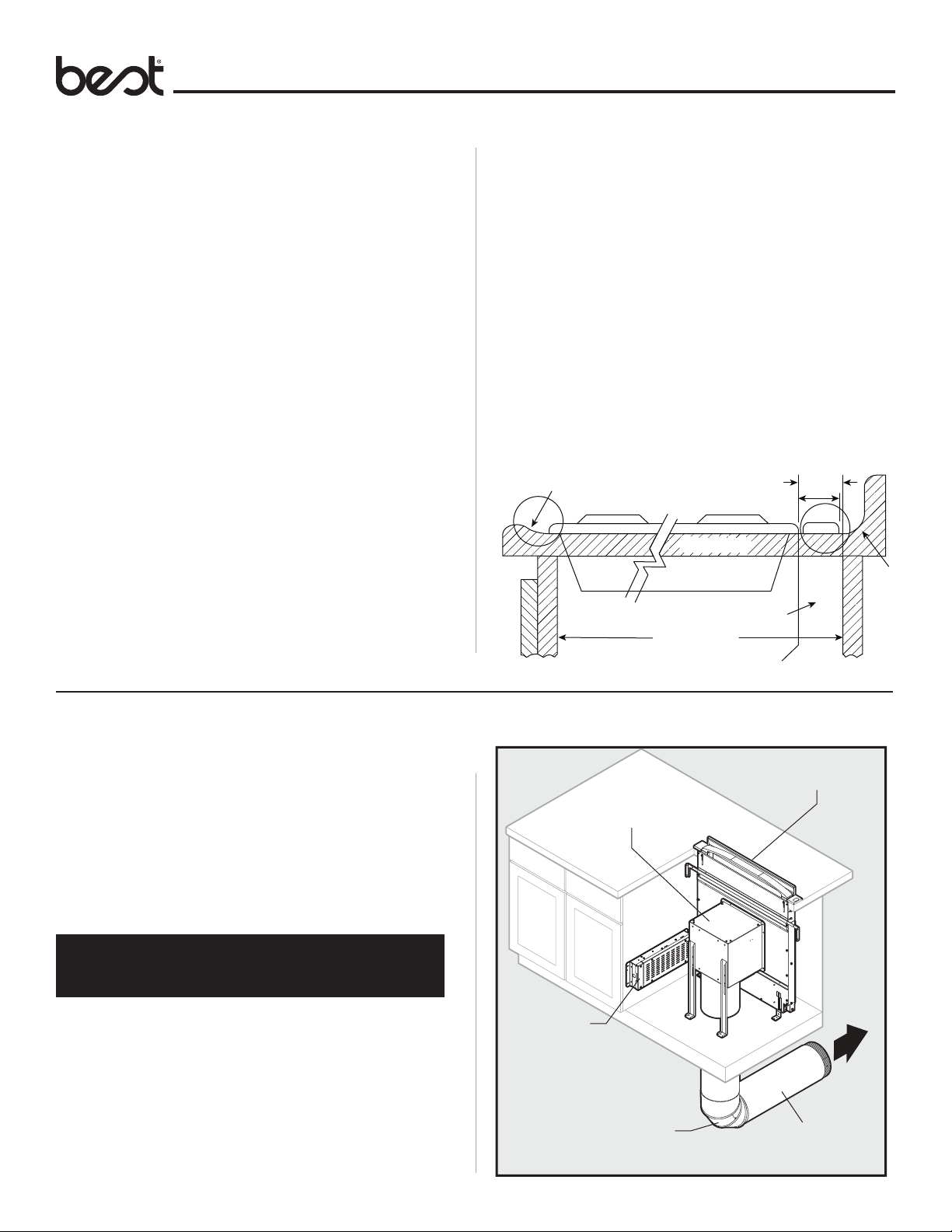
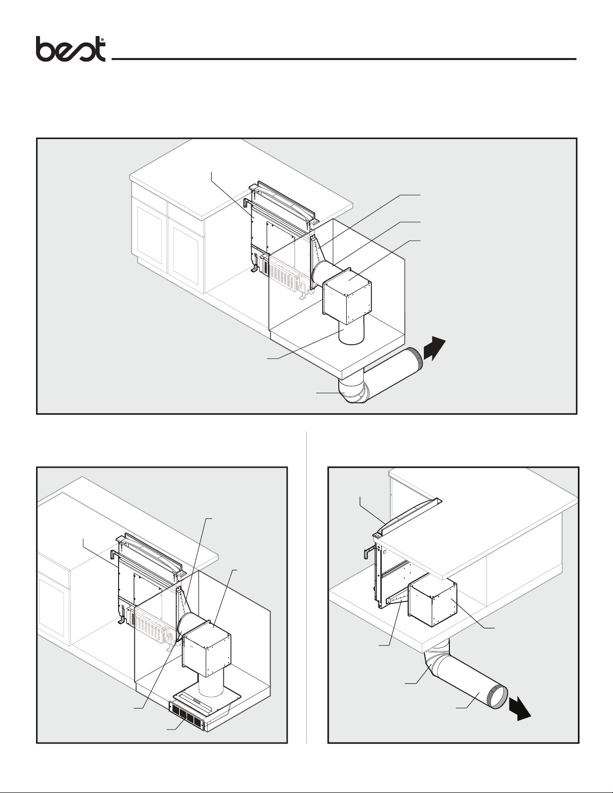
Front Exhaust with Flex Blower
PF6 (Flex Blower)
Wiring Box
8" Round Elbow
*To Model 643 (8" Round Wall Cap)
Downdraft
*
8" Straight Duct
5
Page 6
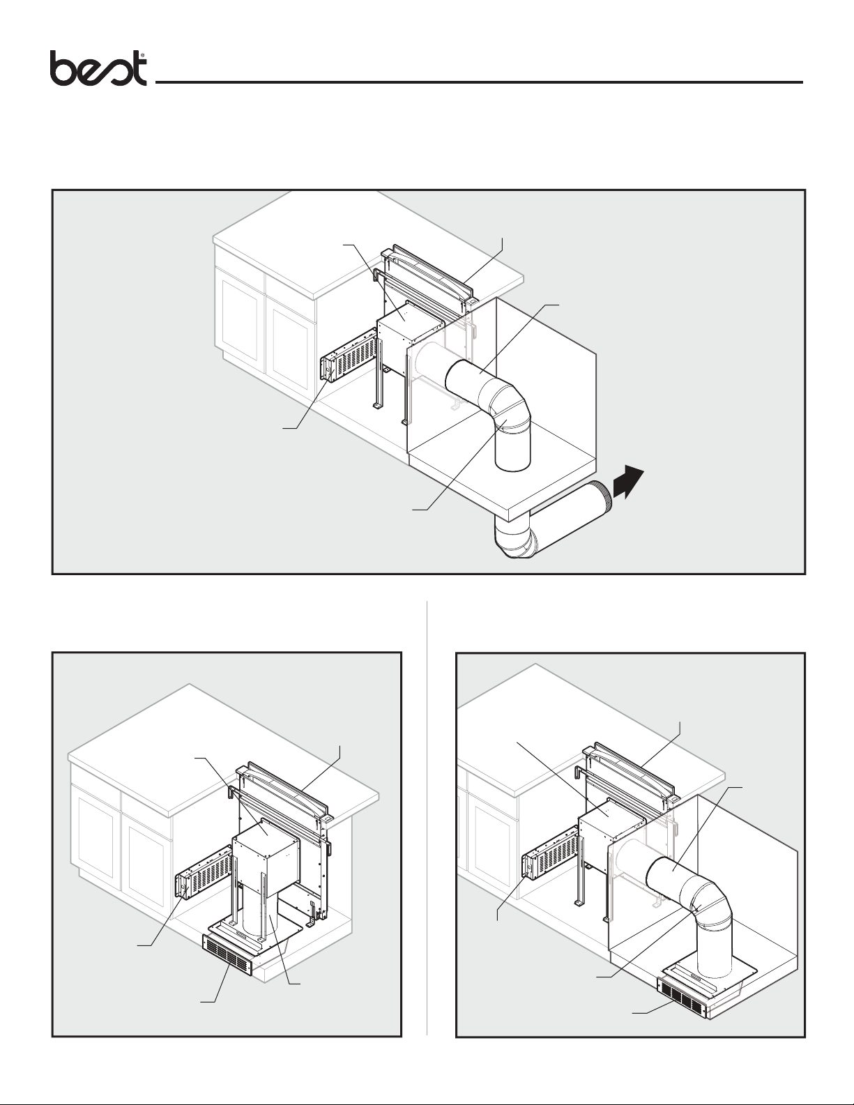
Ducting Confi gurations (continued)
Front Exhaust with Flex Blower (through cabinet)
PF6 (Flex Blower)
Wiring Box
Planning
Downdraft
8" Straight Duct
Front Exhaust with Flex Blower and
Recirculating Kit
Downdraft
PF6 (Flex Blower)
*
8" Round Elbow
*To Model 643 (8" Round Wall Cap)
Front Exhaust with Flex Blower (through
cabinet) and Recirculating Kit
Downdraft
PF6 (Flex Blower)
8" Straight
Duct
Wiring Box
ANKD (Recirculation Kit)
8" Straight Duct
Wiring Box
8" Round Elbow
ANKD (Recirculation Kit)
6
Page 7
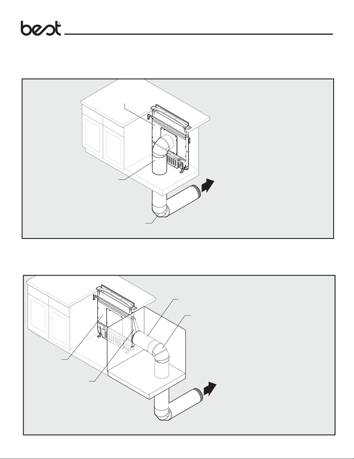
Ducting Confi gurations (continued)
Side Exhaust with Flex Blower
Downdraft
Planning
1-7/8" to 8"
Round Transition
8" Straight Duct
PF6 (Flex Blower)
8" Straight Duct
8" Round Elbow
*
*To Model 643 (8" Round Wall Cap)
Side Exhaust with Flex Blower and
Recirculating Kit Rear Exhaust with Flex Blower
Downdraft
1-7/8" to 8"
Downdraft
Round Transition
PF6
(Flex Blower)
1-7/8" to 8"
Round Transition
PF6 (Flex Blower)
8" Straight Duct
ANKD (Recirculation Kit)
8" Round Elbow
8" Straight Duct
*
*To Model 643 (8" Round Wall Cap)
7
Page 8
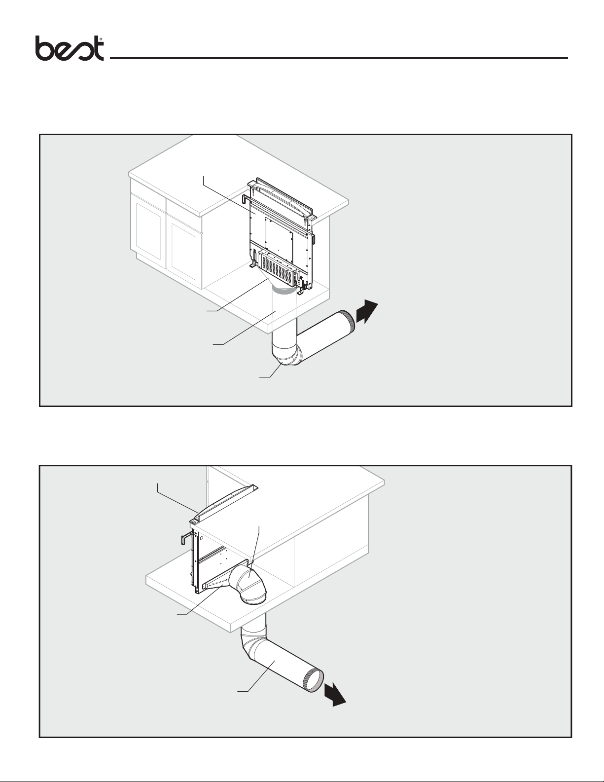
Ducting Confi gurations (continued)
Front Exhaust with Remote Blower
Downdraft
8
" or 10"
Straight Duct
8" or 10" Round Elbow
Note: Flex blowers require 8" ducting. External or in-line blowers require 10" ducting.
Planning
* To one of the following:
*
• Model PF6 (Flex Blower)
Model 643 (8" Round Wall cap)
• Model EB9 (900 cfm 10" Exterior Blower)
• Model ILB11 (10" Round In-Line Blower)
Model 441 (10" Round Wall Cap)
• Model EB12 (1200 cfm 10" Round Exterior Blower)
• Model EB15 (1500 cfm 10" Round Exterior Blower)
Side Exhaust with Remote Blower
8
" or 10"
Downdraft
1-7/8" to 8" or
10" Round Transition
Note: Flex blowers require 8" ducting. External or in-line blowers require 10" ducting.
Straight Duct
8" or 10" Round Elbow
* To one of the following:
• Model PF6 (Flex Blower)
*
Model 643 (8" Round Wall cap)
• Model EB9 (900 cfm 10" Exterior Blower)
• Model ILB11 (10" Round In-Line Blower)
Model 441 (10" Round Wall Cap)
• Model EB12 (1200 cfm 10" Round Exterior Blower)
• Model EB15 (1500 cfm 10" Round Exterior Blower)
8
Page 9
Ducting Confi gurations (continued)
Below Exhaust with Remote Blower
Downdraft
1-7/8" to 8" or
10" Round Transition
8
" or 10"
Straight Duct
8" or 10" Round Elbow
Note: Flex blowers require 8" ducting. External or in-line blowers require 10" ducting.
Planning
*
* To one of the following:
• Model PF6 (Flex Blower)
Model 643 (8" Round Wall cap)
• Model EB9 (900 cfm 10" Exterior Blower)
• Model ILB11 (10" Round In-Line Blower)
Model 441 (10" Round Wall Cap)
• Model EB12 (1200 cfm 10" Round Exterior Blower)
• Model EB15 (1500 cfm 10" Round Exterior Blower)
Rear Exhaust with Remote Blower
Downdraft
8" or 10" Round Elbow
1-7/8" to 8" or
10" Round Transition
8
" or 10"
Straight Duct
Note: Flex blowers require 8" ducting. External or in-line blowers require 10" ducting.
* To one of the following:
• Model PF6 (Flex Blower)
Model 643 (8" Round Wall cap)
• Model EB9 (900 cfm 10" Exterior Blower)
• Model ILB11 (10" Round In-Line Blower)
*
Model 441 (10" Round Wall Cap)
• Model EB12 (1200 cfm 10" Round Exterior Blower)
• Model EB15 (1500 cfm 10" Round Exterior Blower)
9
Page 10
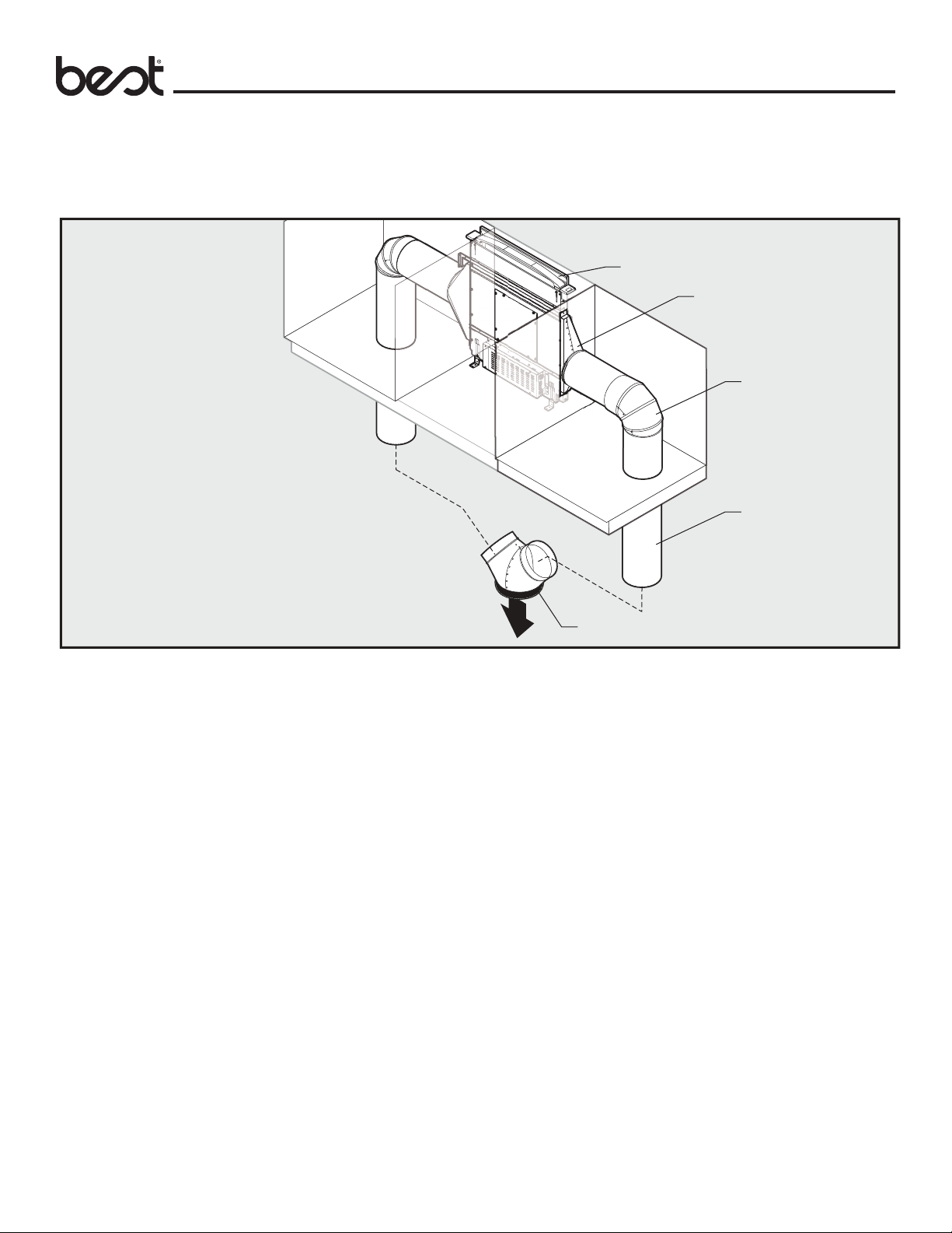
Ducting Confi gurations (continued)
Dual Duct Side Exhaust with Remote Blower
Planning
Downdraft
1-7/8" to 8"
Round Transition
8" Round Elbow
8" Straight Duct
* To one of the following:
• Model EB9 (900 cfm 10" Exterior Blower)
• Model ILB11 (10" Round In-Line Blower)
Model 441 (10" Round Wall Cap)
• Model EB12 (1200 cfm 10" Round Exterior Blower)
• Model EB15 (1500 cfm 10" Round Exterior Blower)
*
Dual 8" Round to 10" Round Transition
10
Page 11
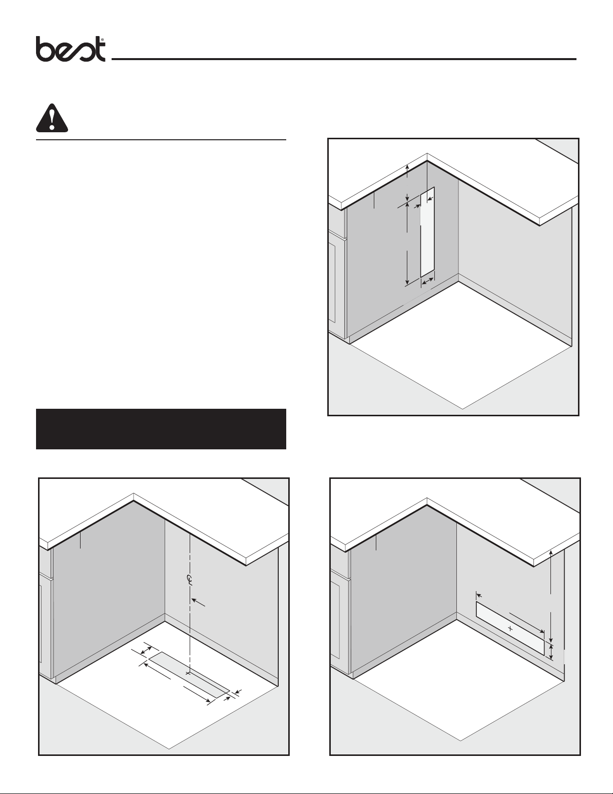
Cabinet Cutouts
CAUTION
BEFORE CUTTING HOLE IN CABINET FOR DUCTWORK,
check for interference with fl oor joists, wall studs,
electrical wiring, or plumbing.
Use the dimensions in illustrations to help plan how and where to
provide duct access through your cabinet. A 1-7/8" x 19" rectangular
duct can be used through left, right, fl oor and back of cabinet. Also,
8" round or 10” round can also be used through cabinet fl oor.
For left, right, or rear exhaust: Allow at least 18" for transition and
elbow or blower.
For left / right exhaust: a 30" deep cabinet is recommended to
align properly with fl ex blower. Flex blower can be mounted to rear
cabinet wall or to a platform / frame (not provided) on the base of
the cabinet fl oor. (See fl ex blower instructions).
Side Ducting Cutout
5-7/8"
5-7/8"
(14.9 cm)
(14.9 cm)
(5.1 cm)
"
21"
21
(53.3 cm)
(53.3 cm)
(10.2 cm)
2"
4"
Appliance
Cutout
Planning
Note: Flex blower can only attach to the front of the downdraft.
Cabinet depths of 24" to 30" are required - depending on the
type of cooking appliance.
If using a Recirculating Kit, see “Plan the installation”
section of the installation instructions packaged with the kit.
Below Ducting Cutout
Appliance
Cutout
Center line of downdraft
(10.2 cm)
(10.2 cm)
4"
4"
Rear Ducting Cutout
Appliance
Cutout
21"
21"
(53.3 cm)
(53.3 cm)
24-3/4"
24-3/4"
(62.9 cm)
(62.9 cm)
(53.3 cm)
(53.3 cm)
21"
21"
1-1/8"
1-1/8"
(2.9 cm)
(2.9 cm)
4"
(10.2 cm)
11
Page 12
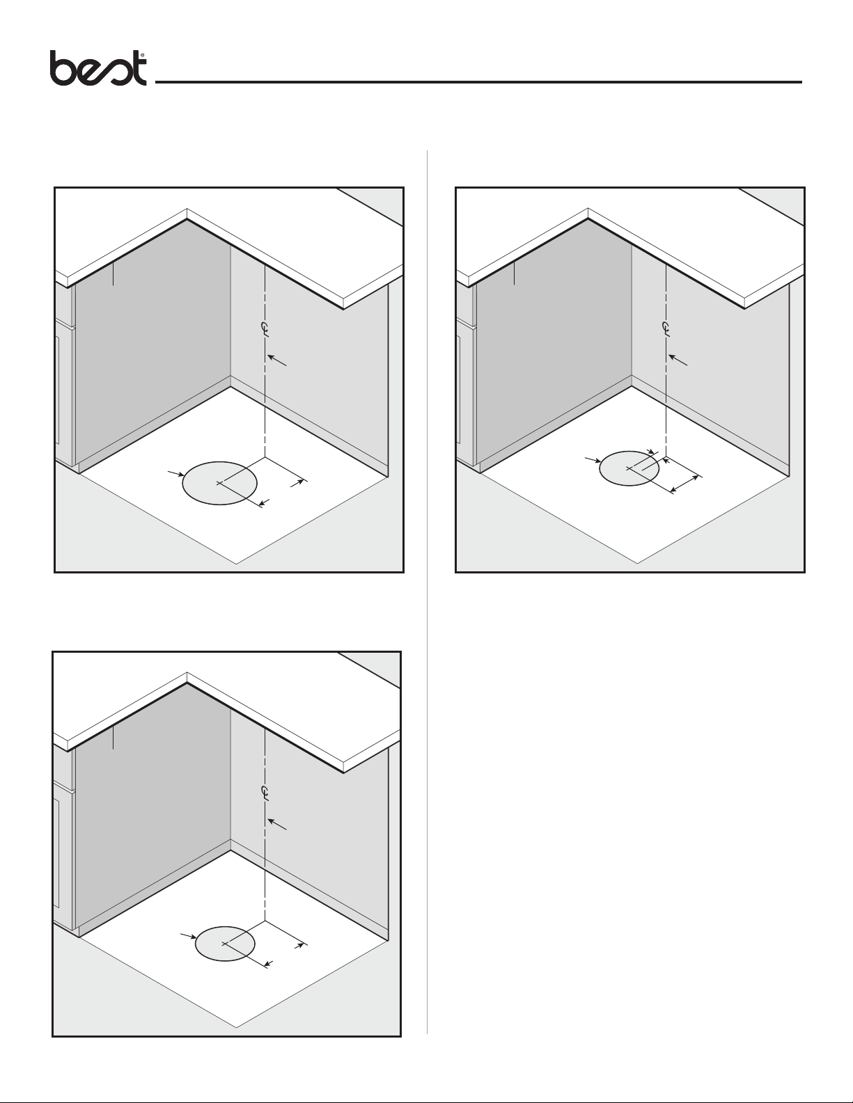
Cabinet Cutouts (continued)
Planning
Flex Blower Ducting Cutout10" Exterior or In-line Blower Ducting Cutout
Appliance
Cutout
Center line of downdraft
Ø10"
(25.4 cm)
8-5/8
8-5/8
(21.9 cm)
(21.9 cm)
"
"
Dimensions based off of Model 418 - 10" round elbow
Flex Blower Ducting – Remote Location Cutout
Appliance
Cutout
Ø8"
(20.3 cm)
1-1/2"
(3.8 cm)
Center line of downdraft
5-5/8"
5-5/8"
(14.3 cm)
(14.3 cm)
Appliance
Cutout
Center line of downdraft
Ø8"
(20.3 cm)
7-5/8"
7-5/8"
(19.4 cm)
(19.4 cm)
Dimensions based off of Model 432 - 8" round elbow
12
Page 13

Electrical Outlet Location
Planning
Flex Blower only
CAUTION
All electrical wiring should be done by a qualifi ed
person(s) in accordance with all applicable codes
and standards.
• This downdraft blower using the Flex Blower (purchase
separately) draws 3.0 Amps and requires a
120 VAC, 60 Hz circuit.
• The unit has a 30 in. long power cord with a 3-pronged plug.
Plan to provide a grounded outlet in a location which will
allow the unit’s power cord to reach.
• Install electrical box according to local codes.
Note: The unit electrical panel can be installed in remote
location (as show below) to help reach the outlet (see page 16).
Exterior or In-Line Blower only
CAUTION
All electrical wiring should be done by a qualifi ed
person(s) in accordance with all applicable codes
and standards.
• If using a remote blower (purchase separately), the
system draws 6.0 Amps (max.) and requires a 120 VAC,
60 Hz circuit.
• The unit has a 30 in. long power cord with a 3-pronged plug.
Plan to provide a grounded outlet in a location which will allow
the unit’s power cord to reach.
• Install electrical box according to local codes.
Note: The unit electrical panel can be installed in remote
location (as shown below) to help reach the outlet (see page 16).
Mount a standard wiring box, with 3-pronged receptacle, within reach
of downdraft’s power cord. Run appropriate power cable and connect it
to receptacle.
Mount a standard wiring box, with 3-pronged receptacle, within reach
of downdraft’s power cord. Run appropriate power cable and connect it
to receptacle.
13
Page 14

Preparing the Downdraft
Downdraft Preparation
1
B
E
E
JA
Detach the upper support brackets (A, J) from the downdraft (B) by cutting
off the tie wraps. Remove and set aside both support legs (E) from sides of
the downdraft (one leg per side).
Note: Discard the retaining screws, but KEEP THE NUTS.
2
Side, Below or Rear Rectangular Ducting
1
B
Install an adapter and a rectangular ductwork to downdraft (B).
2
Side, Below or Rear Round Ducting
B
F
Remove the bundle of 3 dischage covers (F) from the bottom of the
donwdraft (B).
3
B
B
1
Install 1-7/8" x 19” to 8" or 10" round transition to downdraft (B).
F
F
Cover the discharge openings that won’t be used for ducting.
Note: Use the nuts removed in step 1 for side discharge covers.
14
Page 15

Front Ducting
1
B
G
Remove front panel cover (G) from downdraft (B).
Preparing the Downdraft
2a
B
Install 8" or 10" remote discharge plate to downdraft (B).
2b
B
Install the fl ex blower to downdraft (B).
Note: Flex blower can be installed with duct to left, right or downward.
15
Page 16

Preparing the Downdraft
Electrical Panel in Remote Location
1
B
H
Remove electrical panel (H) from downdraft (B).
Note: Option for most installations. Required for ex blower installations when
discharge is down.
2
Final Assembly
3
B
E
E
Attach previously removed lower support legs (E) to downdraft (B) using one
nut for each leg.
4
Install electrical panel
in remote location.
A
B
I
Slide upper support brackets (A, I) into side channels of downdraft (B).
Flex Blower Only
5
If using fl ex blower, attach blower support legs with supplied screws.
16
Page 17

Cutting Countertop Opening
Installation
6a
6b
Cooktop
Cooktop with Oven
6d
7
Range
6c
Rangetop
Place appliance.
Note: Cook top shown.
Center line
8
Center template against the back fl ange of cooktop and mark downdraft
opening.
17
of back flange
Page 18

Installation
Cutting Counter Top Opening (continued)
9
Remove cook top/appliance and cut opening.
Install Housing into Cabinet
10
Install Housing into Cabinet
12
1
E
1
AA
2
Attach support legs (E) to bottom of cabinet with two screws (AA) per
leg. Tighten hex screws. Note: If cabinet bottom is removed, use wood
blocks as spacers between oor and support legs.
13
Set housing into cabinet.
11
A
J
AA
2
Extend upper support brackets (A and J) and attached to sides of cabinet
with two screws (AA) per bracket.
Flex Blower Only
14
1
1
2
3
4
Level housing.
Note: Steps 11-15, right cabinet not shown for clarity.
2
Loosen four screws attaching blower support legs to fl ex blower. Extend
legs and secure to bottom of cabinet with one screw through each
18
bracket. Re-tighten four blower screws.
Page 19

Installation
1
1
C
Installing Finish Trim
15
B
1
D
2
CAUTION
Only connect or disconnect UP BUTTON CABLE
with main power off for at least 60 seconds.
Insert wiring harness from right upper button (D) into opening in side of
downdraft (B). Insert upper button (D) wiring harness into receptacle at
lower right side of downdraft (B).
Installing Finish Trim (continued)
17
C
2
2
Retaining
Retaining
Washer
Washer
Place retaining washer on left trim cap (C). Insert hinge pin into slot of the
fl ip door. Position left trim cap and fl ip door. Align trim caps and complete
assembly by hand tightening trim cap screws.
Note: Make sure trim sits at on countertop surface, is ush with top door,
and has 1/16” GAP between trim and top door.
3
TOP VIEW
1/16" Gap1/16" Gap
C
Washer
DoorTrim
Flush
Installing Ductwork
CAUTION
16
TOP VIEW
Washer
D
Retaining
Retaining
Washer
Washer
4
2
Door Trim
3
Flush
1/16" Gap1/16" Gap
D
D
Position right trim cap (D) and start screw. Do not fully tighten screw.
Place retaining washer on right trim cap. Insert hinge pin into slot of the
fl ip door.
Note: Make sure trim: sits at on countertop surface, is ush with top door,
has 1/16” GAP between trim and top door, and wiring is not pinched.
BEFORE CUTTING HOLE IN CABINET FOR
DUCTWORK, check for interference with fl oor
joists, wall studs, electrical wiring, or plumbing.
• Refer to Ductwork Confi gurations in the Planning section of this
document.
• Cut hole in cabinet as well as holes in wall or fl oor as necessary.
• Mount the roof or wall cap and work back towards the cabinet,
attaching all ductwork, elbows and transitions as previously
planned. Tape all ductwork connections to make them secure and
air tight.
• Connect ductwork (and transition, if required) to downdraft.
19
Page 20

Flex Blower only
CAUTION
All electrical wiring should be done by a qualifi ed
person(s) in accordance with all applicable codes
and standards.
18a
Electrical Wiring Installation
20a
Plug electrical panel cable into lower receptacle on side of downdraft.
H
Remove electrical panel (H) cover and route blower wire into wiring box.
19a
Connect blower wires to wires in electrical panel: White to White, Blue to
Blue, Red to Gray, Orange to Orange and Black to Black. Connect Green
wire to ground screw. Replace electrical panel cover.
Green (ground)Green (ground)
White White (neutral)
White White (neutral)
Blue Blue (low 1)
Blue Blue (low 1)
Red Gray (med 2)
Red Gray (med 2)
Orange Orange (med- high)
Orange Orange (med- high)
Black Black (high 4)
Black Black (high 4)
21a
Plug downdraft’s power cord into outlet.
Note: Make sure that power cord is routed away from the heat
generated by the cooktop.
20
Page 21

Exterior or In-Line Blower only
CAUTION
All electrical wiring should be done by a qualifi ed
person(s) in accordance with all applicable codes
and standards.
18b
From Exterior or
From Exterior or
In-Line Blower
In-Line Blower
Electrical Wiring Installation
20b
Plug electrical panel cable into lower receptacle as shown.
21b
H
Remove wiring box (H) cover and route blower wire into wiring box.
19b
Connect blower wires to wires in wiring box: White to White, Black to Black
and Green wire to ground screw. Replace wiring box cover.
Note: Ensure that Blue, Gray and Orange wires are capped off but not connected.
Green (ground)Green (ground)
White White (neutral)
White White (neutral)
Blue
Blue
Gray
Gray
Orange
Orange
Black Black (high 4)
Black Black (high 4)
Plug downdraft’s power cord into outlet.
Note: Make sure that power cord is routed away from the heat generated
by the cooktop.
21
Page 22

Appliance Installation/Operation
Install Cooking Appliance
1. Align the cooking appliance with downdraft and fasten appliance
in place following appliance instructions.
Control Panel and Up Button
2-Level Task Light
• Press once for LOW setting. Top of icon will illuminate.
• Press 2x for HIGH setting. Top and bottom of icon will
illuminate.
• Press 3x to turn task light OFF.
4-Speed Fan Speed Control
• Press once for LOW setting. Top-right quadrant of icon will
illuminate.
• Press 2x for MEDIUM LOW setting. Top-right and bottom-right
quadrants of icon will illuminate.
• Press 3x for MEDIUM HIGH setting. Top-right, bottom-right, and
bottom-left quadrants of icon will illuminate.
• Press 4x for HIGH setting. All quadrants of icon will illuminate.
• Press 5x to turn fan OFF.
10-Minute Delay Off
When fan is ON at any speed setting, press delay-off icon to start
10-minute timer. Fan and icon will shut off after 10 minutes.
To reset or deactivate delay-off, press icon again.
Note: Accurate alignment of cooking appliance and downdraft is
necessary to ensure that there is no interference when air vent is raised
and lowered. There should be a gap of 1/32" - 1/16 " between the back
of the cooktop and the front of the downdraft cover.
30-Hour Filter Clean Reminder
• After 30 hours of blower “ON” time, fi lter clean icon will blink
continuously.
• To reset, touch and hold icon for 2 or more seconds. Indicator
will turn off.
Down / Retract Chimney
• To retract chimney, touch down button. Any feature that is
active will shut off.
Up Button
• Touch up button on right trim to raise chimney. All functions will
return to their previous settings.
Heat Sentry
• When the operating temperature is too high, the fan speed will
increase to its highest setting to protect sensitive components.
The fan icon will blink and cannot be overridden until the
temperature reaches an acceptable level. The fan speed will
return to the previous setting and the icon will stop blinking.
2-Level Task Light
4-Speed Fan Speed Control
10-Minute Delay Off
30-Hour Filter Clean Reminder
Down / Retract Chimney
Up Button
22
Page 23

Cooking
WARNING
Use and Care
Always disconnect electric power
supply before cleaning and/or servicing unit.
Always turn the downdraft blower on before you begin cooking
to establish an air fl ow in the kitchen. Let the blower run for a few
minutes to clean the air after you turn the cooktop off. This will
keep the whole kitchen cleaner and brighter.
It is recommended to use the rear burners when cooking with tall
pots or when the cooking method will generate high amounts of
smoke or steam. The combination of using the rear burners and
operating the unit at high speed will increase the likelihood that
all the smoke and steam will be removed by the downdraft.
Cleaning
Ears
Tabs
Filter
Filter
CAUTION
Failure to engage tabs properly may cause chimney
to jam and fail to raise up.
To clean inside chimney:
Lift FRONT PANEL up and out and take out the GREASE FILTERS.
Use a mild detergent. DO NOT USE ABRASIVE CLOTH, STEEL WOOL
PADS, OR SCOURING POWDERS. Replace fi lters and front panel
before using downdraft.
Be sure to engage TABS on front panel behind EARS as shown.
Servicing
It may be necessary to remove the downdraft blower system from
the cabinet in order to service components such as the blower
motor or air vent mechanism.
Disconnect power to the cooktop and remove it fi rst. Reverse the
steps under “INSTALL HOUSING INTO CABINET” to remove the
downdraft from the cabinet.
Front Panel
CAUTION
Failure to engage tabs properly may cause chimney
to jam and fail to raise up.
To Clean grease fi lters:
Lift FRONT PANEL up and out and take out the GREASE FILTERS.
The grease fi lters should be cleaned frequently. Use a warm
dishwashing detergent solution. Grease fi lters are dishwasher safe.
Clean all-metal fi lters in the dishwasher using a non-phosphate
detergent. Discoloration of the fi lters may occur if using phosphate
detergents, or as a result of local water conditions - but this
will not affect fi lter performance. This discoloration is not covered
by the warranty. To minimize or prevent discoloration, hand wash
fi lters using a mild detergent. Replace fi lters and front panel before
using downdraft.
Be sure to engage TABS on front panel behind EARS as shown.
23
Page 24

Optional Accessories
Optional Accessories
Accessory Description
MODELS
ACRD
ACRDBLS
MODELS
ATSKD30
ATSKD36
ATSKD48
MODELS
MD6T
MD8T
MD10T
REMOTE UP/DOWN CONTROL
Use when you cannot reach the UP/
DOWN Button on the downdraft chimney.
Can be located on counter top, face of
cabinetry or on the side cabinet of an
island. Cut-out size: 2 1/4" H x 2" W.
Cannot be used where remote control
will interfere with cooking, where hot
pans could be set, or where hot liquids
could be spilled on the control.
(Remote wiring connects with 6-pin
connection)
GAS COOKTOP SEAL KIT
Recommended for use with all gas
cooktops. Includes trim bracket and trim
seal.
30", 36" & 48" widths.
MAKE-UP AIR DAMPER
Use to provide make-up air (when called
for) to keep the home comfortable by
allowing the downdraft to operate at
optimum levels.
Directwire design works with select
BEST® downdrafts to balance indoor air
pressure by providing interlocked makeup air; damper opens automatically
when the range hood is activated.
8" & 10" round diameters.
Connects to 2 CONTACTS on
ELECTRICAL PANEL.
MAKE-UP
AIR DAMPER
CONTACTS
Accessory Description
MODEL AEWD5 EXTENSION CABLE - 5-FT.
Use where electrical panel is remotely
mounted. Extends electrical panel cable
an additional 5 feet.
MODEL ANKD
MODEL AFCD RECIRCULATION FILTER REPLACEMENT
MODEL AVDKD8
MODEL AVDKD10
NON-DUCT RECIRCULATING KIT
Use where ducting is not feasible or
available. Mount to toe kick or base of
a cabinet and attach directly to Model
PF6 Flex Blower using 8" round duct. Kit
can be rotated so that the exhaust is not
directly at your feet. Includes
recirculation fi lter and decorative
cover plate.
Replacement fi lter for ANKD Non-Duct
Recirculating Kit. Use to effectively
capture cooking contaminants.
1-7/8" X 19” TO 8" ROUND
TRANSITION
Rectangular to 8" round transition for
left, right, or rear exhaust - using Model
PF6 Flex Blower. Can be attached to
downdraft unit or rectangular duct
(AEDD2). Includes S-clips for easy,
secure attachment.
1-7/8" X 19" TO 10" ROUND
TRANSITION
Rectangular to 10" round transition for
left, right, or rear exhaust - using
external blower. Can be attached to
downdraft unit or rectangular duct
(AEDD2).
MODELS
ATKD30SB
ATKD36SB
ATKD48SB
RANGE TRIM KIT
Use with free-standing range - where a
gap is present between back of range
and downdraft.
30", 36" & 48" widths.
MODEL AVDKD219
24
RECTANGULAR ADAPTER FOR
1-7/8" X 19"
Use to connect 1-7/8" x 19" rectangular
duct directly to downdraft when using
side, below or rear exhaust.
Page 25

Optional Accessories (continued)
Optional Accessories
Accessory Description
MODELS
ATTD1
ATTD1BLS
MODEL ACVPD8
MODEL ACVPD10 FRONT PANEL ROUGH-IN PLATE -
END CAP TRIM EXTENSION +1"
WIDTH - LH & RH
Use left and right to increase the overall
trim width by 1".
FRONT PANEL ROUGH-IN PLATE 8" ROUND
Use where 8" round duct or elbow
attaches to front of airbox (Model PF6
remote blower installation).
10" ROUND
Use where 10" round duct or elbow
attaches to front of airbox (exterior or
in-line blower installation).
Accessory Description
MODEL 408 - 8" RD.
MODEL 410 - 10" RD.
MODEL AEDD2
STRAIGHT ROUND DUCT - 2-FT.
Galvanized steel construction.
RECTANGULAR DUCT - 2-FT.
SECTIONS (1-7/8" X 19")
Galvanized steel construction.
MODEL 432 - 8" RD.
MODEL 418 - 10" RD.
90˚ DUCTWORK ELBOW
Adjustable from straight to 90˚.
Galvanized steel construction.
MODEL AVDKD8810
TRANSITION “Y” (2) - 8" ROUND TO
(1) - 10" ROUND
Galvanized steel construction.
25
Page 26

Internal Blower (PF6) – Front Mounted to Downdraft
MODEL PF6
Flex Blower (sold separately)
(“Down” discharge shown. Blower
can also be rotated for “Left” or
“Right” discharge.)
MODEL 408 *
8-inch Round
Straight Duct
Electrical Panel
(Mount in remote location)
Appendix A
MODEL 643 *
8-inch Round
Wall Cap
MODEL 432 *
8-inch Round Elbow
MODEL AEWD5
5-foot Extension
Cable (sold separately)
(Only required if electrical panel
is more than 2-feet away from
downdraft. Use up to 2 extension
cables connected together.)
MODEL ANKD
Non-Duct Recirculation Kit with
Kickspace Grille (sold separately)
(Only required for non-duct
applications. “Front” discharge
shown. Kit can also be rotated for
“Left” , “Right” or “Rear” discharge.)
MODEL 408 *
8-inch Round
Straight Duct
* As required - sold separately.
26
Page 27

Internal Blower (PF6) – Remote Mounted – Front Outlet
MODEL ACVPD8
8-inch Round Front
Rough-in Plate
(sold separately)
MODEL 432 *
8-inch Round Elbow
Electrical Panel
(Can be mounted
in remote location)
MODEL 408 *
8-inch Round
Straight Duct
Appendix B
MODEL AEWD5
5-foot Extension Cable
(sold separately)
(Only required if electrical panel
is mounted in a remote location more than 2-feet away from
downdraft. Use up to 2 extension
cables connected together.)
* As required - sold separately
MODEL PF6
Flex Blower (sold separately)
MODEL 408 *
8-inch Round
Straight Duct
MODEL 643 *
8-inch Round
Wall Cap
27
Page 28

Internal Blower (Pf6) – Remote Mounted – Side Outlet
MODEL AVDKD219 *
1-7/8-inch x 19-inch
Rectangular Adapter
(sold separately)
(Only required to
extend duct along
back of cabinet.)
Electrical Panel
(Can be mounted in
remote location.)
MODEL AEDD2 *
1-7/8-inch x 19-inch
Rectangular Duct
(sold separately)
(Only required to
extend duct along
back of cabinet.)
MODEL AEWD5
5-foot Extension Cable
(sold separately)
(Only required if
electrical panel is mounted
in a remote location - more
than 2-feet away from downdraft.
Use up to 2 extension cables
connected together.)
MODEL AVDKD8
1-7/8-inch x 19-inch
to 8-inch Round Transition
(sold separately)
MODEL 432 *
8-inch Round
Elbow
MODEL 408 *
8-inch Round
Straight Duct
Appendix C
MODEL PF6
Flex Blower
(sold separately)
(Mounted in
adjacent cabinet)
MODEL 408 *
8-inch Round
Straight Duct
MODEL ANKD
Non-Duct Recirculation Kit
with Kickspace Grille
(sold separately)
(Only required for non-duct
applications. “Front” discharge
shown. Kit can also be rotated
for “Left” , “Right” or “Rear” discharge.)
MODEL 643 *
8-inch Round
Wall Cap
MODEL 408 *
8-inch Round
Straight Duct
28
MODEL PF6
Flex Blower
(sold separately)
(Mounted in
adjacent cabinet)
* As required - sold separately.
Page 29

Internal Blower (Pf6) – Remote Mounted – Rear Outlet
MODEL AEDD2 *
1-7/8-inch x 19-inch
Rectangular Duct
(sold separately)
MODEL AVDKD219 *
1-7/8-inch x 19-inch
Rectangular Adapter
(sold separately)
Appendix D
MODEL AVDKD8
1-7/8-inch x 19-inch
to 8-inch Round Transition
(sold separately)
MODEL PF6
Flex Blower
(sold separately)
(Mounted in
adjacent cabinet)
MODEL 643 *
8-inch Round
Wall Cap
MODEL 408 *
8-inch Round
Straight Duct
MODEL 432 *
8-inch Round
Elbow
MODEL 408 *
8-inch Round
Straight Duct
MODEL PF6
Flex Blower
(sold separately)
(Mounted in
remote location)
MODEL 408 *
8-inch Round
Straight Duct
MODEL ANKD
Non-Duct Recirculation Kit
with kickspace grille
(sold separately)
(Only required for non-duct
applications. “Front” discharge
shown. Kit can also be rotated
for “Left” , “Right” or “Rear” discharge.)
* As required - sold separately.
29
Page 30

)
Internal Blower (Pf6) – Remote Mounted – Below Outlet
Electrical Panel
(Can be mounted in
remote location.)
MODEL AVDKD8
1-7/8-inch x 19-inch
to 8-inch Round Transition
(sold separately)
Appendix E
MODEL AEWD5
5-foot Extension Cable
(sold separately)
(Only required if
electrical panel is mounted
in a remote location - more
than 2-feet away from downdraft.
Use up to 2 extension cables
connected together.)
MODEL 643 *
8-inch Round
Wall Cap
MODEL 408 *
8-inch Round
Straight Duct
MODEL PF6
Flex Blower
MODEL 408 *
8-inch Round
Straight Duct
* As required - sold separately.
(sold separately)
(Mounted in
adjacent cabinet)
MODEL 432 *
8-inch Round Elbow
MODEL PF6
Flex Blower
(sold separately)
(Mounted in
adjacent cabinet)
MODEL 408 *
8-inch Round
Straight Duct
MODEL ANKD
Non-Duct Recirculation Kit
with Kickspace Grille
(sold separately)
(Only required for non-duct
applications. “Front” discharge
shown. Kit can also be rotated
for “Left” , “Right” or “Rear” discharge.
30
Page 31

Exterior or In-Line Blower – Front Outlet
Appendix F
MODEL AEWD5
5-foot Extension Cable
(sold separately)
(Only required if
Electrical Panel is mounted
in a remote location - more
than 2-feet away from downdraft.
Use up to 2 Extension Cables
connected together.)
(Standard 120 VAC
wiring rated for 6 A
minimum - sold separately.)
MODEL EB9 **
900 cfm
10-inch Round
Exterior Blower
MODEL
10-inch Round
Front Rough-in Plate
(sold separately)
Electrical Panel
(Can be mounted in
remote location.)
ACVPD10
MODEL 418 *
10-inch Round Elbow
MODEL 410 *
10-inch Round Straight Duct
MODEL 418 *
10-inch Round Elbow
MODEL 441 *
10-inch Round
Wall Cap
MODEL 410 *
10-inch Round
Straight Duct
MODEL ILB11 **
1100 cfm
10-inch Round
In-Line Blower
MODEL EB12 **
1200 cfm
10-inch Round
Exterior Blower
31
-- OR --
* As required - sold separately.
** Choose 1 exterior or in-line
blower - sold separately.
MODEL EB15 **
1500 cfm
10-inch Round
Exterior Blower
Page 32

Exterior or In-Line Blower – Side or Rear Outlet
MODEL AVDKD219 *
1-7/8-inch x 19-inch
Rectangular Adapter
MODEL AEWD5
5-foot Extension Cable
(sold separately)
(Only required if
Electrical Panel is mounted
in a remote location - more
than 2-feet away from downdraft.
Use up to 2 extension cables
connected together.)
(sold separately)
(Only required to extend
duct along back of cabinet)
MODEL AEDD2 *
1-7/8-inch x 19-inch
Rectangular Duct
(sold separately)
(Only required to
extend duct along
back of cabinet.)
Appendix G
MODEL AVDKD10
1-7/8-inch x 19-inch
to 10-inch Round Transition
(sold separately)
MODEL 418 *
10-inch Round Elbow
Electrical Panel
(Can be mounted in
remote location)
MODEL EB9 **
900 cfm
10-inch Round
Exterior Blower
MODEL 441 *
10-inch Round
Wall Cap
(Standard 120 VAC
wiring rated for 6A
minimum - sold separately)
MODEL 410 *
10-inch Round
Straight Duct
MODEL ILB11 **
1100 cfm
10-inch Round
In-Line Blower
MODEL EB12 **
1200 cfm
10-inch Round
Exterior Blower
-- OR --
MODEL 410 *
10-inch Round Straight Duct
MODEL 418 *
10-inch Round Elbow
* As required - sold separately
** Choose 1 exterior or in-line
blower - sold separately.
MODEL EB15 **
1500 cfm
10-inch Round
Exterior Blower
32
Page 33

Exterior or In-Line Blower – Below Outlet
Electrical Panel
(Can be mounted in
remote location.)
Appendix H
MODEL AEWD5
5-foot Extension Cable
(sold separately)
(Only required if
electrical panel is mounted
in a remote location - more
than 2-feet away from downdraft.
Use up to 2 extension cables
connected together.)
MODEL AVDKD10
1-7/8-inch x 19-inch
to 10-inch Round Transition
(sold separately)
MODEL EB9 **
900 cfm
10-inch Round
Exterior Blower
MODEL 441 *
10-inch Round
Wall Cap
(Standard 120 VAC
wiring rated for 6 A
minimum - sold separately.)
MODEL 410 *
10-inch Round
Straight Duct
MODEL ILB11 **
1100 cfm
10-inch Round
In-Line Blower
MODEL EB12 **
1200 cfm
10-inch Round
Exterior Blower
-- OR --
MODEL 410 *
10-inch Round Straight Duct
MODEL 418 *
10-inch Round Elbow
* As required - sold separately.
** Choose 1 exterior or in-line
blower - sold separately.
MODEL EB15 **
1500 cfm
10-inch Round
Exterior Blower
33
Page 34

Exterior or In-Line Blower – Dual Duct – Side Outlets
Appendix I
MODEL AEWD5
5-foot Extension Cable
(sold separately)
(Only required if electrical
panel is mounted in a remote
location - more than 2-feet
away from downdraft. Use
up to 2 extension cables
connected together.)
(Standard 120 VAC wiring rated
for 6A minimum - sold separately)
MODEL AVDKD219 *
1-7/8-inch x 19-inch
Rectangular Adapter
(sold separately)
(Only required to extend
duct along back of cabinet)
Electrical Panel
(Can be mounted in
remote location)
MODEL AEDD2 *
1-7/8-inch x 19-inch
Rectangular Duct
(sold separately)
(Only required to
extend duct along
back of cabinet)
MODEL AVDKD8
1-7/8-inch x 19-inch
to 8-inch Round Transition
(sold separately)
MODEL 423 *
8-inch Round Elbow
MODEL 408 *
8-inch Round Straight Duct
MODEL EB9 **
900 cfm
10-inch Round
Exterior Blower
MODEL 441 *
10-inch Round
Wall Cap
MODEL 410 *
10-inch Round
Straight Duct
MODEL ILB11 **
1100 cfm
10-inch Round
In-Line Blower
MODEL EB12 **
1200 cfm
10-inch Round
Exterior Blower
-- OR --
MODEL ATKD8810
Dual 8-inch Round to 10-inch
Round Transition (sold separately)
MODEL 418 *
10-inch Round Elbow
* As required - sold separately.
** Choose 1 exterior or in-line
blower - sold separately
MODEL EB15 **
1500 cfm
10-inch Round
Exterior Blower
34
Page 35

FIVE-YEAR LIMITED WARRANTY FOR BEST® PRODUCTS
Warranty
Limited Warranty
Warranty Period and Exclusions: Broan-NuTone, LLC (the “Company”)
warrants to the consumer purchaser of its product (“you”) that the product (the
“Product”) will be free from material defects in the materials or its workmanship
for a period of fi ve (5) years from the date of original purchase (or such longer
period as may be required by applicable law) or a period of two (2) years from
the date of service for any labor provided on the Product.
The limited warranty period for any replacement parts provided by the Company
and for any Products repaired or replaced under this limited warranty shall be
the remainder of the original warranty period (or such longer period as may be
required by applicable law).
THIS WARRANTY DOES NOT EXTEND TO FLUORESCENT LAMP STARTERS,
TUBES AND BULBS, FUSES, FILTERS, DUCTS, ROOF CAPS, WALL CAPS
AND OTHER ACCESSORIES FOR DUCTING. This warranty does not cover (a)
normal maintenance and service, (b) normal wear and tear, (c) any Products or
parts which have been subject to misuse, abuse, abnormal usage, negligence,
accident, improper or insuffi cient maintenance, storage or repair (other than
repair by the Company), (d) damage caused by faulty installation, or installation
or use contrary to recommendations or instructions, (f) damage caused by
exposure to salt air, (g) damage in transit, (h) natural wear of fi nish, (i) Products
in commercial or nonresidential use, (j) damage caused by fi re, fl ood or other act
of God, or (k) Products with altered, defaced or removed serial numbers. This
warranty covers only Products sold to consumers in North America.
This warranty supersedes all prior warranties and, subject to applicable law, is
not transferable from the original consumer purchaser.
No Other Warranties: This Limited Warranty contains the Company’s sole
obligation and your sole remedy for defective Products. The foregoing warranties
are exclusive and in lieu of any other warranties and conditions, express or
implied. TO THE MAXIMUM EXTENT PERMITTED BY APPLICABLE LAW, THE
COMPANY DISCLAIMS AND EXCLUDES ALL OTHER EXPRESS WARRANTIES
AND CONDITIONS, AND DISCLAIMS AND EXCLUDES ALL WARRANTIES AND
CONDITIONS IMPLIED BY LAW, INCLUDING WITHOUT LIMITATION THOSE OF
MERCHANTABILITY AND FITNESS FOR A PARTICULAR PURPOSE. To the extent
that applicable law prohibits the exclusion of implied warranties or conditions,
the duration of any applicable implied warranty or condition is limited to the
period specifi ed for the express warranty above. Some jurisdictions (which may
include the Province of Quebec or specifi c US states) do not allow limitations on
how long an implied warranty lasts, so the above limitation may not apply to you.
Any oral or written description of the Product is for the sole purpose of identifying
it and shall not be construed as an express warranty.
Whenever possible, each provision of this Limited Warranty shall be interpreted
in such manner as to be effective and valid under applicable law, but if any
provision is held to be prohibited or invalid, such provision shall be ineffective only
to the extent of such prohibition or invalidity, without invalidating the remainder
of such provision or the other remaining provisions of the Limited Warranty.
Remedy: During the applicable limited warranty period, the Company will, at its
option, provide replacement parts for, or repair or replace, without charge, any
Product or part thereof, to the extent the Company fi nds it to be covered by and
in breach of this limited warranty under normal use and service. The Company
will ship the repaired or replaced Product or replacement parts to you at no
charge. You are responsible for all costs for removal, reinstallation and shipping,
insurance or other freight charges incurred in the shipment of the Product or
part to the Company. If you must send the Product or part to the Company, as
instructed by the Company, you must properly pack the Product or part—the
Company is not responsible for damage in transit. The Company reserves the
right to utilize reconditioned, refurbished, repaired or remanufactured Products
or parts in the warranty repair or replacement process. Such Products and parts
will be comparable in function and performance to an original Product or part
and warranted for the remainder of the original warranty period (or such longer
period as may be required by applicable law).
Company reserves the right, in its sole discretion, to refund the money actually
paid by you for the Product. If the Product or component is no longer available,
replacement may be made with a similar product of equal or greater value, at
Company’s sole discretion. This is your sole and exclusive remedy for breach of
this limited warranty.
Exclusion of Damages: THE COMPANY’S OBLIGATION TO PROVIDE
REPLACEMENT PARTS, OR REPAIR OR REPLACE, AT THE COMPANY’S
OPTION, SHALL BE YOUR SOLE AND EXCLUSIVE REMEDY UNDER THIS
LIMITED WARRANTY AND THE COMPANY’S SOLE AND EXCLUSIVE
OBLIGATION. THE COMPANY SHALL NOT BE LIABLE FOR INCIDENTAL,
INDIRECT, CONSEQUENTIAL OR SPECIAL DAMAGES ARISING OUT OF OR IN
CONNECTION WITH THE PRODUCT, ITS USE OR PERFORMANCE.
Some jurisdictions do not allow the exclusion or limitation of incidental or
consequential damages, so the above limitation or exclusion may not apply to you.
This warranty gives you specifi c legal rights, and you may also have other rights, which
vary from jurisdiction to jurisdiction. The disclaimers, exclusions, and limitations of
liability under this warranty will not apply to the extent prohibited by applicable law.
This warranty covers only replacement or repair of defective Products or parts
thereof at the Company’s main facility and does not include the cost of fi eld
service travel and living expenses.
Any assistance the Company provides to or procures for you outside the terms,
limitations or exclusions of this limited warranty will not constitute a waiver of
such terms, limitations or exclusions, nor will such assistance extend or revive
the warranty.
The Company will not reimburse you for any expenses incurred by you in
repairing or replacing any defective Product, except for those incurred with the
Company’s prior written permission.
How to Obtain Warranty Service: To qualify for warranty service, you must (a)
notify the Company at the address or telephone number stated below within
seven (7) days of discovering the covered defect, (b) give the model number
and part identifi cation and (c) describe the nature of any defect in the Product
or part. At the time of requesting warranty service, you must present evidence
of the original purchase date. If you cannot provide a copy of the original written
limited warranty, then the terms of the Company’s most current written limited
warranty for your particular product will control.
PRODUCT SPECIFICATIONS
All illustrations and specifi cations in this catalog are based on the latest product
information available at time of production. Broan-NuTone, LLC and BEST®
reserves the right to make changes at any time, without notice, in prices, colors,
materials, equipment, specifi cations and models, place of manufacture and to
discontinue models or equipment.
Best
Broan-NuTone, LLC- 926 W. State Street, Hartford, WI 53207
1-800-637-1453
Best®, 550 Lemire Blvd., Drummondville, QC, Canada (1-866-737-7770)
www.bestrangehoods.com
35
Page 36

Parts
Service Parts
Stainless Steel Models
J
F
H
G
I
E
C
D
B
U
T
S
J
R
K
K
L
K
Key 30" 36" 48"
No. Width Width Width Description
1 S97021277-001 S97021277-002 S97021277-004 Top Cap Ass’y
Best
2 S97020367 S97020367 S97020367 Felt
3 S97021274 S97021274 S97021274 Door Ass’y Cover
(Right) with
Up Button
4 S97019636 S97019637 S97019638 Door Ass’y
(Includes
Door Ass’y
Hardware Kit)
* S97021101 S97021101 S97021101 Door Assembly
Hardware Kit
5 S97021069 S97021069 S9702109 Door Ass’y
Cover (Left)
6 S99271515 S99271516 S99271517 LED Light Bar
7 S97019874 S97019875 S97019877 Chimney Seal
8 S98012028-B01 S98012028-B01 S98012028-B01 Lift Guide Cover
9 S97020361 S97020361 S97020361 Angle Brackets
(Left & Right)
10 S98011659 S98011659 S98011659 Vent Cover
(Set of 3)
N
M
Q
N
O
Key 30" 36" 48"
No. Width Width Width Description
11 S99271616 S99271616 S99271616 Actuator
12 S98011668 S98011668 S98011668 Airbox Hole Cover
13 S98012061 S98012061 S98012061 Legs (Set of 2)
14 S97019584 S97019584 S97019584 Electrical Box
Ass’y (Includes
Key Nos. 15 & 16)
15 S99271512 S99271512 S99271512 Power Supply
16 S99271573 S99271573 S99271573 Main PCB
* S97020368 S97020368 S97020368 Fuse (From Key
No. 16)
17 S97021257 S97021257 S97021257 Plastic Guides
with Felt
(Set of 2)
18 S98011888 S98011889 S98011890 Chimney Grille
19 S99010438 S99010439 S99010440 Filters (Set of 2)
20 S99271514 S99271514 S99271514 User Interface
* S99271664 S99271664 S99271664 Wire Harness
* S97019665 S97019665 S97019665 Heat Sentry
* S99111754 S99111755 S99111756 Install Template
* S97019570 S97019570 S97019570 Hardware/
Bag
P
Parts
36
Page 37

Service Parts
E
D
Black Stainless Steel Models
F
H
J
G
I
C
B
U
T
S
J
R
K
K
M
L
N
K
Key 30" 36"
No. Width Width Description
1 S97021277-K01 S97021277-K02 Top Cap Ass’y Best
2 S97020367 S97020367 Felt
3 S97021274-K01 S97021274-K01 Door Ass’y Cover (Right)
with Up Button
4 S97021106-K01 S97021107-K02 Door Ass’y (Includes
Door Ass’y
Hardware Kit)
* S97021101 S97021101 Door Assembly
Hardware Kit
5 S97021069K01 S97021069K01 Door Ass’y
Cover (Left)
6 S99271515 S99271516 LED Light Bar
7 S97019874 S97019875 Chimney Seal
8 S98012028-B01 S98012028-B01 Lift Guide Cover
9 S97020361 S97020361 Angle Brackets
(Left & Right)
10 S98011659 S98011659 Vent Cover (Set of 3)
N
Q
O
Key 30" 36"
No. Width Width Description
11 S99271616 S99271616 Actuator
12 S98011668 S98011668 Airbox Hole Cover
13 S98012061 S98012061 Legs (Set of 2)
14 S97019584 S97019584 Electrical Box
Ass’y (Includes
Key Nos. 15 & 16)
15 S99271512 S99271512 Power Supply
16 S99271573 S99271573 Main PCB
* S97020368 S97020368 Fuse (From Key No. 16)
17 S97021257 S97021257 Plastic Guides
with Felt (Set of 2)
18 S98011888-K01 S98011889-K01 Chimney Grille
19 S99010438 S99010439 Filters (Set of 2)
20 S99271514 S99271514 User Interface
* S99271664 S99271664 Wire Harness
* S97019665 S97019665 Heat Sentry
* S99111754 S99111755 Install Template
* S97019570 S97019570 Hardware/
P
Parts Bag
37
Page 38

In USA: BEST
®
926 West State Street, Hartford, Wisconsin 53027 800-558-1711
www.BestRangeHoods.com
®
In Canada: BEST
550 Lemire Blvd., Drummondville, QC J2C 7W9 866-737-7770
www.BestRangeHoods.ca
Aux États-Unis: BEST
®
926 West State Street, Hartford, Wisconsin 53027 800-558-1711
www.BestRangeHoods.com
®
Au Canada: BEST
550 boul. Lemire, Drummondville, QC J2C 7W9 866 737-7770
www.BestRangeHoods.ca
99045242S
En EE.UU.: BEST
®
926 West State Street, Hartford, Wisconsin 53027 800-558-1711
www.BestRangeHoods.com
®
En Canadá: BEST
550 boul. Lemire, Drummondville, QC J2C 7W9 866-737-7770
www.BestRangeHoods.ca
 Loading...