

Page 1
INSTALLATION INSTRUCTIONS
HB0078
CP34, CP35 AND CP37 SERIES
! !
INTENDED FOR DOMESTIC COOKING ONLY
READ AND SAVE THESE INSTRUCTIONS
INSTALLER: LEAVE THIS MANUAL WITH HOMEOWNER.
HOMEOWNER: USE AND CARE INFORMATION ON PAGES 12 AND 13.
BEST; Hartford, Wisconsin www.BestRangeHoods.com 800-558-1711
To register your product online or for additional information visit www.BestRangeHoods.com
SV08544 rev. 10
Page 2

!
WARNING
!
WARNING
TO REDUCE THE RISK OF FIRE, ELECTRIC SHOCK OR
INJURY TO PERSONS, OBSERVE THE FOLLOWING:
1. Use this unit only in the manner intended by the manufacturer.
If you have questions, contact the manufacturer at the address
or telephone number listed in the warranty.
2. Before servicing or cleaning unit, switch power off at service
panel and lock service disconnecting means to prevent
power from being switched on accidentally. When the service
disconnecting means cannot be locked, securely fasten a
prominent warning device, such as a tag, to the service panel.
3. Installation work and electrical wiring must be done by
qualified personnel in accordance with all applicable codes
and standards, including fire-rated construction codes and
standards.
4. Sufficient air is needed for proper combustion and exhausting
of gases through the flue (chimney) of fuel burning equipment
to prevent backdrafting. Follow the heating equipment
manufacturer’s guidelines and safety standards such as
those published by the National Fire Protection Association
(NFPA) and the American Society for Heating, Refrigeration
and Air Conditioning Engineers (ASHRAE) and the local code
authorities.
5. When cutting or drilling into wall or ceiling, do not damage
electrical wiring and other hidden utilities.
6. Ducted fans must always be vented to the outdoors.
7. Do not use this unit with any solid-state speed control device.
8. To reduce the risk of fire, use only metal ductwork.
9. This unit must be grounded.
10. When applicable local regulations comprise more
restrictive installation and/or certification requirements,
the aforementioned requirements prevail on those of this
document and the installer agrees to conform to these at his
own expenses.
TO REDUCE THE RISK OF A RANGE TOP GREASE FIRE:
a) Never leave surface units unattended at high settings. Boilovers
cause smoking and greasy spillovers that may ignite. Heat oils
slowly on low or medium settings.
b) Always turn power pack ON when cooking at high heat or
when flambeing food (i.e.: Crêpes Suzette, Cherries Jubilee,
Peppercorn Beef Flambé).
c) Clean ventilating fans frequently. Grease should not be allowed
to accumulate on fan, filters or in exhaust ducts.
d) Use proper pan size. Always use cookware appropriate for the
size of the surface element.
TO REDUCE THE RISK OF INJURY TO PERSONS IN THE
EVENT OF A RANGE TOP GREASE FIRE, OBSERVE
THE FOLLOWING*:
1. SMOTHER FLAMES with a close-fitting lid, cookie sheet or
metal tray, then turn off the burner. BE CAREFUL TO PREVENT
BURNS. IF THE FLAMES DO NOT GO OUT IMMEDIATELY,
EVACUATE AND CALL THE FIRE DEPARTMENT.
2. NEVER PICK UP A FLAMING PAN — You may be burned.
3. DO NOT USE WATER, including wet dishcloths or towels —
This could cause a violent steam explosion.
4. Use an extinguisher ONLY if:
A. You own a Class ABC extinguisher and you know how to
operate it.
B. The fire is small and contained in the area where it started.
C. The fire department has been called.
D. You can fight the fire with your back to an exit.
* Based on “Kitchen Fire Safety Tips” published by NFPA.
CAUTION
1. For indoor use only.
2. For general ventilating use only. Do not use to exhaust
hazardous or explosive materials and vapors.
3. To avoid motor bearing damage and noisy and/or unbalanced
impellers, keep drywall spray, construction dust, etc. off power
unit.
4. Your power pack motor has a thermal overload which will
automatically shut off the motor if it becomes overheated. The
motor will restart when it cools down. If the motor continues to
shut off and restart, have the power pack serviced.
5. The minimum hood distance above cooktop must not be less
than 24”. A maximum of 30” above cooktop is recommended for
best capture of cooking impurities.
6. Two installers are recommended because of the large size and
weight of this unit.
7. To reduce the risk of fire and to properly exhaust air, be sure to
duct air outside — Do not exhaust air into spaces within walls
or ceiling or into attics, crawl space or garage.
8. This product is equipped with a thermostat which may start
blower automatically. To reduce the risk of injury and to prevent
power from being switched on accidentally, switch power off at
service panel and lock or tag service panel.
9. Because of the high exhausting capacity of this unit, you
should make sure enough air is entering the house to replace
exhausted air by opening a window close to or in the kitchen.
10. To reduce the risk of fire and electrical shock, the Best models
CP34, CP35 and CP37 Series should only be installed with
their own built-in blowers. Other blowers cannot be substituted.
11. Please read specification label on product for further
information and requirements.
2
Page 3
- CP34, CP35 AND CP37 POWER PACK SYSTEMS -
M
ODEL 437
MODEL 634 OR 644
(ROOF CAP)
MODEL 643
(8” ROUND WALL CAP)
(H
IGH CAPACITY
ROOF CAP)
ODEL 441
M
(10’’ R
WALL CAP)
OUND
CP34
POWER PACK*
HL0122
ADJUSTABLE ELBOW
STANDARD
ADAPTER/DAMPER
8” ROUND (SUPPLIED WITH
SINGLE
BLOWER POWER PACKS)
8” ROUND
8” R
OUND
DUCT
SINGLE BLOWER (600 CFM)
SUPPLIED WITH 30’’, 36’’ AND
42” WIDTH POWER PAC K ONLY
*300 CFM AIR FLOW REDUCER
INTEGRATED ON CP34 MODEL
CP35
POWER PACK
MODEL 418
(10” ROUND
ADJUSTABLE ELBOW)
MODEL 410
(10” ROUND DUCT
— 2 FT. SECTIONS)
CP37
POWER PACK
OUND VERTICAL
10” R
IN-LINE DAMPER (SUPPLIED WITH
DUAL BLOWER POWER PA CK )
10” ROUND ADAPTER
(SUPPLIED WITH DUAL BLOWER
POWER PAC K )
D
UAL BLOWER (1200 CFM)
SUPPLIED WITH 48” WIDTH
POWER PAC K ONLY
3
Page 4
1. PREPARE INSTALLATION
!
!
”
WARNING
When performing installation, servicing or cleaning the unit, it is recommended to wear safety glasses and gloves.
NOTE: Before proceeding to the installation, check the contents of the box. If items are missing or damaged, contact the manufacturer.
Make sure that the following items are included:
- Power Pack
- Accessories: • Baffle filters:
CP34 and CP35: 3 for the 30’’ and 36’’ width models, 4 for the 42’’ width model
CP37: 5 for this 48’’ width model
• Baffle filters handles (taped inside the power pack):
CP34 and CP35: 3 for the 30’’ and 36’’ width models, 4 for the 42’’ width model
CP37: 5 for this 48’’ width model
• 2 Shielded halogen lamps (120 V, 50 W, MR16 with GU10 base or PAR16 with GU10 base)
• 8” Round adapter/damper (included with single blower power packs)
• 10” Round in-line vertical damper (included with dual blower power pack)
• 10” Round adapter (included with dual blower power pack)
• Bag of parts including: 1 wire clamp, 2 wire connectors, 4 no. 8 x 3/8” screws, 9 no. 8 x 1/2” chrome plated screws,
Parts sold separately:
Ducts, elbows, wall and roof caps. Refer to page 3 for a complete list of venting options and model numbers.
NOTE: During installation, protect countertop and/or cooktop.
10 no. 8-32 x 1/4” screws. If need be, discard extra screws.
2. INSTALL DUCTWORK AND ELECTRICAL WIRING
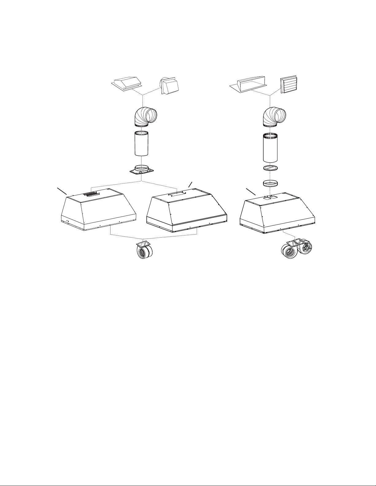
Plan where and how the ductwork will be installed. Access to the top of the hood is
Roof cap
preferred for connection of ductwork.
Install proper-sized ductwork, elbows and roof or wall cap for the type of blower you
are installing. If installing CP34 or CP35 power pack, use 8” round ductwork and if
installing CP37 power pack, use 10” round ductwork. Use 2” metal foil duct tape to
seal duct joints.
The minimum hood distance above cooktop must not be less than 24”. A
maximum of 30” above cooktop is recommended for best capture of cooking
impurities.
Distances over 30” are at the installer and users discretion.
Run 3-wire power supply cable to installation location. Its length should extend at least
4 feet below the bottom of the custom hood.
Wall
cap
HH0101A
ODELS CP34 & CP35 (SINGLE BLOWER)
M
OR CP37 (DUAL BLOWER) TYPICAL DUCTWORK
8” round duct for CP34 & CP35
or 10” round duct for CP37
8” round elbow for CP34 & CP35
or 10” round elbow for CP37
10” in line
vertical damper for CP37
8” round adapter & damper
for CP34 & CP35 or
10” round adapter for CP37
Power pack
24” to 30”
above
cooking surface
3. CUSTOM HOOD PREPARATION
WARNING
When building a custom hood, always follow all applicable construction codes and standards.
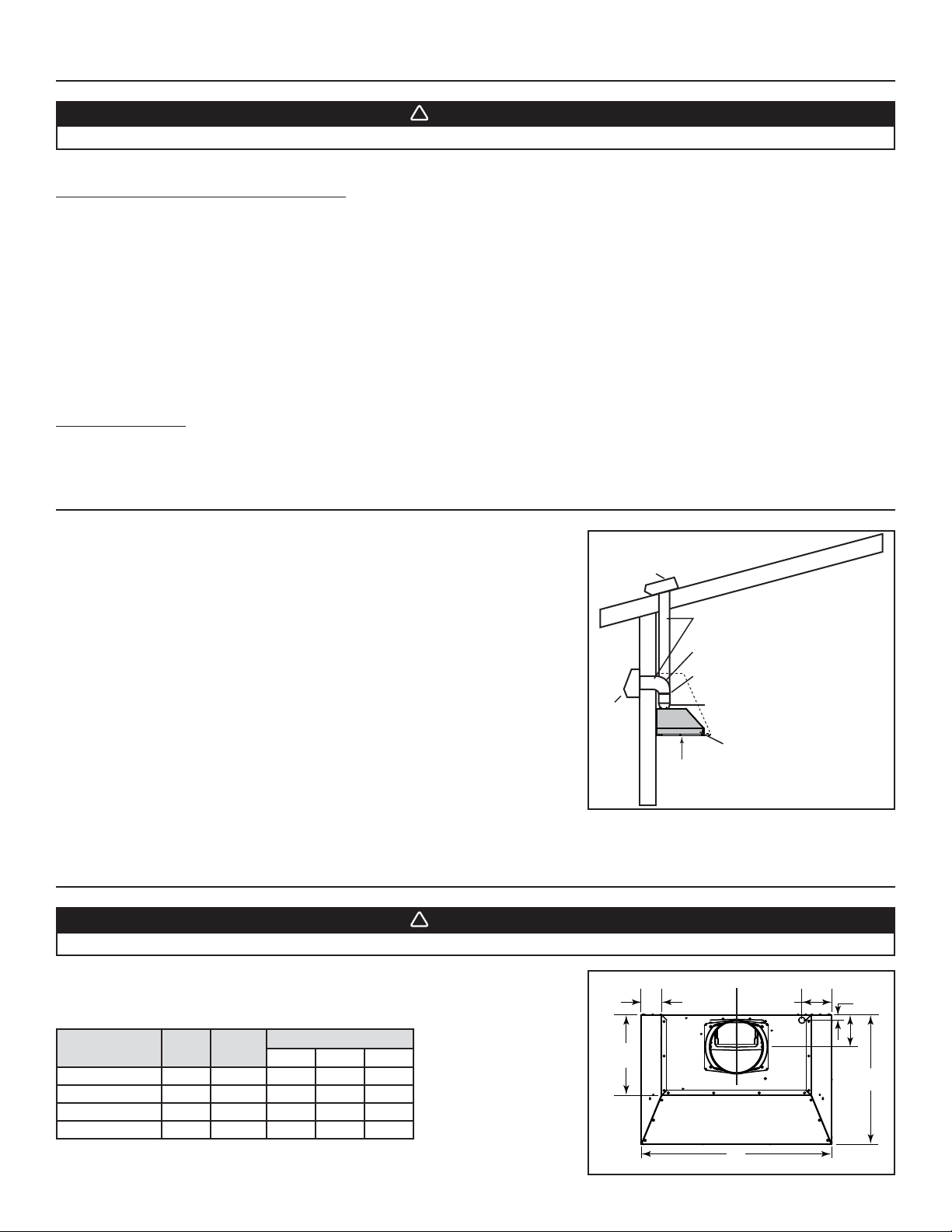
The custom hood must be constructed to fit the size and shape of the CP34, CP35 or
the CP37 power pack models.
See chart and illustration for details.
POWER PACK
MODEL
CP34 AND CP35 30” 33 LB.195⁄16”287⁄16”47⁄8”
CP37 48” 56.5 LB.229⁄16”467⁄16”57⁄8”
WIDTH
TOTAL
WEIGHT
36” 37.2
42” 41.6 LB.195⁄16”407⁄16”47⁄8”
RANGE HOOD DIMENSIONS
A* B* C
5
LB.19
⁄16”347⁄16”47⁄8”
* Dimensions A and B include rivets head.
4
3”
12”
HD0296A
REAR
B
FRONT
C
L
4½”
7/8
C
A
Page 5
3. CUSTOM HOOD PREPARATION (CONT’D)
!
To minimize the gap around the power pack, take actual width and depth measurements
of power pack and add 1/16” to get D and E measurements. Cut the hole in the bottom
of the cabinet according to dimensions. See chart and illustration for details.
POWER PACK
MODEL
CP34 AND CP35 30” 193⁄8” 28½”
CP37 48” 22
WIDTH
36” 193⁄8” 34½”
42” 193⁄8” 40½”
CUTOUT
DIMENSIONS
DE
5
⁄8” 46½”
D
E
HD0367
4. MOUNT CUSTOM HOOD INTERNAL FRAMEWORK
WARNING
The framework must be positively secured to wall studs or other wooden framework behind the drywall. Make sure
it is capable of supporting its own weight and the weight of the CP34, CP35 or CP37. Failure to do so may cause
personal injury or damage to countertop or cooktop.
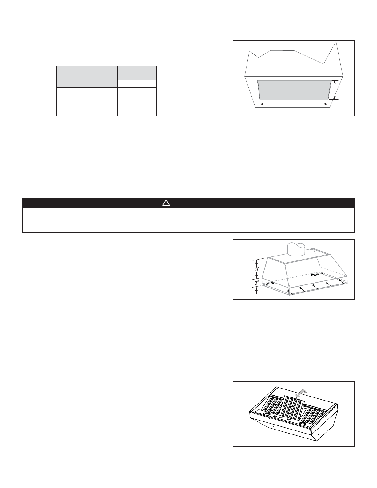
The CP34, CP35 and CP37 power pack models are supported by the custom hood
internal framework with screws provided in parts bag.
Since the CP34, CP35 and CP37 power pack models mounting holes are located in
front and rear sides (see illustration at right), plan to install wood frame at front and
sides for support.
5. REMOVE FILTERS
Remove tape on filters. Remove filters from power pack and set aside.
NOTE: It is recommended to start with the center one(s).
HH0102A
HD0295
5
Page 6
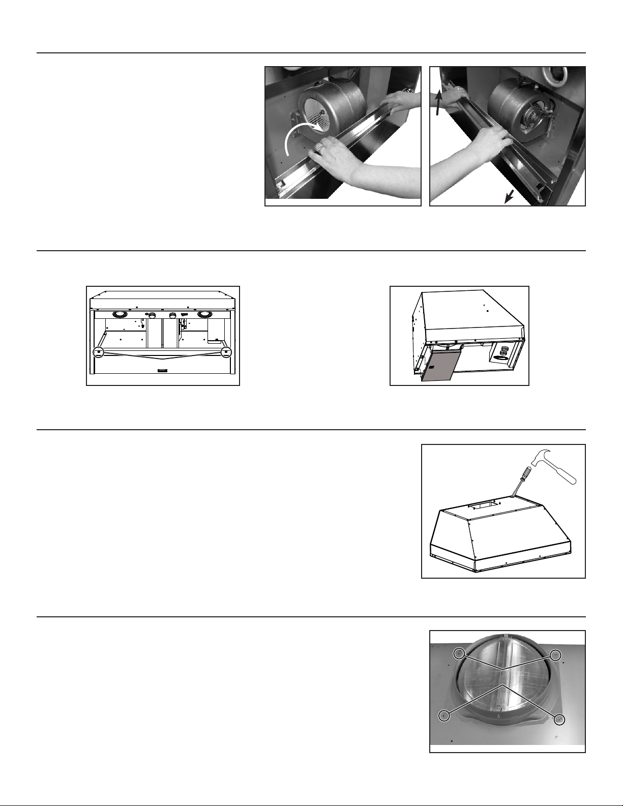
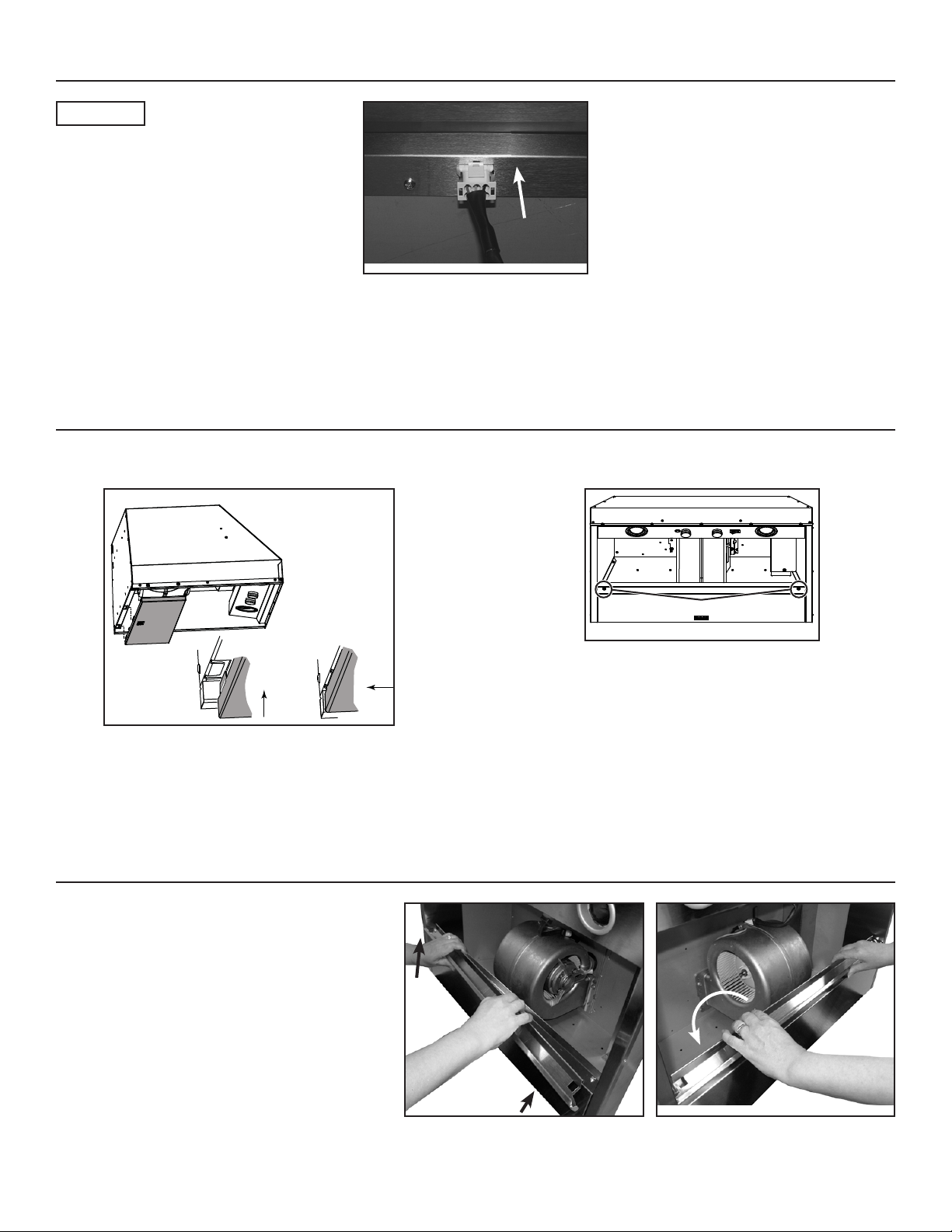
6. REMOVE GREASE DRIP RAIL
A. Lift grease drip rail to disengage it from the bottom
panel.
B. Slide grease rail all the way to the left or right () and
lift the opposite end to disengage the other end from
the bottom panel (). Remove it from the power pack
and set aside for later use.
HD0291
7. REMOVE BOTTOM PANEL
Using a Phillips screwdriver, remove both bottom panel retaining
screws and set aside.
RETAINING SCREW LOCATIONS
HO0110
A
B
HD0292
Disassemble bottom panel from power pack and set aside.
HO0111
SIDE VIEW
8. REMOVE KNOCK-OUT OPENING
From inside the power pack, remove the wiring cover by removing 2 retaining screws and set
aside. Punch out the electrical knockout hole on top of the power pack. Install the wire clamp
(included in parts bag).
9. INSTALL ADAPTER/DAMPER (CP34 AND CP35 MODELS)
Using 4 no. 8 x 3/8” screws from parts bag, assemble the adapter/damper on the top of the power
pack. To ensure proper opening of the dampers, remove shipping tape if present. Seal all joints
with metal foil duct tape to eliminate air leaks.
HR0027
MOUNTING SCREW LOCATIONS
HJ0016
6
Page 7
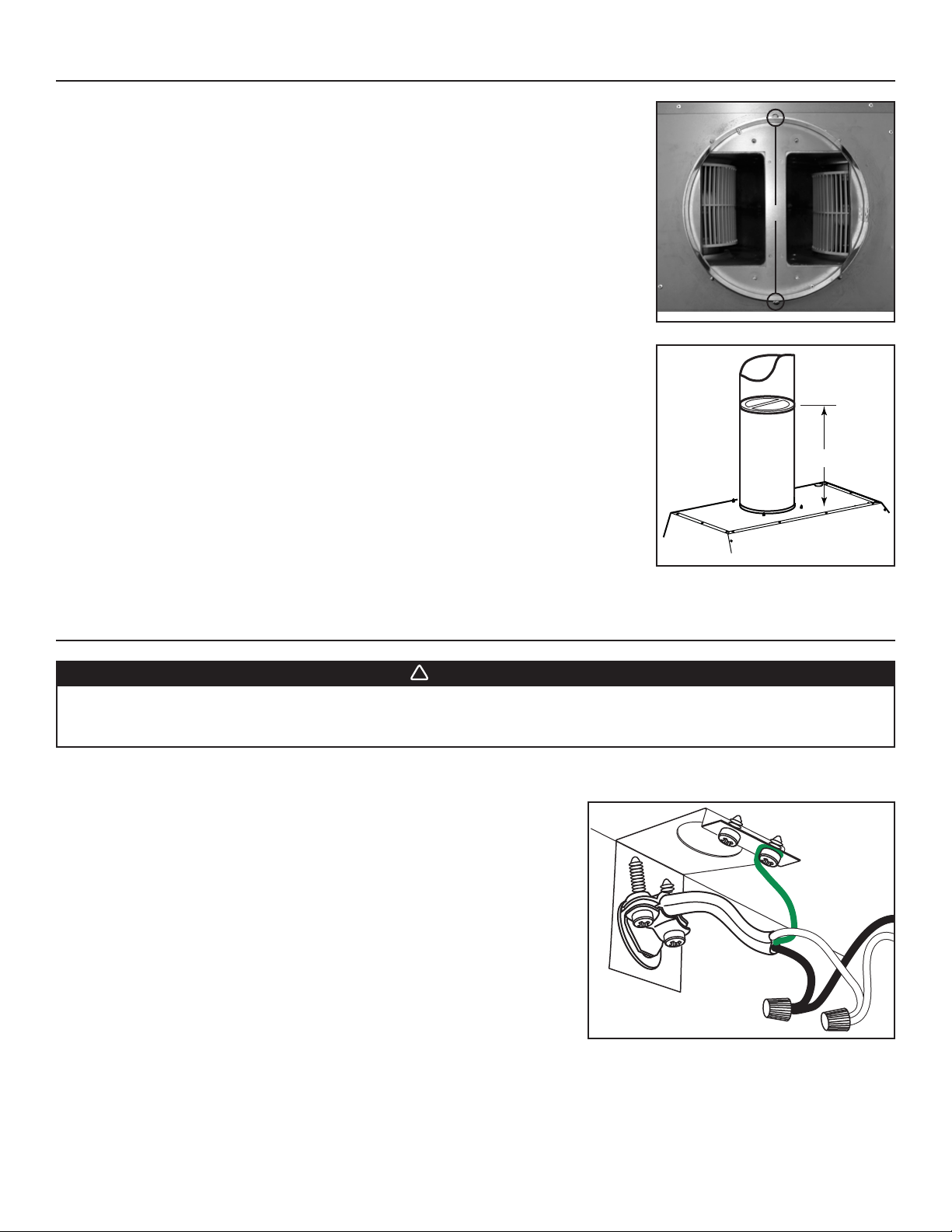
10. INSTALL ADAPTER AND DAMPER (CP37 MODEL ONLY)
!
Using 2 no. 8 x 3/8” screws from parts bag, assemble the adapter on the top of the power pack.
Seal all joints with metal foil duct tape to eliminate air leaks.
Install 10” damper inside the VERTICAL ductwork that will be attached to power pack. Do not
install in a horizontal ductwork or it will not open and close properly. Remove shipping tape if
present. To optimize airflow and quiet sound, position the damper at least 17” above the top of the
CP37 power pack; or as far as the duct run will allow (see figure at right). Secure the damper to
the duct with 3 no. 8 sheet metal screws (not provided). Ensure damper opens and closes freely.
Seal all joints with metal foil duct tape to eliminate air leaks.
11. CONNECT WIRING
MOUNTING SCREW LOCATIONS
HJ0026
17” min.
HJ0017A
WARNING
Risk of electric shock. Electrical wiring must be done by qualified personnel in accordance with all applicable
codes and standards. Before connecting wires, switch power off at service panel and lock service disconnecting
means to prevent power from being switched on accidentally.
Position the power pack below the installed custom hood. Insert the house wiring cable through the wire clamp previously installed in step 8.
Tighten the wire clamp to secure the cable.
Using the provided wire connectors, connect power pack wires to power cable into
wiring box.
Connect wires as follow: BLACK to BLACK, WHITE to WHITE and GREEN or bare
wire under ground screw. DO NOT FORGET TO CONNECT THE GROUND. Reinstall
wiring cover.
HE0059
7
Page 8
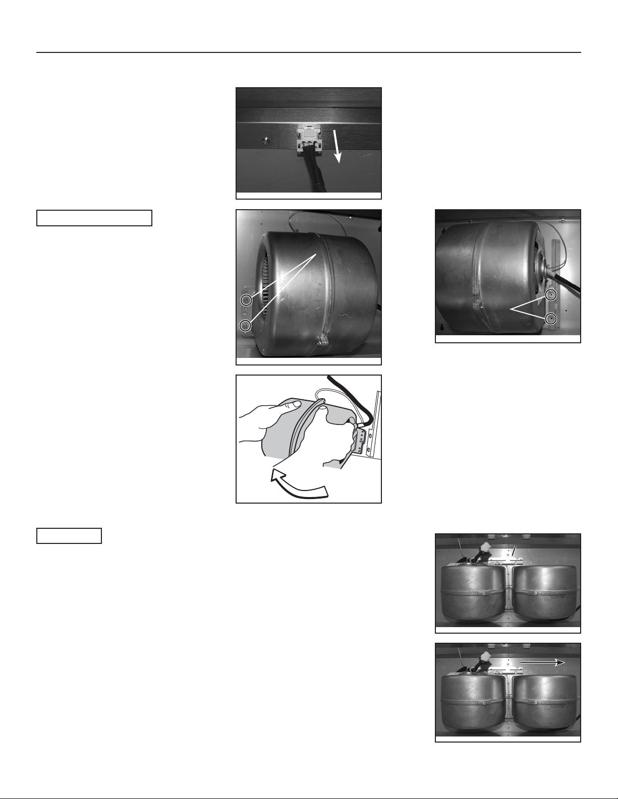
12. REMOVE BLOWER(S)
In order to ease the power pack alignment with existing ductwork, unplug and disassemble the blower(s) from the power pack before
installing the custom hood.
Unplug the blower(s)
HE0085
CP34 AND CP35 MODELS
LEFT SIDE MOUNTING
SCREWS LOCATION
Using a 5/16” socket, remove all blower mounting
screws from the inner top of the power pack. Set
the screws aside.
RIGHT SIDE
MOUNTING SCREWS
LOCATION
HD0269
Slide the blower to disengage its flange from the
retaining bracket. Set the blower aside.
HD0270
CP37 MODEL
For each blower, using a 5/16” socket, remove all blower mounting screws from the inner top of the
power pack front and rear brackets. Set the screws aside.
HD0282
BLOWERS FRONT BRACKET
BLOWERS REAR BRACKET
HD0297
For each blower, slide it to disengage its flanges from the retaining brackets. Set the blowers aside.
8
HD0298
Page 9
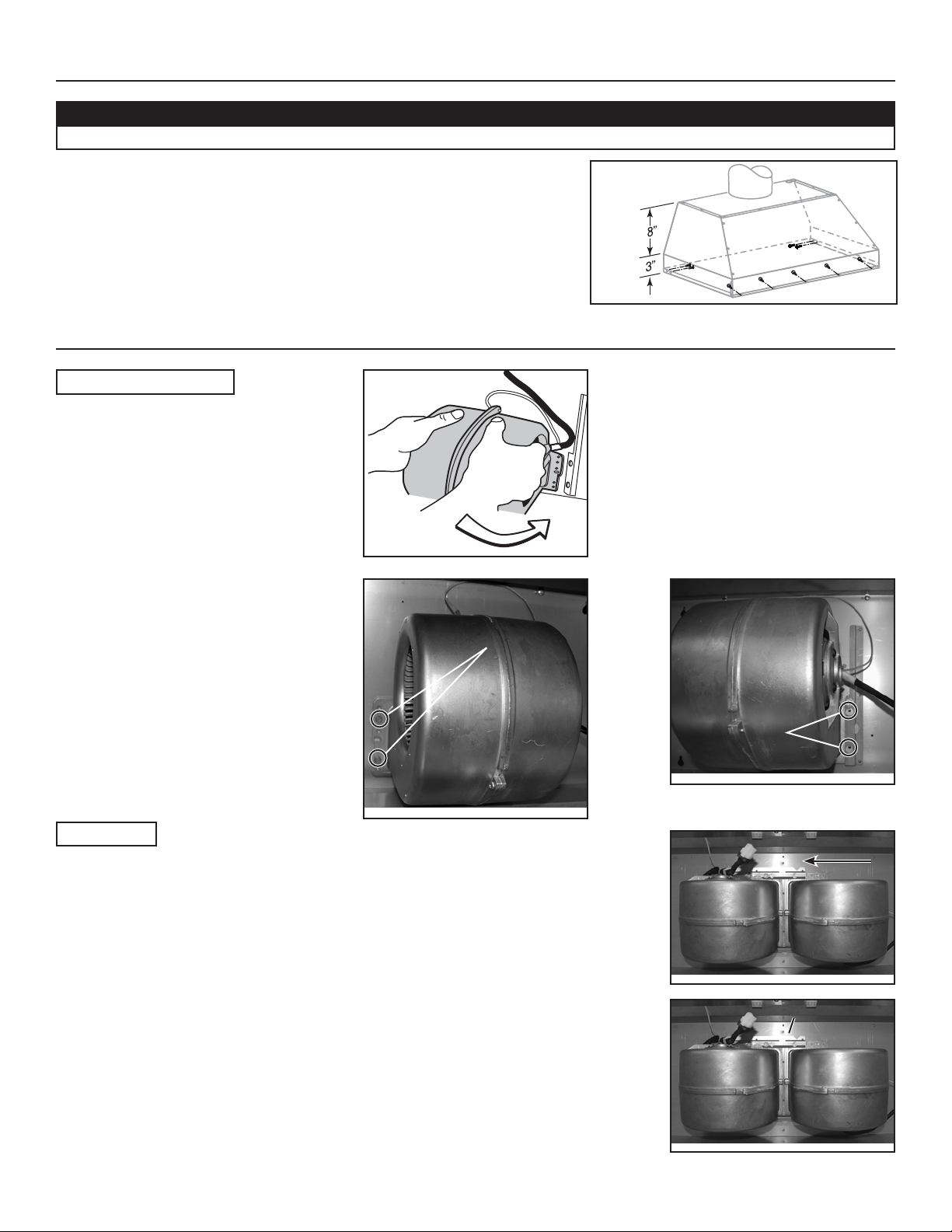
13. INSTALL POWER PACK
CAUTION
Take care not to kink ducting when installing the power pack.
Using provided no. 8 x 1/2” chrome plated screws, install the power pack inside the
custom hood. Start with 2 screws on front corners, then use 4 screws for sides and
use the remaining ones to finalize securing the front power pack. (See figure at right
for mounting screw specific locations.)
Make sure the adapter/damper (or the adapter) enters the ducting. When there is
access to the top of the power pack, seal connections with metal foil duct tape.
14. REINSTALL BLOWER(S)
CP34 AND CP35 MODELS
Slide the blower to engage its flange in the
retaining bracket.
HH0102A
HD0293
LEFT SIDE MOUNTING
SCREW LOCATIONS
Using a 5/16” socket, secure the blower to the
inner top of the power pack with all blower
mounting screws (previously removed in step 12).
HD0269
CP37 MODEL
For each blower, slide it to engage its flanges in both retaining brackets.
NOTE: Both blowers are identical and can be mounted on either side of the power pack.
RIGHT SIDE
MOUNTING SCREW
LOCATION
HD0282
HD0298
For each blower, using a 5/16” socket, secure the blower to the inner top of the power pack through
the front and rear brackets with all blower mounting screws (previously removed in step 12).
9
BLOWERS FRONT BRACKET
BLOWERS REAR BRACKET
HD0297
Page 10
14. REINSTALL BLOWER(S) (CONT’D)
ALL MODELS
Plug the blower(s) in.
HE0085
15. REINSTALL BOTTOM PANEL
Lift the bottom panel and engage the power pack metal tabs in
bottom panel slots, as shown in details A and B below.
SIDE VIEW
AB
HO0112
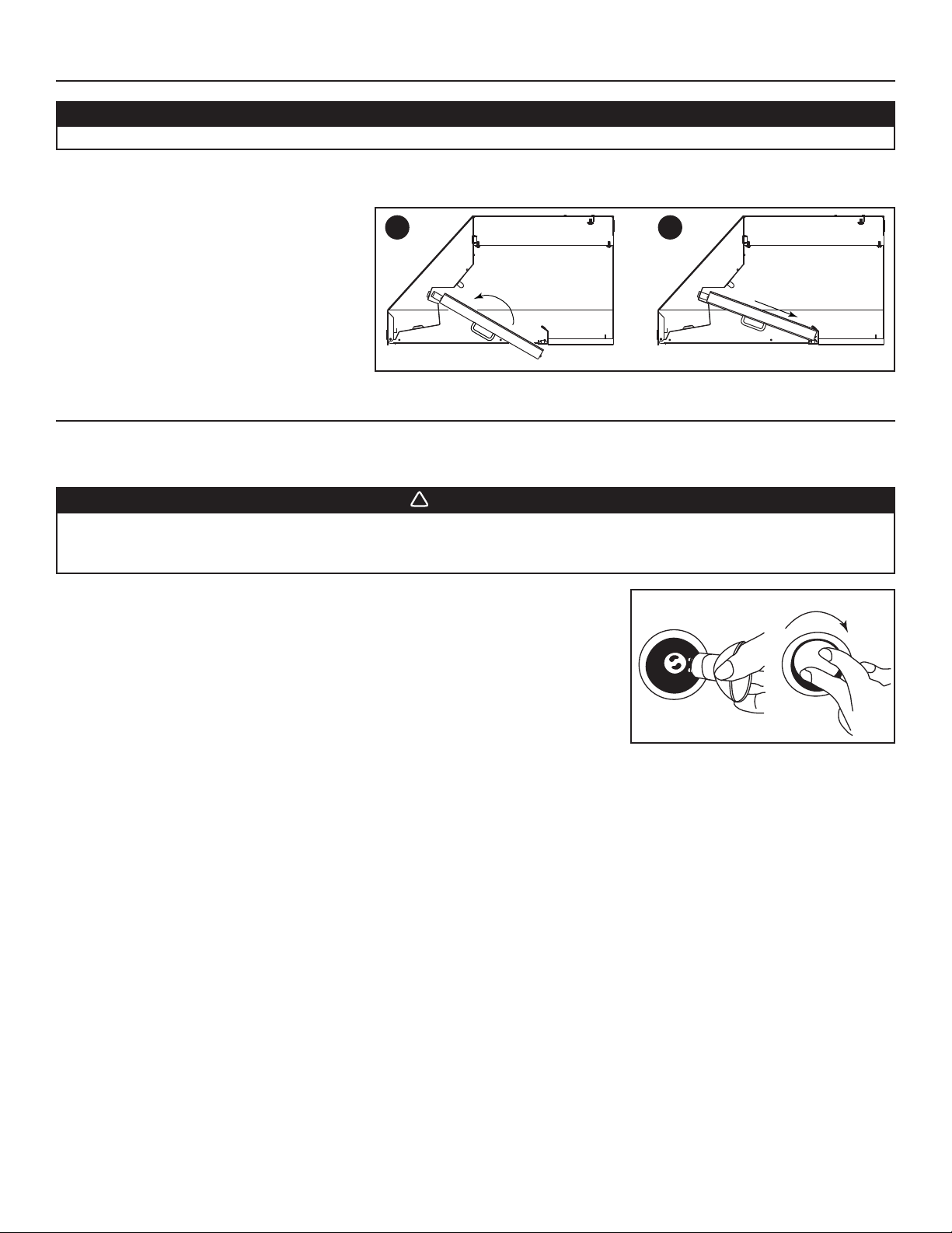
16. REINSTALL GREASE DRIP RAIL
Secure the bottom panel to the power pack using its screws
previously removed in step 7.
RETAINING SCREW LOCATIONS
HO0110
A. Insert one end of grease rail in power pack side ()
while lifting the other end over the bottom panel
edge ().
B. Center the grease drip rail over the bottom panel
edge and flip it to snap in place.
HD0292
10
A
B
HD0291
Page 11
17. REINSTALL BAFFLE FILTERS
!
CAUTION
Remove protective plastic film covering filters before installing them.
NOTE: Assemble the metal handles to the filters, using provided no. 8-32 x 1/4” screws, before installing them in the power pack.
It is recommended to install side filters first and finish with center one(s).
1
1. Insert one end of the filter into the upper channel
of the power pack.
2. Raise the other end toward the inside of power
pack and insert in the grease drip rail of the
power pack.
HD0299
2
18. LIGHT BULBS
This power pack requires shielded halogen lamps (120 V, 50 W, MR16 with GU10 base or PAR16 with GU10 base), included.
NOTE: Before using lamps, remove shipping tape on them (if present).
WARNING
Do not touch lamps during or soon after operation. Burns may occur. In order to prevent the risk of personal injury,
only install shielded halogen lamps. Also, never install a cool beam, a dichroic lamp, a lamp not suitable for use in
recessed luminaires or identified for use in enclosed fixtures.
1. Install the lamps by placing the bulb leads into their grooves in the socket.
2. Gently push upwards and turn clockwise until secure.
To remove lamps, gently push upwards and turn counterclockwise to disengage bulb leads
from their grooves.
NOTE: To ease removal of the bulbs, use a rubber dishwashing glove or use suction cup
tool available from Best. Contact Best Customer Service at 1-800-558-1711 to order
suction cup tool, part no. 99526707.
12
HO0090
11
Page 12
19. USE AND CARE
Baffle Filters
The baffle filters should be cleaned frequently. Use a warm detergent solution. Wash more often if your cooking style generates greater
grease — like frying foods or wok cooking.
Remove baffle filters by pushing them towards the back of hood and rotating filters downward. Baffle filters are dishwasher safe. Allow filters
to dry completely before reinstalling them in the power pack.
Clean all-metal filters in the dishwasher using a non-phosphate detergent. Discoloration of the filter may occur if using phosphate detergent
or as a result of local water conditions — but this will not affect filter performance. This discoloration is not covered by the warranty.
Rotary Control Knobs
Can be removed for cleaning but first, loosen the set screw using a 1/16” hexagonal key (available at your local hardware store).
Grease Drip Rail
The grease drip rail should be cleaned frequently. Remove it from the power pack (see step 6 on page 5) and use a warm detergent
solution. As with the baffle filters, wash more often if your cooking style generates greater grease — like frying foods or wok cooking. Allow
grease drip rail to dry completely before reinstalling it in the power pack.
Blower(s) Cleaning
Remove the filters in order to access the blower(s). Vacuum blower(s) to clean. Do not immerse in water.
Hood cleaning
Stainless steel cleaning:
Do:
• Regularly wash with clean cloth or rag soaked with warm water
and mild soap or liquid dish detergent.
• Always clean in the direction of original polish lines.
• Always rinse well with clear water (2 or 3 times) after cleaning.
Wipe dry completely.
• You may also use a specialized household stainless steel
cleaner.
Don’t:
• Use any steel or stainless steel wool or any other scrapers to
remove stubborn dirt.
• Use any harsh or abrasive cleansers.
• Allow dirt to accumulate.
• Let plaster dust or any other construction residues reach the
power pack. During construction/renovation, cover the power
pack to make sure no dust sticks to stainless steel surface.
Avoid when choosing a detergent:
- Any cleaners that contain bleach will attack stainless steel.
- Any products containing: chloride, fluoride, iodide, bromide will deteriorate surfaces rapidly.
- Any combustible products used for cleaning such as acetone, alcohol, ether, benzol, etc., are highly explosive and should never be
used close to a range.
12
Page 13
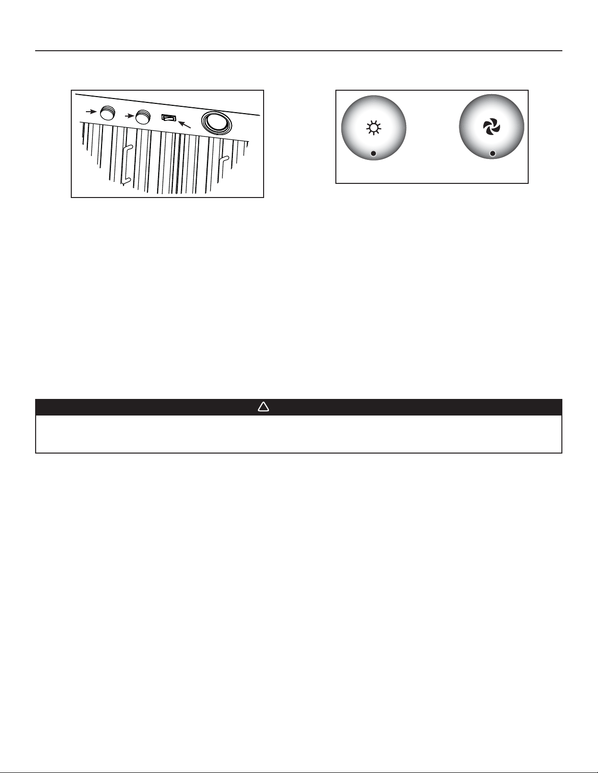
20. OPERATION
!
Always turn your hood on before you begin cooking to establish an air flow in the kitchen. Let the blower run for a few minutes to clear the
air after you turn off the range. This will help keep the whole kitchen cleaner and brighter.
1
2
3
HC0039
HC0038
1) HALOGEN LIGHT KNOB
2) BLOWER SPEED CONTROL KNOB
3) ON/OFF BLOWER SWITCH
COOKTOP LIGHTING (HALOGEN)
A rotary 3-position knob (1) controls the halogen lights (OFF - low intensity - high intensity).
BLOWER
The blower is operated using two controls.
Use the on/off rocker switch (3) to start and stop the blower. When turned on, the blower operates at the previous setting of the speed
control (2).
Turn the speed control knob counterclockwise to increase blower speed – clockwise to decrease speed.
HEAT SENTRY™
This hood is equipped with a Heat Sentry™ thermostat. This thermostat is a device that will turn on or speed up the blower if it senses
excessive heat above the cooking surface.
1) If blower is OFF - it turns blower ON to HIGH speed.
2) If blower is ON at a lower speed setting – it turns the blower up to HIGH speed.
1) HALOGEN LIGHT KNOB
2) BLOWER SPEED CONTROL KNOB
AB
WARNING
The HEAT SENTRY can start the blower during a range top fire or other excessive heat situations even if the hood
is turned off. In this case, it is impossible to turn the blower OFF with blower switch. If you must stop the blower,
do it from the main electrical panel.
When the temperature level drops to normal, the blower will return to its original setting.
13
Page 14

21. WARRANTY
ONE-YEAR LIMITED WARRANTY
Broan-NuTone LLC (“Broan-NuTone”) warrants to the original consumer purchaser of its products that such products will be free
from defects in materials or workmanship for a period of one year from the date of original purchase. THERE ARE NO OTHER
WARRANTIES, EXPRESS OR IMPLIED, INCLUDING, BUT NOT LIMITED TO, IMPLIED WARRANTIES OF MERCHANTABILITY OR
FITNESS FOR A PARTICULAR PURPOSE.
During this one-year period, Broan-NuTone will, at its option, repair or replace, without charge, any product or part which is found to be
defective under normal use and service.
THIS WARRANTY DOES NOT EXTEND TO FLUORESCENT LAMP STARTERS, TUBES AND BULBS, FUSES, FILTERS, DUCTS,
ROOF CAPS, WALL CAPS AND OTHER ACCESSORIES FOR DUCTING. This warranty does not cover (a) normal maintenance and
service or (b) any products or parts which have been subject to misuse, negligence, accident, improper maintenance or repair (other
than by Broan-NuTone), faulty installation or installation contrary to recommended installation instructions.
The duration of any implied warranty is limited to the one-year period as specified for the express warranty. Some states or provinces
do not allow limitation on how long an implied warranty lasts, so the above limitation may not apply to you.
BROAN-NUTONE’S OBLIGATION TO REPAIR OR REPLACE, AT BROAN-NUTONE’S OPTION, SHALL BE THE PURCHASER’S
SOLE AND EXCLUSIVE REMEDY UNDER THIS WARRANTY. BROAN-NUTONE SHALL NOT BE LIABLE FOR INCIDENTAL,
CONSEQUENTIAL OR SPECIAL DAMAGES ARISING OUT OF OR IN CONNECTION WITH PRODUCT USE OR PERFORMANCE.
Some states or provinces do not allow the exclusion or limitation of incidental or consequential damages, so the above
limitation or exclusion may not apply to you.
This warranty gives you specific legal rights, and you may also have other rights, which vary from state to state or province to another.
Any modification performed on this product without the authorization of Broan-NuTone will void this warranty. This warranty supersedes
all prior warranties.
To qualify for warranty service, you must (a) notify Broan-NuTone at the address or telephone number stated below, (b) give the model
number and part identification and (c) describe the nature of any defect in the product or part. At the time of requesting warranty service,
you must present evidence of the original purchase date.
®
Best
, 926 W. State Street, Hartford, WI 53027 (1-800-558-1711)
www.bestrangehoods.com
14
Page 15
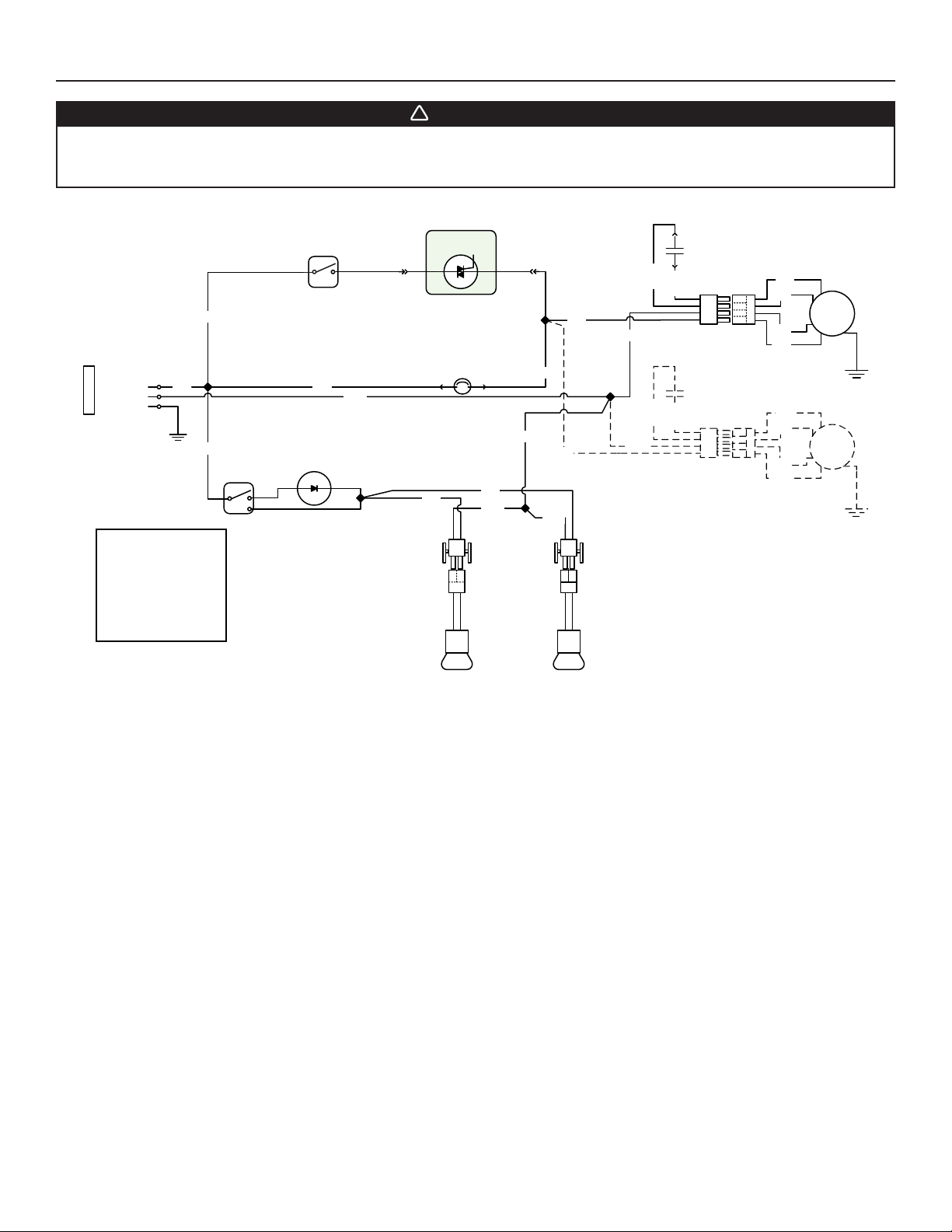
22. WIRING DIAGRAM
!
WARNING
Risk of electrical shock. Electrical wiring must be done by qualified personnel in accordance with all applicable
codes and standards. Before connecting wires, switch power off at service panel and lock service disconnecting
means to prevent power from being switched on accidentally.
NEUTRAL
GROUND
120 V AC
LINE
BLK
COLOR CODE
BLK BLACK
BLU BLUE
BRN BROWN
RED RED
WHT WHITE
YEL YELLOW
HE0092A
BLK
BLK
LAMP
SWITCH
L 1
FAN
SWITCH
BLU
WHT
2
SPEED
CONTROL
THERMOSTAT
YEL
LAMP
HS
YEL
WHT
WHT
BLU
LAMP
WHT
BLK
BLK
WHT
WHT
BLU
BLU
BLU
BLU
BRN
BLU
RED
BLK
BRN
BLU
RED
BLK
M
M
15
Page 16

23. SERVICE PARTS
Best CP34, CP35
& CP37 Series
2
1
4
3
5
7
6
16
10
13
8
9
14
11
HL0110
KEY
PART NO.DESCRIPTION
NO.
1 SV08543 A
2 SV08541 ADAPTER 10” ROUND ---1
3 SV08097 INTERNAL BLOWER 1112
4 SV16569 LAMP SHELL, SOCKET & TRIM ASS ‘Y 2222
5 SV03435 HEAT SENTRY™ THERMOSTAT 1111
6 SV08338 LIGHT SWITCH 1111
7 SV03501 SPEED CONTROL 1111
8 SV08578 BLOWER AND LIGHT KNOBS (2 KNOBS) 1111
9 SV08548 BLOWER ROCKER SWITCH 1111
10 SV17852 FILTER FILLER (PAIR) --1-
SV17870 G
SV17871 GREASE RAIL 36” - 1 - -
11
SV17872 GREASE RAIL 42” - - 1 SV17873 GREASE RAIL 48” - - - 1
12 SV05869 BEST LOGO 1111
SV17600 BAFFLE FILTER 8.84” X 9.80” 3145
13
SV17603 B
14 SV08337 F
15 SV07680 B
16 SV05921 S
* SV08542 10” R
* SV08342 CAPACITOR 25 μF 1111
* SV08544 INSTALLATION GUIDE 1111
* SV08545
* NOT SHOWN.
DAPTER/DAMPER 8” ROUND 111-
REASE RAIL 30” 1 - - -
AFFLE FILTER 11.84” X 9.80” 0200
ILTER SPRING (SET OF 6) 1111
AFFLE FILTER HANDLE WITH SCREWS 3345
HIELDED HALOGEN LAMPS (120 V, 50 W, GU-10) 2222
OUND VERTICAL IN-LINE DAMPER ---1
PARTS BAG: 2 WIRE CONNECTORS, 1 WIRE CLAMP, 4 SCREWS NO. 8 X 3/8”,
9 CHROME PLATED SCREWS NO. 8 X 1/2”, 10 MECHANICAL SCREWS NO. 8-32 X 1/4”
12
15
16
REPLACEMENT PARTS AND REPAIRS
In order to ensure your unit remains in
good working condition, you must use
Broan-NuTone genuine replacement
parts only. Broan-NuTone genuine
replacement parts are specially
designed for each unit and are
manufactured to comply with all the
applicable certification standards and
maintain a high standard of safety.
Any third party replacement part
used may cause serious damage and
drastically reduce the performance
level of your unit, which will result
in premature failing. Broan-NuTone
recommends to contact a certified
service depot for all replacement
parts and repairs.
QTY. (POWER PAC K WIDTH)
30" 39" 45" 48"
1111
Page 17

GUIDE D’INSTALLATION
HB0078
SÉRIES CP34, CP35 ET CP37
! !
CONÇUES POUR USAGE DOMESTIQUE SEULEMENT
LIRE ET CONSERVER CES DIRECTIVES
INSTALLATEUR : LAISSER CE GUIDE AU PROPRIÉTAIRE.
PROPRIÉTAIRE : DIRECTIVES D’UTILISATION ET D’ENTRETIEN
EN PAGES 28 ET 29.
BEST; Hartford, Wisconsin www.BestRangeHoods.com 800 558-1711
Pour enregistrer votre produit en ligne ou pour obtenir plus d’information, consultez notre site www.BestRangeHoods.com
SV08544 rév. 10
Page 18

!
AVERTISSEMENT
!
AVERTISSEMENT
AFIN DE RÉDUIRE LES RISQUES D’INCENDIE,
D’ÉLECTROCUTION OU DE BLESSURES CORPORELLES,
SUIVEZ LES DIRECTIVES SUIVANTES :
1. N’utilisez cet appareil que de la façon prévue par le
manufacturier. Si vous avez des questions, contactez le
manufacturier à l’adresse ou au numéro de téléphone indiqués
dans la garantie.
2. Avant de réparer ou de nettoyer l’appareil, couper l’alimentation
électrique en verrouillant le panneau de distribution afin
d’éviter sa remise en marche accidentelle. Si le panneau de
distribution ne peut être verrouillé, y fixer un avertissement en
évidence, telle qu’une étiquette de couleur vive.
3. Les travaux d’installation et de raccordement électrique doivent
être effectués par une personne qualifiée, conformément
aux codes et aux standards de construction, incluant ceux
concernant la protection contre les incendies.
4. Une quantité d’air adéquate est requise afin d’assurer une
bonne combustion et l’évacuation des gaz par la cheminée
dans le cas des équipements alimentés au gaz afin de prévenir
les retours de cheminée. Conformez-vous aux instructions et
aux standards de sécurité des manufacturiers d’équipement de
chauffage, tel qu’ils sont publiés par la National Fire Protection
Association (NFPA) et l’American Society for Heating,
Refrigeration and Air Conditioning Engineers (ASHRAE) ainsi
que les responsables des codes locaux.
5. Veillez à ne pas endommager le câblage électrique ou d’autres
équipements non apparents lors de la découpe ou du perçage
du mur ou du plafond.
6. Les ventilateurs avec conduits doivent toujours évacuer l’air
à l’extérieur.
7. Ne pas utiliser cet appareil avec une commande de vitesse à
semi-conducteur.
8. Afin de réduire les risques d’incendie, n’utilisez que des conduits
de métal.
9. Cet appareil doit être mis à la terre.
10. Lorsqu’une réglementation est en vigueur et qu’elle comporte
des exigences d’installation et/ou de certification plus
restrictives, lesdites exigences prévalent sur celles de ce
document et l’installateur entend s’y conformer à ses frais.
AFIN DE RÉDUIRE LES RISQUES DE FEU
DE CUISINIÈRE :
a) Ne jamais laisser les appareils de cuisson sans surveillance
lorsqu’ils sont réglés à feu vif. Les débordements engendrent
de la fumée et des déversements graisseux pouvant
s’enflammer. Chauffez l’huile lentement, à feu doux ou moyen.
b) Mettez toujours la hotte en marche lorsque vous cuisinez à feu
vif ou que vous cuisinez des mets flambés (par ex. : crêpes
Suzette, cerises jubilé, steaks au poivre flambés).
c) Nettoyez régulièrement la (les) roue(s) du ventilateur. Ne
laissez pas la graisse s’accumuler sur le ventilateur, les filtres
ou les conduits d’évacuation.
d) Utilisez le bon format de casserole. Servez-vous toujours de
casseroles et d’ustensiles appropriés à la dimension de la
surface chauffante.
AFIN D’ÉVITER TOUT RISQUE DE BLESSURES LORS D’UN
FEU DE CUISINIÈRE, SUIVEZ CES DIRECTIVES* :
1. Étouffez les flammes avec un couvercle hermétique, une tôle à
biscuits ou un plateau métallique et ensuite, éteindre le brûleur.
PRENEZ SOIN D’ÉVITER les brûlures. SI LES FLAMMES
NE S’ÉTEIGNENT PAS IMMÉDIATEMENT, ÉVACUEZ LES
LIEUX ET APPELEZ LES POMPIERS.
2. NE PRENEZ JAMAIS UNE CASSEROLE EN FLAMMES
DANS VOS MAINS. Vous pourriez vous brûler.
3. N’UTILISEZ PAS D’EAU, incluant un linge à vaisselle ou une
serviette mouillée, cela pourrait occasionner une violente
explosion de vapeur.
4. N’utilisez un extincteur QUE DANS LE CAS OÙ :
A. Vous savez qu’il s’agit d’un extincteur de classe ABC et
que vous en connaissez le fonctionnement.
B. L’incendie est petit et limité à l’endroit où il a débuté.
C. Les pompiers ont été avisés.
D. Vous pouvez combattre l’incendie en ayant accès à une sortie
de secours.
*Tirées du Kitchen Fire Safety Tips publié par la NFPA.
ATTENTION
1. Pour une utilisation à l’intérieur seulement.
2. Pour usage domestique seulement. Ne pas utiliser pour
évacuer des vapeurs ou des matières dangereuses
ou explosives.
3. Afin d’éviter tout dommage au moteur et de débalancer ou de
rendre bruyante la roue du moteur, garder votre appareil à l’abri
des poussières de gypse et de construction/rénovation, etc.
4. Le moteur de votre hotte encastrable possède une protection
thermique qui éteindra automatiquement le moteur s’il devient
surchauffé. Le moteur redémarrera automatiquement une
fois refroidi. Si le moteur continue à arrêter et à redémarrer,
faites-le vérifier.
5. La distance minimale entre le bas de votre hotte et la surface
de cuisson ne doit pas être inférieure à 24 po. Un maximum
de 30 po au-dessus de la surface de cuisson est recommandé
pour une meilleure évacuation des odeurs de cuisson.
6. Deux installateurs sont recommandés lors de l’installation vu
la grande dimension et le poids de cet appareil.
7. Afin de réduire les risques d’incendie, assurez-vous d’évacuer
l’air à l’extérieur. Ne pas évacuer l’air dans des espaces
restreints comme l’intérieur des murs ou plafond ou dans le
grenier, faux plafond ou garage.
8. Cet appareil est équipé d’un thermostat pouvant faire
démarrer le ventilateur automatiquement. Afin de réduire le
risque de blessure, couper le courant à partir du panneau
électrique et le verrouiller ou apposer un avertissement sur le
panneau afin de prévenir que la hotte ne soit mise en marche
accidentellement.
9. À cause de la grande capacité d’évacuation de cet appareil,
il est recommandé d’ouvrir une fenêtre dans ou près de la
cuisine afin de remplacer l’air évacué.
10. Afin de réduire les risques d’incendie et d’électrocution, les
modèles Best de la série CP34, CP35 et CP37 doivent être
installés uniquement avec leurs ventilateurs intérieurs intégrés.
Aucun autre ventilateur ne doit être utilisé.
11. Veuillez consulter l’autocollant apposé à l’intérieur du produit
pour plus d’information ou autres exigences.
18
Page 19

- SYSTÈMES DE HOTTES ENCASTRABLES CP34, CP35 ET CP37
ADAPTATEUR/VOLET 8 PO ROND
(FOURNI AVEC LES HOTTES
ENCASTRABLES À VENTILATEUR SIMPLE)
HOTTE ENCASTRABLE
CP34*
MODÈLE 634 OU 644
(CAPUCHON DE TOIT)
COUDE AJUSTABLE
DE 8 PO ROND
C
ONDUIT STANDARD
DE
8 PO ROND)
ODÈLE 643
M
(C
APUCHON MURAL
8 PO ROND)
HOTTE
ENCASTRABLE
CP35
M
ODÈLE 437
(C
APUCHON DE TOIT
À HAUT RENDEMENT)
MODÈLE 418
(COUDE AJUSTABLE
DE 10 PO ROND)
MODÈLE 410
(CONDUIT DE 10 PO ROND
SECTIONS DE 2 PI)
—
HOTTE
ENCASTRABLE
CP37
ODÈLE 441
M
(C
APUCHON MURAL
10 PO ROND)
OLET VERTICAL EN LIGNE DE
V
10 PO ROND (FOURNI AVEC LA HOTTE
ENCASTRABLE À VENTILATEUR DOUBLE)
ADAPTATEUR DE 10 PO ROND
(FOURNI AVEC LA HOTTE
ENCASTRABLE À VENTILATEUR DOUBLE)
HL0122
ENTILATEUR SIMPLE (600 PCM)
V
(FOURNI AVEC LES HOTTES
ENCASTRABLES DE 30 PO, 36 PO
ET 42 PO SEULEMENT)
E RÉDUCTEUR DE DÉBIT 300 PCM
*L
EST
INTÉGRÉ AU MODÈLE CP34
V
ENTILATEUR DOUBLE (1200 PCM)
(FOURNI AVEC LA HOTTE ENCASTRABLE
DE 48 PO SEULEMENT)
19
Page 20

1. PRÉPARER L’INSTALLATION
!
!
AVERTISSEMENT
Il est recommandé de porter des lunettes et des gants de sécurité lors de l’installation, de l’entretien et de la
réparation de cet appareil.
NOTE : Avant de commencer l’installation, vérifier le contenu de la boîte. Si des pièces sont manquantes ou endommagées, contacter
le manufacturier.
S’assurer que les articles suivants soient inclus :
- Hotte encastrable
- Accessoires : • Filtres à chicane :
CP34 et CP35 : 3 pour les modèles de 30 po et 36 po de largeur, 4 pour le modèle de 42 po de largeur
CP37 : 5 pour ce modèle de 48 po de largeur
• Poignées des filtres à chicane (fixées avec du ruban adhésif à l’intérieur de la hotte encastrable) :
CP34 et CP35 : 3 pour les modèles de 30 po et 36 po de largeur et 4 pour le modèle de 42 po de largeur
CP37 : 5 pour ce modèle de 48 po de largeur
• 2 ampoules halogènes avec écran (120 V, 50 W, MR16 avec culot GU10 ou PAR16 à culot GU10)
• Adaptateur/volet de 8 po rond (fourni avec les hottes encastrables à ventilateur simple)
• Volet vertical en ligne de 10 po rond (fourni avec la hotte encastrable à ventilateur double)
• Adaptateur de 10 po rond (fourni avec la hotte encastrable à ventilateur double)
• Sac de pièces incluant : 1 serre-fils, 2 capuchons de connexion, 4 vis n° 8 x 3/8 po, 9 vis plaquées chrome n° 8 x 1/2 po,
10 vis n° 8-32 x 1/4 po. Jeter les vis excédentaires s’il y a lieu.
Pièces vendues séparément :
Conduits, coudes, capuchons de mur ou de toit. Consulter la page 19 pour la liste complète des accessoires de ventilation et les numéros
de modèle.
NOTE : Lors de l’installation, protéger la surface de cuisson et le comptoir de cuisine.
2. INSTALLER LES CONDUITS ET LE CÂBLAGE ÉLECTRIQUE
Déterminer à quel endroit et comment les conduits seront installés. Un accès au
dessus de la hotte est préférable pour le raccordement des conduits.
Installer des conduits de dimensions appropriées, coude(s) et capuchon de mur ou
de toit selon le type de ventilateur. Pour l’installation de la hotte encastrable CP34 ou
CP35, utiliser des conduits ronds de 8 po et pour l’installation de la hotte encastrable
CP37, utiliser des conduits ronds de 10 po. Utiliser du ruban adhésif de métal de 2 po
pour assurer l’étanchéité des joints.
La distance minimale entre le bas de votre hotte et la surface de cuisson ne doit
pas être inférieure à 24 po. Un maximum de 30 po au-dessus de la surface de
cuisson est recommandé pour une meilleure évacuation des odeurs de cuisson.
Une distance de plus de 30 po demeure à la discrétion de l’installateur et de l’utilisateur.
Acheminer le câble d’alimentation électrique à 3 conducteurs jusqu’à l’emplacement
de la hotte. Le câble devrait excéder de 4 pi le dessous de la hotte.
(
Capuchon de toit
Conduits ronds de
8 po pour CP34 & CP35
ou de 10 po pour CP37
Coude rond de 8 po pour CP34 &
CP35 ou de 10 po pour CP37
Volet vertical
10 po rond pour CP37
Capuchon
de mur
De 24 po à 30 po
au-dessus de la
HH0101F
NSTALLATION TYPE MODÈLES CP34 ET CP35
I
VENTILATEUR SIMPLE) OU CP37 (VENTILATEUR DOUBLE)
surface de cuisson
Adaptateur et volet
8 po rond pour CP34 & CP35
ou adaptateur 10 po rond
pour CP37
Hotte encastrable
3. PRÉPARER L’ARMOIRE POUR HOTTE
AVERTISSEMENT
Toujours suivre les codes et standards en vigueur lors de la contruction de l’armoire pour hotte.
Construire l’armoire en fonction du format et du poids total des hottes encastrables
CP34, CP35 ou CP37.
Consulter le tableau et l’illustration pour plus de détails.
MODÈLE DE HOTTE
ENCASTRABLE
CP34 ET CP35 30 PO 33 LB 195⁄16 PO 287⁄16 PO 47⁄8 PO
CP37 48 PO 56,5 LB 229⁄16 PO 467⁄16 PO 57⁄8 PO
LARGEUR
36 PO 37,2 LB 195⁄16 PO 347⁄16 PO 47⁄8 PO
42 PO 41,6 LB 195⁄16 PO 407⁄16 PO 47⁄8 PO
POIDS
TOTAL
* Les têtes de rivets sont incluses dans les dimensions A et B.
DIMENSIONS DE LA HOTTE
A* B* C
12 po
HD0296F
20
3 po
ARRIÈRE
C
L
B
AVANT
4½ po
7/8 po
C
A
Page 21

3. PRÉPARER L’ARMOIRE POUR HOTTE (SUITE)
!
Afin de minimiser l’espace autour de la hotte encastrable, mesurer la longueur et
profondeur de celle-ci et ajouter 1/16 po pour obtenir les mesures de D et E. Découper
le trou dans la base de l’armoire selon les dimensions obtenues. Consulter le tableau
et l’illustration pour plus de détails.
MODÈLE DE HOTTE
ENCASTRABLE
CP34 ET CP35 30 PO 193⁄8 PO 28½ PO
CP37 48 PO 225⁄8 PO 46½ PO
LARGEUR
36 PO 193⁄8 PO 34½ PO
42 PO 193⁄8 PO 40½ PO
DIMENSIONS
DE LA DÉCOUPE
DE
D
E
HD0367
4. ASSEMBLER LA CHARPENTE DE L’ARMOIRE
AVERTISSEMENT
La charpente doit être fixée solidement aux montants ou autre structure derrière la cloison. S’assurer qu’elle
puisse supporter son propre poids en plus de celui de la CP34, CP35 ou de la CP37. Ne pas suivre cette directive
peut entraîner des blessures corporelles ou des dommages à la surface de cuisson ou au comptoir de cuisine.
Les hottes encastrables CP34, CP35 et CP37 sont fixées à la charpente de l’armoire
à l’aide des vis fournies dans le sac de pièces.
Puisque les trous d’assemblage des hottes encastrables CP34, CP35 et CP37 sont
situés à l’avant et sur les côtés arrière (voir l’illustration ci-contre), prévoir d’installer un
cadrage de bois à l’avant et de chaque côté pour supporter la hotte.
5. RETIRER LES FILTRES
Enlever le ruban adhésif des filtres. Retirer les filtres de la hotte encastrable et les
mettre de côté.
NOTE : Il est recommandé de commencer par le(s) filtre(s) du centre.
HH0102F
HD0295
21
Page 22

6. RETIRER LA GOUTTIÈRE
A. Soulever la goutière pour la dégager du
panneau inférieur.
B. Glisser la gouttière complètement vers la gauche ou
la droite () et soulever l’extrémité opposée pour la
dégager du panneau inférieur (). La retirer de la
hotte encastrable et la mettre de côté.
HD0291
7. RETIRER LE PANNEAU INFÉRIEUR
À l’aide d’un tournevis Phillips, retirer les deux vis de retenue
du panneau inférieur et les mettre de côté.
EMPLACEMENT DES VIS DE RETENUE
HO0110
A
B
HD0292
Retirer le panneau inférieur de la hotte encastrable et le mettre
de côté.
HO0111
VUE LATÉRALE
8. DÉFONCER L’OUVERTURE PRÉAMORCÉE
Par l’intérieur de la hotte encastrable, retirer le couvercle de la boîte de jonction en dévissant les
2 vis de fixation et les mettre de côté. Défoncer l’ouverture préamorcée pour le fil d’alimentation
électrique située sur le dessus de la hotte encastrable. Installer le serre-fil (fourni dans le sac
de pièces).
HR0027
9. INSTALLER L’ADAPTATEUR/VOLET (MODÈLES CP34 ET CP35)
À l’aide de 4 vis n° 8 x 3/8 po fournies dans le sac de pièces, assembler l’adaptateur/volet sur le
dessus de la hotte encastrable. Le cas échéant, retirer le ruban adhésif des volets pour assurer
leur bon fonctionnement. Sceller les joints avec du ruban adhésif de métal pour pour éliminer les
fuites d’air.
EMPLACEMENT DES VIS D’ASSEMBLAGE
22
HJ0016
Page 23

10. INSTALLER L’ADAPTATEUR ET LE VOLET (MODÈLE CP37 SEULEMENT)
!
À l’aide de 2 vis n° 8 x 3/8 po fournies dans le sac de pièces, assembler l’adaptateur sur le
dessus de la hotte encastrable. Sceller les joints avec du ruban adhésif de métal pour éliminer les
fuites d’air.
Installer le volet de 10 po à l’intérieur du conduit VERTICAL lequel sera rattaché à la hotte
encastrable. Ne pas l’installer dans un conduit horizontal car l’ouverture et la fermeture ne
pourraient se faire adéquatement. Retirer le ruban adhésif s’il y a lieu. Pour optimiser le débit d’air
et minimiser le bruit, placer le volet à au moins 17 po du dessus de la hotte encastrable CP37, ou
le plus éloigné possible selon la longueur du conduit (voir l’illustration ci-contre). Fixer le volet au
conduit à l’aide de 3 vis à métaux n° 8 (non fournies). S’assurer que le volet s’ouvre et se ferme
librement. Sceller les joints avec du ruban adhésif de métal pour éliminer les fuites d’air.
EMPLACEMENT DES VIS D’ASSEMBLAGE
HJ0026
17 po min.
HJ0017F
11. BRANCHEMENT ÉLECTRIQUE
AVERTISSEMENT
Risque d’électrocution. Le raccordement électrique doit être effectué par du personnel qualifié conformément
aux codes et aux standards. Avant d’effectuer le branchement, coupez l’alimentation électrique au panneau de
distribution et verrouillez-le pour éviter une mise en marche accidentelle.
Placer la hotte encastrable sous son armoire. Passer le cable d’alimentation électrique à travers le serre-fils précédemment installé à l’étape 8.
Serrer le serre-fils pour retenir le fil d’alimentation en place.
À l’aide des capuchons de connexion fournis, connecter les fils de la hotte aux fils
du câble d’alimentation dans la boîte de jonction.
Connecter le fil NOIR au NOIR, le fil BLANC au BLANC et le fil VERT ou dénudé à la
vis de mise à la terre. NE PAS OUBLIER DE CONNECTER LA MISE À LA TERRE.
Remettre en place le couvercle de la boîte de jonction.
HE0059
23
Page 24

12. RETIRER LE(S) VENTILATEUR(S)
Afin de faciliter l’alignement de la hotte encastrable avec des conduits déjà installés, débrancher et désassembler le(s) ventilateur(s) de
la hotte encastrable avant d’installer celle-ci dans son armoire.
Débrancher le(s) ventilateur(s).
HE0085
MODÈLES CP34 ET CP35
EMPLACEMENT DES VIS,
CÔTÉ GAUCHE
À l’aide d’une douille 5/16 po, enlever toutes les
vis retenant le ventilateur au dessus intérieur de
la hotte encastrable. Mettre les vis de côté.
EMPLACEMENT DES
VIS, CÔTÉ DROIT
HD0269
Faire glisser le ventilateur pour dégager sa bride
de son support de fixation. Mettre le ventilateur
de côté.
HD0270
MODÈLE CP37
Pour chaque ventilateur, à l’aide d’une douille 5/16 po, enlever toutes les vis retenant le ventilateur
aux supports de fixation avant et arrière du dessus intérieur de la hotte encastrable. Mettre les vis
de côté.
HD0282
SUPPORT AVANT DES VENTILATEURS
SUPPORT ARRIÈRE DES VENTILATEURS
HD0297
Pour chaque ventilateur, le faire glisser pour dégager ses brides des supports de fixation. Mettre
les ventilateurs de côté.
24
HD0298
Page 25

13. INSTALLER LA HOTTE ENCASTRABLE
ATTENTION
Prendre soin de ne pas gauchir les conduits en installant la hotte encastrable.
À l’aide des vis plaquées chrome n° 8 x 1/2 po, encastrer la hotte dans son armoire.
Commencer par 2 vis pour les coins avant, puis visser les 4 vis des côtés. Utiliser les
vis restantes pour fixer l’avant de la hotte encastrable. (Voir l’illustration ci-contre pour
l’emplacement spécifique des vis de montage.)
S’assurer que l’adaptateur/volet (ou l’adaptateur) entre dans le conduit. Si l’accès au
dessus de la hotte encastrable est ouvert, sceller le joint avec du ruban à conduits.
HH0102F
14. REMETTRE EN PLACE LE(S) VENTILATEUR(S)
MODÈLES CP34 ET CP35
Glisser le ventilateur pour engager sa bride dans
le support de fixation.
HD0293
EMPLACEMENT DES VIS,
CÔTÉ GAUCHE
À l’aide d’une douille 5/16 po et de toutes
les vis retirées précédemment à l’étape 12,
fixer le ventilateur au dessus intérieur de la
hotte encastrable.
HD0269
MODÈLE CP37
Pour chaque ventilateur, le glisser pour engager ses brides dans les deux supports de fixation.
NOTE : Les deux ventilateurs sont identiques et peuvent être assemblés d’un côté ou de l’autre de
la hotte encastrable.
EMPLACEMENT DES
VIS, CÔTÉ DROIT
HD0282
HD0298
Pour chaque ventilateur, à l’aide d’une douille 5/16 po et de toutes les vis retirées précédemment
à l’étape 12, fixer le ventilateur au dessus intérieur de la hotte encastrable, à travers les supports
avant et arrière.
25
SUPPORT AVANT DES VENTILATEURS
SUPPORT ARRIÈRE DES VENTILATEURS
HD0297
Page 26

14. REMETTRE EN PLACE LE(S) VENTILATEUR(S) (SUITE)
TOUS LES MODÈLES
Rebrancher le(s) ventillateur(s).
HE0085
15. REMETTRE EN PLACE LE PANNEAU INFÉRIEUR
Soulever le panneau inférieur et engager les pattes de métal de
la hotte dans les fentes du panneau inférieur, tel qu’il est illustré
dans les détails A et B ci-desous.
VUE LATÉRALE
AB
HO0112
16. REMETTRE LA GOUTTIÈRE EN PLACE
Fixer le panneau inférieur à la hotte encastrable à l’aide de ses
vis retirées précédemment à l’étape 7.
EMPLACEMENT DES VIS DE RETENUE
HO0110
A. Insérer une extrémité de la gouttière dans un
côté de la hotte encastrable () tout en soulevant
l’autre extrémité par dessus le rebord du panneau
inférieur ().
B. Centrer la gouttière au dessus du rebord du panneau
inférieur et la rabaisser pour l’enclencher en place.
HD0292
26
A
B
HD0291
Page 27

17. RÉINSTALLER LES FILTRES À CHICANE
!
ATTENTION
Avant d’installer les filtres à chicane, retirer le plastique protecteur de ceux-ci.
NOTE : Assembler les poignées de métal aux filtres, à l’aide des vis n° 8-32 x 1/4 po, avant de les installer dans la hotte.
Il est recommandé d’installer d’abord les filtres situés aux extrémités et de terminer par le(s) filtre(s) du centre.
1
1. Insérer une extrémité du filtre dans le rail avant
de la hotte.
2. Lever l’autre bout du filtre à l’intérieur de la hotte
et l’insérer dans la gouttière.
HD0299
2
18. AMPOULES
L’éclairage de cette hotte est produit par des ampoules halogènes avec écran (120 V, 50 W, MR16 à culot GU10 ou PAR16 à culot
GU10), incluses.
NOTE : Avant d’utiliser les ampoules, retirer le ruban adhésif (si présent).
AVERTISSEMENT
Ne pas toucher aux lampes durant ou peu après leur utilisation. Peuvent causer des brûlures. Afin de réduire le
risque de blessures corporelles, n’installer que des ampoules halogènes avec écran. Aussi, ne jamais installer
une ampoule à faisceau froid, dichroïque, non conçue pour des luminaires encastrés ou conçue uniquement pour
des luminaires fermés.
1. Installer les ampoules en glissant leurs conducteurs dans les rainures, à l’intérieur
des douilles.
2. Pousser doucement vers le haut et tourner dans le sens des aiguilles d’une montre jusqu’à
ce que les ampoules soient bien en place.
Pour retirer les ampoules, pousser doucement vers le haut et tourner dans le sens contraire
des aiguilles d’une montre pour dégager les conducteurs hors de leurs rainures.
NOTE : Pour obtenir une meilleure prise de l’ampoule lors de son retrait, utiliser un gant
à vaisselle ou la ventouse de Best. Contacter le Service à la clientèle de Best au
1 800 558-1711 pour commander la ventouse, numéro de pièce 99526707.
12
HO0090
27
Page 28

19. ENTRETIEN
Filtres à chicane
Les filtres à chicane doivent être nettoyés fréquemment. Utiliser une solution d’eau chaude et de détergent. Nettoyer les filtres à chicane
plus souvent si vos habitudes de cuisson génèrent plus de graisse, comme par exemple la friture ou les aliments sautés au wok. Les filtres
à chicane sont lavables au lave-vaisselle.
Retirer les filtres à chicane en les poussant vers l’arrière de la hotte et en les retournant vers le bas. Laisser les filtres sécher complètement
avant de les réinstaller dans la hotte encastrable.
Nettoyer les filtres fabriqués entièrement de métal au lave-vaisselle à l’aide d’un détergent sans phosphate. L’utilisation d’un détergent
avec phosphates ainsi que les conditions locales de l’eau peuvent entraîner une décoloration des filtres, sans toutefois affecter leur
performance. Cette décoloration n’est pas couverte par la garantie.
Boutons des commandes
Ces boutons peuvent être retirés pour être nettoyés mais pour ce faire, desserrer la vis d’ajustement à l’aide d’une clé hexagonale de
1/16 po (offerte dans une quincaillerie près de chez vous).
Gouttière
La gouttière doit être nettoyée fréquemment. La retirer de la hotte encastrable (voir l’étape 6 en page 21) et se servir d’une solution d’eau
chaude et de détergent. Comme pour les filtres à chicane, les nettoyer plus souvent si vos habitudes de cuisson génèrent plus de graisse,
comme par exemple la friture ou les aliments sautés au wok. Essuyer complètement la gouttière avant de la remettre en place.
Nettoyage du (des) ventilateur(s)
Retirer les filtres pour accéder au(x) ventilateur(s) et passer l’aspirateur. Ne pas le(s) plonger dans l’eau.
Nettoyage de la hotte
Acier inoxydable :
À faire :
• Laver régulièrement les surfaces à l’aide d’un chiffon ou linge
propre imbibé d’eau tiède et de savon doux ou de détergent
liquide à vaisselle.
• Toujours nettoyer dans le sens du polissage.
• Toujours bien rincer avec de l’eau claire (2 à 3 fois) et essuyer
complètement.
• Un nettoyant domestique conçu spécialement pour l’acier
inoxydable peut aussi être utilisé.
À ne pas faire :
• Ne pas utiliser de laine d’acier ou d’acier inoxydable ou tout
autre grattoir pour enlever la saleté tenace.
• Ne pas utiliser une poudre nettoyante abrasive ou rugueuse.
• Ne pas laisser la saleté s’accumuler.
• Ne pas laisser la poussière de plâtre ou tout autre résidu de
construction atteindre la hotte. Couvrir la hotte pour la durée
des travaux afin de s’assurer qu’aucune poussière n’atteigne
la hotte.
À éviter lors du choix d’un détergent :
- Tous produits nettoyants contenant des agents de blanchiment; ils attaqueront l’acier inoxydable.
- Tous produits contenant du chlorure, du fluorure, de l’iode ou du bromure; ils détérioreront rapidement les surfaces.
- Tous produits combustibles utilisés pour le nettoyage : acétone, alcool, éther, benzène, etc.; ils sont grandement explosifs et ne
devraient jamais être utilisés près d’une cuisinière.
28
Page 29

20. FONCTIONNEMENT
!
Toujours mettre en marche le ventilateur avant de commencer la cuisson afin d’établir une circulation d’air dans la cuisine. Laisser
également le ventilateur fonctionner quelques minutes après l’arrêt de la cuisinière afin de nettoyer l’air. Ceci aidera à garder la cuisine
plus propre et plus claire.
1
2
3
HC0039
HC0038
1) BOUTON D’ÉCLAIRAGE HALOGÈNE
2) BOUTON DE LA COMMANDE DE VITESSE DU VENTILATEUR
3) INTERRUPTEUR MARCHE/ARRÊT DU VENTILATEUR
ÉCLAIRAGE DE LA SURFACE DE CUISSON (HALOGÈNE)
Un bouton rotatif à 3 positions (1) contrôle les lampes halogènes (arrêt - basse intensité - intensité élevée).
VENTILATEUR
Le ventilateur fonctionne à l’aide de deux commandes.
Utiliser l’interrupteur à bascule marche/arrêt (3) pour mettre en marche et arrêter le ventilateur. Lorsqu’il est en marche, le ventilateur
fonctionne à la vitesse réglée par le bouton de la commande de vitesse (2).
Tourner le bouton de commande de vitesse dans le sens contraire des aiguilles d’une montre pour augmenter la vitesse du ventilateur et
dans le sens des aiguilles d’une montre pour ralentir la vitesse du ventilateur.
HEAT SENTRY
Cette hotte est équipée d’un thermostat Heat SentryMC. Ce thermostat est un dispositif qui mettra en marche ou augmentera automatiquement
la vitesse du ventilateur s’il détecte une chaleur excessive au-dessus de la surface de cuisson.
1) Si le ventilateur n’est pas en marche, il actionnera le ventilateur à haute vitesse.
2) Si le ventilateur fonctionne en basse vitesse, le ventilateur passera en vitesse maximale.
MC
A) BOUTON D’ÉCLAIRAGE HALOGÈNE
B) BOUTON DE LA COMMANDE DE VITESSE DU VENTILATEUR
AB
AVERTISSEMENT
Lors d’un feu de cuisson ou d’une chaleur excessive, le HEAT SENTRY peut mettre le ventilateur en marche même
s’il est arrêté. Si tel est le cas, il est impossible d’arrêter le ventilateur avec avec son interrupteur. Si vous devez
arrêter le ventilateur, faites-le depuis le panneau de distribution principal.
Lorsque la température revient à la normale, le ventilateur retourne à sa vitesse d’origine.
29
Page 30

21. GARANTIE
GARANTIE LIMITÉE DE UN AN
Broan-NuTone LLC (« Broan-NuTone ») garantit à l’acheteur consommateur initial de ses produits qu’ils sont exempts de tout défaut
dans les matières premières ou la main-d’œuvre, pour une période de un an à compter de la date d’achat par le consommateur initial. IL
N’Y A PAS D’AUTRES GARANTIES, EXPRIMÉES OU IMPLICITES, INCLUANT, MAIS NON LIMITÉES AUX GARANTIES IMPLICITES
POUR FIN DE COMMERCIALISATION ET DE CONVENANCE DANS UN BUT PARTICULIER.
Durant cette période de un an, Broan-NuTone, à sa discrétion, réparera ou remplacera gratuitement tout produit ou pièce qui s’avère
défectueux et ayant été utilisé normalement et d’une manière non abusive.
CETTE GARANTIE NE COUVRE PAS LES STARTERS DE TUBES FLUORESCENTS, LES FLUORESCENTS ET LES AMPOULES,
LES FUSIBLES, LES FILTRES, LES CONDUITS, LES CAPUCHONS DE MUR, LES CAPUCHONS DE TOIT ET LES AUTRES
ACCESSOIRES DE CONDUITS. Cette garantie ne couvre pas (a) l’entretien et le service normal ou (b) tout produit ou pièce
endommagé à la suite de mauvais usage, négligence, accident, entretien inapproprié ou réparation (autre que par Broan-NuTone),
mauvaise installation ou installation non conforme au mode d’installation recommandé.
La durée de toute garantie implicite est limitée à une période de un an telle qu’elle est spécifiée pour la garantie exprimée. Certains
États ou provinces ne permettent pas de limite de temps sur les garanties implicites. Si tel est le cas, veuillez ne pas tenir compte de
la dernière limite décrite ci-dessus.
L’ENGAGEMENT DE BROAN-NUTONE DE RÉPARER OU DE REMPLACER, AU CHOIX DE BROAN-NUTONE, SERA LA SEULE
OBLIGATION EXCLUSIVE SOUS CETTE GARANTIE. BROAN-NUTONE NE SERA PAS TENUE RESPONSABLE DES DOMMAGES
DIRECTS, INDIRECTS OU SPÉCIAUX SURVENANT À CAUSE DE OU EN RAPPORT À L’UTILISATION OU À LA PERFORMANCE
DE SES PRODUITS. Certains États ou provinces ne permettent pas l’exclusion ou la limite relative aux dommages directs,
indirects ou spéciaux. Si tel est le cas, veuillez ne pas tenir compte de l’exclusion ou de la limite ci-dessus.
Cette garantie vous donne des droits légaux spécifiques et il se peut que vous ayez d’autres droits qui varient d’un État ou d’une
province à l’autre. Toute modification effectuée sur ce produit sans l’autorisation de Broan-NuTone annulera cette garantie. Cette
garantie annule toutes les autres garanties précédentes.
Pour bénéficier du service sous garantie, vous devez (a) aviser Broan-NuTone à l’adresse ou numéro de téléphone mentionné plus
bas, (b) donner le numéro du modèle et l’identification de la pièce et (c) décrire la nature de tout défaut dans le produit ou la pièce. Au
moment de la demande de service sous garantie, vous devez présenter une preuve de la date d’achat initial dudit produit.
®
Best
, 926 W. State Street, Hartford, WI 53027 (1 800 558-1711)
www.bestrangehoods.com
30
Page 31

22. SCHÉMA ÉLECTRIQUE
!
AVERTISSEMENT
Risque d’électrocution. Le raccordement électrique doit être effectué par du personnel qualifié conformément
aux codes et aux standards. Avant d’effectuer le branchement, coupez l’alimentation électrique au panneau de
distribution et verrouillez-le pour éviter une mise en marche accidentelle.
LIGNE
NEUTRE
MISE À
120 V C A
LA TERRE
CODE DE COULEUR
B BLANC
BL BLEU
BR BRUN
J JAUNE
N NOIR
R ROUGE
HE0092F
N
N
N
INTERRUPTEUR
D’ÉCLAIRAGE
L 1
2
INTERRUPTEUR
DU VENTILATEUR
BL
B
COMMANDE
DE VITESSE
THERMOSTAT
J
LAMPE
HS
BR
BL
R
BR
BL
R
N
N
M
M
BL
BL
N
B
BL
BL
BL
B
N
J
B
B
LAMPE
B
31
Page 32

23. PIÈCES DE REMPLACEMENT
Best séries CP34, CP35
et CP37
10
11
HL0110
2
3
12
16
13
1
4
PIÈCES DE REMPLACEMENT ET SERVICE
Pour assurer le bon fonctionnement
5
7
6
9
8
14
15
de votre appareil, vous devez toujours
utiliser des pièces d’origine provenant
de Broan-NuTone. Les pièces d’origine
de Broan-NuTone sont spécialement
conçues pour satisfaire toutes les
normes de certification de sécurité
applicables. Leur remplacement
par des pièces ne provenant pas
de Broan-NuTone pourrait ne pas
assurer la sécurité de l’appareil,
entraîner une réduction sévère des
performances ainsi qu’un risque de
défaillance prématurée. Broan-NuTone
recommande également de toujours
vous référer à une entreprise de
services compétente et reconnue par
Broan-NuTone pour vos pièces de
remplacement et appels de service.
N°
N° PIÈCE DESCRIPTION
RÉF.
1 SV08543 ADAPTATEUR/VOLET 8 PO ROND 111-
2 SV08541 ADAPTATEUR 10 PO ROND ---1
3 SV08097 VENTILATEUR INTÉRIEUR 1112
4 SV16569 E
5 SV03435 THERMOSTAT HEAT SENTRY
6 SV08338 INTERRUPTEUR D’ÉCLAIRAGE 1111
7 SV03501 COMMANDE DE VITESSE 1111
8 SV08578 BOUTONS ÉCLAIRAGE ET VENTILATEUR (2 BOUTONS) 1111
9 SV08548 INTERRUPTEUR À BASCULE DU VENTILATEUR 1111
10 SV17852 ENTRETOISE (PAIRE) --1-
SV17870 GOUTTIÈRE 30 PO 1--SV17871 GOUTTIÈRE 36 PO -1--
11
SV17872 G
SV17873 G
12 SV05869 LOGO BEST 1111
SV17600 FILTRE À CHICANE 8,84 PO X 9,80 PO 3145
13
SV17603 FILTRE À CHICANE 11,84 PO X 9,80 PO 0200
14 SV08337 ATTACHE FILTRE (JEU DE 6) 1111
15 SV07680 POIGNÉE DE FILTRE À CHICANE ET VIS 3345
16 SV05921 AMPOULES HALOGÈNES AVEC ÉCRAN (120 V, 50 W, GU-10) 2222
* SV08542 VOLET VERTICAL EN LIGNE DE 10 PO ROND ---1
* SV08342 CONDENSATEUR 25 μf 1111
* SV08544 GUIDE D’INSTALLATION 1111
* SV08545
* NON ILLUSTRÉ.
NSEMBLE DE DOUILLE ET GARNITURE DE LAMPE 2222
OUTTIÈRE 42 PO - -1-
OUTTIÈRE 48 PO ---1
AC DE PIÈCES : 2 CAPUCHONS DE CONNEXION, 1 SERRE-FILS, 4 VIS N° 8 X 3/8 PO,
S
9 VIS PLAQUÉES CHROME N° 8 X 1/2 PO, 10 VIS À MÉTAUX N° 8-32 X 1/4 PO
MC
QTÉ (LARGEUR DE HOTTE)
30 PO 39 PO 45 PO 48 PO
1111
1111
32
Page 33

INSTRUCCIONES DE INSTALACIÓN
HB0078
SERIES CP34, CP35 Y CP37
! !
EXCLUSIVAMENTE PARA COCINAS DOMÉSTICAS
LEA ESTAS INSTRUCCIONES Y GUÁRDELAS
INSTALADOR: ENTREGUE ESTE MANUAL AL PROPIETARIO DE LA CASA.
PROPIETARIO: INFORMACIÓN SOBRE UTILIZACIÓN Y CUIDADO
EN LAS PÁGINAS 44 Y 45.
BEST; Hartford, Wisconsin www.BestRangeHoods.com 800-558-1711
Para registrar su producto en línea o para obtener más información, visitar nuestro sitio www.BestRangeHoods.com
SV08544 rev. 10
Page 34

!
ADVERTENCIA
!
ADVERTENCIA
PARA REDUCIR EL RIESGO DE INCENDIO, DESCARGA
ELÉCTRICA O LESIÓN CORPORAL, RESPETE LAS
SIGUIENTES INDICACIONES:
1. Utilice esta unidad únicamente de la forma en que indica el
fabricante. Si tiene cualquier pregunta, póngase en contacto
con el fabricante en la dirección o el teléfono que aparecen en
la garantía.
2. Antes de reparar o limpiar el aparato, apáguelo en el tablero
de servicio y bloquee los medios de desconexión para impedir
que la corriente se conecte accidentalmente. Cuando no se
pueda bloquear los medios de desconexión, coloque un
dispositivo de advertencia visible (como una etiqueta) en el
tablero de servicio.
3. La instalación y la conexión eléctrica deben ser realizadas
por personal calificado de acuerdo con todos los códigos
y normas aplicables, incluso los relativos a la construcción
ignífuga.
4. Para lograr una combustión adecuada y una extracción correcta
de los gases a través de la salida del humo (chimenea) del
equipo quemador de combustible — evitando así el contratiro
— es necesario disponer de aire suficiente. Siga las directrices
del fabricante del equipo de material térmico y las normas
de seguridad, como las que publica la NFPA (asociación
de protección contra los incendios) y la ASHRAE (sociedad
estadounidense de técnicos de calefacción, refrigeración y
aire acondicionado) así como los códigos de los organismos
responsables locales.
5. Al cortar o perforar la pared o el techo, procure no dañar el
cableado eléctrico ni otras instalaciones de servicios públicos.
6. Los ventiladores entubados siempre deben tener salida al
exterior.
7. No utilice este aparato con un dispositivo de control de
velocidad con semiconductores.
8. Para reducir el riesgo de incendio, utilice sólo tuberías
metálicas.
9. Este aparato debe conectarse a tierra.
10. Cuando une reglamentación local esta en vigor y conlleva
exigencias de instalación y/o de certificación mas estrictas,
susodichas exigencias prevalecen sobre aquellas en
este documento y el instalador acepta someterse a estas
exigencias a sus gastos.
PARA REDUCIR EL RIESGO DE QUE ARDA LA GRASA
EN LA PARTE SUPERIOR DE LA COCINA:
a) No deje nunca recipientes de cocina a fuego vivo sin vigilancia.
Los desbordamientos producen humo y derrames grasientos
que pueden inflamarse. Caliente el aceite despacio, a fuego
lento o mediano.
b) Ponga en marcha siempre la campana extractora al cocinar
a temperaturas elevadas o al cocinar alimentos flameados
(crepas Suzette, cerezas jubilee, res con pimienta flambeada).
c) Limpie los ventiladores con frecuencia. No deje que la grasa
se acumule en el ventilador, ni en los filtros o en los conductos
de evacuación.
d) Utilice cacerolas de tamaño apropiado. Emplee siempre un
recipiente adecuado para el tamaño de la placa.
PARA REDUCIR EL RIESGO DE LESIONES
CORPORALES EN EL CASO DE QUE ARDA LA GRASA
EN LA PARTE SUPERIOR DE LA COCINA, SIGA ESTAS
INDICACIONES*:
1. SOFOQUE LAS LLAMAS con una tapa ajustada, una hoja
o bandeja metálica para hornear galletas, y apague luego el
quemador. TENGA CUIDADO PARA EVITAR QUEMADURAS.
SI LAS LLAMAS NO SE APAGAN INMEDIATAMENTE,
EVACUE EL LUGAR Y LLAME A LOS BOMBEROS.
2. NO SUJETE NUNCA UNA SARTÉN EN LLAMAS ya que
podría quemarse.
3. NO USE AGUA, ni trapos húmedos. Podría causar una
violenta explosión de vapor.
4. Utilice un extintor SOLAMENTE si:
A. Tiene un extintor de tipo ABC y sabe usarlo.
B. El incendio es pequeño y está circunscrito a la zona donde
empezó.
C. Ya ha llamado a los bomberos.
D. Puede tratar de apagar el fuego si dispone siempre de
una salida detrás de usted.
* Fuente: “Kitchen Fire Safety Tips” publicado por la NFPA.
PRECAUCIÓN
1. Sólo para una utilización en el interior.
2. Sólo para ventilación general. No debe utilizarse para extraer
materiales o vapores peligrosos o explosivos.
3. Para evitar daños en el cojinete del motor y que la hélice
haga ruido o se desequilibre, mantenga la unidad de
alimentación lejos de los vaporizadores de pirca, del polvo de
la construcción, etc.
4. El motor de la campana tiene un dispositivo contra sobrecargas
térmicas que apaga el motor automáticamente si éste se
sobrecalienta. El motor volverá a ponerse en marcha cuando
se enfríe. Si el motor sigue apagándose, haga examinar la
campana.
5. Para que la campana capte bien las impurezas que se
desprenden al cocinar, la distancia mínima entre el grupo de
alimentación y la superficie de la cocina no debe ser inferior a
24 pulgadas ni superior a 30 pulgadas.
6. Dado el peso y el tamaño de esta unidad, se aconseja que la
instalen dos personas.
7. Para reducir los riesgos de incendio y extraer el aire
debidamente, el aire debe evacuarse fuera. No extraiga el aire
a espacios situados entre las paredes, en el techo o en el
desván, falso techo o garaje.
8. Este producto está equipado con un termostato que puede
poner en marcha el ventilador automáticamente. Para reducir
el riesgo de que se produzcan daños y evitar poner en marcha
la alimentación accidentalmente, apague la corriente en el
tablero de servicio, bloquee este tablero o ponga una etiqueta
de advertencia.
9. Dada la gran capacidad extractora de esta campana, debería
asegurarse de que en la casa entra suficiente aire para
sustituir el aire extraído. Abra una ventana en la cocina o cerca
de ella.
10. Para reducir el riesgo de incendio y de choque eléctrico,
los modelos de las series CP34, CP35 y CP37 de Best
deben instalarse únicamente con sus propios ventiladores
incorporados. No emplee otros ventiladores.
11. Para mayor información y conocer los requisitos, lea la
etiqueta con las especificaciones en el producto.
34
Page 35

- SISTEMAS CON EL GRUPO DE ALIMENTACIÓN CP34, CP35 Y CP37
ADAPTADOR Y DISPOSITIVO DE CIERRE
REDONDO DE 8” (PROVISTO CON EL GRUPO
DE ALIMENTACIÓN DE 1 VENTILADOR)
GRUPO DE ALIMENTACIÓN
CP34*
MODELO 634 O 644
(TAPA DE TECHO)
CODO AJUSTABLE
REDONDO DE 8”
T
UBO REDONDO
ESTÁNDAR DE 8”
ODELO 643
M
(C
APUCHÓN MURAL
REDONDO DE 8”)
GRUPO DE
ALIMENTACIÓN
CP35
ODELO 437
M
(C
APUCHÓN DE ALTA
CAPACIDAD PARA TEJADO)
MODELO 418
(CODO AJUSTABLE
REDONDO DE 10”)
MODELO 410
(TUBO REDONDO DE 10”,
SECCIONES DE 2 PIES)
GRUPO DE
ALIMENTACIÓN
CP37
ODELO 441
M
(C
APUCHÓN MURAL
REDONDO DE 10”)
D
ISPOSITIVO DE CIERRE REDONDO,
VERTICAL Y EN LÍNEA DE 10”
(PROVISTO CON EL GRUPO DE
ALIMENTACIÓN DE 2 VENTILADORES)
ADAPTADOR REDONDO DE 10”
(PROVISTO CON EL GRUPO DE
ALIMENTACIÓN DE 2 VENTILADORES)
HL0122
UN SOLO VENTILADOR (600 PCM)
PROVISTO SÓLO CON EL GRUPO
DE ALIMENTACIÓN PARA CAMPANAS
DE 30”, 36” Y 42” DE ANCHO
*REDUCTOR DE CAUDAL 300 PCM
INTEGRÓ EN EL MODELO CP34
V
ENTILADOR DOBLE (1200 PCM)
PROVISTO SÓLO CON EL GRUPO DE ALIMENTACIÓN
PARA CAMPANAS DE 48” DE ANCHO
35
Page 36

1. PREPARACIÓN DE LA INSTALACIÓN
!
!
”
ADVERTENCIA
Se aconseja llevar lentes y guantes de seguridad para instalar, reparar o limpiar la campana.
NOTA: Antes de comenzar la instalación, verificar el contenido de la caja. Si alguna pieza falta o está dañada, póngase en contacto con
el fabricante.
Compruebe que el conjunto para la instalación contiene los elementos siguientes:
- Grupo de alimentación
- Accesorios: • Placas de filtro:
CP34 y CP35 : 3 para los modelos de 30” y 36” de anchura, 4 para el modelo de 42” de anchura
CP37 : 5 para el modelo de 48” de anchura
• Manijas de las placas de filtro (vienen dentro del grupo de alimentación):
CP34 y CP35 : 3 para los modelos de 30” y 36” de anchura, 4 para el modelo de 42” de anchura
CP37 : 5 para el modelo de 48” de anchura
• 2 lámparas halógenas (MR16 con base de tipo GU10, 120 V, 50 W o PAR16 con base GU10)
• Adaptador y dispositivo de cierre redondo de 8” (provisto con los grupos de alimentación de un ventilador)
• Dispositivo de cierre redondo, vertical y en línea de 10” (provisto con el grupo de alimentación de dos ventiladores)
• Adaptador redondo de 10” (provisto con el grupo de alimentación de dos ventiladores)
• Bolsa con piezas: 1 abrazadera para hilos, 2 conectadores de hilos, 4 tornillos n.° 8 x 3/8”,
9 tornillos cromados n.° 8 x 1/2”, 10 tornillos n.° 8-32 x 1/4”.
De ser necesario, deseche los tornillos sobrantes.
Piezas vendidas aparte:
Tubos, codos, capuchones murales y para el techo. Consulte en la página 35 la lista completa de opciones de ventilación y los números
de modelo.
NOTA: Proteja la encimera y la parte superior de la cocina durante la instalación.
2. INSTALACIÓN DE LOS TUBOS Y DE LAS CONEXIONES ELÉCTRICAS
Planifique el lugar y la forma en que instalará los tubos. Para la conexión de los tubos
es preferible acceder por la parte superior de la campana.
Instale tubos, codos y capuchones murales y del techo de dimensiones adecuadas,
según el tipo de ventilador que vaya a utilizar. Si instala el grupo de alimentación
CP34 o CP35, utilice un tubo redondo de 8” y si instala el grupo de alimentación
CP37, emplee un tubo redondo de 10”. Para precintar las juntas utilice cinta adhesiva
metálica de 2” para tubos.
La distancia mínima entre la campana y la superficie sobre la que se cocina
no debe ser inferior a 24 pulgadas. Se aconseja una distancia máxima de
30 pulgadas con respecto a la superficie sobre la que se cocina para captar
mejor las impurezas que se desprenden al cocinar.
Las distancias de más de 30 pulgadas quedan a discreción del instalador y de los
usuarios.
Lleve el cable de alimentación eléctrica de 3 hilos hasta el lugar de la instalación. El
cable debe llegar al menos 4 pies por debajo de la base de la campana a medida.
Capuchón de techo
Capuchón
mural
HH0101E
Tubo redondo de 8” para CP34 & CP35
o tubo redondo de 10” para CP37
Codo redondo de 8” para CP34 & CP35
o codo redondo de 10” para CP37
Dispositivo de cierre vertical
y en línea de 10” para CP37
Adaptador y dispositivo de
cierre redondo de 8” para CP34 & CP35
o adaptador redondo de 10” para CP37
Grupo de alimentación
De 24” a 30” por encima
de la superficie sobre la
que se cocina
NSTALACIÓN HABITUAL DE LOS TUBOS, MODELOS CP34 Y
I
CP35 (
UN SOLO VENTILADOR) O CP37 (DOBLE VENTILADOR)
3. PREPARACIÓN DE LA CAMPANA A MEDIDA
ADVERTENCIA
Siga siempre todos los códigos y normas de construcción aplicables al construir una campana a medida.
Debe prepararse la campana a medida de manera que acepte el tamaño y la forma
del grupo de alimentación CP34, CP35 o CP37.
Véase la ilustración adjunta para mayor información.
MODELO DE GRUPO
DE ALIMENTACIÓN
CP34 Y CP35 30" 33 LB 195⁄16"28
CP37 48" 56,5 LB 229⁄16"46
ANCHO
36" 37,2
42" 41,6 LB 195⁄16"40
PESO
TOTAL
DIMENSIONES DEL GRUPO DE ALIMENTACIÓN
A* B* C
LB 19
5
⁄16"34
7
⁄16"4
7
⁄16"4
7
⁄16"4
7
⁄16"5
*Las dimensiones A y B comprenden las cabezas de los remaches.
7
⁄8"
7
⁄8"
7
⁄8"
7
⁄8"
3”
12”
HD0296A
36
TRASERO
C
L
B
FRENTE
4½”
7/8
C
A
Page 37

3. PREPARACIÓN DE LA CAMPANA A MEDIDA (CONTINUACIÓN)
!
Para minimizar el espacio alrededor del grupo de alimentación, tomar las medidas de
la anchura y de la profundidad del grupo de alimentación y añadir 1/16” para obtener
las medidas D y E. Cortar el orificio en el fondo del armario según las dimensiones
indicadas. Véase la ilustración y la tabla adjunta para mayor información.
MODELO DE GRUPO
DE ALIMENTACIÓN
CP34 Y CP35 30" 193⁄8" 28½"
CP37 48" 225⁄8" 46½"
ANCHO
36" 193⁄8" 34½"
42" 193⁄8" 40½"
DIMENSIONES DEL
ORIFICIO
DE
D
E
HD0367
4. MONTAJE DEL ARMAZÓN INTERNO DE LA CAMPANA A MEDIDA
ADVERTENCIA
El armazón ha de estar sujeto de manera segura a los montantes de la pared u otra estructura de madera detrás del
panel mural. Compruebe que esta estructura puede soportar el peso de la campana y el del grupo de alimentación
CP34, CP35 o CP37. De lo contrario podrían producirse heridas corporales o daños en la encimera o en la superficie
de la cocina.
El grupo de alimentación CP34, CP35 o CP37 está sujeto a la estructura interna de la
campana con los tornillos que vienen en la bolsa de piezas.
Dado que los agujeros de montaje de los grupos de alimentación CP34, CP35 y
CP37 están en la parte delantera y en los lados, cerca de la parte trasera (véase
la ilustración al lado), prevea una estructura de madera delante y en los lados para
apoyar.
5. DESMONTAJE DE LOS FILTROS
Retire la cinta de los filtros. Saque los filtros del grupo de alimentación y póngalos
aparte.
NOTA: Se aconseja empezar por el filtro o filtros centrales.
HH0102A
HD0295
37
Page 38

6. DESMONTAJE DEL RIEL DE VERTIDO DE LA GRASA
A. Levante el riel para desprenderlo del tablero inferior.
B. Deslice el riel completamente a la izquierda o a la
derecha () y levante el extremo contrario para
desprenderlo del tablero inferior (). Sáquelo del
grupo de alimentación y póngalo a un lado. Se
utilizará después.
HD0291
7. DESMONTAJE DEL TABLERO INFERIOR
Utilice un destornillador Phillips para quitar los tornillos que
sujetan el tablero inferior y consérvelos.
UBICACIÓN DE LOS TORNILLOS DE RETENCIÓN
HO0110
A
B
HD0292
Desmonte el tablero inferior del grupo de alimentación y
consérvelo.
HO0111
VISTA LATERAL
8. DESMONTAJE DE LA ABERTURA DESMONTABLE
Desde la parte interior del grupo de alimentación, quite la tapa de las conexiones retirando
ambos tornillos de retención (guárdelos). Perfore el orificio desmontable en la parte superior de
la campana. Instale la abrazadera para hilos, que viene en la bolsa de piezas.
HR0027
9. INSTALACIÓN DEL ADAPTADOR O DISPOSITIVO DE CIERRE (MODELOS CP34 Y CP35)
Utilice 4 tornillos n.° 8 x 3/8” de la bolsa de piezas para instalar el adaptador o dispositivo de
cierre en la parte superior del grupo de alimentación. Quite la cinta adhesiva (de haberla) que se
utiliza para el transporte. Precinte todas las juntas con cinta adhesiva metálica para tubos para
que no se escape el aire.
UBICACIÓN DE LOS TORNILLOS DE INSTALACIÓN
38
HJ0016
Page 39

10. INSTALACIÓN DEL ADAPTADOR Y DISPOSITIVO DE CIERRE
!
(MODELO CP37 EXCLUSIVAMENTE)
Utilice 2 tornillos n.° 8 x 3/8” de la bolsa de piezas para instalar el adaptador en la parte superior
del grupo de alimentación. Precinte todas las juntas con cinta adhesiva metálica para tubos para
que no se escape el aire.
Instale el dispositivo de cierre de 10” dentro del tubo VERTICAL que irá unido al grupo de
alimentación. No lo instale en el tubo horizontal (no abrirá ni cerrará debidamente). Quite la
cinta adhesiva (de haberla) que se utiliza para el transporte. Para optimizar la corriente de aire
y lograr un funcionamiento sin ruidos, coloque el dispositivo de cierre al menos 17” por encima
de la parte superior del grupo de alimentación CP37, o tan lejos como permita el tubo (véase la
figura de al lado). Sujete el dispositivo de cierre al tubo con 3 tornillos n.° 8 para hojas metálicas
(no provistos). Verifique que el dispositivo de cierre abre y cierra sin dificultad. Precinte todas las
juntas con cinta adhesiva metálica para tubos para que no se escape el aire.
UBICACIÓN DE LOS TORNILLOS DE INSTALACIÓN
HJ0026
17” min.
HJ0017A
11. CONEXIÓN DEL CABLEADO
ADVERTENCIA
Riesgo de choque eléctrico. La conexión eléctrica debe hacerla personal competente con arreglo a los códigos y
normas en vigor. Antes de conectar los hilos, corte la alimentación en el tablero de servicio y bloquee los medios
de desconexión para impedir que la corriente se conecte accidentalmente.
Ponga el grupo de alimentación debajo de la campana instalada. Introduzca el cable de conexión doméstico a través de la abrazadera para
hilos instalada en la etapa 8. Apriete la abrazadera para sujetar el cable.
Con los conectadores, conecte el cable de la campana para el cable de conexión
doméstico, en la caja de conexiones.
Conecte los hilos de la siguiente manera: el NEGRO con el NEGRO, el BLANCO con
el BLANCO y el VERDE o desnudo en el tornillo de tierra. NO OLVIDE CONECTAR
LA TIERRA. Vuelva a instalar la tapa de conexiones.
HE0059
39
Page 40

12. DESMONTAJE DE LOS VENTILADORES
Para facilitar la alineación del grupo de alimentación con los tubos, desenchufe y desmonte los ventiladores del grupo de alimentación
antes de instalar la campana.
Desenchufe los ventiladores.
HE0085
MODELOS CP34 Y CP35
UBICACIÓN DE LOS
TORNILLOS DE MONTAJE
EN EL LADO IZQUIERDO
Utilice una llave de tubo de 5/16” para quitar
todos los tornillos de montaje de los ventiladores
desde la parte superior interior del grupo de
alimentación. Conserve los tornillos.
UBICACIÓN DE
LOS TORNILLOS DE
MONTAJE EN EL
LADO DERECHO
HD0282
HD0269
Deslice el ventilador para desprender su reborde
del soporte de sujeción. Ponga el ventilador a un
lado.
HD0270
MODELO CP37
En cada ventilador utilice una llave de tubo de 5/16” para quitar todos los tornillos de montaje de
los ventiladores desde la parte superior interior del grupo de alimentación. Conserve los tornillos.
SOPORTE DELANTERO DE LOS VENTILADORES
SOPORTE TRASERO DE LOS VENTILADORES
HD0297
Deslice cada ventilador para desprender su reborde del soporte de sujeción. Ponga el ventilador a
un lado.
40
HD0298
Page 41

13. INSTALACIÓN DEL GRUPO DE ALIMENTACIÓN
PRECAUCIÓN
Procure no doblar los tubos al instalar el grupo de alimentación.
Utilice los tornillos cromados n.° 8 x ½” provistos para instalar el grupo de alimentación
en la campana. Empiece por 2 tornillos en las esquinas delanteras; a continuación,
utilice 4 tornillos para los lados y emplee el último para sujetar el grupo de alimentación
por delante (véase la figura de al lado para la ubicación exacta de los tornillos).
Compruebe que el adaptador o dispositivo de cierre (o el adaptador) se introduce en
el tubo. Cuando hay acceso a la parte superior del grupo de alimentación, precinte las
conexiones con cinta adhesiva metálica para tubos.
14. REINSTALACIÓN DE LOS VENTILADORES
MODELOS CP34 Y CP35
Deslice el ventilador para acoplar su reborde al
soporte de sujeción.
HH0102A
HD0293
UBICACIÓN DE LOS
TORNILLOS DE MONTAJE
EN EL LADO IZQUIERDO
Utilice una llave de tubo de 5/16” para sujetar el
ventilador a la parte superior interna del grupo
de alimentación, por medio del soporte delantero
y trasero, con todos los tornillos de montaje
(los tornillos que se quitaron en la etapa 12).
Conserve los tornillos.
HD0269
MODELO CP37
Deslice cada ventilador para acoplar su reborde al soporte de sujeción.
NOTA: Ambos ventiladores son idénticos y pueden instalarse en cualquier lado del grupo de
alimentación.
UBICACIÓN DE
LOS TORNILLOS DE
MONTAJE EN EL
LADO DERECHO
HD0282
HD0298
Utilice una llave de tubo de 5/16” para sujetar el ventilador a la parte superior interna del grupo
de alimentación, por medio del soporte delantero y trasero, con todos los tornillos de montaje (los
tornillos que se quitaron en la etapa 12).
41
SOPORTE DELANTERO DE LOS VENTILADORES
SOPORTE TRASERO DE LOS VENTILADORES
HD0297
Page 42

14. REINSTALACIÓN DE LOS VENTILADORES (CONTINUACIÓN)
TODOS LOS MODELOS
Enchufe los ventiladores.
HE0085
15. REINSTALACIÓN DEL TABLERO INFERIOR
Levante el tablero inferior y encaje las aletas metálicas del
grupo de alimentación en las ranuras del tablero inferior, como
se ve en los detalles A y B de abajo.
VISTA LATERAL
Sujete el tablero inferior al grupo de alimentación con los
tornillos que quitó en la etapa 7.
AB
HO0112
16. REINSTALACIÓN DEL RIEL DE VERTIDO DE LA GRASA
UBICACIÓN DE LOS TORNILLOS DE RETENCIÓN
HO0110
A. Introduzca un extremo del riel en el lado () del
grupo de alimentación levantando el otro extremo por
encima del borde del tablero inferior ().
B. Centre el riel con respecto al borde del tablero inferior
y encájelo.
HD0292
42
A
B
HD0291
Page 43

17. REINSTALACIÓN DE LOS FILTROS
!
PRECAUCIÓN
Retire la película protectora de plástico que cubre los filtros antes de instalarlos.
NOTA: Instale las manijas metálicas en los filtros con los tornillos n.° 8-32 x 1/4” provistos antes de instalar los filtros en el grupo de
alimentación.
Se aconseja instalar primero los filtros laterales y terminar por el o los centrales.
1
1. Introduzca un extremo del filtro en el canal
superior del grupo de alimentación.
2. Levante el otro extremo hacia el interior del
grupo de alimentación e introdúzcalo en el riel
de vertido de la grasa del grupo de alimentación.
HD0299
2
18. BOMBILLAS
Este grupo de alimentación debe utilizar bombillas halógenas protegidas de tipo MR16, de 120 V y 50 W con base GU10 o PAR16 con
base GU10 (incluidas).
NOTA: Antes de utilizar las lámparas, quite la cinta adhesiva que pueda haber sobre ellas.
ADVERTENCIA
No tocar las bombillas durante o justo después de la utilización. Pueden causar quemaduras. Para prevenir el
riesgo de lesiones corporales, instale solamente bombillas halógenas protegidas. Nunca instalar una bombilla
dicroica o no concebida para luminarias empotradas o bombillas identificadas sólo para uso en dispositivos
encerrados.
1. Instale las bombillas colocando los casquillos de las bombillas en sus ranuras, en los
portalámparas.
2. Empuje suavemente hacia arriba y gire al mismo tiempo en el sentido horario hasta que
queden bien afianzadas.
Para quitar las bombillas, empuje suavemente hacia arriba y gire en sentido antihorario para
liberar el casquillo de sus ranuras.
NOTA: Para facilitar la extraccion de los bombillos utilice un guante de caucho o una
ventosa disponible en Best. Comunique con Servicio al cliente de Best en el teléfono
1-800-558-1711 para pedir esta herramienta (n.° de pieza: 99526707).
12
HO0090
43
Page 44

19. USO Y CUIDADO
Placas de los filtros
Los filtros deben limpiarse con frecuencia. Utilice una disolución de detergente con agua templada. Lávelos con mayor frecuencia si su
tipo de cocina genera más grasa (alimentos fritos o cocina con wok).
Retire las placas de los filtros empujándolas hacia la parte trasera de la campana y girándolas hacia abajo. Las placas de los filtros
pueden lavarse en el lavavajillas. Deje que los filtros sequen completamente antes de volver a instalarlos en el grupo de alimentación.
Limpie los filtros totalmente metálicos en el lavavajillas con un detergente sin fosfato. El filtro podría descolorarse si se utiliza un detergente
con fosfato o debido al tipo de agua, pero esto no afecta su funcionamiento. Este descoloramiento no está cubierto por la garantía.
Botones giratorios de control
Se pueden quitar para limpiarse pero, antes de hacerlo, afloje el tornillo de presión con una llave hexagonal de 1/16” (puede adquirirla
en una ferretería).
Riel de vertido de la grasa
El riel debe limpiarse con frecuencia. Sáquelo del grupo de alimentación (véase la etapa 7 en la página 5) y límpielo con una disolución
de detergente con agua templada. Lávelo con mayor frecuencia si su tipo de cocina genera más grasa (alimentos fritos o cocina con wok).
Deje que el riel seque completamente antes de volver a instalarlo en el grupo de alimentación.
Limpieza del ventilador
Retire los filtros para tener acceso al ventilador. Limpie el ventilador con un aspirador. No lo sumerja en agua.
Limpieza de la campana
Limpieza del acero inoxidable:
Debe hacerse:
• Limpiar regularmente las superficies con un trapo limpio
humedecido con una mezcla de agua templada y jabón suave
o detergente para la vajilla.
• Limpiar siempre en la dirección de las líneas originales de
pulido del acero.
• Enjuagar siempre con agua limpia (2 o 3 veces) después de
limpiar. Seque completamente.
• También puede utilizar un limpiador doméstico especial para
acero inoxidable.
Al escoger un detergente, evite:
- Los limpiadores que contienen blanqueador (lejía), ya que dañarán el acero inoxidable.
- Los productos que contengan cloruro, fluoruro, yoduro y bromuro, ya que deterioran las superficies rápidamente.
- Los productos combustibles que se emplean para la limpieza, como acetona, alcohol, éter, benzol, etc., ya que son altamente
explosivos y nunca deberían estar cerca de una cocina.
No debe hacerse:
• Utilizar un estropajo de acero o acero inoxidable u otro tipo de
rasquetas para quitar la suciedad resistente.
• Utilizar limpiadores fuertes o abrasivos.
• Dejar que la suciedad se acumule.
• Dejar que el polvo del yeso u otros residuos de la construcción
manchen la campana. Si efectúa obras de construcción o
renovación, cubra la campana para que no se manche la
superficie de acero inoxidable.
44
Page 45

20. FUNCIONAMIENTO
!
Ponga en marcha siempre la campana antes de empezar a cocinar para generar una corriente de aire en la cocina. Deje en marcha el
ventilador durante unos minutos para renovar el aire una vez que haya apagado la cocina. Esto ayudará a que toda la cocina esté más
limpia y despejada.
1
2
3
HC0039
HC0038
1) BOTÓN DE LAS LUCES HALÓGENAS
2) BOTÓN DE CONTROL DE LA VELOCIDAD DEL VENTILADOR
3) INTERRUPTOR DE ENCENDIDO Y APAGADO DEL VENTILADOR
ILUMINACIÓN DE LA SUPERFICIE SOBRE LA QUE SE COCINA (LUCES HALÓGENAS)
Un botón giratorio con 3 posiciones (1) permite controlar las luces halógenas (Apagado, baja intensidad, alta intensidad).
VENTILADOR
El ventilador funciona con dos mandos.
Utilice el interruptor oscilante (3) para encender y apagar el ventilador. Cuando está encendido, el ventilador funciona a la velocidad que
se haya establecido antes con el mando de velocidad (2).
Gire el botón de control de la velocidad en sentido antihorario para aumentar la velocidad del ventilador y en sentido horario para
disminuirla.
HEAT SENTRY™
La campana viene equipada con un termostato HEAT SENTRY™. Se trata de un dispositivo que enciende o acelera el ventilador cuando
detecta un calor excesivo sobre la superficie sobre la que se cocina.
1) Si el ventilador está APAGADO, se pondrá en marcha en la velocidad ALTA.
2) Si el ventilador está ENCENDIDO en una velocidad baja, el termostato lo pondrá en la velocidad ALTA.
A) BOTÓN DE LAS LUCES HALÓGENAS
B) BOTÓN DE CONTROL DE LA VELOCIDAD DEL VENTILADOR
AB
ADVERTENCIA
En el caso de fuego de cocción o durante un calor excesivo, el Heat Sentry puede poner en marcha el ventilador,
incluso si este está apagado. Si este es el caso, es imposible parar el ventilador con su interruptor. Si usted para
la campana, hágalo a partir del panel eléctrico principal.
Cuando la temperatura baja al nivel normal, el ventilador vuelve a su configuración original.
45
Page 46

21. GARANTÍA
GARANTÍA LIMITADA DE UN AÑO
Broan-NuTone LLC (“Broan-NuTone”) garantiza al comprador original de sus productos que éstos carecen de defectos en los materiales
o de mano de obra por un período de un año a partir de la fecha de compra original. NO EXISTEN OTRAS GARANTÍAS, EXPRESAS
O IMPLÍCITAS, INCLUYENDO, ENTRE OTRAS, LAS GARANTÍAS IMPLÍCITAS, DE COMERCIABILIDAD O IDONEIDAD PARA UN
PROPÓSITO PARTICULAR.
Durante el período de un año, y a su propio criterio, Broan-NuTone reparará o reemplazará sin costo todo producto o pieza que se
considere defectuoso en condiciones normales de servicio y uso.
ESTA GARANTÍA NO SE APLICA A LOS CEBADORES, TUBOS Y BOMBILLAS DE LAS LÁMPARAS FLUORESCENTES, A
LOS FUSIBLES, FILTROS, TUBOS, CAPUCHONES PARA TEJADOS, CAPUCHONES MURALES Y OTROS ACCESORIOS DE
CANALIZACIÓN. Esta garantía no cubre: a) el mantenimiento y servicios normales ni b) ningún producto o pieza mal utilizados o que
hayan sido objeto de negligencia, accidente, mantenimiento o reparación inadecuados (por compañías distintas a Broan-NuTone),
instalación defectuosa, o instalación no conforme a las instrucciones de instalación recomendadas.
La duración de cualquier garantía implícita se limita a un periodo de un año, como se indica en la garantía expresa. Algunos estados
o provincias no permiten limitaciones en cuanto al tiempo de expiración de una garantía implícita, por lo que la limitación antes
mencionada puede que no se aplique en su caso.
LA OBLIGACIÓN DE BROAN-NUTONE DE REPARAR O REEMPLAZAR, CON ARREGLO A SU PROPIO CRITERIO, SERÁ EL
ÚNICO RECURSO LEGAL DEL COMPRADOR CONFORME A ESTA GARANTÍA. BROAN-NUTONE NO SE HACE RESPONSABLE
DE LOS DAÑOS ADICIONALES, CONSECUENTES O ESPECIALES QUE SURJAN O ESTÉN RELACIONADOS CON EL USO O
EL RENDIMIENTO DEL PRODUCTO. Algunos estados o provincias no permiten la exclusión o limitación de daños adicionales
o consecuentes, por lo que la limitación o exclusión antes mencionada puede que no se aplique en su caso.
Esta garantía le proporciona derechos legales específicos, aunque usted también puede tener otros derechos, que varían de un estado
a otro, o de una provincia a otra. Cualquier modificación hecha en este producto sin la autorización de Broan-NuTone anulará esta
garantía. Esta garantía reemplaza todas las garantías anteriores.
Para tener derecho al servicio de garantía, debe usted: a) Informar a Broan-NuTone, en una de las direcciones o teléfonos que
aparecen abajo; b) Dar el número de modelo y el número de identificación de la pieza y c) Describir el tipo de defecto en el producto
o pieza. En el momento de solicitar un servicio cubierto por la garantía, deberá presentar una prueba de la fecha de compra original.
®
Best
, 926 W. State Street, Hartford, WI 53027 (1-800-558-1711)
www.bestrangehoods.com
46
Page 47

22. DIAGRAMA ELÉCTRICO
!
ADVERTENCIA
Riesgo de choque eléctrico. La conexión eléctrica debe hacerla personal competente con arreglo a los códigos y
normas en vigor. Antes de conectar los hilos, corte la alimentación en el tablero de servicio y bloquee los medios
de desconexión para impedir que la corriente se conecte accidentalmente.
LÍNEA
HILO NEUTRO
TIERRA
120 V CA
N
CÓDIGO DE COLORES
A AMARILLO
AZ AZUL
B BLANCO
M MARRÓN
N NEGRO
R ROJO
HE0092E
N
N
INTERRUPTOR
DE LÁMPARA
L 1
2
INTERRUPTOR DEL
VENTILADOR
AZ
B
CONTROL DE
VELOCIDAD
TERMOSTATO
HS
A
AZ
AZ
N
B
AZ
AZ
AZ
B
N
A
B
B
LÁMPARALÁMPARA
B
AZ
AZ
M
M
R
N
M
M
R
N
47
Page 48

23. PIEZAS
Series CP34, CP35
y CP37 de Best
2
1
4
3
5
7
6
16
10
13
8
9
14
11
HL0110
N.°
* NO SE MUESTRA.
N.° DE
PIEZA
1 SV08543 ADAPTADOR O DISPOSITIVO DE CIERRE REDONDO 8” 1 1 1 -
2 SV08541 ADAPTADOR REDONDO DE 10” ---1
3 SV08097 VENTILADOR INTERNO 1112
4 SV16569 C
5 SV03435 TERMOSTATO HEAT SENTRY™ 1111
6 SV08338 INTERRUPTOR DE LA LUZ 1111
7 SV03501 CONTROL DE LA VELOCIDAD 1111
8 SV08578 BOTONES DEL VENTILADOR Y DE LAS LUCES (2) 1111
9 SV08548 INTERRUPTOR OSCILANTE DEL VENTILADOR 1111
10 SV17852 R
SV17870 R
SV17871 RIEL DE VERTIDO DE LA GRASA, 36” - 1 - -
11
SV17872 RIEL DE VERTIDO DE LA GRASA, 42” - - 1 SV17873 R
12 SV05869 LOGO DE BEST 1111
SV17600 FILTROS 8.84” X 9.80” 3145
13
SV17603 FILTROS 11.84” X 9.80” 0200
14 SV08337 RESORTES DE LOS FILTROS (JUEGO DE 6) 1111
15 SV07680 MANIJA DE FILTRO Y TORNILLOS 3345
16 SV05921 2
* SV08542 DISP. DE CIERRE VERT., REDONDO, EN LÍNEA DE 10”---1
* SV08342 CONDENSADOR 25 μF 1111
* SV08544 G
* SV08545
ONJUNTO DE LA LÁMPARA 2222
ELLENO DE FILTROS (PA R ) --1-
IEL DE VERTIDO DE LA GRASA, 30” 1 - - -
IEL DE VERTIDO DE LA GRASA, 48” - - - 1
LÁMPARAS HALÓGENAS (120 V, 50 W, GU-10) 2222
UÍA DE INSTALACIÓN 1111
BOLSA DE PIEZAS: 2 CONECTADORES DE HILOS,
1 ABRAZADERA DE HILOS, 4 TORNILLOS N.° 8 X 3/8",
9 TORNILLOS CROMADOS N.° 8 X 1/2",
10 TORNILLOS MECÁNICOS N.° 8-32 X 1/4"
DESCRIPCIÓN
12
CANTITAD (ANCHURA DEL GRUPO DE ALIMENTACIÓN)
30" 39" 45" 48"
1111
15
SUSTITUCIÓN DE PIEZAS Y REPARACIÓN
Para que la unidad se conserve en
buen estado, debe usar repuestos
genuinos de Broan-NuTone
únicamente. Estas piezas se han
diseñado especialmente para cada
unidad y se han fabricado conforme a
las normas de certificación aplicables
y un elevado nivel de seguridad. El
uso de repuestos de otros fabricantes
podría causar daños graves y
reducir radicalmente el desempeño
de la unidad, causando así fallas
prematuras. Broan-NuTone también
aconseja ponerse en contacto con
un taller de reparación homologado
por Broan-NuTone para todos los
repuestos y reparaciones.
48
 Loading...