

Best 9K Service Manual
SERVICE MANUAL

CREDITS/COPYRIGHT
Copyright
the United States of America.
Information in this document is subject to change without notice and does not
represent a commitment on the part of BEST Access Solutions, Inc. The software
described in this document is furnished under a license agreement or nondisclosure
agreement.
This publication is intended to be an accurate description and set of instructions
pertaining to its subject matter. However, as with any publication of this complexity,
errors or omissions are possible. Please call your BEST distributor or BEST Access
Solutions, Inc. (317) 849-2250, if you see any errors or have any questions. No part of
this manual and/or databases may be reproduced or transmitted in any form or by any
means, electronic or mechanical, including photocopying, recording, or information
storage and retrieval systems, for any purpose, without the express written permission
of BEST Access Solutions, Inc.
This document is distributed as is, without warranty of any kind, either express or
implied, respecting the contents of this book, including but not limited to implied
warranties for the publication’s quality, performance, merchantability, or fitness for
any particular purpose. Neither BEST Access Solutions, Inc., nor its dealers or
distributors shall be liable to the user or any other person or entity with respect to
any liability, loss, or damage caused or alleged to be caused directly or indirectly by
this publication.
The Life Safety Code is a registered trademark of the National Fire Protection
Association.
Written and designed by BEST Access Solutions, Inc. and Avalon Group, Inc.,
Indianapolis, Indiana.
T56082 Rev D 1798144 ER-7991-6 March 2018
©
2000-2018 BEST Access Solutions, Inc. All rights reserved. Printed in

CONTENTS
FIGURES VII
GETTING STARTED 1–1
Introduction 1–1
Certifications and standards 1–2
9K Series Locks 1–2
Electrified Locks 1–2
Accessories 1–2
Documentation package 1–3
Technical support 1–4
Support services 1–4
Telephone technical support 1–4
Training seminars 1–4
FUNCTIONS AND PARTS LISTS 2–1
Function descriptions 2–2
Single-keyed functions 2–3
Double-keyed functions 2–5
Non-keyed functions 2–7
Special functions 2–8
Electrified cylindrical functions 2–11
Functions by ANSI designation 2–11
Standard functions 2–12
AB function chassis—entrance lock (ANSI F109) 2–12
C function chassis—corridor lock (ANSI F88) 2–13
D function chassis—storeroom lock (ANSI F86) 2–14
E function chassis—service station lock (ANSI F92) 2–15
G function chassis—storeroom lock (ANSI F91) 2–16
9K Series Service Manual iii

Contents
H function chassis—hotel guest room lock with indicator
F93) 2–17
(ANSI
HJ function chassis—hotel guest room lock without indicator 2–17
L function chassis—privacy lock (ANSI F76) 2–18
N function chassis—passage lock (ANSI F75) 2–19
NX function chassis—exit lock (ANSI F89) 2–20
P function chassis—patio lock (ANSI F77) 2–21
R function chassis—classroom lock (ANSI F84) 2–22
S function chassis—communicating lock (ANSI F80) 2–23
T function chassis—dormitory lock (ANSI F90) 2–24
W function chassis—utility or institutional lock (ANSI F87) 2–25
Y function chassis—exit lock 2–26
Non-standard functions 2–27
A function chassis—entrance lock (ANSI F81) 2–27
B function chassis—office lock (ANSI F82) 2–28
DR function chassis—special lock 2–29
DZ function chassis—closet or storeroom lock 2–30
EA function chassis—entrance or office lock 2–31
IN function chassis—intruder lock 2–32
LL function chassis—hospital privacy lock 2–33
M function chassis—communicating lock (ANSI F78) 2–34
Q function chassis—exit lock (ANSI F83) 2–35
RD function chassis—special lock 2–36
RZ function chassis—closet or storeroom lock 2–37
XD function chassis—special lock 2–38
XR function chassis—special lock 2–39
YD function chassis—exit lock 2–40
YR function chassis—special lock 2–41
Z function chassis—closet lock 2–42
Electrified functions 2–43
DEL function chassis—electrically locked fail safe 2–43
DEU function chassis—electrically unlocked fail safe 2–45
Function conversion 2–47
Trim parts 2–50
Standard strikes and strike boxes 2–50
Non-standard strikes 2–50
Lead-lined parts 2–51
Roses, rose liners, and rose spacers 2–52
Standard levers and components 2–54
Dummy trim 2–57
Latches 2–58
Installation tools 2–59
iv 9K Series Service Manual

SERVICE AND MAINTENANCE 3–1
Maintenance tools 3–2
Replacing Parts 3–3
Replacing the lever 3–3
Replacing the inside rose and rose liner 3–4
Replacing the outside rose and liner assembly 3–6
Replacing the RQE rose liner for electrified locks 3–7
Replacing the button assembly 3–8
Replacing the lever keeper spring 3–10
Replacing the lever return spring 3–11
Replacing the key release cam assembly 3–15
Replacing the spring drive plate 3–16
Replacing the sleeve assembly 3–17
Replacing the solenoid for electified locks 3–19
Adding the RQE switch to electrified locks 3–19
Reversing the solenoid when changing the function 3–20
Lubricating the cores 3–20
Aligning the chassis and trim 3–21
Contents
Cam positioning instructions 3–22
Positioning the cam for C function locks 3–22
Positioning the cam for G and IN function locks 3–23
Emergency key instructions for H and HJ function locks 3–24
Troubleshooting 3–25
INSTALLATION INSTRUCTIONS A–1
NDEX B–1
I
9K Series Service Manual v

Contents
vi 9K Series Service Manual

FIGURES
FUNCTIONS AND PARTS LISTS
Understanding function drawings 2–2
Standard strikes and strike boxes 2–50
Understanding strike lip measurement 2–50
Cross-section of 9K locks showing lead-lined parts 2–51
Standard lever components 2–55
Lever components with interchangeable cores 2–55
Lever components for use with non-interchangeable cores 2–56
Dummy trim parts 2–57
Latches 2–58
Installation tools 2–59
SERVICE AND MAINTENANCE
Maintenance tools 3–2
Removing the keyed lever 3–3
Removing the plain lever or button lever 3–3
Replacing the lever (keyed lever shown) 3–4
Removing the inside rose with the spanner wrench 3–4
Removing the two through-bolts 3–5
Replacing the inside rose and rose liner 3–5
Removing the outside rose and liner assembly
Replacing the outside rose and liner assembly 3–7
Removing the button assembly 3–8
Inserting the button assembly into the sleeve 3–9
Bending the button assembly tab 3–9
9K Series Service Manual vii
3–6

Figures
Removing the lever keeper spring 3–
Positioning the lever keeper spring 3–10
Lever keeper spring in position 3–11
Separating the hub and sleeve assembly from the chassis 3–12
Removing the thrust plate 3–12
Removing the lever return spring 3–12
Positioning the lever return spring 3–13
Inserting the lever return spring 3–13
Installing the thrust plate 3–14
Positioning the retractor assembly 3–14
Installing the retractor assembly 3–15
Removing the key release cam assembly 3–15
Installing the key release cam assembly 3–16
Removing the spring drive plate 3–16
Positioning the sleeve 3–17
Installing the spring drive plate 3–17
Removing the sleeve assembly from the hub 3–18
10
Replacing the sleeve assembly 3–18
Positioning the sleeve 3–19
Engaging the retractor in the latch 3–21
Correct position of the C function inside locking cam 3–22
Correct position of the G and IN function locking cam 3–23
Intermediate position of the G and IN function locking cam 3–23
Inserting the emergency key 3–24
viii 9K Series Service Manual

1
GETTING STARTED
INTRODUCTION
The 9K Series Service Manual contains essential
information to help you maintain your 9K Series
Lock. This manual addresses standard and electrified
9K Series Locks. Throughout this manual, the term
electrified is used to refer to 93KW–95KW DEL, DEU
function locks.
9K Series Service Manual 1–1

Getting Started
CERTIFICATIONS AND STANDARDS
9K Series Locks ■ The locks comply with ANSI A156.2, Series 4000 Grade 1 standards.
■ The locks are listed by Underwriter’s Laboratories for use on 3 Hr., A
label single swinging doors (4´ x 10´), or pairs of doors 8´ wide and
10´ high.
■ When used with the 3/4″ throw latch, the locks comply with
Miami-Dade County standards with a design pressure rating of ±90
PSF for single doors and ±50 PSF for double door openings.
■ The AB, C, D, EA, G, IN, NX, Q, R, and YD function locks comply
with ANSI A250.13 Windstorm standards with a design load rating of
1750 pounds.
■ The chassis conforms to ANSI A115.2.
■ The 8KS3 strike fits the standard door frame cutout as specified in
ANSI A115.2.
■ The #14 and #15 lever handles conform to California Administrative
Code Title 19 and Title 24.
■ The #14, #15, and #16 lever handles conform to the Illinois
Accessibility Standard.
Electrified
Locks
■ The 9KW Locks are UL listed for GYQS electrically controlled single
point locks or latches.
■ The 9KW Locks are approved by the California State Fire Marshal
(CSFM) pursuant to section 13144.1 of the California Health and
Safety Code.
■ The 9KW Locks are approved by the city of New York Board of
Standards and Appeals under calendar number 730-89-SA. See CSFM
listing number 4136-1175:103.
Accessories ■ The 8W599 transformer is UL listed.
■ The 8WCON AC to DC converter full wave bridge rectifier is
UL recognized.
1–2 9K Series Service Manual

DOCUMENTATION PACKAGE
The following documentation is available to help you with the
installation, start-up, and maintenance of your 9K Series Lock.
The installation and assembly instructions also can be ordered
separately:
Document Title Doc. No.
Installation Instructions for 9K Cylindrical Locks
Single and Double Dummy Trim Assembly
Instructions for 9K1DT/2DT
Wiring Instructions for 8K and 9K Series
Electrified Cylindrical Locks with RQE
Door Wiring Instructions for Electrically-Operated
Locks
a. These installation instructions are included in this manual. See
Installation Instructions on page A–1.
Getting Started
a
T56075
T56076
T56090
a
T61926
The templates required for lock installations also can be ordered
separately:
Document Title Doc. No.
K08 Template for Door and Frame Preparation
for 63, 73, 83, 93K Locks
K09 Template for Door and Frame Preparation
for 63, 73, 83, 93K Locks
K10 Template for Door and Frame Preparation
for 64, 84, 94K Locks
K11 Template for Door and Frame Preparation
for 64, 84, 94K
K12 Template for Door Frame Preparation
for 65, 85, 95K
K13 Template for Door Frame Preparation
for 65, 85, 95K
K18 Template for 8K/9K Dummy Trim T56059
K21 Template for Strike Specification for
Cylindrical Locks
W14 Template; Installation Specifications for
83KW/93KW–85KW/95KW IDH Max Cylindrical
Locks
W16 Template; Installation Template for
83KW/93KW–85KW/95KW IDH Max Cylindrical
Locks
T56052
T56053
T56054
T56055
T56056
T56057
T56060
T60777
T60773
9K Series Service Manual 1–3

Getting Started
TECHNICAL SUPPORT
Support
services
Telephone
technical
support
Training
seminars
When you have a question about the 9K Series Lock, your first resource
for help is the 9K Series Service Manual. If you cannot find a
satisfactory answer, contact your local BEST Representative.
A factory-trained Certified Product Specialist (CPS) is available in your
area whenever you need help. Before you call, however, please make
sure you are where the 9K Series Lock is, and that you are prepared to
give the following information:
■ what happened and what you were doing when the question arose
■ what you have done so far to answer the question.
BEST Access Solutions, Inc. Representatives provide telephone
technical support for all 9K Series products. You may locate the
representative nearest you by calling (317) 849-2250 Monday through
Friday, between 7:00 a.m. and 4:00 p.m. eastern standard time; or visit
the web page, www.BestAccess.com.
BEST holds training sessions for its customers. The seminars are
specifically designed for BEST end-users who have a registered BEST
masterkeyed system and registered BEST security equipment. If you are
interested, you may contact your local BEST representative for details.
1–4 9K Series Service Manual

2
FUNCTIONS AND PARTS LISTS
The following pages contain function descriptions
for all 9K Series Locks. This chapter also includes
exploded diagrams that show all field serviceable
mechanical parts, diagrams of trim and other
miscellaneous parts, and function conversion
information.
9K Series Service Manual 2–1
Functions and Parts Lists
FUNCTION DESCRIPTIONS
This section includes function descriptions grouped by the following
function types:
■ single-keyed (page 2–3)
■ double-keyed (page 2–5)
■ non-keyed (page 2–7)
■ special (page 2–8)
■ electrified (page 2–11).
For a list of the BEST designation for each ANSI-defined function, see
page 2–11.
Note: If the function is ANSI defined, the ANSI designation appears by
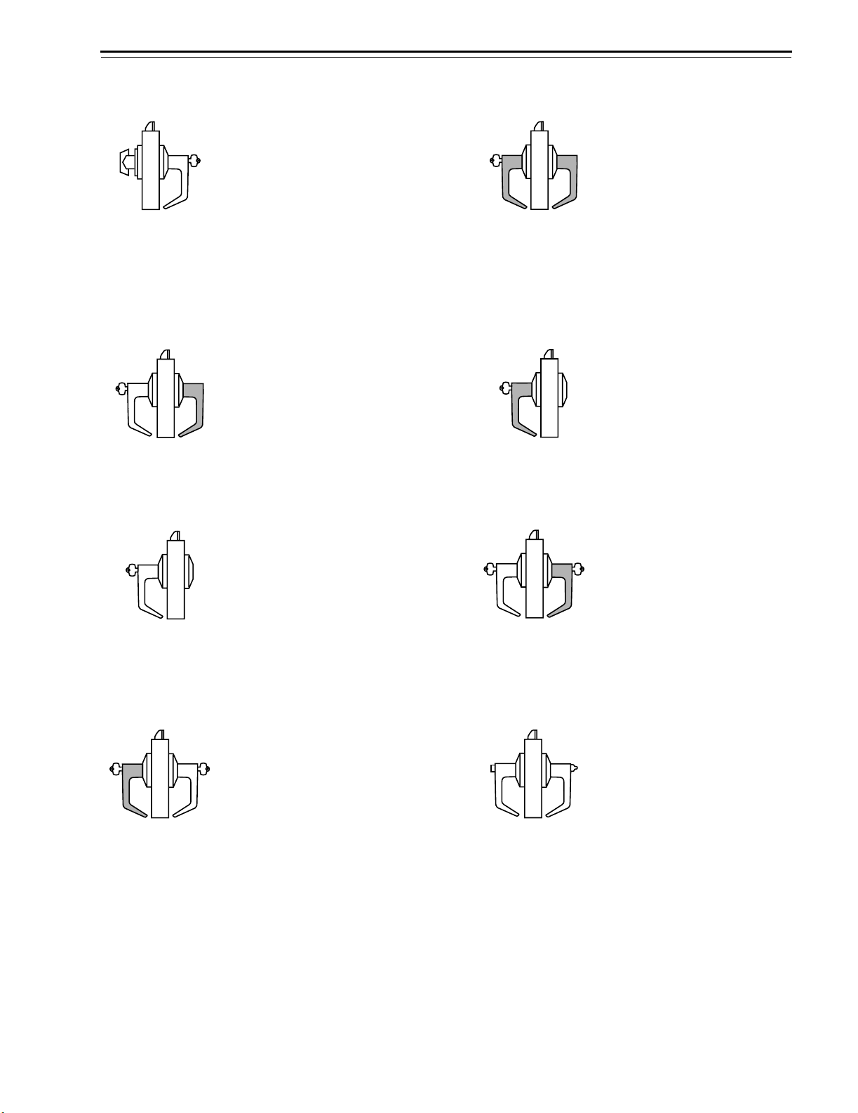
the function name.
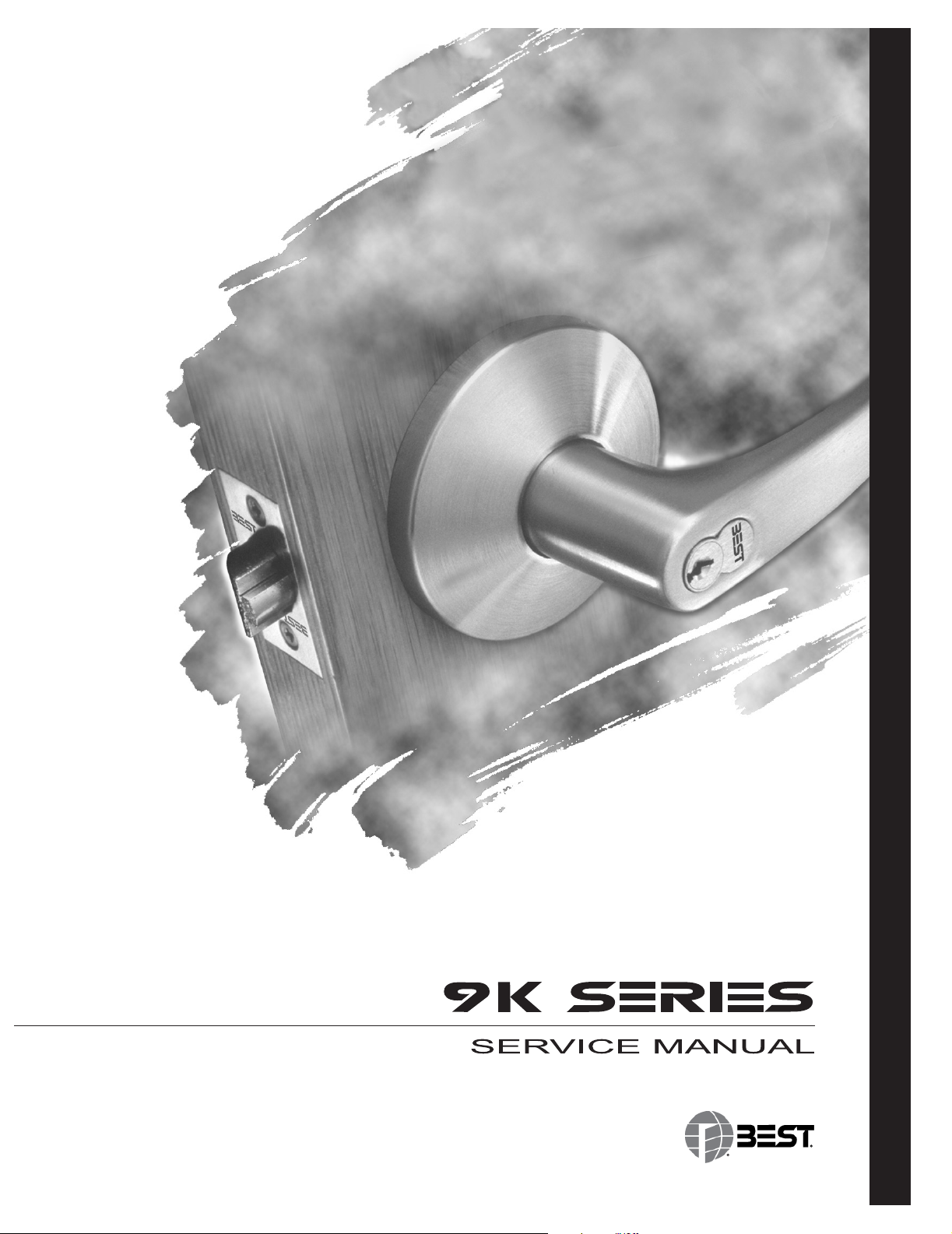
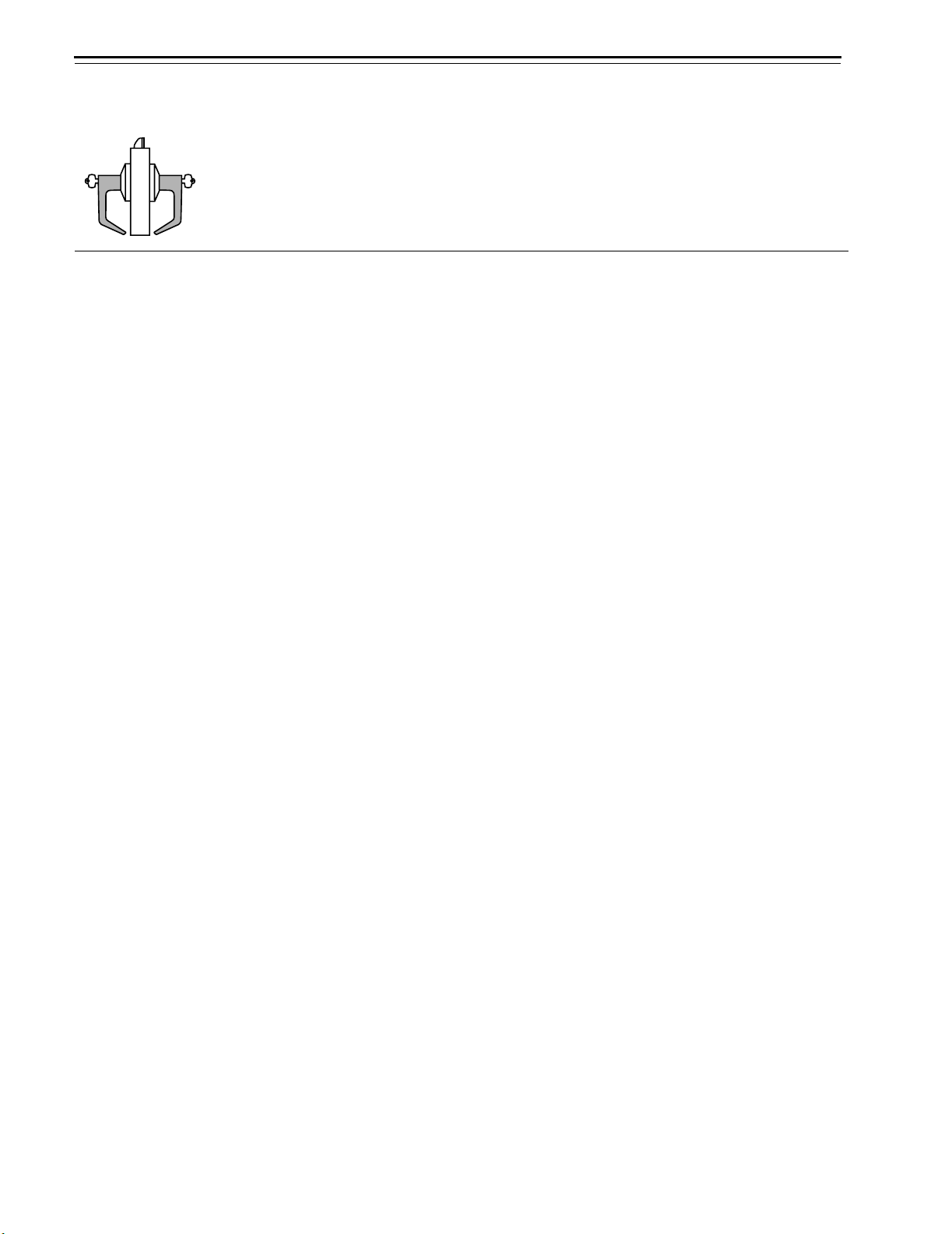
Latch
Shading indicates
that the lever is fixed.
OutsideInside
View looking down
at the top of the door
Figure 2.1 Understanding function drawings
2–2 9K Series Service Manual
Functions and Parts Lists
Single-keyed
functions
The following lists describe how the latchbolt, outside lever, and inside
lever operate for each single-keyed 9K function.
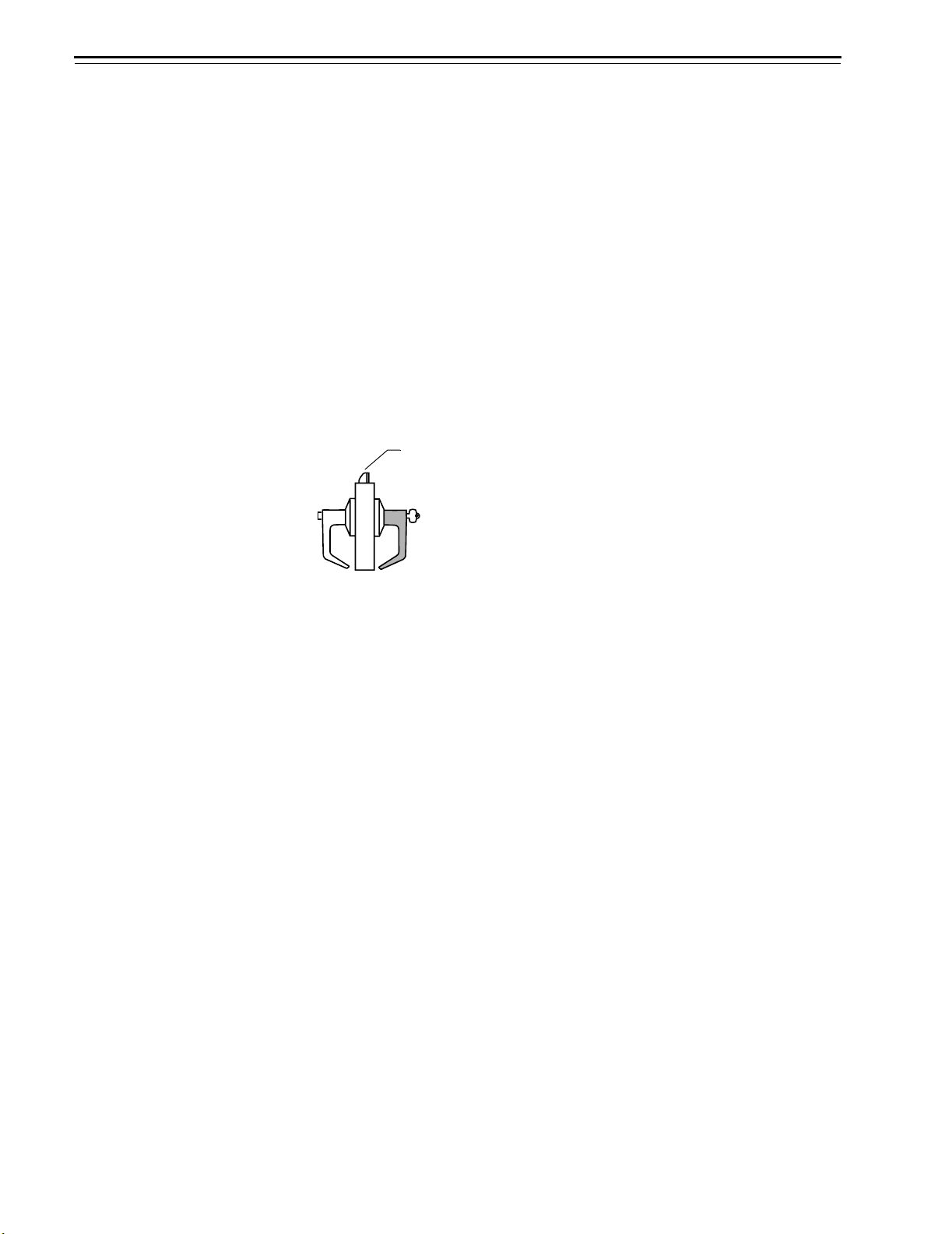
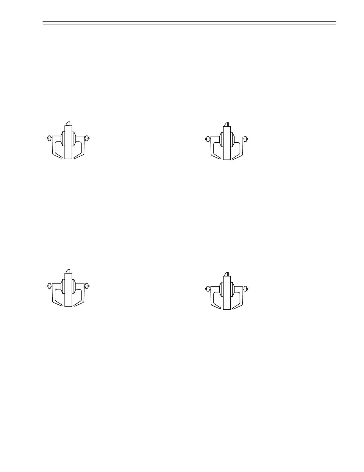
AB–Entrance (ANSI F109) D–Storeroom (ANSI F86)
Latchbolt operated by:
■ inside lever
■ outside key
■ outside lever when the inside
bu
tton is in the unlock
positi
on
ed
Outside lever locked by:
■ inside button when pushed in
■ inside button when pushed in
an
d rotated clockwise
Outside lever unlocked by:
■ inside lever when the inside
button is pushed in but not
rotated
■ outside key when the inside
button is pushed in but not
rotated
■ closing the door when the
inside button is pushed in but
not rota
ted
Inside lever is always
unlocked
Latchbolt operated by:
■ inside lever
■ outside key
Outside lever is always fixed
Inside lever is alwa
unlocked
ys
E–Service station (ANSI F92) H and HJ–Hotel guest room (ANSI F93 for H only)
Latchbolt operated by:
■ inside lever
■ outside key
■ outside lever when the inside
bu
tton is in the unlock
positi
on
ed
Outside lever locked by:
■ inside slotted button
■ inside slotted button when
pus
hed in and rota
ted
clockwise
Outside
■ inside lever
■ inside slotted button when
■ outside key
■ closing the door when the
lever unlocked by:
rot
ated counterclockwise
inside button is pushed in but
not rota
ted
Inside lever is always
unlocked
Note: For the H fu
projects an “Occupied” indicator in the outside lever
and blocks all operating keys. For the HJ function,
pushing the inside button blocks all operating keys.
Latchbolt operated by:
■ inside lever
■ outside key when the inside
button is in th
e unlock
ed
position
■ special emergency key after
the core is
removed with th
control key
O
utside lever is always fixed
Key block feature released
by:
■ inside lever
■ closing the door
Inside lever is alwa
ys
unlocked
nction, pushing the inside button
e
9K Series Service Manual 2–3
Functions and Parts Lists
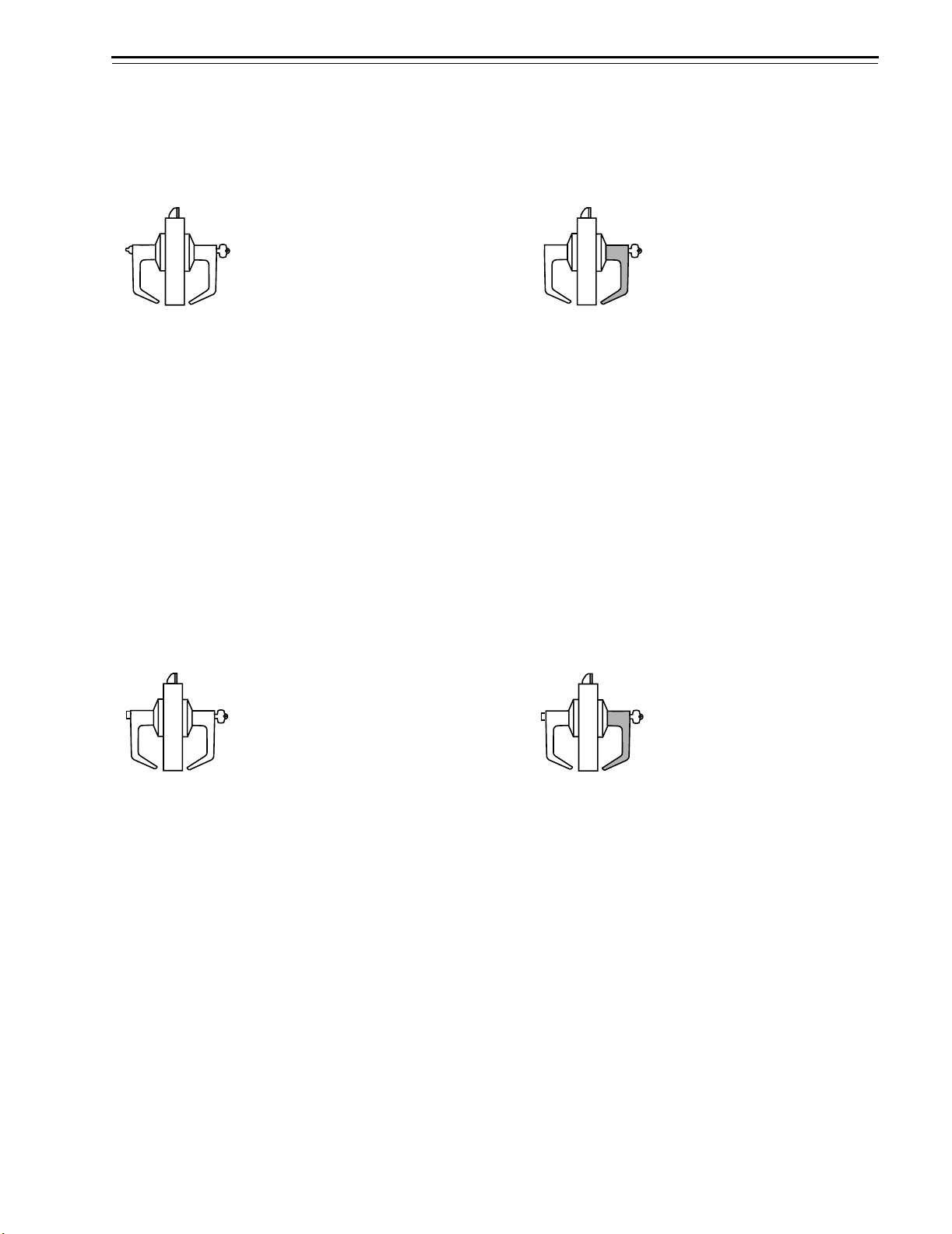
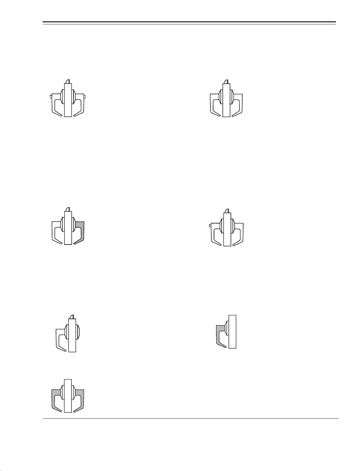
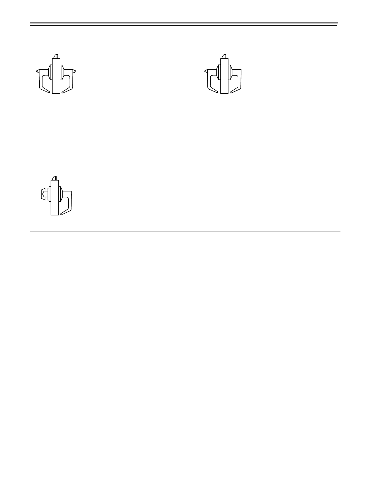
R–Classroom (ANSI F84) T–Dormitory (ANSI F90)
Latchbolt operated by:
■ inside lever
■ outside key
■ outside lever when not locked
Outside lever locked by:
■ outside key
Outside lever unlocked by:
■ outside key
Inside lever is always
unlocked
Latchbolt operated by:
■ inside lever
■ outside lever when not locked
Outside lever locked by:
■ inside button
■ outside key
Outside lever unlocked by:
■ inside lever when the inside
■ outside key
■ closing the door when the
Inside lever is always
unlocked
button is pushed in
inside button is pushed in
2–4 9K Series Service Manual
Functions and Parts Lists
Double-keyed
functions
The following lists describe how the latchbolt, outside lever, and inside
lever operate for each double-keyed 9K function.
Warning:
Locks that secure both sides of the door are controlled by
®
building codes and the Life Safety Code
. In an emergency exit
situation, failure to quickly unlock the door could be hazardous,
or even fatal.
C–Corridor (ANSI F88) G–Storeroom (ANSI F91)
Latchbolt operated by:
■ inside lever
■ outside key
■ outside lever when not locked
Outside lever locked by:
■ inside key
Outside lever unlocked by:
■ inside key
Inside lever is always
unlocked
Note: Turning the key in either the inside or outside
lever locks or unlocks both sides.
Latchbolt operated by:
■ inside lever when not locked
■ outside lever when not locked
Outside lever locked by:
■ inside key
■ outside key
Outside lever unlocked by:
■ inside key
■ outside key
Inside lever locked by:
■ inside key
■ outside key
Inside lever unlocked by:
■ inside key
■ outside key
IN–Intruder S–Communicating (ANSI F80)
Latchbolt operated by:
■ inside lever
■ outside lever when not locked
Outside lever locked by:
■ inside key
■ outside key
Outside lever unlocked by:
■ inside key
■ outside key
Inside lever is always
unlocked
Note: Turning the key in either lever locks or
unlocks that lever independently.
Latchbolt operated by:
■ inside key
■ inside lever when not locked
■ outside key
■ outside lever when not locked
Outside lever locked by:
■ outside key
Outside lever unlocked by:
■ outside key
Inside lever locked by:
■ inside key
Inside lever unlocked by:
■ inside key
9K Series Service Manual 2–5
Functions and Parts Lists
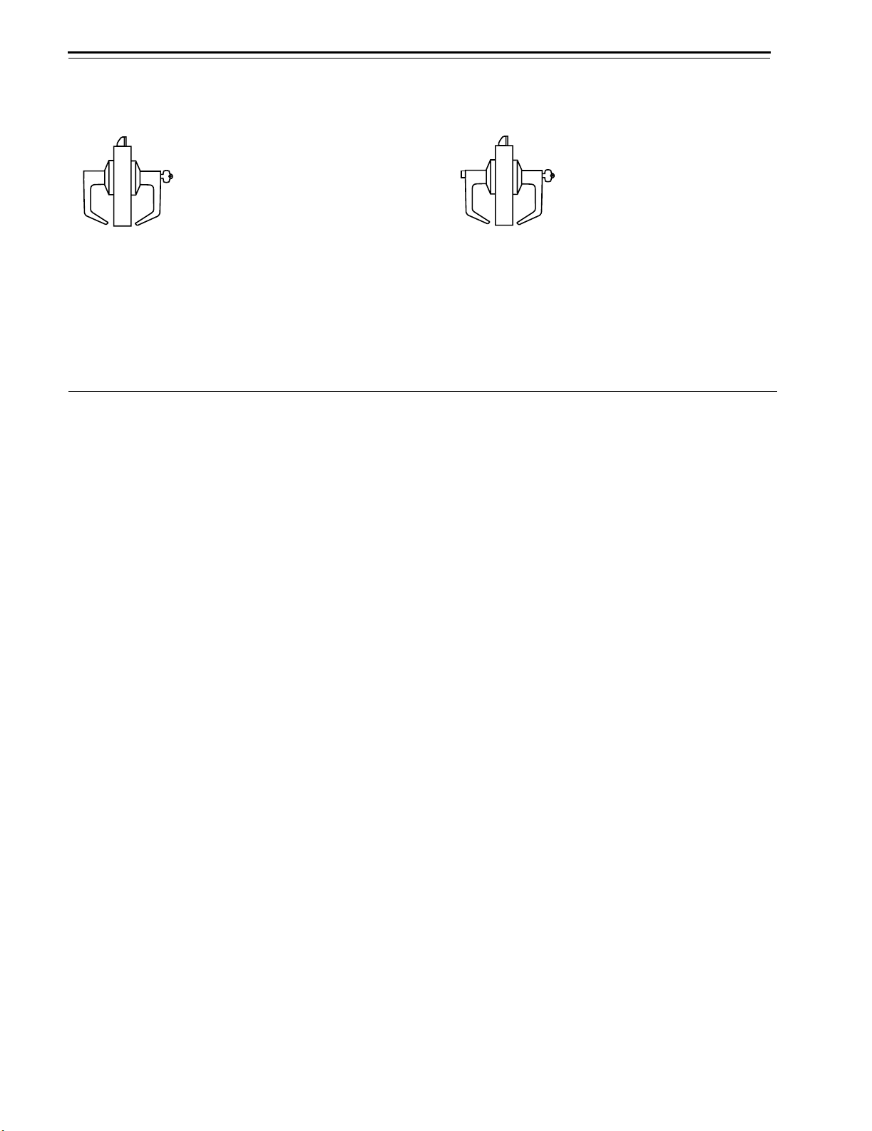
W–Institutional (ANSI F87)
Latchbolt operated by:
■ inside key
■ outside key
Outside
Inside lever is always fixed
lever is always fixed
2–6 9K Series Service Manual
Functions and Parts Lists
Non-keyed
functions
The following lists describe how the latchbolt, outside lever, and inside
lever operate for each non-keyed 9K function.
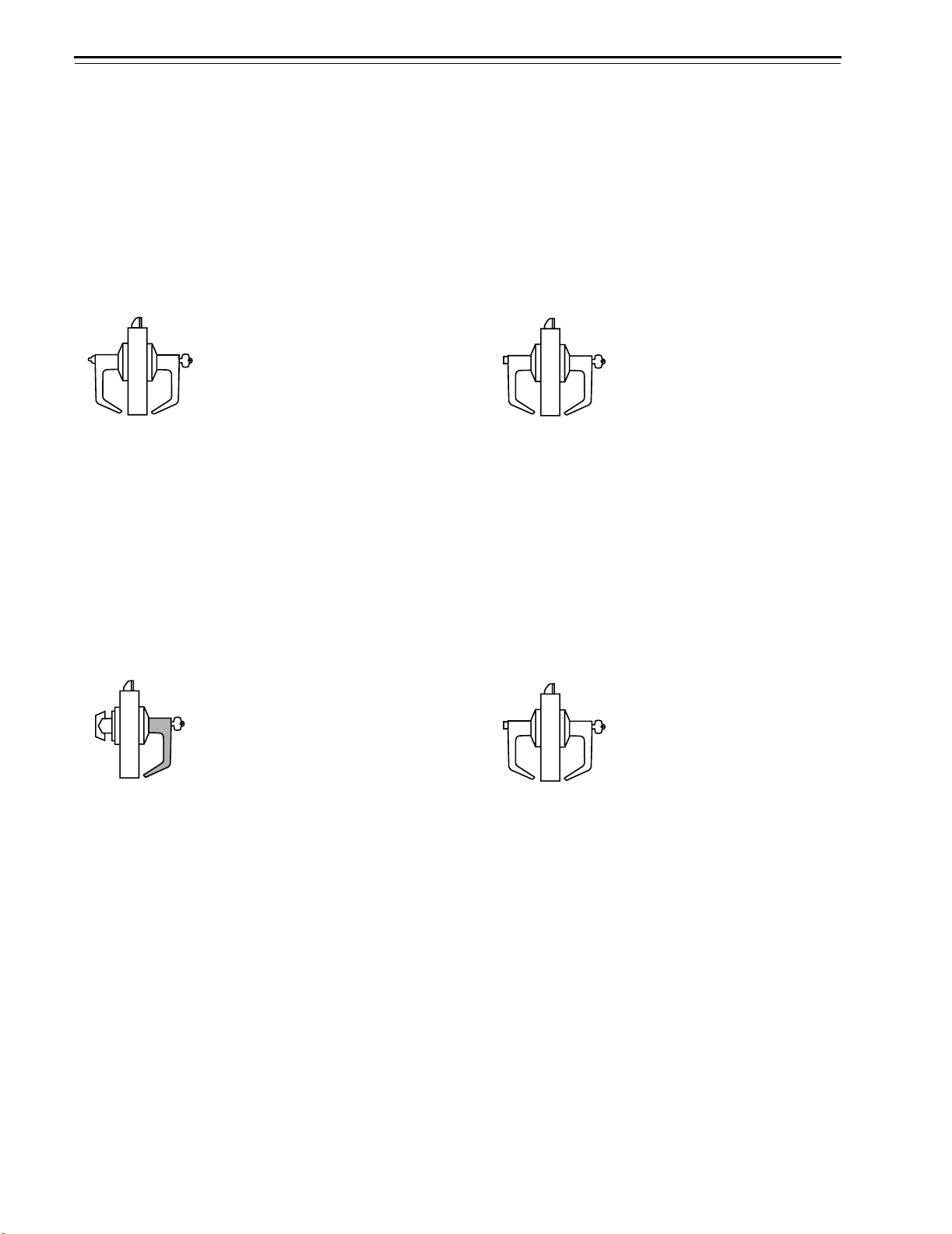
L–Privacy (ANSI F76) N–Passage (ANSI F75)
Latchbolt operated by:
■ inside lever
■ outside lever when the inside
bu
tton is in the unlock
positi
on
ed
Outside lever locked by:
■ inside button
Outside lever unlocked by:
■ inside lever
■ outside slotted button when
pus
hed in and rota
coun
terclockwise
■ closing the door
ted
Inside lever is always
unlocked
Latchbolt operated by:
■ inside lever
■ outside lever
O
unlocked
Inside lever is
unlocked
NX–Exit (ANSI F89) P–Patio (ANSI F77)
Latchbolt operated by:
■ inside lever
Outside lever is always fixed
Inside lever is always
unlocked
Latchbolt operated by:
■ inside lever
■ outside lever when the inside
O
■ inside button
Outside lever unlocked by:
■ inside lever
■ closing the door
Inside lever is alwa
unlocked
utside lever is al
alwa
ways
ys
button is in the unlock
position
utside lever locked by:
ys
ed
Y–Exit 1DT–Single dummy trim
Latchbolt operated by:
■ inside lever
Inside lever is always
unlocked
This lock is a single, surface
mounted lever for an inactive
door or a non-latching door.
2DT–Double dummy trim
This lock is a through-bolt
mounted pair of matching levers
for an inactive door or a
non-latching door.
9K Series Service Manual 2–7
Functions and Parts Lists
Special
functions
The following lists describe how the latchbolt, outside lever, and inside
lever operate for each special 9K function.
Warning:
Locks that secure both sides of the door are controlled by
building codes and the Life Safety Code
®
situation, failure to quickly unlock the door could be hazardous,
or even fatal.
A–Dormitory or storeroom lock (ANSI F81) B–Office (ANSI F82)
Latchbolt operated by:
■ inside lever
■ outside key
■ outside lever when the inside
bu
tton is in the unlock
positi
on
Outside lever locked by:
■ inside button
Outside lever unlocked by:
■ inside button
Inside lever is always
unlocked
e: Inside button must be rotated
Not
counterclockwise to unlock the outside lever.
ed
Note: Inside button is released by turning the key in
the outside lever or rotating the inside lever. Closing
the door does not release the inside button.
. In an emergency exit
Latchbolt operated by:
■ inside lever
■ outside key
■ outside lever when the inside
button is in the unlock
position
O
utside lever locked by:
■ inside button
Outside lever unlocked by:
■ inside lever
■ outside key
Inside lever is alwa
unlocked
ed
ys
DZ–Closet or storeroom EA–Entrance or Office
Latchbolt operated by:
■ inside turn knob
■ outside key
Outside lever is always fixed
Inside turn knob
is always
unlocked
e: Turning the slotted button keeps the outside
Not
lever locked until the button is turned back.
Latch
■ inside lever
■ outside key
■ outside lever when the inside
O
■ inside button
■ inside button when pushed in
Outside lever unlocked by:
■ inside lever
■ inside button when rotated
■ outside key
Inside lever is alwa
unlocked
bolt operated by:
button is in the unlock
position
utside lever locked by:
a
nd rotated clockwise
counterclockwise
ys
ed
2–8 9K Series Service Manual
RZ–Closet or storeroom XD–Special
Latchbolt operated by:
■ inside turn knob
■ outside key
■ outside lever when not locked
Outside lever locked by:
■ outside key
Outside lever unlocked by:
■ outside key
Inside turn knob
is always
unlocked
XR–Special YD–Exit
Latchbolt operated by:
■ inside key
■ inside lever when not locked
Outside lever is always fixed
Inside lever locked by:
■ inside key
Inside lever unlocked by:
■ inside key
Functions and Parts Lists
Lat
chbolt operated by:
■ inside key
Outside lever is always fixed
Inside lever is always fixed
Latchbolt operated by:
■ inside key
Inside lever is always fixed
YR–Special DR–Special
Latchbolt operated by:
■ inside key
■ inside lever when not locked
Inside lever locked by:
■ inside key
Inside lever unlocked by:
■ inside key
RD–Special LL–Hospital privacy
Latchbolt operated by:
■ inside key
■ outside key
■ outside lever when not locked
Outside lever locked by:
■ outside key
Outside lever unlocked by:
■ outside key
Inside lever is always fixed
Latchbolt operated by:
■ inside key
■ inside lever when not locked
■ outside key
Outside lever is always fixed
Inside lever locked by:
■ inside key
Inside lever unlocked by:
■ inside key
Latchbolt operated by:
■ inside lever
■ outside lever when not locked
Outside lever locked by:
■ inside button when pushed in
Outside lever unlocked by:
■ inside lever
■ outside button when pushed
in and rota
ted
counterclockwise
■ closing the door
Inside lever is alwa
ys
unlocked
9K Series Service Manual 2–9
Functions and Parts Lists
M–Communicating (ANSI F78) Q–Exit (ANSI F83)
Latchbolt operated by:
■ inside lever when not locked
■ outside lever when not locked
Outside lever locked by:
■ inside button
Outside lever unlocked by:
■ inside button
Inside lever locked by:
■ outside button
Inside lever unlocked by:
■ outside button
e: Do not use this function for rooms that have
Not
no other entrance.
Z–Closet latch
Latchbolt operated by:
■ inside turn knob
■ outside lever
Outside lever is alwa
unlocked
Inside tu
rn knob
unlocked
ys
is always
Latchbolt operated by:
■ inside lever
■ outside lever when not locked
Outside lever locked by:
■ inside button
Outside lever unlocked by:
■ inside button
Inside lever is alwa
ys
unlocked
2–10 9K Series Service Manual
Functions and Parts Lists
Electrified
cylindrical
The following lists describe how the latchbolt, outside lever, and inside
lever operate for each electrified 9K function.
functions
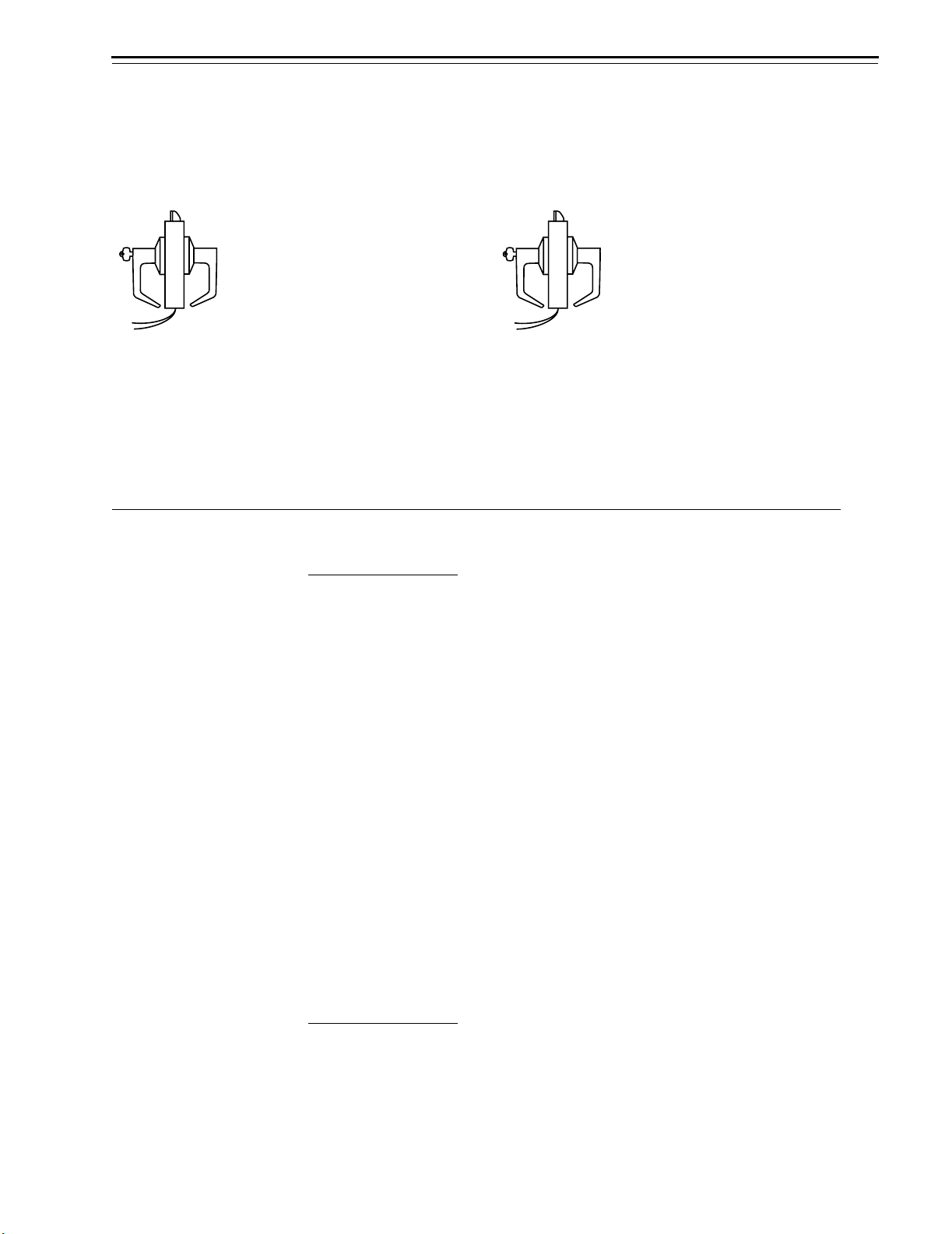
DEL–Electrically Locked–Fail Safe DEU–Electrically Unlocked–Fail Secure
Latchbolt operated by:
■ inside lever
■ outside lever when electric
enoid
is remo
ved from the
power
sol
■ outside key
Outside lever locked by:
■ applying 24 VDC to the
solenoid; remains locked only
whil
e power continues to
pplied
a
Outside lever unlocked by:
■ removing 24 VDC from the
enoid
sol
Inside lever is always
unlocked
be
Latchbolt operated by:
■ inside lever
■ outside lever when electric
power is applied to the
sol
enoid
■ outside key
Outside lever locked by:
■ removing 24 VDC from the
sol
enoid
Outside lever unlocked by:
■ applying 24 VDC to the
solenoid; remains unlocked
only whil
to be
e power continue
applied
Inside lever is always
unlocked
Functions
by ANSI
designation
ANSI no. Function
F75 N
F76 L
F77 P
F78 M
F80 S
F81 A
F82 B
F83 Q
F84 R
F86 D
F87 W
F88 C
F89 NX
F90 T
F91 G
F92 E
F93 H
F109 AB
s
9K Series Service Manual 2–11
2–12 9K Series Service Manual
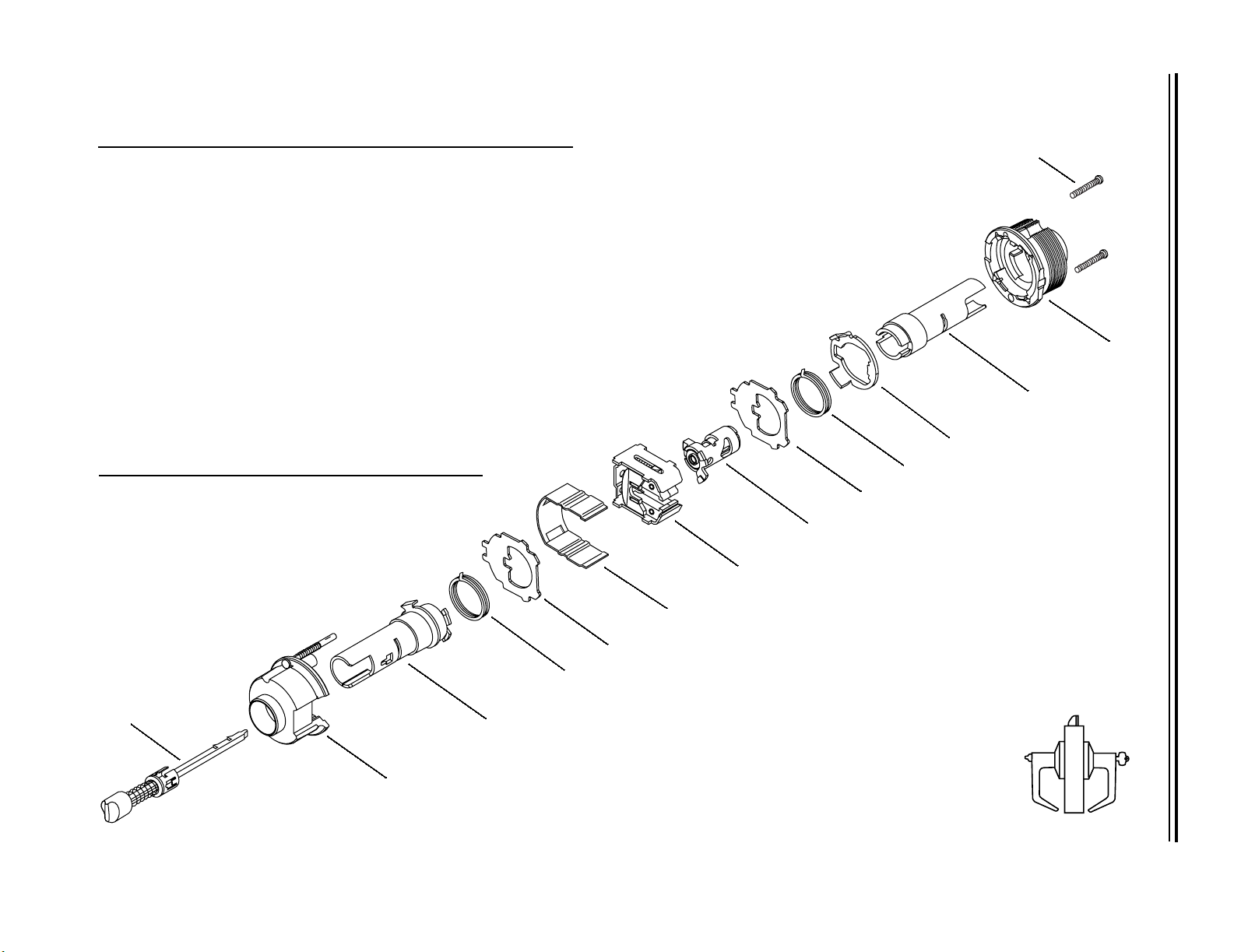
STANDARD FUNCTIONS
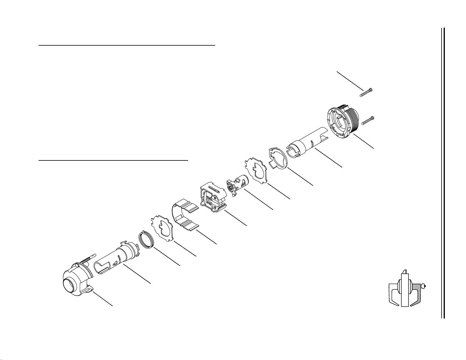
AB FUNCTION CHASSIS—ENTRANCE LOCK (ANSI F109)
Functions and Parts Lists
Item Part No. Qty. Description
1 B55692 1 Turn button assembly
2 A55685 1 Inside hub and locking pin assembly
3 B55610 1 Non-keyed sleeve and driver assembly
4 B55518 2 Lever return spring
5 B55504 2 Thrust plate
6 B54172 1 Chassis cover
7 B54886 1
8 A55673 1
9 C55515 1
10
not shown
not shown
11
not shown
12 A55505 2 Chassis screw
a. Specify finish.
b. For use with non-interchangeable cores.
c. For use with large format interchangeable cores.
A55687
A55725
A88631
D55571
D5600311
Retractor assembly with long catchplate
Key release cam assembly
Spring drive plate
1
Keyed sleeve assembly or
Keyed sleeve assembly
1
1
Keyed sleeve assembly
Outside hub or
Outside hub, lost motion
a
b
c
12
11
10
9
4
5
8
7
Outside
1
2
Inside
Figure 2.2 AB function exploded diagram
6
5
4
3
AB

9K Series Service Manual 2–13
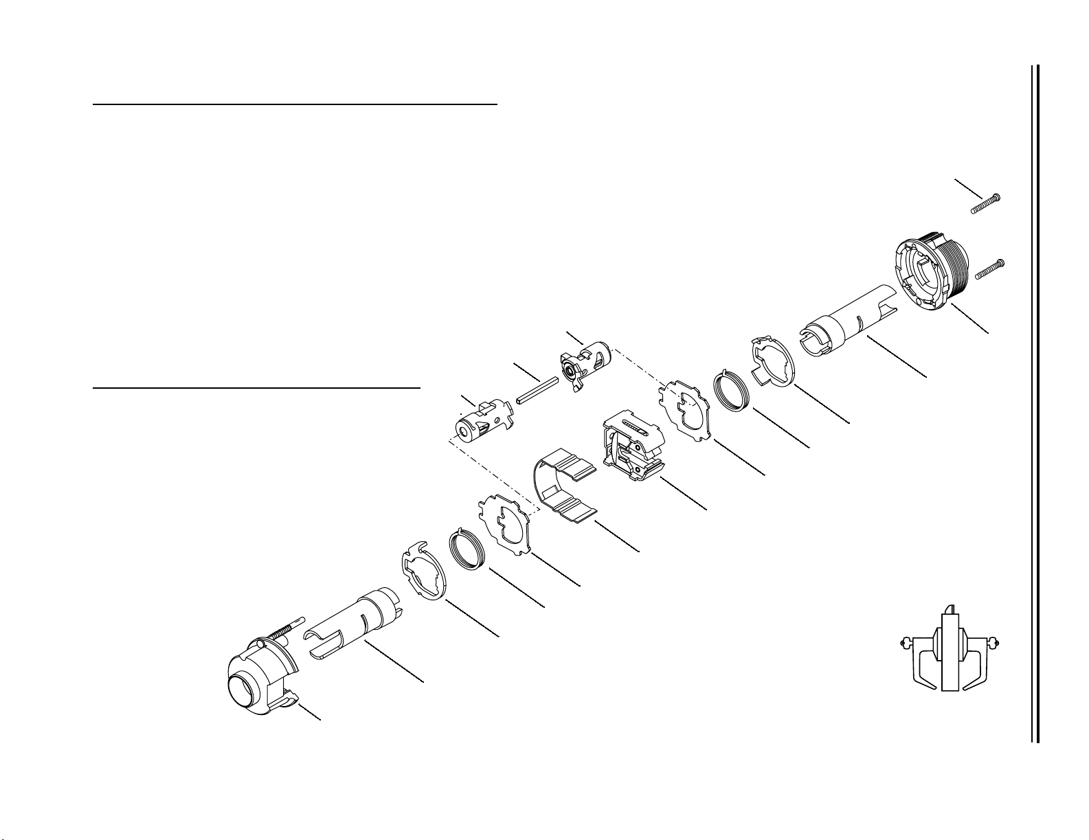
C FUNCTION CHASSIS—CORRIDOR LOCK (ANSI F88)
Item Part No. Qty. Description
1
not shown
2
not shown
not shown
3 C55515 2 Spring drive plate
4 B55518 2 Lever return spring
5 B55504 2 Thrust plate
6 B54172 1 Chassis cover
7 A54190 1 Locking bar
8 B54888 1
9 A55673 1
10
not shown
not shown
11
not shown
12 A55505 2 Chassis screw
a. For use with non-interchangeable cores.
b. For use with large format interchangeable cores.
A55685
A5600811
B55700
B56024
B89839
A55687
A55725
A88631
D55571
D5600311
Inside hub and locking pin assembly or
Inside hub assembly, lost motion
Sleeve & key release cam assembly or
1
Sleeve & key release cam assembly
1
Sleeve & key release cam assembly
1
Retractor assembly without catchplate
Key release cam assembly
Keyed sleeve assembly or
1
Keyed sleeve assembly
1
Keyed sleeve assembly
1
Outside hub or
Outside hub, lost motion
a
b
a
b
12
9
7
10
3
4
5
8
11
Outside
Inside
Figure 2.3 C function exploded diagram
6
5
4
3
2
1
C
Functions and Parts Lists
2–14 9K Series Service Manual
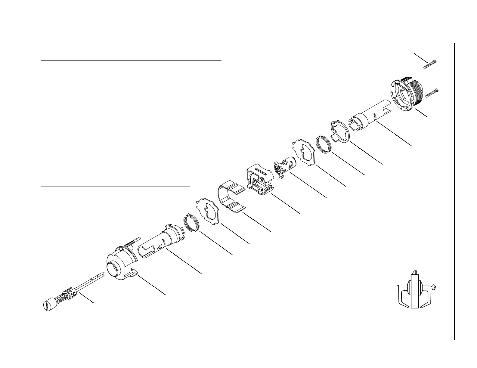
D FUNCTION CHASSIS—STOREROOM LOCK (ANSI F86)
Item Part No. Qty. Description
1 A55685 1 Inside hub and locking pin assembly
2 B55610 1 Non-keyed sleeve and driver assembly
3 B55518 1 Lever return spring
4 B55504 2 Thrust plate
5 B54172 1 Chassis cover
6 B54888 1 Retractor assembly without catchplate
7 A55675 1 Key release cam assembly
8 C55515 1
9
not shown
not shown
10
not shown
11 A55505 2 Chassis screw
A55687
A55725
A88631
D55571
D5600311
Spring drive plate
Keyed sleeve assembly or
1
1
Keyed sleeve assembly
1
Keyed sleeve assembly
Outside hub or
Outside hub, lost motion
Functions and Parts Lists
11
a
b
10
a. For use with non-interchangeable cores
b. For use with large format interchangeable cores.
Inside
1
Figure 2.4 D function exploded diagram
9
Outside
8
4
7
6
5
4
3
2
D
9K Series Service Manual 2–15
E FUNCTION CHASSIS—SERVICE STATION LOCK (ANSI F92)
Item Part No. Qty. Description
1 B55694 1 Slotted button assembly
2 A55685 1 Inside hub and locking pin assembly
3 B55610 1 Non-keyed sleeve and driver assembly
4 B55518 2 Lever return spring
5 B55504 2 Thrust plate
6 B54172 1 Chassis cover
7 B54886 1
8 A55673 1
9 C55515 1
10
not shown
not shown
11
not shown
12 A55505 2 Chassis screw
a. Specify finish.
b. For use with non-interchangeable cores.
c. For use with large format interchangeable cores.
A55687
A55725
A88631
D55571
D5600311
Retractor assembly with long catchplate
Key release cam assembly
Spring drive plate
Keyed sleeve assembly or
1
Keyed sleeve assembly
1
1
Keyed sleeve assembly
Outside hub or
Outside hub, lost motion
a
b
c
12
11
10
9
4
5
8
7
Outside
1
Inside
Figure 2.5 E function exploded diagram
6
5
4
Functions and Parts Lists
3
E
2
2–16 9K Series Service Manual
G FUNCTION CHASSIS—STOREROOM LOCK (ANSI F91)
Item Part No. Qty. Description
1
not shown
2
not shown
not shown
3 C55515 2 Spring drive plate
4 B55518 2 Lever return spring
5 B55504 2 Thrust plate
6 B54172 1 Chassis cover
7 A55676 2 Key release cam assembly
8 B54888 1 Retractor assembly without catchplate
9 A54195 1 Locking bar
10
not shown
11 A55505 2 Chassis screw
a. For use with non-interchangeable cores.
b. For use with large format interchangeable cores.
A55685
A5600811
A55687
A55725
A88631
D55571
D5600311
Inside hub and locking pin assembly or
Inside hub assembly, lost motion
Keyed sleeve assembly or
2
2
Keyed sleeve assembly
Keyed sleeve assembly
2
Outside hub or
Outside hub, lost motion
a
b
Functions and Parts Lists
11
7
9
2
7
3
4
Outside
10
Inside
1
Figure 2.6 G function exploded diagram
5
8
6
5
4
G
3
2

9K Series Service Manual 2–17
H FUNCTION CHASSIS—HOTEL GUEST ROOM LOCK WITH INDICATOR (ANSI F93)
HJ FUNCTION CHASSIS—HOTEL GUEST ROOM LOCK WITHOUT INDICATOR
a
Item
1 B55693 1 Push button assembly
2 A55685 1 Inside hub and locking pin assembly
3 B55610 1 Non-keyed sleeve and driver assembly
4 B55518 1 Lever return spring
5 B55504 2 Thrust plate
6 B54172 1 Chassis cover
7 B54886 1 Retractor assembly with long catchplate
8 A55677 1 Key release cam assembly
9 C55515 1 Spring drive plate
10 A55687 1 Keyed sleeve assembly
11
not shown
12 A55505 2 Chassis screw
a. These functions require a special throw member. See page 2–54.
b. Specify finish.
Part No. Qty. Description
D55571
D5600311
Outside hub or
Outside hub, lost motion
b
8
12
11
10
Outside
9
5
1
Inside
Figure 2.7 H/HJ function exploded diagram
7
6
5
4
3
H, HJ
2
Functions and Parts Lists

2–18 9K Series Service Manual
L FUNCTION CHASSIS—PRIVACY LOCK (ANSI F76)
Functions and Parts Lists
Item Part No. Qty. Description
1 B55693 1 Push button assembly
2 A55685 1 Inside hub and locking pin assembly
3 B55610 1 Non-keyed sleeve and driver assembly
4 B55518 2 Lever return spring
5 B55504 2 Thrust plate
6 B54172 1 Chassis cover
7 B54886 1 Retractor assembly with long catchplate
8 A55673 1 Key release cam assembly
9 C55515 1 Spring drive plate
10 A55701 1 Keyed sleeve assembly
11
not shown
12 A54745 1 Button release assembly
13 A55505 2 Chassis screw
a. Specify finish.
D55571
D5600311
Outside hub or
Outside hub, lost motion
a
12
9
4
5
8
7
13
11
10
Outside
1
Inside
Figure 2.8 L function exploded diagram
6
5
4
3
L
2
 Loading...