

Best 6K Service Manual


CREDITS/COPYRIGHT
©
2001-2002 Best Lock Corporation dba Best Access Systems. All rights reserved.
Printed in the United States of America.
Information in this document is subject to change without notice and does not
represent a commitment on the part of Best Access Systems. The software described in
this document are furnished under a license agreement or nondisclosure agreement.
This publication is intended to be an accurate description and set of instructions
pertaining to its subject matter. However, as with any publication of this complexity,
errors or omissions are possible. Please call your BEST distributor or Best Access
Systems at (317) 849-2250 if you see any errors or have any questions. No part of this
manual and/or databases may be reproduced or transmitted in any form or by any
means, electronic or mechanical, including photocopying, recording, or information
storage and retrieval systems, for any purpose, without the express written permission
of Best Access Systems.
This document is distributed as is, without warranty of any kind, either express or
implied, respecting the contents of this book, including but not limited to implied
warranties for the publication’s quality, performance, merchantability, or fitness for any
particular purpose. Neither Best Access Systems, nor its dealers or distributors shall be
liable to the user or any other person or entity with respect to any liability, loss, or
damage caused or alleged to be caused directly or indirectly by this publication.
The Best Access Systems logo is a registered trademark of Best Lock Corporation.
Written and designed by Best Access Systems and Avalon Group, Inc., Indianapolis,
Indiana.
T56080 Rev B 1798060 ER-7991-6 May 2002

6K Series Service Manual iii
CONTENTS
FIGURES V
GETTING STARTED 1–1
Introduction 1–1
Certifications and standards 1–1
Documentation package 1–1
Technical support 1–2
Support services 1–2
Telephone technical support 1–2
FUNCTIONS AND PARTS LISTS 2–1
Function descriptions 2–2
Single-keyed functions 2–2
Non-keyed functions 2–4
Special functions 2–5
Functions by ANSI designation 2–5
Exploded diagrams and parts lists 2–6
AB function—entrance lock (ANSI F109) 2–6
B function—entrance lock (ANSI F82) 2–7
D function—storeroom lock (ANSI F86) 2–8
E function—service station lock (ANSI F92) 2–9
L function—privacy lock (ANSI F76) 2–10
LL function—hospital privacy 2–11
N function—passage lock (ANSI F75) 2–12
P function—patio lock (ANSI F77) 2–13
R function—classroom lock (ANSI F84) 2–14
Y function—exit lock 2–15
Function conversion 2–16

Contents
iv 6K Series Service Manual
Trim parts 2–17
Strikes and strike boxes 2–17
Roses and rose liners 2–18
Knobs and throw member 2–19
Dummy trim 2–20
Latches and latch tube sleeve 2–21
Tools 2–22
SERVICE AND MAINTENANCE 3–1
Replacing parts 3–2
Replacing the core and throw member 3–2
Replacing the knob 3–3
Replacing the button assembly 3–4
Replacing the bearing 3–6
Replacing the inside rose and rose liner 3–7
Replacing the outside rose and liner assembly 3–8
Replacing the lock chassis assembly 3–9
Lubricating the core 3–10
Aligning the chassis and trim 3–11
Troubleshooting 3–12
INSTALLATION INSTRUCTIONS A–1
I
NDEX B–1

6K Series Service Manual v
FIGURES
FUNCTIONS AND PARTS LISTS
Understanding function drawings 2–2
AB function exploded diagram 2–6
B function exploded diagram 2–7
D function exploded diagram 2–8
E function exploded diagram 2–9
L function exploded diagram 2–10
LL function exploded diagram 2–11
N function exploded diagram 2–12
P function exploded diagram 2–13
R function exploded diagram 2–14
Y function exploded diagram 2–15
Strikes and strike boxes 2–17
Roses and rose liners 2–18
Knobs 2–19
Throw member and spacer 2–19
Dummy trim parts 2–20
Latches 2–21
Latch tube sleeve 2–21
Installation tools 2–22
Boring jig kit 2–23
SERVICE AND MAINTENANCE
Removing and reinstalling the core 3–2
Removing the knob 3–3

Figures
vi 6K Series Service Manual
Reinstalling the non-keyed knob 3–3
Reinstalling the keyed knob 3–4
Removing the button assembly 3–4
Reinstalling the outside button assembly 3–5
Reinstalling the inside button assembly 3–5
Removing the bearing 3–6
Reinstalling the bearing 3–6
Removing the inside rose and rose liner 3–7
Reinstalling the inside rose and rose liner 3–8
Removing the outside rose and liner assembly 3–8
Reinstalling the outside rose and liner assembly 3–9
Engaging the retractor in the latch 3–10
Engaging the retractor in the latch 3–11

6K Series Service Manual 1–1
1
GETTING STARTED
INTRODUCTION
The 6K Series Service Manual contains essential
information to help you maintain your 6K Series
Lock.
CERTIFICATIONS AND STANDARDS
■ The locks comply with ANSI A156.2, Series 4000
Grade 2 standards.
■ The locks are listed by Underwriter’s Laboratories
for use on 3 Hr., A label single swinging doors
(4´ x 8´).
■ The 8KS3 strike fits the standard door frame
cutout as specified in ANSI A115.2.
DOCUMENTATION PACKAGE
The following documentation is available to help you
with the installation, start-up, and maintenance of
your 6K Series Lock.
The installation and assembly instructions also can
be ordered separately:
Document Title Doc. No.
Installation Instructions for 6K Cylindrical Locks T56061

Getting Started
1–2 6K Series Service Manual
The templates required for lock installations also can be ordered
separately:
TECHNICAL SUPPORT
Support
services
When you have a question about the 6K Series Lock, your first resource
for help is the 6K Series Service Manual. If you cannot find a
satisfactory answer, contact your local BEST Representative.
Telephone
technical
support
A factory-trained Certified Product Specialist (CPS) is available in your
area whenever you need help. Before you call, however, please make
sure that the product is in your immediate vicinity, and that you are
prepared to give the following information:
■ what happened and what you were doing when the problem arose
■ what you have done so far to correct the problem.
Best Access Systems Representatives provide telephone technical
support for all 6K Series products. You may locate the representative
nearest you by calling (317) 849-2250 Monday through Friday, between
7:00 a.m. and 4:00 p.m. eastern standard time; or visit the web page,
www.BestAccess.com.
Document Title Doc. No.
K01 Template for Door and Frame Preparation for
62K Locks with Small (STK) Strike
T56050
K07 Template for Door and Frame Preparation for
62K Locks with Large (S3) Strike
T56051
K08 Template for Door and Frame Preparation for
63K, 73KC, 83K & 93K Locks with Small (STK) Strike
T56052
K09 Template for Door and Frame Preparation for
63K, 73KC, 83K & 93K Locks with Large (S3) Strike
T56053
K10 Template for Door and Frame Preparation
for 64K, 84K & 94K Locks with Small (STK) Strike
T56054
K11 Template for Door and Frame Preparation
for 64K, 84K, 94K Locks with Large (S3) Strike
T56055
K12 Template for Door and Frame Preparation 65K,
85K & 95K Locks with Small (STK) Strike
T56056
K13 Template for Door and Frame Preparation for
65K, 85K & 95K Locks with Large (S3) Strike
T56057

6K Series Service Manual 2–1
2
FUNCTIONS AND PARTS LISTS
The following pages contain function descriptions
for all 6K Series Locks. This chapter also includes
exploded diagrams that show all field serviceable
mechanical parts, diagrams of trim and other
miscellaneous parts, and function conversion
information.
Functions and Parts Lists
2–2 6K Series Service Manual
FUNCTION DESCRIPTIONS
This section includes function descriptions grouped by the following
function types:
■ single-keyed (page 2–2)
■ non-keyed (page 2–4)
■ special (page 2–5)
■ ANSI designation (page 2–5).
Note: If the function is ANSI defined, the ANSI designation appears by
the function name.
Single-keyed
functions
The following lists describe how the latchbolt, outside knob, and inside
knob operate for each single-keyed 6K function.
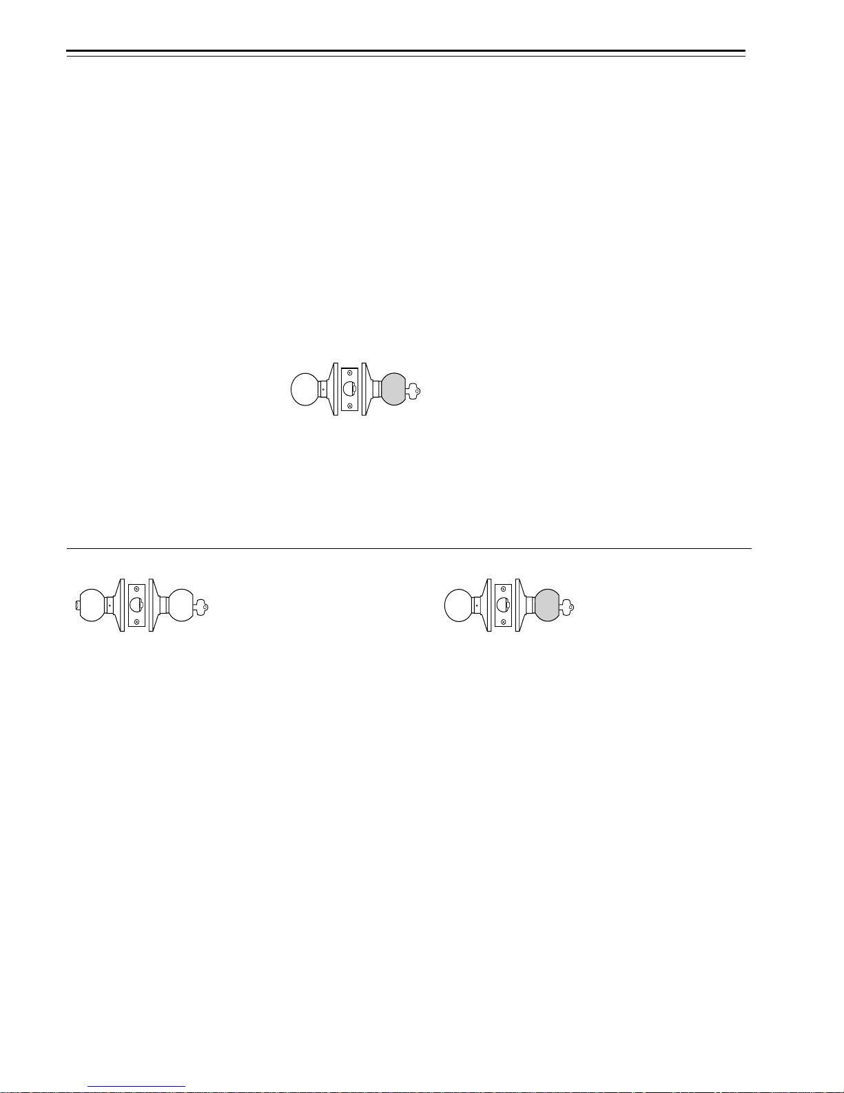
Figure 2.1 Understanding function drawings
OutsideInside
Shading indicates
that the knob is fixed.
AB–Entrance (ANSI F109) D–Storeroom (ANSI F86)
Latchbolt operated by:
■ inside knob
■ outside key
■ outside knob when the
inside button is in the
unlocked position
Outside knob locked by:
■ inside button when
pushed in
■ inside button when
pushed in and rotated
clockwise
Outside knob unlocked by:
■ inside knob when the
inside button is pushed
in but not rotated
■ outside key when the
inside button is pushed
in but not rotated
■ closing the door when
the inside button is
pushed in but not
rotated
Inside knob is always
unlocked
Latchbolt operated by:
■ inside knob
■ outside key
Outside knob is always
fixed
Inside knob is always
unlocked

Functions and Parts Lists
6K Series Service Manual 2–3
E–Service station (ANSI F92) R–Classroom (ANSI F84)
Latchbolt operated by:
■ inside knob
■ outside key
■ outside knob when the
inside button is in the
unlocked position
Outside knob locked by:
■ inside slotted button
■ inside slotted button
when pushed in and
rotated clockwise
Outside knob unlocked by:
■ inside knob
■ inside slotted button
when rotated
counterclockwise
■ outside key
■ closing the door when
the inside button is
pushed in but not
rotated
Inside knob is always
unlocked
Latchbolt operated by:
■ inside knob
■ outside key
■ outside knob when not
locked
Outside knob locked by:
■ outside key
Outside knob unlocked by:
■ outside key
Inside knob is always
unlocked
Functions and Parts Lists
2–4 6K Series Service Manual
Non-keyed
functions
The following lists describe how the latchbolt, outside knob, and inside
knob operate for each non-keyed 6K function.
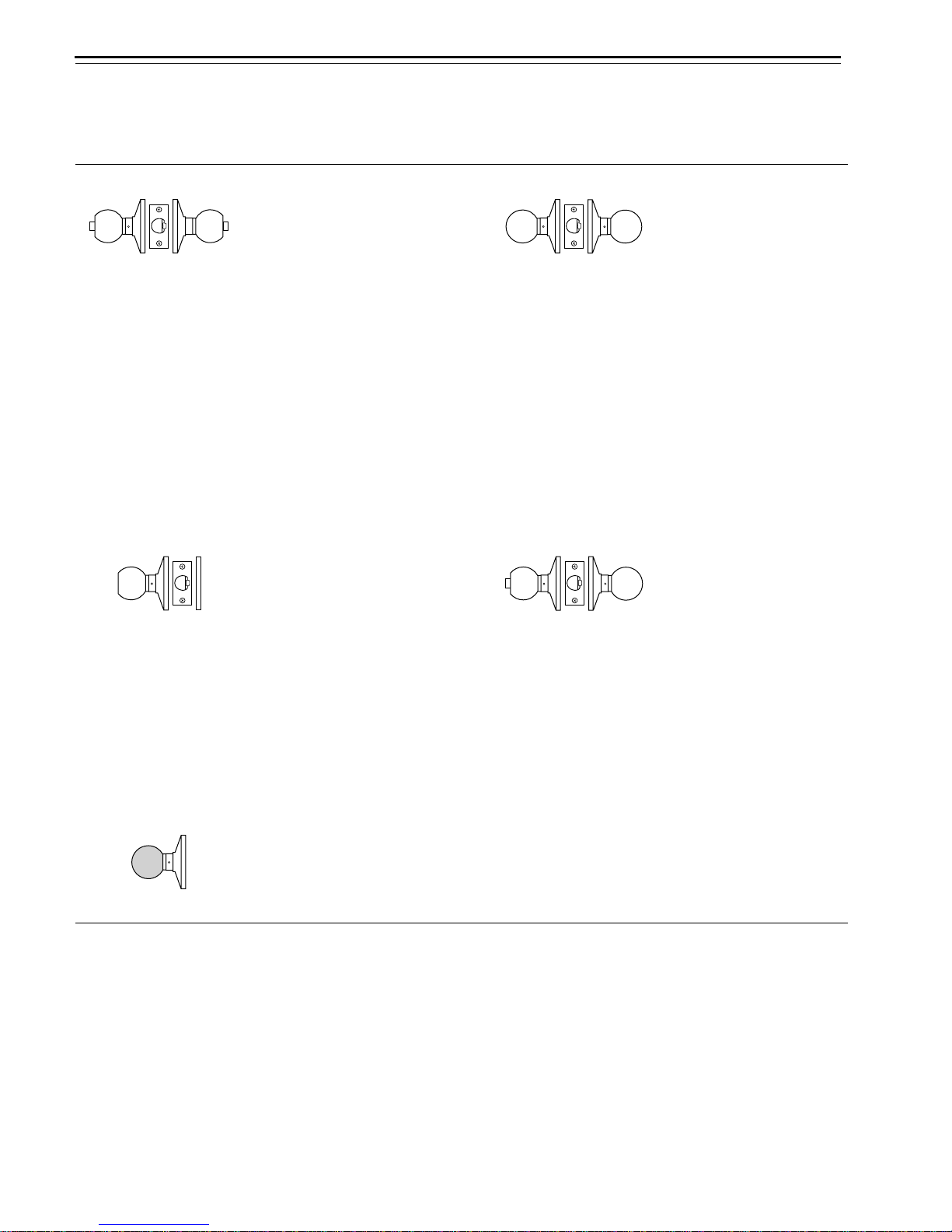
L–Privacy (ANSI F76) N–Passage (ANSI F75)
Latchbolt operated by:
■ inside knob
■ outside knob when the
inside button is in the
unlocked position
Outside knob locked by:
■ inside button
Outside knob unlocked by:
■ inside knob
■ outside slotted button
when pushed in and
rotated counterclockwise
■ closing the door
Inside knob is always
unlocked
Latchbolt operated by:
■ inside knob
■ outside knob
Outside knob is always
unlocked
Inside knob is always
unlocked
Y–Exit P–Patio (ANSI F77)
Latchbolt operated by:
■ inside knob
Inside knob is always
unlocked
Latchbolt operated by:
■ inside knob
■ outside knob when the
inside button is in the
unlocked position
Outside knob locked by:
■ inside button
Outside knob unlocked by:
■ inside knob
■ closing the door
Inside knob is always
unlocked
1DT–Single dummy trim
This lock is a single,
surface-mounted knob for
an inactive door or a
non-latching door.

Functions and Parts Lists
6K Series Service Manual 2–5
Special functions The following lists describe how the latchbolt, outside knob, and inside
knob operate for each special 6K function.
Functions
by ANSI designation
LL–Hospital privacy B-Office
Latchbolt operated by:
■ inside knob
■ outside knob when not
locked
Outside knob locked by:
■ inside button
Outside knob unlocked by:
■ inside knob
■ outside button when
pushed in and rotated
counterclockwise
■ closing the door
Inside knob is always
unlocked
Latchbolt operated by:
■ inside knob
■ outside key
■ outside knob when the
inside button is in the
unlocked position
Outside knob locked by:
■ inside button
Outside knob unlocked by:
■ inside knob
■ outside key
Inside knob is always
unlocked
ANSI No. Function
F75 N
F76 L
F77 P
F82 B
F84 R
F86 D
F92 E
F109 AB
Func
t
ions and Par
t
s Lis
t
s
2–6 6K Series Service Manual
EXPLODED DIAGRAMS AND PARTS LISTS
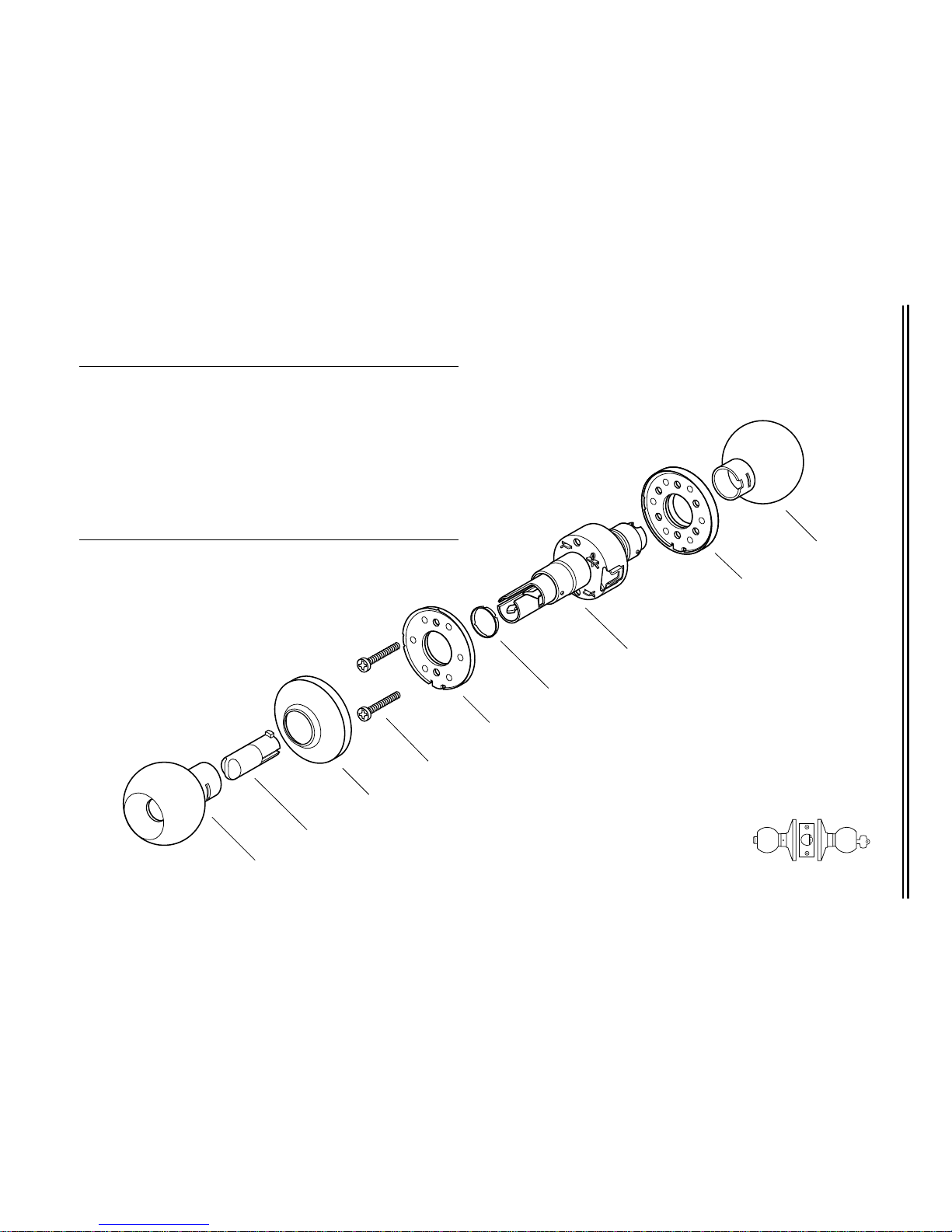
AB FUNCTION—ENTRANCE LOCK (ANSI F109)
Figure 2.2 AB function exploded diagram
1
3
4
5
6
7
8
9
Item Part No. Qty. Description
1(see page 2–19) 1 Button knob
2 A80050 1 Turn button assembly
3(see page 2–18)1Rose
4 A80041 2 Chassis screw
5(see page 2–18)1Rose liner
6 B80048 1 Bearing
7 B80105 1 AB function chassis
†
† If you are replacing a chassis, order two trim rings (part number B80004) in
addition to the chassis, and indicate the finish. The trim rings must be installed
on the chassis at the factory.
8(see page 2–18) 1 Rose and rose liner assembly
9(see page 2–19)1Keyed knob
Inside
Outside
2
AB
Func
t
ions and Par
t
s Lis
t
s
6K Series Service Manual 2–7
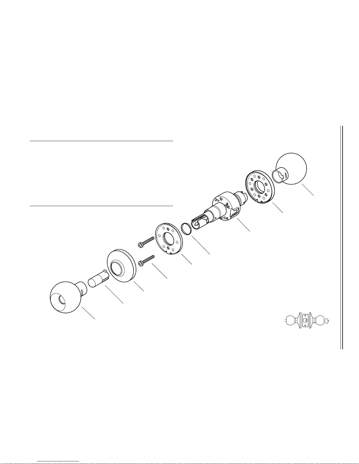
B FUNCTION—ENTRANCE LOCK (ANSI F82)
Figure 2.3 B function exploded diagram
1
3
4
5
6
7
8
9
Item Part No. Qty. Description
1(see page 2–19) 1 Button knob
2 A80052 1 Push button assembly
3(see page 2–18)1Rose
4 A80041 2 Chassis screw
5(see page 2–18)1Rose liner
6 B80048 1 Bearing
7 B80105 1 AB function chassis
†
† If you are replacing a chassis, order two trim rings (part number B80004) in
addition to the chassis, and indicate the finish. The trim rings must be installed
on the chassis at the factory.
8(see page 2–18) 1 Rose and rose liner assembly
9(see page 2–19)1Keyed knob
Inside
Outside
2
B
 Loading...