

Page 1
Installation Instructions
for 48H & 49H Mortise Locks
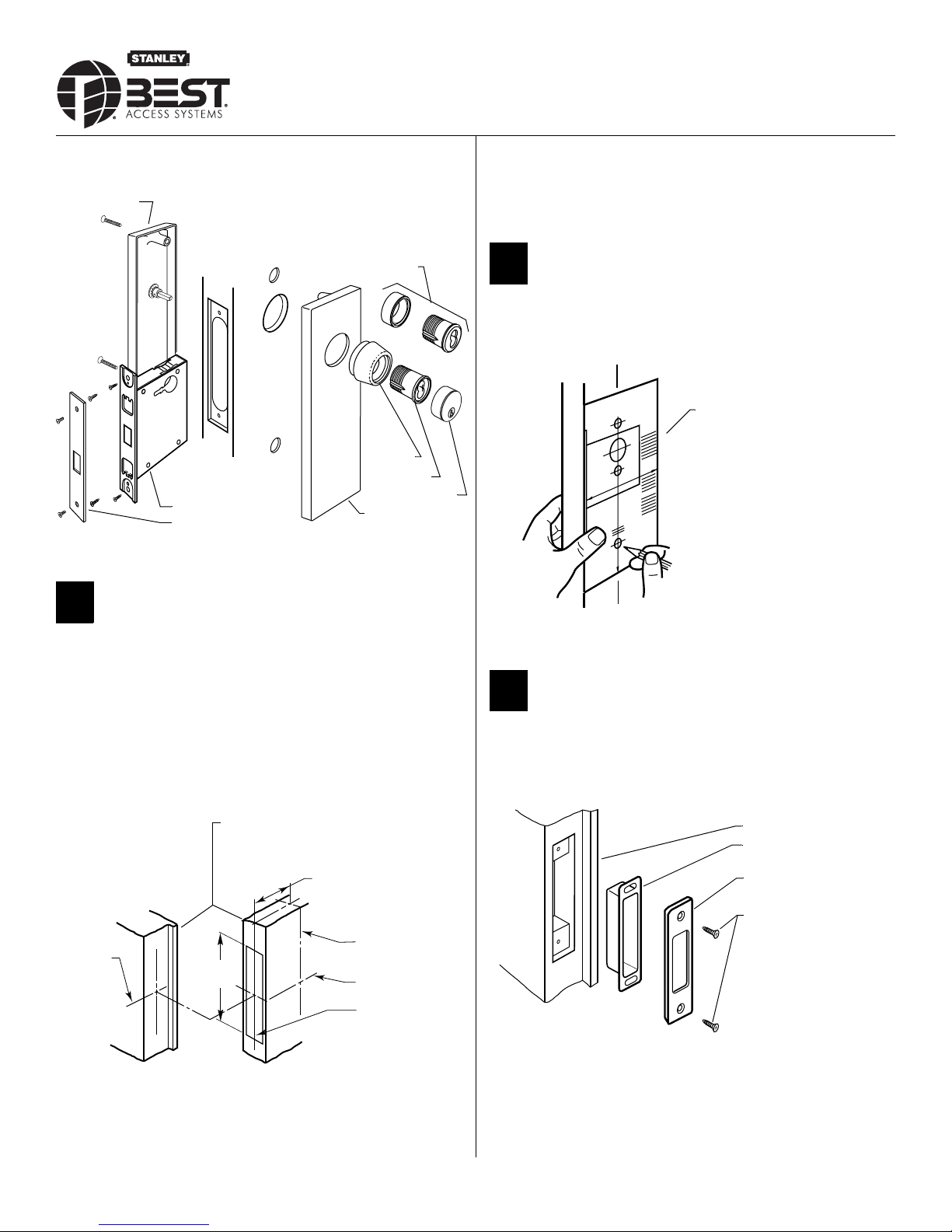
Overview
49H inside trim
Mortise lock
Faceplate
Figure 1 48H and 49H Mortise Lock overview diagram
48H Trim
49H Ring
49H Cylinder
49H Cylinder face
49H Outside
escutcheon
2 Mark the vertical centerline of the lock on the door edge.
3 Mark the vertical centerline of the lock on both sides of the door as
measured from the vertical centerline on the door’s edge.
4 Mark the horizontal centerline of the strike on the door jamb in line
with the centerline of the lock.
2 Mark drill points
1 Cut the H18 template along the dotted line and align the horizontal
and vertical arrows to the marked centerlines on the door.
H18 template
1 Mark centerlines
Caution: If you use hollow metal doors, decide whether the
doors are reinforced enough to support the lock. If the door
reinforcement is not adequate, consult the door manufacturer
about proper reinforcement.
Note: Prepare the door according to ANSI A115.1 before using these
instructions.
1 Mark the horizontal centerline of the lock on both sides of the door
and on the door’s edge.
Door to jamb gap: 1/16” to 3/16”
2 3/4” backset
Vertical center-
Centerline
of strike
line of lock
Horizontal centerof lock
Vertical centerline of door’s edge
Figure 3 Marking the drill points with the template
2 Tape the template onto the door.
3 Install strike
1 Using the H18 template, mortise the jamb and install the strike and
strike box. See Installation Specifications, Template H17 for dimen
sions.
Jamb
Strike box
Strike plate
#8–32 combination
screws
Figure 4 Installing the strike box and strike
-
Figure 2 Marking the centerlines on the door
Note: BEST suggests a 38" height as measured from floor to lock centerline.
T81175/Rev – ER-7991-19 Nov 2005
BEST ACCESS SYSTEMS
a Division of Stanley Security Solutions, Inc
1
Page 2
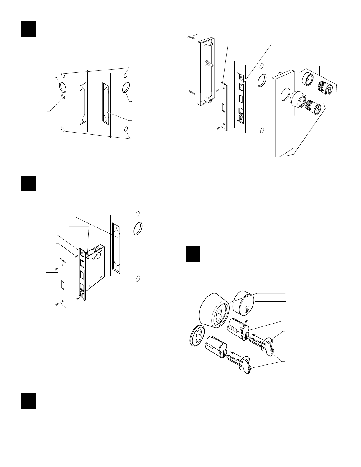
4 Mortise and drill holes
1 Mortise the door for the lock case and faceplate.
Note: Check the lock for function before drilling.
Inside cylinder
hole
‘K’ function
turn knob hole
Escutcheon
hole
Outside cylinder
hole
Mortise for lock
case & faceplate
3 Reinstall the faceplate.
Through-bolts
Faceplate
Cylinder clamp
screw (inside)
Standard cylinder
& ring (48H)
Inside Outside
Escutcheon
hole
Figure 5 Mortising and drilling holes
2 Drill only those holes required for the lock function and trim. See
Installation Specifications for hole requirements in Template H17.
5 Install mortise case
1 Remove the faceplate from the lock.
Mortise cavity
Bevel adjusting screw
Armored front
Case mounting
screws
Faceplate
High-security
cylinder, ring, &
escutcheon (49H)
Figure 7 Installing 48H or 49H trim
4 Check the lock for proper operation.
To install 49H trim:
1 Position inside and outside escutcheons opposite each other and
screw them loosely in place.
2 Put the high security cylinder(s) and ring(s) into the cylinder hole(s).
Thread the cylinder(s) into the case until the cylinder head touches
the inside rim of the ring.
3 Secure the cylinder(s) with the cylinder clamp screw(s).
4 Tighten the through-bolts.
5 Reinstall the faceplate.
7 Install core
For 5C cores only:
■ Slide the cylinder face down over the 5C core.
High security cylinder
Cylinder face
Figure 6 Installing the mortise case
2 Loosen the bevel adjusting screws on the top and bottom of the lock
case and adjust the bevel of the armored front to match the door
bevel. Retighten the screws.
For ‘R’ function only:
■ Check the cylinder and lock for proper operation.
Caution: If the handing of the ‘R’ turn knob is incorrect, you can
be locked in.
3 Install the lock into the mortise cavity.
4 Secure the lock case with the case mounting screws.
6 Install trim
To install 48H trim:
1 Install cylinder(s) and ring(s) and fasten with cylinder clamp screw(s).
2 Install thumb turn if needed.
5C core
Turn 15 degrees
Control key
Figure 8 Installing the core
For all cores:
1 Put the control key into the core (or cylinder face) and turn the key
15 degrees clockwise.
2 Adjust the throw pins if needed, then put the core (and cylinder face)
into the cylinder with the control key.
3 Turn the key 15 degrees counterclockwise and remove the key.
Note: Follow these steps to remove the core also.
BEST ACCESS SYSTEMS
a Division of Stanley Security Solutions, Inc
 Loading...