

Page 1

1
INSTALLATION
MANUAL
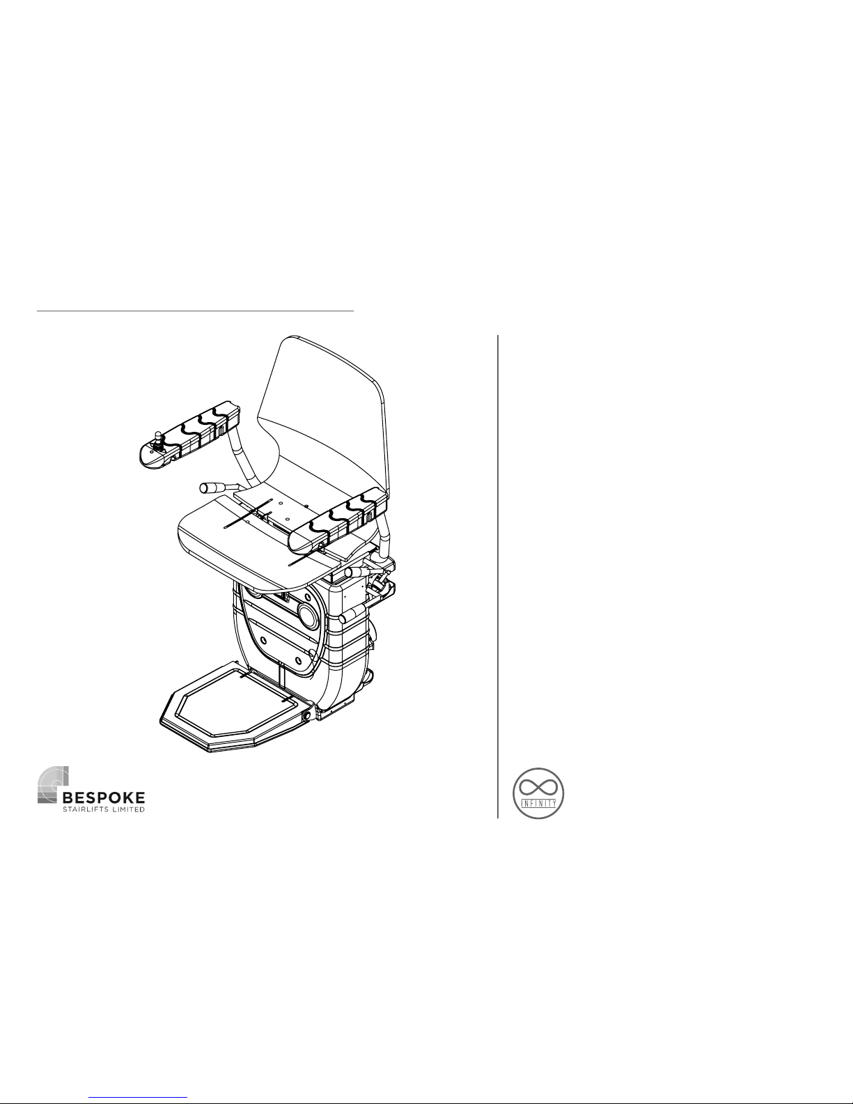
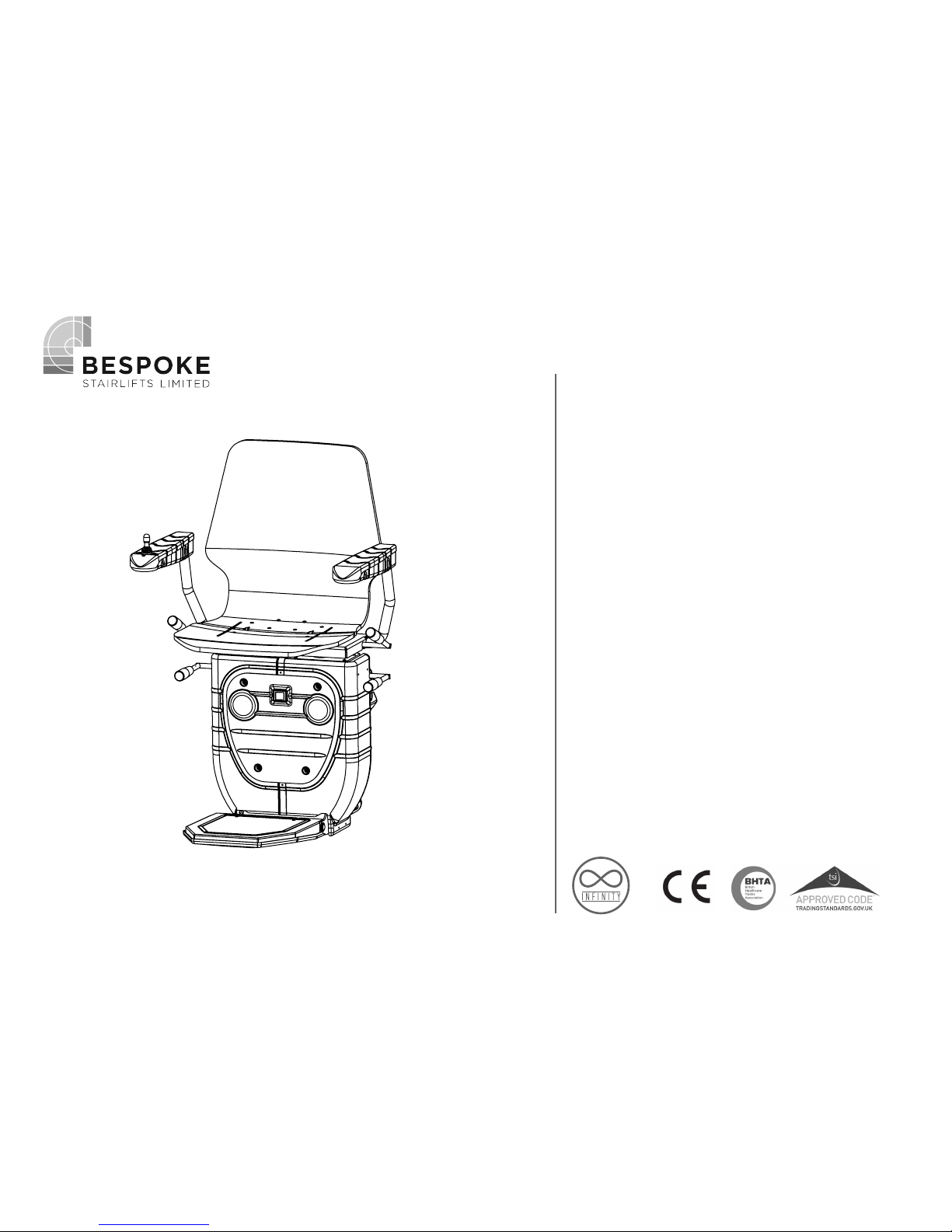
Infinity Stairlift
Rail
Carriage
Seat
Huddersfield • England
Page 2
2
The information contained within this
manual has been designed for use by
Bespoke approved engineers who have
received the appropriate product training
in the following categories,
1. Product installation.
2. Testing and commissioning.
lt is also assumed that the person
using this manual will have the basic
knowledge and skills required in both the
mechanical and electrical aspects to apply
consideration and awareness for the safety
of themselves and others involving their
work.
The contents of this manual are in the
recommended order of placement, which
forms the full installation, and
commissioning
of this standard model.
INTRODUCTION
Page 3

3
Introduction 2
Contents 3
Rail Preparation and Fixing 4-9
Carriage Preparation and Assembly 10-30
Calibrate and Program the Stairlift 31-35
Troubleshooting 36-39
Wiring Diagrams 40
Certificate of Conformity 41
Demonstration and Handover 42
Installation Tools 43
CONTENTS
Page 4
4
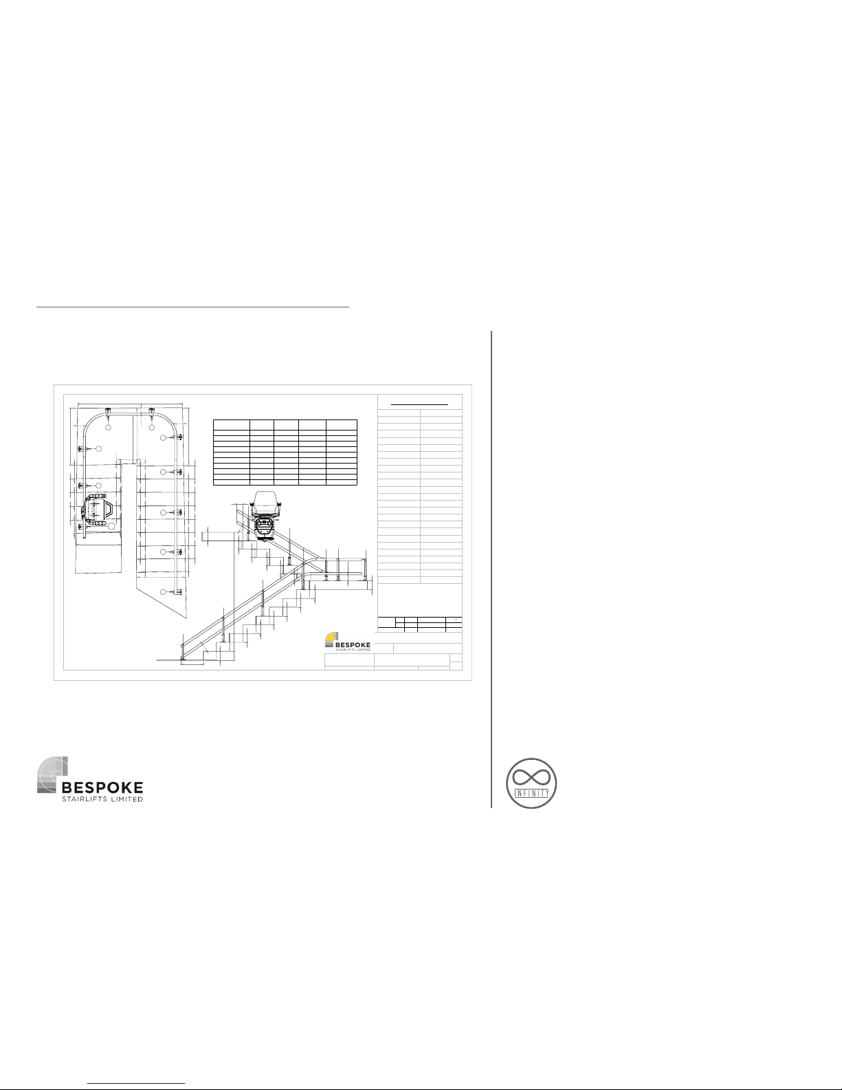
Remove packaging and protective
wrapping from rail sections.
Position rail sections on staircase as per
Installation Drawing.
Insert the leg stanchions into the relevant
bases and approximately set the height
by tightening the 3 x grub screws on each
base. (Do not tighten too much as these
will need to be adjusted later)
RAIL PREPARATION
266.3
274.7
279.4
279.1
269.9
1147
2108.8
1161.6
265.1
274
269
266.2
267.9
265.4
263
255.7
302
48.9
259.9
269.1
274.1
268.8
261.7
273.5
259.5
265.5
272.2
267.5
275.5
278.9
264.5
14.1
984.7
910.6
1117.4
967.7
719.4
122.3
106.6
125.8
Riser 1
Riser 15
1
2
3
4
5
67
8
9
10
466.7
174.9
180.9
175.3
177.1
170.3
182.8
173.8
176.9
179.1
136.9
170
165.8
166.3
163
172.5
101
100
119.8
2565.6
312.9
499.9
515.6
526.4
442.1
442
442
507.1
489.6
124.2
Base/Stanchion
Number
Type
Base
Height
Stanchion
Length
Total Height
1
New
205 ABF
280 312.87
2
New
165 450 499.87
3
New
204 450 515.62
4
New
204 450 526.37
5
New
100 400 442.06
6
New
100 400 442.04
7
New
100 400 442.04
8
New
100 400 442.02
9
New
165 450 507.07
10
New
165 450 489.59
Installation Drawing
RH EXT 180 - Standard Start and
Finish
A3
SHEET 1 OF 3
DWG:
TITLE:
Revision
DATE:
DO NOT SCALE DRAWING
UNLESS OTHERWISE SPECIFIED: DIMENSIONS ARE IN MILLIMETERS (mm)
ASSEMBLY BY:
SAGE ACCOUNT NO.
TYPE:
Model
Handing
Type
Swivel
Seat Type
Footrest
Extra Remotes
Controls
Remote Type
Region
Upholstery Colour
Surveyed By
Dispatch
Bend(s)
Rail Start
Rail Finish
Int' Landing
Int' Charge Point
Foot Covers
Rail Colour
Wall Brackets
Offset Footrest
Rail Length
Rail Sections
Bases to Kit
DRAWING BY:
1
Stairlift Specifications
10
No
7
8324.37
RAL 9010
No
No
N/A
N/A
Standard
Standard
2x90
Courier
Customer
Germany
Red
N/A
Recon
Recon
Recon
Manual
Right
BS 101
New
Standard
Square Ness
& U Bends
Vertical Height
O/B
-5/+15
I/B
-15/+5
Ride Quality
-10/+20
Upper Flights
Lower Flights
-/+2
-20/+20
-10/+20
Page 5
5
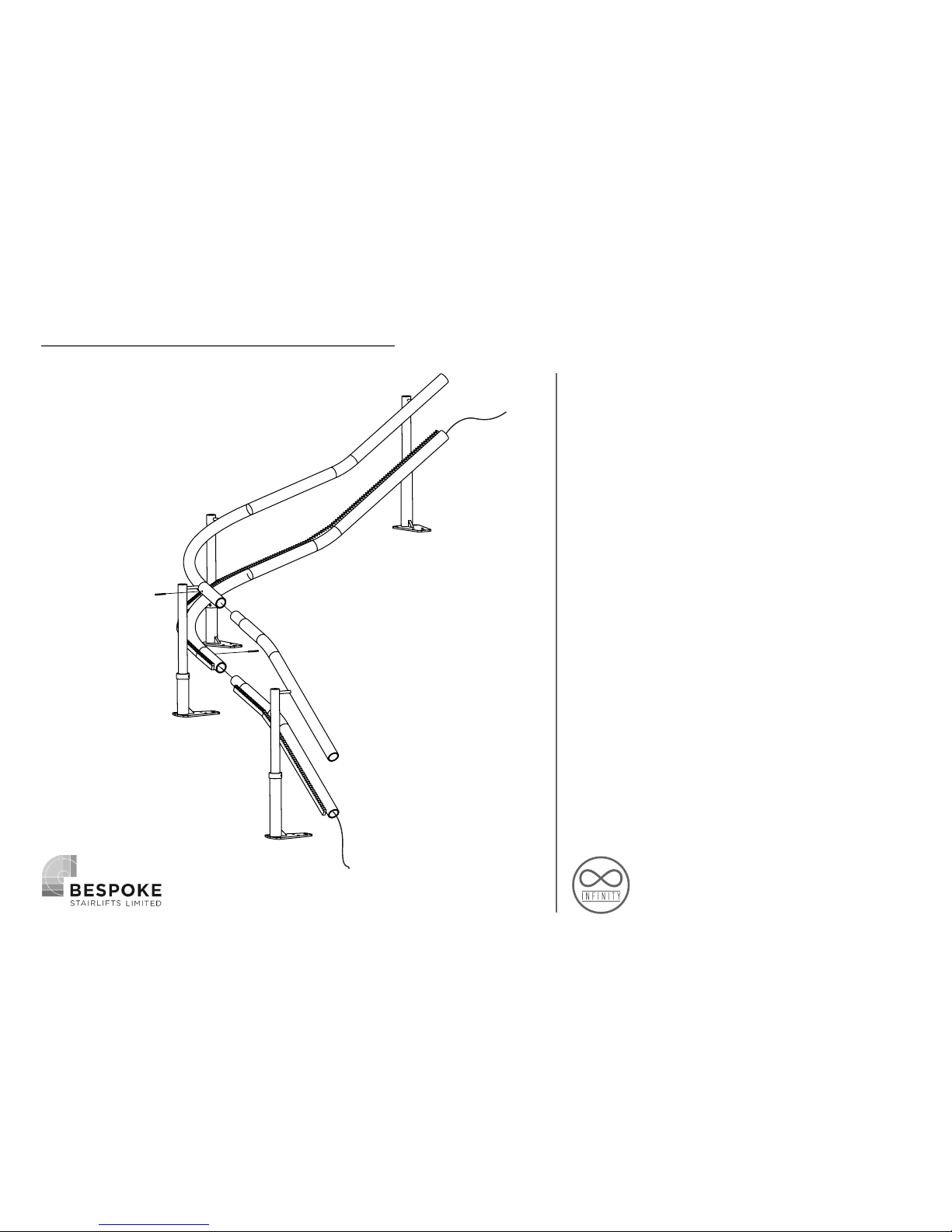
Thread 2-core cable through lower tube of
each section of rail, working from top to
bottom.
Ensure a minimum of 150mm of cable at
each end.
RAIL PREPARATION
Page 6
6
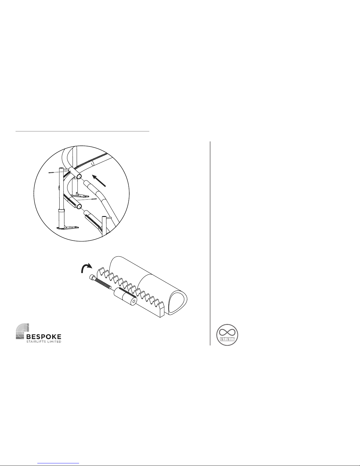
Assemble rail joints together working from
bottom to top of stairs.
Note: Offer top tubes first.
Apply grease to male part of joint.
Pins should be flush with stair side of rail.
Fit and tighten joint clamps
Using the installation drawing details:
Check top and bottom rail heights over
the corresponding steps.
Check rail angles
Check lower and upper rails are vertically
in line.
Adjust leg heights as required.
Ensure rail to wall measurements match
the Installation drawing.
RAIL FIXING
Page 7
7
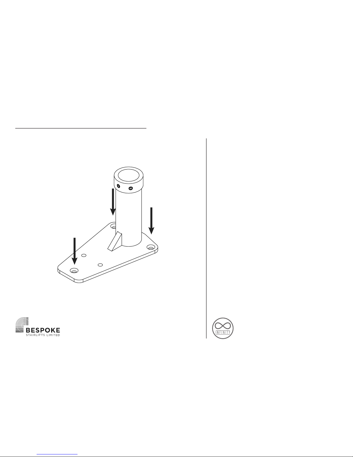
Secure plates to the staircase by the
following method:
Loosen grub screws on leg collar
Fix foot-plate with 3 screws (Figure 4)
Tighten screw to leg.
Repeat for each leg.
The following fixings are recommended:
Timber Staircase - 3 x 50mm screws.
Concrete Staircase -3 x 50mm screws & 3 x
rawlplugs.
Other Staircases - Installation
requirements must be assessed during
Survey.
BE AWARE OF HIDDEN DANGERS SUCH
AS; WIRING, PIPEWORK ETC.
RAIL FIXING
Page 8
8
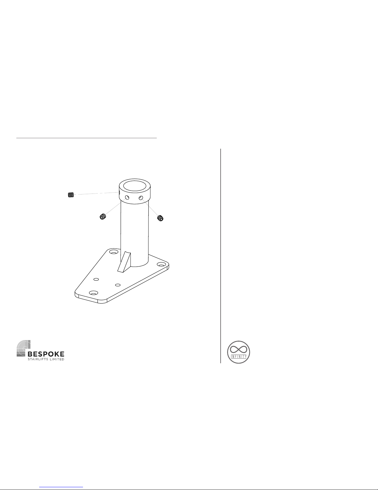
Finally ensure all rail dimensions are
in accordance with the rail installation
drawing.
Carry out any final adjustment to the
bases as required using the 3 x Grub
Screws then tighten once the rail position
is correct.
RAIL FIXING
Page 9
9
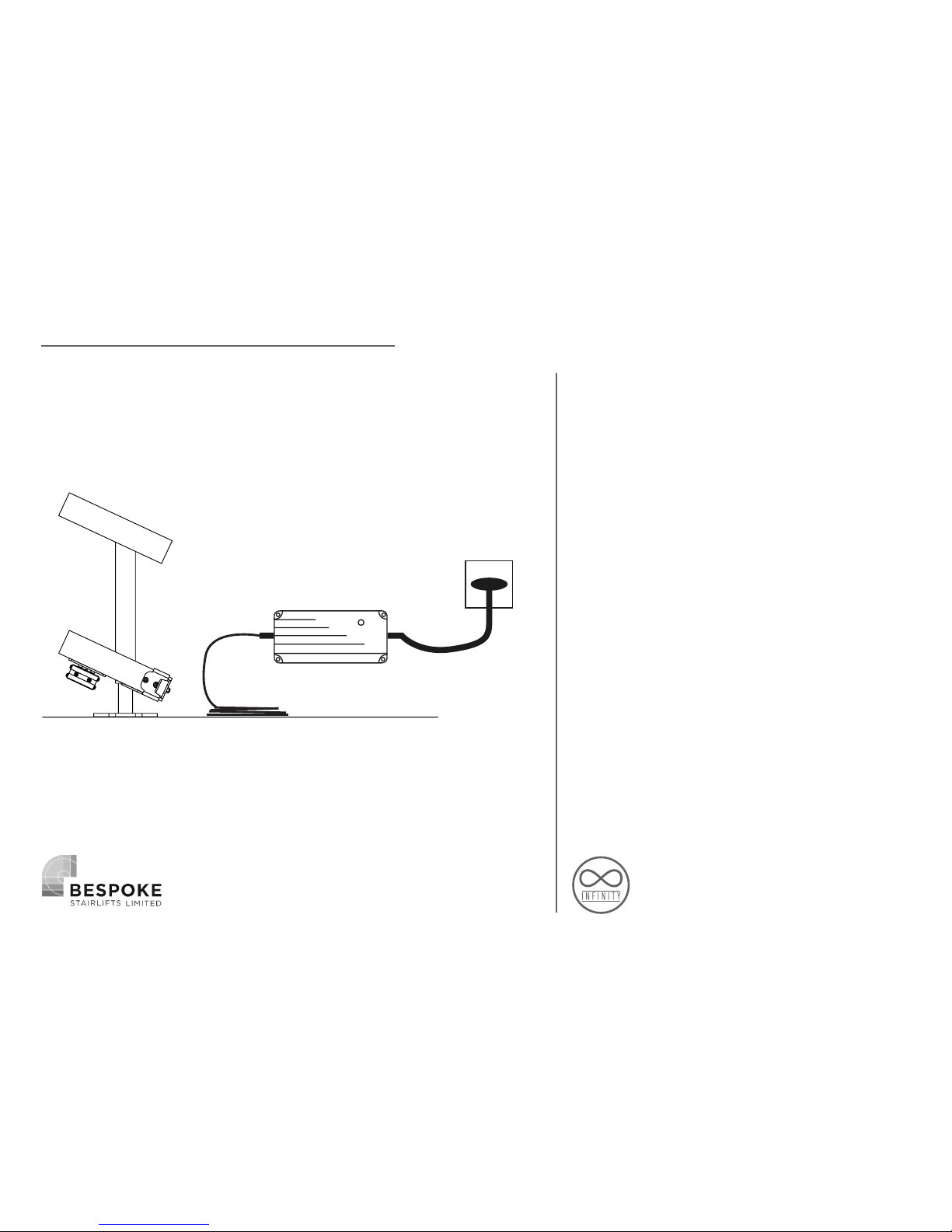
MOUNTING THE CHARGER
Find a suitable power supply as close as
possible to either the top or bottom of the
stairs.
Mount the charger in a suitable position
near the power supply using the screws
supplied. Please ensure the charger is
mounted level and secure.
Leave sufficient length on the power
output to enable easy connection to the
rail charge points.
Do not connect or switch on the power
supply until the rail charge points have
been connected. (See Page 31)
Power Supply
Charging Unit
Power Output
Cable
Page 10
10
CARRIAGE PREPARATION
Page 11
11
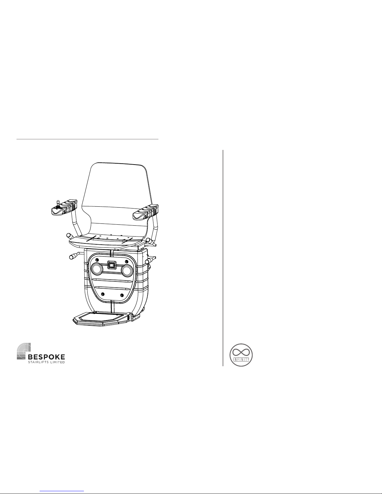
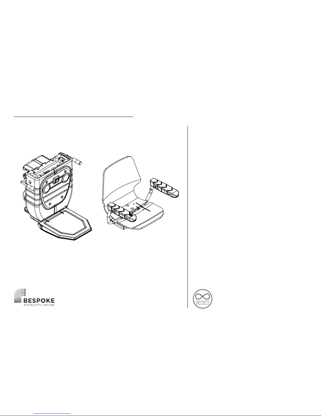
First unpack all the pre-assembled units
from their packaging, taking care not to
place the carriage on the floor, avoiding
damage. Your carriage will arrive already
pre-assembled as either a manual swivel
option or powered swivel option as per
your order.
CARRIAGE PREPARATION
CARRIAGE & FOOTREST SEAT & ARMREST ASSEMBLY
Page 12
12
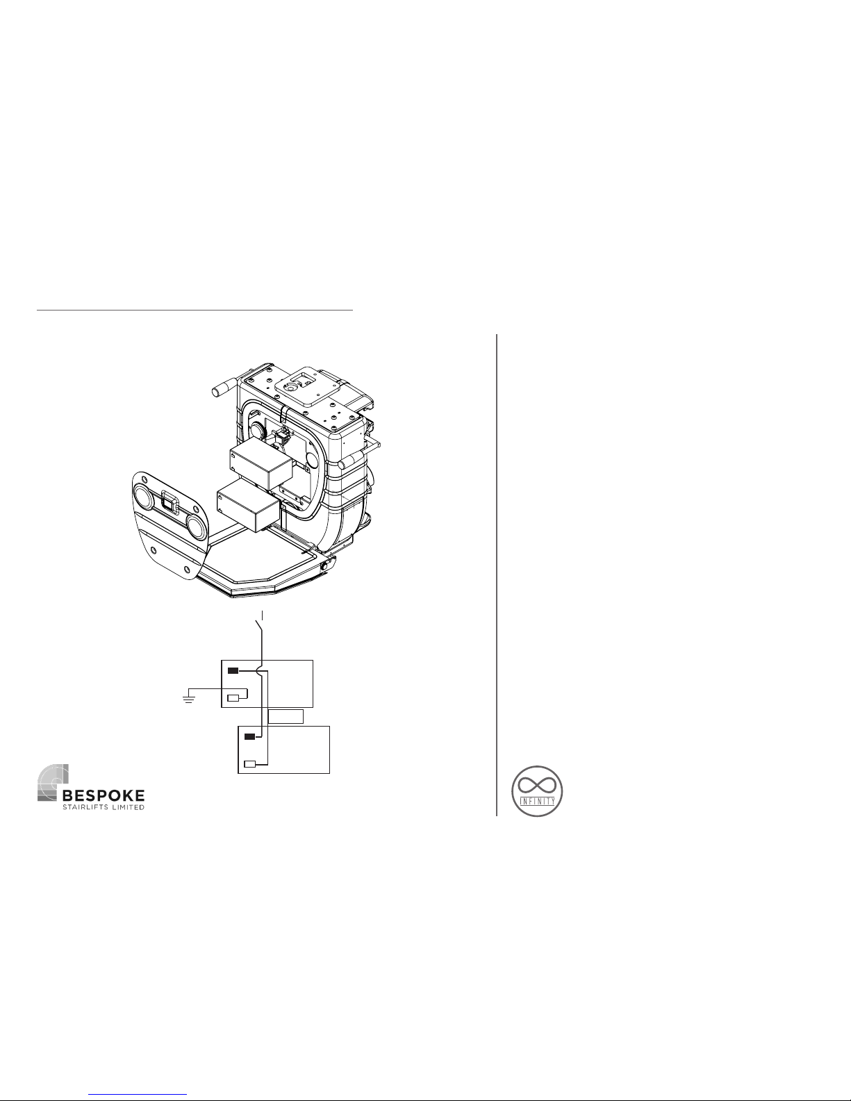
INSTALLING THE BATTERIES
To install the batteries first remove the
front panel by unscrewing the 4 main
screws. Once you’re have inserted the
batteries consult figure 2, making sure the
battery circuit is correct.
CARRIAGE ASSEMBLY
+
-
+
-
FUSE
Fig 1
Fig 2
Page 13
13
CARRIAGE PREPARATION
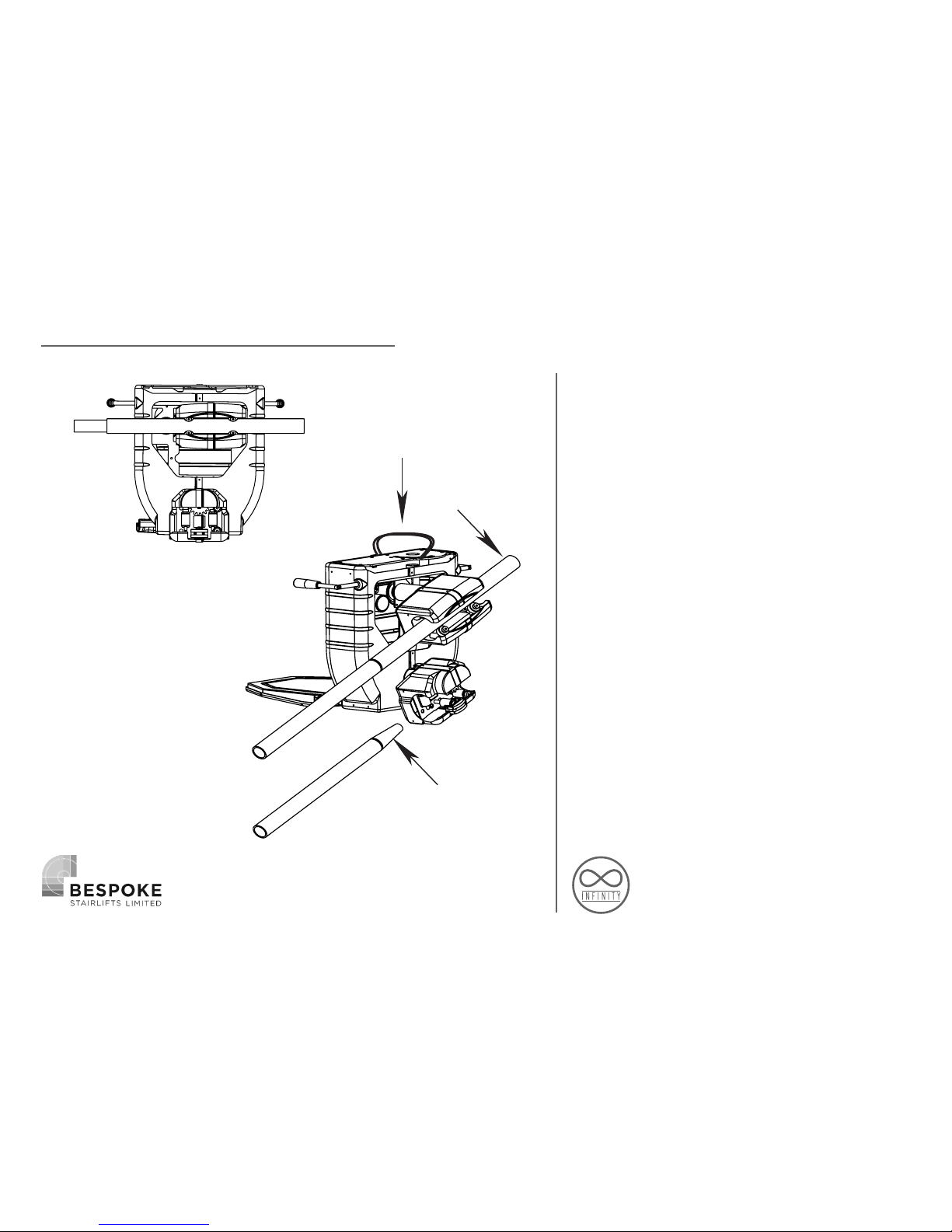
LOADING ONTO THE RAIL
Next insert the long loading bar into the
top skate of the carriage and insert the
small cone stopper in the bottom rail tube.
At the top of the stairs lift the carriage
with the loading strap and insert the
loading bar into the top rail tube, slowly
run the carriage along until the small cone
is through the bottom skate. Once the
carriage is securely located on rail it is
safe to let go of the loading strap.
(Loading bar & cone are part of the
separate installation kit.)
Small cone
Loading Bar
Loading strap
Fig 1
Fig 2
Page 14
14
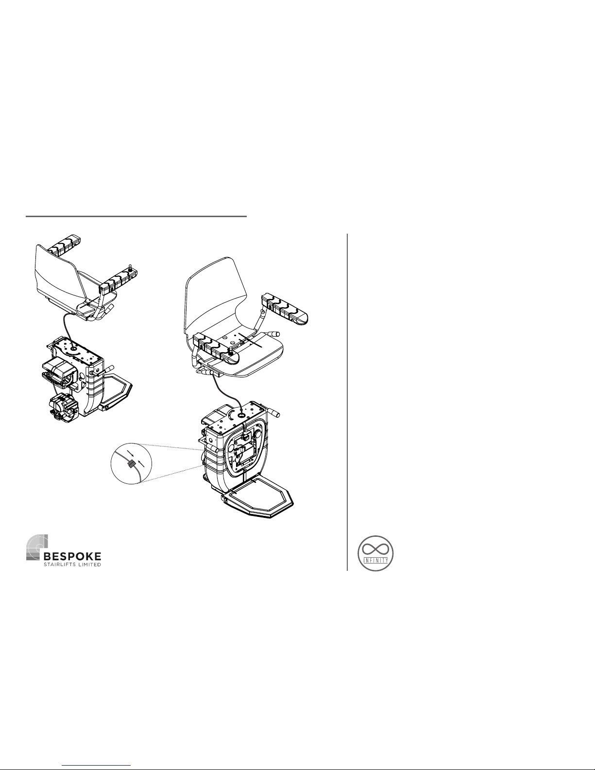
CONNECT THE SEAT BASE WITH ARMS
TO THE CARRIAGE
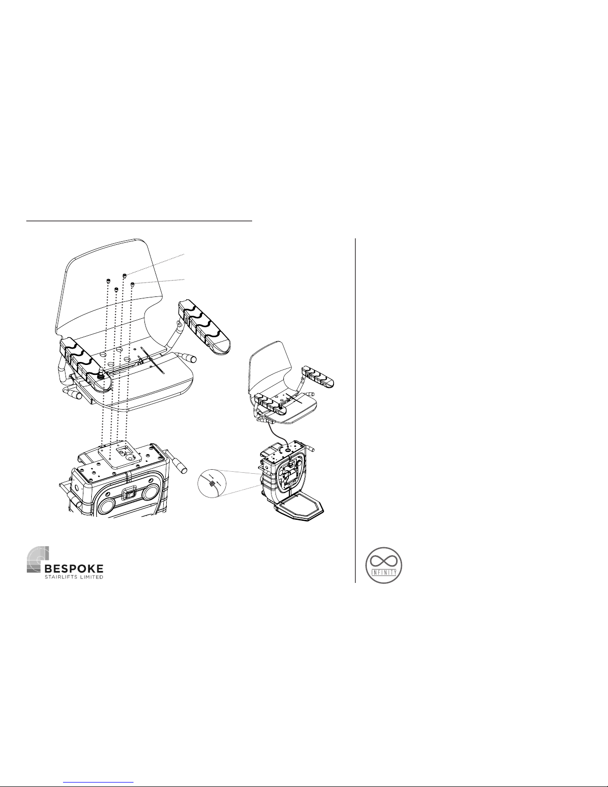
You can now begin to install the seat to
the carriage. First, lift the seat above
the carriage and feed the joystick cable
down through the hole located in the
seat boss plate, before lowering the seat
down onto the plate ensure to feed all the
cable through when doing so, to prevent
the cable getting trapped under the seat
frame. If the lift is a Manual Swivel, you
must ensure the locator on the swivel lever
is passing through the aperture in the boss
– this is not required on a powered swivel.
CARRIAGE ASSEMBLY
Page 15
15
Now line the holes up on the seat frame
down to the boss plate below. Fix with the
2 shorter bolts towards the front of the
seat, the 2 longer ones to the back. Please
ensure the correct screws are positioned in
the correct holes as incorrect installation
will result in damage. Then connect the
joystick cable to the PCB cable which is
located inside the chassis above the upper
battery (Fig 1), making sure the 2 cables
are free to move as the chair rotates, then
the front battery cover can now be fixed
back on. Insert the key into the arm and
turn to the in position, the carriage is now
ready to run down the rail.
CARRIAGE ASSEMBLY
Fig 1
2x Long Screws
2x Short Screws
Page 16
16
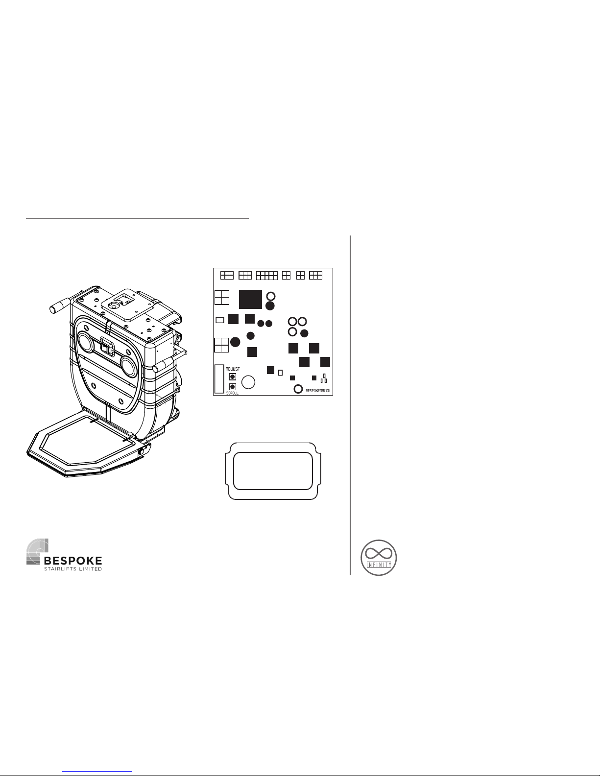
Switch on the lift by pressing the orange
switch on the front of the carriage to the
on position. Remove the PCB cover for
access to the programming buttons and to
have a clearer view of the LCD screen. The
lift should already come set up correctly
ready for programming, but this can be
checked by going through the menu
function on the screen.
The lower ‘SCROLL’ button is used to cycle
through the menu options and the top
‘ADJUST’ button to change an option. For
example, scroll to the Swivel option and
press the adjust button to choose Manual
or powered. It is best to check through all
these beforehand to make sure everything
is set up correctly.
RUNNING THE CHAIR ON
MANUAL
Page 17
17
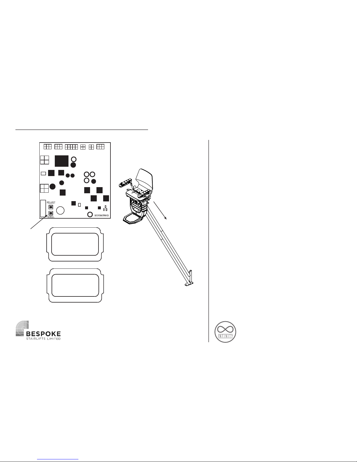
The lift will not run unless in program
mode or already programmed to the rail.
To put the lift into Program mode, Press
the scroll button until you see ‘POSITION’
(this is the first option you come to if
scrolling from the home screen), then
press and HOLD the scroll button and this
will change to ‘Program LO 1500’ – you are
now in program mode and able to drive
the lift onto the rail. Run the chair to a
desired position on the rail so you are now
able to start mounting the charging points.
RUNNING THE CHAIR ON
Position
PROGRAM
Lo 1500
HOLD
Page 18
18
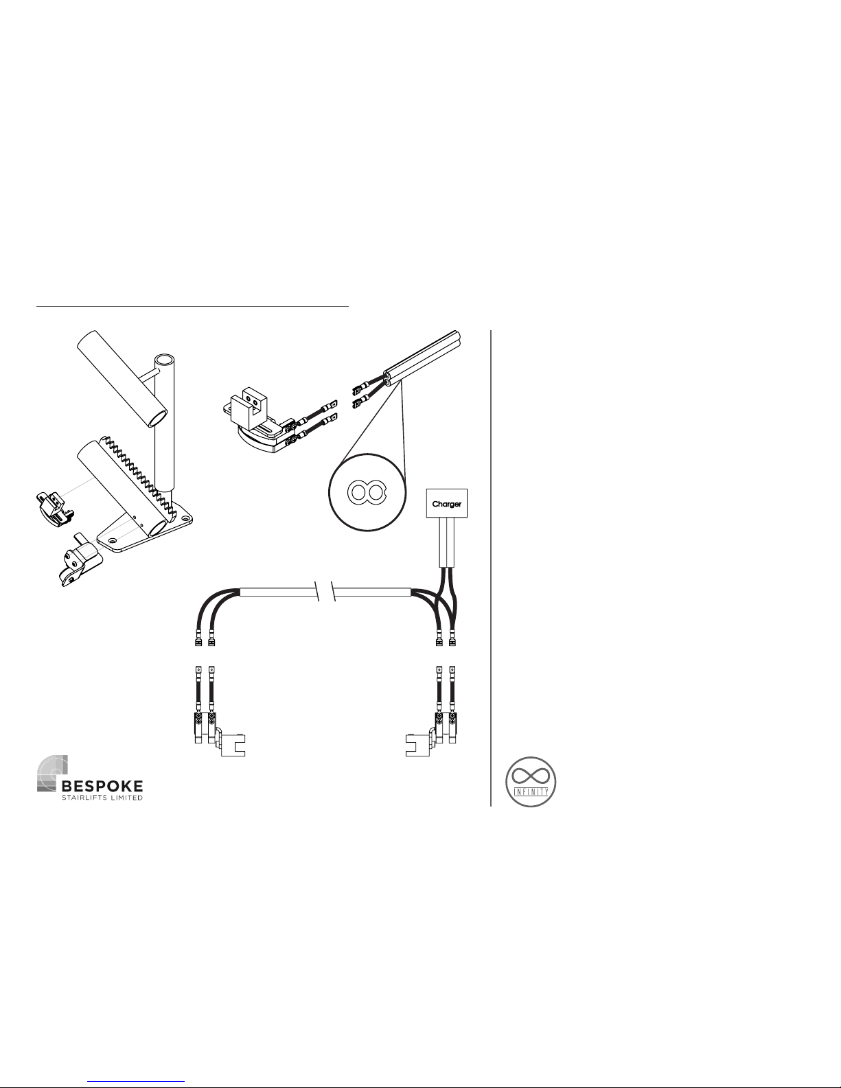
Return to the rail and fit the charge points
to both the top and bottom connecting
the core cable at both ends, use the
diagram in the installation guide to ensure
correct polarity (+ to the lower charging
strip and - to the top) once you are happy
with the positions fasten the final end stop
brackets at the top and bottom of the rail.
When placing the final end stops and
charging points please ensure;
1. The lower skate of the carriage does not
touch the floor before engaging with the
final end stop. This could result in damage
to the skate mechanism. If the distance
is incorrect you may need to adjust the
charging terminal.
2. When the charging terminals are
engaged make sure there is ONLY 5mm10mm gap between the end stop and
the skate cover, if for any reason the lift
overruns the charge points it will ensure
the lift is still on charge.
INSTALL RAIL CHARGE POINTS
+
+- -
+ -
+
-
Page 19
19
PROGRAMMING
HAND
This is to determine the hand of the lift
LEFT / RIGHT
MODE
Used for different lift types as will both Curved
and Straight lifts will use the same PCB &
software. *Straight lift not yet available*
CURVED/STRAIGHT
POSITION
Used for programming the lift to the rail (press
and hold scroll button to get in/out of Program
mode), also shows the encoder count once
programmed.
NO FUNCTION
Below is breakdown and explanation
of each of the menu options shown
on the display when using the scroll
/ adjust button. The home screen will
show lift status, for example, ‘LIFT
READY’ or OFF CHARGE’ before you
scroll through the menu, the display
will automatically go back to the
lift status after 5 seconds of neither
button being pressed.
Page 20
20
INT.CP
When the lift has an Intermediate Charging Point
(INT. CP) the lift will always park here from the remote
controls, but you have the option for the joystick,
PASS – to always pass the charge point when using the
joystick (when the lift only requires the charge point
STOP – To stop on the charge point when using the
joystick (usually required where the customer has an
intermediate landing they need to be able dismount
the lift).
PASS / STOP
TRAVEL
Option for the lift to BEEP when travelling up or
down the rail
QUIET / ALARM
LANGUAGE
Choose 1 of 7 language options;
English, Spanish,French,
German, Italian, Portuguese & Dutch
SELECT LANGUAGE
SWIVEL
This option is to set up whether the lift has a
manual or powered swivel
MANUAL / POWERED
PROGRAMMING
Page 21
21
SOFTWARE
VERSION
Used to determine the current software version of
the PCB.
NO FUNCTION
SPEED
This is used for factory assembly ONLY
NO FUNCTION
FAULT
LOGS
The PCB will record each fault / safety switch
ever activated on the unit. These can be reset
once repaired or serviced.
RESET FAULT COUNT
PRESS ON EACH FAULT
TRIPS
This logs how many the trips the lift has made
-this cannot be reset
NO FUNCTION
PROGRAMMING
*Once you have scrolled through all the menu
options, you will be taken back to option 1*
Page 22
22
PROGRAMMING
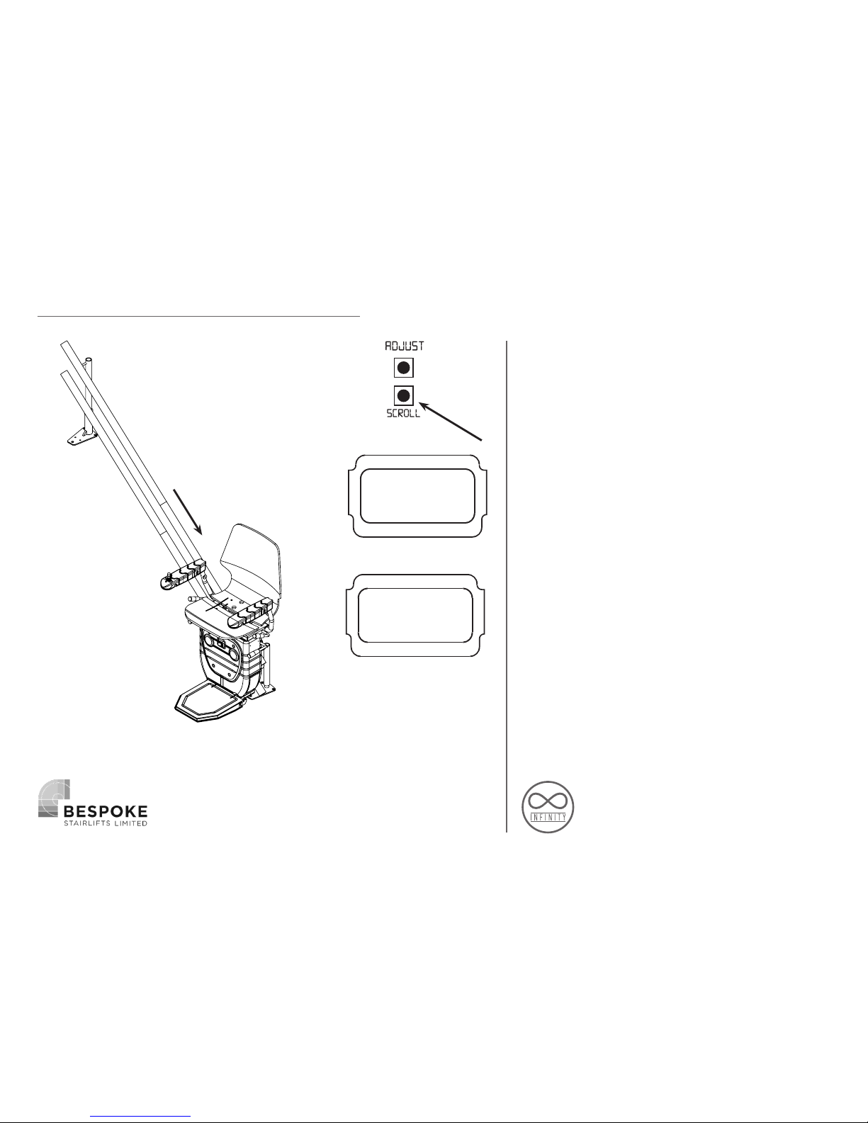
Next, to program the Stairlift, put the
lift into Program mode and begin to
run it down the bottom charge point,
making sure the charger is turned on
before making contact, If you have an
intermediate charge point, turn the
charger on when you are below this so
that the bottom charge point is the first in
which the lift detects. Once the lift reaches
the charge point it will stop automatically
and the counter will reset to a number
around 1000, this is the datum point in
which the lift will count from.
1000
2
1
3
Position
Page 23
23
PROGRAMMING
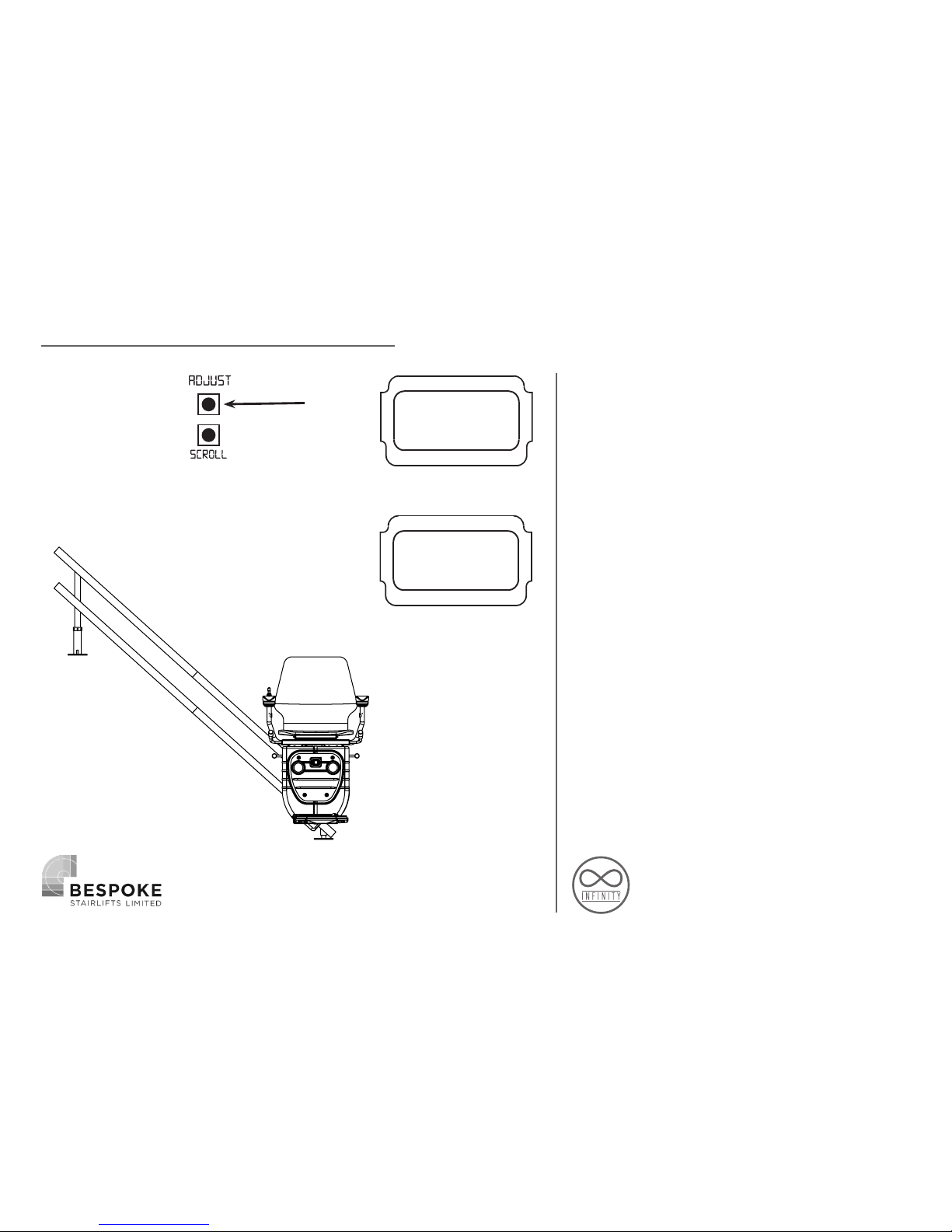
The ‘LO’ shown on the screen is the speed
the lift will travel after programming,
press the adjust button to change to ‘HI’
to program the lift to full speed, the speed
can be changed at any point on the lift as
you travel up to the top charge point by
pressing the adjust button again to select
between ‘HI’ & ‘LO’, this will only need to
be adjusted on internal curves.
Lo
HI
2
3
1
Page 24
24
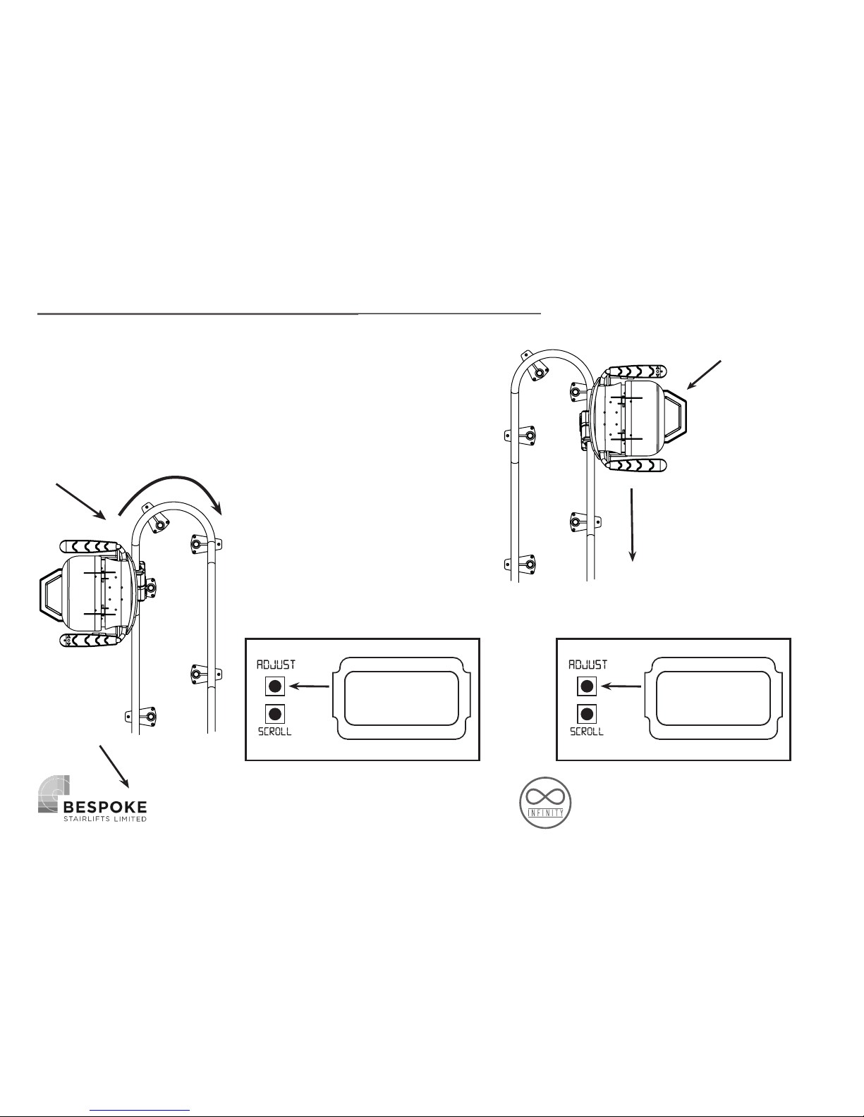
PROGRAMMING THE BEND SLOWING FUNCTION (Optional)
Note: To program using the slowing function The Infinity
Stairlift must be programmed using following the steps;
1. Once Programmed as described on pages 19-21
2. Move off the first charge point
3. Follow the steps below.
4. Move to final terminal.
To slow The Innity
Stairlift when travelling
around the bends the unit
must be programmed the
following way;
Position the Stairlift where
you would like to start the
slowing function
Push ‘Adjust’ until the
display reads ‘LO’
2.Press ‘Adjust’
to move to ‘LO’
3.Move around
the bend
Move the Innity Stairlift
Around the bend to
the position where you
would like the slowing
function to stop then;
Push ‘Adjust’ until the
display reads ‘HI’
1. Start on
the bottom
chargepoint
5. Move to final
Terminal and
4.Press ‘Adjust’
to move to ‘HI’
Lo HI
Page 25
25
PROGRAMMING
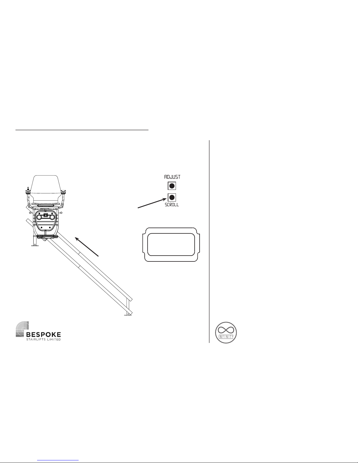
Now begin to drive the lift up to the next
charge point, where the lift will again stop
by itself when it detects the charge point,
if this is an intermediate drive the lift up
again until you reach the top. Once the lift
has stopped on the last charging point,
press and hold the scroll button again until
‘POSITION’ is shown on the screen again –
The lift is now programmed to the rail.
Position
2
1
HOLD
Page 26
26
REMOTE CONTROL
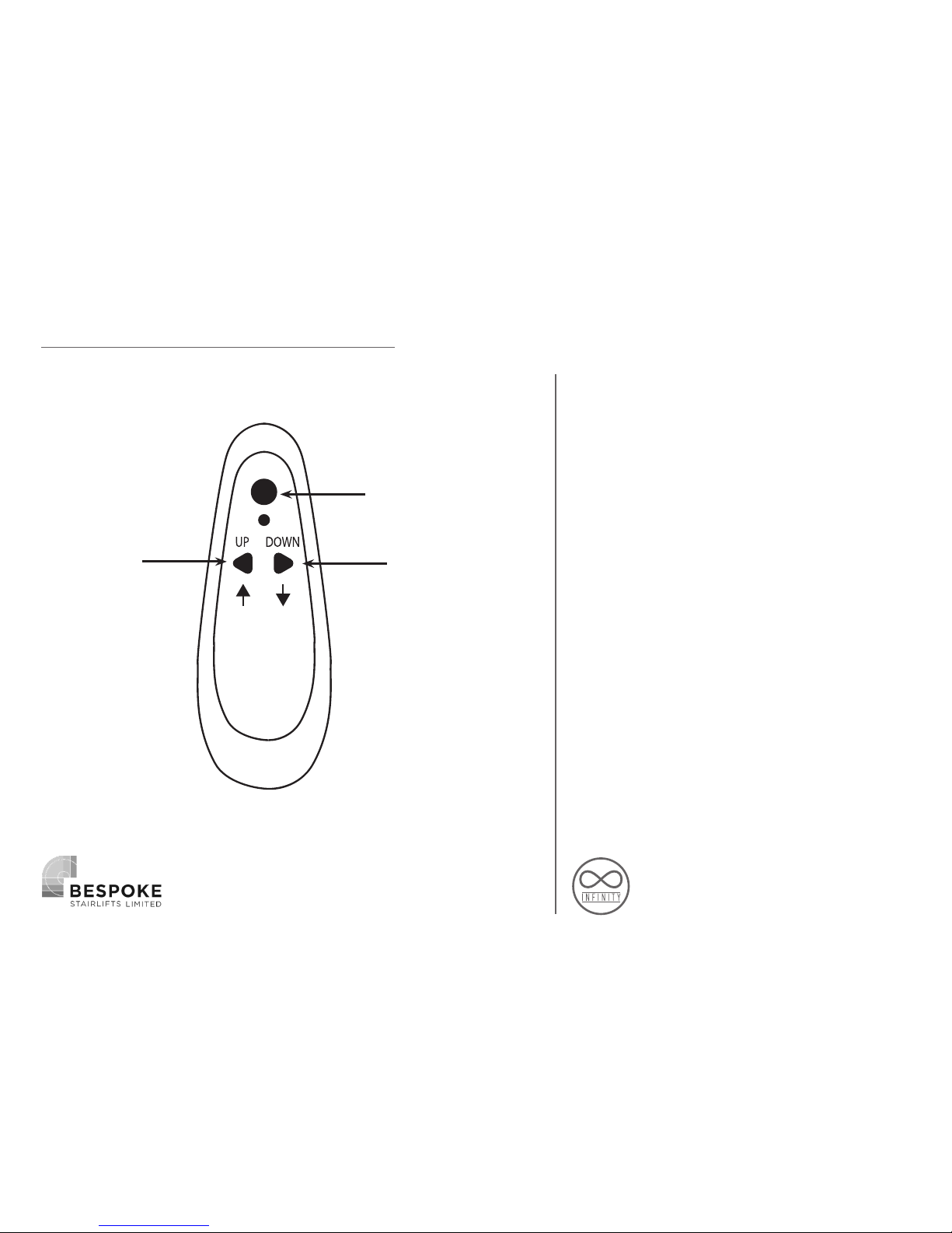
The remotes will already come preprogrammed to the lift, should you need
to program them, turn the lift off/on again,
then within the first 5 minutes of the lift
being switched back on, press and hold
all 3 buttons on the remote control for 3
seconds, repeat the process again for any
additional remote controls, The remotes
will now be paired to this lift.
HOLD
HOLD
HOLD
Page 27
27
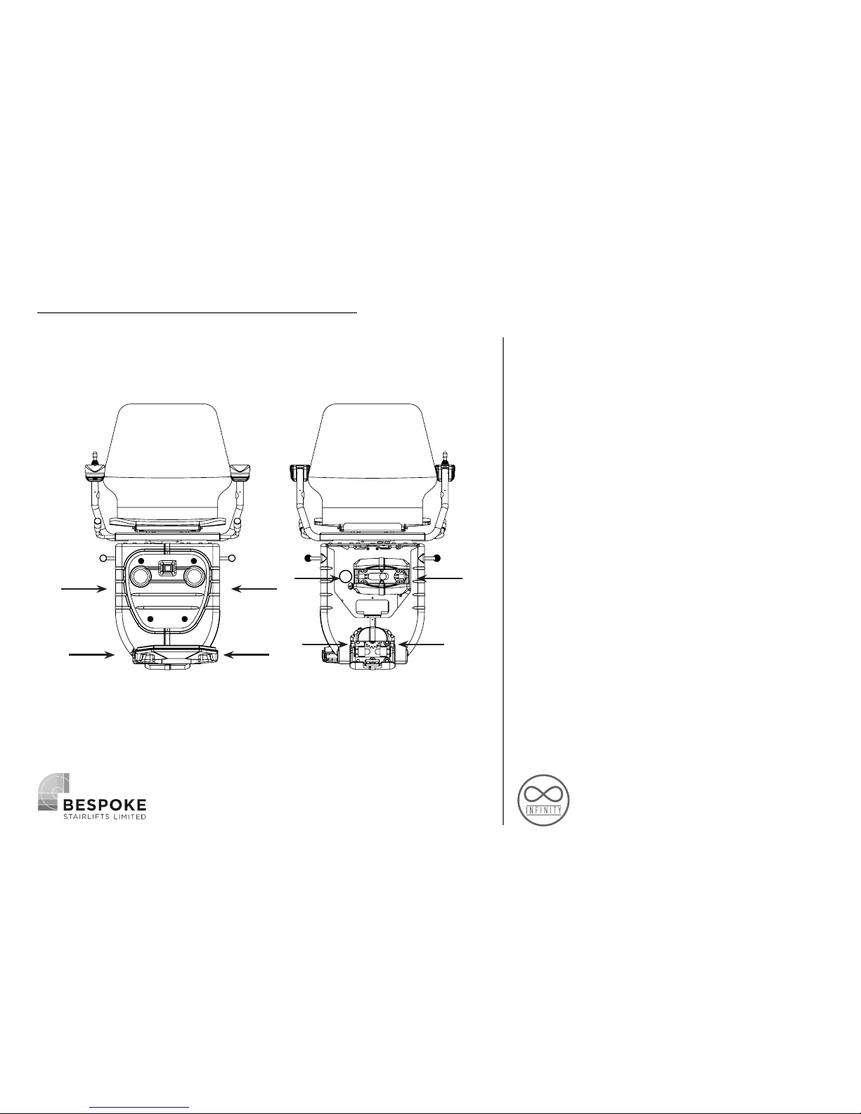
TROUBLESHOOTING & SAFETY
Here we are going to quickly check the
stopping safety features. First move the
Stairlift to a convenient position, now run
the Stairlift placing you hand in front of
each sensor individually running the lift
both up and down the rails.
Front Back
Page 28
28
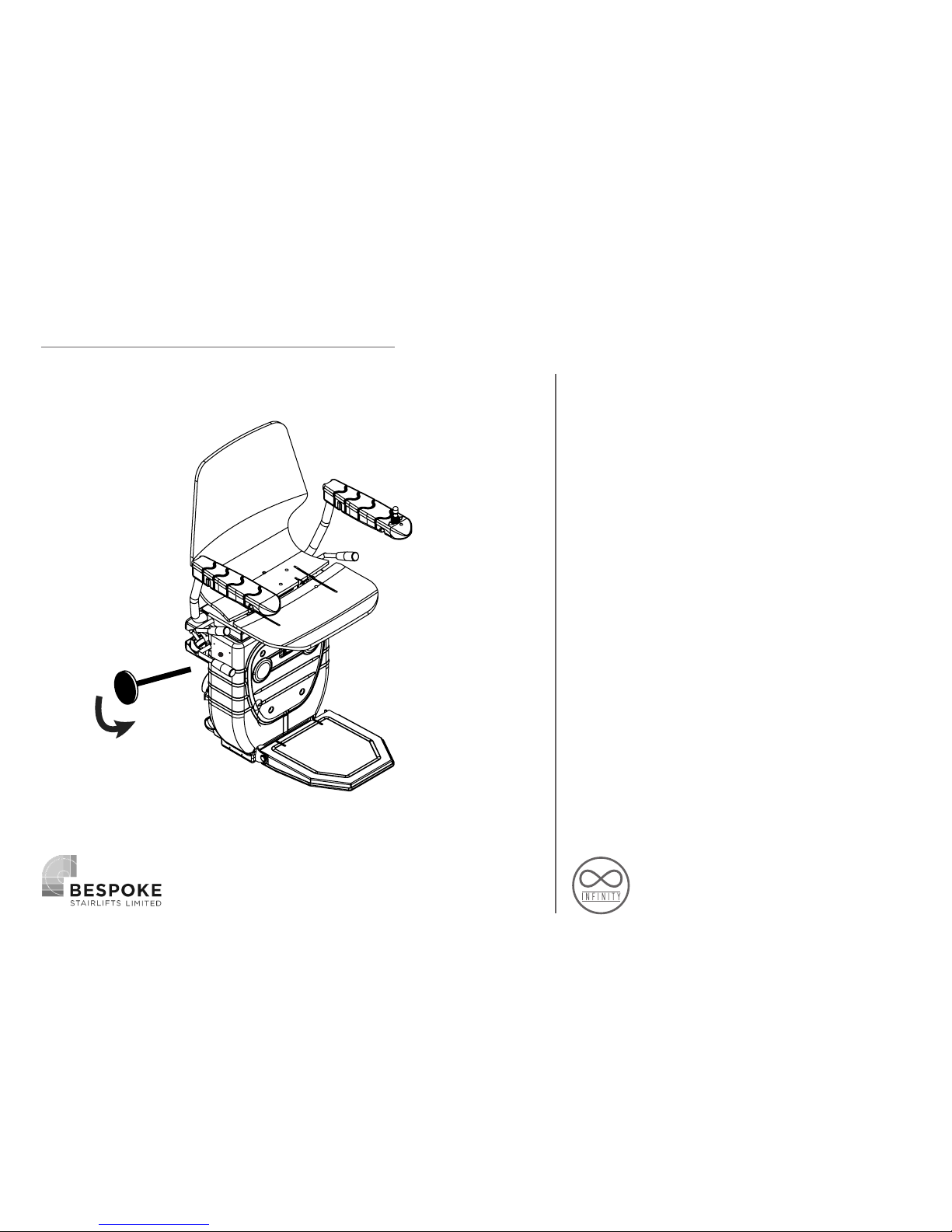
Manually insert the winding handle
into the hole located on the left side
of the carriage and locate the winding
mechanism. Engage the winding
mechanism and manually turn the handle.
To release the over-speed governor (OSG)
wind the stairlift in the upwards direction
to release the OSG arm.
MANUAL OVERRIDE
Page 29
29
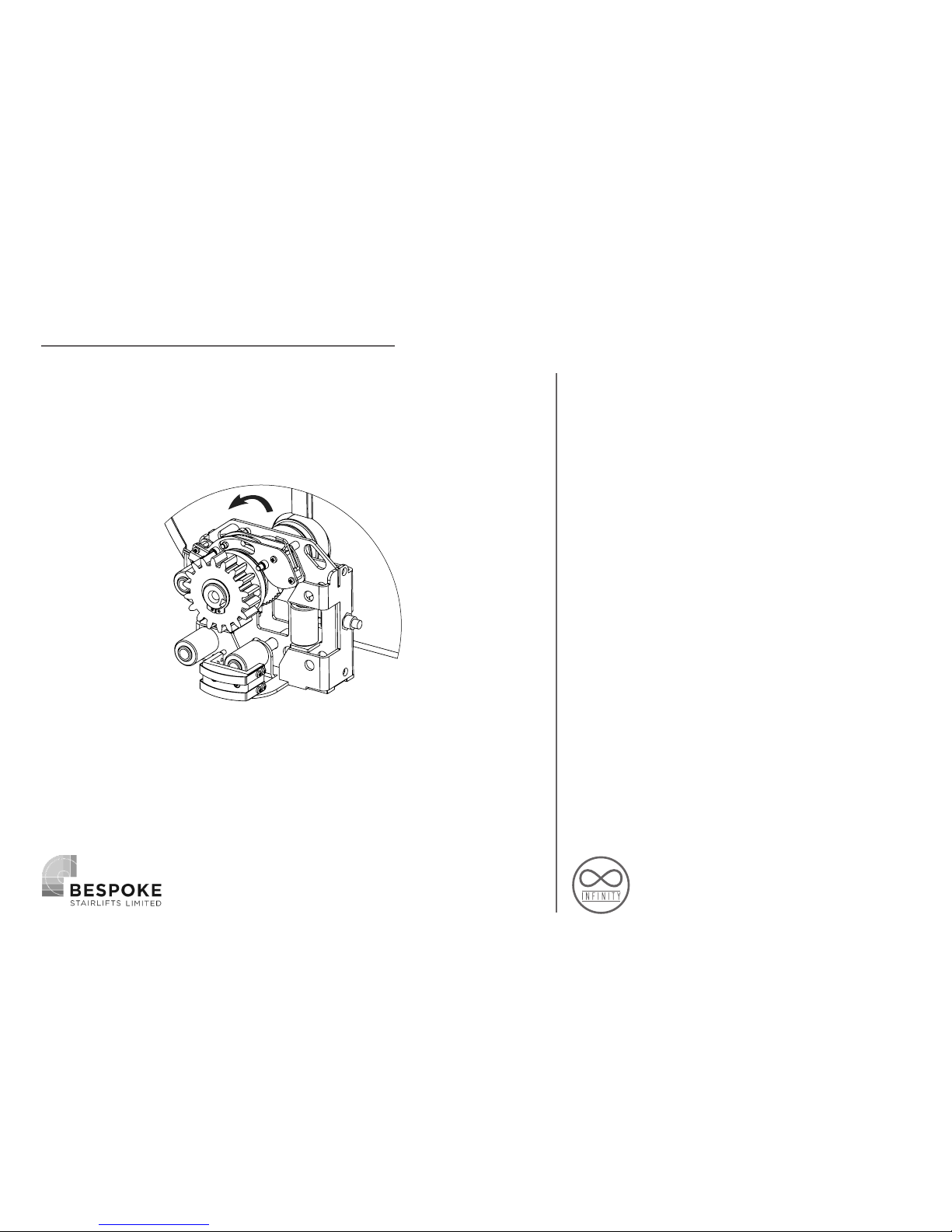
Run the lift upwards with the manual
override, the OSG should come loose from
the tube then.
Make sure that the OSG is in neutral
position again.
The unit does not need re-programming
RESET THE OSG
Page 30
30
THE DISPLAY DIAGNOSTICS
The Display diagnostics feature
that can inform the engineer of
any problems that The Infinity
Stairlift has encountered during
installation or in general use.
Depending on the problem The
Infinity Stairlift diplays a selection
of error messages to indicate
what the problem is enabling the
engineer to pinpoint the fault and
resolve quickly without the need
of elimination of other potential
faults
OFF
CHARGE
Lift not charging
•Check lift is parked on a
charge point
•Check the voltage at the
charge point, the power is
turned on and polarity is
correct.
FOOTREST
LEFT/RIGHT
Footrest safety
switch activated
•Check for obstructions and
covers able to move freely
•Check Footrest wiring loom
for continuity as marked on
the PCB and using the wiring
diagram for correct switch
cables
Page 31
31
THE DISPLAY DIAGNOSTICS
SEAT
Left/right
Main chassis safety
switch activated
•Check for obstructions and
covers able to move freely
•Check Mainframe wiring loom
for continuity as marked on
the PCB and using the wiring
diagram for correct switch
cables
BOTT.SKA
LEFT/RIGHT
Bottom skate safety
switch activated
•Check for obstructions and
covers able to move freely
•Check Bottom Guidance
wiring loom for continuity as
marked on the PCB and using
the wiring diagram for correct
switch cables
top.SKA
LEFT/RIGHT
Top skate safety
switch activated
•Check for obstructions and
covers able to move freely
•Check Top Guidance wiring
loom for continuity as marked
on the PCB and using the
wiring diagram for correct
switch cables
Page 32
32
SEAT
SWIVEL
Seat swivel safety switch
activated (will also show when
powered swivel is in motion)
•Check seat is in home
position
•Check swivel switch is open,
located on the swivel boss
cam above the batteries.
•Check continuity on
orange wire located in the
mainframe loom.
R.M.U.
Fault
R.M.U reed switch is not
receiving a signal
•Check white OSG roller
is rotating when the lift is
travelling. The 2 magnets must
pass the sensor to give a pulse
in less than 7 seconds
•Check grey wires on bottom
guidance loom for continuity
Over
Speed
Over speed switch is activated
•Check O.S.G assembly is in
neutral position, if not reset
and try run the lift again
•Check Orange wires on
bottom guidance loom for
continuity
THE DISPLAY DIAGNOSTICS
Page 33
33
Over
Current
Lift is drawing too
much current
•Check rack / pinion is clear for
the lift to move
•Check the lift has not hit the
overrun plate on the End stops
•Check customer weight does
not exceed limit
Relay
Fault
Relay is sticking on main PCB
•Gently tap the relay to free
the mechanism, if this doesn’t
work, a new PCB will be
required
FAULTS NOT SHOWN
ON DISPLAY
Board has no power, but
LED 1 is activated
•There is a live short on a safety
line, un plug each connector on
the PCB until the light goes out,
this will determine which loom the
short is on and you are able to test
for continuity to the chassis to nd
the short. The PCB is designed to
handle a short instead of requiring a
fuse.
Lift will only work
from Remote controls
•Check both arms are horizontal
(arm interlock switch is present in
downside arm)
•Check key switch is turned on /
wiring (wiring for interlock is in
series with the key switch)
THE DISPLAY DIAGNOSTICS
Page 34
34
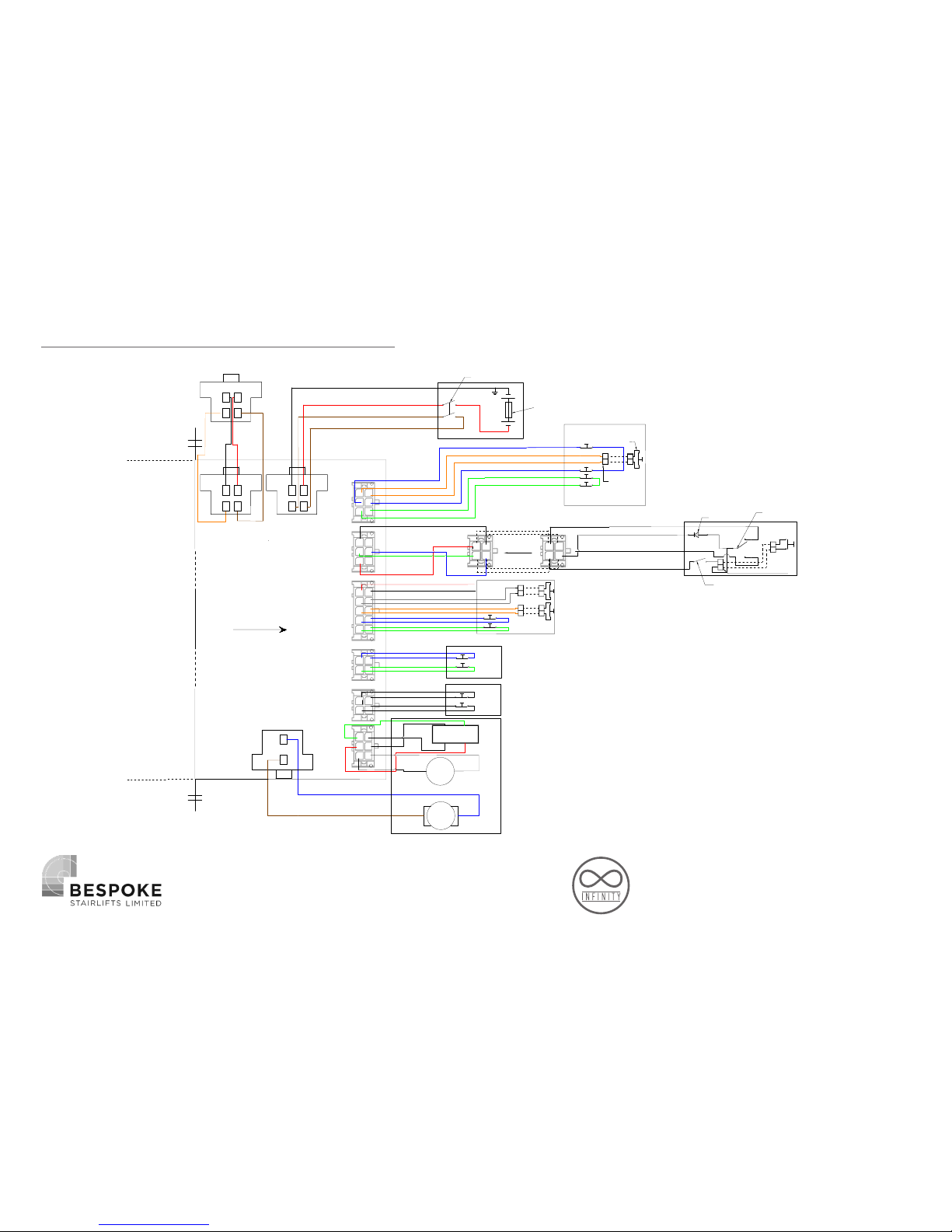
INFINITY WIRING DIAGRAM
Swivelsensor
Safety Right
Safety Left
LED Ground
Joystick left
Main Positive
Joystick right
Rotationsensor
Chargingpoint negative
Chargingpoint
Groundbattery
Tractionmotor 2
Footrest
Up.Guidance
Bot.Guidance
Chair
Mainframe_2
Safety Left
Safety Right
Safety Left
Safety Right
M
Encoder
Motor
Move 1
Move 2
Chargingpoint positive
Safety OSG
Safety Right
Safety Left
Battery Positive
Black
Red
Brown
Brown
Blue
Orange
Orange
Blue
Green
Green
Black nr.2
Black nr.3
Black nr.4
Black nr.1
Red
Black
Grey
Grey
Orange
Orange
Blue
Blue
Green
Green
Blue
Blue
Green
Green
Black nr.2
Black nr.4
Black nr.3
Black nr.1
Black
Blue
Brown
2 1
2 1
armrest
sensor
connect to armrest sensor
B
1
2
3
4
5
6
6
3
2
5 4
1
6
3
2
5 4
1
6
3
2
5
4
1
7
8
9
10
1
2
3
4
3
1
4
2
1
2
2
1
2
1
2
1
1
2
4
3
Mainframe
Brake
Black
Blue
Green
Red
4
2
1
3
connect
Black
Black
White
Red
Green
Black
Red
Brown
Orange
Tractionmotor
Extension
module
1
2
3
4
3
4
2
1
3
4
2
1
1
2
2 1
2 1
Swivelsensor
Connect to
swivelsensor
Mainswitch
30A Fuse
Mainframe
Chair
Joystick
Keyswitch
Bottom skate
Upper skate
Foot rest
Motor
(Optional)
1
2
1
2
2
3
1
LED
Topside
l
of PCB
Page 35
35
Bespoke Stairlifts
Of
Unit 9, Old Fieldhouse Industrial Estate,
Old Fieldhouse Lane, Hudderseld,
West Yorkshire, HD2 1FA, England.
Declare under our sole responsibility that the products
INFINITY STAIRLIFT
have been manufactured in conformity with the
following standards and specications:
EN 81-40:2008
And the products to which this declaration relates
are in conformity with the following EU directives:
Electro Magnetic Compatibility Directive 2004/108/EC
Low Voltage Directive – 2006/95/EC
Machinery Directive – 2006/42/EC
Signed:........................................................................
On Behalf of Bespoke Stairlifts Limited
Date:............................................................................
CERTIFICATE OF CONFORMITY
Technical Documentation is available upon request
from Bespoke Stairlifts at the address above.
1st December 2016
Page 36

36
• DEMONSTRATION
• EXPLANATION
• USER SAFETY
• USER BOOKLET
• PAPERWORK COMPLETION
1) Ask user to stand clear of the stairlift making sure that they have a
clear view of the lift.
2) Demonstrate the operation of the seat and footrest (manual or
powered if tted); advise the user to stand clear of the footrest to
avoid the footrest coming into Contact with the users legs.
3) Explain the L.E.D. functions on the chair arm clearly.
4) Explain the operations and positions of all the on/o switches.
Explain that the Key switch should always be turned o before getting
in/out of the chair.
5) Explain the operation and position of the directional controls on the
chair.
6) Explain that if constant pressure is released from directional
controls the lift will stop, and there is approximately a three second
delay before the stairlift will restart.
7) Explain the swivel function (manual or
powered, if tted) and also that the lift will stop automatically at the
top and bottom of the rail. Explain manual override of a powered
swivel if tted. Demonstrate and explain the manual override function
should only be used if a fault develops with the power functions, and
when used, should only swivel in the up direction as a safety measure.
On N0 occasion should the manual override function allow the user to
swivel the chair in
the down direction.
8) Ask the user to sit comfortably on the
seat and explain the use of the seatbelt (the seatbelt should always
by used). Ensure the user does not extend their arm beyond the seat
back.
9) Ask the user to operate the stairlift to the top of the stairs. Go up
rst so as not to block your own access.
10) Ensure that a swivel operation is carried out, and the customer
alights from the lift.
Ensure the user has turned o the chair Key switch.
11) Ask the user to complete a downward journey.
12) If the stairlift has a hinge, then this
option will have to be fully explained at this point, all controls,
interlocks, safety features, and general operation.
13) Once the user is clear on the operation of the lift show the
operation and position of all safety edges.
14) Ensure that all of your instructions have been clearly understood.
15) Invite the user to sit down comfortably while you explain the user
handbook. Ensure that the Service details are pointed out.
16) Ask the user to read and sign the handover sheet and any other
supporting documentation. Explain that the handover sheet is also a
receipt for any payment collected.
DEMONSTRATION AND HANDOVER
Page 37

37
INSTALLATION TOOLS
1) 2 ft (500mm) spirit level (approx) 2) Extension Bar 3/B” or W drive)
3) Tape Measure ~ 5 metres
4) 6mm twist drill bit (15/16”)
5) 8mm masonry drill bits
6) Hexagon keys one set- Sizes: 2 -
10mm (‘T handles or long series) 7) Combination spanners, one set-
Sizes: M8 to M24
8) Crimping tool
9) Cross-head screw/drivers, one set
(variable sizes)
10) Dust sheet
11) Electric drill (Variable speed/
Hammer action / Chuck size 13m minimum)
12) Electrical or combination pliers 13) Electrical side cutters
14) Extension lead (heavy duty) 15) External circlip pliers
16) Flat blade screwdrivers, one set (variable sizes)
17) Hammer 20oz (claw or ball pen) 18) Long nose pliers
19) Magnetic angle nder
20) Digital Multi meter/Clamp meter
(must be capable of measuring DC
current at 30A for at least 5 seconds) 21) Nut runners - sizes: 5mm,
5.5mm, 7mm, 8mm.
22) Stanley knife (utility knife)
23) Lube grease
24) Terminal screwdriver
25) Torque wrench drive range 12 - 68Nm (3/8” or W drive)
26) Vacuum cleaner
27) Wire stripper
28) Wiring mouse - approximately 6m 29) Bit/socket set- 2.5 - 10mm
(3/S” or W drive)
30) Anti Static Wrist Strap
31) 3/8” or W square drive sockets range 8 -19mm
32) 24mm socket
33) Ratchet 3/8” or W drive
34) ®30mm Hole Saw/Cone Cutter
TOOLS AND EQUIPMENT
Page 38
38
Infinity Stairlift
Rail
Carriage
Seat
Huddersfield • England
 Loading...