

Besantek BST-PM77 Instruction Manual
POWER METER
INSTRUCTION MANUAL
Test Equipment Depot - 800.517.8431
99 Washington Street Melrose, MA 02176
TestEquipmentDepot.com

INDEX
1. INTRODUCTION................................
2. SAFETY NOTES................................
3. FEATURES........................................
4. SPECIFICATIONS..............................
5. INSTRUMENT LAYOUT.....................
6. MEASURING METHODS...................
6-1. Main buttons functions for power
meter...........................................
6-2. Screen mode...............................
7. CLEANING & STORAGE...................
8. PC COMMUNICATION METHOD......
9. INTERFACE CONNECTION AND
OPERATION.......................................
10. RS232 PROGRAM...........................
10-1. Initial screen and setting............
10-2.
Data collection and data analysis.
10-3. Data analysis ............................
10-4. Print setting....................... .. .. .. .. .
PAGE
1
2-3
3
4
5
6
6-7
8-16
16
17
18-20
21
21
21-26
27-30
31-32

-1-
1. INTRODUCTION
NOTE
This Power Meter has been designed and tested
according to CE Safety Requirements for Electronic
Measuring Apparatus, IEC/EN 61010-1 and other safety
standards. Follow all warnings to ensure safe operation.
WARNING
READ "SAFETY NOTES" (NEXT PAGE) BEFORE
USING THE METER.
CAT
Ⅳ
– Measurements performed at the source of the
low voltage installation.
CAT
Ⅲ
– Measurements performed in the building
installation.
CAT
Ⅱ
– Measurements performed on circuits directly
connected to the low voltage installation.
CAT Ⅰ– Measurements performed on circuits not directly
connected to mains.

-2-
2. SAFETY NOTES
1. Read the following safety information carefully before
attempting to operate or service the meter.
2. Use the meter only as specied in this manual.
Otherwise the protection provided by the meter may
be impaired.
3. The operating voltage is limited to ±10% of line voltage
100-240 Vac. Do not use it in other voltage rating.
4. Keep drying when using this product.
5. To reduce the risk of electric shock, do not remove
cover.
6. Do not use this product while is getting wet.
7. Never give shocks, such as vibration or drop, which
may damage the meter.
8. The maximum output current is 15A.
9. Rated environmental conditions :
(1) Indoor 100V~240V Vac.
(2) Installation Category II.
(3) Pollution Degree 2.
(4) Altitude up to 2000 meter.
(5) Relative humidity 80% max.
(6) Ambient temperature 0~40℃.

-4-
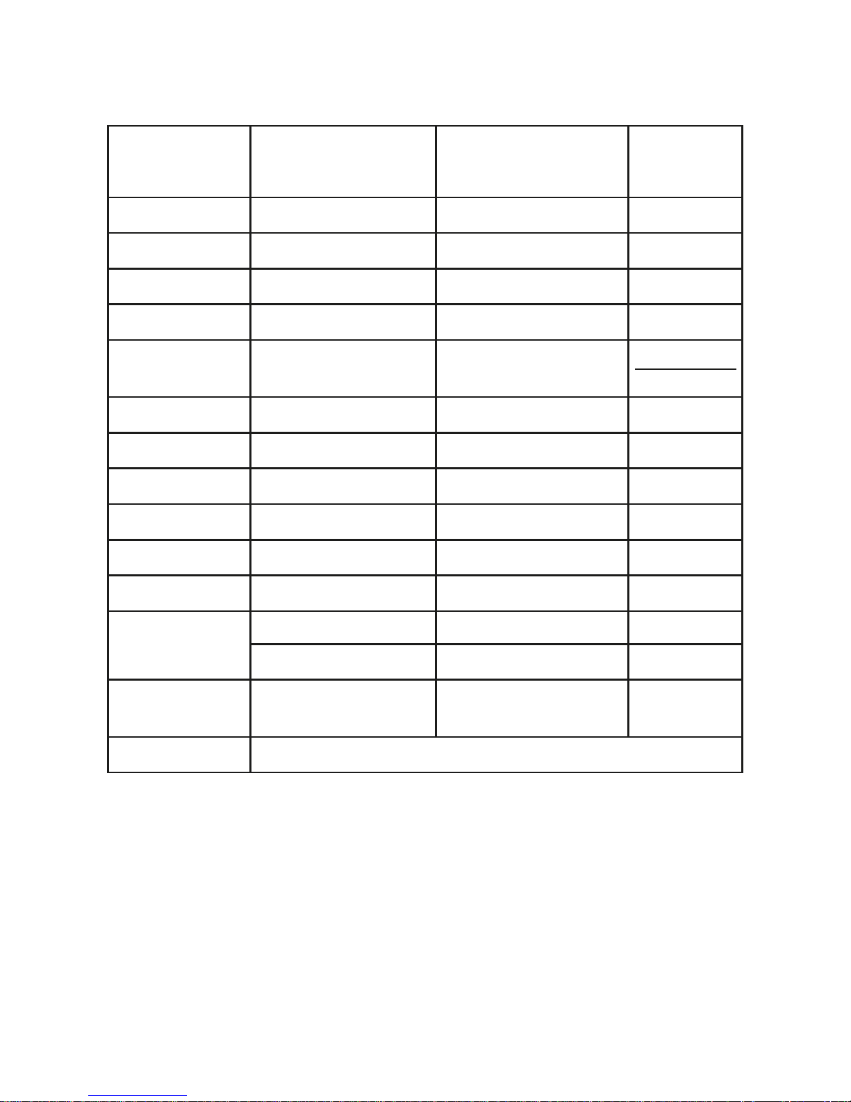
4. SPECIFICATIONS
Item Range Unit Accuracy
AC voltage 100-240 V rms ±1%
AC current 15 A rms ±1%
Power 0-3750 W ±1%
Apparent power 0-3750 VA ±1%
Power factor 0.001-1
Watt
V
rms * A rms
Frequency 45-65 Hz ±1%
Cost 9999 $
Energy 9999 kWh
Gas 9999 kg
Cost setting 0-9999 kWh
Gas setting 0-9.999 kg/kWh
Time duration
23 Hours
30 Days
Run-time
measurement
30:23
Days:Hours
Fuse rating 15A/250V (5×20 mm)
● Dimensions : 221(L) × 110(W) × 56.8(D)mm
● Weight : Approx. 760g
● Cable length : 150cm
● Safety standards : EN 61010-1
EN 61326-1
-5-
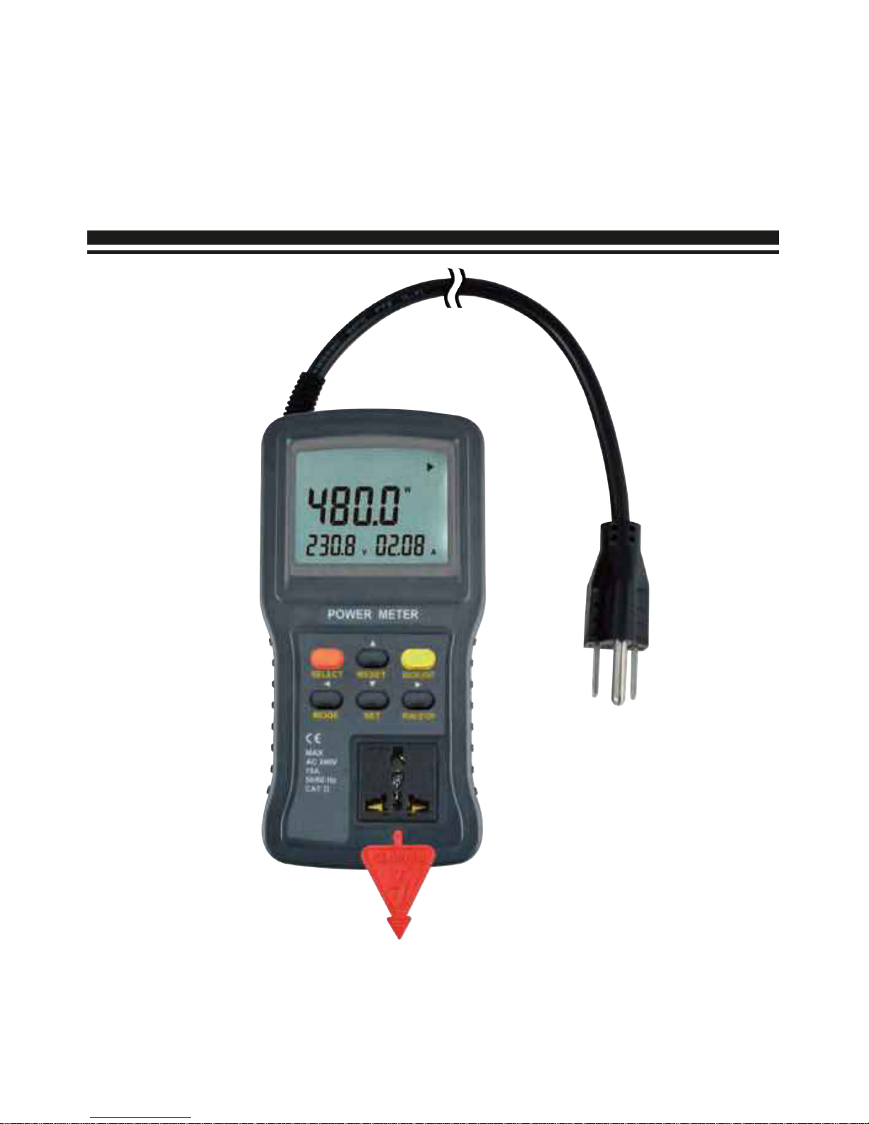
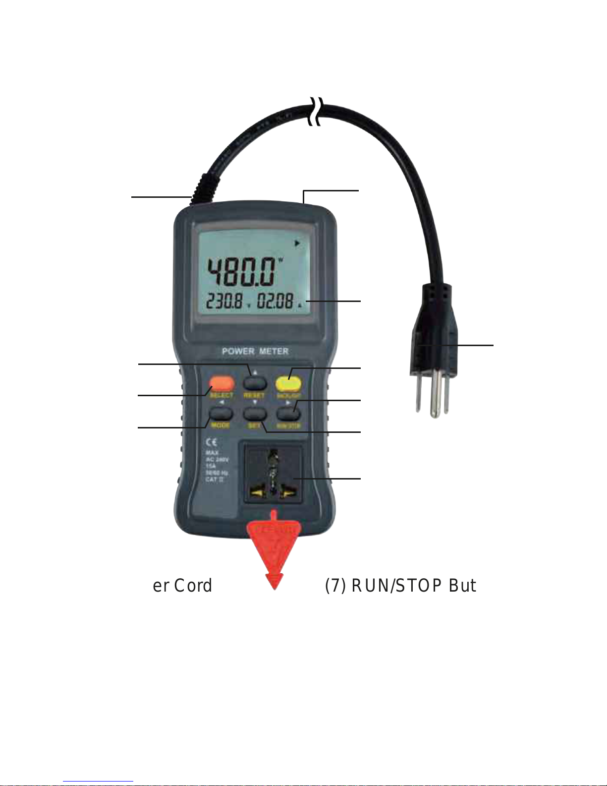
5. INSTRUMENT LAYOUT
(1) Power Cord (7) RUN/STOP Button
(2) RESET Button (8) BACKLIGHT Button
(3) SELECT Button (9) Display Screen
(4) MODE Button (10) Plug
(5) Universal Receptacle (11) The connection
(6) SET Button terminal for PC
interface
(1)
(4)
(3)
(2)
(5)
(7)
(6)
(8)
(9)
(10)
(11)

-6-
6. MEASURING METHODS
The meter is a multiple measurement function of AC
power meter.
Those functions are voltage, current, watt, va, frequency,
power factor, power consumption and actual cost of
power consumed measurement.
Installation:
1. Turn off the appliance and remove the power cord
from the outlet. Connect the meter to the outlet and
appliance to the meter.
2. LCD display will show measuring value.
6-1. Main buttons functions of power meter
MODE Button :
You can select different modes by pressing MODE
button.
These modes are watts, power factor, apparent power,
frequency, AC voltage, AC current, kWh, GAS, cost and
time mode.
SELECT Button :
When the main modes are watts, apparent power, AC
voltage, AC current modes, press the SELECT button
can see the detail of maximum and minimum on the
display.
Other main mode like kWh, GAS, COST mode when
pressing the SELECT button, you can see the detail of
REAL, HOUR, MTH duration on the display.
Under the time mode, press the SELECT button can
select different display of time mode, (min/sec) mode,
(hours)mode, (days/hours)mode.

-7-
SET Button :
1. Alarm function:
Under the watt, AC voltage and AC current modes
press the SET button can set UPPER and LOWER
limit alarm functions.
2. Time setting function:
Under the time setting mode, press the SET button
can set run-time or end-time test duration.
3. LOG mode function:
Press and hold SET button about 3 seconds, the
display will show “LOG”on the power meter, and the
data is stored 2000 records. The data is stored every
second until the memory full. Press the RUN/STOP
button to execution.
RESET Button :
Press and hold the RESET button can reset all test data.
RUN/STOP Button :
Press the RUN/STOP button can start or pause process
during the measurement period.
BACKLIGHT Button :
Press the BACKLIGHT button, the LCD will have
backlight function.
Test Equipment Depot - 800.517.8
431
99 Washington Street Melrose, MA 02176
TestEquipmentDepot.com
-8-
6-2. Screen mode
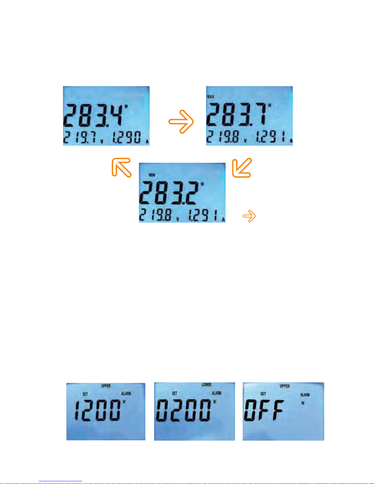
6-2-1. WATTS Screen Mode:
●
Press the SELECT button can show the detail of
MAX/MIN on the display.
●
SET Alarm
Press the SET button can set watt alarm to the
upper/lower limit mode.
Press the SELECT button can change the upper or
lower limit.
Press the MODE button can change flashing number
position.
Press the RESET(▲) button to increase the flashing
digit (0→9).
Press the SET(▼) button to decrease the flashing
digit (9→0).
Press the RUN/STOP button to confirm the setting
number.
: Press the SELECT button
can see MAX/M N watts.
-9-
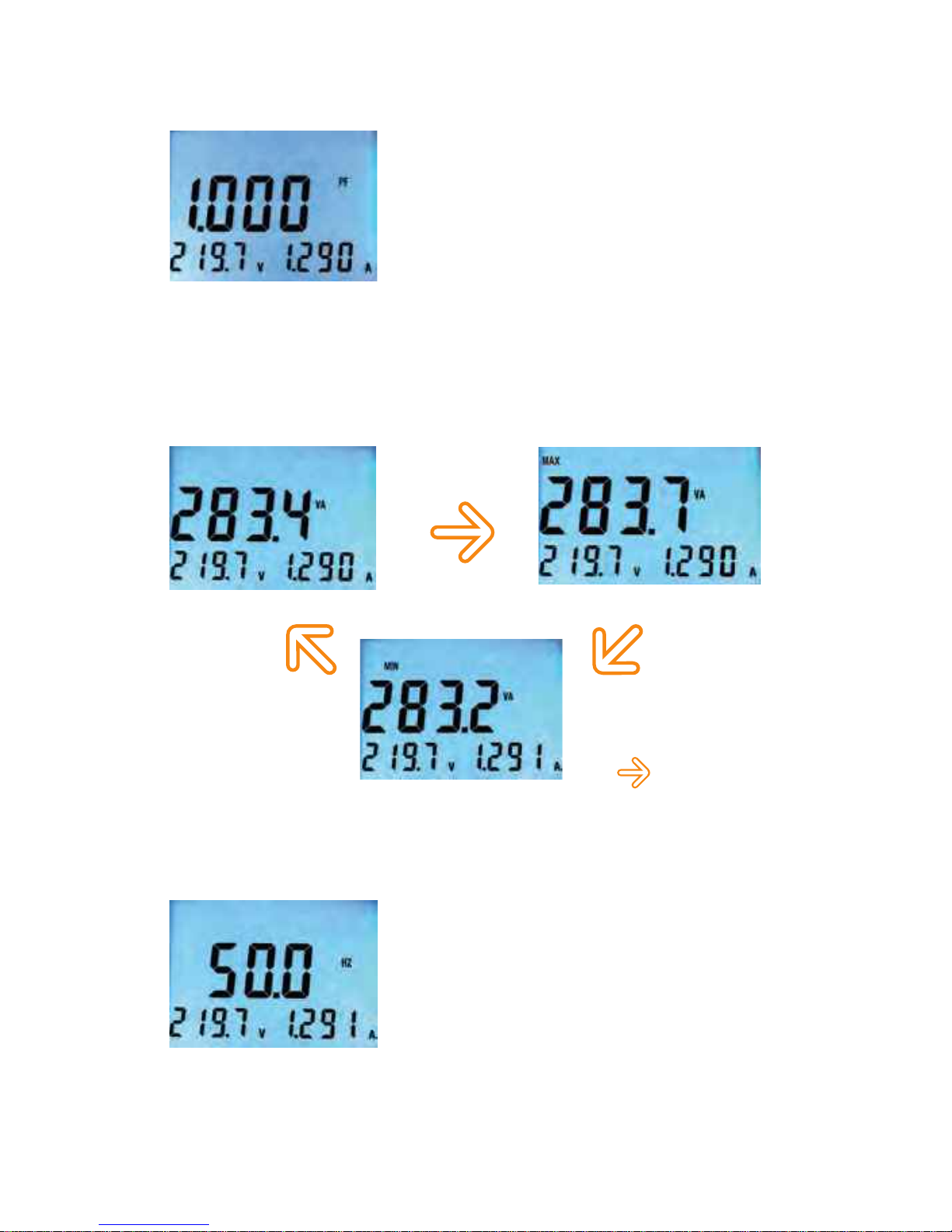
6-2-2. POWER FACTOR Screen Mode :
6-2-3. Apparent Power Screen Mode :
●
Press the SELECT button can show the detail of
MAX/MIN on the display.
6-2-4. Frequency Screen Mode :
: Press the SELECT button
can see MAX/MIN apparent
power.
 Loading...