

Page 1

BST-MG08/09 Multi-gas Detecting Alarm
Manual Instruction
1. Application: This product is designed to ensure sa fety for users who work in dangerous
places. It’s used for detecting CO, O2, H2S, CH4 simultaneously and alarm users by light,
sound and vibration. This device is portable, anti-explosion and intrinsically safe.
2.
Features:
1. Measured gases: Combustible Gas(LEL/CH4), Oxygen(O2), Carbon Monoxide(CO), and
Hydrogen Sulfide(H2S). Contact manufacturer f
or other gas combinations.
2. It will alarm users by sound, vibration, and light with different intensity if actual
concentration is higher or lower than preset alarm points.
3.
Operation:
1. 4 buttons included.
On/Off button; OK button; ▲Up button; ▼Down button
2. Long press
On/Off button to activate the device. It will show below information in
turn:
A. Product brand
B. Low Alarm [L]
C. High Alarm [H]
D. STEL Alarm [S]
E. TWA Alarm [T]
F. Preset Calibration Value
G. Product number and next calibrate date, 30 seconds countdown
H. Auto Zero option
3. In auto zero option, after seeing “Adjust Zero?”, long press “OK” button to zero all
sensors, short press “
” button to exit. When the device is zeroed in unfresh air, the
system will zero itself when the device is back to fresh air, n o need to worry about the
accuracy.
4. In main interface, it shows 4 alarm icons on top area: [L], [H], [S], [T], if there is any alarm,
the corresponding icon will turn red. Short press “▲” to switch among STEL, TWA, PEAK,
and MIN. No operation for 30 seconds will bring it back to main interface.
5. Long press “OK” button to enter function interface.
LOGO
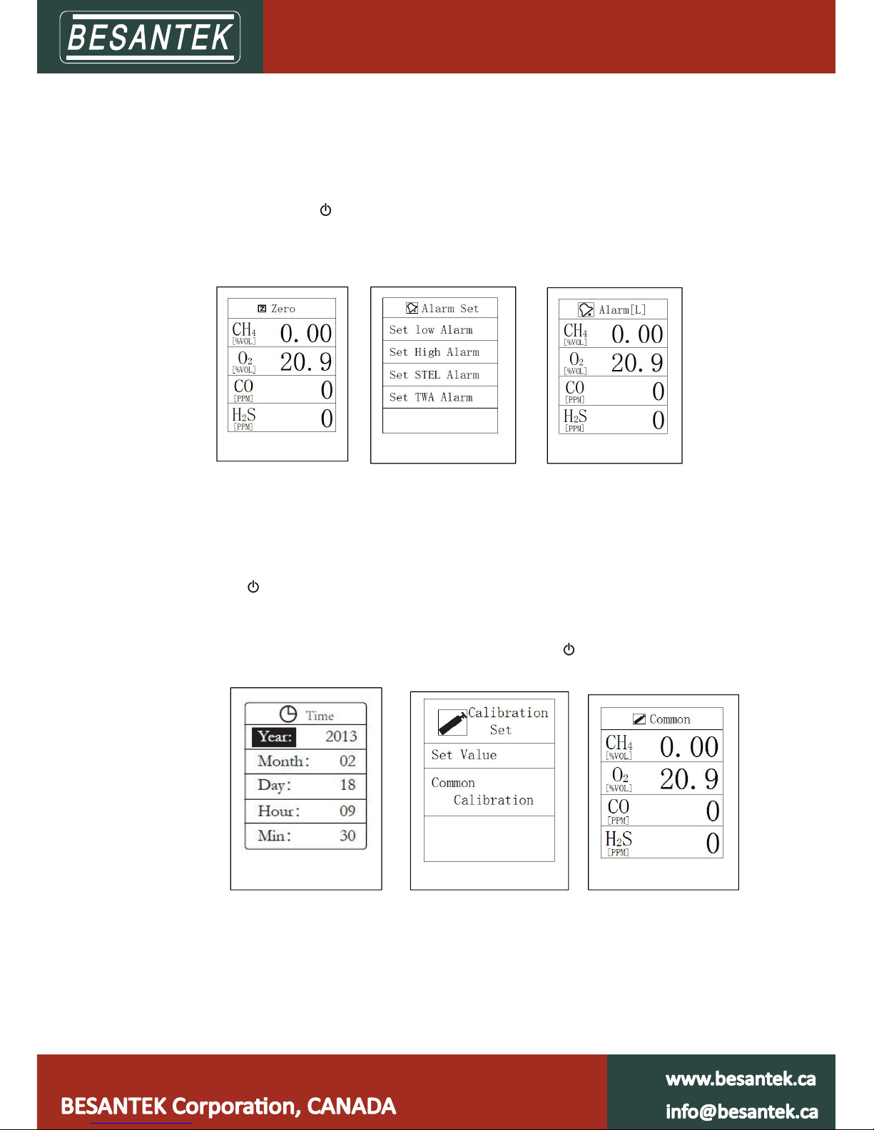
Main Interface
Function interface
Page 2
6. In f unction interface, short press “▲ ” or “▼” to select function, then short press “OK”
button to enter corresponding function.
7. In zero interface, short press “ ▲ ” or “ ▼ ” to select gas, long press “OK” button, the
background of selected gas will turn red, long press “OK” button again to c o mplete the
operation with display “set OK”. If there is no “set OK” showed, it means operation is
failed. Short press “
” to exit.
Notice: Use 100%vol nitrogen gas to zero oxygen sensor, for other sensors, it can be done in
fresh air.
8. In alarm interface, short press “▲” or “ ▼” to select among “Set Low Alarm”, “Set High
Alarm”, “Set STEL Alarm”, and “Set TWA Alarm”. Short press “OK” bu tton to enter each
setting “Alarm[L]”, “Alarm[H]”, “STEL[S]”, “TWA[T]”, short press “▲ ” or “▼ ” to set the
value, long press “OK” button to complete the operation with displ ay “set OK”. Short
press “
” to exit.
9. In time setting interface, short press “OK” button to select “Year”, “Month”, “Day”,
“Hour”, “Min”, then press “▲ ” or “▼ ” to adjust the value. Long press “OK” button to
complete this operation with display of “Set OK”. Short press “
” to exit.
10. In calibration setting interface, short press “▲” or “▼” to select between“Set Value”
and “Common Calibration”
A. “Set Value”: user should input available calibration gas concentration here, short
press “OK” button to select among gases and short press “▲ ” or “▼ ” to adjust gas
values, long press “OK” button to complete this setting with display of “Set OK”.
Zero Interface
Alarm Set
Low Alarm setting
Time Setting
Calibration Setting
Common Calibration
Page 3

Important: user should make this setting before following operations.
B. In “Co mmon Calibration” interface, short press “▲” or “▼” to select gas, long press
“OK” button, the background of selected gas will turn red, connect calibration gas
and after the value is stable, long press “OK” button to complete this operation with
display of “Set OK”. Short press “
” to exit.
Notice:
a. Before calibration, a ctivate this device for at least 6 minutes to allow it run stably
b. When the device is alarming for low power, stop calibration and charge it right away
c. Calibration gas must be standard gas used for calibration purpose
d. Zero sensors firstly before calibration
e. Make sure gas flow is stable before connecting calibration gas, calibration gas flow for CH4,
CO, O2 is 200ml/min, 300ml/min for H2S.
f. Suggested calibration gases are
as following:
CH4 1.00%vol, CO 500ppm, H2S 50ppm, oxygen can be calibrated in fresh air
11. In setting interface, short press “ ▲ ” or “ ▼ ” to select among “CH4”, “LEL”, “PPM”,
“MG/m³ ”, “Allow Calibration”, “√ ” means item is selected. Long press “OK” button to
select a nd confirm. Short press “
” to exit.
Important: User can’t enter calibration i nterface without choosing “Allow Calibration”
4.
Technical Parameter:
Technical
Specification
Parameter
Measured gas Methane(CH4), Oxygen(O2),
Carbon Monoxide(CO), Hydrogen Sulfide(H2S)
Methane (CH4)
Measurement range (0.00~5.00)%vol
Measurement error
(0.00~1.00)%vol: ±0.10%CH4
(1.00~3.00)%vol: True value±10%
(3.00-5.00)%vol: ±0.30%CH4
Respond time
≤20s (T90)
Resolution
0.01%vol Alarm point
1.0
0%vol (Adjustable for full
range)
Oxygen (O2)
Measurement range (0.0~30.0)%vol
Measurement error
(0.0~5.0)%vol: O2:±0.5%vol
(>5.0~30.0)%vol: O2:0.9%vol
Respond time
≤35s (T90)
Resolution
0.1%vol Alarm point
18.0%vol(Adjustable for full range)
25.0%vol(Adjustable for full range)
Carbon Monoxide (CO)
Measurement range (0~1000)ppm
Measurement error
(0~20)ppm:±2ppm
(>20~100)ppm:±4ppm
Page 4

(>100~500)ppm: True Value±5%
(>500~1000)ppm:True value±6%
Respond time
≤
45s (T90)
Resolution 1p pm Alarm point 24%vol(Adjustable for full range)
Hydrogen Sulfide (H2S)
Measurement range (0~100)ppm
Measurement error
(0~50)ppm:±3ppm
(>50~100)ppm: ±10%
Respond time
≤45s (T90)
Resolution 1p pm Alarm point 10ppm(Adjustable for full range)
Sensor lifetime
CH4:≥1 year
CO,H2S,O2:≥2 years
Alarms
Audible--buzzer with ≥85dB @1m audible
Visible--flashing red LED, ≥
20m visible
Vibration
Charging time 4-5hours
Continuous operating
hours
13 hours
Battery model PL123450, 3.7V/1500mA
Protect Grade IP66
Working temperature
-25
℃
~
50
℃
Size(mm) 130*70*37
Data logging for
MG08 only
Continuously data logging
(100000 records with 1-10 minutes interval)
Enclosure
PC+ABS with resistance ≤10
-9
Ω
Display Color Screen LCD
≥
Safety Standard:
- CE: EN 50270:2006
MA/KA: GB3836-2010
EX: GB3836.1-2010 & 3836.4-2010
Page 5

External Sampling Pump
Manual Instruction
Product description:
This gas sampling pump can be used with any portable gas detectors, and detect target
gas as far as 30 meters. With 4 LED indicators, user can know power left easily.
Technical parameter:
Sampling Air Flow
Sampling Distance
Working Temperature
Working Humidity
Power Source
Output
Input
Charging Time
Weight
How to turn ON and OFF this pump:
Long press power switch to activate this pump and long press power switch again to
shut it off.
1600ml/min
30m
-20~50�
≤90%RH
3.7V rechargeable lithium battery
5W
DC5V 1A
8h
200g
Page 6

Gas Check User’s Guide
1. Gas Detector Data Collection Setting
1.1. Activate gas detector by long pressing button.
1.2. Long press OK button to function interface
1.3. Press up/down button and choose “Setting”, enter it by short pressing OK button
1.4. Press up/down button and choose “Data Store”,enter it by short pressing OK button
Use: The amount of data have been collected & stored
Total: Total amount of data can be collected & stored
Time: Configurable time interval between 1-600s for data collection
Stop: Stop data collection. Short press
button to confirm.
Start: Start data collection. Short press OK button to switch between “Stop” and “Start”, long press OK
button to confirm.
OK button to switch between “Stop” and “Start”, long press OK
1.5. After well setted, user can find
storing data.
Notice: when gas detector is connected with Gascheck software for real-time data collection, gas detector
data collection will be out of work.
on top of detecting interface, which means device is collecting&
2. Gascheck Driver and Software Installation
2.1. Open CD-Rom Driver on your computer and put the offered CD into it
2.2. Read the CD and find
OS.
2.3. Double click “PreInstaller.exe” or “CP210xVCPInstaller.exe” and click “Install”, then you’ll see
window prompt with “Installation Successfully”.
2.4. To confirm this driver has been installed successfully: right click “My Computer”and choose “Device
manager “ and unfold “Port (COM and LPT)” you’ll find “silicon Labs CP210× USB toUART Bridge”.
2.5. Find “Gas Check Setup”, install this software by dou
for installation
Notice: Before connecting gas detector with Gascheck software, please install driver firstly, or gas
detector can’t be recognised by software.
Gas Check Driver programme, then choose right file according to your computer
ble clicking this setup, follow window prompt
3. Gascheck operation
3.1. Double click “Gas Check” icon on your desktop, and connect with activated gas detector using USB
cable.
3.2. Click “Connect”to connect gas detector with this software, after well connected, status wi
“Connected”and model number will come out.
ll become
Page 7

3.3. After connection, date and time on gas detector will synchronize automatically with computer.
“Real-time” is for collecting real-time data, these data will only store on computer, check&analyze these
data on “Data show” section “Real-time data”.
“History data” is for checking data collected by gas detector or data have been stored on computer
A. Real-time data collection and checking
1. Click “Modify” to set interval time from 1-10 min, click “Save”to confirm.
2. Switch “Real-time” ON, you’ll get real-time data and they will be shown on “Show Data” chart.
3. Stop real-time data collection by switching OFF.
B. Gas detector data collection and checking
1. Click “Get data” to get data collected by device, time needed is 1-6 minutes, device will show
“Loading” during this period.
2. Check&analyze these data on “Data show” section “History data”.
3. This software can get and store data from several gas detectors, when data acquisition finished for one
device, click “Disconnect” and connect with another one.
4. Click “Clear data
” to delete all data collected by gas detector
5. When collecting data by device, user has 2 operation methods
a. Set device following “Gas detector data collection setting”
b. Set “Device setting” on software
1)Set valid start and stop time, click “Modify” to set time interval from 1-10m, then click “Save” to
finish.
2)User will find
on top of detecting interface, which means device is collecting& storing data.
3)Accident power ON or OFF during start and stop time will not affect data collection, after restarting,
data collection will go on .
3.4. “Show data” section
Tick the colorful boxes to choose gases needed to be shown up on chart.
“Real-time data” is for real-time collected data.
Page 8

“History data” is for data collected by gas detector and data have been stored on computer.
“Select device” to see available history data of a certain gas detector.
“DEL” is to delete just model number of gas detectors which have been registered on this computer, this
function is for a better management of more than one gas detector you use. When you register it the
second time, you’ll find all history data.
r can also check data in a certain day by setting start-stop time, start and stop time need to be in same
Use
day; if not, you’ll get min, ave, max values for each gas and each day.
Place mouse pointer on any point of collected data curve, you’ll get exact time and concentration of this
data.
Press left mouse and drag from left to right to spread all detailed data points, and drag from right to left to
pull back, o
r click cross point of x and y axises to pull back.
On right side of the chart, you’ll find 3 gas analyzing circle diagrams with “Avg”
“Min””Max”, tick circles below to see analysis for each gas.
Click “Disconnect” to disconnect this gas detector with software, status will become:
Disconnected
Click “Export” to export data in excel format.
 Loading...