

Besantek BST-GFL31 User Manual

BESANTEK BST-GFL31 Ground-Fault Locator
User Manual
P-140313-V1.5
Test Equipment Depot - 800.517.8431 - 99 Washington Street Melrose, MA 02176
TestEquipmentDepot.com

Catalog
BST-GFL31 User Manual
1. ABOUT
2. MAIN OPERATION OF BST-GFL31 ............................................................................................................... 8
3. OTHER SETTINGS OF GENERATOR AND RECEIVER ............................................................................. 23
BST-GFL31
1.1 BST-GFL31 Brief Information? ............................................................................................................... 2
1.2 BST-GFL31 Main Functions ................................................................................................................... 2
1.2.1 Ground Fault Location ................................................................................................................. 2
1.2.2 Frequency Spectrum Analysis ..................................................................................................... 2
1.2.3 Oscilloscope ................................................................................................................................ 2
1.3 Features ................................................................................................................................................. 2
1.4 Typical Application .................................................................................................................................. 3
1.5 Technical Specification ........................................................................................................................... 3
1.6 Composition of BST-GFL31 ................................................................................................................... 3
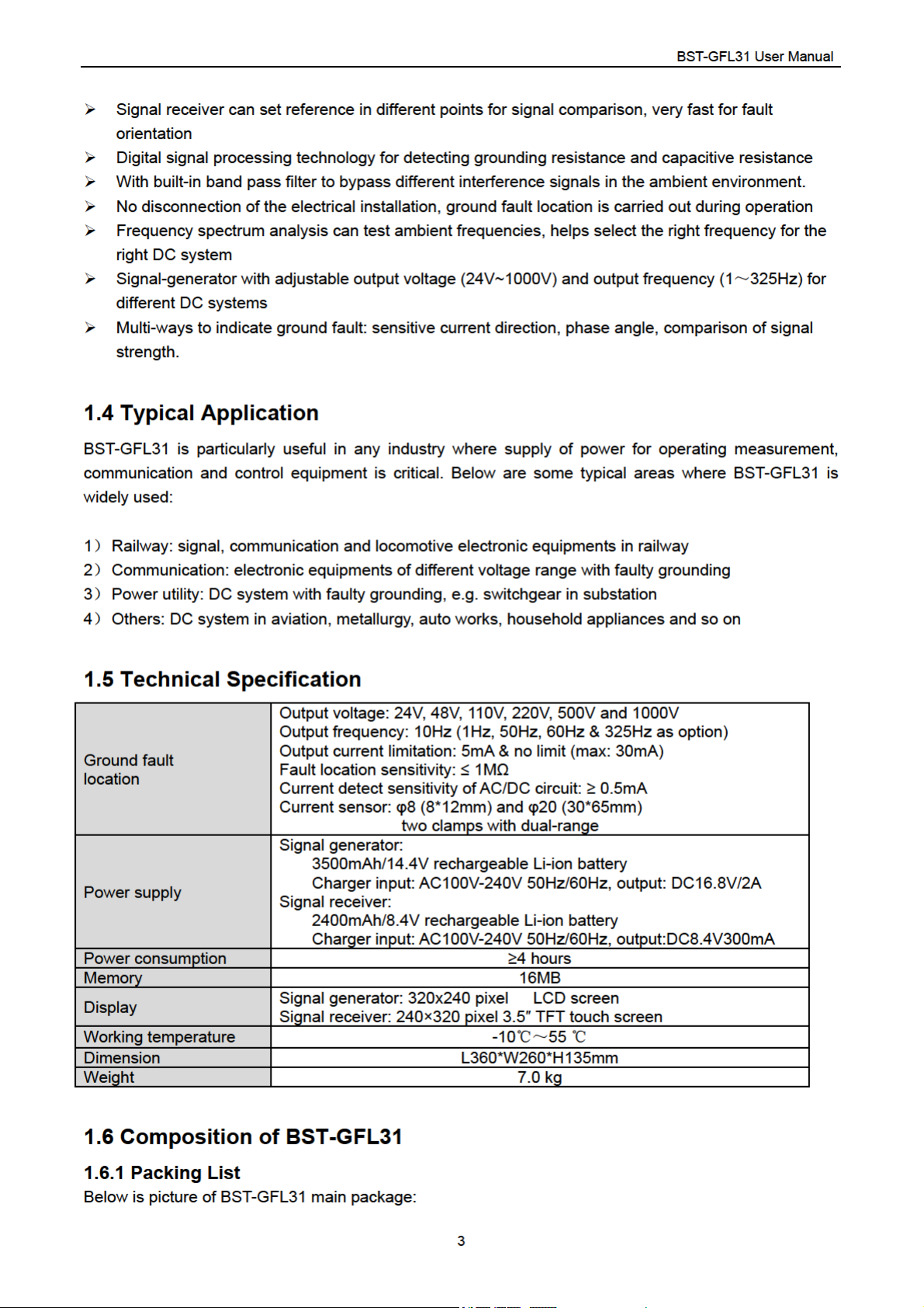
1.6.1 Packing List ................................................................................................................................. 3
1.6.2 BST-GFL31 Main Body ............................................................................................................... 4
1.6.3 Signal Receiver ........................................................................................................................... 5
1.7 Basic Concepts ...................................................................................................................................... 6
1.7.1 About Faulty Grounding ............................................................................................................... 6
1.7.2 Wire Mix-connection .................................................................................................................... 7
1.7.3 Short circuit .................................................................................................................................. 8
1.7.4 Current leakage ........................................................................................................................... 8
1.7.5 Tracing of Current Signal ............................................................................................................. 8
2.1 General Steps for Fault Location ........................................................................................................... 8
2.2 Operation Preparation ............................................................................................................................ 9
2.3 Wire connection with DC System ........................................................................................................... 9
2.4 Set Generator Output Signal ................................................................................................................ 10
2.4.1 Measurement of Circuit ............................................................................................................. 10
2.4.2 Output Signal Adjustment .......................................................................................................... 11
2.4.3 Output Signal to Circuit for Fault Location ................................................................................ 12
2.4.4 Return Circuit for Fault Location ................................................................................................ 13
2.5 Signal Tracing with Signal Receiver ..................................................................................................... 13
2.5.1 Frequency Synchronization ....................................................................................................... 13
2.5.2 Set Signal Reference ................................................................................................................ 14
2.5.3 How to Locate Ground Fault? ................................................................................................... 17
2.6 Some Tips for Ground Fault Location .................................................................................................. 18
2.6.1 Multiple Setting of Signal Reference ......................................................................................... 18
2.6.2 Gross searching ........................................................................................................................ 20
2.6.3 Use more than one signal receiver ............................................................................................ 20
2.7 Signal Changes in Eart
2.8 Location for Other W
2.8.1 Wire Mix-connection .................................................................................................................. 21
2.8.2 Short-circuit Fault Location ........................................................................................................ 22
2.9 About Distributed Capacitance ............................................................................................................. 22
........................................................................................................................................ 2
h Fault Circuit .................................................................................................. 20
ays of Fault ......................................................................................................... 21
1

BST-GFL31 User Manual
3.1 Signal Generator Setting ...................................................................................................................... 23
3.1.1 Set Date & Time ........................................................................................................................ 23
3.1.2 Parameter Setting...................................................................................................................... 23
3.1.3 Firmware Version....................................................................................................................... 24
3.2 Signal Receiver Functions and Settings .............................................................................................. 24
3.2.1 Frequency Spectrum Analysis ................................................................................................... 24
3.2.2 Oscilloscope .............................................................................................................................. 26
3.2.3 System Setting .......................................................................................................................... 26
4. SERVICE & MAINTENANCE ........................................................................................................................ 28
4.1 Self-Check ............................................................................................................................................ 28
4.2 FAQ ...................................................................................................................................................... 29
4.3 Cleaning & Storage .............................................................................................................................. 30
4.3.1 Cleaning .................................................................................................................................... 30
4.3.2 Storage ...................................................................................................................................... 30
5. CONTACT BESANTEK ................................................................................................................................. 30
2

▲Safety Information
For your protection, please read this safety information completely before operating the locator. Carefully
observe all warnings, precautions and instructions.
WAR NING: Service information described in this manual is to be done by qualified personnel only. To
avoid electrical shock or equipment damage, do not service the instrument unless you are qualified and
with BESANTEK’s instruction.
Safety testing has been done on this instrument thoroughly
DANGER
before shipment. However, mishandling during use could
result in injury or other bad consequences, as well as damage
to the instrument. Make sure that you understand the
instructions and precautions in the manual before use. We
disclaim any responsibility for accidents or injuries not resulted
directly from instrument defects.
Safety Symbols
Description of symbols used in this manual.
WAR NING Indicates correct operation to prevent a significant hazard that
could result in serious injury or other bad consequences to
users or instrument.
NOTE Indicates advisory items related to performance or correct
operation of the instrument.
▲Operating Precautions
To avoid ele
ctrical shock
or fire, read these precautions first before using the locator:
Except as explained in this manual, do not attempt to service this equipment yourself.
Do not operate the equipment around explosive gas or vapor.
Only use BESANTEK’s testing leads and other relative accessories with the locator.
Before use, inspect the locator, testing leads and other accessories for mechanical damage and
replace if necessary. Pay special attention to the insulation surrounding the connectors.
Remove all clamps, testing leads and accessories that are not in use.
Do not apply the instrument in other purposes that are not described in this user manual
Ensure the equipment is provided with adequate ventilation.
This manual describes the general operation of the testing system. If your system has features or
accessories not addressed in this manual, please contact your supplier.
Only qualified technicians are allowed to use the equipment. For fast ground fault location, it will be
very important and necessary to familiarize the tested environment, especially the wiring structure of
the target site.
Test Equipment Depot - 800.517.8431 - 99 Washington Street Melrose, MA 02176
TestEquipmentDepot.com

BST-GFL31 User Manual
1. ABOUT BST-GFL31
1.1 BST-GFL31 Brief Information?
BST-GFL31 is BESANTEK’s new generation of ground fault locator applied with advanced technique
for earth fault detection. This patent-protected product is built based on years of field experience in
different DC systems. It specially deals with current leakage in DC system of high grounding resistance
below 1MΩ. Without switching off the DC system, it pinpoints faulty grounding online where electrical
lines have breakage and current lost to the ground. It gives excellent solutions for troubleshooting and
preventative maintenance.
Compact and rugged design makes the BST-GFL31 easy to use in small places and harsh environment.
1.2 BST-GFL31 Main Functions
1.2.1 Ground Fault Location
With comprehensive ways including signal strength, phase change and precise judgment for leakage
current direction, it fast pinpoints ground fault.
Based on different distributing capacitance, it selects the right output frequency for testing, which
enables it to be widely used in different DC systems.
Output voltage of signal generator
selectable among 24V, 48V, 110V, 220V, 500V and 1000V. This will meet requirement for various
electric circuit of different voltage levels without interference to the circuit.
Output current of signal generator
5mA and unlimited current (limited power with max output current of 30mA). It is selected as per
different systems, preventing from incorrect operation of circuit relay.
Output frequency of signal generator: Standard 10Hz and with options of 1.0Hz, 50Hz, 60Hz and
325Hz which are selectable based on different DC systems.
:
:
1.2.2 Frequency Spectrum Analysis
It effectively analyzes the working signal and surrounding interferences signals of DC system. This will
help to select the right output frequency for ground fault location and avoid interference by the
surrounding signals.
1.2.3 Oscilloscope
It checks waveform of target signal.
1.3 Features
Patented technology, pinpoint current leakage fault with grounding resistance lower than 1MΩ
Innovative dual-clamp for signal receiver, each clamp has two sizes of opening jaw for different
conductors
One pair of clamp working together, effective cancel capacitive interference when system is online
Precise current direction (positive or reversed) indicating for leaking current help fast locate the
faulty grounding
Adjustable output frequency on signal receiver effectively avoids interference from DC system itself
2
BST-GFL31 User Manual
Fig. 1.6.1
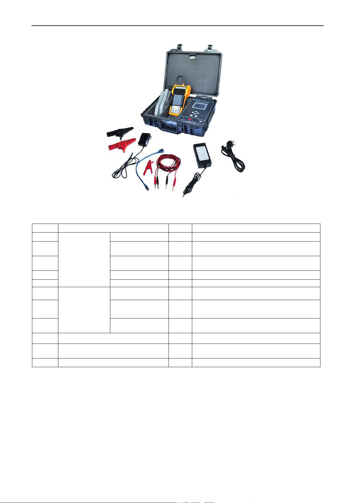
Full packing list:
Item Parts No. NOTE
1
2 Power adaptor 1
3 Signal testing lead 2
Main body
(in molding
case)
Signal generator 1
Input: AC110V/220V
Output:16.8VDC/2A
One red and one black
2.5m long each
4 Alligator clip 2 One red and one black
5 Puncture clip 1 Red
6
7
Standard signal
receiver
8 Power adaptor 1
Signal receiver 1
Dual-range
current detector
2
One pair, dual-range (φ8 and φ20)
With 150cm long lead
Input: AC110V/220V
Output: 8.4VDC/300mA
9 User manual 1 This manual
10 USB drive 1
With backup firmware, software and user
manual
11 Qualification certificate 1
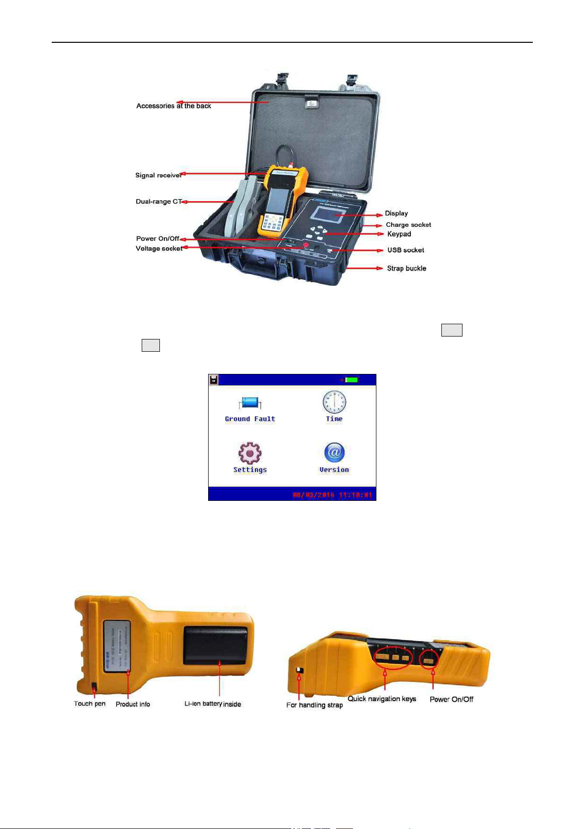
1.6.2 BST-GFL31 Main Body
Below is picture of BST-GFL31 main body and functionality of each part.
Test Equipment Depot - 800.517.8431 - 99 Washington Street Melrose, MA 02176
TestEquipmentDepot.com
4
BST-GFL31 User Manual
Fig 1.6.2.1
After turning on the On/Off switch, press any key on the keypad to continue and you will see the main
menu as below for each function. Use the arrow keys to highlight each and press ENT to confirm the
selection or press Esc to go back. Main body function and setting will be introduced in detail in this
manual later.
Fig 1.6.2.2
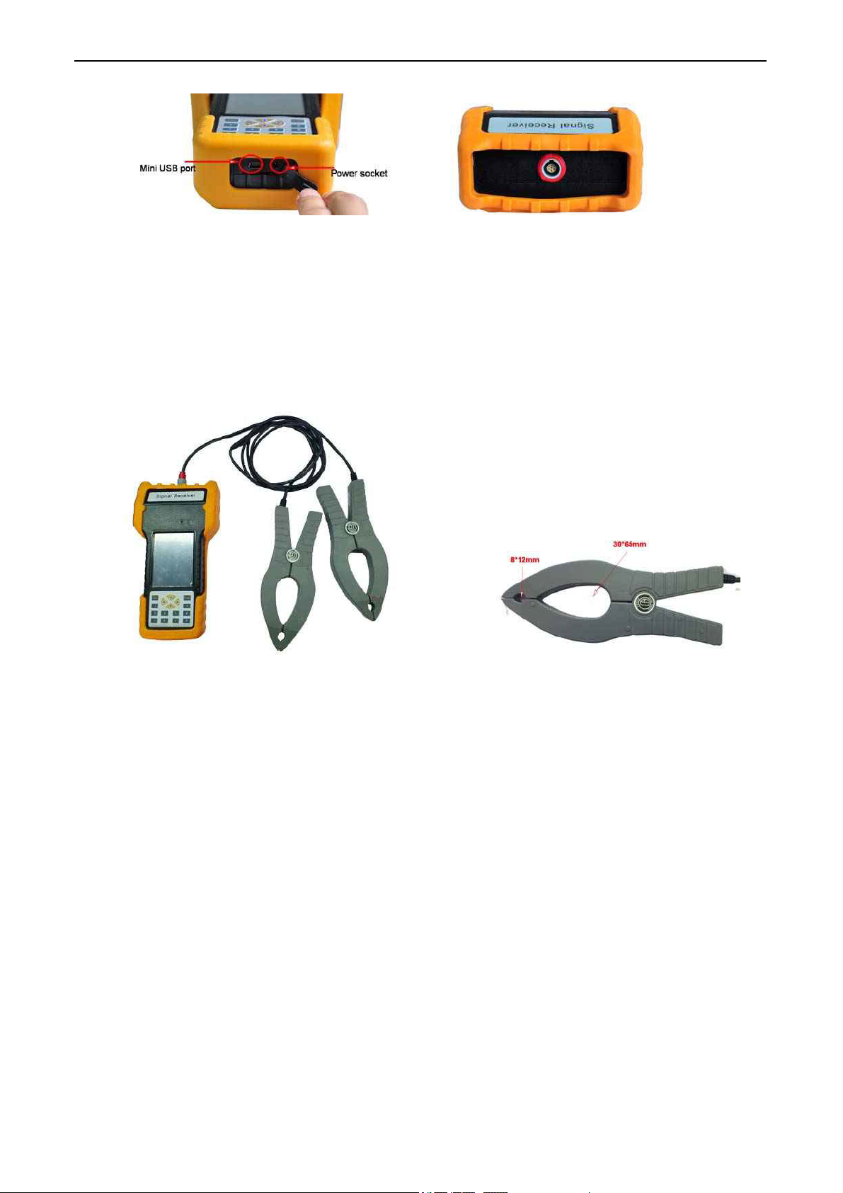
1.6.3 Signal Receiver
All standard units will come with standard signal receiver and one pair of dual-range current detector.
Signal Receiver Main Body:
Back Side
5
BST-GFL31 User Manual
Bottom Top for current detector
Fig 1.6.3
Standard signal receiver could be operated by touch screen, keypad or quick navigation keys at side.
After switching on the unit, you will see the main functions including ground fault location, frequency
spectrum analysis, oscilloscope and system setting. We will introduce these functions in detail in the
following context.
Current Detector:
Fig 1.6.3.1 Fig 1.6.3.2 Current detectors
Signal receiver main body will be connected with one pair of dual-range current detector like Fig 1.6.3.1.
BESANTEK’s innovative designing of dual-range current detector (CT) has 2 different sizes of opening
jaw (8*12mm and 30*65mm). Depending on different size of wire or conductors, you could selectively
clamp with either size of jaw which have the same effect.
Also, with one pair of current detectors working at the same time in the circuit, BST-GFL31 will have
strong capability for anti-interference. Therefore, it could check ground fault effectively even when
system is online without switching off the DC system.
Each current detector has labels of arrow mark at both sides. The arrow marks are used for current
direction indication during ground fault location. For detailed operation instruction of dual-range current
detector, please refer to Section “2.5 Signal Tracing with Signal Receiver”.
1.7 Basic Concepts
1.7.1 About Faulty Grounding
AC or DC power systems are generally insulated to the ground in railway electric works, power
substation, telecom base station and the alike. There are also clear and strict rules for insulating
resistance in different voltage levels of AC or DC power systems.
And it is generally considered as the phenomenon of faulty “Grounding” when grounding resistance of
6
BST-GFL31 User Manual
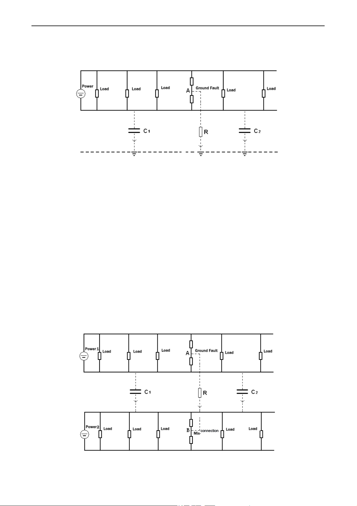
one point (or multi-points) becomes lower than tolerance value. Take following chart for example, Point A
is the grounding point, R is the grounding resistance, C1 and C2 indicate distributed capacitances before
and after the malfunction point.
Fig 1.7.1
When one point of circuit has unwanted grounding like this, protection equipments, signaling equipments
and automation equipments may have incorrect operation or may stop running, or fuse will burn out and
thus cut off power supply for protection equipments, automation equipments, controlling circuit and
communication signaling system.
If one point problem is unsolved for long time until more points have the same problem, it may damage
electronic circuit or equipments. Therefore, unwanted grounding of electronic circuit is very big hidden
danger. Therefore, a fast detection of ground fault will be very necessary before “small” problem
becomes big accident.
1.7.2 Wire Mix-connection
Sometimes two or more groups of power systems are working simultaneously, and normally they are
insulated from each other. When insulating resistance between these individual powers become lower
than required value in one point or more points, we call it as “wire mix-connection”. Below is one
example. Point A and B are malfunction points. R indicates the mix-connection resistance. C1 and C2
indicate the distributed capacitances.
Wire mix-connection is common problem in signaling system in railway. It also has big hidden hazard like
faulty grounding.
Fig 1.7.2
7
 Loading...