

Besantek BST-DL102, BST-DL103, BST-DL104 User Manual
BST-DL102 / BST-DL103 / BST-DL104
Multi-Channel Thermocouple Thermometer User Manual

CONTENTS
Chapter 1. BST-DL102 / BST-DL103 / BST-DL104 80X Hardware
........................................................................ . .
1
1.1 Introduction
........................................................................ . . . . . . . . . . . . . . . . . . . . . . . . . . . . . . . . . . . . . . . . . . . . . . . . . . . . . . . . . . . . . . . . . . . . . . . . . . . . . . . . . . . . . . . . . .
1
1.2 Application
........................................................................ . . . .
........................................................................ . . . . . . . . . . . . . . . .
1
1.3 Multi-channel Thermocouple Therm ometers Model
........................................................................ . . . . . . . . . . . . . . . . . . . . . . . . . .
1
1.4 Appearance
........................................................................ . . . . . . . . . . . . . . . . . . . . . . . . . . . . . . . . . . . . . . . . . . . . . . . . . . . . . . . . . . . . . . . . . . . . . . . . . . . . . . . . . .
.........
2
1.5 Single-channel LCD Screen (BST-DL102)
........................................................................ . . . . . . . . . . . . . . . . . . . . . . . . . . . . . . . . . . . . . . . . . . . . . . .
3
1.6 Two-channel LCD Screen (BST-DL103)
........................................................................ . . . . . . . . . . . . . . . . . . . . . . . . . . . . . . . . . . . . . . . . . . . . . . . . . .
4
1.7 Four-channel LCD Screen (BST-DL104)
.........................................
........................................................................ . . . . . . . .
5
1.8 Buttons
........................................................................ . . . . . . . . . . . . . . . . . . . . . . . . . . . . . . . . . . . . . . . . . . . . . . . . . . . . . . . . . . . . . . . . . . . . . . . . . . . . . . . . . . . . . . . . . . . . . . . . . .
6
Chapter 2. BST Software
........................................................................ . . . . . . . . . . . . . . . . . . . . . . . . . . . . . . . . . . . . . . . . . . . . . .
...........................
7
2.1 Install Driver & Software
........................................................................ . . . . . . . . . . . . . . . . . . . . . . . . . . . . . . . . . . . . . . . . . . . . . . . . . . . . . . . . . . . . . . . . . . . . . . .
7
2.2 Setting the Logger’s Properties to Start a New Measurement.
........................................................................ . . . . . . . . . . .
8
2.3 Properties Description
.........................................
........................................................................ . . . . . . . . . . . . . . . . . . . . . . . . . . . . . . . . .
9
2.4 Download the Records after a measurement.
........................................................................ . . . . . . . . . . . . . . . . . . . . . . . . . . . . . . . . . . .
10
2.5 Data Listing Window
........................................................................ . . . . . . . . . . . . . . . . . . . . . . . . . . . . . . . . . . . . . . . . . . . . . . . . . . . . . .
.....................
11
2.6 Exporting Logs from Loggpro
........................................................................ . . . . . . . . . . . . . . . . . . . . . . . . . . . . . . . . . . . . . . . . . . . . . . . . . . . . . . . . . . . . . .
11
2.7 Delete records in the logger
........................................................................ . . . . . . . . . . . . . . . . . . . . . . . . . . . . . . . . . . . . . . . . . . . . . . . . . . . . . . . . . . . . . . .
12
2.8 Check the Save File in File List
.....................
........................................................................ . . . . . . . . . . . . . . . . . . . . . . . . . . . . . . . . . . . . . . .
12
Chapter 3. Attention
........................................................................ . . . . . . . . . . . . . . . . . . . . . . . . . . . . . . . . . . . . . . . . . . . . . . . . . . . . . . . . . . . . . . . . . . . . . . . . . . . . . . . .
13
Chapter 4. FAQ
........................................................................ . . . . . . . . . . . . . . . . . . . . . . . . . . . . . . .
..........................................................
14
4.1 LCD Screen Dim
........................................................................ . . . . . . . . . . . . . . . . . . . . . . . . . . . . . . . . . . . . . . . . . . . . . . . . . . . . . . . . . . . . . . . . . . . . . . . . . . . . . . . . . . .
14
4.2 Recording (LOG) are Automatically Stop
........................................................................ . . . . . . . . . . . . . . . . . . . . . . . . . . . . . . . . . . . . . . . . . . . .
14
4.3 Software "R
untime Error"
........................................................................ . . . . . . . . . . . . . . . . . . . . . . . . . . . . . . . . . . . . . . . . . . . . . . . . . . . . . . . . . . . . . . . . . . .
14
4.4 Check COM Port Number
........................................................................ . . . . . . . . . . . . . . . . . . . . . . . . . . . . . . . . . . . . . . . . . . . . . . . . . . . . . . . . . . . . . . . . . . .
14
1
Chapter 1. BST-DL102 / BST-DL103 / BST-DL104 Hardware
1.1 Introduction
BST-DL102 / BST-DL103 / BST-DL104 are thermocouple thermometers, have proved the stability and the
reliability. It enjoys elegant appearance, large LCD display, backlight function and USB port telecommunication.
Besides, it can support 8 types thermocouple sensors (such as K, J, E, T, N, S, R, B), measuring -200degC to
1800degC with different sensor type suitable for the exact applications. BST
-DL102 / BST-DL103 / BST-DL104
with BESANTEK s pecialized BST Software is easy to operate and quite convenient, widely applied in industrial
production fields, food pr ocessing industry, pharmaceutical industry and research testing fields as well as other
temperature monitoring applications.
1.2 Application
Oven
High Temperature Liquid
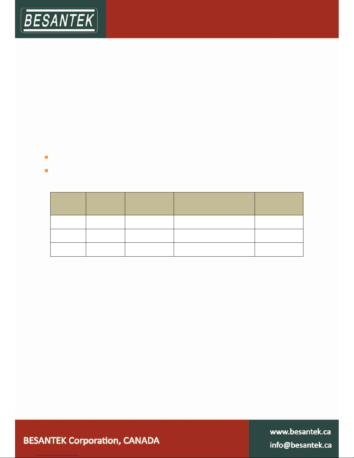
1.3 Multi-channel Thermocouple Thermometers Model
Model
Temperature
channel
Measuring
accuracy
Auto-Recording(LOG-capacity)
Manual-recording
(MEM-capacity)
BST-DL102 1 ±0.1 ‰+0.5℃ 36000 88
BST-DL103 2 ±0.1 ‰+0.5℃ 36000 88
BST-DL104 4 ±0.1 ‰+0.5℃ 36000 88
Notice: The accuracy on the above table is only the accuracy for thermometer itself. The precision in the
practical applications has relation with the accuracy of thermocouple that customers adopt. Please avo id
adopting inferior thermocouple plug in case of any i terminal damage to thermometers.
2
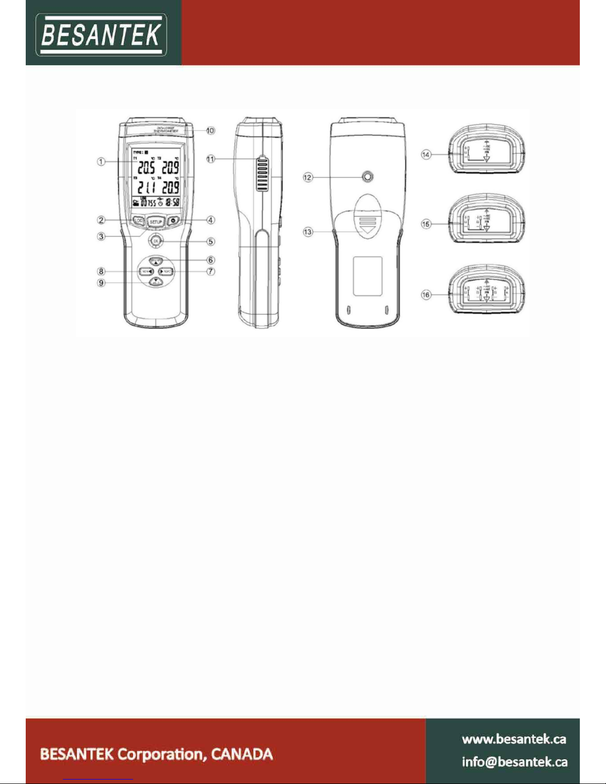
1.4 Appearance
1- LCD display 9- Manual recording function button
2- Log button 10- Model label
3- Setup button 11- USB port & DC power Jack (9V, 3.5mm)
4- ON/OFF 12- Hole for fixed frame
5- OK button under the setup mode, and
backlight button under
normal work ing mode
13- Battery cover
6- Maximum and minimum checking buttons 14- BST-DL102 cap(sensor port)
7- Manual recording data checking button 15- BST-DL103 cap(sensor port)
8- The previous data checking button 16- BST-DL104 cap(sensor p
ort)
3
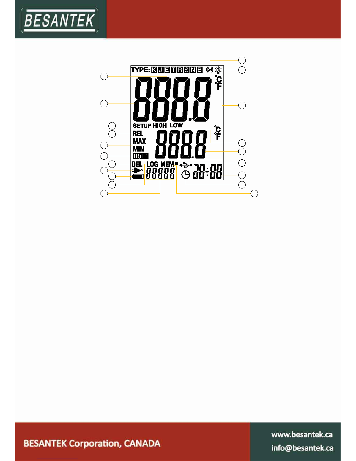
1.5 Single-channel LCD Screen (BST-DL102)
1
2
3
4
5
6
7
8
9
11
10
12
13
14
15
16
18
19
20
17
1- Sensor type symbol display area. 11- Count for auto-recording and manual-recording
data
2- Temperature data display area 12- This symbol shows being the manual-recording
checking status
3- This symbol shows being the setup status 13- Clock symbol
4- This symbol shows being the manual recording
data checking status
14- Time display area
5- This sym bol shows being the maximum and
minimum data checking status
15- This symbol shows instruments being the
connection statu
s with PC.
6- This symbol shows being the holding fixed
measuring data status
16- Maximum and minimum data display area
7- This symbols shows that data can be deleted 17- This symbol shows being the maximum or
minimum data checking status
8- This symbol shows instrument is supported by
external DC power
18- Symbol for temperature unit.
9- Battery status indication 19- This symbol shows being the backlight status.
10- This symbols shows being the logging status. 20- This symbo
l shows the setting limits are being
exceeded.
 Loading...