

Page 1
.,.".--'~-------
----
----...---~
--
.:..........
.
..'
'.
"',
""
.
.
•.•..
""
'S..... ~\
.;
~
Manual
US23-0186-01
Swi
ngmaster@
MP
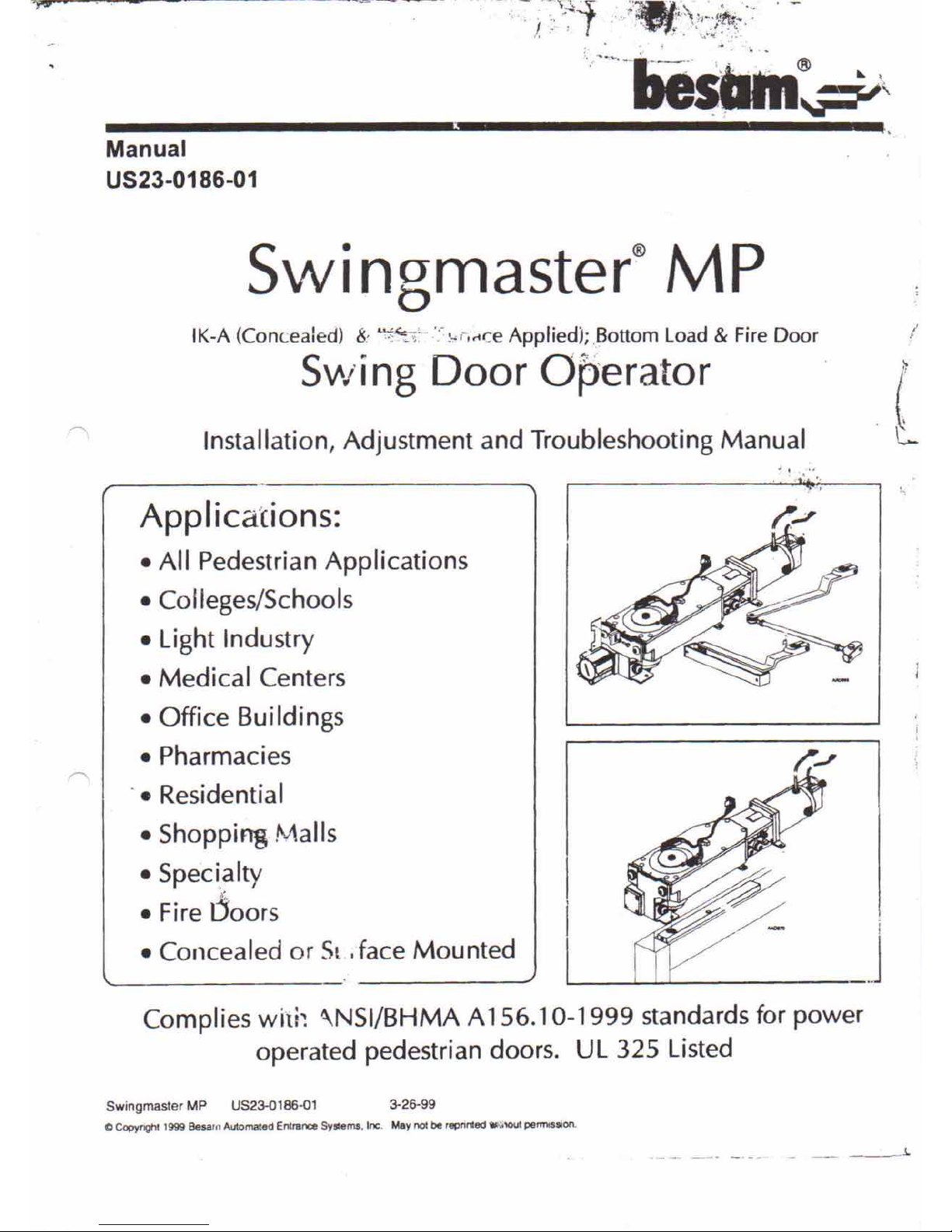
IK-A (Concealed) 8,
~~'<,
l,o,',;.ceApplied); Bottom Load & Fire Door
S\tvi ng
Door Operator
Installation, Adjustment and Troubleshooting Manual
.:,
"
..
i
..
Applications:
• All Pedestrian Applications
• Colleges/Schools
• Light Industry
• Medical Centers
• Office Buildings
• Pharmacies
-• Residential
• Shopping Malls
• Speci,alty
i
• Fire Ooors
• Concealed or Sl;face Mounted
Complies with \NSI/BHMA A 156.10-1999 standards for power
operated pedestrian doors. UL 325 Listed
SwingmaslerMP US23-0186-01 3-26-99
C CopyrlQh! 1999 Besarll AUlomated Enlrance Systems. Inc. May not be repnrfed .':'\OUt pem'llssion.
._ ..•. _'" _..... _ ,__ , __ ..l.
Page 2
Wiring The CUP Control Unit
. {N
Mains L
power Ql
000
- ---- -=- -=-----
-=-
-=---.,./
Note! Only replace
fuses with those of
same rating.
PMO Note! Always enter PIN code first after connecting PMD.
(j)
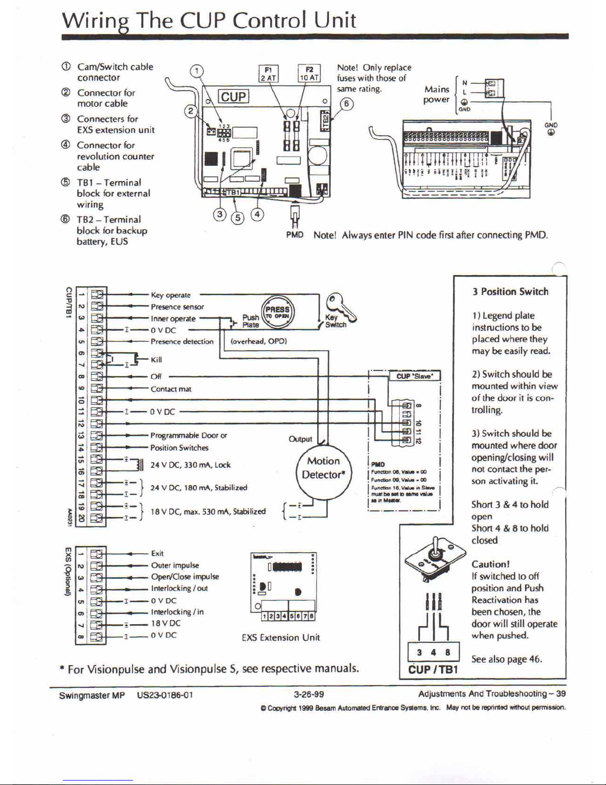
Cam/Switch cable
connector
@
Connector for
motor cable
(ID
Con necters for
EXSextension unit
@
Connector for
revolution counter
cable
@
TBl - Terminal
block for external
wiring
@
TB2 - Terminal
block for backup
battery, EUS
• For Visionpulse and Visionpulse 5, see respective manuals.
3 Position Switch
1) legend plate
instructions to be
placed where they
may be easily read.
2) Switch should be
mounted within view
of the door it is con-
trolling.
3) Switch shou Id be
mounted where door
openingfclosing will
not contact the per-
son activating
it.
r
See also page 4&.
IIJ
rl~
13
4 8
I
CUP/TBl
Short 3 & 4 to hold
open
Short 4 & 8 to hold
<$>
c10sed
Q
Q'"
Caution!
If switched to off
position and Push
Reactivation has
been chosen, the
door will still operate
when pushed.
CUP
"S1a ••••"
i
i
i
i
= 1
1
;;l
i
!
PlIO
i
I
Functioll 08.
Viii"" • OJ
I'
• F",nctiotI OQ,
VIII ••• 00
I
FlIftC'lion 1e,
V.u. ill
s •••••
I'
• f'IlU*tbll •• lOaIM ••••••
!.:.~::~~._._j
~
Switch
12345078
•.•....
D_
o
i
10
0=
1
EXS Extension Unit
(overhead. OPO)
Kill
Key operate
Presence senSOf
Inner operate
I--OVDC
Presence detection
Off
I
Contact mat
Exit
Outer impulse
OperVCioseimpulse
InterlockingIout
I--OVDC
Interlocking I in
, __ 18VDC
!__
OVDC
1--0VDC
Programmable Door
0(
Position Switches
i
II
24 V DC, 330 mA, Lock
~=}
24 V DC. 180 rnA, Stabilized
~::} 18 V DC, max. 530 rnA, Stabilized
(")
c:
..,
~
'"
'"
<-
'"
0>
...
'"
.,
<;;
=
~
'"
<Z
:;:
'"
0;
::;
c;
i
iC
~
m
~
x
en
i
'"
'"
••
<-
-='
'"
0>
...
'"
Swingmaster MP US23-0186-Ql
3-26-99
Adjustments And Troubleshooting - 39
o
Copyrigl1: 1999
Besam
Automa1ed Entrance
Syllems,
toe.
May
not
be reprinted
withOut
pemission.
Page 3
Adjusting The CUP Control Unit
Important Notice!
The 5wingmaster, when installed and set up correctly, is a safe automatic power door oper-
ator, but incorrect settings can defeat its purpose and create a safety hazard. For safety rea-
sons, never set the opening or closing speed faster than necessary to handle the traffic situa-
tion through your door. Please refer to the AN51/BHMA A156.10 - 1999 excerpt in this manual
(page 53). A correctly adjusted door is a safe door!
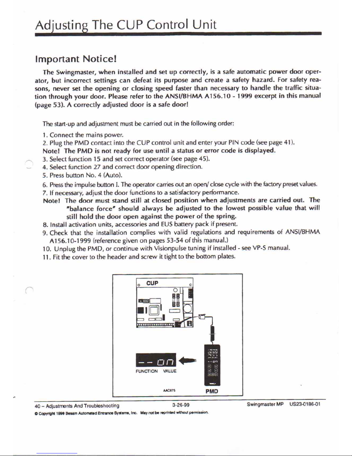
The start-up and adjustment must be carried out in the following order:
1. Connect the mains power.
2. Plug the PMD contact into the CUP control unit and enter your PIN code (see page 41).
Notel The PMD is not ready for use until a status or error code is displayed.
3. Select function 15 and set correct operator (see page 45).
4. Select function 27 and correct door opening direction.
5. Press button NO.4 (Auto).
6. Pressthe impulse button l. The operator carries out an open! close cycle with the factory preset values.
7. If necessary, adjust the door functions to a satisfactory performance.
Notel The door must stand still at closed position when adjustments are carried out. The
"balance force" should always be adjusted to the lowest possible value that will
still hold the door open against the power of the spring.
8. Install activation units, accessories and EUS battery pack if present.
9. Check that the installation complies with valid regulations and requirements of ANSI/BHMA
A156.10-1999 (reference given on pages 53-54 of this manual.)
10. Unplug the PMD, or continue with Visionpulse tuning if installed - see VP-S manual.
11. Fit the cover to the header and screw it tight to the bottom plates.
o
cUP
=
- - on
FUNCTION VALUE
PMD
40 - AdjustmentsAndTroubleshooting 3-26-99
o
CopyTighl tOOt Beum
Automated
Entrance
Syttems, Inc.
May
not be NPrirMd
withOlJt
permiuion.
SwingmasterMP US23'()186'()1
Page 4
Wiring
0p.ti.o.n.s _
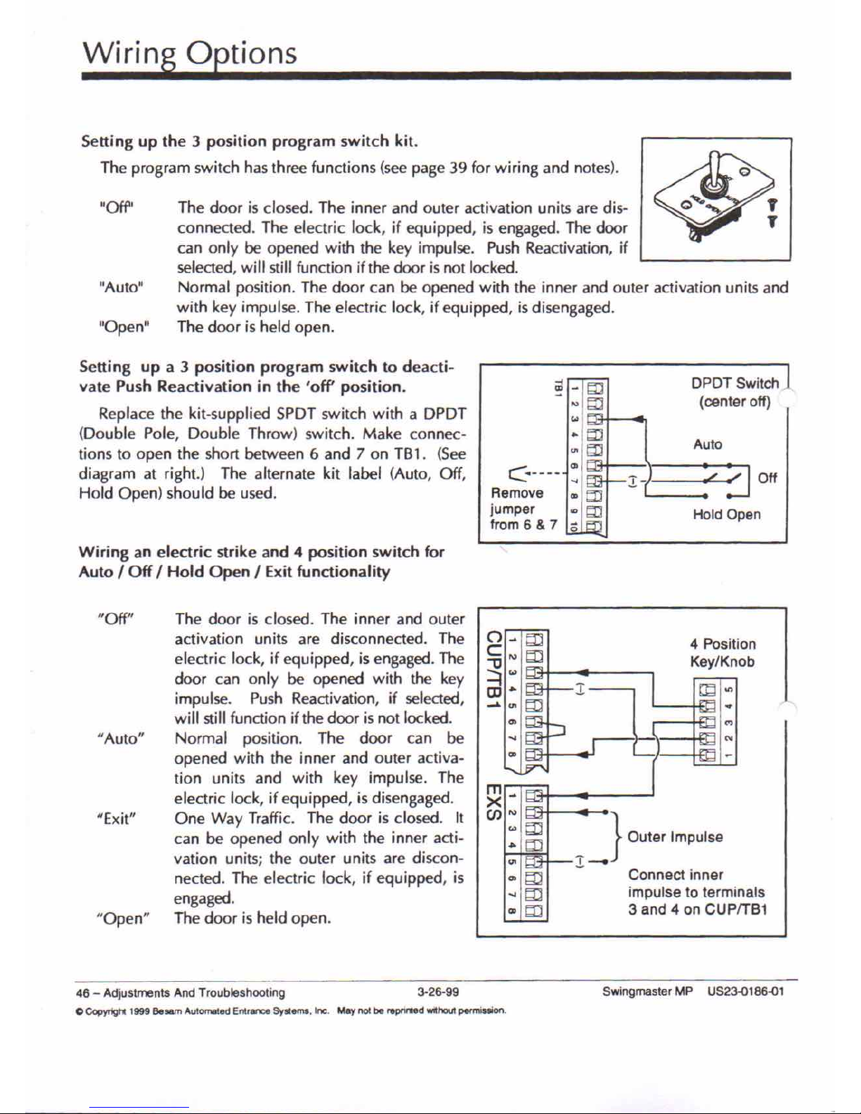
Sening up the 3 position program switch kit.
The program switch has three functions (see page 39 for wiring and notes).
"Ofr'
lIAuto"
"Open"
The door is closed. The inner and outer activation units are dis-
connected. The electric lock, if equipped, is engaged. The door
can only be opened with the key impulse. Push Reactivation, if
selected, will still function if the door is not locked.
Normal position. The door can be opened with the inner and outer activation units and
with key impulse. The electric lock, if equipped, is disengaged.
The door is held open.
Sening up a 3 position program switch to deacti-
vate Push Reactivation in the 'off position.
Replace the kit-supplied SPDT switch with a DPDT
(Double Pole, Double Throw) switch. Make connec-
tions to open the short between 6 and 7 on TB1. (See
diagram at right.) The alternate kit label (Auto, Off,
Hold Open) should be used.
Wiring an electric strike and 4 position switch for
AutoIOffIHold OpenIExit functionality
~-b::1
DPDTSwitch,
"'b::1
(center off)
•••
"bD
Auto
~1::l:I
C.----
00
...
1-
,;"w"
Off
Remove
oobD
jumper
~m
HoldOpen
Irom6&7
;;
"
_ } Outer Impulse
.1.-
Connect inner
impulse to terminals
3 and 4 on CUPITB1
"Off"
#Auto"
"Exit"
"Open"
The door is closed. The inner and outer
activation units are disconnected. The
electric lock, if equipped, is engaged. The
door can only be opened with the key
impulse. Push Reactivation, if selected,
will still function if the door is not locked.
Normal position. The door can be
opened with the inner and outer activa-
tion units and with key impulse. The
electric lock, if equipped, is disengaged.
One Way Traffic. The door is closed. It
can be opened only with the inner acti-
vation units; the outer units are discon-
nected. The electric lock, if equipped, is
engaged.
The door is held open.
~-
en'"
...m
.•.m
'"
4 Position
Key/Knob
1Jd'"
N
46 - Adjustments And Troubleshooting 3-26-99
o Copyngtt 1999 Besam Automated Enl.nn::e System., Inc. May not be repnnled wdhout permission.
Swingmaster MP US2300186001
Page 5
Wiring
0p.t.io.n.s _
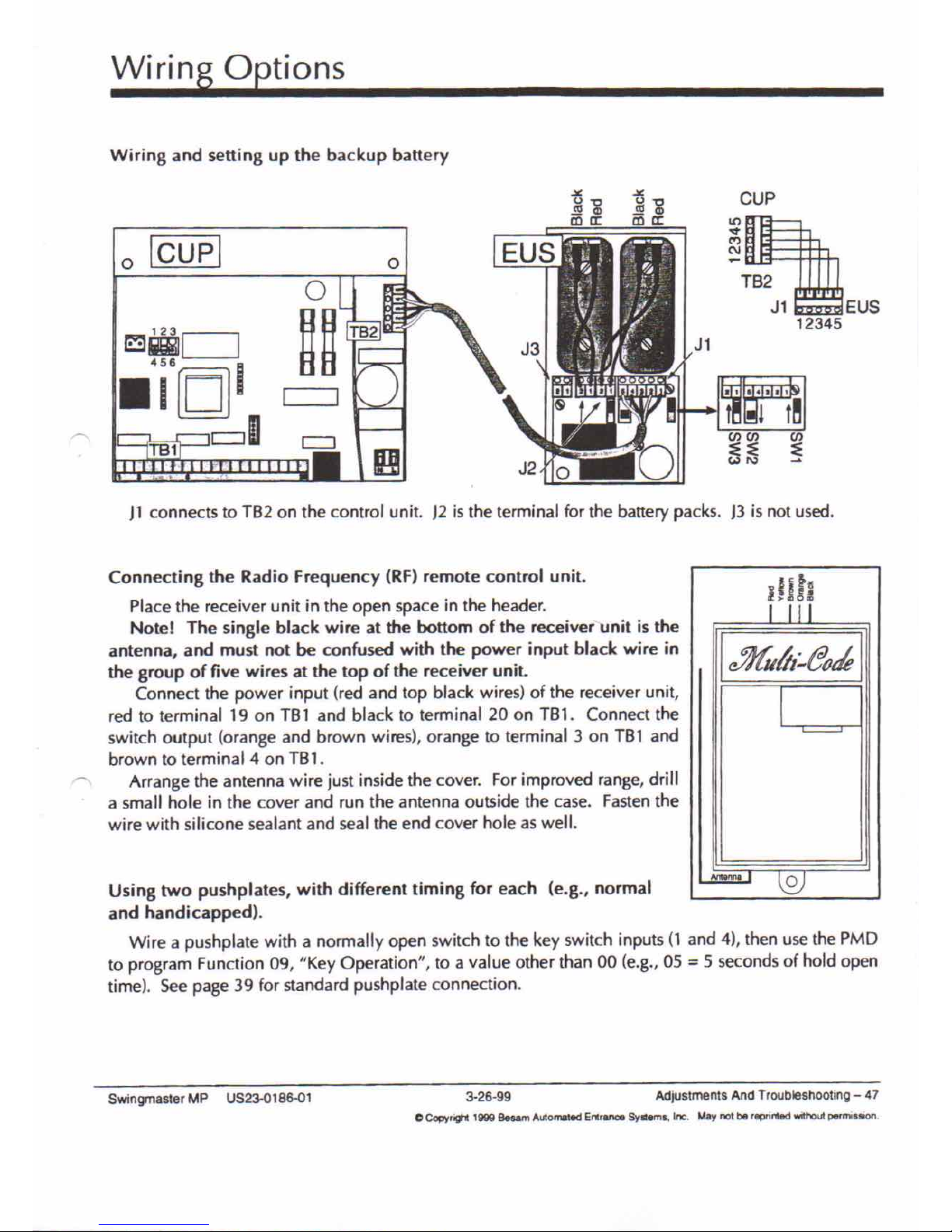
Wiring and setting up the backup battery
o
Icupl
CUP
TB2
Jl EUS
12345
)1 connects to TB2 on the control unit. )2 is the terminal for the battery packs. )3 is not used.
r~~
f'fff
I
c»fuUr:.eo~
I
I
AnO,.""
l2J
Using two pushplates, with different timing for each (e.g., normal
and handicapped).
Wire a pushplate with a normally open switch to the key switch inputs (l and 4), then use the PMD
to program Function 09, "Key Operation", to a value other than 00 (e.g., 05=5 seconds of hold open
time). See page 39 for standard pushplate connection.
Connecting the Radio Frequency (RF) remote control unit.
Place the receiver unit in the open space in the header.
Note I The single black wire at the bottom of the receiver-unit is the
antenna, and must not be confused with the power input black wire in
the group of five wires at the top of the receiver unit.
Connect the power input (red and top black wires) of the receiver unit,
red to terminal 19 on TB1 and black to terminal 20 on TBl. Connect the
switch output (orange and brown wires), orange to terminal 3 on TBI and
brown to terminal 4 on TB1.
'" Arrange the antenna wire just inside the cover. For improved range, drill
a small hole in the cover and run the antenna outside the case. Fasten the
wire with silicone sealant and seal the end cover hole as well.
Swingmaster MP US23-0186-01
3-26-99
Adjustments And Troobleshooting - 47
C Copyr9't
1999
Besam
Automated
Enlrance Syslems.
Ire.
May not be reprirted
WIthout
pet'mission
Page 6
Wiring Options - EXS Expansion Module
o
o
o
o
•
o
•
Caution: Use
groundingstrap
when installing
EXS .
.•••• r'
. n_1
f~J •
~
D_
o
o
:.0
• c:l
o
lcupl
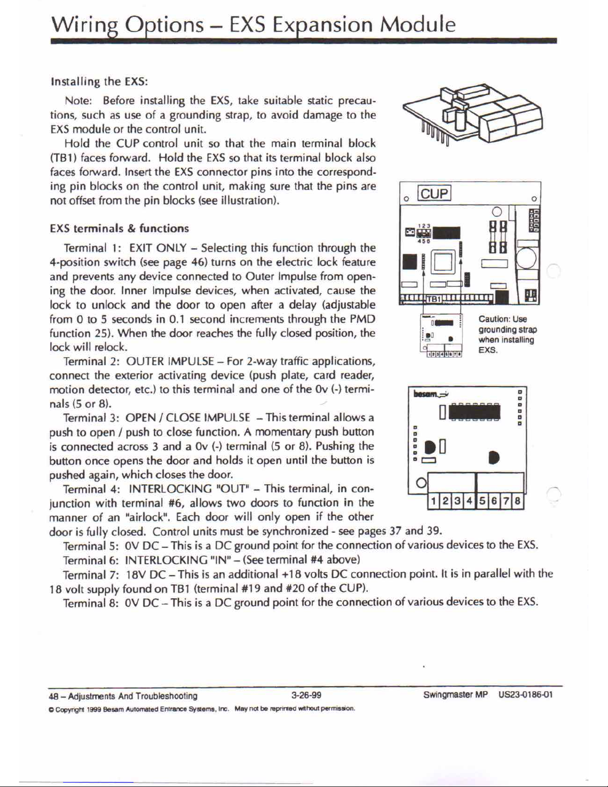
Installing the EXS:
Note: Before installing the EXS, take suitable static precau-
tions. such as use of a grounding strap, to avoid damage to the
EXSmodule or the control unit.
Hold the CUP control unit so that the main terminal block
(TB1) faces forward. Hold the EXSso that its terminal block also
faces forward. Insert the EXSconnector pins into the correspond-
ing pin blocks on the control unit, making sure that the pins are
not offset from the pin blocks (see illustration).
EXS terminals
&
functions
Terminal 1: EXIT ONLY - Selecting this function through the
4-position switch (see page 46) turns on the electric lock feature
and prevents any device connected to Outer Impulse from open.
ing the door. Inner Impulse devices, when activated, cause the
lock to unlock and the door to open after a delay (adjustable
from 0 to 5 seconds in 0.1 second increments through the PMD
function 25). When the door reaches the fully closed position, the
lock will relock.
Terminal 2: OUTER IMPULSE - For 2-way traffic applications,
connect the exterior activating device (push plate, card reader,
motion detector, etc.) to this terminal and one of the Ov (.) termi-
nals (5 or 8). -'
Terminal 3: OPENICLOSE IMPULSE - This terminal allows a
push to openIpush to close function. A momentary push button
is connected across 3 and a Ov (-) terminal (5 or 8). Pushing the
button once opens the door and holds it open until the button is
pushed again, which closes the door.
Terminal 4: INTERLOCKING "OUT" - This terminal, in con-
junction with terminal #6, allows two doors to function in the
manner of an "airlock". Each door will only open if the other
door is fully closed. Control units must be synchronized. see pages 37 and 39.
Terminal 5: OV DC - This is a DC ground point for the connection of various devices to the EXS.
Terminal 6: INTERLOCKING "IN" - (Seeterminal #4 above)
Terminal 7: 18V DC - This is an additional +18 volts DC connection point. It is in parallel with the
18 volt supply found on TB 1 (terminal #19 and #20 of the CUP).
Terminal 8: OV DC - This is a DC ground point for the connection of various devices to the EXS.
48 - Adjustments And Troubleshooting 3.26-99
c
Copyrigtt 1999 Beaam Automated
Entrance
Systems. Inc. May nOl:be ntpnrted WiU"loutpermi•• on.
SwingmasterMP US23.Q186.Ql
Page 7
50 - AdjustmentsAndTroubleshooting
o
Copyrig1
1999
Besam Automated Entrance
Systems. Inc.
'!
Y
be reprinted
witt'out permission.
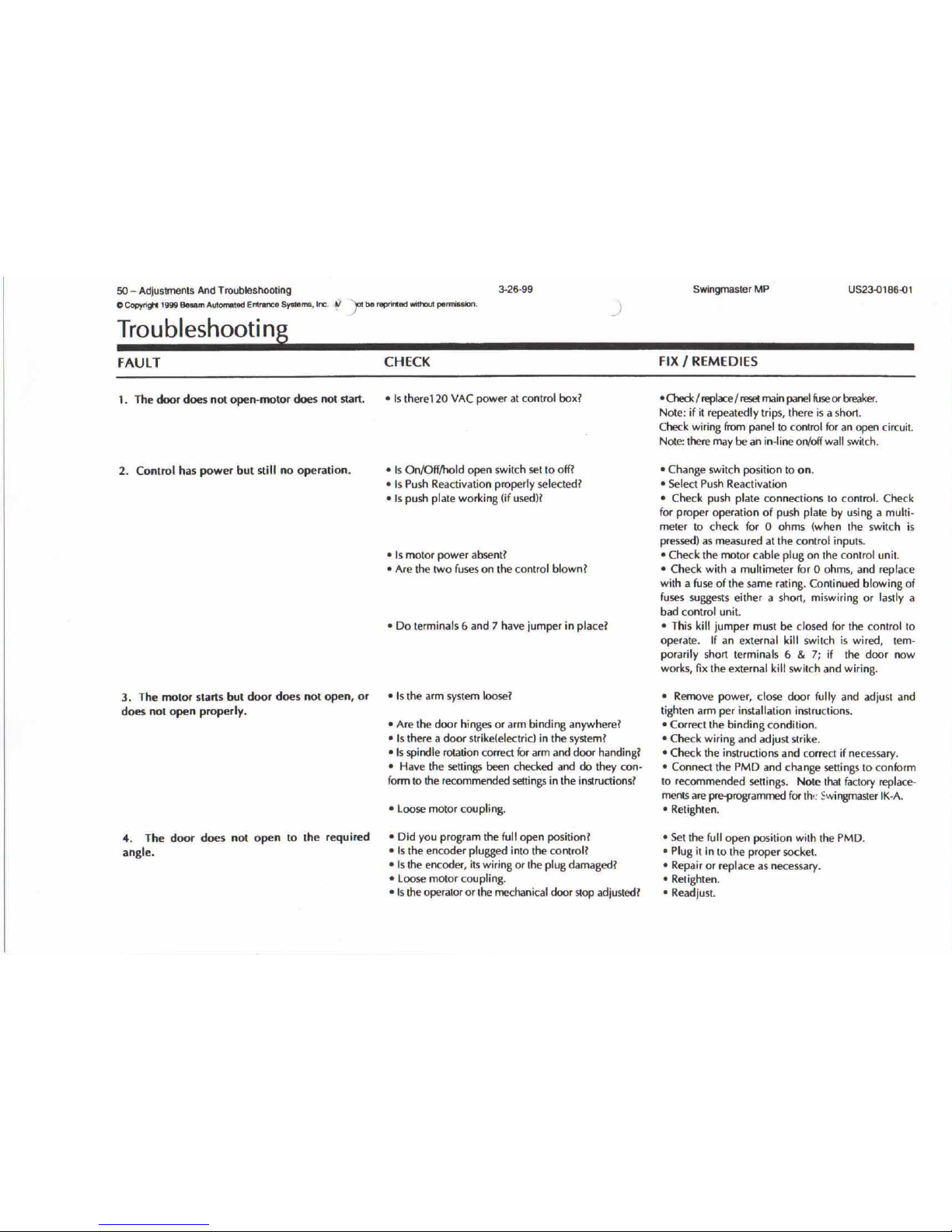
Trou bleshooti ng
3-26-99
)
SwingmaslerMP
US23-o186-ot
FAULT
1_ The door does nol open-motor does not start.
2. Control has power but still no operation.
3. The motor starts but door does not open, or
does not open properly.
4. The door does not open 10 Ihe required
angle.
CHECK
• Is there120 VAC power al control box?
• Is On/Offlhold open switch set to off?
• Is Push Reactivation properly selected?
• Is push plate working (if used)?
• Is motor power absent?
• Are the two fuses on the control blown?
• Do terminals 6 and 7 have jumper in place?
• Is the arm system loose?
• Are the door hinges or arm binding anywherel
• Is there a door strikelelectricl in the system!
• Is spindle rotation correct br arm and door handing?
• Have the settings been checked and do they con-
fonmto the recommended settings in the instructions?
• loose motor coupling.
• Did you program the full open position?
• Is the encoder plugged into the controll
• Is the encoder, its wiring or the plug damaged?
• loose motor coupling.
• Is the operator or the mechanical door stop adjusted?
FIXIREMEDIES
• CheckIreplaceIresetmain panel fuseor breaker.
Note: if il repeatedly trips, there is a short.
Check wiring from panel to conlrol for an open circuit.
Note: lhere may be an in-line on/offwall switch.
• Change swilch position to on.
• Select Push Reactivation
• Check push plate connections to control. Check
for proper operation of push plale by using a multi-
meier to check for 0 ohms (when the switch is
pressed) as measured at the control inputs .
• Check the motor cable plug on the control unit.
• Check wilh a multimeter for 0 ohms, and replace
with a fuse of the same rating. Conlinued blowing of
fuses suggests either a short, miswiring or lastly a
bad control unit.
• This kill jumper musl be closed for the control to
operate. If an external kill swilch is wired, tem-
porarily short terminals 6 & 7; if the door now
works, fix the external kill swilch and wiring .
• Remove power, close door fully and adjust and
tighten anm per installation inslruclions.
• Correct the binding condition .
• Check wiring and adjust slrike.
• Check the instructions and correct if necessary.
• Connect the PMD and change settings to conform
to recommended settings. NOle that factory replace-
ments are pr"1'rogrammed for th,: SwingmasterIK-A.
• Retighten.
• Set the full open position with the PMD.
• Plug il in to the proper socket.
• Repair or replace as necessary .
• Relighten.
• Readjust.
Page 8
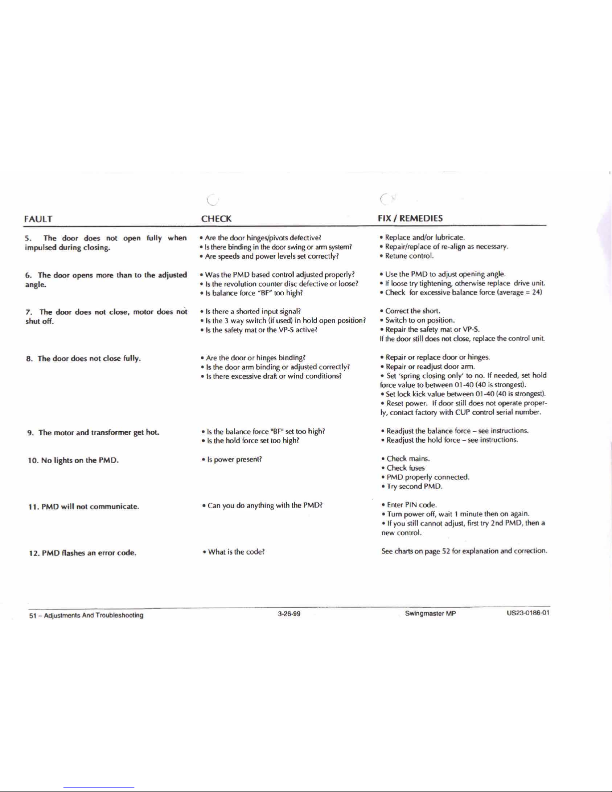
FAULT
5. The door does not open fully when
impulsed during closing.
6. The door opens more than to the adjusted
angle.
7. The door does not close, motor does not
shut off.
8. The door does not close fully.
9. The motor and transformer get hot.
10. No lights on the PMD.
11. PMD will not communicate.
12. PMD flashes an error code.
C'
CHECK
o Are the door hinges/pivots defectivel
ols there binding in the door swing or arm systeml
o Are speeds and power levels set correctly I
o Was the PMD based control adjusted properlyl
o Is the revolution counter disc defective or loosel
o Is balance force "BF" too highl
o Is there a shorted input signall
o Is the 3 way switch (if used) in hold open positionl
o Is the safety mat or the VP-S activel
o Are the door or hinges bindingl
o Is the door arm binding or adjusted correctlyl
o Is there excessive draft or wind conditionsl
o Is the balance force 'BF' set too highl
o Is the hold force set too highl
o Is power presentl
o Can you do anything with the PMDI
o What is the codel
(,
FIXIREMEDIES
o Replace and/or lubricate.
o Repair/replace of re-align as necessary.
o Retune control.
o Use the PMD to adjust opening angle.
o If loose try tightening. otherwise replace drive unit.
o Check for excessive balance force (average=24)
o Correct the short.
o Switch to on position.
o Repair the safety mat or VP-S.
Ifthe door still does not close, replace the control unit.
o Repair or replace door or hinges.
o Repair or readjust door arm.
o Set 'spring closing only' to no. If needed, set hold
force value to between 01-40 (40 is strongest).
o Set lock kick value between 01-40 (40 is strongest).
o Reset power. Ifdoor still does not operate proper.
Iy, contact factory with CUP control serial number.
o Readjust the balance force - see instructions.
o Readjust the hold force - see instructions.
o Check mains.
o Check fuses
o PMD properly connected.
o Try second PMD.
o Enter PIN code.
o Turn power off, wait 1 minute then on again.
o If you still cannot adjust, first try 2nd PMD, then a
new control.
See charts on page 52 for explanation and correction.
51 - AdjustmentsAndTroubleshooting
3-26-99
Swingmaster MP
US23.Q186.Ql
Page 9
52 - Adjustments And Troubleshooting
OCopyri~
1999 eeum Automaled Enlr811Ce5ysteme,
Inc.
May not be reprinled wilhoot petrTieaion.
3-26-99
Swingmaster MP
US23.o186.o1
PMD Codes, Tests and Status
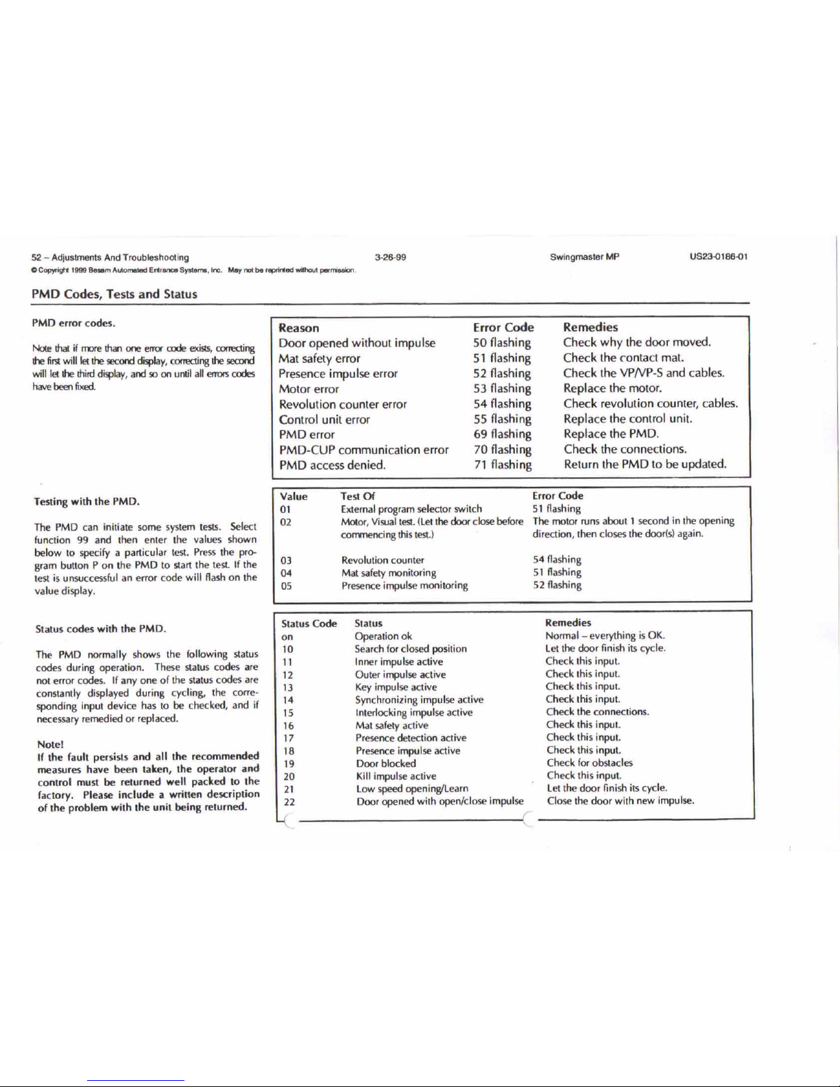
PMD error codes.
Note !hat if me than one error rode exisrs, rorrecting
!he fir.;!will let !he second display, rorrecting !he second
will let !he Ihird display, and so on until all errors codes
have been fixed.
Reason
Door opened without impulse
Mat safety error
Presence impulse error
Motor error
Revolution counter error
Control unit error
PMD error
PMD-CUP communication error
PMD accessdenied.
Error Code
50 flashing
51 flashing
52 flashing
53 flashing
54 flashing
55 flashing
69 flashing
70 flashing
71 flashing
Remedies
Check why the door moved.
Check the contact mat.
Check the VPNP-S and cables.
Replace the motor.
Check revolution counter, cables.
Replace the control unit.
Replace the PMD.
Check the connections.
Return the PMD to be updated.
Testing with the PMD.
The PMD can initiate some system tests. Select
function 99 and lhen enler the values shown
below to specify a particular test. Press the pro-
gram button P on the PMD to start the test. If the
lest is unsuccessful an error code will flash on the
value display.
Value
01
02
03
04
05
Test Of
External program selector switch
Molor, Visual test. (leI the door close before
commencing this test.)
Revolution counter
Mat safety monitoring
Presence impulse monitoring
Error Code
51 flashing
The motor nuns about 1 second in lhe opening
direction, then closes the door!s) again.
54 flashing
51 flashing
52 flashing
Remedies
Normal- everything is OK.
let the door finish its cycle.
Check this input.
Check this input.
Check this input.
Check lhis input.
Check the conneclions.
Check this input.
Check this input.
Check lhis input.
Check for obstacles
Check this input.
let the door finish its cycle.
Close the door with new impulse.
Status
Operation ok
Search for closed position
Inner impulse active
Outer impulse active
Key impulse active
Synchronizing impulse aclive
Interlocking impulse active
Mat safely aclive
Presence detection aclive
Presence impulse active
Door blocked
Kill impulse active
low speed opening/learn
Door opened with open/close impulse
--------(
Status Code
on
10
11
12
13
14
15
16
17
18
19
20
21
22
The PMD normally shows the following status
codes during operation. These status codes are
not error codes. If anyone of the status codes are
constantly displayed during cycling, the corre-
sponding inpul device has10be checked, and if
necessary remedied or replaced.
Notel
If the fault persists and all the recommended
measures have been taken, the operator and
control must be returned well packed to the
factory. Please include a written description
of the problem with the unit being returned.
Status codes with the PMD.
Page 10
Door/Operator Handing
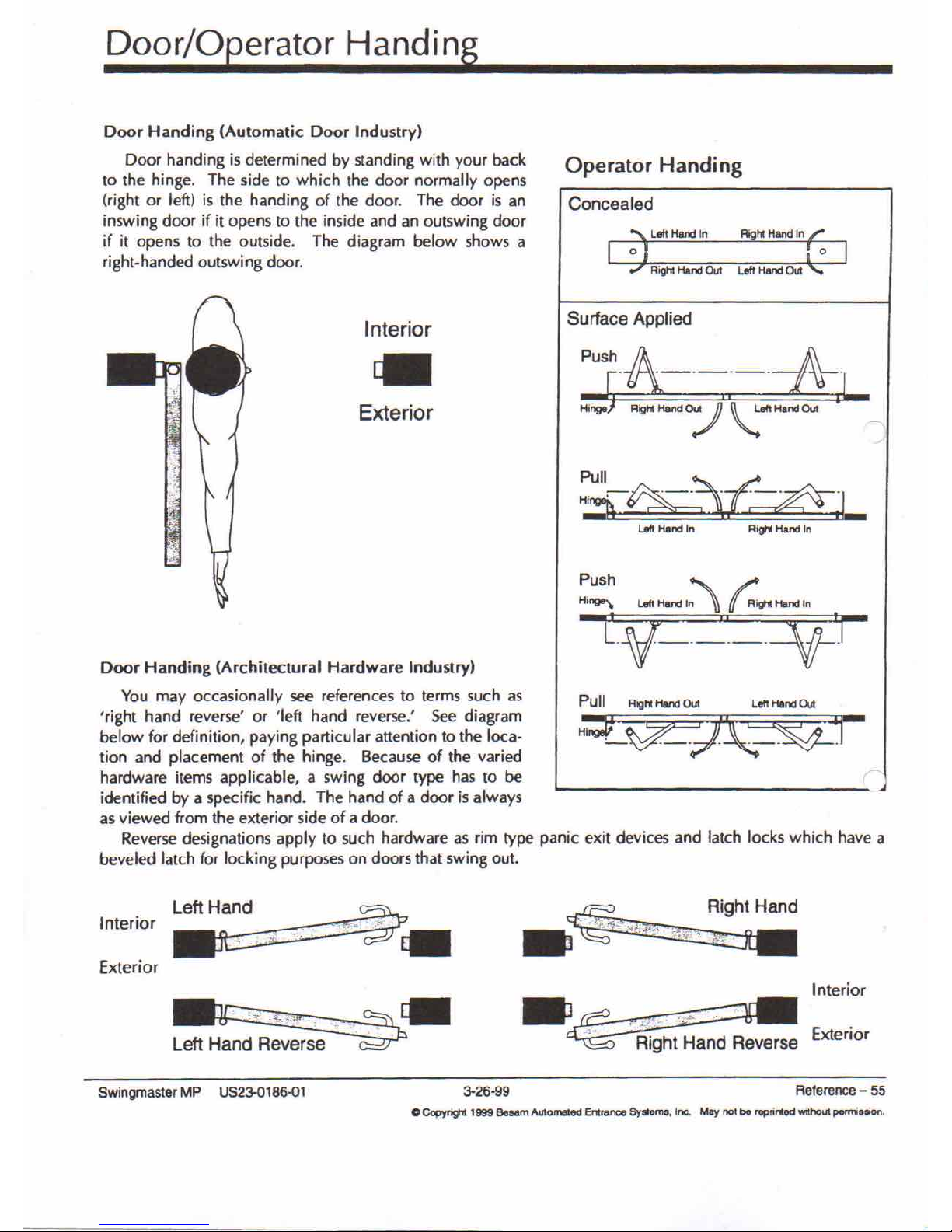
Door Handing (Automatic Door Industry)
Door handing is determined by standing with your back
to the hinge. The side to which the door normally opens
(right or left) is the handi ng of the door. The door is an
inswing door if it opens to the inside and an outswing door
if it opens to the outside. The diagram below shows a
right-handed outswing door.
Operator Handing
Concealed
LeftHandIn RighiHandIn
Righi Hand Out Left Hand Out
o
Interior
Exterior
Surface Applied
lett Hand In
Ri'" Hand In
r
lell Hand Out
Push ~ ~
Hi~ left HandIn \}
(f
RVt Hanel
In
L_V-__"-
=\j'_r
Pull R;g" Hand Out
H~~J/~r
Door Handing (Architectural Hardware Industry)
You may occasionally see references to terms such as
'right hand reverse' or 'left hand reverse.' See diagram
below for definition, paying particular attention to the loca-
tion and placement of the hinge. Because of the varied
hardware items applicable, a swing door type has to be
identified by a specific hand. The hand of a door is always
as viewed from the exterior side of a door.
Reverse designations apply to such hardware as rim type panic exit devices and latch locks which have a
beveled latch for locking purposes on doors that swing out.
Left Hand
Interior
;{Z,_ .
Rig.ht Hand
_ . .i.J"',' ~
,.,,.;.i', _',"''':..'
Exterior
Interior
Left Hand Reverse
-~' :::- -2
j
'::;:'-"-:':;. ;:::::::~
~ Exterior
Right Hand Reverse
Swingmaster MP US23-0186-Q1
3-26-99
Reference - 55
C Copyf91l 1999 Besam Al1tomaled Entrance
51.ems,
Inc. May not be
reprir1.ed
without permilllion.
 Loading...