

Page 1
An ASSA ABLOY Group company
1003090-EI-2.0 – Issue 2006-12-21
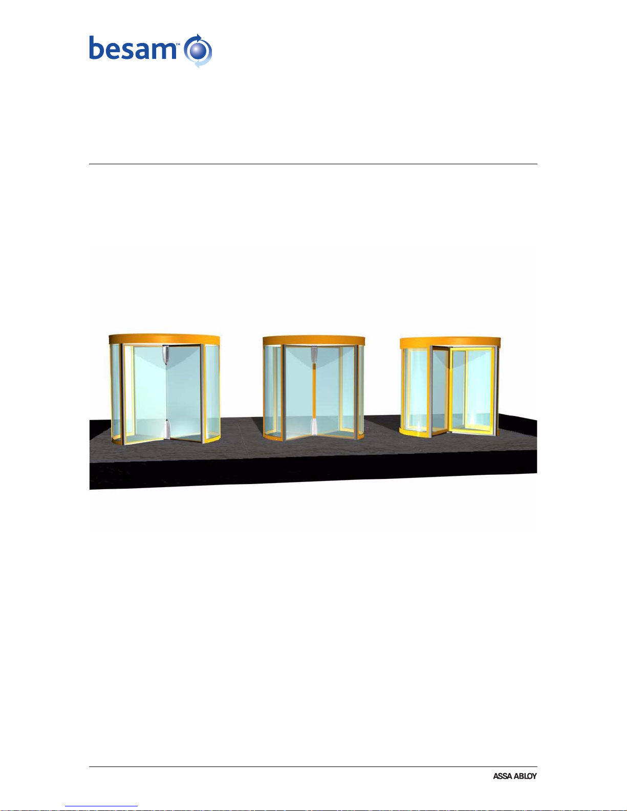
Besam Revolving Door RD3/RD4
User Manual
Page 2

2 Issue 2006-12-21 1003090-EI-2.0
© All rights in and to this material are the sole property of ASSA ABLOY Entrance Systems AB. Copying, scanning,
alterations or modifications are expressly forbidden without the prior written consent of applicable company within
ASSA ABLOY Entrance Systems AB. Rights reserved for changes without prior notice.
Page 3

1003090-EI-2.0 Issue 2006-12-21 3
1. Important information . . . . . . . . . . . . . . . . . . . . . . . . . . . . . . . . . . . . . . . . . . . . . . . . . . .5
1.1 Important safety instructions for use . . . . . . . . . . . . . . . . . . . . . . . . . . . . . . . . . . . . . 5
1.2 Environment . . . . . . . . . . . . . . . . . . . . . . . . . . . . . . . . . . . . . . . . . . . . . . . . . . . . . . . 5
2. Introduction . . . . . . . . . . . . . . . . . . . . . . . . . . . . . . . . . . . . . . . . . . . . . . . . . . . . . . . . . .5
3. Service . . . . . . . . . . . . . . . . . . . . . . . . . . . . . . . . . . . . . . . . . . . . . . . . . . . . . . . . . . . . . . 6
4. Main parts . . . . . . . . . . . . . . . . . . . . . . . . . . . . . . . . . . . . . . . . . . . . . . . . . . . . . . . . . . .7
5. Operation . . . . . . . . . . . . . . . . . . . . . . . . . . . . . . . . . . . . . . . . . . . . . . . . . . . . . . . . . . . .8
5.1 Programme selector . . . . . . . . . . . . . . . . . . . . . . . . . . . . . . . . . . . . . . . . . . . . . . . . .8
5.2 Start up . . . . . . . . . . . . . . . . . . . . . . . . . . . . . . . . . . . . . . . . . . . . . . . . . . . . . . . . . . .8
5.3 Switch off . . . . . . . . . . . . . . . . . . . . . . . . . . . . . . . . . . . . . . . . . . . . . . . . . . . . . . . . .9
5.4 Reset . . . . . . . . . . . . . . . . . . . . . . . . . . . . . . . . . . . . . . . . . . . . . . . . . . . . . . . . . . . . .9
6. Safety equipment . . . . . . . . . . . . . . . . . . . . . . . . . . . . . . . . . . . . . . . . . . . . . . . . . . . . .10
6.1 Standard . . . . . . . . . . . . . . . . . . . . . . . . . . . . . . . . . . . . . . . . . . . . . . . . . . . . . . . . . 11
6.1.1 Compressible safety switches. . . . . . . . . . . . . . . . . . . . . . . . . . . . . . . . . . . . . . . 11
6.1.2 Force sensitive door leaves . . . . . . . . . . . . . . . . . . . . . . . . . . . . . . . . . . . . . . . . 11
6.1.3 Emergency stop push-button . . . . . . . . . . . . . . . . . . . . . . . . . . . . . . . . . . . . . . . 12
7. Programme selector PCD . . . . . . . . . . . . . . . . . . . . . . . . . . . . . . . . . . . . . . . . . . . . . .13
7.1 General information . . . . . . . . . . . . . . . . . . . . . . . . . . . . . . . . . . . . . . . . . . . . . . . . . 13
7.2 Access code . . . . . . . . . . . . . . . . . . . . . . . . . . . . . . . . . . . . . . . . . . . . . . . . . . . . . . 14
7.2.1 Login to the PCD. . . . . . . . . . . . . . . . . . . . . . . . . . . . . . . . . . . . . . . . . . . . . . . . .14
7.2.2 Logout from the PCD . . . . . . . . . . . . . . . . . . . . . . . . . . . . . . . . . . . . . . . . . . . . .14
7.2.3 Change access code . . . . . . . . . . . . . . . . . . . . . . . . . . . . . . . . . . . . . . . . . . . . . 14
7.2.4 The ON/OFF switch . . . . . . . . . . . . . . . . . . . . . . . . . . . . . . . . . . . . . . . . . . . . . .15
7.3 Changing operating mode . . . . . . . . . . . . . . . . . . . . . . . . . . . . . . . . . . . . . . . . . . . .15
7.3.1 The different operating modes . . . . . . . . . . . . . . . . . . . . . . . . . . . . . . . . . . . . . . 16
7.4 Real time operation . . . . . . . . . . . . . . . . . . . . . . . . . . . . . . . . . . . . . . . . . . . . . . . . . 17
7.4.1 Activation . . . . . . . . . . . . . . . . . . . . . . . . . . . . . . . . . . . . . . . . . . . . . . . . . . . . . . 17
7.4.2 Deactivation . . . . . . . . . . . . . . . . . . . . . . . . . . . . . . . . . . . . . . . . . . . . . . . . . . . . 17
7.4.3 ON/OFF . . . . . . . . . . . . . . . . . . . . . . . . . . . . . . . . . . . . . . . . . . . . . . . . . . . . . . . 18
7.4.4 Manually setting of operation mode . . . . . . . . . . . . . . . . . . . . . . . . . . . . . . . . . . 18
7.4.5 Summertime/Wintertime . . . . . . . . . . . . . . . . . . . . . . . . . . . . . . . . . . . . . . . . . . . 18
7.5 Read speed settings . . . . . . . . . . . . . . . . . . . . . . . . . . . . . . . . . . . . . . . . . . . . . . . . 19
7.6 Real time clock . . . . . . . . . . . . . . . . . . . . . . . . . . . . . . . . . . . . . . . . . . . . . . . . . . . .19
7.6.1 Read real time clock . . . . . . . . . . . . . . . . . . . . . . . . . . . . . . . . . . . . . . . . . . . . . . 19
7.7 Remote Control Operation. . . . . . . . . . . . . . . . . . . . . . . . . . . . . . . . . . . . . . . . . . . . 20
7.7.1 Communication ON/OFF . . . . . . . . . . . . . . . . . . . . . . . . . . . . . . . . . . . . . . . . . . 21
7.7.2 Login . . . . . . . . . . . . . . . . . . . . . . . . . . . . . . . . . . . . . . . . . . . . . . . . . . . . . . . . . . 21
7.7.3 Logout . . . . . . . . . . . . . . . . . . . . . . . . . . . . . . . . . . . . . . . . . . . . . . . . . . . . . . . . . 21
7.8 Main menu. . . . . . . . . . . . . . . . . . . . . . . . . . . . . . . . . . . . . . . . . . . . . . . . . . . . . . . .21
7.9 Door operation. . . . . . . . . . . . . . . . . . . . . . . . . . . . . . . . . . . . . . . . . . . . . . . . . . . . .22
7.9.1 Other information on screen (EI). . . . . . . . . . . . . . . . . . . . . . . . . . . . . . . . . . . . . 22
8. Maintenance. . . . . . . . . . . . . . . . . . . . . . . . . . . . . . . . . . . . . . . . . . . . . . . . . . . . . . . . . 23
Table of content
Page 4

4 Issue 2006-12-21 1003090-EI-2.0
9. Options. . . . . . . . . . . . . . . . . . . . . . . . . . . . . . . . . . . . . . . . . . . . . . . . . . . . . . . . . . . . . 24
9.1 Compressible safety switches on the door leaves. . . . . . . . . . . . . . . . . . . . . . . . . . 24
9.2 Infrared presence sensor. . . . . . . . . . . . . . . . . . . . . . . . . . . . . . . . . . . . . . . . . . . . . 24
9.3 Vertical presence photocell sensor PDR . . . . . . . . . . . . . . . . . . . . . . . . . . . . . . . . . 25
9.4 Break-out kit . . . . . . . . . . . . . . . . . . . . . . . . . . . . . . . . . . . . . . . . . . . . . . . . . . . . . . 25
9.5 Emergency opening push-button. . . . . . . . . . . . . . . . . . . . . . . . . . . . . . . . . . . . . . . 25
9.6 Push-button for disabled . . . . . . . . . . . . . . . . . . . . . . . . . . . . . . . . . . . . . . . . . . . . . 26
9.7 Push-button inside door. . . . . . . . . . . . . . . . . . . . . . . . . . . . . . . . . . . . . . . . . . . . . . 26
10. Accessories . . . . . . . . . . . . . . . . . . . . . . . . . . . . . . . . . . . . . . . . . . . . . . . . . . . . . . . . .27
10.1 Rotation brake (lock) . . . . . . . . . . . . . . . . . . . . . . . . . . . . . . . . . . . . . . . . . . . . . . . . 27
10.2 Electromechanical lock . . . . . . . . . . . . . . . . . . . . . . . . . . . . . . . . . . . . . . . . . . . . . . 27
10.3 Direction sensing radar DSR . . . . . . . . . . . . . . . . . . . . . . . . . . . . . . . . . . . . . . . . . . 28
10.4 Night closing door NCD . . . . . . . . . . . . . . . . . . . . . . . . . . . . . . . . . . . . . . . . . . . . . . 28
10.5 Modem. . . . . . . . . . . . . . . . . . . . . . . . . . . . . . . . . . . . . . . . . . . . . . . . . . . . . . . . . . . 28
11. Troubleshooting . . . . . . . . . . . . . . . . . . . . . . . . . . . . . . . . . . . . . . . . . . . . . . . . . . . . . . 29
11.1 Supervision system . . . . . . . . . . . . . . . . . . . . . . . . . . . . . . . . . . . . . . . . . . . . . . . . . 29
11.2 Simple troubleshooting . . . . . . . . . . . . . . . . . . . . . . . . . . . . . . . . . . . . . . . . . . . . . . 29
11.2.1 The door does not start at start up . . . . . . . . . . . . . . . . . . . . . . . . . . . . . . . . . . . 29
11.2.2 Service request . . . . . . . . . . . . . . . . . . . . . . . . . . . . . . . . . . . . . . . . . . . . . . . . . . 29
11.3 Code list. . . . . . . . . . . . . . . . . . . . . . . . . . . . . . . . . . . . . . . . . . . . . . . . . . . . . . . . . .30
11.4 Status codes . . . . . . . . . . . . . . . . . . . . . . . . . . . . . . . . . . . . . . . . . . . . . . . . . . . . . .31
11.4.1 Diagnostic out-put . . . . . . . . . . . . . . . . . . . . . . . . . . . . . . . . . . . . . . . . . . . . . . . . 31
11.4.2 Control unit CDC. . . . . . . . . . . . . . . . . . . . . . . . . . . . . . . . . . . . . . . . . . . . . . . . .31
12. Mark up table . . . . . . . . . . . . . . . . . . . . . . . . . . . . . . . . . . . . . . . . . . . . . . . . . . . . . . . .32
12.1 Floor levelling information from installation . . . . . . . . . . . . . . . . . . . . . . . . . . . . . . . 32
12.1.1 Floor surface levelling values . . . . . . . . . . . . . . . . . . . . . . . . . . . . . . . . . . . . . . . 32
13. Revolving door log book. . . . . . . . . . . . . . . . . . . . . . . . . . . . . . . . . . . . . . . . . . . . . . . . 33
14. Real time operation . . . . . . . . . . . . . . . . . . . . . . . . . . . . . . . . . . . . . . . . . . . . . . . . . . . 34
Page 5

Important information
1003090-EI-2.0 Issued 2006-12-21 5
1.0
Important information
1.1
Important safety instructions for use
To avoid bodily injury, material damage and malfunction of the product, the
instructions contained in this manual must be followed. Save these instructions.
1.2
Environment
This operator may be equipped with batteries containing materials which are hazardous to the environment. Remove the batteries from the operator before it is
scrapped. The batteries must be disposed of safely.
2.0 Introduction
This manual contains necessary details and instructions for the daily use of the
Besam revolving door RD3/RD4.
Besam RD3/RD4 is designed to offer continuous use, a high degree of safety and
maximum lifetime. The system is self-adjusting to the effects caused by normal
variations in the weather conditions and to minor friction changes caused by e.g.
dirt.
Rights reserved for any changes without previous notice.
Page 6

Service
6 Issued 2006-12-21 1003090-EI-2.0
3.0 Service
When your door needs to be serviced, contact the nearest authorized Besam
service centre.
We recommend inspection of doors at least once a year (see page 23). According
to regulations inspection of emergency escape doors is required at least twice a
year, carried out by an authorized service centre. Please check the service book.
Place for telephone number, stamp, sticker or the like.
Page 7
Main parts
1003090-EI-2.0 Issued 2006-12-21 7
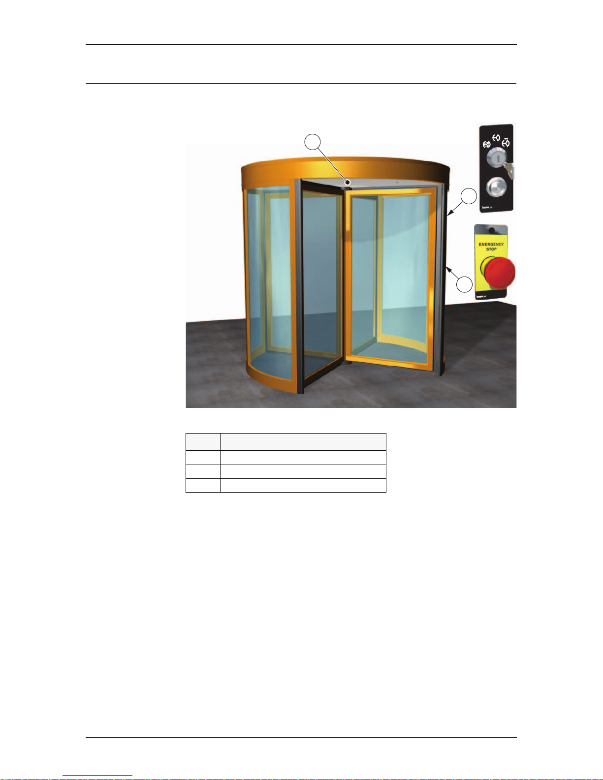
4.0 Main parts
No Description
1 Programme selector and reset push-button
2 Emergency stop push-button
3 Activation unit
1
3
2
Page 8
Operation
8 Issued 2006-12-21 1003090-EI-2.0
5.0 Operation
5.1 Programme selector
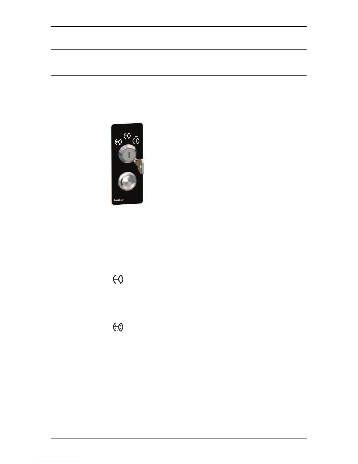
The programme selector is equipped with a three position key switch and a reset
push-button.
Note! If the door is equipped with a PCD programme selector, (see page 13).
5.2 Start up
• Open the night security doors, if fitted
• Unlock the mechanical lock, if fitted
• Check that the door emergency stop push-button is released. If not, turn the
button in any direction to release
Automatic operation
• Turn the programme selector to automatic operation
• The electro-mechanical lock, if fitted, is now unlocked
The door is parked at home position when there is no traffic. As soon as the activation units detect approaching traffic, the door automatically starts to rotate.
Continuous rotation
• Turn the programme selector to continuous rotation
• The electro-mechanical lock, if fitted, is unlocked
The door rotates continuously at a low speed. As soon as the activation units
detect approaching traffic, the door accelerates to normal speed. The door will
then return to low speed when there is no traffic.
Page 9
Operation
1003090-EI-2.0 Issued 2006-12-21 9
5.3 Switch off
• Check there is no traffic
• Turn the programme selector to off position
The door rotates to its home position
The electro-mechanical lock, if fitted, is locked
• Lock the mechanical lock, if fitted
• Close and lock the night security doors, if fitted
5.4 Reset
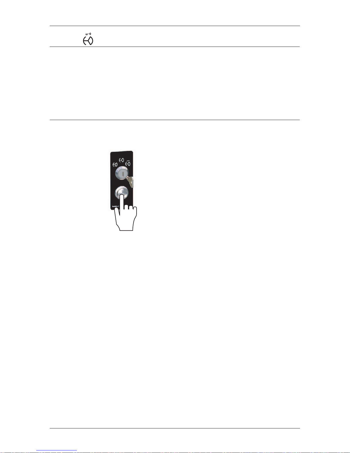
• In case of an error reset the door by pressing the reset push-button
Page 10
Safety equipment
10 Issued 2006-12-21 1003090-EI-2.0
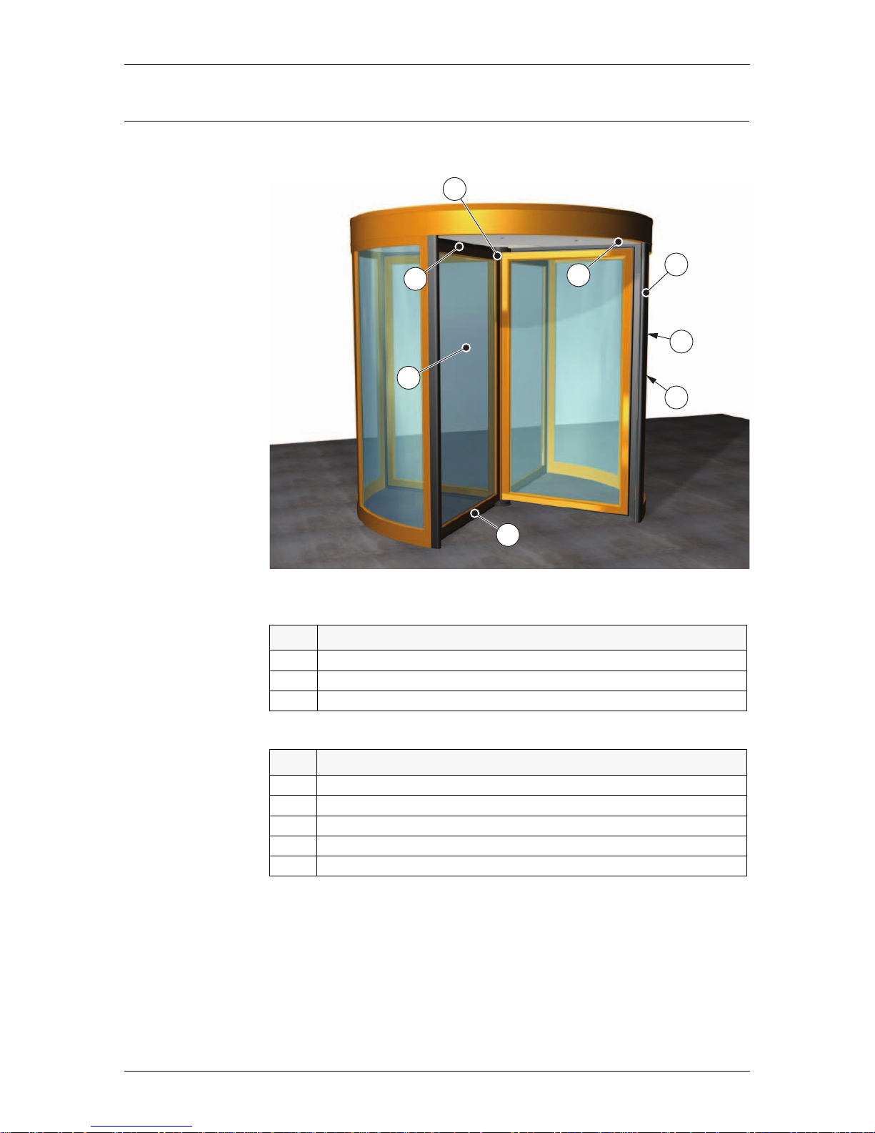
6.0 Safety equipment
Standard
Options
No Description
1 Compressible safety switches placed on the drum edges (see page 11)
2 Force sensitive door leaves (see page 11)
3 Emergency stop push-button (see page 12)
No Description
A Compressible safety switches placed on the door leaves (see page 24)
B Infrared presence sensing system (see page 24)
C Vertical presence photocell sensor PDR (see page 25)
D Break-out kit (see page 25)
E Push-button for disabled (see page 26)
ILL-00043
1
3
B
C
E
D
2
A
Page 11
Safety equipment
1003090-EI-2.0 Issued 2006-12-21 11
6.1 Standard
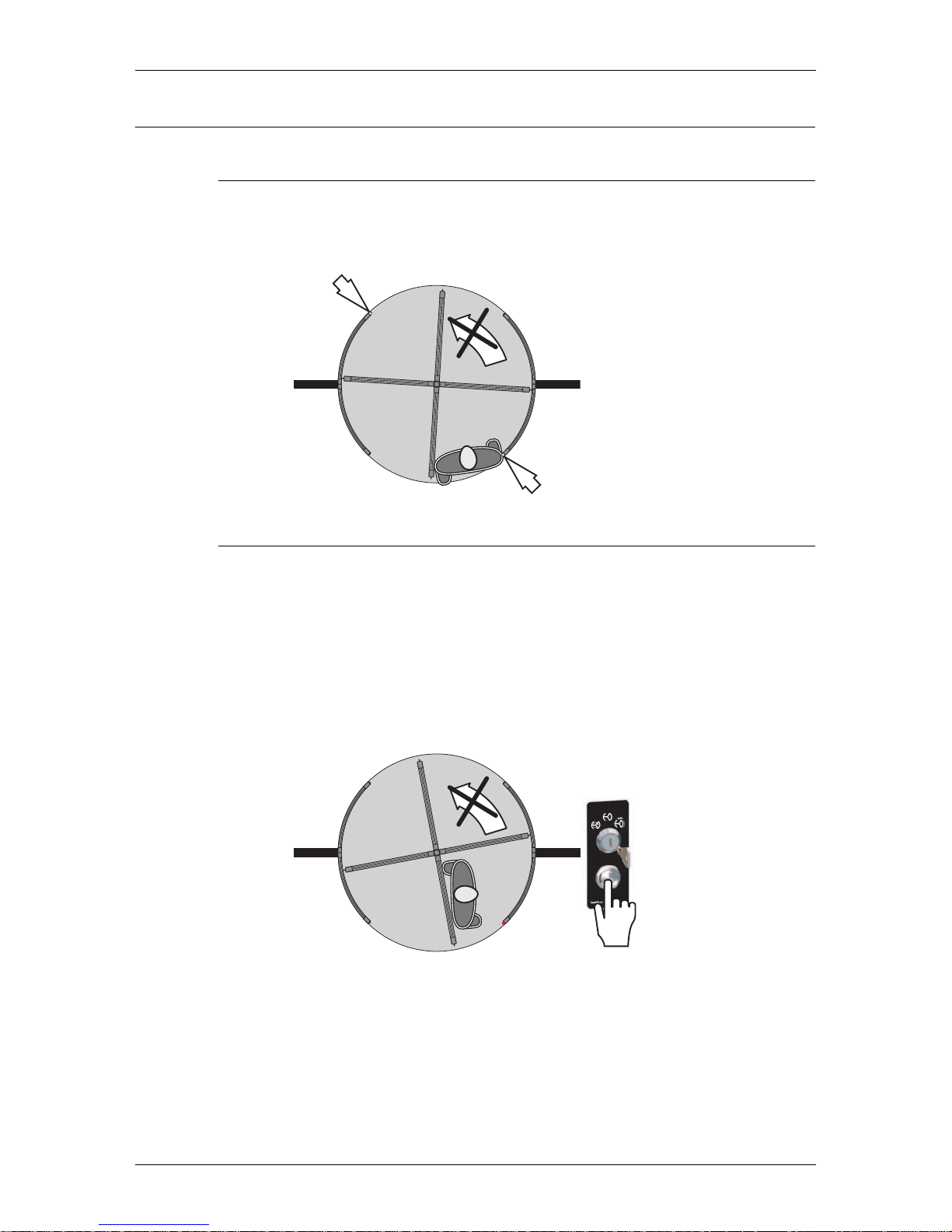
6.1.1 Compressible safety switches
Compressible safety switches on the drum edges. These stop the rotation if compressed. When the obstacle is removed, the rotation continues.
6.1.2 Force sensitive door leaves
• If the system detects an obstacle blocking the door, the power to the motor is
shut-off
• The door makes three attempts to start. After these three attempts the door
waits for a while and then makes one new attempt to start
• If the door is pushed out of position during this waiting period, the system is
reset and starts to operate according to preset mode.
When the obstacle is removed the system can also be reset by pressing the
reset push-button
ILL-00048
Page 12
Safety equipment
12 Issued 2006-12-21 1003090-EI-2.0
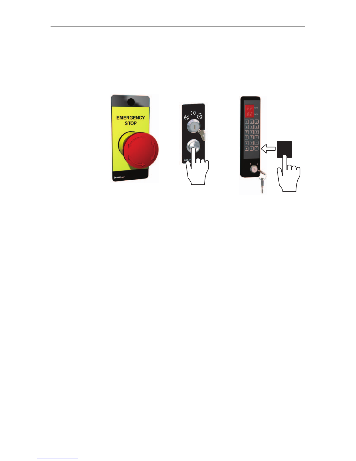
6.1.3 Emergency stop push-button
• The door rotation can be stopped by pressing the emergency stop push-button
• To reset the door to normal operation - release the emergency stop push-button
by rotating it in any direction and press the reset push-button or the C pushbutton on the PCD (if installed)
ILL-00044
ILL-00049
C
PCD
Page 13
Programme selector PCD
1003090-EI-2.0 Issued 2006-12-21 13
7.0 Programme selector PCD
As option the RD3/RD4 can be equipped with programme selector PCD (programme control device) with access codes to operate the door.
7.1 General information
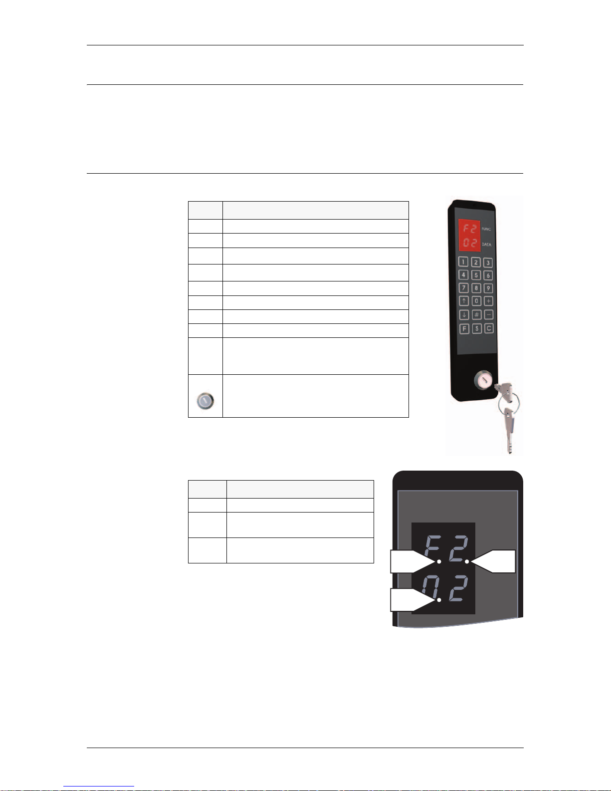
Information prompts on the display
The door has a lot of configurations, which
shall be left to Besam Service.
Key Function
0-9 Numeric inputs
# Confirm access code input
K
Setpoint selection upwards
L
Setpoint selection downwards
+ Setpoint value change upwards
- Setpoint value change downwards
F Function selection
S Setpoint confirmation and storage
C Error reset
Clear display
Leave menu
ON/OFF switch
Prompt Description
P1 ON/OFF switch in OFF position
P2 Service request. Call Besam for ser-
vice
P3 Real time operation ON, see “Real
time operation” on page 17
EAA154A
FUNC
DATA
ILL-00184
P1 P2
P3
Page 14

Programme selector PCD
14 Issued 2006-12-21 1003090-EI-2.0
7.2 Access code
To be able to operate the PCD a login of access code must be done.
7.2.1 Login to the PCD
1. Type # to clear the display.
2. Type the access code, delivery code 1234, with the number key (four digits).
The display shows ==.
3. Type # to confirm the input.
If the access code is correct the display shows:
L I (Login)
0 1 (Level 01)
In case of two unauthorized attempts to access the PCD it takes five minutes
before a new attempt can be made.
7.2.2 Logout from the PCD
1. Type # to clear the display.
2. Type the access code. The display shows ==.
3. Type # to confirm the input.
If the access code is correct the display shows:
LO (Logout)
0 1 (Level 01)
4. Automatic logout ten minutes after the last key stroke.
5. Automatic logout can be inhibited by typing F561 on the PCD.
7.2.3 Change access code
At delivery the access code is 1234. To change do as follows:
1. Type # 1234 #. If the access code is correct the display shows:
L I (Login)
0 1 (Level 01)
2. Type
F41. The display shows:
F 4
L 1
3. Type new code (4 digits).
4. Type S to confirm.
5. Type the new access code a second time.
6. Type S to confirm.
Page 15
Programme selector PCD
1003090-EI-2.0 Issued 2006-12-21 15
7.2.4 The ON/OFF switch
The ON/OFF switch can be used in any operating mode (except manual mode). If
the door is locked with this switch (OFF), the prompt P1 is shown on the display.
If the door is locked with the ON/OFF switch it can be opened with a key impulse
switch (ask your local Besam Service). When the key impulse switch is activated,
the door unlocks, runs 360° and locks again.
7.3 Changing operating mode
1. Login to the PCD.
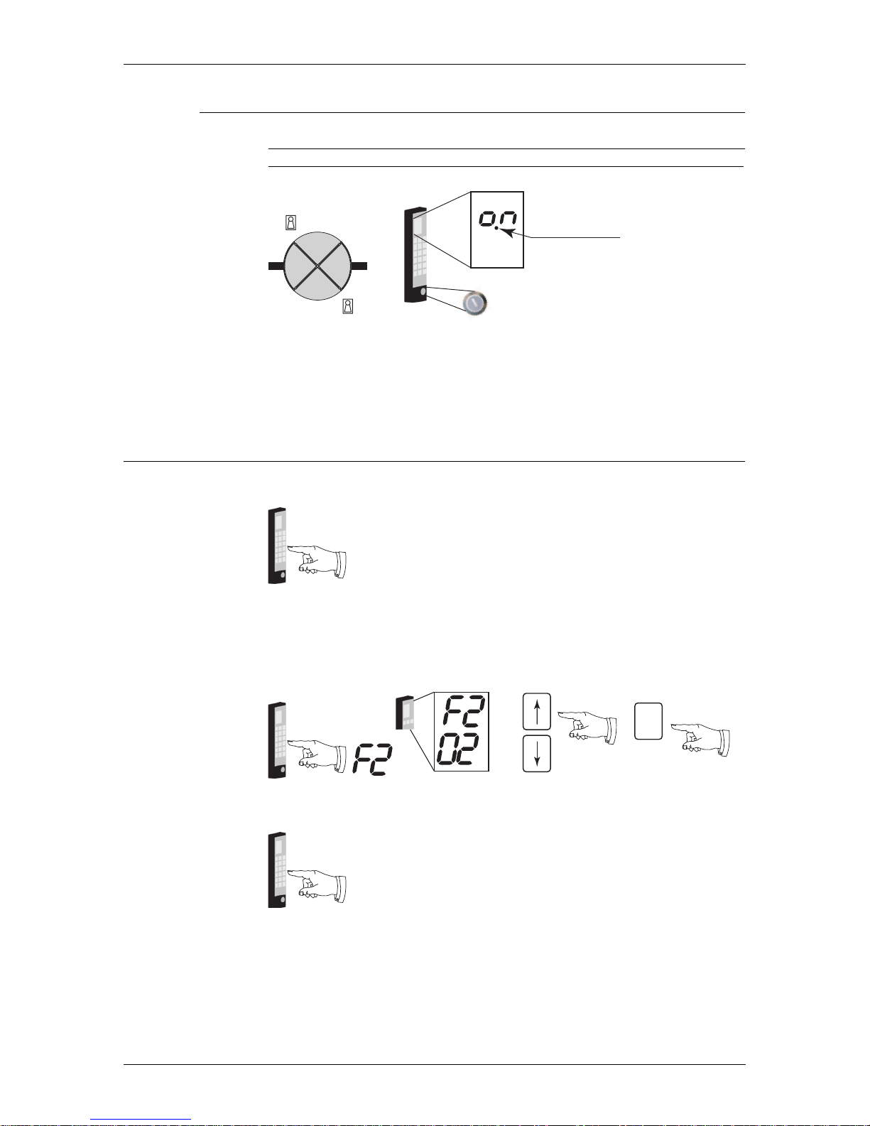
2. Type F2. The display shows F2 plus current operating mode.
3. Use the up or down arrow to change the operating mode.
4. Confirm the change and exit the operating mode selection function by typing
S.
5. Logout from the PCD (automatically Logout after 10 min)
ILL-00175
Key impulse switch
Key impulse switch
ON/OFF switch
Locked
ILL-00177
#Access code#
ILL-00182
S
ILL-00177
#Access code#
Page 16
Programme selector PCD
16 Issued 2006-12-21 1003090-EI-2.0
7.3.1 The different operating modes
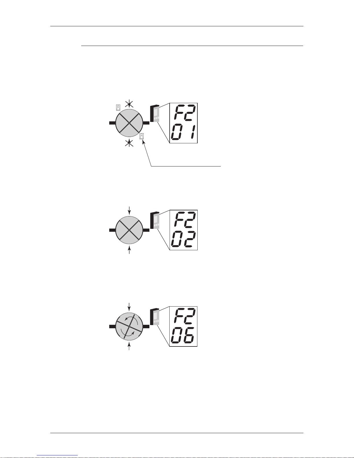
Closed (locked) 01
The door rotates to its closed position. If an electromechanical lock is fitted, the
lock is activated. The door can be opened with the key impulse switch, see “The
ON/OFF switch” on page 15. In this mode 01, the door will not run, even if the
ON/OFF switch is set to ON.
Automatic operation, start from open position 02
As soon as the outside or inside activation units detect approaching traffic, the
door starts rotating.
Continuous rotation 06
The door rotates at a low speed. As soon as the outside or inside activation units
detect approaching traffic, the door accelerates to normal speed. The door returns
to low speed when there is no traffic.
ILL-00180
Key impulse switch
ILL-00189
ILL-00190
Page 17
Programme selector PCD
1003090-EI-2.0 Issued 2006-12-21 17
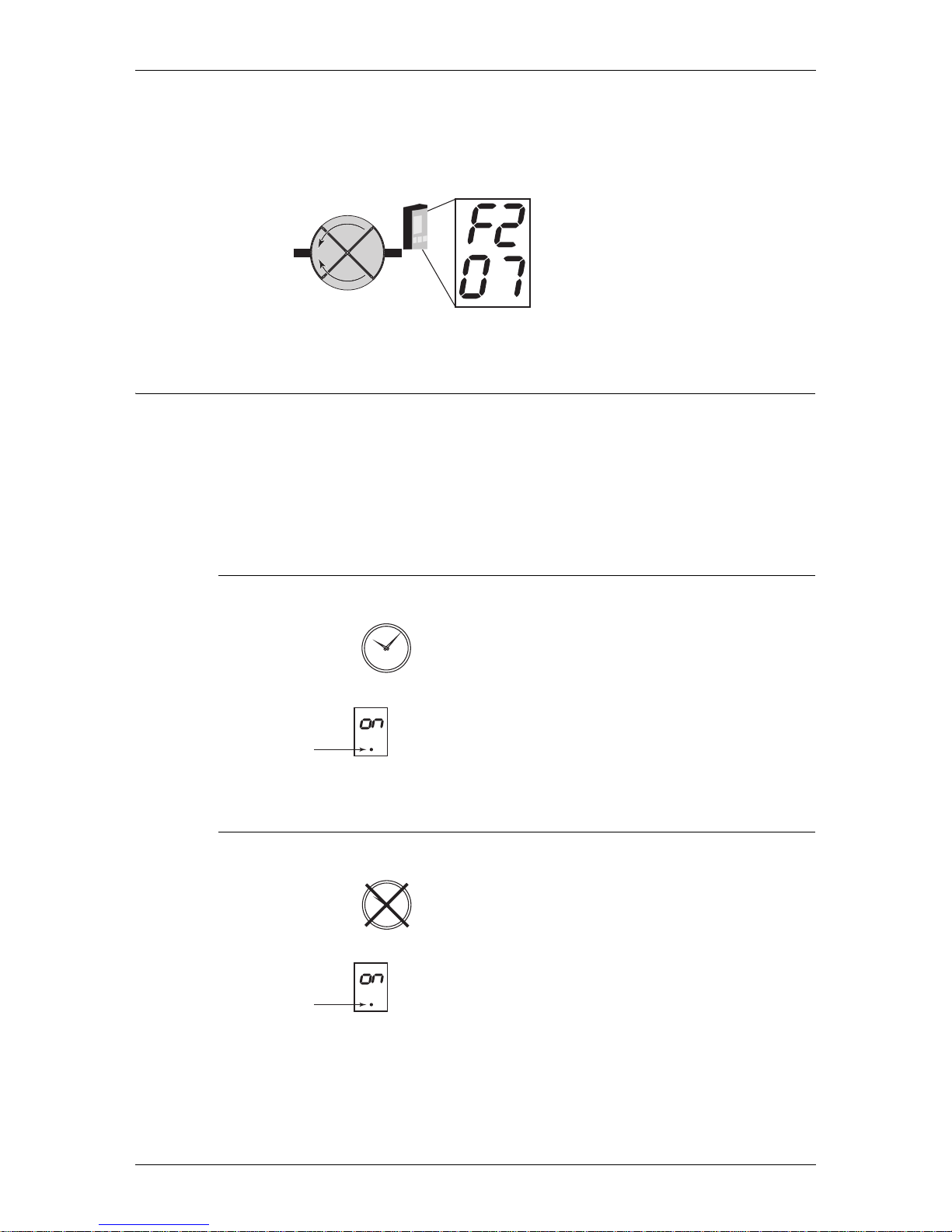
Manual operation “Cleaning position” 07
The door rotates forward as long as the + key is hold down and backwards as long
as the - key is hold down.
Note: During manual operation safety devices are disconnected.
7.4 Real time operation
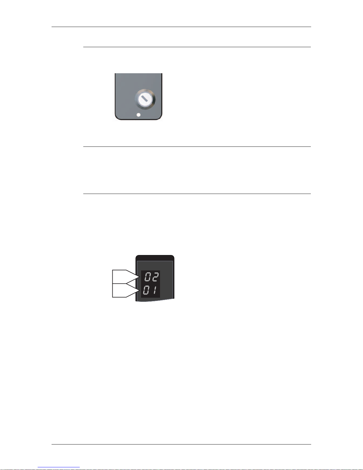
Programming of real time operation must be done by Besam service engineer. Fill
in form on page 34.
The CDC-system has three different day schedules. Each day schedule may contain up to 10 different operation modes. The week schedule informs the system of
which day schedule to run and in what order during a week. It is possible to make
up to 16 exceptions from this week schedule for e.g. public holidays etc.
7.4.1 Activation
1. Type F556 (Real time operation ON).
2. Prompt P3 lits up.
3. The door operates according to schedule.
7.4.2 Deactivation
1. Type F557 (Real time operation OFF).
2. Prompt P3 lits down.
3. The door operates according to manually set operation mode.
ILL-00191
+
-
F556 =
2
1
2
5
4
3
6
11
01
8
7
9
1
ILL-00181
ILL-00193
F557 =
2
1
2
5
4
3
6
11
01
8
7
9
1
ILL-00192
ILL-00193
Page 18
Programme selector PCD
18 Issued 2006-12-21 1003090-EI-2.0
7.4.3 ON/OFF
The OFF position overrides real time operation. The door will be locked. When the
key switch is ON, the door resume settings according to schedule.
7.4.4 Manually setting of operation mode
If the door is running in real time operation mode and the operation mode is manually changed, real time operation mode is automatically deactivated. To resume
real time operation mode it has to be reactivated by typing F556 again.
7.4.5 Summertime/Wintertime
1. To change from summertime to wintertime type F53 and select option number
02 with arrow ↑/↓ keys.
2. Press + or - to select setting 00 or 01, [summertime off (wintertime) is value
00 and summertime on is value 01].
3. Press S (select).
To check the time change (see “Read real time clock” on page 19).
EAA204
FUNC
DATA
EAA400
↑/↓
+/−
Page 19
Programme selector PCD
1003090-EI-2.0 Issued 2006-12-21 19
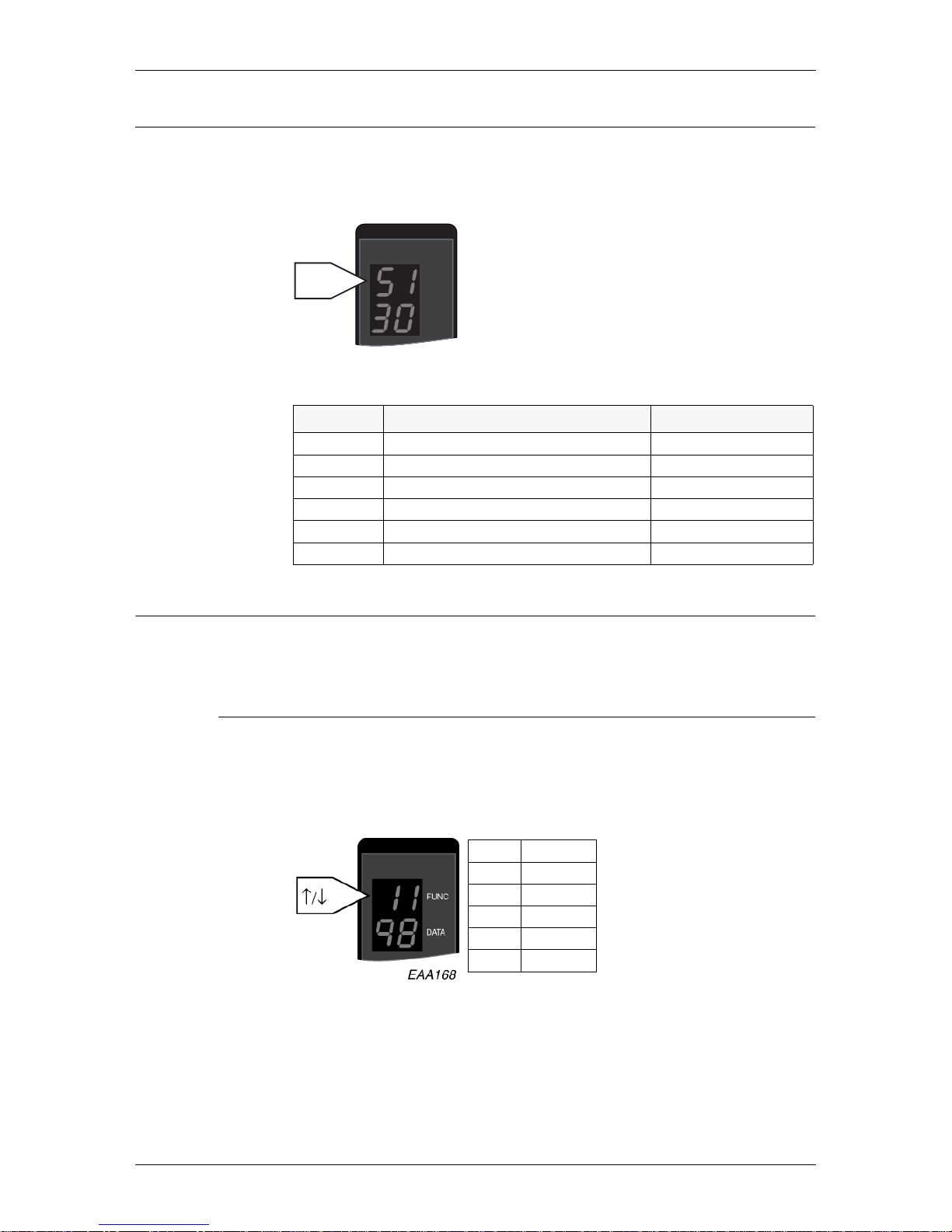
7.5 Read speed settings
1. Type F3. The display shows S1.
2. Use ↑ or ↓ to select setpoint number to read.
3. Press C to leave the menu.
7.6 Real time clock
The CDC system has a real time clock built in. The clock is used for the log
record and when the door is running under real time settings.
7.6.1 Read real time clock
1. Type F71. The display shows 11 and present parameter value relating to year.
2. Use ↑ or ↓ to select parameter number and display the parameter value.
3. Press C to leave the menu.
Summer and wintertime (see “Summertime/Wintertime” on page 18).
Setpoint Description Setpoint value
S1 High speed setpoint 1.0-6.0 rpm
S2 Low (handicap) speed setpoint 0.2-2.5 rpm
S3 Creep speed setpoint Fixed at 0.5 rpm
S4 Continuous speed setpoint 1.0-2.5 rpm
S5 Manual speed setpoint 0.2-2.0 rpm
S9 Door size parameter 1-9
FUNC
DATA
EAA254
↑/↓
11 Year
12 Month
13 Date
14 Hour
15 Minute
16 Second
Page 20
Programme selector PCD
20 Issued 2006-12-21 1003090-EI-2.0
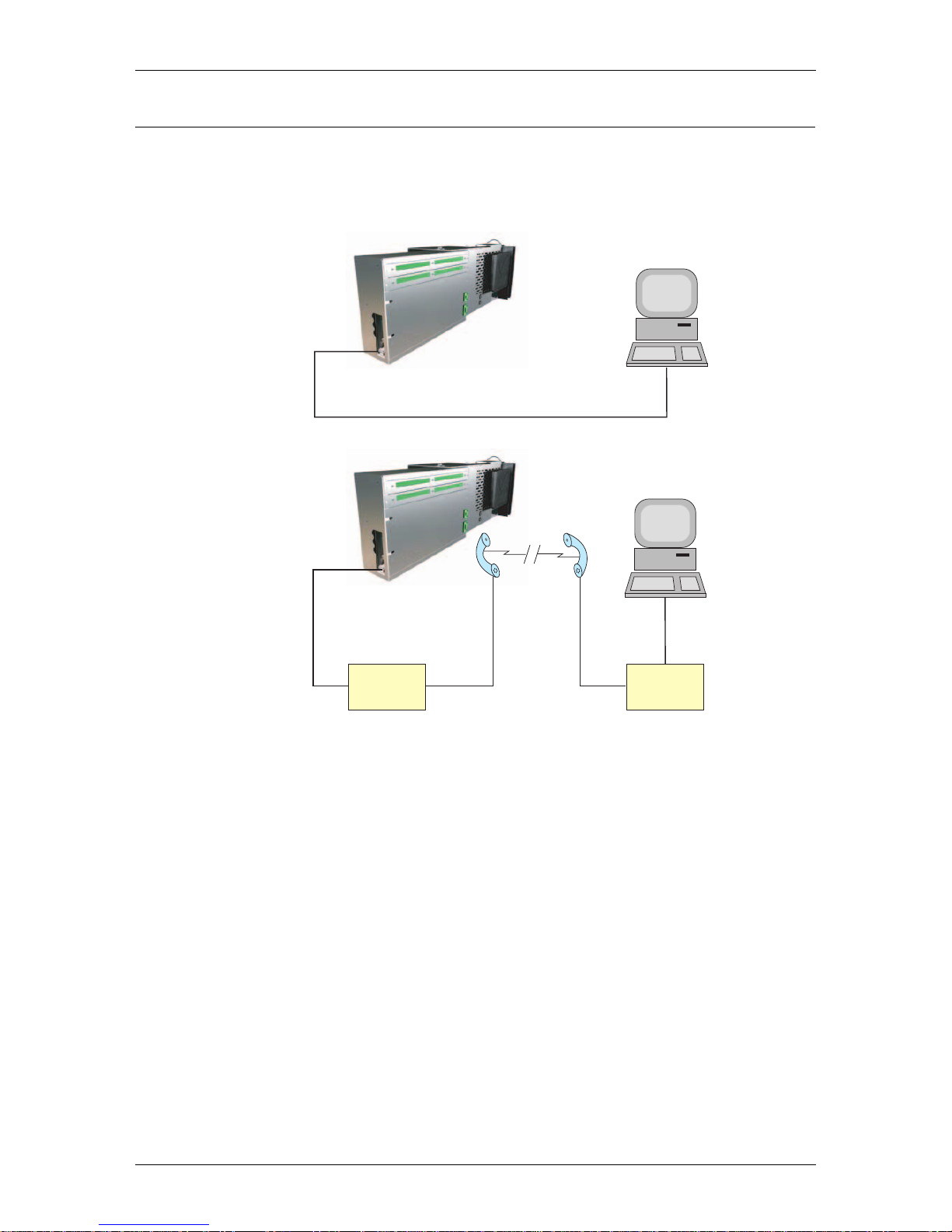
7.7 Remote Control Operation
To operate the door and have service control the CDC system can be connected to
a computer via the RS 232 connection “Read out”. It can be connected directly or
via a modem.
Ask your local Besam distributor for more information.
Software communication
To be able to communicate with the door Windows 3.1 or higher is needed. Make
following settings.
1. A)Windows 3.1/3.11.
Start terminal under Accessories.
B)Windows 95/98 or 2000XP.
Start hyperterminal under Accessories.
2. Make the following settings.
- Auto identification or VT100
- 8 bits data
- No parity
- One stop bit
- 9600 baud
EAA79
2
MODEM MODEM
Com. port
Page 21

Programme selector PCD
1003090-EI-2.0 Issued 2006-12-21 21
7.7.1 Communication ON/OFF
To allow/not allow this, the communication command has to be set to ON or OFF.
If no PCD is installed talk to your local Besam Service.
External communication ON
Type F552 on the PCD.
External communication OFF
Type F553 on the PCD.
7.7.2 Login
NOTE!
To enable login via a computer the PCD must be logged out.
At the CDC Login Menu type the access code and press enter. The CDC Main
Menu appears on the display.
7.7.3 Logout
Always logout properly, which means, press number key “6”. Logout on question
Logout Yes/No. Press “Y” key and terminate the connection.
7.8 Main menu
Press the “number key” 1 to get to the door operation page.
Press ESC to go to this menu from any sub menu.
CDC Main Menu
Door Type : RD3/RD4-CDC42
Software Release : Ver 1.00.02 P1 #xxxx 2005-05-01
Press key to select function :
1 : Door Operation
2 : Configuration
3 : Diagnostic Functions
4 : Log Functions
5 : Development Functions
6 : Logout
Page 22

Programme selector PCD
22 Issued 2006-12-21 1003090-EI-2.0
7.9 Door operation
Press the number key relating to the number in front of the desired operation
mode to select.
Press Enter to confirm changes.
Press ESC to return to main menu.
7.9.1 Other information on screen (EI)
Manually locked
The ON/OFF switch is in OFF position. It is not possible to give an impulse from
the terminal when the ON/OFF switch is in OFF position.
Service request
The door has been running for 300.000 revolutions.
Call fore service.
Real time
Real time operation is active.
Type R to toggle between real time operations ON/OFF.
Error/Status Display: ON
Operating Mode: 2 Real Time Mode 1
Door Speed (RPM/10): 0
Revolution Counter: 35552
Date & Time: Monday 2005-06-13 13:07:16
Operating modes:
1: Lock Door
2: Auto Open = Start from open position
6: Continuous Rotation
7: Manual Operation
Press function key: C: Error Clear
I: Key Impulse
R: Real Time Operation ON/OFF
Page 23
Maintenance
1003090-EI-2.0 Issued 2006-12-21 23
8.0 Maintenance
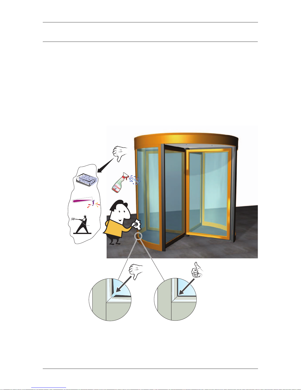
The fascia, windows and profiles must be subjected to regular inspection and
cleaning, the frequency of which is governed by the environmental conditions (at
least three times a year).
Cleaning
To maintain the quality of the enamel layer, the surfaces shall be cleaned three
times/year (once/four months period) with gentle (pH 5-9), non-polishing detergent and water. Use soft cloth or sponge. The cleanings shall be documented.
To avoid damages of the ceiling and the profiles the brushes must be vacuumcleaned weekly.
pH5-9
ILL-00066
Page 24
Options
24 Issued 2006-12-21 1003090-EI-2.0
9.0 Options
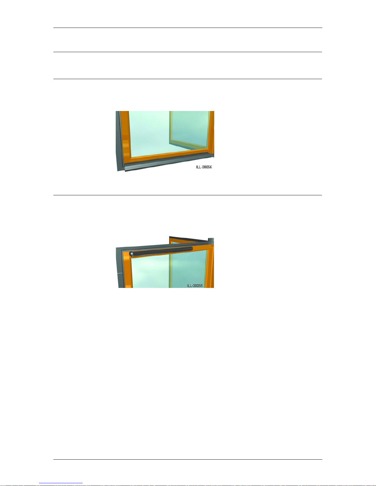
9.1 Compressible safety switches on the door leaves
If one of the safety switches, mounted on the door leaves, is compressed, the door
stops. When the obstacle is removed, the rotation starts.
9.2 Infrared presence sensor
Installed on the top of the door leaves provides safety over the whole height of the
door. If the sensor detects an obstacle the door stops or reduces speed to 0.5 rpm
(configurable). When the obstacle is removed, the rotation starts.
Page 25
Options
1003090-EI-2.0 Issued 2006-12-21 25
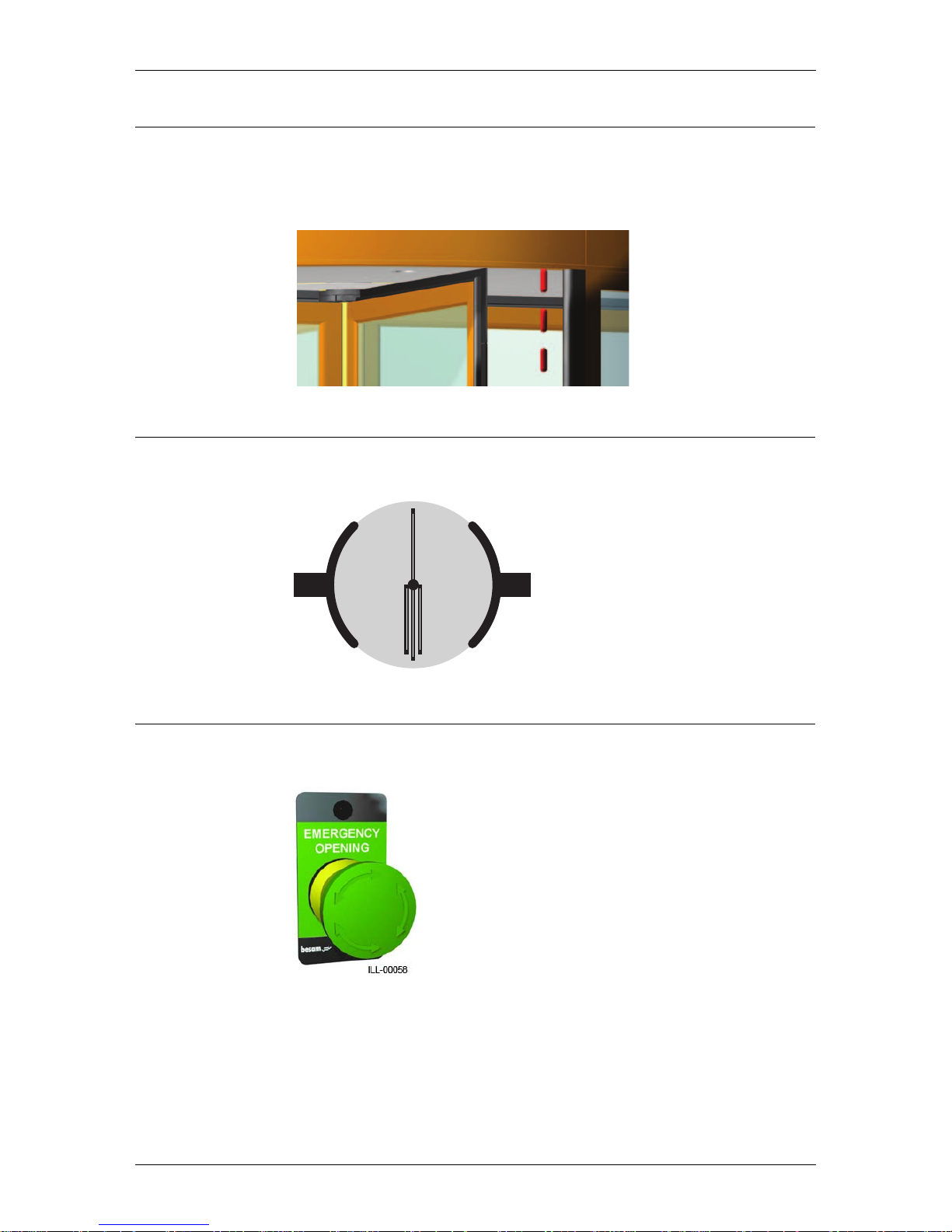
9.3 Vertical presence photocell sensor PDR
Vertical presence photocell sensor PDR located above the entrance on inner and
outer sides. If the beam is broken in the safety zone (approx. 25° from the drum
edge) the door stops. When the obstacle is removed the rotation starts.
9.4 Break-out kit
Enables the door leaves to be broken outwards in case of emergency.
9.5 Emergency opening push-button
To be used to activate “Break-out function”.
ILL-00059
Page 26
Options
26 Issued 2006-12-21 1003090-EI-2.0
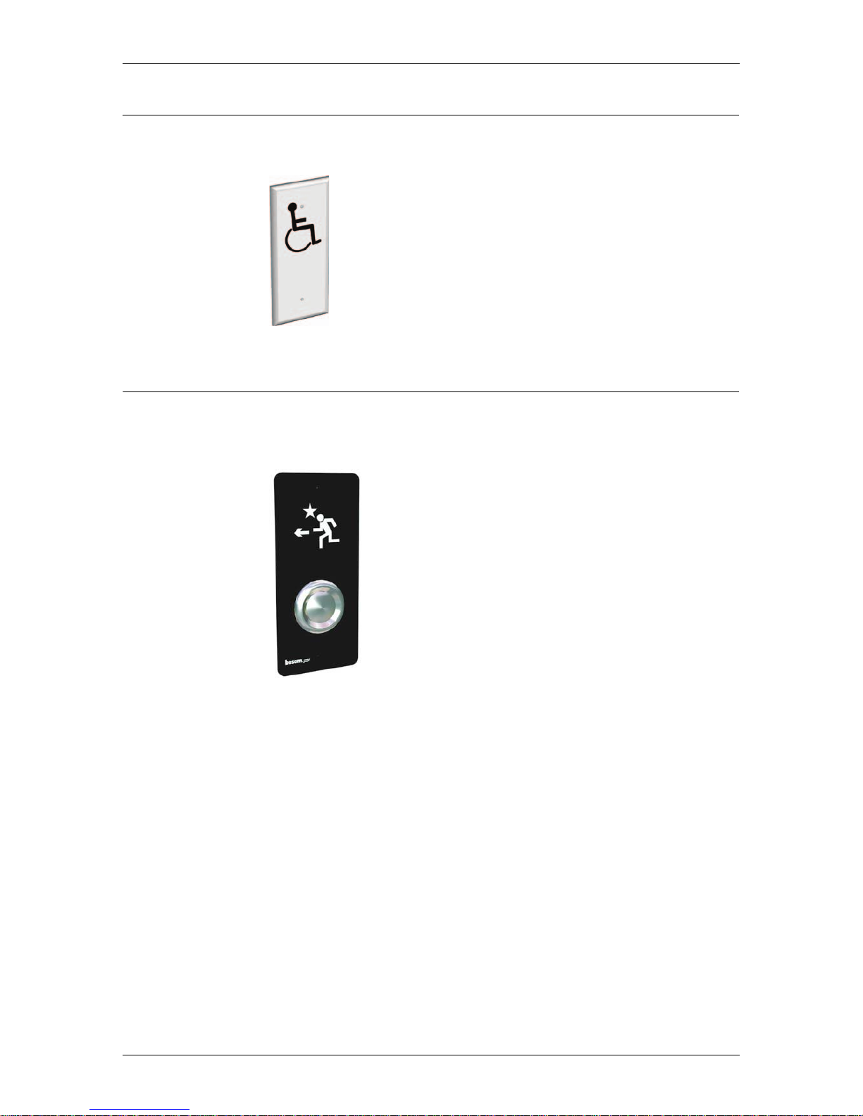
9.6 Push-button for disabled
Push-button to reduce speed of the door.
9.7 Push-button inside door
In case somebody is trapped in a compartment, the door can be opened by pushing this button, placed inside on the mid post.
ILL-00050
Page 27
Accessories
1003090-EI-2.0 Issued 2006-12-21 27
10.0 Accessories
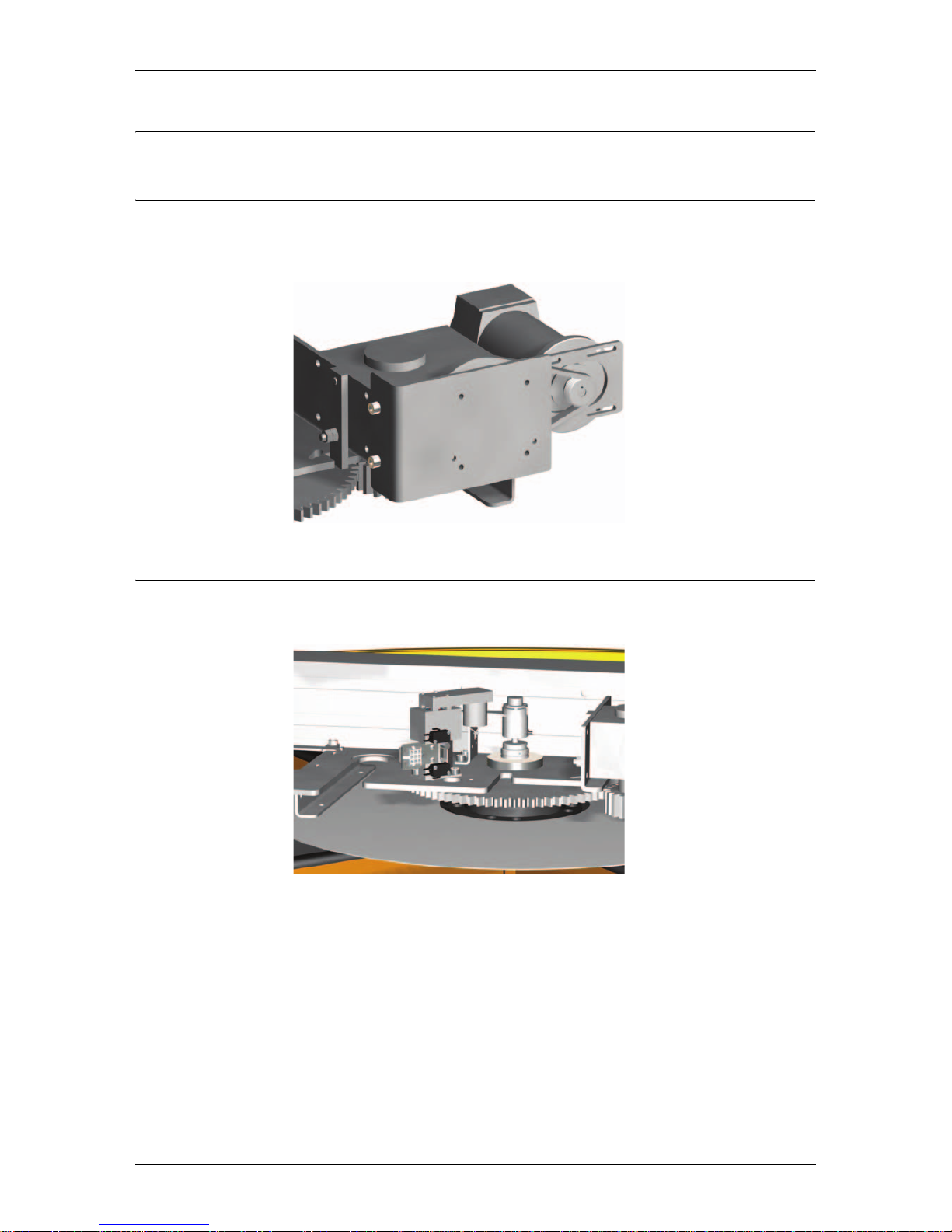
10.1 Rotation brake (lock)
The rotation brake, brakes the door in parked position. The brake can also be activated with a key switch or push-button for immediate stop of the door.
10.2 Electromechanical lock
The electromechanical lock, locks the door in home position.
ILL-00052
ILL-00051
Page 28
Accessories
28 Issued 2006-12-21 1003090-EI-2.0
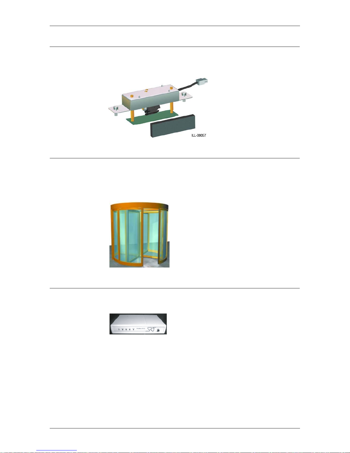
10.3 Direction sensing radar DSR
The radar DSR is direction sensing i.e. it triggers an opening impulse for
approaching objects only, but not for objects leaving the door.
10.4 Night closing door NCD
Two versions are available:
• manually operated
• automatically operated
10.5 Modem
Used for remote troubleshooting or operation of the door, by calling the modem.
ILL-00065
Page 29
Troubleshooting
1003090-EI-2.0 Issued 2006-12-21 29
11.0 Troubleshooting
11.1 Supervision system
The RD3/RD4 has a built-in supervision system.
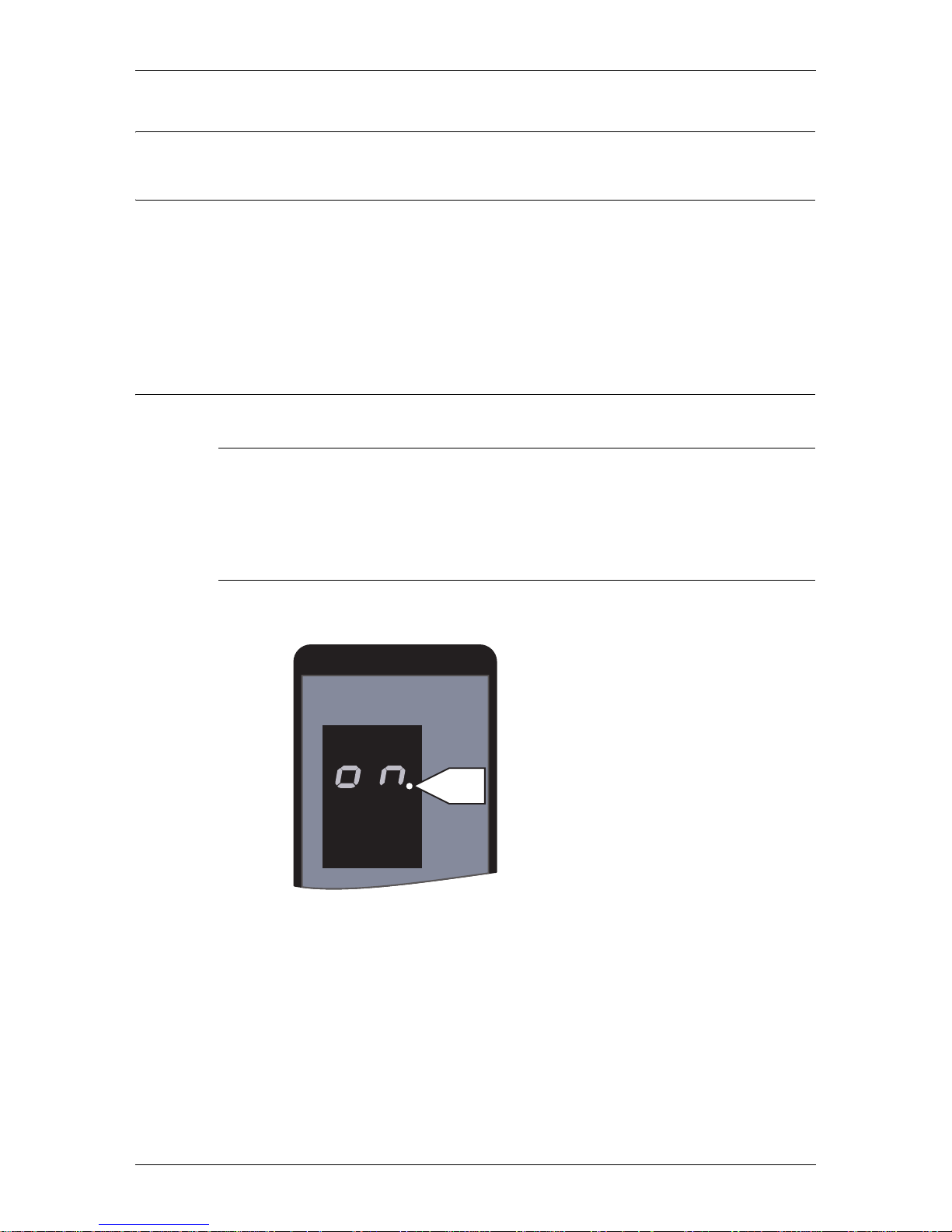
If an error occurs, the PCD display will show an error or status code. During normal operation the display will show “
ON”. All error codes are shown by flash-
ing figures, status codes with permanent figures. The exceptions are code 20 and
30, which will be shown flashing. To reset the door to normal operation after a
flashing error code, type C on the PCD (see “Code list” on page 30).
11.2 Simple troubleshooting
11.2.1 The door does not start at start up
Make sure that the PCD display shows “ON”, and that mains power to the door
is on.
Check the operating mode, see “The ON/OFF switch” on page 15.
11.2.2 Service request
Prompt P2 indicates that it is time for service.
FUNC
DATA
P2
Page 30

Troubleshooting
30 Issued 2006-12-21 1003090-EI-2.0
11.3 Code list
For all other error codes call Besam Service.
Code Statu s Cause Remedy
ON The revolving door is function-
ing normally
10 Stop Check for obstacles between the
wing and the floor and between the
wing and the inside of the drum.
Check trip switches. Close escape
doors
11 Electromechanical lock error No signal from the electro-
mechanical lock
Make one more unlock/lock operation. If that does not help call
Besam Service
20 Emergency stop Emergency stop push-button
depressed
Release the button by turning it in
the direction of the arrows, then
restore function by striking C on
the PCD
21 Response from the PDR sensor
fitted above the opening on the
inside
Inner PDR sensor activated Remove obstacle in the inner detec-
tion zone. Adjust the inner detection zone if necessary
22 Response from the PDR sensor
fitted above the opening on the
outside
Outer PDR sensor activated Remove obstacle in the outer detec-
tion zone. Adjust the outer detection zone if necessary
25 Response from the sensors on
the door leaves
The detection zone of the sensor
activated
Remove obstacle in the detection
zone. Adjust the detection zone if
necessary
26 Response from the sensors on
the door leaves
The detection zone of the sensor
activated
Remove obstacle in the detection
zone. Adjust the detection zone if
necessary
30 Blocked door The wing is blocked by an obsta-
cle
Check for obstacles between the
wing and the floor and between the
wing and the inside of the drum.
After checking press C
32 Power fail input Main power lost Check main fuse.
Check external power supply
Page 31
Troubleshooting
1003090-EI-2.0 Issued 2006-12-21 31
11.4 Status codes
11.4.1 Diagnostic out-put
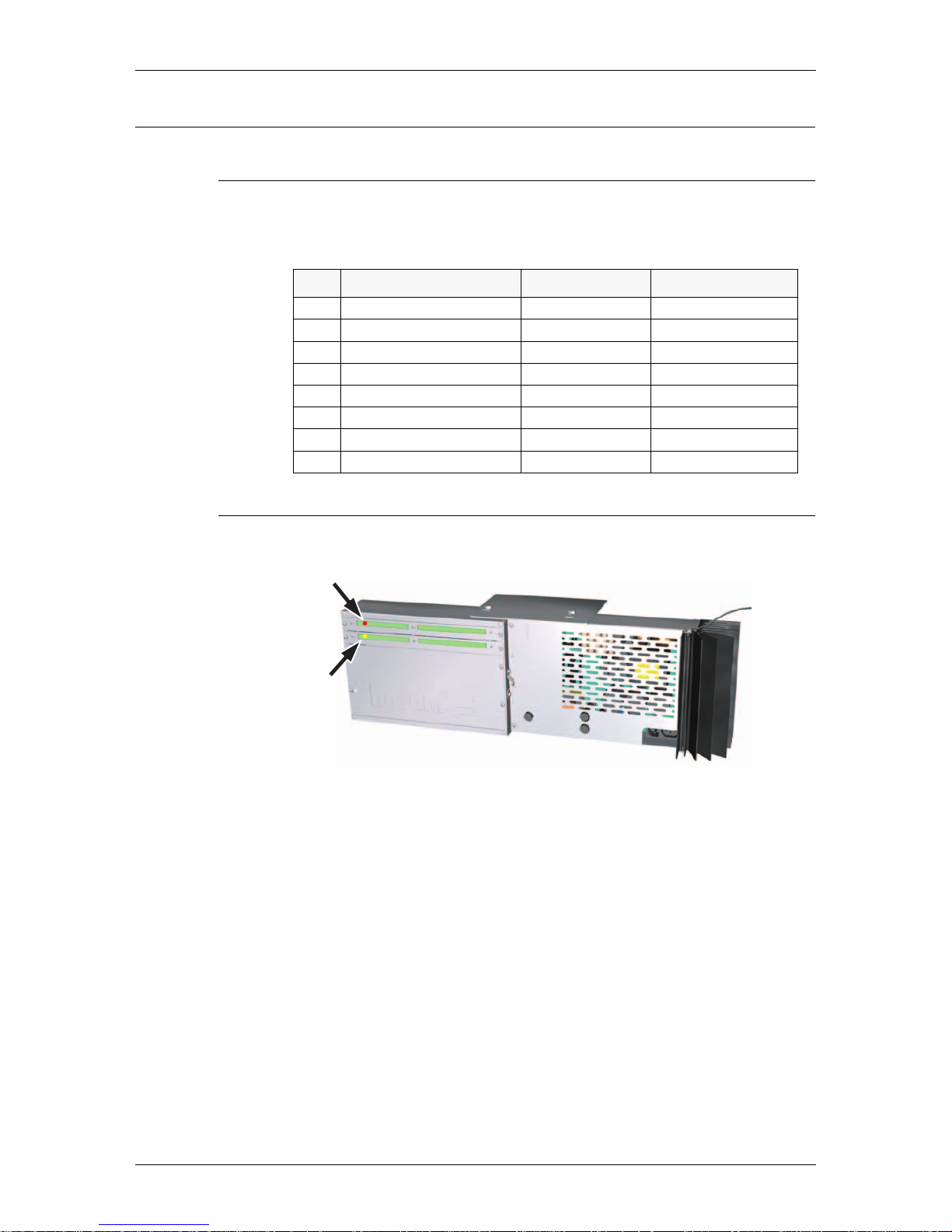
It is possible to monitor the system by looking at the red and yellow out-put
LED’s on the control unit CDC.
11.4.2 Control unit CDC
Cause I/OA-1 (red LED) I/OA-2 (yellow LED)
10 Safety stop Fixed light
20 Emergency stop Fixed light
30 Blocked door Fixed light Fixed light
21-22 Vertical sensors activated Flashing light
C2 Bok magnet Flashing light
9A Overheat Flashing light Flashing light
11 Electromechanical lock Fixed light Flashing light
06-07 Encoder error Flashing light Fixed light
ILL-00077
I/OA-1
I/OA-2
Page 32

Mark up table
32 Issued 2006-12-21 1003090-EI-2.0
12.0 Mark up table
12.1 Floor levelling information from installation
12.1.1 Floor surface levelling values
Point Point 1 value Val ue Deviation
1
2
3
4
5
6
7
8
9
10
11
12
13
O8
2
13
1
10
5
6
3
4
7
9
11
12
ILL-00196
Page 33

Revolving door log book
1003090-EI-2.0 Issued 2006-12-21 33
13.0 Revolving door log book
Date Remark Sign
Page 34

Real time operation
34 Issued 2006-12-21 1003090-EI-2.0
14.0 Real time operation
Day schedule
Week schedule
Exceptions
Day schedule 1 Day schedule 2 Day schedule 3
111
222
333
444
555
666
777
888
999
10 10 10
Week day Schedule
Monday
Tuesday
Wednesday
Thursday
Friday
Saturday
Sunday
Start exception End exception Exception schedule
111
222
333
444
555
666
777
888
999
10 10 10
11 11 11
12 12 12
13 13 13
14 14 14
15 15 15
16 16 16
Page 35

Real time operation
1003090-EI-2.0 Issued 2006-12-21 35
Page 36

An ASSA ABLOY Group company
Besam Production AB, Box 668, SE-261 25 Landskrona.
Tel: +46 418 512 00 Fax: +46 418 512 68
[email protected] • www.besam.com
ASSA ABLOY is the world's leading manufacturer and supplier of locking solutions, meeting tough end-user demands for safety, security and user friendliness.
Australia:
Besam Australia Pty Ltd.,
8 Nicholas Drive, Dandenong,
3175 Victoria
Tel: +61 3 9706 4886
Fax: +61 3 9706 4906
[email protected]
Austria:
Besam Austria GmbH,
Hütteldorferstraße 216c,
1140 Wien
Tel: +43 1 914 55 37 0
Fax: +43 1 914 92 98
[email protected]
Belgium:
Besam Belgium NV,
Centrum-Zuid 3042,
3530 Houthalen
Tel: +32 11 609 500
Fax: +32 11 604 680
[email protected]
Canada:
Besam Canada, Inc.,
4090 Ridgeway Dr. Unit #16,
Mississauga, Ontario
L5L 5X5 Canada
Tel: 905 608 9242
Fax: 905 608 1151
[email protected]
China:
Besam Automatic Door Systems
Trading (Shanghai) Co. Ltd.,
Suite 1903, Modern Communication
Commercial Tower
218, Hengfeng Road,
Shanghai, PRC 200070
Tel: +86 21 5128 8909
Fax: +86 21 5128 8919
[email protected]
Czech Republic:
Besam spol. s r.o.,
Košarova 23,
197 00 Praha - Kbely
Tel: +420 2 8600 1560
Fax: +420 286 001 570
[email protected]
Denmark:
Besam A/S,
Marielundvej 20,
2730 Herlev
Tel: 44 53 70 80
Fax: 44 53 20 22
[email protected]
Finland:
Besam OY,
Agronominraitti 2,
00790 Helsinki
Tel: +358 9 7288 5400
Fax: +358 9 799 292
[email protected]
France:
Besam S.A.S,
10 Rond Point du Général de Gaulle,
94864 Bonneuil s/Marne Cedex
Tel: +33 1 43 77 55 66
Fax: +33 1 43 39 56 00
[email protected]
Germany:
Besam GmbH,
Lagerstraße 45,
64807 Dieburg
Tel: +49 6071 2080
Fax: +49 6071 208 111
[email protected]
Hungary:
Besam Kft.,
Nagytétényi út 112,
1222 Budapest
Tel: +36 1 424 7274
Fax: +36 1 226 1949
[email protected]
Italy:
Besam S.p.A.,
Via Monzoro 142,
20010 S
Pietro all’Olmo (MI)
Tel: +39 02 936 11 311
Fax: +39 02 936 21 16
[email protected]
Netherlands:
Besam Nederland BV,
Postbus 8155
6710 AD Ede
Tel: +31 318 69 89 69
Fax: +31 318 63 83 46
[email protected]
New Zealand:
Doorman Besam Ltd.,
10 Haultain St.,
PD Box 15 784 New Lynn,
Auchland 1232
Tel: +64 (0)9 815 8392
Fax: +64 (0)9 815 8391
[email protected]
Northern Ireland:
Tel: +44 (0) 28 71 26 80 11
Fax: +44 (0) 28 71 27 11 15
info@besam .co.uk
Poland:
Besam Polska Sp. z.o.o.,
ul. Rydygiera 12,
01-793 Warszawa
Tel: +48 22 331 86 80
Fax: +48 22 331 86 81
[email protected]
Portugal:
Besam Portugal,
Rua Duarte Leite,
41 2820-220 Charneca da Caparica
Tel: +351 212 969 290
Fax: +351 212 974 132
[email protected]
Republic of Ireland:
Besam Ltd,
unit 39, Navan Enterprise Centre,
Trim Road
Navan, Co. Meath
Tel: +353 46 76747
Fax: +353 46 76745
[email protected]
Russia:
ASSA ABLOY AB representation office
Bolshoy Savvinskiy pereulok 4
Build. 4
Moscow 119435
Tel: +7 495 780 04 44
Fax: +7 495 780 07 46
[email protected]
Singapore:
Besam (Mfg) Pte Ltd.,
152 Ubi Ave. 4 #02-02, Armorcoat
Tec h B ldg
Singapore 408826
Tel: +65 6745 6228
Fax: +65 6745 7322
[email protected]
Slovak Republic:
Besam, spol. s.r.o.,
Kapitulská 15,
811 01 Bratislava
Tel: +421 254 431 045
Fax: +421 254 431 247
[email protected]
Spain:
Besam Ibérica S.A.,
C/Reyes Católicos, 6
28108 P.I. de Alcobendas (Madrid)
Tel: +34 91 657 48 60
Fax: +34 91 661 43 80
[email protected]
Sweden:
Besam Sverige AB,
Box 353
261 23 Landskrona
Tel: +46 418 510 00
Fax: +46 418 140 60
[email protected]
Besam Export AB
Box 669,
261 25 Landskrona
Tel: +46 418 514 00
Fax: +46 418 513 55
[email protected]
United Kingdom:
Besam Ltd.,
Washington House,
Brooklands Close,
Sunbury on Thames,
Middlesex TW16 7EQ
Tel: +44 1932 765 888
Fax: +44 1932 765 864
[email protected]
US:
Besam US Inc.,
1900 Airport Road,
Monroe, NC 28110
Tel: +1 704 290 5520
Fax: +1 704 290 5555
[email protected]
Parent company:
ASSA ABLOY Entrance Systems AB,
Box 131
261 22 Landskrona
Tel: +46 418 511 00
Fax: +46 418 238 00
 Loading...