

Page 1
FIXTURE INSTALLATION GUIDE
Model B0001wet, B0002wet, B0003wet, B0004wet
(Outdoor Wall Sconces 120V)
B0001wet,B0002wet,B0003wet,B0004wet, Rev.3 8-10
CAUTION: Turn off power to electrical box before installing
6695 Taylor Rd. Blacklick, OH 43004
www.besalighting.com
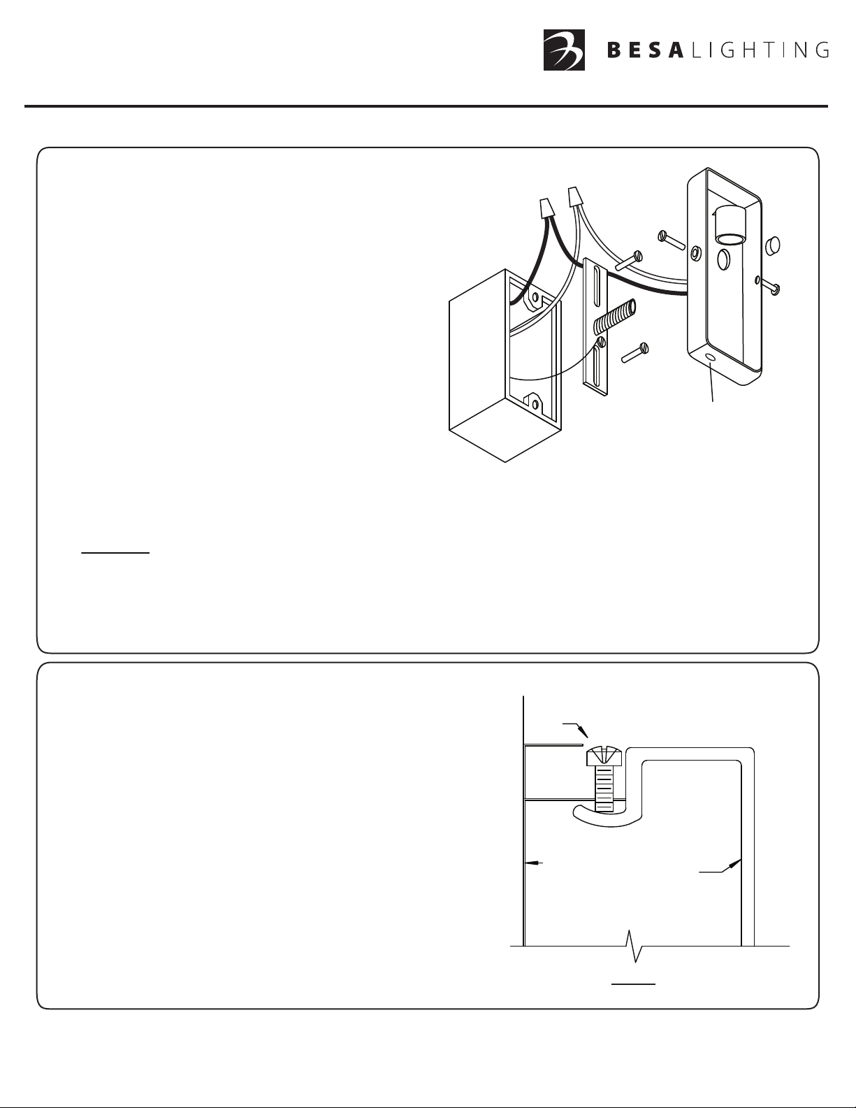
1. Disconnect power to outlet box at main electric box.
2. Fasten the mounting strap (A) to the outlet box using
machine screws (B) which should be found in the box.
3. Turn the threaded nipple (C) into the center hole in the
mounting strap.
4. Attach the branch circuit ground wire (I) to the green
screw on the mounting strap.
5. Hold the fixture canopy (E) close to the outlet box and
connect the fixture wires to the house supply wires
(black to black and white to white). Tighten securely
with wire nuts (D). Carefully push wires and wire nuts
back into the box.
6. Place the fixture canopy against the wall over the outlet
box oriented with the drainhole down of the canopy,
so that the threaded nipple protrudes through the hole on
the canopy. Place the cap nut (F) onto the threaded nipple
and tighten securely.`
D
H
B
C
I
A
Drainhole down
E
F
7. Partially install the retaining screws (H) into the canopy.
8. IMPORTANT: IN ORDER TO COMPLY WITH ESTABLISHED ELECTRICAL CODE, THE INSTALLER MUST SEAL
THE AREA AROUND THE FIXTURE CANOPY, BETWEEN THE CANOPY AND THE WALL, WITH A TYPE OF
CAULKING COMPOUND SUCH AS SILICONE RUBBER TO PROVIDE A WATERTIGHT SEAL IN ACCORDANCE
WITH THE DIFFERING SURFACE TEXTURES OF THE WALL.
9. With the power still off, insert bulb of not more than the recommended wattage.
GLASS INSTALLATION
10. Place the glass/metal frame unit to the canopy (E). Seat the
neck of glass with metal frame (G) fully into the canopy (see
Fig.A ). Then secure by tightening the set screw (H) to be sure
the glass/metal frame is fully seated into the canopy.
DO NOT OVERTIGHTEN THE RETAINING SCREWS, MAY CAUSE
DAMAGE TO GLASS.
11. Restore the power.
Screw
(H)
Canopy
(E)
Glass/
Metal
Frame
(G)
Fig. A
All electrical connections and the installation of this fixture must be in agreement with local codes, ordinances or
the NEC (National Electric Code) or CEC (Canadian Electrical Code). Do not connect this fixture to an electrical system
that does not provide a means for equipment grounding.
Page 2
FIXTURE INSTALLATION GUIDE
Models using B0005 or B0006 Backplate (Exterior Wall Sconce 120V)
B0005,B0006, Rev.3 8-10
CAUTION: Turn off power to electrical box before installing
6695 Taylor Rd. Blacklick, OH 43004
www.besalighting.com
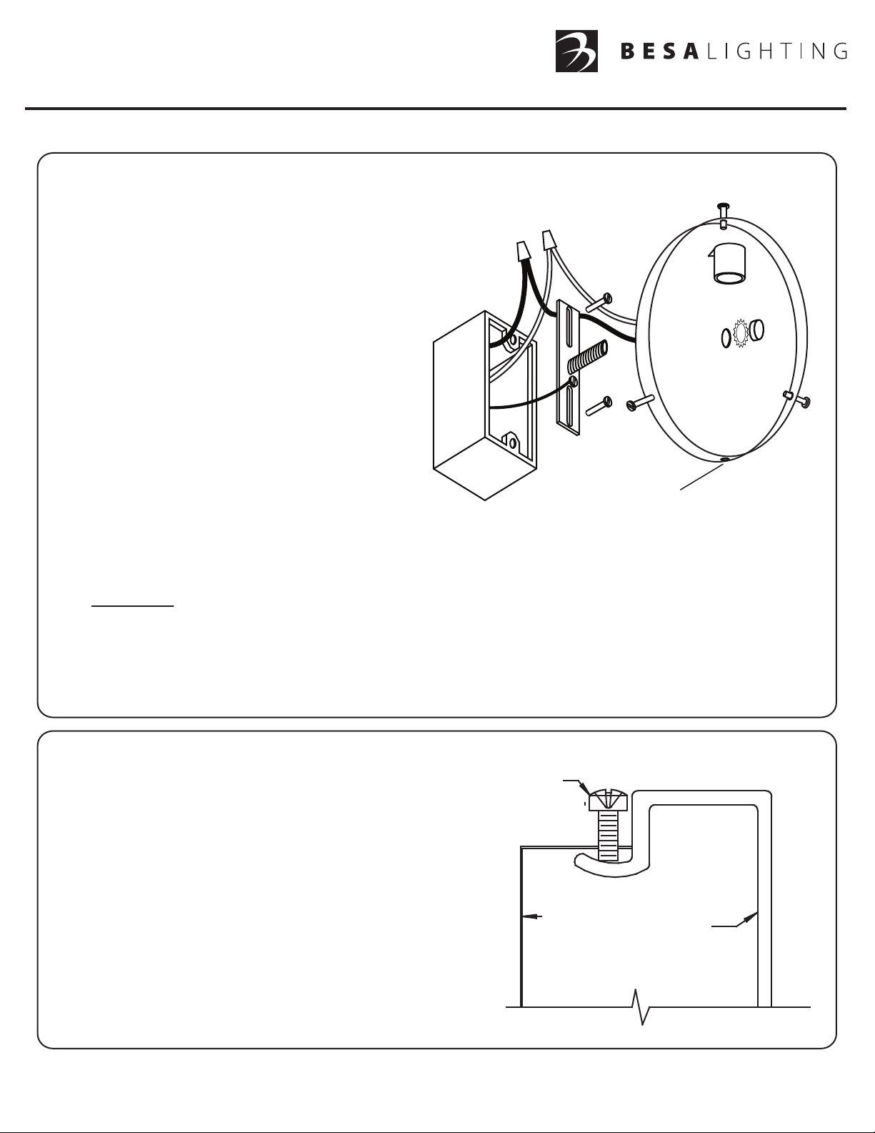
1. Disconnect power to outlet box at main electric box.
G
2. Fasten the mounting strap (A) to the outlet box using
machine screws (B) which should be found in the box.
D
3. Turn the threaded nipple (C) into the center hole
in the mounting strap.
4. Connect the supply ground wire (I) to the
B
F
green screw on the mounting strap.
C
5. Hold the fixture canopy (E) close to the outlet box
and connect the fixture wires to the house supply
wires (black to black and white to white). Tighten
securely with wire nuts (D). Carefully push wires
and wire nuts back into outlet box.
I
A
G
E
6. Place the fixture canopy against the wall over the
outlet box oriented with the drainhole down,
so that the threaded nipple protrudes through the
hole on the canopy. Place the cap nut and star
Drainhole down
washer(F) onto the threaded nipple and tighten securely.
7. Partially install the retaining screws (G) into the canopy. The number of retaining screws will vary dependant
upon the fixture model.
8. IMPORTANT: IN ORDER TO COMPLY WITH ESTABLISHED ELECTRICAL CODE, THE INSTALLER MUST
SEAL THE AREA AROUND THE FIXTURE CANOPY, BETWEEN THE CANOPY AND THE WALL WITH A
TYPE OF CAULKING COMPOUND SUCH AS SILICONE RUBBER TO PROVIDE A WATERTIGHT SEAL
IN ACCORDANCE WITH THE DIFFERING SURFACE TEXTURES OF THE WALL.
G
9. With the power still off, insert bulb(s) of not more than the recommended wattage.
GLASS INSTALLATION
Screw
(G)
10. Place the glass unit to the previously installed canopy (E).
Seat the neck of glass fully into the canopy (see Fig.A ).
Press against the glass while tightening the retaining
screws (G) to be sure the glass is fully seated into
the canopy (see Fig.A ).
DO NOT OVERTIGHTEN THE RETAINING SCREWS,
MAY CAUSE DAMAGE TO GLASS.
Canopy
(E)
Glass
11. Restore the power.
All electrical connections and the installation of this fixture must be in agreement with local codes, ordinances or
the NEC (National Electric Code) or CEC (Canadian Electrical Code). Do not connect this fixture to an electrical system
that does not provide a means for equipment grounding.
Page 3

FIXTURE INSTALLATION GUIDE
Models using B0008 or B0009 Backplate (Exterior Wall Sconce 120V)
B0008,B0009_Rev.4 7-12
CAUTION: Turn off power to electrical box before installing
6695 Taylor Rd. Blacklick, OH 43004
www.besalighting.com
1. Disconnect power to outlet box at main electric box.
G
2. Fasten the mounting strap (A) to the outlet box using
machine screws (B) which should be found in the box.
D
3. Turn the threaded nipple (C) into the center hole
in the mounting strap.
4. Connect the supply ground wire (I) to the
B
F
green screw on the mounting strap.
5. Hold the fixture canopy (E) close to the outlet box
and connect the fixture wires to the house supply
wires (black to black and white to white). Tighten
securely with wire nuts (D). Carefully push wires
and wire nuts back into outlet box.
6. Place the fixture canopy against the wall over the
I
G
A
E
outlet box oriented with the drainhole down, so
that the threaded nipple protrudes through the hole
on the canopy. Place the cap nut and star washer(F)
onto the threaded nipple and tighten securely.
Drainhole down
7. Partially install the retaining screws (G) into the canopy.
The number of retaining screws will vary dependant upon the fixture model.
8. IMPORTANT: IN ORDER TO COMPLY WITH ESTABLISHED ELECTRICAL CODE, THE INSTALLER MUST
SEAL THE AREA AROUND THE FIXTURE CANOPY, BETWEEN THE CANOPY AND THE WALL WITH A
TYPE OF CAULKING COMPOUND SUCH AS SILICONE RUBBER TO PROVIDE A WATERTIGHT SEAL
IN ACCORDANCE WITH THE DIFFERING SURFACE TEXTURES OF THE WALL.
G
9. With the power still off, insert bulb(s) of not more than the recommended wattage.
GLASS INSTALLATION
Screw
(G)
10. Place the glass unit to the previously installed canopy (E).
Seat the neck of glass fully into the canopy (see Fig.A ).
Press against the glass while tightening the retaining
screws (G) to be sure the glass is fully seated into
the canopy (see Fig.A ).
DO NOT OVERTIGHTEN THE RETAINING SCREWS,
MAY CAUSE DAMAGE TO GLASS.
Canopy
(E)
Glass
11. Restore the power.
All electrical connections and the installation of this fixture must be in agreement with local codes, ordinances or
the NEC (National Electric Code) or CEC (Canadian Electrical Code). Do not connect this fixture to an electrical system
that does not provide a means for equipment grounding.
 Loading...