

Page 1

Instruction Manual
For
MDU12i
12 port Intelligent Mains Distribution Unit
Page 2

DOC32 Page 2 of 41 Issue 2 30 NOV 17
This page is intentionally blank
Page 3

DOC32 Page 3 of 41 Issue 2 30 NOV 17
Contents
1.0 Description
2.0 Installation
3.0 Operation
4.0 Connections
5.0 Indication
6.0 Characteristics
Appendix A Web server HTML page description
Appendix B SNMP trap setup and register description
Appendix C Telnet command line interface description
Page 4

DOC32 Page 4 of 41 Issue 2 30 NOV 17
This page is intentionally blank
Page 5

DOC32 Page 5 of 41 Issue 2 30 NOV 17
1.0 Description
The DEM Intelligent Mains Distribution Unit [iMDU] is a meter grade 12 outlet power
distribution product housed within a 1U 19” sub-rack.
The main function of the product is to distribute a single phase mains power supply to 12
socket outlets while monitoring voltage, current, power and energy usage to a
meter grade accuracy of ± 1%. Additionally the product can monitor external environmental
conditions, temperature or humidity, contact inputs, 0-5VDC analogue inputs and control
voltage free contact outputs. The product is controlled remotely over an Ethernet network
using the integrated web server, SNMP registers or Telnet command interface. The product
provides the following features:
Single phase 16A capable ± 1% accuracy metering.
Monitoring of VRMS, IRMS, kW, kWh, Power factor, kVA, kgCO2, BTU/h, kJ/h and
frequency measurements.
Ethernet port [IEEE 802.3 with full 10/100Base-T network compatibility].
High-speed MODBUS RS485 port for local daisy-chaining of up to 31 iMDU slaves.
Temperature sensor bus [8x chained] + Humidity/Temperature sensor port.
External GPIO contact monitoring inputs x8.
External GPIO 0-5VDC analogue inputs x2.
External GPIO voltage free N.O. 1A @ 48VAC/DC relay output x2.
12 socket outlets with 16A N.O. switching and fuse blown monitoring.
USB Type ‘A’ port with 1A @ 5VDC power output.
Remote monitoring and configuration [HTML webserver, SNMP registers and Telnet
command interface].
Physical layout
The product is enclosed within a 1U 19” sub-rack with a mains inlet/outlet, illuminated front
panel mounted isolator switch, 12x IEC outlets and main interface connectors on the rear
panel and USB port, 12x fuses and power/fuse blown LED indication on the front panel.
The product is made up of a ‘Control’ PCB assembly which consists of a front panel
removable processor and mains power supply PCB that plugs into (hot swappable) a fixed
rear mounted meter and interface PCB.
Page 6

DOC32 Page 6 of 41 Issue 2 30 NOV 17
This page is intentionally blank
Page 7

DOC32 Page 7 of 41 Issue 2 30 NOV 17
2.0 Installation
Installation should be performed by a suitably competent person.
The MDU12i (iMDU) is designed to be mounted in a 19” rack. The rear of the unit must be
supported within the rack. The unit is supplied with an inlet connector for the user and wiring
instructions. The unit has an earth stud at the rear of the unit and must be connected to
earth.
The unit ratings are shown at the rear of the unit. The unit must be protected by a suitably
rated 16A MCB or fuse.
The unit is supplied with 5 amp HRC fuses in each outlet fuse holder. The maximum rating
for each outlet is 10 amps provided a suitably rated HRC fuse is fitted in the front panel
mounted fuse holder.
Make all connections before applying power to the unit and switching on.
To ensure isolation, the illuminated front panel switch must be in the off position with the
green light extinguished. Disconnect from the supply before making or changing connections
to the IEC outlets or connected equipment.
Control card
The control card is designed to be hot swappable from the front panel as a security against
system failure or future upgrade. The main parts of the system are located on this card eg.
CPU, SMPS.
Control card change
Ensure the new card has the ‘keep outlet status enabled’ option set (enquire with the factory
if confirmation is required )
Undo the two hex head screws securing the card to the front panel and gently withdraw the
card.
Warning, at this point the outlets will remain live but the outlet status indication will
be lost! The front panel mounted illuminated switch will remain lit at all times power is
supplied to the unit. Do not leave the unit with the card removed and do not insert anything
other than a control card into the aperture.
Insert the new card into the aperture and card guides. Push home until the front plate is
against the front panel. Fuse indication and all functions should reappear at this point.
Replace the hex head screws and tighten.
Page 8

DOC32 Page 8 of 41 Issue 2 30 NOV 17
This page is intentionally blank
Page 9

DOC32 Page 9 of 41 Issue 2 30 NOV 17
3.0 Operation
The iMDU product is energised when supplied with AC power. On power application, and if
configured to do so, the system will sequentially switch each socket outlet ON starting at
socket 1 and ending at socket 12 at a pre-defined sequence period (default 0.5 seconds)
illuminating the optical power indicator associated with each socket. Should a fuse be
ruptured (blown) on any outlet the corresponding optical fuse blown indicator shall also
illuminate.
The system will continually collect data from the meter and store this for access via the Web
server, SNMP registers, Telnet command interface or Modbus requests.
MODBUS connection.
The iMDU product may be configured as a ‘Master’ and connected to up to thirty-one other
iMDU’s, via a 2 wire RS485 interface, that are configured as ‘Slaves’ to allow the master
iMDU to collect measurements from the slaves.
Ethernet connection
The iMDU product may be connected to a PC or laptop using a cross-over CAT5 Ethernet
cable or to a router using a straight through CAT5 Ethernet cable. The GREEN LED on the
Ethernet connection port indicates that the product is connected to a valid device, the
YELLOW LED indicates data traffic to/from the unit.The product, as default, is configured for
DHCP [Dynamic Host Configuration Protocol] which allows a connected Ethernet router to
assign an IP address to the product for Ethernet communication. DHCP may be configured
using the ‘Network Configuration’ button within the Web server, see Appendix A ‘Web server
HTML page description’ for more information.
Web server access
The iMDU product supports full HTTP access of the internal HTML web pages using any
standard internet browser ie. Internet Explorer, Firefox, Google Chrome etc. Please see
Appendix A ‘Web server HTML page description’ for more information on
accessing this service.
SNMP register access
The iMDU product can be provided with a MIB [Management Information Base] for use with
any SNMP manager. This MIB outlines all the accessible registers, there type and
description. The file is called ‘iMDU_Vxxx.mib’. For more information please look at the MIB
file. Please see Appendix B ‘SNMP trap setup and register description’ for more information.
Telnet command line access
The iMDU product supports a selectable Telnet command line interface that allows
anexternal user to access system information and control socket status. See Appendix C
‘Telnet command line interface description’ for more information.
Page 10

DOC32 Page 10 of 41 Issue 2 30 NOV 17
This page is intentionally blank
Page 11
DOC32 Page 11 of 41 Issue 2 30 NOV 17
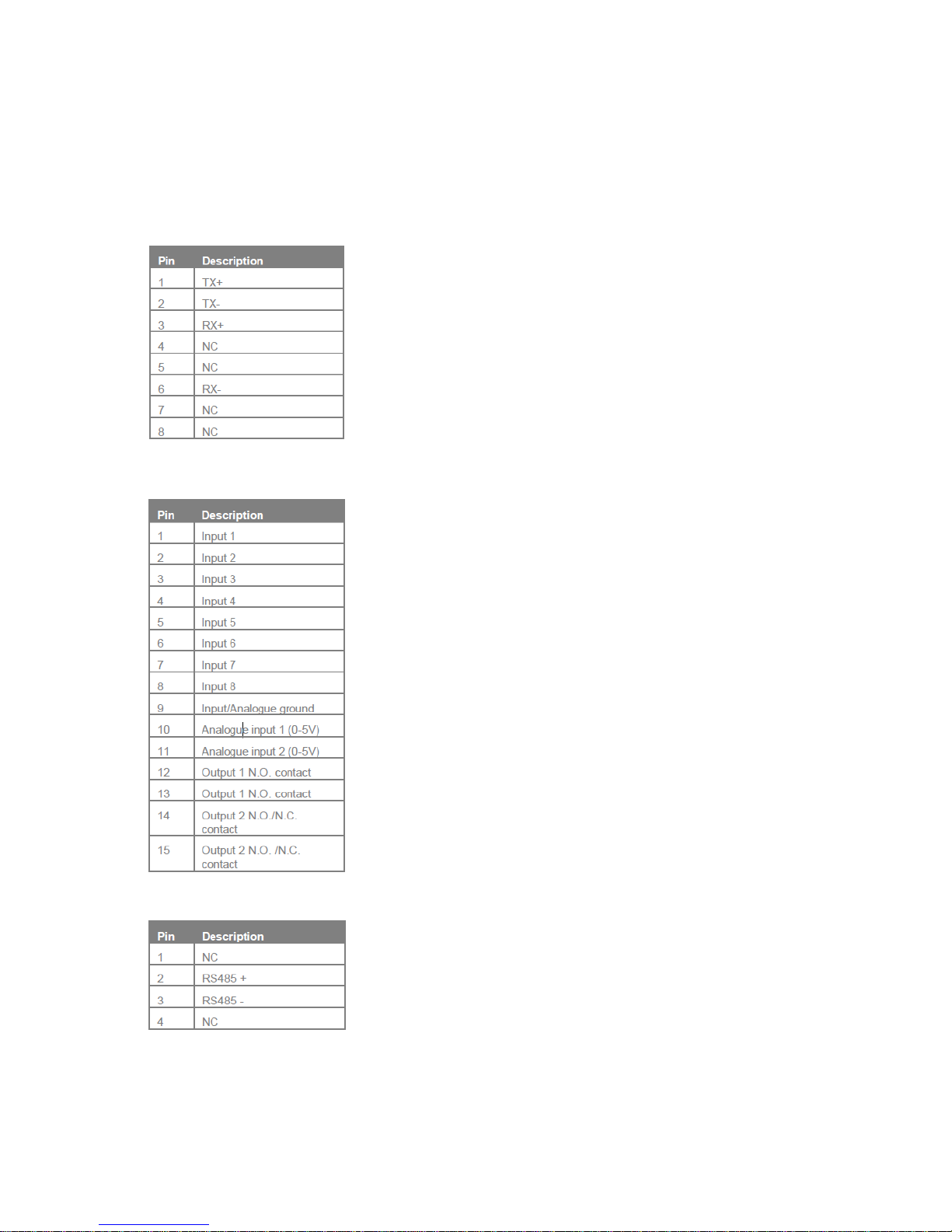
Connections
External connections (Rear panel)
Ethernet Port - 8way RJ45 right-angle socket.
GPIO port - 15way ‘D’ type right-angle socket.
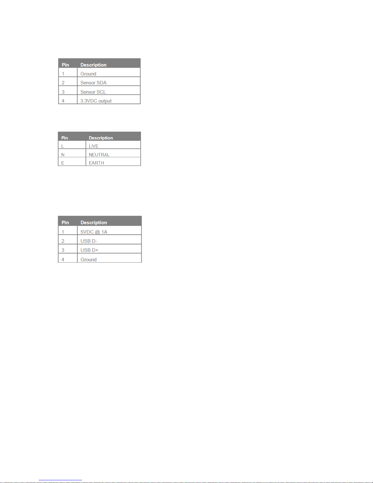
MODBUS port - 2x 4way RJ11 right-angle socket.
Page 12
DOC32 Page 12 of 41 Issue 2 30 NOV 17
Temperature sensor and humidity sensor port - 4way RJ11 right-angle socket.
Mains outlets - 12x C14 IEC outlets.
External connections (Front panel)
USB port - 1x USB type ‘A’ socket.
Page 13
DOC32 Page 13 of 41 Issue 2 30 NOV 17
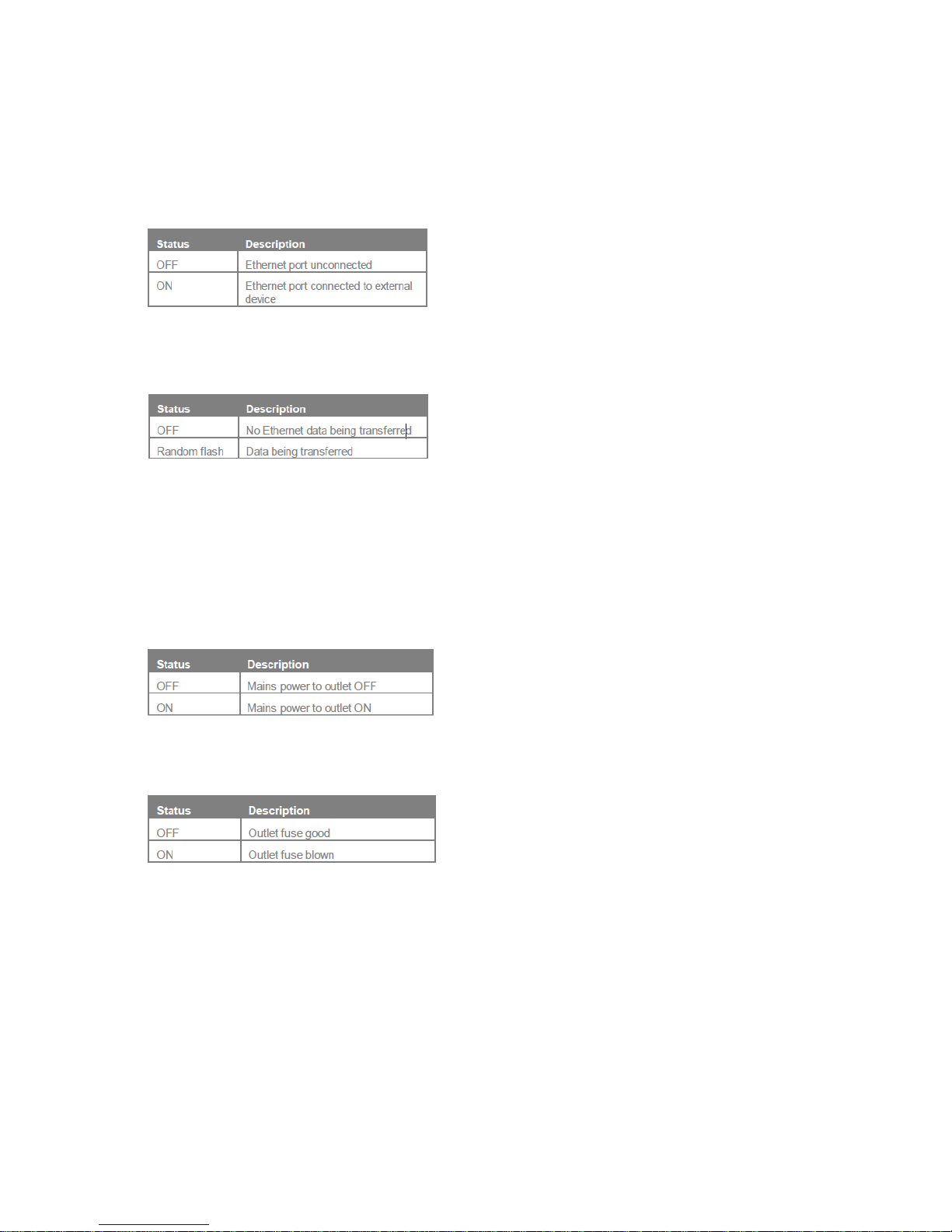
5.0 Indication
External optical indication (rear panel)
Ethernet connection indicator - GREEN L.E.D indicator, mounted on Ethernet port.
Ethernet data indicator - YELLOW L.E.D indicator, mounted on Ethernet port.
External optical indication (front panel)
Front panel mounted switch with integral indicator. Green light is lit when switch is on and
mains applied.
Outlet power indicator - 12x GREEN 3mmD L.E.D indicator, located next to fuse.
Fuse blown indicator - 12x RED 3mmD L.E.D indicator, located next to fuse.
Page 14

DOC32 Page 14 of 41 Issue 2 30 NOV 17
This page is intentionally blank
Page 15

DOC32 Page 15 of 41 Issue 2 30 NOV 17
6.0 Characteristics
AC Characteristics
Mains input 115/230VAC 50-60Hz
Mains input protection Transient suppression (LIVE - NEUTRAL)
Mains power consumption 15W
Maximum load 16A
DC Characteristics
USB Supply output 5VDC @ 1A max.
USB Supply protection 1A Current limit
Ethernet port
Compatibility IEEE 802.3 10/100/1000Base-T (Auto-negotiated to
10 or 100Mb)
Protocols TCP/IP, HTTP, SNMP, XML, DHCP, SMTP, Telnet
MODBUS port
Compatibility RS485 115.2kbps, 8 data bits, no parity, 1 stop bit
Protocol MODBUS RTU
Digital temperature sensor [x8]
Temperature range 0 to +125 °C
Accuracy (Temperature Error) 0°C to +85°C = ±0.5 °C nominal
85°C to +125°C = ±1.0 °C nominal
Resolution +0.0625 °C
Sensor supply voltage 3.3VDC
Sensor interface I2C 3.3V [TTL/CMOS] logic
Humidity sensor [x1]
Humidity range 0-100% Relative humidity
Response Time 8 Seconds in slow moving air @ 25ºC
Stability < 0.5% RH per year
Accuracy ± 2.0% RH, 0-100% RH non-condensing @ 25ºC
Non-linearity < 1% RH Typical
Repeatability ± 0.1% RH
Resolution 0.04 %RH
Temperature range 0 to +125ºC (32 to +254.9°F)
Response Time 5 to 30 seconds
Accuracy ±0.4 °C nominal
Repeatability ± 0.1 °C
Resolution 0.01 °C
Sensor supply voltage 3.3VDC
Sensor interface I2C 3.3V [TTL/CMOS] logic
Page 16

DOC32 Page 16 of 41 Issue 2 30 NOV 17
GPIO inputs
Contact type Voltage free normally open or closed
Contact resistance 2Kohm max.
Contact de-bounce time 50mS
GPIO analogue inputs
Analogue input voltage 0-5V (6V max.) 1023 bits @ 15.244mV per bit
Analogue measurement period 100mS
GPIO control output 1
Output type Voltage free Solid State Relay (SSR)
Output capability 48VDC @ 1000mA max.
GPIO control output 2
Output type Voltage free Mechanical Relay (SPDT)
Output capability 48VDC @ 1000mA max.
General timings
Temperature & humidity measurement rate 1000mS default (software programmable)
General parameters
Login name & password ‘admin’ default (HTML programmable)
Page 17
DOC32 Page 17 of 41 Issue 2 30 NOV 17
Appendix A. Web server HTML page description
Web server HTML page description
The iMDU HTTP web server service provides a set of HTML pages that can be viewed
within any HTML compatible web browser [ie. Internet Explorer, Firefox, Google Chrome
etc.].
Logging into the web server
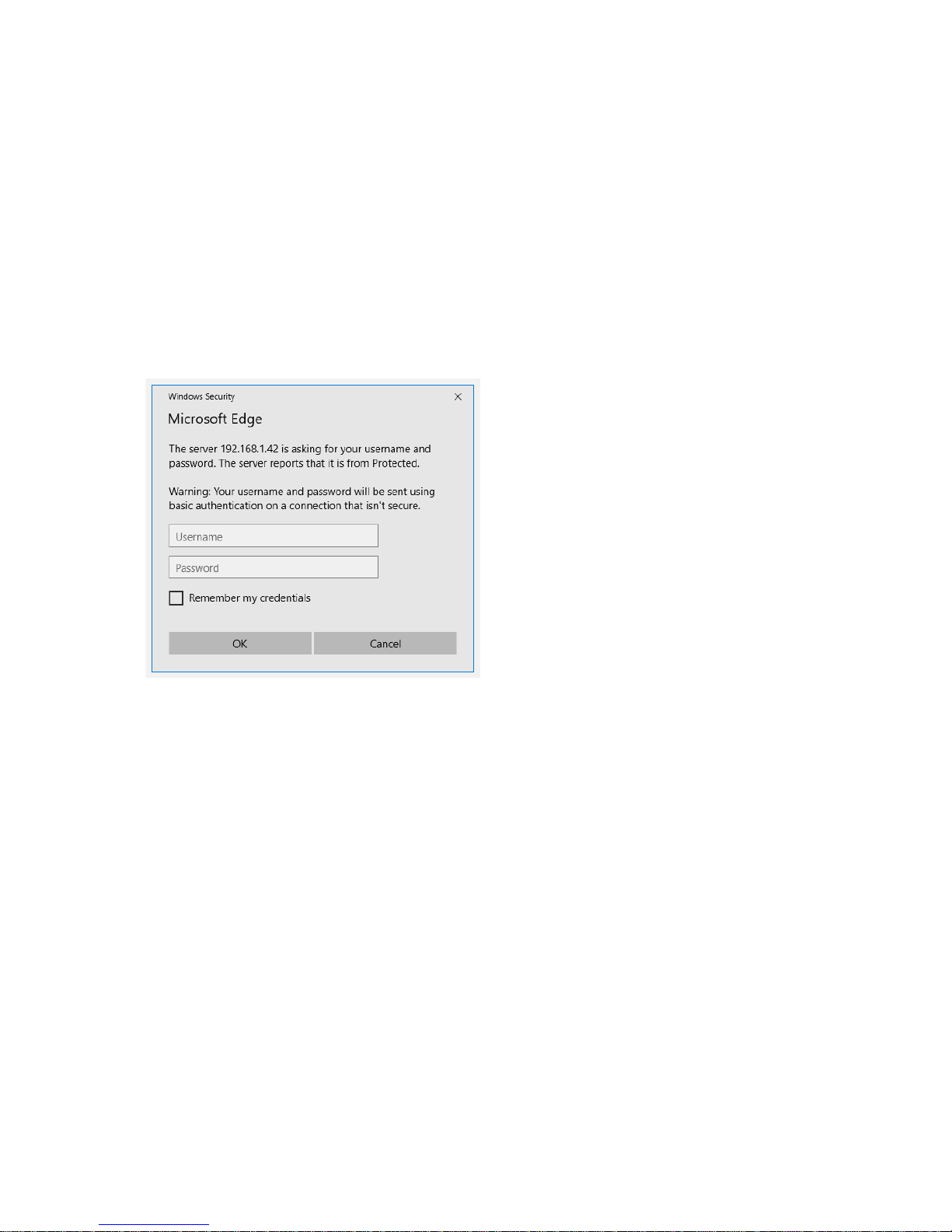
The HTTP service provides Domain Name Service [DNS] resolution so that the iMDU IP
address does not need to be known, entering ‘iMDUSNMP’ into the browsers URL bar will
contact the web server and initiate the authentication process to allow entry into the iMDU
system. The following authentication screen will be displayed:
At this point the operator may enter the system as a User, Administrator or Factory operator.
The default User name and Password for the default administrator account is ‘Admin’ and
the default User name and Password for the factory account is ‘factory’, both are case
sensitive. New accounts may be configured under the ‘Configuration’ tab settings, see later
in this appendix.
User account
A User account prevents access to the all configuration options and most other operations
that could compromise iMDU SNMP operation.
Administrator account
An Administrator account allows the operator to re-configure any aspect of the iMDU
configuration. This configuration includes re-naming of the iMDU customer name, location,
outlet equipment names and changes to default parameters. The Administrator also has
access to buttons that allow the iMDU to turn individual outlets ON/OFF and reset currently
stored energy levels etc.
Page 18
DOC32 Page 18 of 41 Issue 2 30 NOV 17
Factory account
As the Administrator account but allows access to the config.htm page
Overview page
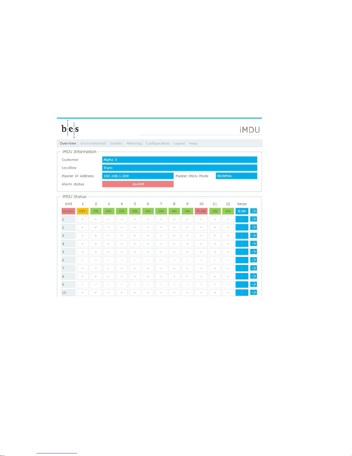
After successful authentication the operator is presented with the initial Overview page which
provides an overview of all master and slave iMDU units. The following screen shot shows a
master only unit with an alarm condition:
The iMDU Information provides an overview of the customer and location to which the iMDU
belongs, its IP address, the mode of operation (NORMAL, MASTER or SLAVE) and the
alarm status.
Below this an overview of the master and connected slave units outlet status and meter
current. Clicking on the arrow next to the status line takes the user to the Outlets page for
this particular unit.
Page 19
DOC32 Page 19 of 41 Issue 2 30 NOV 17
Environmental page
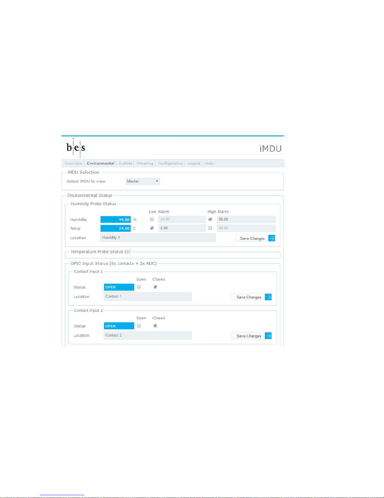
Clicking on the Environmental button the operator is presented with the environmental
status page for the currently selected master or slave which contains details of any humidity
probe or temperature probes connected to the unit, the eight [8] contact inputs, the two [2]
Analogue to Digital Converter (ADC) levels and the two [2] General Purpose Outputs (GPO)
contact outputs.
The following screen shot shows the top of the page with a humidity probe connected and
contacts 1&2 OPEN:
The humidity probe status box provides the temperature and humidity output from any
connected humidity probe along with location name and check boxes and threshold levels to
configure alarms against these parameters. Please see later topic for alarm setup.
The temperature probe status box(s) provide the temperature output from up to eight
temperature probes along with location name and check boxes and threshold levels to
configure alarms against these parameters. Please see later topic for alarm setup.
The contact status boxes provide the status (OPEN or CLOSED) of the contact inputs along
with location name and check boxes to configure alarms. Please see later topic for alarm
setup.
Page 20
DOC32 Page 20 of 41 Issue 2 30 NOV 17
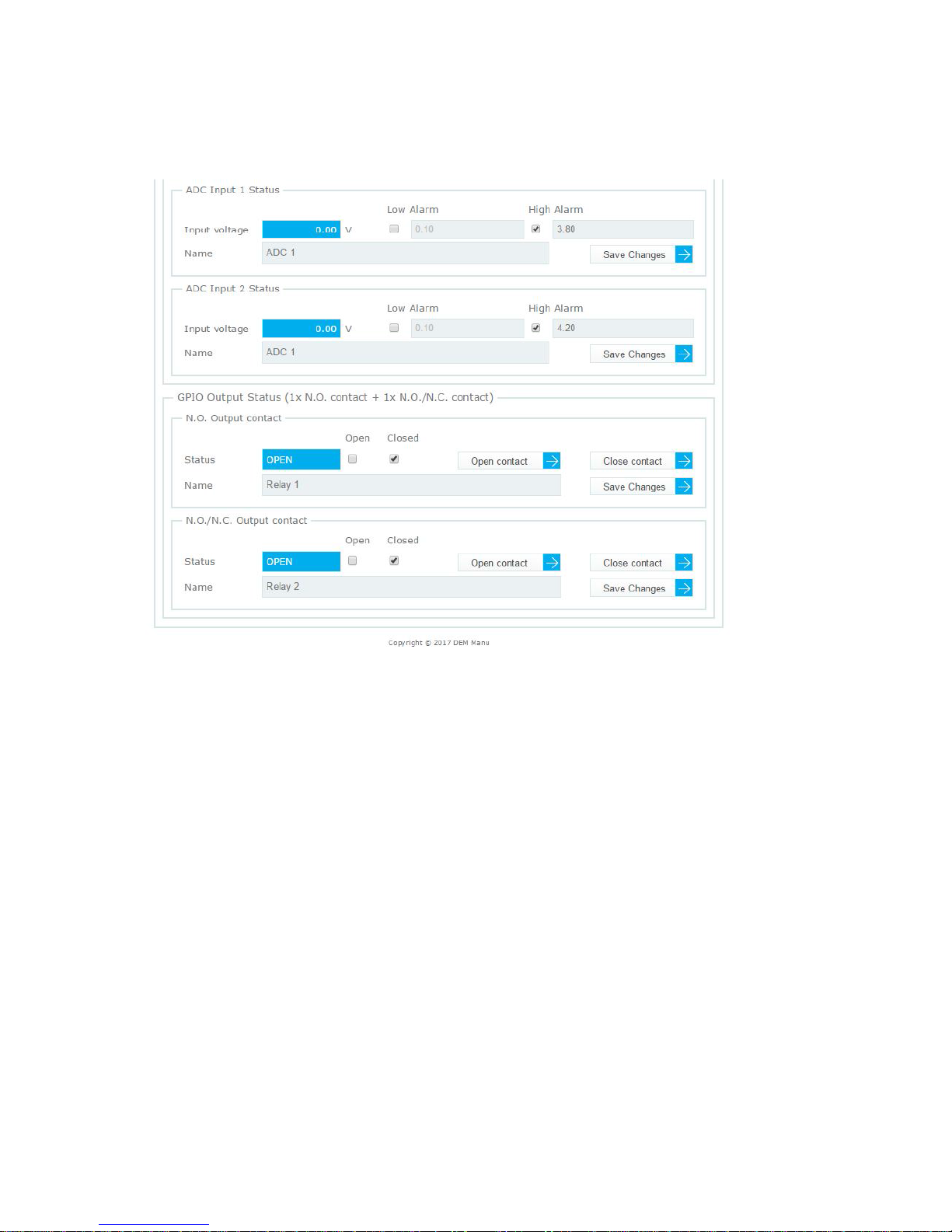
The following screen shot shows the bottom of the page showing the two ADC channels and
the two GPO outputs:
The ADC Input status boxes show the input voltage measured from the ADC a name and
check boxes and threshold levels to configure alarms against these parameters. Please see
later topic for alarm setup.
The GPO Output status boxes provide the status (OPEN or CLOSED) of the contact outputs
along with name and check boxes to configure alarms. Please see later topic for alarm
setup.
Page 21
DOC32 Page 21 of 41 Issue 2 30 NOV 17
Outlets page
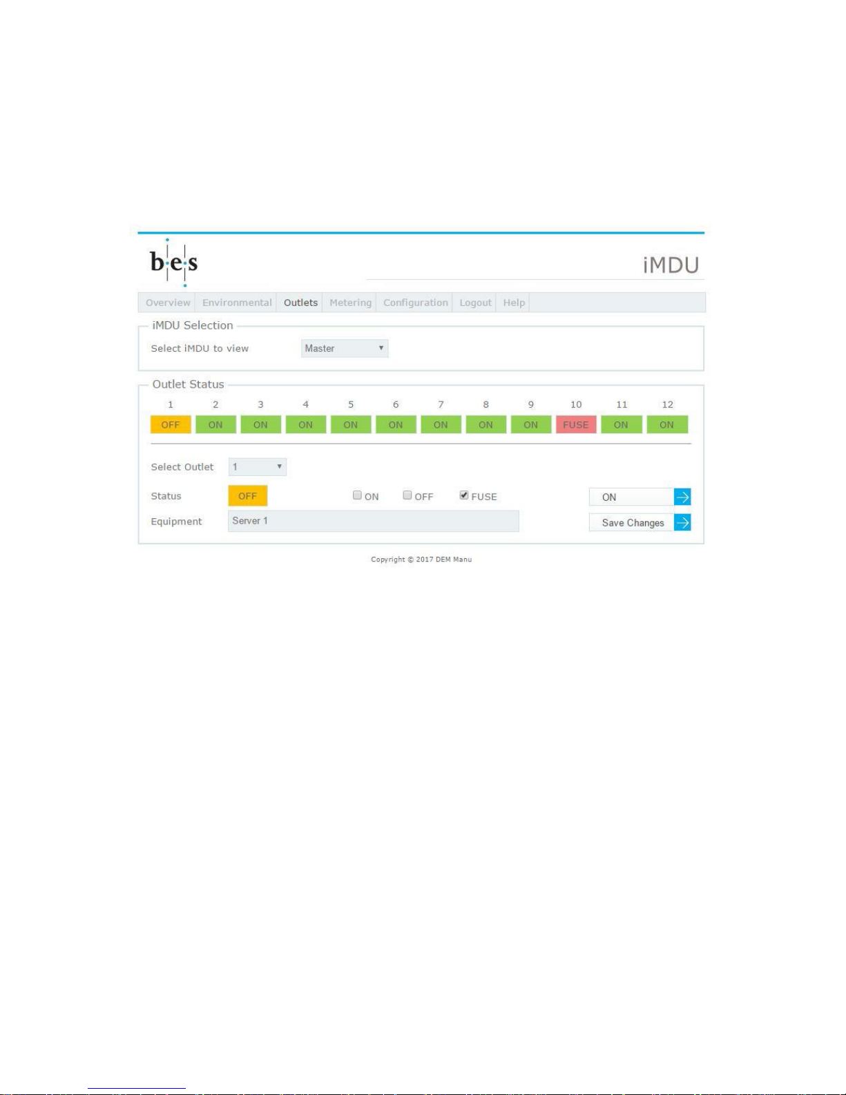
Clicking on the Outlets button the operator is presented with the outlets status page for the
currently selected master or slave which displays status of the twelve [12] outlets on the
system. The following screen shot shows the Master selected with outlet 1 OFF and a fuse
blown alert on outlet 10:
Each outlet has a status of ON, OFF or FUSE which are depicted as ORANGE, GREEN or
RED respectively to allow ‘at a glance’ determination of status.
An outlet can be selected using the drop-down menu and its status box provide the status
(ON, OFF or FUSE) of the outlet along with equipment name and check boxes to configure
alarms. Please see later topic for alarm setup.
A button is provided to switch the outlet ON or OFF, depending on its current status, unless
a FUSE indication is shown.
Page 22
DOC32 Page 22 of 41 Issue 2 30 NOV 17
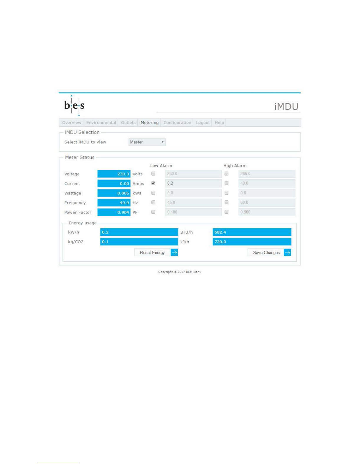
Metering page
Clicking on the Metering button the operator is presented with the metering page for the
currently selected master or slave which contains measurements from the on-board meter.
The following screen shot shows the unit connected to a 230VAC supply and no load:
The iMDU RMS volts, amps, kW’s, frequency and power factor are shown along with check
boxes and threshold levels to configure alarms against these parameters. Please see later
topic for alarm setup.
The Energy usage box provides the total energy usage on this iMDU, including relevant
conversions such as kgCO2.
Buttons on this page allow the alarm thresholds to be saved and the energy consumption to
be reset if required.
Page 23
DOC32 Page 23 of 41 Issue 2 30 NOV 17
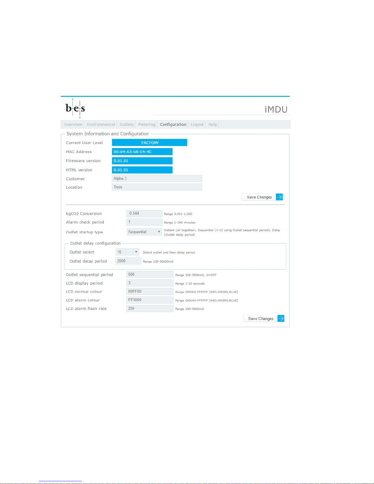
Configuration page
Clicking on the Configuration button the operator is presented with the Configuration page
which contains configuration details for the unit. The following screen shot shows the System
Information and Configuration box at the top of the page:
The top half of the System Information and Configuration box shows the currently logged in
operator level, USER, ADMINISTRATOR or FACTORY, current firmware version, the HTML
page version, customer name and location.
The bottom half of the System Information and Configuration box shows all the parameters
that can be configured within the system.
Outlet startup type allows Instant (all outlets turn ON together), Sequential (outlets turn ON
from 1 to 12 with an Outlet sequential period between each) or Delay (outlets turn ON from 1
to 12 with an individual delay for each outlet, setup in the Outlet delay configuration box) to
be configured.
If an LCD panel is connected the LCD functions define its operation.
Page 24
DOC32 Page 24 of 41 Issue 2 30 NOV 17
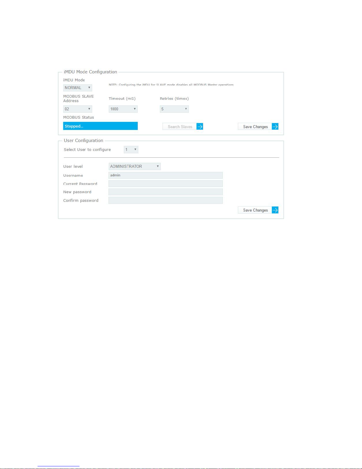
The second section of the page contains the iMDU Mode Configuration, USER Configuration
and Network Configuration boxes:
The iMDU Mode Configuration box allows the iMDU mode to be configured (NORMAL-No
MODBUS support, MASTER-MODBUS Slaves are queried and data collected and SLAVE-
External master collects data from this iMDU using the configured slave address).
When configured for MASTER the Timeout (time to wait for a slave to respond) and Retries
(Number of times the master retries a query) are configurable.
When configured for SLAVE the MODBUS Slave Address must be configured to an
exclusive address on the MODBUS network. The MODBUS Status box provides real-time
information about MASTER mode queries or SLAVE mode requests being made on the
MODBUS network.
The User Configuration box allows a maximum of 20 users to be configured with one of 3
different user levels. USER level allows access to all pages, but 'Save Changes' buttons are
disabled. ADMINISTRATOR level allows access to all pages and 'Save Changes' are
enabled as well as upgrade functions. FACTORY level provides access to all pages and
buttons as well as advanced configurations on the config.htm page.
Page 25
DOC32 Page 25 of 41 Issue 2 30 NOV 17
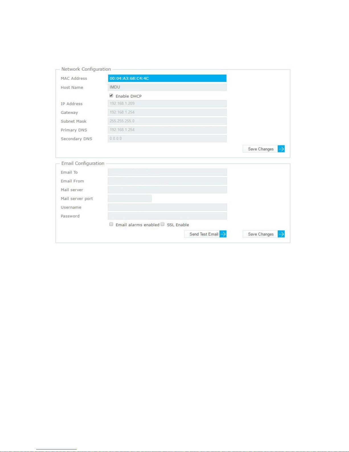
The third section of the page contains the Network Configuration and Email Configuration
boxes:
The Network Configuration box allows the host name and DHCP configuration to be
configured. When DHCP is disabled a static IP address, gateway and DNS addresses may
be configured. Changes can be made to the fields by de-selecting the 'Enable DHCP'
checkbox, updating the fields and clicking the 'Save Changes' button.
The Email Configuration box allows the email address and mail server to be configured for
email alarms. Enter the destination email, from email and the email server information and
click 'Save Changes' then 'Send Test Email' button to test the configuration. The SSL
checkbox allows SSL to be used for email when set.
Page 26
DOC32 Page 26 of 41 Issue 2 30 NOV 17
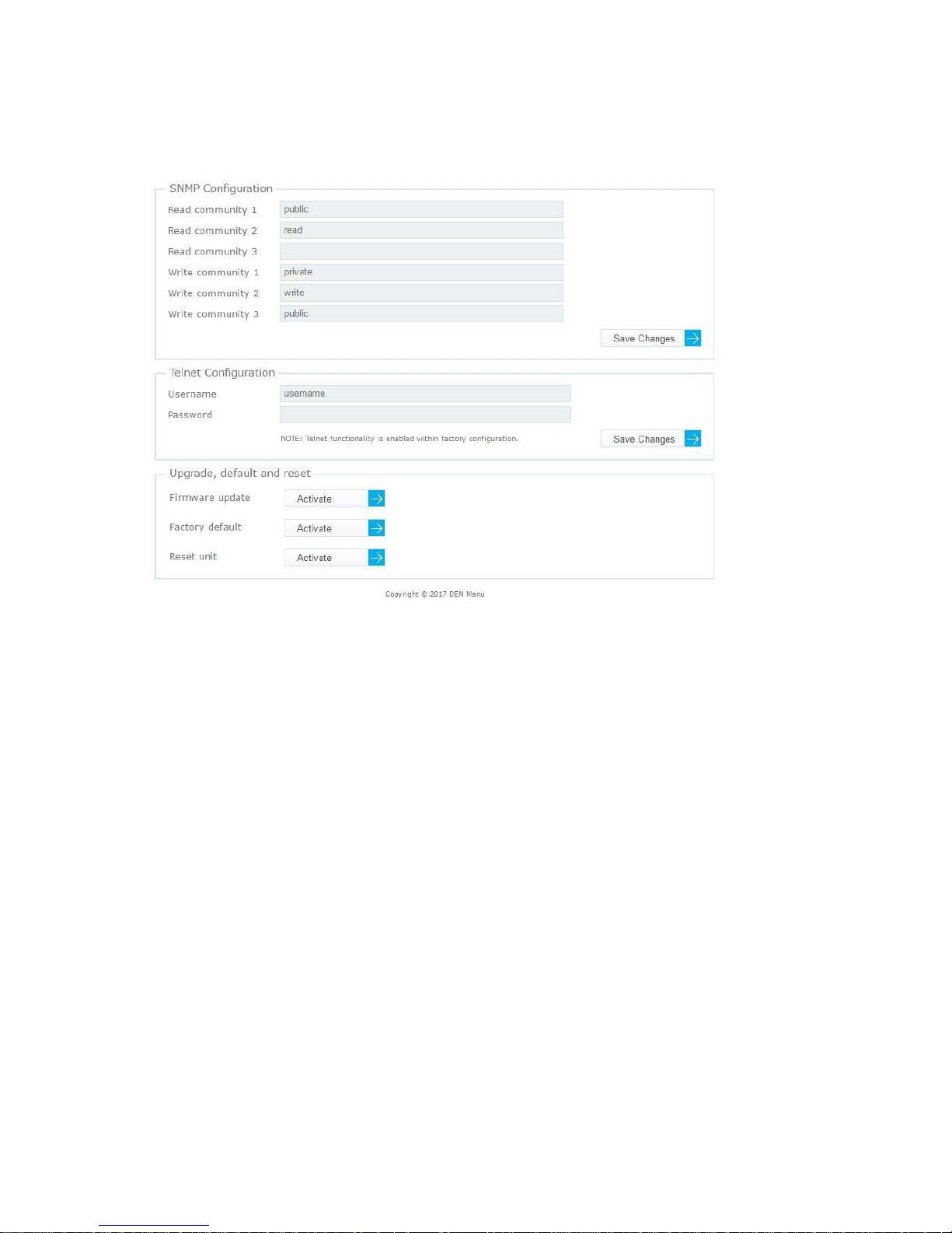
The fourth section of the page contains the SNMP Configuration, Telnet Configuration and
Upgrade, default and reset boxes:
The SNMP Configuration box allows the SNMP Read and Write communities to configured.
Enter up to 3 communities for read and write or leave blank if unused and update by clicking
'Save Changes'.
The Telnet Configuration box allows the Telnet authentication username and password to be
configured. Enter username and password and update by clicking 'Save Changes'. Note that
the Telnet functionality can only be enabled from the Advanced Configuration page
config.htm.
The Upgrade, default and reset box contains the followign functions:
The iMDU firmware can be upgraded by clicking on the Activate button and following the
prompts. CAUTION: The iMDU may be rendered inoperative if firmware update is
unsuccessful.
The iMDU configuration can be reset to the factory defaults by clicking the Activate button.
CAUTION: Current configuration data [name, alarm values etc.] will be lost.
The iMDU unit can be reset by clicking the Activate button.
Page 27

DOC32 Page 27 of 41 Issue 2 30 NOV 17
Alarm setup and generation
Individual pages allow various low, high and event alarms to be configured.
To setup a low threshold alarm click on the Low Alarm checkbox and enter a threshold level
at which an alarm should be generated if the reported value drops below i.e. for a
temperature alarm enter 5.00 if you want an alarm to be generated if the temperature drops
below 5.00C. To setup a high threshold alarm click on the High Alarm checkbox and enter a
threshold level at which an alarm should be generated if the reported value rises above i.e.
for a temperature alarmenter 40.00 if you want an alarm to be generated if the temperature
rises above 40.00C.
Click on the 'Save Changes' button to update the alarm setting. Note: An alarm comparison
is immediately undertaken on configuring a new alarm.
The normal alarm check period of 1 to 240 minutes can be configured on the Configuration
page. On every alarm check period timeout all configured alarm thresholds are compared
with the currently report value and if found to be above or below the threshold an SNMP trap
generated, see SNMP Trap Host Setup in Appendix B, and if the Email alarms enabled
checkbox is selected on the Configuration page and alarm email will also be generated to
the configured email address.
Page 28
DOC32 Page 28 of 41 Issue 2 30 NOV 17
Advanced Configuration page (hidden)
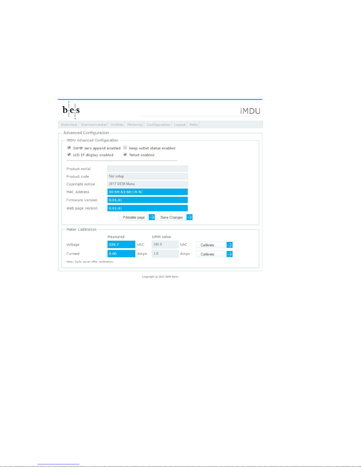
On entering the IP address followed by /config.htm in the top bar the operator, must be a
factory level user, is presented with the Advanced Configuration page which contains
advanced configuration details. The following screen shot shows the iMDU Advanced
Configuration and Meter Calibration boxes:
The iMDU Advanced Configuration box allows a number of factory configurable settings to
be changed, induding: System serial number, page copyright notice and product code and a
printable page can also be generated containing this information along with the system MAC
address.
The Meter Calibration box allows the meter to be calibrated. To calibrate voltage measure
the mains voltage [RMS] at the feed input, enter the value in the DMM field and click on
Calibrate. To calibrate current a RMS ammeter must be placed in series with an outlet and
load device eg. heater. Enter the amps value in the DMM field and click on Calibrate.
Logout button
Clicking on the Logout button the operator is presented with a blank page.
Page 29
DOC32 Page 29 of 41 Issue 2 30 NOV 17
Appendix B. SNMP trap setup and register description
Overview
The iMDU supports multiple SNMP registers which can be accessed through its MIB file
definition [IMDU_Vxxx.mib] by any SNMP manager. The product supports all standard
SNMP operations such as GET, SET, GET NEXT, GET SUBTREE, GET BULK and WALK
along with table viewing for some sets of registers and global registers.
The product is also capable of generating SNMP traps when previously setup alarm
thresholds or alarm conditions are encountered.
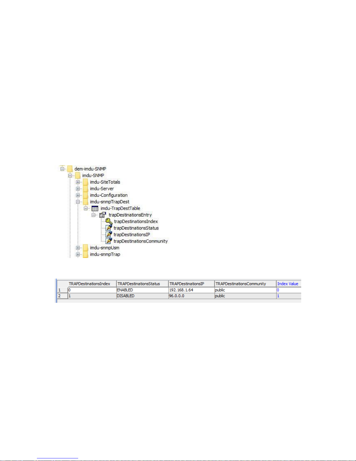
SNMP trap host setup
The iMDU supports two SNMP host IP addresses allowing two different host systems to be
sent trap alarm information. The host destination enable status, destination IP address and
SNMP community string are setup through a table view of the imdu-TrapDestTable:
Which when viewed as a table will look like this:
The destination IP address should be set to the IP of the host that is to receive the trap
notifications and the trap destination status set to ‘1’ for ENABLED. The SNMP trap
community can also be changed if required. Once configured any alarms generated by the
system will be sent as traps every <AlarmPeriod> minutes.
Page 30

DOC32 Page 30 of 41 Issue 2 30 NOV 17
This page is intentionally blank
Page 31
DOC32 Page 31 of 41 Issue 2 30 NOV 17
SNMP register definitions
The iMDU register set can be broken into two [2] functional categories, imdu-SNMP and
slave-Global.
Please refer to Appendix A – Web server HTML web page description for more
information about the individual values available as registers.
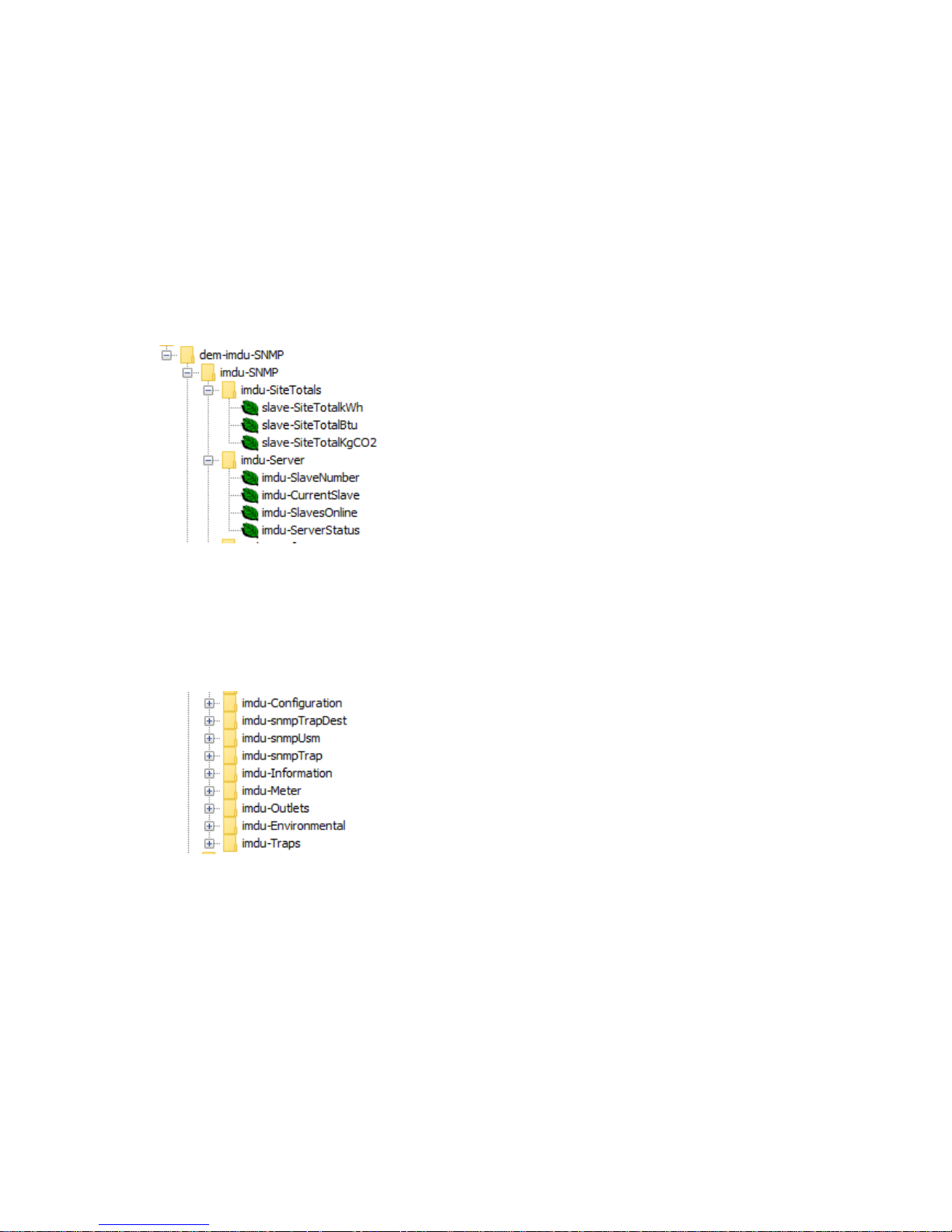
imdu-SNMP Site totals and Server status registers
The imdu-SiteTotals and imdu-Server branches allow the iMDU Slave totals to be read and
the server status to be read. The following MIB tree shows the registers available:
imdu-SNMP Master configuration and information registers
The remaining imdu-SNMP branches contain registers that allow the master iMDU status
registers to be read (Meter, Outlets and Environmental), allow the Master iMDU to be
configured and trap thresholds to be setup. The following MIB tree shows the branches
available:
Page 32
DOC32 Page 32 of 41 Issue 2 30 NOV 17
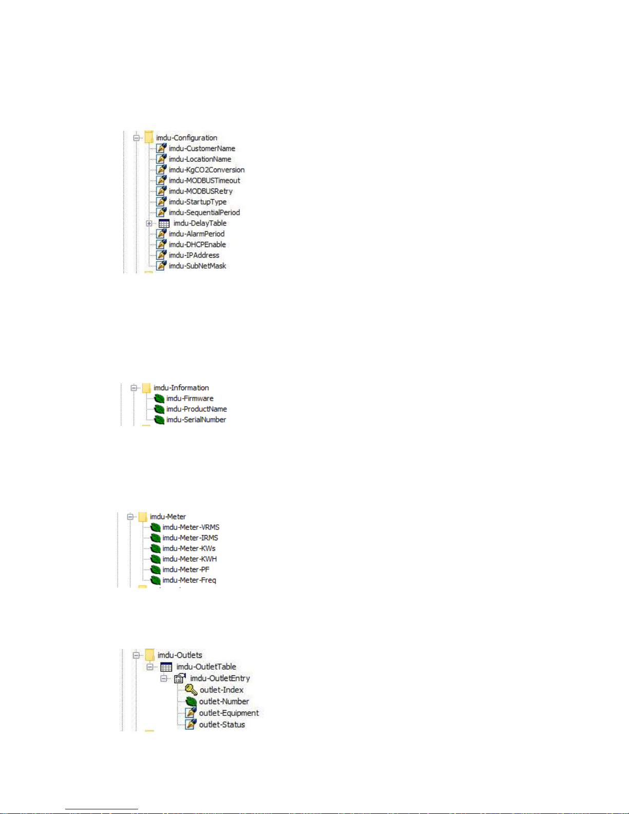
imdu-Configuration branch
The imdu-Configuration branch contains relevant configuration information for the Master
iMDU as follows:
Registers to display Master iMDU customer and iMDU location name, CO2 conversion
factor, MODBUS interface setup, outlet start-up configuration and network settings are
accessible with those displaying a pen nib also being configurable.
imdu-Information branch
The imdu-Information branch contains relevant information for the Master iMDU as follows:
imdu-ProductName and imdu-SerialNumber are set at factory.
imdu-Meter branch
The imdu-Meter branch contains meter measurements for the Master iMDU as follows:
imdu-Outlets branch
The imdu-Outlets branch contains outlet status for the Master iMDU as follows:
Page 33
DOC32 Page 33 of 41 Issue 2 30 NOV 17
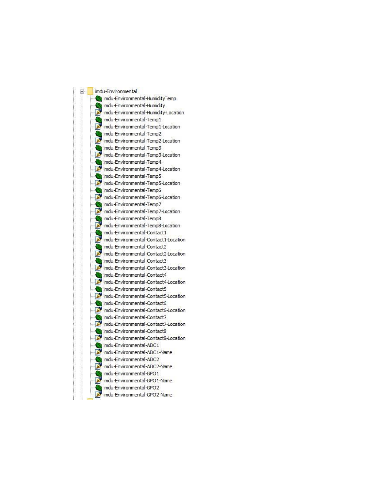
imdu-Environmental branch
The imdu-Environmental branch contains humidity probe, temperature probe, contact input,
ADC input and GPO output measurements and status for the Master iMDU as follows:
Page 34
DOC32 Page 34 of 41 Issue 2 30 NOV 17
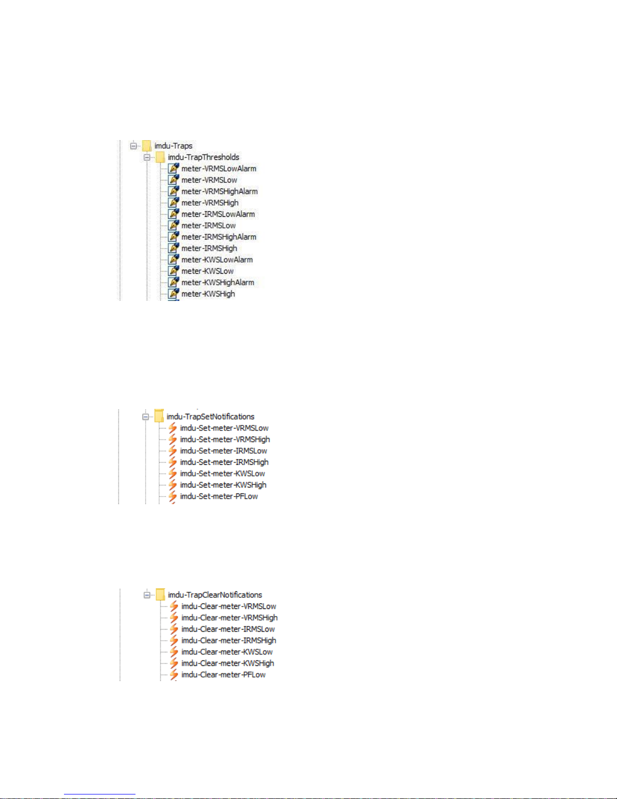
imdu-Traps - imdu-TrapThresholds branch
The imdu-TrapThresholds branch allows the Master iMDU alarm thresholds and conditions
to be configured. The first few can be seen as follows:
Please refer to Appendix A – Web server HTML web page description for more
information about the individual values available as registers.
imdu-TrapSetNotifications branch
The imdu-TrapSetNotifications branch contains the trap SET (when an alarm is activated)
definitions for all Master and Slave traps, a small sample of which are as follows:
imdu-TrapClearNotifications branch
The imdu-TrapClearNotifications branch contains the trap CLEAR (when an alarm is
deactivated) definitions for all Master and Slave traps, a small sample of which are as
follows:
Page 35
DOC32 Page 35 of 41 Issue 2 30 NOV 17
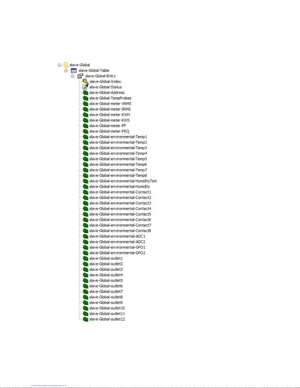
Slave-Global branch
The Slave-Global branch contains tabled registers that allow the Master and all Slave
iMDU’s in the installation to be viewed as follows:
Please refer to Appendix A – Web server HTML web page description for more
information about the individual values available as registers.
Page 36
DOC32 Page 36 of 41 Issue 2 30 NOV 17
SNMP V3 Setup
The iMDU also support SNMP V3 which supports authenticated and encrypted SNMP
operations such as GET, SET, GET NEXT, GET SUBTREE, GET BULK and WALK along
with table viewing for some sets of registers and global registers.
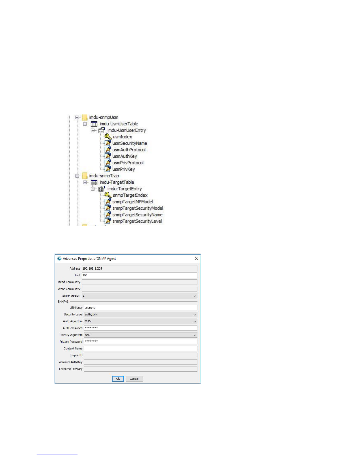
The SNMP manager must be pre-configured with username, authentication protocol,
authentication password, privacy protocol and privacy password before SNMP V3 operations
cantake place. The following branches show the tables that allow these parameters to be
configured:
Before SNMP V3 operations can be undertaken the SNMP manager must be configured. An
example iReasoning setup is as follows:
The default credentials for ‘userone’ are MD5 auth algorithm with password ‘authpass’ and
AESprivacy algorithm with password ‘privpass’. Context Name MUST be left blank.
Page 37
DOC32 Page 37 of 41 Issue 2 30 NOV 17
Appendix C. Telnet command line interface description
Telnet server
The iMDU supports a configuration selectable Telnet command line interface that allows a
user to control/monitor system settings and measurements.
Logging into the Telnet server
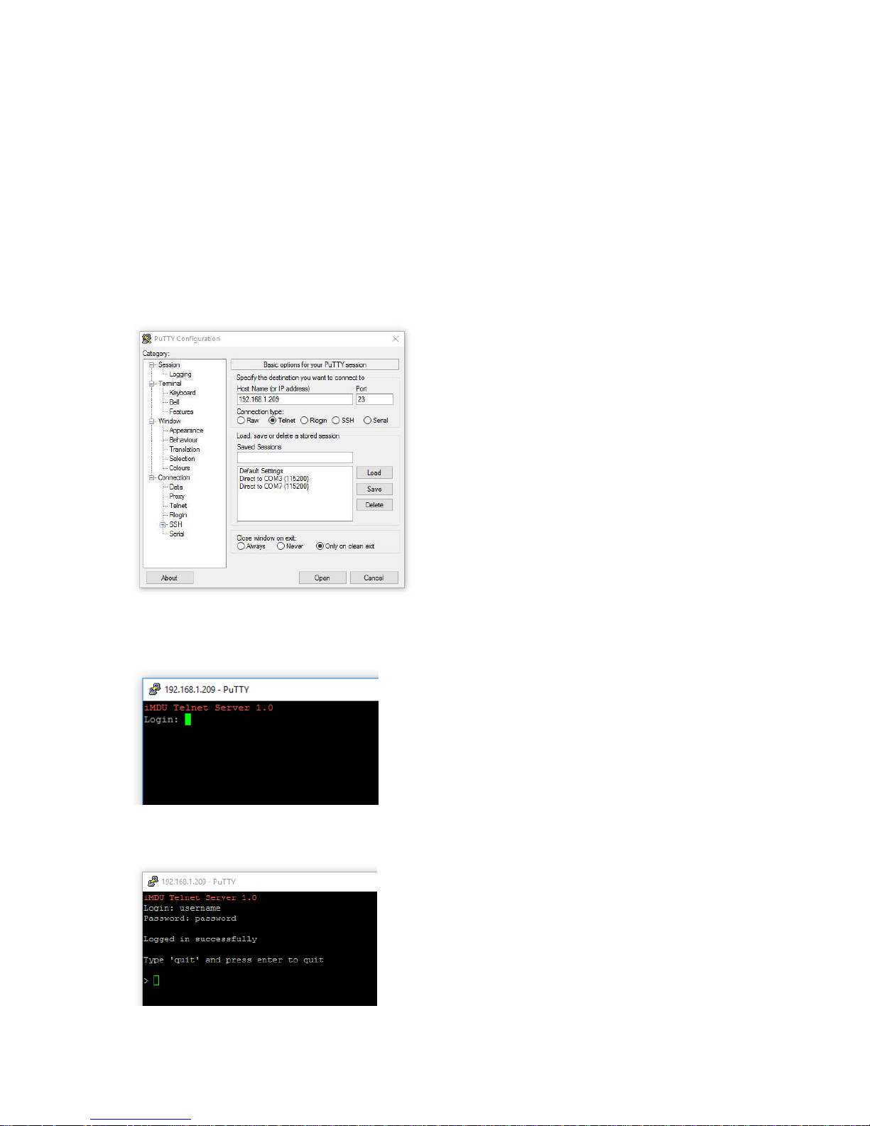
The Telnet server can be logged into using any Telnet compatible application. For clarity the
following description uses the Putty application
(http://www.chiark.greenend.org.uk/~sgtatham/putty/latest.html) as the client as it is
available as a free download. After starting the application you will be presented with
following setup screen:
Select the ‘Telnet’ radio button, enter the iMDU IP address into the ‘Host Name’ box and
click‘Open’. If a connection is made you will be presented with the following screen:
Enter the default user name ‘username’ and password ‘password’ and the following screen
will be displayed:
Page 38

DOC32 Page 38 of 41 Issue 2 30 NOV 17
Telnet server commands
The Telnet server supports a number of commands that allow the slave iMDU to be
selected, outlets read and set and metering/environmental measurements to be read.
Read outlet command
The Read outlet command allows the status of an outlet to be returned, the format being:
read outlet xx
Where xx is the outlet number 01-12, replies with:
Outlet xx: ddd
Where ddd is ON if the outlet is on, OFF if the outlet is off or FUSE BLOWN if the outlets
fuse has opened.
Set outlet command
The Set outlet command allows an outlet to be switched on/off instantly or with a delay and
be cycled off/on with a delay, the format being:
set outlet xx dddd
Where xx is the outlet number 01-12 and dddd is as follows:
on instant
Turns the outlet on instantly.
off instant
Turns the outlet off instantly.
on delay
Turns the outlet on after the delay period setup on the configuration page for that particular
outlet.
off delay
Turns the outlet off after the delay period setup on the configuration page for that particular
outlet.
Cycle
Turns the outlet off and then on again using the delay setup on the configuration page for
that particular outlet.
Read meter voltage command
The Read meter voltage command returns the current voltage measured by the meter, the
format being:
read volts
Replies with:
Meter volts: vvv.vVAC
Where vvv.v is the current AC voltage.
Page 39

DOC32 Page 39 of 41 Issue 2 30 NOV 17
Read meter current command
The Read meter current command returns the current amps measured by the meter, the
format being:
read current
Replies with:
Meter current: aa.aaA
Where aa.aa is the current AC amperage.
Read meter power command
The Read meter power command returns the current wattage in kWs measured by the
meter, the format being:
read power
Replies with:
Meter power: ww.wwwwkWs
Where ww.wwww is the current power in kWs.
Read meter frequency command
The Read meter frequency command returns the current mains frequency measured by the
meter, the format being:
read freq
Replies with:
Meter frequency: ff.fHz
Where ff.f is the current frequency in Hz.
Read meter power factor command
The Read meter power factor command returns the current PF measured by the meter, the
format being:
read pf
Replies with:
Meter PF: p.ppp
Where p.ppp is the current power factor.
Read meter energy command
The Read meter energy command returns the current energy in kWhs measured by the
meter, the format being:
read energy
Replies with:
Meter energy: eeeee.ekWh
Page 40

DOC32 Page 40 of 41 Issue 2 30 NOV 17
Where eeeee.e is the current power in kWhs.
Read humidity command
The Read humidity command returns the current humidity and temperature measured by the
humidity probe, the format being:
read humidity
Replies with:
Humidity: hh.hh% Temp: tt.ttC
Where hh.hh is the humidity in % and tt.tt is the temperature in celsius.
Read temperature probe command
The Read temperature probe command returns the current temperature measured by the
selected temperature probe, the format being:
read probe xx
Where xx is the probe to read 01-08, replies with:
Temperature probe xx: tt.ttC
Where tt.tt is the temperature in celsius.
Read contact command
The Read contact command allows the status of a contact to be returned, the format being:
read contact xx
Where xx is the contact number 01-08, replies with:
Contact xx: ddd
Where ddd is OPEN if the contact is open, CLOSED if the contact is closed.
Page 41

DOC32 Page 41 of 41 Issue 2 30 NOV 17
Read ADC level command
The Read ADC level command returns the current voltage measured on the selected ADC
channel, the format being:
read adc xx
Where xx is the probe to read 01-02, replies with:
ADC xx: v.vvV
Where v.vv is the voltage 0.00-5.00V.
Set gpo command
The Set gpo command allows a gpo contact to be opened or closed, the format being:
set gpo xx dddd
Where xx is the gpo number 01-02 and dddd is as follows:
Close
Closes the output contact.
open
Opens the output contact.
Help command
The help command provides a summary of the commands, the format being:
help
And returns the following:
read outlet XX
set outlet XX on/off/cycle instant/delay
read volts
read current
read power
read freq
read pf
read energy
read humidity
read probe YY
read contact YY
read adc ZZ
set gpo ZZ
where XX=01-12, YY=01-07 & ZZ=01-02
Quit command
The Quit command exits the Telnet session, the format being:
quit
 Loading...