

Page 1
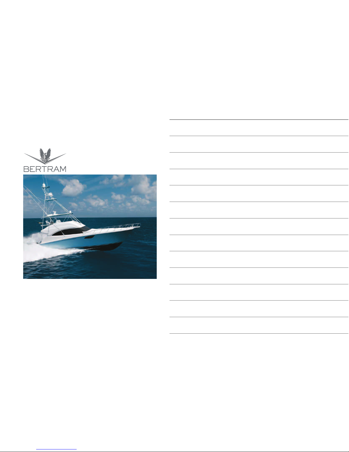
540
OWNER’S MANUAL
Page 2

Studio ti S.r.l.
40026 Imola (BO) - Italy
Via Ercolani, 5c
Tel. +39 (0542) 643513 - 643321
Fax +39 (0542) 643514
This manual has been created by Studio ti in compliance with UNI EN ISO 10240:2004, for BERTRAM.
Any reprinting, either in whole or in part, without prior written approval by BERTRAM is strictly prohibited.
This manual has been issued by BERTRAM a division of:
Legal seat:
Via Irma Bandiera, 62
47841 Cattolica – Rimini – Italy
Tel. +39.05410.839611
Fax +39.05410.839625
Operations headquarters:
3663 N.W. 21st Street, Miami, Florida 33142
(305) 633-8011
Fax (305) 635-1388
www.bertram.com
www.studio-ti.it
Page 3

540
Studio ti 03312 540-04usa
3
RINA S.p.A. (Registro Italiano Navale) assigned the classification of Your
BERTRAM yacht with Certificate, following its supervision of hull
lamination, reinforcement structures, propulsion and auxiliary power
generating machinery, onboard systems.
Specifications
Manufacturer Name BERTRAM
Hull No. 04
Number of People Capacity max. 14
Propulsion type: engine (nr. 2)
Maximum Rated Engine Power 1676 mhp/1232 kW
Dimensions
- Length overall with fore pulpit 57 ft 1 in - 17.40 m
- Length hull (standard ISO 8666) 54 ft 2 in - 18.04 yd
- Length waterline, yacht fully laden 47 ft 8 in - 15.90 yd
- Fore rail extension pulpit 2 ft 11 in - 0.98 yd
- Maximum Beam 16 ft 11 in - 5.64 yd
- Draft under propellers (yacht fully laden) 5 ft - 5 in - 1.65 m
- Max. height (from the keel to the console) 19 ft 4 in - 5.9 m
- Cockpit surface 170 ft² - 17.28 yd
2
Displacements
- Displacement, unladen 64,375 lb - 29.2 ton
- Displacement fully laden 82,853 lb - 37.58 ton
Tank capacities
- Standard fuel tank capacity 1400 US gals - 5300 lt *
- Water tank capacity 225 US gals - 850 lt *
- Black water tank capacity 101 US gals - 382 lt *
- Grey water tank capacity 37 US gals - 140 lt *
* The usable volume of tanks will vary according to the trim and load.
NOTICES
The EC Certificate of product check stating that this pleasure boat has
been approved in accordance with the 94/25/EC Directive, amended by
the 2003/44/EC Directive, and that it conforms to the safety
requirements applicable, is not included inside of the current Owner’s
manual, but it will be delivered separately by BERTRAM and will have
to be stored with this manual.
Page 4

540
Studio ti 03312 540-04usa
4
LIMITED WARRANTY
BERTRAM YACHT, INC. (U.S.A.)
Bertram Yacht, Inc. (Bertram) warrants, subject to the limitations herein,
to the first retail purchaser of this yacht (first owner) provided the First Owner
completes, signs and returns the Bertram Warranty Registration Card to
Bertram at the address below by certified mail, return receipt requested, within
(10) days of the First Owner’s purchase of the yacht, and any properly
registered subsequent owners, that it will repair or replace defects in (a) items
manufactured by Bertram for one (1) year and (b) the yacht’s hull and its
fiberglass structural components for five (5) years. These warranties run from
the date of Delivery. “Delivery” means the date of the actual delivery of the
yacht to the First Owner. Unless prohibited by applicable state law, an action
hereunder shall be barred unless it is commenced with in (1) year from the
date the cause of action accrues, regardless of the time remaining in the
applicable period above.
Bertram’s Obligation. Bertram’s obligation is limited to repairing or replacing,
at its option, any covered items found to be defective at a facility designated
by Bertram. Repaired or replaced items shall be warranted as provided herein
for the remainder of the applicable warranty period. Defective parts or
components that are replaced shall thereupon become the property of
Bertram.
Procedures. Notice of defects occurring under this Limited Warranty must
be given to Bertram within a reasonable time, not to exceed thirty (30) days
after discovery, or the time such defect should reasonably have been
discovered, in writing, at the address below, by certified mail, return receipt
requested. All notices must include the owner’s name, address, phone
number, the hull number, the nature of the defect, the date it was discovered,
the date of purchase, and the name and address of the party from whom
the yacht was purchased. A copy must also be sent to the dealer from whom
the yacht must was purchased.
The owner must thereafter provide all information necessary to allow Bertram
to verify compliance with these requirements. The dealer must obtain
Bertram’s written approval before repairing the yacht and must follow all
applicable Bertram procedures. As to items not covered by this Limited
Warranty, the owner may contact the appropriate manufacturer
representative, to which the dealer will direct the owner on request.
Future Improvements. Bertram reserves the right to improve its design or
materials without any obligation, or incorporate any changes into any
previously manufactured yachts.
Exclusions. This Limited Warranty is NOT applicable to:
a. Damage to a yacht part or component, caused by any alteration, modification,
or repair, or which has been removed from the yacht, unless specifically
authorized in writing by Bertram.
b. Paints; varnishes; gelcoats; anti-fouling products; chrome plated, anodized,
aluminum, or other plated finishes; the color fastness of materials or finishes;
external wood paneling, siding, and trimming; stainless steel, fabrics and canvas
- all of which are subject to the effects of different climates and use (including
cracking and crazing); osmosis blistering if the original gelcoat surface has been
altered in any way - including repair, application of any coating other than marine
antifouling bottom paint, improper surface preparation for paint, or excessive
sanding or sandblasting.
c. Engines, engine parts, controls, accessories, air conditioning systems,
transmissions, electronics (including the installation thereof unless installed by
Bertram), batteries, appliances, propellers, generators, and any equipment not
manufactured by Bertram. Some of these items are warranted by their
manufacturers as stated in the applicable warranties as supplied by their
manufacturers. The owner shall look exclusively to these manufacturers for
any and all such warranty claims.
d. Yachts which have been used for or subjected to: commercial or charter
service; careless operation, grounding, collision, hurricane conditions or other
extreme forces of nature; military or paramilitary operations; racing, towing,
improper storage, service or maintenance; negligent operation; lack of
maintenance; improper use; use in violation of instructions provided by
Bertram; or use in of Federal, State, or other governmental laws, regulations,
or rules.
e. Any published or announced catalog speeds; fuel consumption; weight;
draft and performance characteristics; since these are estimated or
obtained from test runs.
Page 5

540
Studio ti 03312 540-04usa
5
f. Electrolysis, galvanic or crevice corrosion, or any deterioration of
underwater items or items requiring repairs or replacement as a result of
lack of maintenance or improper use.
g. Any damage or failure that occurs from either increasing the horsepower of
the original engines installed by Bertram.
h. Compliance with the laws, regulations, or rules of any governmental or
regulatory body or agency other than the U.S.A.
i. Direct, incidental, or consequential damages, costs or expenses, including
but not limited to, loss of time, inconvenience, rental charges, travel
expenses, loss of use, dockage fees, towing and storage charges, and the
costs of transportation to the repair facility designated by Bertram, incurred
as a result of any defects, or as a result of any steps the owner must take to
become entitled to repair or replacement, and injury or damage to persons
or property resulting from information provided by the dealer if erroneous or
not approved in advance and in writing by Bertram. SOME STATES DO
NOT ALLOW THE EXCLUSION OF LIMITATION OF INCIDENTAL OR
CONSEQUENTIAL DAMAGES SO SUCH LIMITATION MAY NOT APPLY
TO YOU.
DISCLAIMER; LlMlTATION OF DURATION OF IMPLIED WARRANTIES.
EXCEPT FOR THE REPAIR OR REPLACEMENT BY BERTRAM OF
ITEMS COVERED BY THE LIMITED WARRANTY, BERTRAM MAKES NO
OTHER WARRANTIES EXCEPT FOR THE IMPLIED WARRANTIES THAT
CANNOT BE DISCLAIMED, ALL OF WHICH ARE LIMITED IN DURATION
TO THE APPLICABLE PERIOD PROVIDED IN THE LIMITED WARRANTY.
SOME STATES DO NOT ALLOW TIME LIMITATIONS ON HOW LONG AN
IMPLIED WARRANTY LASTS, SO THlS LIMITATION MAY NOT APPLY TO
YOU.
Modifications, Subsequent Owners. This limited warranty may only be
modified in writing by an authorized Bertram officer. No dealer or other party
may modify the Limited Warranty. Subsequent owners to the First Owner
may register to qualify for the benefits of this Limited Warranty by following
the procedures specified after contacting Bertram at the address and phone
set forth below.
Venue. To the extent permitted by law, venue for any dispute shall lie in
Miami-Dade County, Florida, unless an alternative venue is elected by
Bertram.
THIS WARRANTY GIVES YOU SPECIFIC LEGAL RIGHTS AND YOU
MAY ALSO HAVE OTHER RIGHTS WHICH VARY FROM STATE TO
STATE.
Page 6
540
Studio ti 03312 540-04usa
6
NOTES:
Page 7
INDEX
Page 8

540
INDEX
Studio ti 03312 540-04usa
8
1 - FOREWORD
1.1 WELCOME......................................................................................... 14
1.2 CUSTOMER SUPPORT .................................................................... 16
1.3 HULL IDENTIFICATION..................................................................... 18
2 - HOW TO USE THIS MANUAL
2.1 READ THIS MANUAL CAREFULLY .................................................. 22
2.2 STAY ALERT ..................................................................................... 23
2.3 SPECIFIC SAFETY WARNINGS ....................................................... 24
2.4 KNOW YOUR RESPONSIBILITIES AS A YACHT OWNER/
OPERATOR ....................................................................................... 25
3 - DESCRIPTION OF THE YACHT
3.1 MAIN DIMENSIONS AND WEIGHT DATA ........................................ 28
3.2 MAIN TECHNICAL DATA .................................................................. 29
3.3 MOORING EQUIPMENT ................................................................... 30
3.4 WARNING AND SAFETY LABELS.................................................... 31
4 - GETTING UNDERWAY
4.1 YOUR KEYS ...................................................................................... 36
4.2 PREPARING TO GET UNDERWAY.................................................. 37
4.2.1 Preliminary checklist ....................................................................... 37
4.2.2 Safety equipment check ................................................................. 39
4.3 GENERAL SAFETY CONSIDERATIONS.......................................... 40
4.3.1 Final pre-departure checklist .......................................................... 41
4.4 STARTING THE ENGINES................................................................ 42
4.5 STOPPING THE ENGINES ............................................................... 47
4.5.1 Procedure ....................................................................................... 47
4.6 ENGINES EMERGENCY STOP PROCEDURE ................................ 48
4.7 NAVIGATION WITH ONLY ONE ENGINE......................................... 49
4.8 MOORING & DOCKING..................................................................... 50
4.8.1 Before leaving the shore................................................................. 50
4.8.2 Departing from the shore ................................................................ 50
4.8.3 Before entering the harbor, be sure you ......................................... 51
4.8.4 When the yacht is safely secured to the shore ............................... 52
4.8.5 Before leaving the yacht, be sure you ............................................ 52
4.8.6 Leaving the yacht unattended .........................................................52
4.9 YACHT OPERATION DURING NAVIGATION ...................................55
4.9.1 Operating in shallow water ..............................................................56
4.10 PRECAUTIONS DURING NAVIGATION ............................................58
4.11 NAVIGATION IN BAD WEATHER CONDITIONS ..............................60
4.11.1 Weather ...........................................................................................61
4.12 ANCHORING ......................................................................................62
4.12.1 Setting the anchor ...........................................................................62
4.12.2 Determining scope...........................................................................63
4.12.3 Retrieving the anchor ......................................................................63
4.12.4 Anchoring precautions.....................................................................64
4.13 FUELING THE YACHT .......................................................................65
4.14 PREVENTIVE MAINTENANCE ..........................................................68
4.15 WARNINGS FOR MAINTENANCE IN HARSH CLIMATES ...............69
5 - INSTRUMENTATION & EQUIPMENT
5.1 HELM SYSTEM ..................................................................................72
5.2 RUDDERS STROKE (TRAVEL) CHECK............................................75
5.3 DRIVING SYSTEM MAINTENANCE ..................................................76
5.4 TRIM TABS .........................................................................................79
5.4.1 Trim tabs operation..........................................................................79
5.4.2 Trim tabs general information..........................................................79
5.4.3 Trim tabs basics ..............................................................................79
5.4.4 Trim tabs oil level check ..................................................................80
5.4.5 Trim tab oil change ..........................................................................80
5.4.6 Hydraulic Cylinder ...........................................................................80
5.5 BOW THRUSTER (OPTIONAL) .........................................................83
5.6 ANTI ROLLING GYRO (OPTIONAL) ..................................................84
6 - CONTROL STATION
6.1 CONTROL STATION ..........................................................................88
6.2 FLYBRIDGE HELM STATION ............................................................89
6.2.1 SECTION A - Navigation instruments .............................................90
6.2.2 SECTION B - Port helm station console..........................................92
6.2.3 SECTION C - Control and maneuver heads ...................................96
6.2.4 SECTION D - Magnetic compass....................................................98
Page 9

540
INDEX
Studio ti 03312 540-04usa
9
6.3 HANDLE BLOCK.............................................................................. 100
6.4 ENGINE ALARM DEVICES ............................................................. 103
6.5 EMERGENCY CONTROL DEVICES............................................... 104
6.5.1 Engine stop control ....................................................................... 104
6.6 INSTRUMENTATION....................................................................... 106
6.6.1 VHF-DSC Radiotelephone............................................................ 106
6.6.2 Radar display/Chartplotter/Fishfinder ........................................... 108
6.6.3 Radar display/Chartplotter/Fishfinder ........................................... 108
6.6.4 Autopilot........................................................................................ 109
6.6.5 Multifunctional display................................................................... 110
6.6.6 Engine control panel ..................................................................... 111
7 - ON DECK
7.1 MAIN DECK - EXTERIOR................................................................ 116
7.2 FLYBRIDGE ..................................................................................... 117
7.2.1 Navigation lights ........................................................................... 118
7.3 ANCHOR.......................................................................................... 120
7.4 ANCHOR WINDLASS
(AVAILABLE ONLY WITH OPTIONAL PULPIT).............................. 121
7.4.1 Anchor windlass activation controls.............................................. 123
7.5 WINDLASS CLEANING AND SERVICE.......................................... 126
7.5.1 Gearmotor..................................................................................... 126
8 - PROPULSION SYSTEMS
8.1 ENGINE ROOM ACCESS................................................................ 130
8.2 PROPULSION SYSTEMS................................................................ 131
8.3 ENGINES ......................................................................................... 132
8.4 ENGINE CONTROL PANEL ............................................................ 133
8.5 PROPELLERS ................................................................................. 135
8.5.1 Propellers service ......................................................................... 137
8.5.2 Periodic checks on propellers....................................................... 138
8.6 PROPELLER SHAFT, STUFFING BOX CASE
AND SHAFT SUPPORT................................................................... 139
8.6.1 Shafts line, stuffing box seal and shafts supports bushings
maintenance ................................................................................. 140
8.7 GEARBOX (TRANSMISSION)......................................................... 141
8.7.1 Gearbox service ............................................................................142
8.7.2 Gearbox check ..............................................................................143
8.8 FUEL AND LUBRICATION SYSTEMS .............................................144
8.9 PROPULSION ENGINES MAINTENANCE ......................................146
8.10 FUEL SYSTEM .................................................................................153
8.10.1 Fuel tank filling...............................................................................154
8.10.2 Fuel System...................................................................................155
8.10.3 Diagram of fuel system..................................................................159
8.10.4 Water/fuel separator prefilters for engines ....................................161
8.10.5 Generator water & fuel separator filter ..........................................163
8.11 LUBE OIL SYSTEM ..........................................................................165
8.11.1 Oil filling/draining system from engines, gearboxes
and generator ................................................................................165
8.12 ENGINE COOLING SYSTEM ...........................................................169
8.12.1 Operation.......................................................................................169
8.13 BILGE SUCTION OF THE ENGINES IN EMERGENCY ..................171
8.14 EXHAUST SYSTEM .........................................................................172
8.14.1 Engine exhaust system control......................................................174
8.15 ENGINEROOM & GENERATOR ROOM VENTILATION SYSTEM .175
9 - HYDRAULIC SYSTEMS
9.1 ELECTRIC PUMPS...........................................................................180
9.1.1 Bilge pumps...................................................................................180
9.1.2 Bilge automatic/manual suction system displacement ..................182
9.1.3 Bilge pump operation check ..........................................................186
9.1.4 Maintenance of other electric pumps.............................................186
9.1.5 Priming a pump .............................................................................187
9.2 FRESH WATER SYSTEM ................................................................188
9.3 REFILLING THE WATER TANK.......................................................193
9.4 FRESH WATER SYSTEM MAINTENANCE .....................................194
9.4.1 Fresh water tank............................................................................194
9.4.2 Water system maintenance ...........................................................194
9.5 SEAWATER SYSTEM ......................................................................195
9.6 THRU-HULL FITTINGS AND INTAKE SEACOCK ...........................197
9.6.1 Seawater cooling system check ....................................................197
9.6.2 Maintenance of the sea filters........................................................197
Page 10

540
INDEX
Studio ti 03312 540-04usa
10
9.7 AIR-CONDITIONING SYSTEM........................................................ 198
9.7.1 Air-conditioning system operation................................................. 198
9.8 CHILLER UNIT CONTROL PANEL ................................................. 200
9.8.1 Basic operation ............................................................................. 200
9.8.2 Air conditioning system maintenance ........................................... 202
9.9 BLACK WATER (SEWAGE) SYSTEM............................................. 203
9.9.1 Operating the WCs ....................................................................... 203
9.9.2 WC Control Panels ....................................................................... 204
9.9.3 System Operation ......................................................................... 205
9.9.4 Tank pump-out by shore pump..................................................... 208
9.9.5 Black water system maintenance ................................................. 211
9.10 GRAY WATER SYSTEM ................................................................. 212
9.10.1 Gray water system maintenance .................................................. 213
10 - ELECTRIC SYSTEM
10.1 ELECTRICAL SYSTEM DESCRIPTION.......................................... 220
10.1.1 Location of electrical equipment on board .................................... 223
10.2 ELECTRICAL SYSTEM WARNINGS............................................... 226
10.3 MAIN ELECTRIC PANEL................................................................. 229
10.4 24 V DC USER FLYBRIDGE ELECTRIC PANEL ............................ 230
10.5 12 V DC USER FLYBRIDGE ELECTRIC PANEL ............................ 231
10.6 12 V /24 V DC BATTERY DISCONNECTOR PANEL ...................... 232
10.7 ISOLATION TRANSFORMER ......................................................... 234
10.8 POWER GENERATOR .................................................................... 237
10.8.1 Operation ...................................................................................... 237
10.8.2 Generator control panel ................................................................ 238
10.9 GENERATOR LUBRICATION SYSTEM.......................................... 240
10.9.1 Oil specifications ........................................................................... 240
10.9.2 Oil check ....................................................................................... 240
10.9.3 Oil change procedure ................................................................... 240
10.10 GENERATOR COOLING SYSTEM ................................................. 241
10.10.1 Closed oil coolant ......................................................................... 241
10.11 GENERATOR FUEL SYSTEM......................................................... 242
10.12 BATTERIES ..................................................................................... 243
10.13 SHORE ELECTRIC POWER SUPPLY ............................................ 244
10.14 BATTERY CHARGER...................................................................... 247
10.14.1 Battery charger service..................................................................248
10.14.2 Battery charger check....................................................................249
10.15 VOLTAGE EQUALIZER....................................................................250
11 - INTERIOR DETAILS
11.1 INTERIOR DETAILS - MAIN DECK..................................................254
11.1.1 Main deck description - interior......................................................255
11.2 UNDER DECK ..................................................................................258
11.2.1 Cabins with bathroom: Master’s, guests’ .......................................259
11.3 APPLIANCES....................................................................................261
11.3.1 Skylights ........................................................................................261
12 - SAFETY DEVICES AND EQUIPMENT
12.1 GENERAL SAFETY RULES .............................................................264
12.2 GENERAL SAFETY CONSIDERATIONS.........................................266
12.2.1 Yacht stability and safety...............................................................266
12.2.2 Rules of Navigation .......................................................................267
12.2.3 Weather .........................................................................................267
12.2.4 Fuel................................................................................................267
12.2.5 General maintenance safety..........................................................267
12.3 PFD’S - PERSONAL FLOTATION DEVICES AND LIFE-SAVING
EQUIPMENT.....................................................................................269
12.4 YACHT’S AREAS AND ESCAPE ROUTES .....................................271
12.4.1 Flybridge Area ...............................................................................273
12.4.2 Salon, dinette and galley area .......................................................273
12.4.3 Owner’s, guests’ and VIP stateroom area .....................................274
12.5 FIRE PREVENTION..........................................................................275
12.6 FIRE EMERGENCY..........................................................................276
12.6.1 Abandonment of the yacht.............................................................277
12.7 FIRE EXTINGUISHING.....................................................................278
12.7.1 Disconnect the electrical power....................................................278
12.8 FIREFIGHTING SYSTEMS...............................................................279
12.8.1 Location of safety & firefighting equipment....................................279
12.8.2 Portable fire extinguishers .............................................................280
12.8.3 Maintenance of portable fire-extinguishers....................................281
12.8.4 Fixed fire-fighting system in the engine room................................282
Page 11

540
INDEX
Studio ti 03312 540-04usa
11
12.9 RECOMMENDED ITEMS TO HAVE ONBOARD ............................ 290
13 - YACHT LIFTING & ONSHORE HANDING
13.1 YACHT LIFTING AND LAUNCHING................................................ 294
13.1.1 Storing the yacht ashore............................................................... 296
13.2 TOWING........................................................................................... 297
14 - MAINTENANCE
14.1 GENERAL MAINTENANCE SAFETY STANDARDS ....................... 302
14.2 SACRIFICIAL ANODES ................................................................... 307
14.2.1 Periodic check of external anodes ................................................ 308
14.2.2 Replacing the external anodes ..................................................... 308
14.3 LONG YACHT INACTIVITY ............................................................. 309
14.3.1 General Long-term Lay-up Guidelines.......................................... 309
14.3.2 Engines And Generator Lay-up .................................................... 309
14.4 COMMISSIONING THE YACHT ...................................................... 312
14.4.1 Preparing the yacht for use after a period of inactivity.................. 312
14.5 BOTTOM MAINTENANCE............................................................... 313
14.5.1 Bottom Antifouling Coating ........................................................... 313
14.5.2 Bottom inspection ......................................................................... 313
14.5.3 Renewing antifouling protection.................................................... 314
14.6 GENERAL MAINTENANCE ............................................................. 315
14.6.1 Gel-coat cracks ............................................................................. 315
14.6.2 Gel-coat voids ............................................................................... 315
14.6.3 Light alloys and stainless steel ..................................................... 316
14.6.4 Sun-deck cushions ....................................................................... 317
14.6.5 Instrumentation and navigation lights ........................................... 318
14.7 REPLACEMENT .............................................................................. 319
14.8 BULB REPLACEMENT .................................................................... 320
14.8.1 Watertight little spotlights .............................................................. 320
14.8.2 Little spotlights .............................................................................. 320
14.8.3 Swinging table lamp...................................................................... 321
14.8.4 Engineroom overhead light........................................................... 321
14.8.5 Cabinet light.................................................................................. 322
14.8.6 Neon light...................................................................................... 322
15 - TROUBLESHOOTING
15.1 MAIN NOTES....................................................................................326
15.2 EQUIPMENT.....................................................................................327
15.3 FUEL SYSTEM .................................................................................328
15.4 BLACK AND GRAY WATER SYSTEM DRAIN.................................329
15.5 PROPELLERS SHAFTS ...................................................................330
15.6 FRESH WATER SYSTEM ................................................................331
15.7 BILGE PUMP ....................................................................................332
15.8 FRESH WATER PUMP.....................................................................333
15.9 OIL TRANSFER PUMP.....................................................................334
15.10 ELECTRO-HYDRAULIC HELM SYSTEM ........................................337
15.11 TRIM TAB SYSTEM..........................................................................341
15.12 GLENDINNING CABLEMASTER .....................................................343
15.13 AIR-CONDITIONING UNIT ...............................................................345
Page 12
540
INDEX
Studio ti 03312 540-04usa
12
NOTE:
Page 13
1
FOREWORD
FOREWORD
USE OF THE MANUAL
DESCRIPTION OF THE YACHT
NAVIGATION
AUXILIARY EQUIPMENT ON BOARD
CONTROL STATION
ON THE MAIN DECK
THRUST SYSTEMS
HYDRAULIC SYSTEMS
ELECTRIC SYSTEM
DETAILED INFORMATION ON THE INTERIORS
SAFETY DEVICES AND EQUIPMENT
YACHT HAULAGE AND LAY-UP PERIOD
MAINTENANCE
TROUBLESHOOTING
Page 14
540
FOREWORD
Studio ti 03312 540-04usa
14
1
1.1 WELCOME
Before taking the helm, you should have a working knowledge of the
operational characteristics of your yacht, sufficient marine experience to
take charge of its operation, and the skill to navigate the waters in which
you intend to cruise. You must become familiar with the yacht’s systems
and their operation. Your personal safety and that of your guests, as well
as that of your yacht, are your responsibility.
No single book can cover all the aspects of pleasure boating and
seamanship, but your BERTRAM Owner’s Manual is a key resource for
learning about your yacht and its equipment, and for acquiring an
understanding of its operational characteristics and maintenance
requirements.
Additional information pertaining to the equipment installed on your boat
is provided by the manufacturers of the equipment and is located in the
owner’s information case, which was placed aboard before delivery. It is
very important that you study these manuals and understand the
operation of all of the systems.
By providing you with the information you need to maintain the yacht and
to operate it safely, the manual will enhance your enjoyment of your
yacht. It contains details about the yacht and its systems and equipment,
as well as information about practical use and maintenance. To become
acquainted with your yacht before going to sea for the first time, we
recommend that you read this manual carefully and consult it frequently
in the future.
S
CAUTION
This manual presents basic guidelines, but it cannot describe every
possible risk you may encounter. You are strongly urged to:
− regularly review safety requirements;
− maintain your yacht and its onboard systems regularly;
− have your yacht inspected at least (bi-annually) by authorized
BERTRAM personnel.
S
CAUTION
Please, keep this manual carefully in a safe, dry and easily accessible
place for an easy consultation. When you decide to change yacht,
deliver this manual to the new owner in its integrity.
S
CAUTION
Do not attempt to operate your yacht until you are thoroughly familiar
with the contents of this manual and all of your yacht’s onboard
systems.
Page 15

540
1
FOREWORD
Studio ti 03312 540-04usa
15
This manual contains the following chapters:
− FOREWORD
− HOW TO USE THIS MANUAL
− DESCRIPTION OF THE YACHT
− GETTING UNDERWAY
− INSTRUMENTATION & EQUIPMENT
− HELM STATION
− ON DECK
− PROPULSION SYSTEMS
− HYDRAULIC SYSTEMS
− ELECTRICAL SYSTEM
− INTERIOR DETAILS
− SAFETY DEVICES AND EQUIPMENT
− YACHT HAULAGE AND LAY-UP PERIOD
− MAINTENANCE
− TROUBLESHOOTING
NOTICES
This manual is not intended to replace years of boating experience or
the excellent classes on boating safety offered by the United States
Coast Guard Auxiliary and the United States Power Squadron. We
have included material that covers some of the aspects of safe boating,
but we urge you to attend a safe boating course and stay current on
navigation and safe boating practices.
Page 16
540
FOREWORD
Studio ti 03312 540-04usa
16
1
1.2 CUSTOMER SUPPORT
BERTRAM
3663 N.W. 21st Street
Miami, Florida 33142
(305) 633-8011
Fax (305) 635-1388
www.bertram.com
To ensure a readily available supply of spare parts and the capability of
providing prompt and reliable service, BERTRAM selects all your yacht’s
original equipment and accessories among the most reliable marine
supply sources available.
The equipment is covered under specific warranties provided by the
individual manufacturers.
Any repair to be performed under warranty must be carried out solely by
BERTRAM authorized personnel, to avoid compromising the provisions
of the warranty, as well as to ensure the quality of the workmanship and
to prevent further damage.
The BERTRAM Service network is happy to provide any information
regarding issues not addressed by the manuals. Yacht owners, captains,
and crew members may contact dealers, sales offices, service centers,
or BERTRAM directly.
S
CAUTION
Sanctions are provided if the yacht is not supplied with the “Owner’s
Manual”.
S
CAUTION
In case you lose or damage the manual, BERTRAM will always be able
to supply you with a new copy.
S
CAUTION
For all legal aspects related to the yacht warranty, refer only to the
Purchase Proposal and to the Limited Warranty, which specify all
warranty clauses applicable to the purchased product.
S
CAUTION
BERTRAM declines all responsibility for the installation and operation
of electric, electronic or mechanical equipment, improperly installed by
third parties, in a way not authorised by the Shipyard.
S
CAUTION
Any modification or change to the Yacht’s original design or
specifications should not be done without first consulting BERTRAM for
approval, in order to avoid compromising the Yacht’s safety and the
provisions of the warranty.
Page 17
540
1
FOREWORD
Studio ti 03312 540-04usa
17
j
WARNING
BERTRAM declines all responsibility concerning tampering carried out
by third parties on equipment installed in the Yard. Such tampering or
unauthorized installations will void the warranty, and even cause
damages to the yacht and the people on board.
S
CAUTION
BERTRAM declines all responsibility for damage due to improper
preservation and poor maintenance.
S
CAUTION
The maintenance operations described in the manual are simple, but
should be performed by authorized and qualified technical staff only,
according to the standard procedures delivered by the devices
manufacturers and in compliance with national and international
regulations. We suggest contacting the BERTRAM Service
Department.
j
WARNING
Equipment and accessories: The engine, the windlass, the ventilators
and other accessories are guaranteed by their manufacturers who will
support you directly by means of their structures. If necessary, the
BERTRAM After-Sales Service will support your requests in order to
obtain fast service and the respect of the applicable rules. At
purchasing, the owner should mail the Warranty Registration Card to
activate the Limited Warranty. BERTRAM is not responsible for
warranty coverage if the Owner fails to mail in the Warranty Registration
Card.
Page 18
540
FOREWORD
Studio ti 03312 540-04usa
18
1
1.3 HULL IDENTIFICATION
BERTRAM has focused on building high quality yachts for the
international yachting market since 1961. Safety is a high priority, and all
BERTRAM yachts undergo certification to the requirements of the
applicable registries to obtain a Classification Certificate.
RINA S.p.A. (Registro Italiano Navale) assigned the classification of Your
BERTRAM yacht with Certificate, following its supervision of hull
lamination, reinforcement structures, propulsion and auxiliary power
generating machinery, onboard systems.
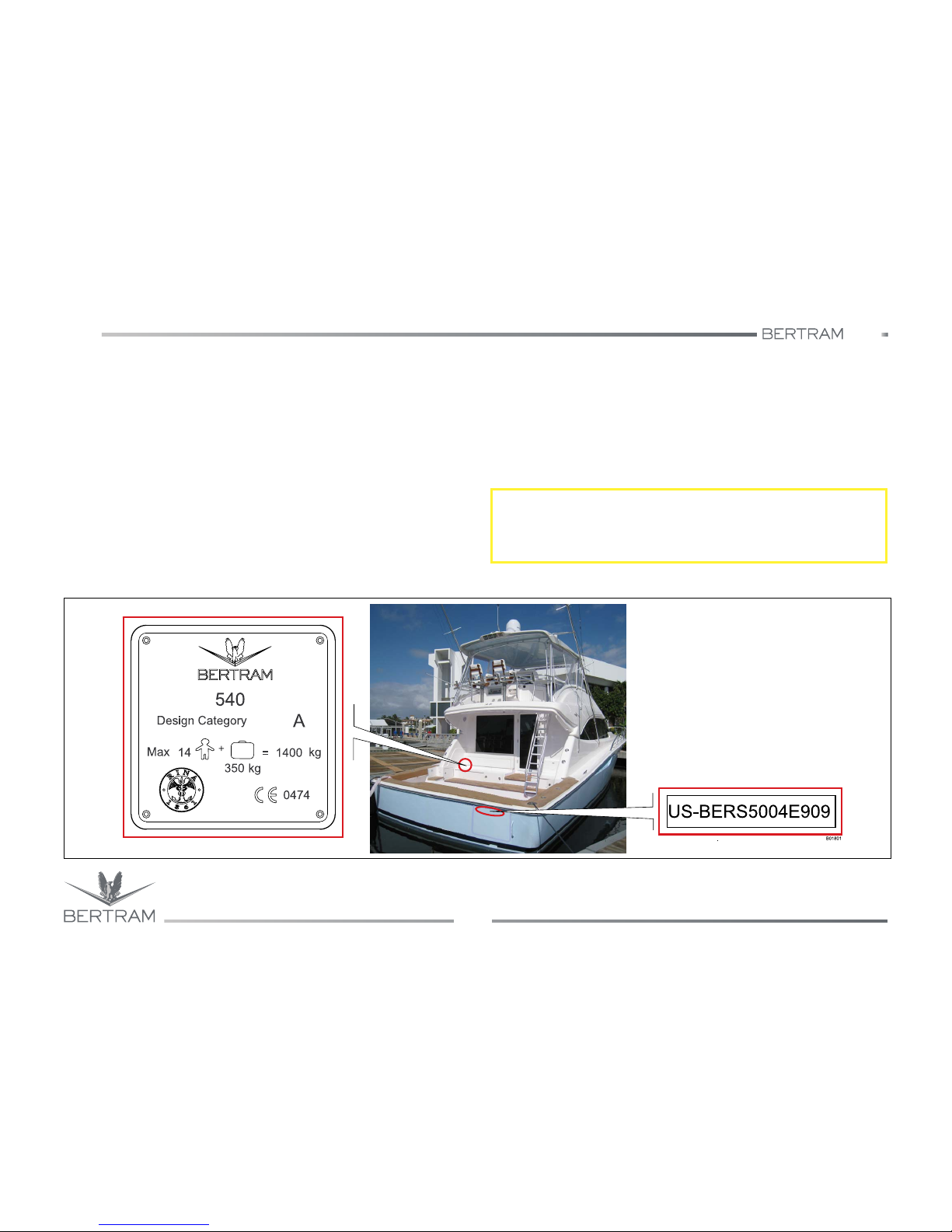
You will find the hull identification numbers affixed to your yacht in two
places.
One is integral to the hull laminate, and the other is engraved on the
transom. The hull identification number is matched to that which appears
on the Classification Certificate.
S
CAUTION
Always keep the plates readable. If deteriorated or altered, request new
plates from BERTRAM.
Page 19
540
1
FOREWORD
Studio ti 03312 540-04usa
19
NOTES:
Page 20
540
FOREWORD
Studio ti 03312 540-04usa
20
1
NOTES:
Page 21
2
HOW TO USE THIS MANUAL
FOREWORD
USE OF THE MANUAL
DESCRIPTION OF THE YACHT
NAVIGATION
AUXILIARY EQUIPMENT ON BOARD
CONTROL STATION
ON THE MAIN DECK
THRUST SYSTEMS
HYDRAULIC SYSTEMS
ELECTRIC SYSTEM
DETAILED INFORMATION ON THE INTERIORS
SAFETY DEVICES AND EQUIPMENT
YACHT HAULAGE AND LAY-UP PERIOD
MAINTENANCE
TROUBLESHOOTING
Page 22

540
HOW TO USE THIS HANDBOOK
Studio ti 03312 540-04usa
22
2
2.1 READ THIS MANUAL CAREFULLY
We recommend that you read the individual manufacturer’s engine and
equipment manuals provided with the yacht to gain a deeper
understanding of the yacht and its systems.
This Yacht comes with the BERTRAM Limited Warranty, which describes
the terms and conditions under which defects in your yacht will be
repaired. Familiarize yourself with the warranty and follow instructions
regarding proper operation and maintenance. Lack of attention to
instructions can void the warranty.
Before operating equipment associated with your yacht, particularly the
engine, read the manufacturer’s manual concerning the equipment to be
used.
Page 23
540
2
HOW TO USE THIS HANDBOOK
Studio ti 03312 540-04usa
23
2.2 STAY ALERT
Throughout this manual, we present critical information, messages,
requirements, and safety alerts in a label format to draw your special
attention to the information offered.
These messages begin with a signal word, e.g. “danger”, “caution”, etc.
as follows. The signal word is the indicator of the level of the hazard being
addressed in the message. See the following for hazard signal word
definitions.
k
DANGER
Indicates an imminently hazardous situation that, if not avoided, will
result in death or serious injury. The use of this hazard signal word is
limited to the most extreme conditions.
S
CAUTION
Indicates a potentially hazardous situation that, if not avoided, could
result in death or serious injury.
j
WARNING
Indicates a potentially hazardous situation that, if not avoided, may
result in minor or moderate injury or property damage. This signal word
may also be used to alert against unsafe practices.
i
ENVIRONMENT NOTICE
Draws the attention to risks associated with toxic substances and
environmental pollution.
NOTICES
Draws the attention to important information and reminders.
MAINTENANCE
Shows the time necessary for the maintenance to be carried out on the
different devices on board.
Page 24
540
HOW TO USE THIS HANDBOOK
Studio ti 03312 540-04usa
24
2
2.3 SPECIFIC SAFETY WARNINGS
Fire risk:
It indicates a fire risk.
Electrocution risk:
It indicates an electrocution risk.
Burn risk:
It indicates a burn risk.
Forbidden areas:
It forbids the access, the transit or the stop in a dangerous area.
b
DANGER
The cause of the fire is described here.
a
DANGER
The cause of the electrocution is described here.
c
DANGER
The cause of the burn is described here.
d
DANGER
The forbidden area is described here: it is forbidden to gain access to
dangerous areas or to approach moving mechanical parts.
Page 25

540
2
HOW TO USE THIS HANDBOOK
Studio ti 03312 540-04usa
25
2.4 KNOW YOUR RESPONSIBILITIES AS A YACHT
OWNER/OPERATOR
If your Bertram is to be operated in the waters regulated by the United
States Coast Guard, there are certain requirements that must be met.
These requirements are discussed in the Coast Guard Publication
Federal Requirements for Recreational Boats.
As a yacht owner, you are responsible for being informed about a variety
of laws (state and Federal, in the U.S.) and regulations that apply to the
navigation, operation and equipping of your yacht.
In the United States, the Federal government, through the U.S. Coast
Guard, specifies the requirements for PFD’s (personal flotation devices,
a.k.a., “life jackets”) and other required safety equipment that must be
carried aboard recreational yachts.
PFD’s and the other safety equipment must be approved by the Coast
Guard and/or other safety standards organizations. If approved, there will
be a label indicating this on the equipment. States may impose additional
requirements. Know the regulations for your areas of operation.
The yacht’s owner and/or operator, is responsible for knowing the
navigation and safety rules and good seamanship practices. Take the
time to learn the Nautical Rules of Navigation (COLREGS) that are found
in the Coast Guard publication “Navigation Rules - International and
Inland”. CG-169 that is required to be carried on all yachts over 39.4 feet
(12 m) in length. Study navigation techniques and the safe practices for
operating Your yacht and its equipment.
You are also the key person ensuring the safety of your passengers,
crew, and of the yacht. Please take time to study the chapter on SAFETY
in this manual for important information about safety procedures.
Every yacht owner and operator must be knowledgeable about the yacht
and its systems. Because you are responsible for the operation of your
yacht, we provide you with information on those topics. For each system
on board, we have provided a detailed description, including schematics
where appropriate, as well as information on maintenance and
troubleshooting.
There is a variety of instructional books, courses and videos available to
help you improve your knowledge of the Rules of Navigation, navigation,
yacht operation, operation of marine electronics, maintenance, etc.
Consult the resources listed in the appendix.
NOTICES
United States Coast Guard Regulations state that it is the responsibility
of the vessel owner to be certain that all required equipment is onboard
and in proper working order.
Bertram has supplied you with a copy of Navigation Rules, International
– Inland.
Regardless of how much experience you have, it is important to refresh
your memory by studying the Navigation Rules on a regular basis.
Page 26
540
HOW TO USE THIS HANDBOOK
Studio ti 03312 540-04usa
26
2
NOTES:
Page 27
3
DESCRIPTION OF THE YACHT
FOREWORD
USE OF THE MANUAL
DESCRIPTION OF THE YACHT
NAVIGATION
AUXILIARY EQUIPMENT ON BOARD
CONTROL STATION
ON THE MAIN DECK
THRUST SYSTEMS
HYDRAULIC SYSTEMS
ELECTRIC SYSTEM
DETAILED INFORMATION ON THE INTERIORS
SAFETY DEVICES AND EQUIPMENT
YACHT HAULAGE AND LAY-UP PERIOD
MAINTENANCE
TROUBLESHOOTING
Page 28
540
DESCRIPTION OF THE YACHT
Studio ti 03312 540-04usa
28
3
3.1 MAIN DIMENSIONS AND WEIGHT DATA
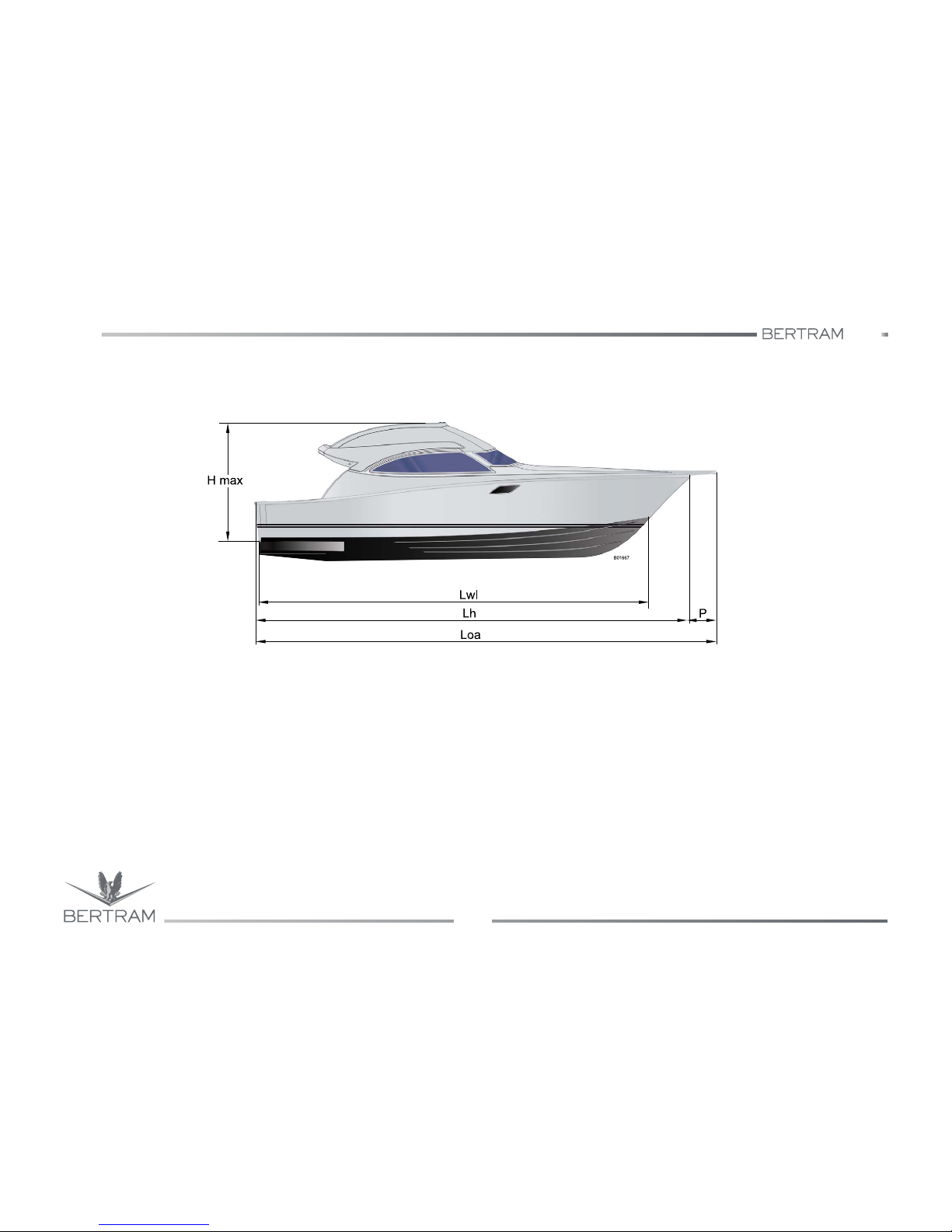
− (Loa) Length overall with fore pulpit 57 ft 1 in - 19.03 yd
− (Lh) Length hull (standard ISO 8666) 54 ft 2 in - 18.04 yd
− (Lwl) Length waterline,
yacht fully laden 47 ft 8 in - 15.90 yd
− Fore rail extension pulpit 2 ft 11 in - 0.98 yd
− Maximum Beam 16 ft 11 in - 5.64 yd
− Draft under propellers (yacht fully laden) 5 ft - 5 in - 1.65 m
− Hmax = Building height from keel
to console 1 ft 4 in - 5.9 m
− Displacement, unladen 64,375 lb - 29.2 ton
− Displacement fully laden 82.853 lb - 37.58 ton
Page 29

540
3
DESCRIPTION OF THE YACHT
Studio ti 03312 540-04usa
29
3.2 MAIN TECHNICAL DATA
Main Propulsion Engines
Model CATERPILLAR C32
Power 1676 mhp/1232 kW at 2300 rpm
Max fuel consumption per engine 327 l/h - 86.4 US gal
Fuel tank capacity
1400 US gal - 5300 l
Water tank capacity
225 US gal - 850 l
Black water (sewage) tank capacity
101 US gal - 380 l
Gray water (sewage) tank capacity
37 US gal - 130 l
Electrical power
AC Volts: 230
DC Volts: 24
Hz: 50
kW: 22+13 (optional)
Batteries
Six batteries for engines
Six for service
One battery for each generator
Bilge pumps
Two pumps in the helm gear compartment
Two bilge pumps in the engineroom
Two pumps in fore stateroom area
S
CAUTION
BERTRAM yachts are designed to obtain a correct transversal trim with
full-optional equipment, and with spare propellers and shafts.
If the yacht is not equipped with full optional, spare propellers and
shafts, some weights might have been installed to correct the
transversal trim.
The above-mentioned weights can be removed or displaced as soon as
the yacht is provided with new equipment.
Page 30
540
DESCRIPTION OF THE YACHT
Studio ti 03312 540-04usa
30
3
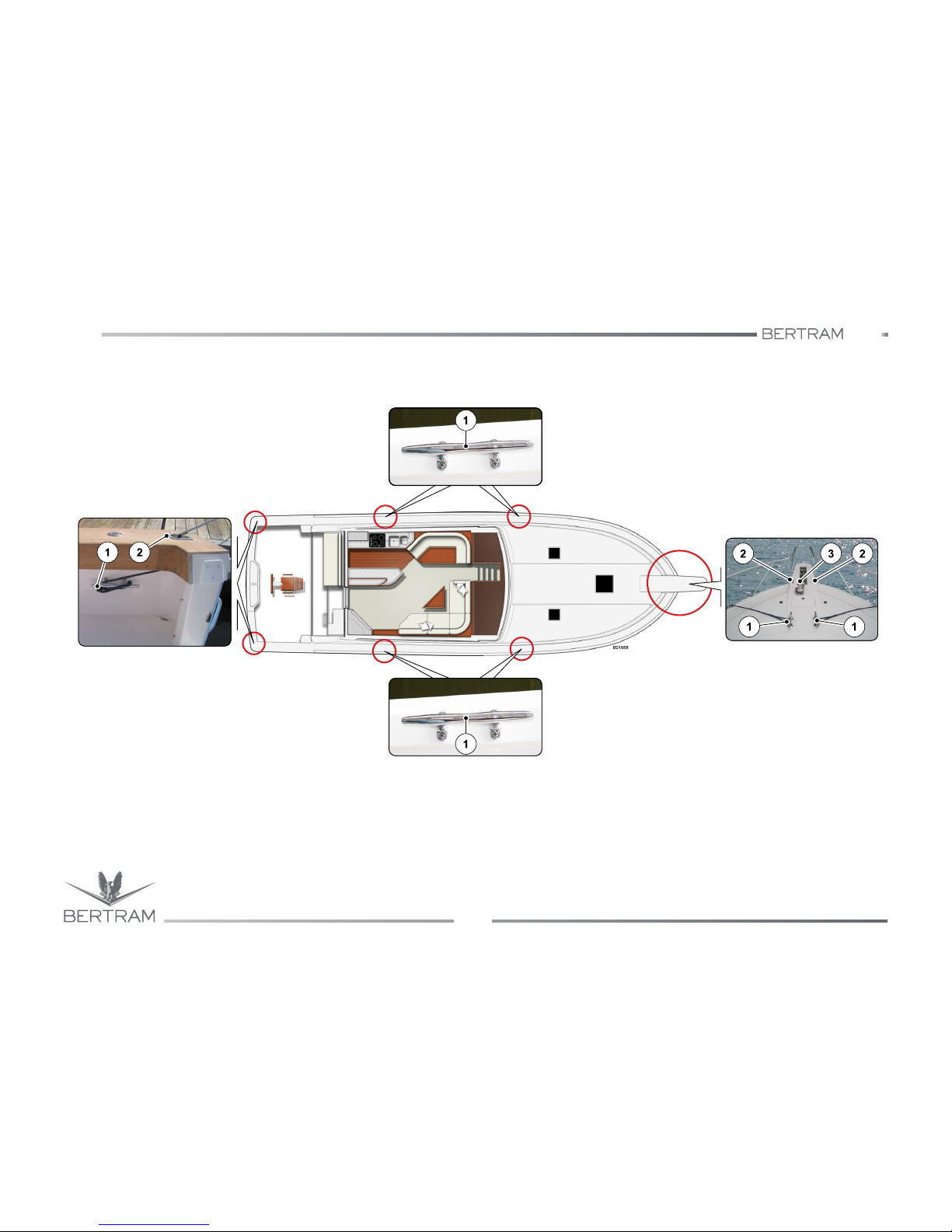
3.3 MOORING EQUIPMENT
1. Cleats
2. Chocks
3. Anchor winch
Page 31
540
3
DESCRIPTION OF THE YACHT
Studio ti 03312 540-04usa
31
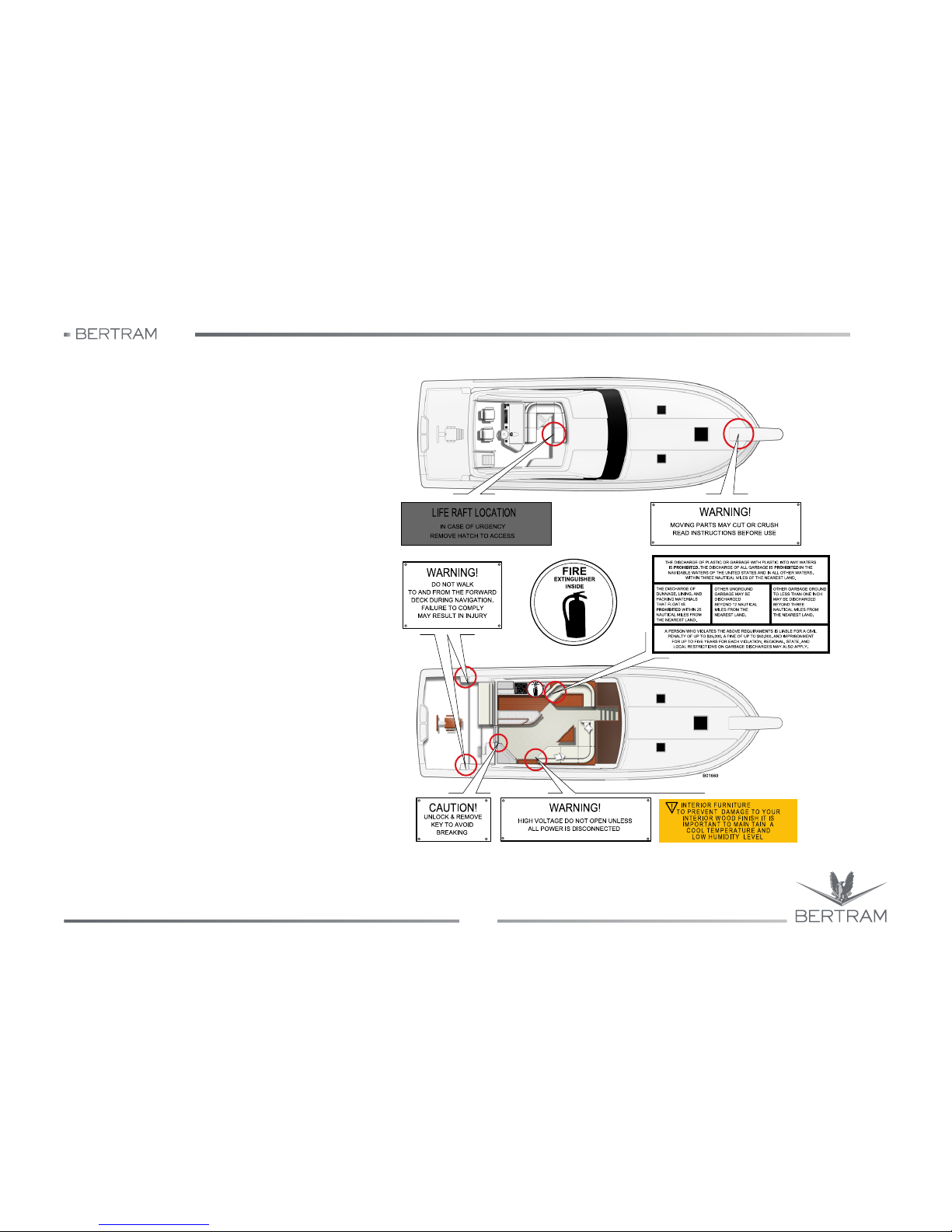
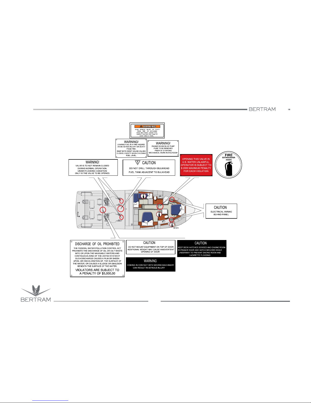
3.4 WARNING AND SAFETY
LABELS
The warning and safety labels applied as decals
on the yacht are used to point out special
features, systems or operational risks.
The labels identify the level of the hazard by the
signal word, e.g. danger, caution or warning,
followed by a notice on the nature of the hazard,
followed by the consequences that can result if
the instructions to avoid the hazard are ignored
and, finally, instructions on how to avoid the
hazard.
Before working with or on an area of the yacht or
equipment bearing such a warning or safety
label, be sure that you have read the safety
warning and that you understand the nature of
the hazard and that you act in accordance with
the instructions to avoid illness, injury, death, or
property damage.
Keep all the labels clean and legible. Replace
them if they are lost or damaged.
The extinguisher plate (A) is located near each
fire extinguisher.
This section shows the locations of the warning
notice labels with their application points.
.
Page 32
540
DESCRIPTION OF THE YACHT
Studio ti 03312 540-04usa
32
3
Page 33
540
3
DESCRIPTION OF THE YACHT
Studio ti 03312 540-04usa
33
NOTES:
Page 34
540
DESCRIPTION OF THE YACHT
Studio ti 03312 540-04usa
34
3
NOTES:
Page 35
4
GETTING UNDERWAY
FOREWORD
USE OF THE MANUAL
DESCRIPTION OF THE YACHT
NAVIGATION
AUXILIARY EQUIPMENT ON BOARD
CONTROL STATION
ON THE MAIN DECK
THRUST SYSTEMS
HYDRAULIC SYSTEMS
ELECTRIC SYSTEM
DETAILED INFORMATION ON THE INTERIORS
SAFETY DEVICES AND EQUIPMENT
YACHT HAULAGE AND LAY-UP PERIOD
MAINTENANCE
TROUBLESHOOTING
Page 36
540
GETTING UNDERWAY
Studio ti 03312 540-04usa
36
4
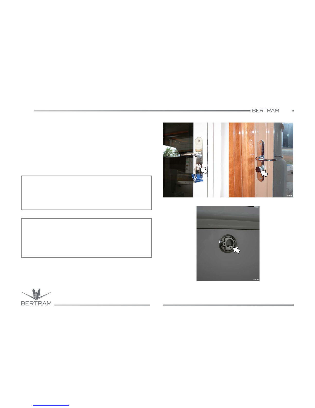
4.1 YOUR KEYS
The yacht is delivered with original keys to all the yacht’s locks.
Each original is supplied with copies. Each key has a code number
printed on it. The other locks on the yacht are universal. The same key
opens all the locks. The universal key opens a door even if it is locked
from inside. Specific task keys are described as follows. Engine keys are
provided with differently colored BERTRAM floating key holders.
Two (2) copies are included for each engine.
Keys for the sliding door at the salon entry (3 copies)
Keys for stateroom access (3 copies)
Contact BERTRAM for guidance on deteriorated or altered locks.
Before operating the yacht, you must understand the operation of all
controls, instruments, and warning systems. Read the chapters AT THE
HELM & INSTRUMENTATION AND EQUIPMENT.
NOTICES
The yacht’s helmsman should have a complete set of keys in his/her
possession at all times so that he/she can operate every lock on the
yacht. Another complete set of keys should be stored in a readily
accessible location on the yacht to be available at all times.
NOTICES
Very general and limited information for first startup and initial operation
of your yacht is included in this manual. For specific directions about the
use of the individual systems and equipment, consult the manuals
provided by the individual equipment manufacturers or contact the
BERTRAM Customer Support.
Page 37
540
4
GETTING UNDERWAY
Studio ti 03312 540-04usa
37
4.2 PREPARING TO GET UNDERWAY
4.2.1 Preliminary checklist
Accurate preliminary checks carried out with time, are fundamental for a
safe navigation. Before leaving harbour, perform the following
procedures. Details for some of the procedures in this list are found
elsewhere in this manual. Check the INDEX.
− Gather information on weather forecast and warnings.
− Consult the pilot’s book for the condition of waters in your area of
operation.
− Consult the navigation charts, in particular the distances, routes,
dangerous sea bottoms, shallow waters, and other hazards.
− Consider the cruise duration.
− Calculate the quantity of fuel required. Check the fuel onboard.
− Check the bilge flooding lights on the control station panel, indicating
the presence of water in the bilge.
− If the lights are lit, switch ON the bilge pump.
− If the pumps do not run, the batteries should be changed.
− If the pumps run, but do not discharge any water, the float switches
may be jammed or defective.
− If the pumps run, but do not discharge any water, the suction line may
be clogged.
− Check if seawater filters of both engines intake seacocks, of
generator cooling system and of A/C system, are clean. If the filter
elements are dirty, CLOSE the thru-hull fitting by moving the valve
lever perpendicularly to the thru-hull fitting body. Remove and clean
the filter baskets, reassemble the filters and then OPEN the thru-hull
valves.
− Check the engines and generator belt tension. Adjust as needed.
Check the engine oil, gearbox oil, and generator oil levels. Replenish
as indicated. V-drive oil inlet is via the dipstick opening.
− Check the propulsion engine and generator cooling water level.
Replenish as indicated as per manufacturer’s manual.
− Check that the diesel fuel filter/water separator elements are clean.
Drain any water in the filters by operating the drain valve.
− Check hydraulic oils levels of the control units for gangway, trim tabs
and steering system. Replenish as indicated.
− Check the levels in fuel and fresh water tanks.
− Check that all items (provisions, navigation charts, yacht documents,
flares, first aid kit, basic tool kit, etc.) required for a safe and
comfortable voyage are onboard.
NOTICES
After reopening the intake seacock, check if seawater filter shows
leaks.
S
CAUTION
Storeroom stowage can alter yacht balance, especially transversal trim.
Try to arrange load equally and securely, in order to avoid sudden
displacements.
Page 38
540
GETTING UNDERWAY
Studio ti 03312 540-04usa
38
4
− Ensure that the individual and collective personal safety and rescue
equipment is available and in good condition.
− Check that all loose materials are properly fixed.
− Check that the loads are distributed evenly and the yacht floats on its
lines without excessive list and in proper fore-and-aft trim.
− Check that all portlights and hatches are properly closed and secured.
j
WARNING
Equipment, and supplies loaded onboard may alter the yacht’s attitude
afloat, affecting the trim and list. Distribute loads evenly so the yacht
floats on its lines. Secure all loose items, to avoid sudden, dangerous
load movement.
S
CAUTION
Open hatches can be hazardous when the yacht is navigating. Before
sailing, make sure that all deck hatches, portlights and engine room
hatches are secured in closed position, in order to prevent injury to
persons onboard or even death and/or water penetration when the yacht
is navigating.
j
WARNING
Before starting the engines disconnect the battery charger.
NOTICES
BERTRAM furnishes the equipment required by the international
regulations.
The Owner is responsible for providing any equipment or safety device
required by national regulations in force for the waters in which the
yacht is navigating.
Page 39

540
4
GETTING UNDERWAY
Studio ti 03312 540-04usa
39
4.2.2 Safety equipment check
− Ensure that the life raft is easily accessible and properly stowed, and
that its attachment lines and safety lines are in good condition, properly
coiled and showing no wear and tear.
− Ensure that the throwable PFD’s, e.g., ring buoy, horseshoe buoy,
Lifesling® are in their correct locations on deck and that the safety line
is in good condition.
− Check extinguishers charge status. The extinguisher is charged when
the pressure gauge indicator is in the green sector.
− Ensure that individual PFD’s (lifejackets) meet the criteria for use in
the waters of operation and are approved by the authorities. Check
that they are in good condition, that the inflating device (if any) is
operational, and that the PFD’s are readily accessible in the proper
location.
See General Safety Considerations that follow in this chapter.
NOTICES
Check the safety equipment prior to leaving harbor, ensuring that all
items required are in good condition. Record the locations of this
equipment and be familiar with its correct use.
The designated helmsman must ensure that all passengers are
properly informed of safety equipment locations and of equipment
proper use (fire extinguishers, life raft, throwable PFD’s, personal
PFD’s, etc.).
Page 40

540
GETTING UNDERWAY
Studio ti 03312 540-04usa
40
4
4.3 GENERAL SAFETY CONSIDERATIONS
Do not deploy emergency signals (visual or radio) unless there is a
need for emergency service.
Every person aboard the yacht must
− know the storage location of the PFD’s (life jackets)
− know the location of their personal PFD
− know the location of the throwable PFD’s (e.g. ring buoy, horseshoe
buoy Lifesling)
− know the location of the life raft
− know how to properly put on and wear a PFD
− know how to release the personal PFD’s for use
− know how to launch a PFD
− know how to launch the life raft
− be aware of the risks posed by a fire
− know what to do in case of fire
− know the location of and be trained in the use of the fixed firefighting
systems and the portable, hand-held fire extinguishers.
People can fall overboard at any time.
Do not hesitate to ask people to wear the individual flotation devices.
PFD’s may be worn in any weather, underway, at the shore, or at anchor.
− People who cannot swim and children must always wear an individual
flotation device.
− People working on deck should wear a PFD.
− PFD’s should be worn on deck when underway in cold waters (water
temperatures below 20 °C/68 °F).
− In any emergency, passengers should put on their PFD’s
immediately.
Inflatable PFD’s (USCG Approved Type V) are comfortable to wear, and
some types will inflate automatically if the wearer falls overboard. These
PFD’s are mandatory safety devices to have for yourself and your guests.
Make sure that all PFD’s are approved by the appropriate national or
international regulatory agencies.
Read the SAFETY chapter in this manual.
Page 41

540
4
GETTING UNDERWAY
Studio ti 03312 540-04usa
41
4.3.1 Final pre-departure checklist
− Check rudder operation by putting the rudder hard over to port and
starboard, and then back to the center.
− Check trim tabs operation. Operate both tabs.
When not in use, trim tabs should be kept in the UP position.
− Check navigation lights and horn operation.
− Check the efficiency of the anchor winch and chain stopper.
− Check VHF radiotelephone operation.
− Check documents and nautical charts.
− Check proper closing of portlights and hatches and that all loose items
are secured on main deck and belowdeck.
− Check operation of bilge pumps and related indicators.
− Make sure that the engineroom ventilation system is operating.
− Check that no flammable or other hazardous materials are stowed in
the engineroom.
− Check that seawater intake valves for engine and generator cooling
and for air-conditioning system are open.
− Check that the engines and generator fuel systems’ valves are open.
− Switch on engine and user batteries.
− Switch on all 24 V circuits from the switch panel board. Check the
proper operation of each system and then switch off the systems not
to be used.
− Check the battery charge level (Volts) on the switch panel board.
Recharge the battery if indicated.
− Start the generator if you are to use it. Allow the generator to warm up
before adding electrical loads to it from the switch panel board.
− Disconnect the shore connections for fresh water and electric power,
cables and telephone.
− Check the fixed firefighting systems and the portable (hand-held) fire
extinguishers.
− Check fuel system for no leaks or fumes.
Page 42
540
GETTING UNDERWAY
Studio ti 03312 540-04usa
42
4
4.4 STARTING THE ENGINES
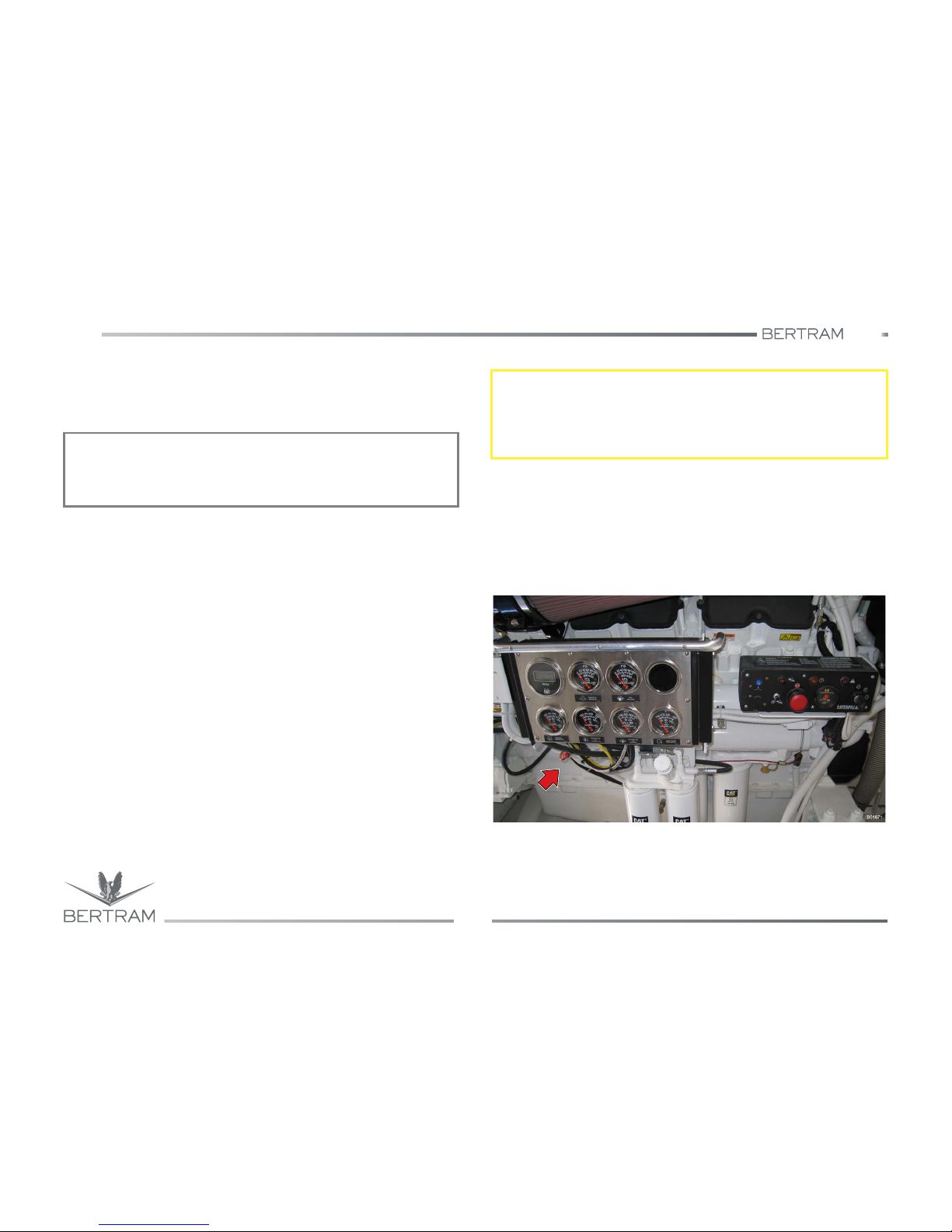
Refer to the AT THE HELM and INSTRUMENTATION AND
EQUIPMENT chapters for the location of all engine controls and gauges.
Carry out the necessary daily maintenance before starting the engines.
Check the engine room. This check can avoid following remarkable
repairs. For further information refer to the Use and Instruction Manual
delivered by the engine Manufacturer.
− The engines can have a longer life if you carry out a complete
inspection before start-up. Check following items: oil leaks, coolant
leaks, dirt build-ups. Remove dirt build-ups and repair if necessary.
− Check if cooling system hoses are cracked or show loose clamps.
− Check if alternator drive belts are cracked, broken or damaged.
− Check for the presence of loose wire connections, or worn out wires.
− Check the fuel quantity. Drain water from separator. Open the fuel
supply valve.
Oil level check
Check engine oil level only after the engine has cooled down.
− Pull out dipstick and wipe it with a clean, lint free rag.
− Place it back up to retainer.
− Pull out dipstick again.
The oil level should be between the two notches “ADD” and “FULL” of the
dipstick and must never drop below the lower notch. Add oil as
necessary.
NOTICES
Before starting the engine, check fuel level, coolant level and engine oil
level. In case of need, fill with fuel, coolant and oil mix.
S
CAUTION
Open all valves in the fuel supply line before starting the engine, in order
to prevent fuel high pressure. This pressure can damage the filter
housing or cause other kinds of damage.
Page 43
540
4
GETTING UNDERWAY
Studio ti 03312 540-04usa
43
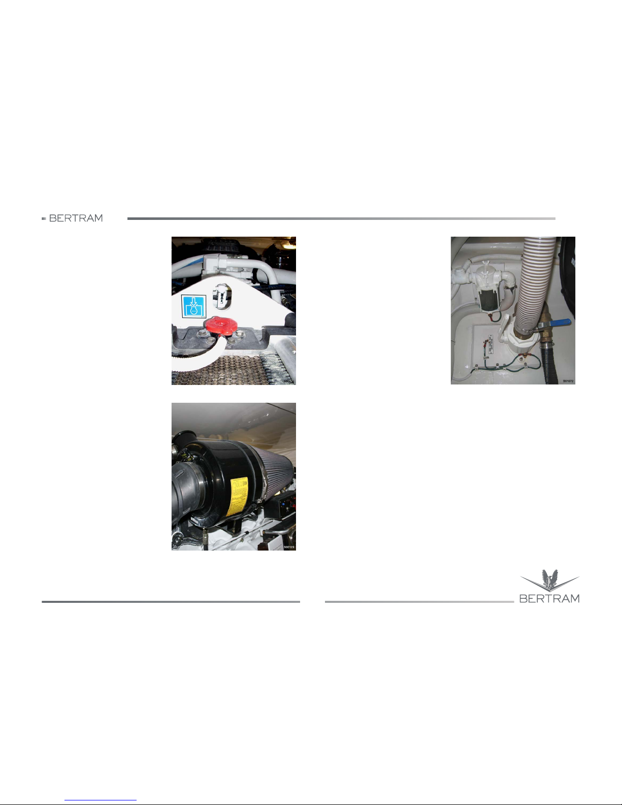
Coolant check
− Check the coolant level. Check
the level inside of recovery
tank.
− Keep the coolant level flush with
notch “FULL” of the tank.
Engine air filter indicator check
− Check the air filter clogging
indicator.
− Clean the air filter when yellow
diaphragm reaches the red
range, or when red piston locks
in visible position.
Engine sea cocks
− Open the sea water valves
inside of the engine heat
exchangers.
Page 44
540
GETTING UNDERWAY
Studio ti 03312 540-04usa
44
4
After performing the final pre-departure checklist, start the engines one
at a time.
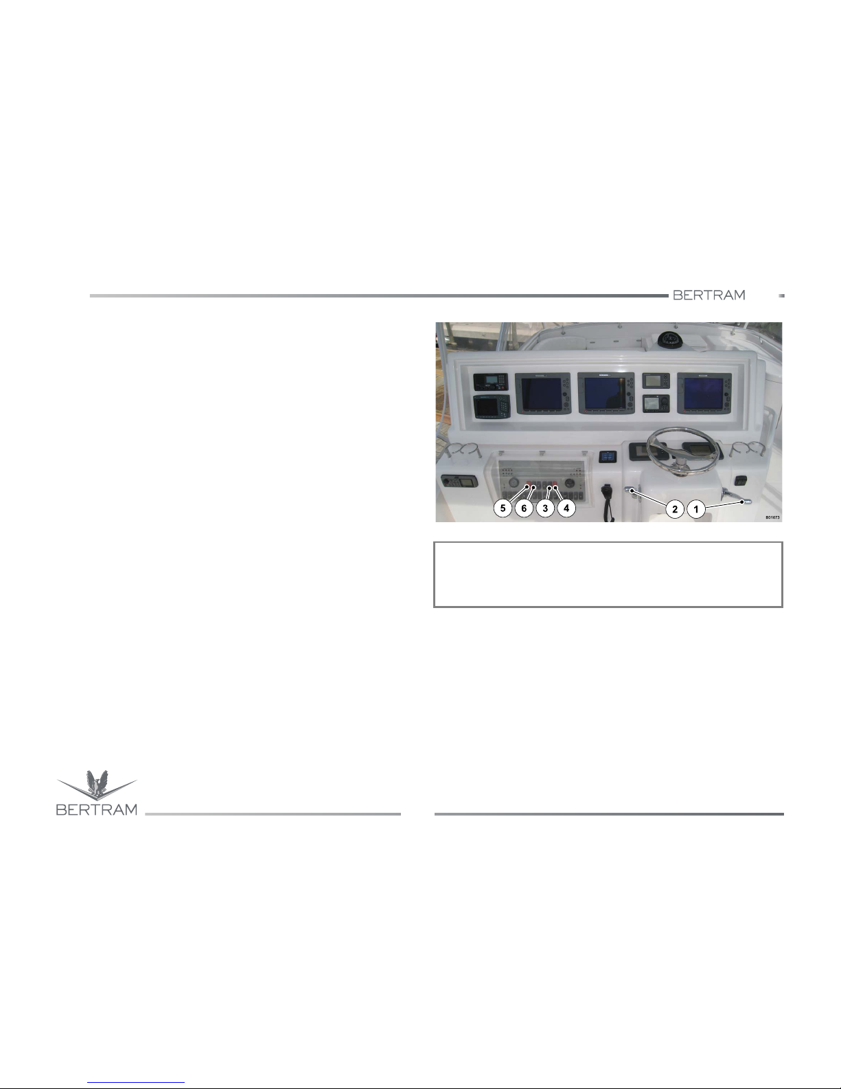
− Set control heads (1) and (2) to central idle position.
− Press the “STBD ENGINE IGNITION” button (3) to enable start-up.
− Press the starboard engine “STBD ENGINE STARTER” button (4).
− Check if oil pressure reaches the normal value within 10 seconds.
− Check if cooling water circulation is correct.
− Once the first engine is running and only when its operation has
proved to be regular, start the second engine too.
− Start the port engine in the same way as described for the starboard
one.
− Press the “PORT ENGINE IGNITION” button (6) to enable start-up.
− Press the port engine “PORT ENGINE STARTER” button (5).
Do not press or hold the throttle lever while the engine is running.
The system will supply automatically the fuel quantity necessary to
start the engine.
− If the engine does not start within 30 seconds, release the start button.
Before trying to restart the engine, wait two minutes and let the starter
cool down.
− Let the engine run with no load for about 3 minutes, until the water
temperature gauge raises. Check all devices during the pre-heating
time.
NOTICES
Check that the self-test of the monitoring system is complete, before
starting the engine under load.
Page 45
540
4
GETTING UNDERWAY
Studio ti 03312 540-04usa
45
− Run the engines idle and with no load for five minutes. During preheating carry out the following checks:
• check for liquid and air leaks;
• check all devices.
Check the devices and record the data while the engines are
operating. The data comparison will help with time to determine the
standard values of each device. This will help beside to detect a
possible wrong operation. Verify possible remarkable reading
variations.
− After the engines have run with no load for five minutes and when all
checks have been performed, increase the engine speed up to 1/2 of
rated speed.
− Verify the water drain at sea water outlet. If the water drain is not
visible, or if the water flow is not hindered, carry out following
procedure:
• stop the engine immediately;
• check that the inlet filter or the sea water strainer are not clogged,
remove clogging;
• check for leaks in the cooling system and in the auxiliary water
pumps.
− Check for liquid and air leaks.
− Carry out all necessary repairs before starting the engines.
− When all checks have been performed, set the throttle lever to idle
and start the operation.
− Check for abnormal noises or excessive smoke. Otherwise stop
engines and call the customer support.
− Check that the alternators are recharging the batteries.
− Verify the efficiency of the instruments, from the plotter to the radar,
VHF, compass, etc.
S
CAUTION
To avoid overheating and possible damages to the engines, make sure
that water drain is visible from sea water outlet and/or that water flow is
not hindered. If the water flow is hindered and/or the water drain is not
visible from sea water outlet, follow the recommended procedure.
k
DANGER
Make sure that no crew stands in front of gas exhausts and near the
mooring ropes.
S
CAUTION
Should a “magneto-thermal switch” trip, do not try repeatedly to reset it
but check the relevant electric system condition.
S
CAUTION
We suggest avoiding slow running for periods longer than 5 minutes.
The slow run implies major wear of the engine mechanical parts and is
the most harmful of the poisonous exhausts.
Page 46
540
GETTING UNDERWAY
Studio ti 03312 540-04usa
46
4
As soon as each engine starts
− First check that water is discharged from the (by-pass) exhausts.
Lack of water flow indicates a malfunction. Stop the engine
immediately. Do not operate engines without correcting this problem.
Track the source of the malfunction and service or repair as indicated.
Request CATERPILLAR service assistance if necessary.
− For each engine, check the operation of:
a. Ammeters and voltage meters. Check that the alternators are
recharging the batteries. If the warning lights are OFF, the charging
system is operating correctly;
b. Engine oil pressure gauges;
c. Engine water temperature gauges;
d. Gearbox oil pressure.
− Run the engines at 1000 rpm maximum until the normal operating
temperature is reached.
− Check for abnormal noises or excessive smoke. In case of abnormal
noise or smoke, stop the engine(s) immediately and request service
assistance.
k
DANGER
It is absolutely forbidden to perform reverse run with one of the two
engines stopped. This operation is allowed only in case of life danger
for the persons on board and for the safety of the yacht itself, however
when the engine is running it should not run higher than 1000 rpm.
Page 47
540
4
GETTING UNDERWAY
Studio ti 03312 540-04usa
47
4.5 STOPPING THE ENGINES
4.5.1 Procedure
Do not stop immediately the engines after an high load operation, but let
them run low (for approx. 5 minutes) to balance the temperature
differences.
From the helm station
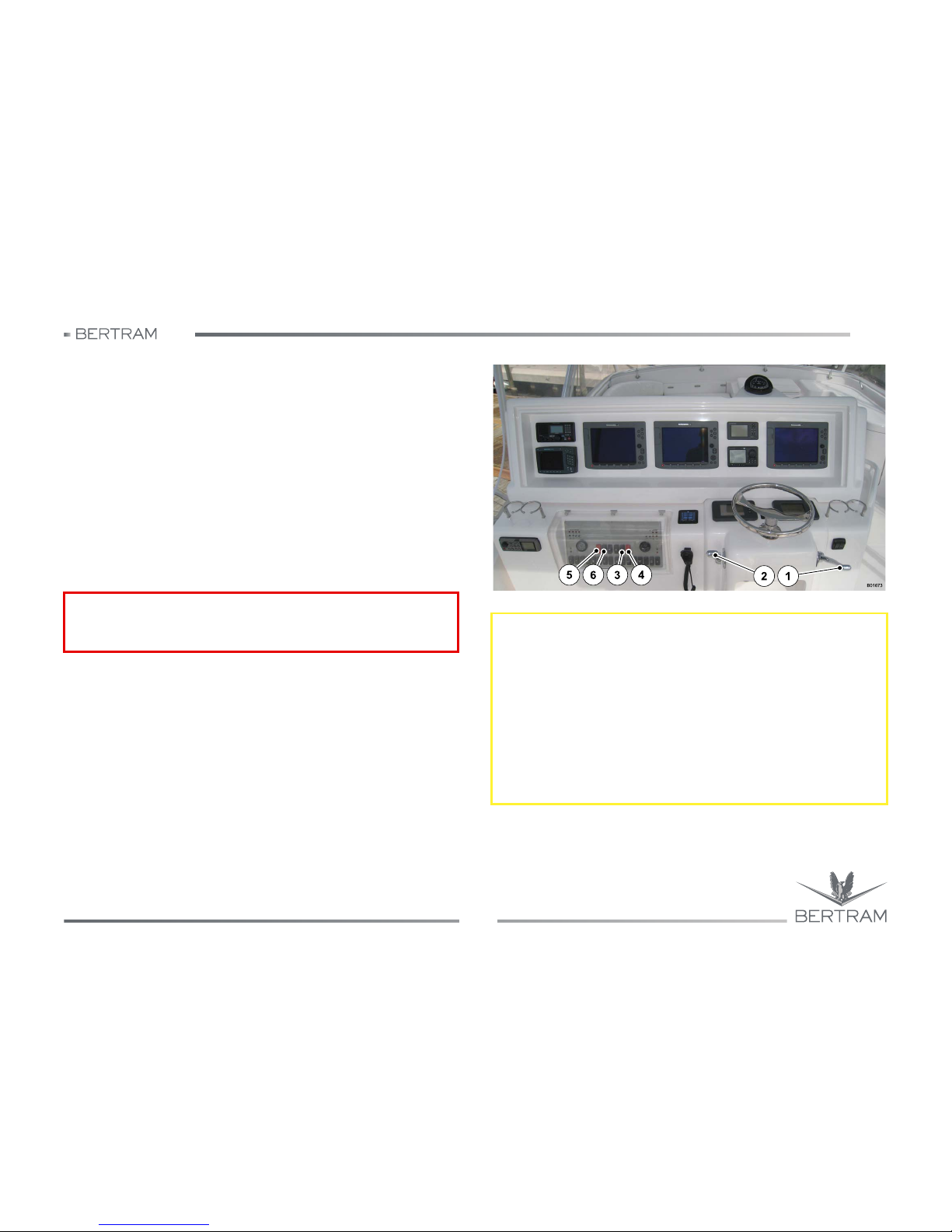
− Reposition the control heads, levers (1) and (2) into the central
position of gearbox idle run.
− Press STOP push-buttons (4) and (5).
− Press “ON/OFF” push-buttons (3) and (6) to stop the engines.
− Disconnect the circuit breakers concerning the start-up systems of
both engines.
k
DANGER
Make sure that the engines cannot be started by unauthorized staff.
S
CAUTION
With engines stopped carry out following:
− disconnect all unnecessary electric users and check the general
status of the switchboard as well as the voltmeters and ammeters
indications;
− check the switches of the bilge pumps and their regular operation;
− check for possible leaks from the shaft lines seals;
− rinse the yacht with fresh water;
− connect dock electric power supply;
− keep air extractors in the engine room running for about 30 minutes
for ventilation and air cooling.
Page 48
540
GETTING UNDERWAY
Studio ti 03312 540-04usa
48
4
4.6 ENGINES EMERGENCY STOP PROCEDURE
Due to a mechanical or electric fault, the normal procedures of engines
stop could not work; it is therefore necessary to stop the engines by
means of EMERGENCY PROCEDURES.
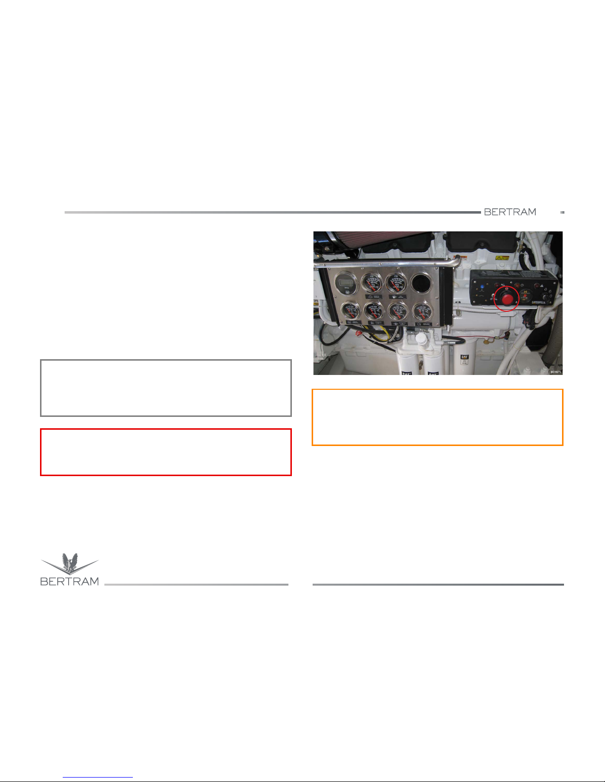
− From engineroom
Press the red push-button located on the control panel of each engine
(aside each engine).
During normal operation the emergency stop button must not be
inserted. When pressed it locks in low position and prevents the
engine start.
To reset the system to normal operation, it is necessary to turn the
button clockwise until it unlocks and returns to original position.
NOTICES
The emergency stop generates a high stress in the engines with
consequent hazard of components damage. Use only in case of real
need.
k
DANGER
Before starting the engines after an emergency stop, make sure that
you have found out and cleared the faulty reason.
j
WARNING
The emergency stop controls of propulsion engines must be used only
in case of real emergency.
Do not activate these systems during normal engines stop procedure.
Page 49
540
4
GETTING UNDERWAY
Studio ti 03312 540-04usa
49
4.7 NAVIGATION WITH ONLY ONE ENGINE
The yacht is driven by two powerful thrust systems designed to operate
together and at the same time.
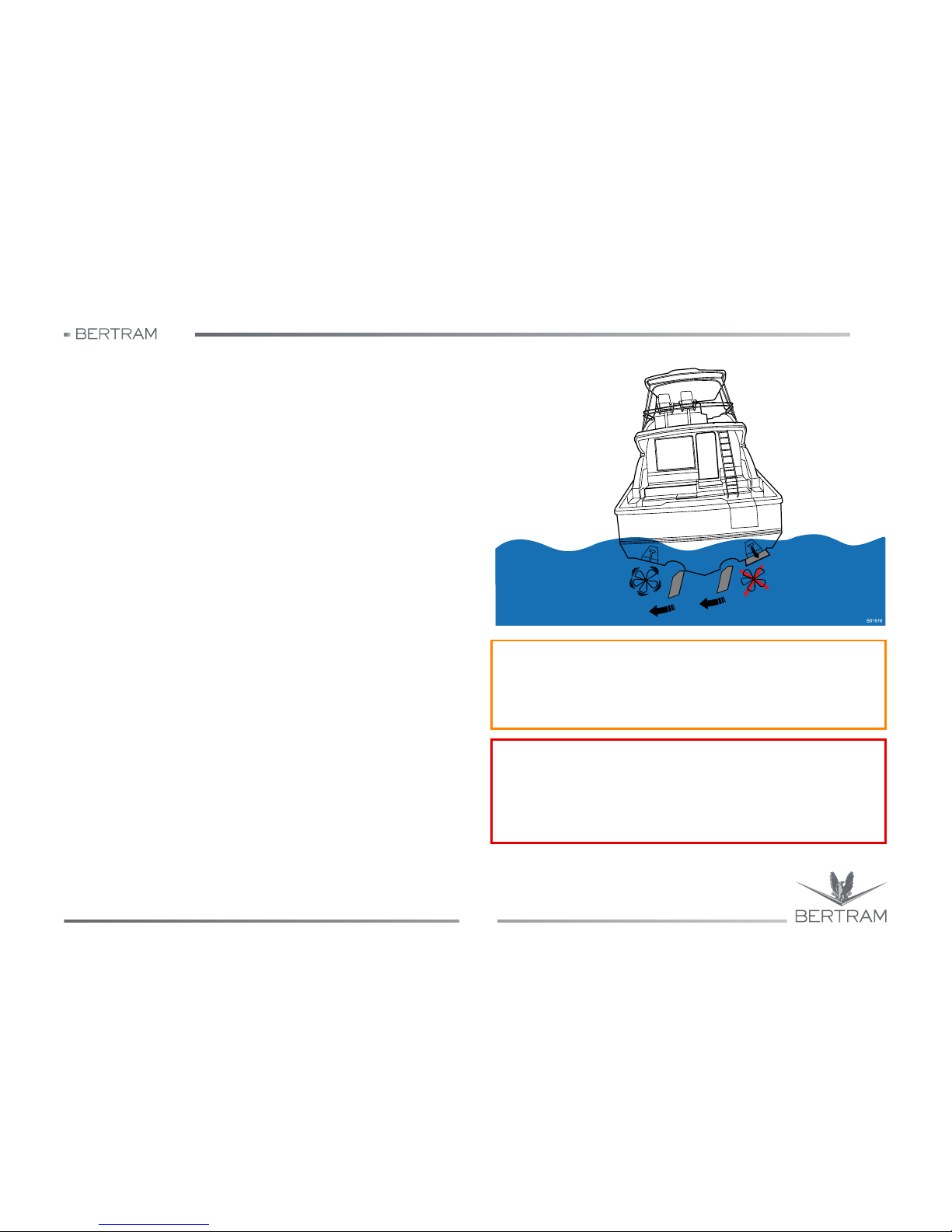
In case of failure of one of the thrust systems, you may navigate with only
one engine.
Therefore, we suggest you to:
− shut off the failed thrust engine;
− set the position of the steering wheels in the opposite direction of the
failed thrust system; in case the steering wheels cannot contrast the
asymmetric push of the operating system, lower the trim tab on the
side of the failed system, or reduce the speed;
− head to the nearest landing at a reduced speed;
− keep the yacht at a speed that allows the best manoeuvrability.
In case one engine stops due to a failure and the gear box is in idle
position, during navigation keep constantly an eye on the oil temperature
of the gear box connected with the failed system.
The propeller shaft is kept rotating thanks to the water flow through the
propeller, under these conditions also some parts of the gear box are kept
rotating.
Should the temperature increase excessively over 80°C/176°F, lock the
propeller shaft by engaging the gearbox: in this way the resistance will be
higher, because the gear box is jammed, but oil will not overheat.
j
WARNING
The yacht has been designed to navigate driven by two engines; please
remember that it is possible to navigate with one engine only in case of
emergency and for a very short time.
k
DANGER
It is absolutely forbidden to perform reverse run with one of the two
engines stopped. This operation is allowed only in case of life danger
for the persons on board and for the safety of the yacht itself, however
when the engine is running it should not run higher than 1000 rpm.
Page 50

540
GETTING UNDERWAY
Studio ti 03312 540-04usa
50
4
4.8 MOORING & DOCKING
The yacht is equipped with very powerful engines, with high performance
rudders and with a very efficient thruster.
The bow thruster should be used at very low speed for maneuvering,
without making headway; at higher speeds, engine control levers should
be in off-set use.
The ability to exploit such qualities depends on the “familiarity” the
helmsman has with his yacht. Practice is the only way to acquire
confidence, and finally you will be able to safely perform mooring and
unmooring maneuvers even in very difficult or crowded areas.
A basic rule to keep in mind is to maneuver the yacht at low speed, in
order to have enough time to react and for evaluating the situation; then,
in case of accidental contact with other vessels, you will not cause any
serious damage.
4.8.1 Before leaving the shore
Do not cast off mooring lines or weigh anchor if swimmers or other
vessels are nearby.
− Ease the mooring lines and check that everything is ready for casting
off lines, all lines are clear; nothing on the yacht is entangled with
another yacht or the shore structure.
− Check the proper operation of all navigation instruments: VHF radio,
compass, radar, plotter, horn, etc.
− Unplug the shore service connection cables of TV/Telephone, shore
power electric supply, water supply, and cablemaster if connected.
− Plan maneuvers ahead of time.
− If there is more than one way to approach a berth or depart the shore,
use the most conservative maneuver.
4.8.2 Departing from the shore
− When you are ready to depart the shore, remove mooring lines.
Check for mooring lines overboard or objects that may become
entangled in the propellers. Do not engage the engine gears until you
are certain nothing can become caught in the propellers.
− Have a crew member ready with fenders to protect the yacht in the
event of wind or sea conditions that overcome your ability to control
the yacht.
S
CAUTION
Before the mooring or unmooring maneuver, ensure that engines,
gearboxes, rudders and bow thruster (if installed) are in working order.
During such maneuvers, the helmsman should prevent any unpleasant
noise, and/or wake. Before unmooring, make sure that all doors,
hatches, port-holes, etc. are closed.
j
WARNING
Before starting the maneuver, make sure that people on board,
especially children, do not obstruct operations or that they stay in
suitable places.
Page 51

540
4
GETTING UNDERWAY
Studio ti 03312 540-04usa
51
If the yacht is moored aft to the shore (Mediterranean-mooring style with
the anchor off the foredeck and the aftdeck tied to the shore):
− release the aft lines,
− haul in the anchor rope until you are sufficiently clear of the mooring
area
If the yacht is side-moored,
− release the aft lines,
− haul in the shoreside foreline while pushing the aftdeck away from the
shore and back away from the shore.
Another way to do this maneuver is to set up a spring line on which to
drive the yacht forward (toward) the shore in such a way as to force the
aftdeck outwards, and then back away from the shore. This is a highly
recommended technique to master for close-quarters yacht handling.
4.8.3 Before entering the harbor, be sure you
− check that bilges and gray/black water tanks are empty.
− check that the mooring lines are ready and coiled to run free.
− check that the mooring berth and the berthing route are free from
incoming, departing or other moored vessels
− switch on all equipment necessary for entering the harbor from the
switch panel board (anchor windlass, aft mooring windlasses, bow
thruster, etc.).
− switch off all equipment not required for harbor operation.
− raise the trim tabs.
− stop in uncongested waters and check the operation of reverse gear.
− check the operation of the horn.
− have the yacht’s boathook and fenders ready.
− check the operation of the searchlight and have a working flashlight
ready on deck when mooring at night.
− check that mooring lines and fenders are positioned correctly.
− make sure that persons onboard not involved with the mooring
operations do not interfere with the activity and, if participating, they
are properly instructed and competent to perform as directed.
If the yacht is to be moored aft to the shore (Mediterranean mooring
style), have the anchor ready to deploy. Prepare the aft lines. When the
anchor is set, haul in the aft lines and adjust the anchor rode until the
yacht is close to the shore.
If the yacht is to be side moored, haul on fore and aft lines until yacht is
close and parallel to the shore. Adjust the fenders for best protection of
the yacht’s hull.
S
CAUTION
Mooring operations on a large yacht can be hazardous for the crew. To
avoid serious personal injury or death, use only the appropriate
equipment, e.g., fenders or boathook, to push the yacht away from a
fixed or floating structure. Never allow any person onboard to attempt
pushing the yacht away from a fixed structure or another vessel by
using arms or legs.
Page 52

540
GETTING UNDERWAY
Studio ti 03312 540-04usa
52
4
4.8.4 When the yacht is safely secured to the shore
− Stop engines.
− check that all lamps on the synoptic panel are switched off and
remove the ignition keys.
− turn OFF all unnecessary electrical equipment and check all switch
positions on the electric panels.
− check the readings on the voltmeters and ammeters.
− connect the shore power supply, and any other shore connections,
such as shore water supply.
− start the battery charger when connected to shore power or when the
generator is operating.
− check the position of the bilge pump switches and confirm the
operation of the pumps.
− check that the bilges are dry.
− check for possible leaks from the shaft seals (stuffing boxes).
− raise the trim tabs to the fully UP position.
− wash the yacht with fresh water.
4.8.5 Before leaving the yacht, be sure you
− Check that the below deck lights are OFF.
− check that the navigation lights, searchlights and other external lights
are OFF.
− check that the switches for all unnecessary equipment (plotter, radio,
anchor windlass, etc.) are OFF.
− check that all necessary equipment switches are ON (automatic bilge
pumps, battery charger, etc.).
− check that the shore power cable is properly connected, has enough
slack and will not fall into the water.
− turn off the battery switch.
− check that all deck equipment is stowed correctly.
− check that no flammable liquid bottles and containers are open or
loose.
− check that there is no debris that can clog the deck scuppers and
prevent proper water drainage.
− check that the gangway is in the right position and properly secured.
− check that the yacht is moored in a manner to protect it under all
normally expected wind and sea conditions. Check that the mooring
lines keep the yacht well clear of other yachts and that the fenders are
properly positioned and secured in place.
− check the belowdeck compartment closures.
− check that all compartments, portlights, skylights and bilges are
secured and watertight.
4.8.6 Leaving the yacht unattended
If the yacht is left unattended,
− CLOSE the seawater intakes and the other thru-hull fittings below the
waterline.
Ensure that the bilge pump discharge is open.
− check the electrical panels and switch OFF all unnecessary
equipment.
− switch off the pressurization systems of water.
− check that all compartments, portlights, skylights and bilges are
secured and watertight.
− check that the yacht is securely moored.
− press the button OFF to disconnect the battery charger, located in the
engineroom.
Page 53
540
4
GETTING UNDERWAY
Studio ti 03312 540-04usa
53
S
CAUTION
Overboard outlets and drainpipes should be checked regularly, in order
to ensure good drainage. The electric system should be checked
regularly, in order to prevent fire risks on board.
j
WARNING
Do not run the engines at idle longer than necessary. Excessive idling
time can damage the engines and pollute the environment.
j
WARNING
Hot and moving parts in the engine space are hazardous to personnel.
To avoid serious injury or death from contact with hot and/or moving
parts when working inside engine space, wear appropriate safety attire,
including but not limited to safety glasses and gloves. Be extremely
cautious in proximity of hot and moving parts. Wear hearing protection
if the engines are running.
j
WARNING
When preparing to get underway, ensure that no persons are near the
engine exhaust discharges. Ensure that only the line handlers are on
deck when casting off shore lines.
NOTICES
Excessive cranking of propulsion engines can damage the starters. Do
not run the engine starter for more than 10 seconds. Allow the starter to
cool for about one minute before attempting to start the engine again.
j
WARNING
Never deactivate the battery disconnectors with the engines running or
you may damage the engine alternators.
Page 54
540
GETTING UNDERWAY
Studio ti 03312 540-04usa
54
4
NOTICES
Use the engine/users battery parallel switch only if absolutely
necessary, to provide additional battery power for starting the engines.
If your are compelled to use the “battery parallel connection”, turn off all
electric devices so as not to jeopardize their correct operation.
Disconnect them as soon as possible.
j
WARNING
Starting the engines in gear or at a higher-than-idle speed can cause
sudden motion of the yacht. To avoid serious injury or death to persons
onboard, always ensure that the gears are in neutral and the throttles
at idle before starting the engines.
j
WARNING
Open hatches can be hazardous when the yacht is navigating. To avoid
injury or death to persons onboard and/or flooding when the yacht is
underway, ensure that all deck hatches, portlights, engineroom hatches
are secured in the CLOSED position before getting underway.
NOTICES
If a circuit breaker trips, check the related circuit for any short circuits or
overload before switching on again.
Page 55

540
4
GETTING UNDERWAY
Studio ti 03312 540-04usa
55
4.9 YACHT OPERATION DURING NAVIGATION
The yacht is very efficient and is equipped with very responsive rudders;
nevertheless, because of its size and performance capability, only
persons experienced, competent, responsible, prudent and with
necessary qualifications should operate the yacht.
The yacht is manoeuvred by means of the steering wheel in the control
station. The steering wheel operates the rudders via a hydraulic system.
The steering gear operation is independent from the engine operation.
Never leave the steering wheel unattended when the yacht is navigating.
Keep in mind that the rudder effect is proportional to the propeller rpm
and the yacht’s speed, especially when moving forward. As a
consequence, the rudder efficiency is high at high rpm and speed. On the
contrary, when the engines are idling and the yacht’s speed is low, the
yacht’s reaction to the tiller angle is almost negligible.
If necessary, or when in restricted waters, you can steer the yacht with
the engines by varying and/or reversing the engine speeds and
alternating power from port and starboard engines.
At low rpm’s, operating on a single engine, alternating port and starboard
engines and using the “back and fill” method for turning the yacht is the
recommended practice. Learn and practice the skills for handling the
yacht at low speed and engine rpm.
When the yacht’s speed increases, the transition of the hull from
displacement mode to planing mode is a critical phase. The transition to
the planing mode should be done as quickly as practical to achieve fuel
efficiency and provide a comfortable motion.
The minimum planing speed depends on yacht’s displacement, the load
distribution; trim tab position and sea conditions.
Adjust speed and trim tab positions according to the sea conditions and
the loading of the yacht to ensure a comfortable yacht motion and avoid
stresses to the yacht structure from the affects of sea conditions.
The high quality engines allow running the yacht safely at cruising speed
for extended periods of time.
NOTICES
Persons operating your yacht must never be under the influence of
alcohol or drugs. The yacht’s pilot should be experienced in the use of
all instruments and controls, and know the handling characteristics of
the yacht at all speeds and sea conditions.
You should be certain that persons intending to operate your yacht are
completely knowledgeable about its proper operation. If you are not
certain about an individual’s qualifications or competence, the person
must be supervised by a qualified operator.
NOTICES
At high speed, the use of the autopilot is dangerous and not
recommended. Anyway, be always very careful during navigation also
when the autopilot is in use.
Page 56
540
GETTING UNDERWAY
Studio ti 03312 540-04usa
56
4
4.9.1 Operating in shallow water
Observing the following guidelines will improve comfort, minimize noise
inside the yacht, avoid damage and assist in the proper operation of the
yacht.
− Do not run the engines at idle longer than necessary.
− Avoid sudden accelerations and decelerations, which create stress
on engine turbochargers.
− Run at idle for a few minutes before shutting down the engines, to
allow a gradual cool-down.
− Once the yacht is at cruising speed, the engine instrumentation
readings should remain steady. However, if, during normal operating
conditions, the engine gauges show abnormal or contradicting
values, investigate for possible systems and/or equipment problems
or failures (stop the engines).
− Monitor the control panel gauges and system condition alerts
frequently.
− Check the switch panel to see if any circuit breaker has tripped due to
an electrical system fault.
− Once in open waters and well clear of other vessels, increase the
engine rpm gradually, until the desired speed is reached. Adjust the
trim tab positions for the best performance. For information on trim tab
adjustment, refer to “Trim Tabs” in the AT THE HELM chapter.
− Adjust the speed to accommodate sea conditions.
S
CAUTION
COLLISION HAZARD - Use extra caution in shallow water or where
underwater/floating objects may be present. Hitting an object at high
speed or at an acute angle can seriously injure people and damage the
yacht.
NOTICES
The best compromise in speed, to accommodate comfort and minimize
fuel consumption, is to operate the engines at 150/200 rpm under the
maximum rated rpm (also known as WOT [wide open throttle]).
NOTICES
During navigation, keep the stern tilting window closed, to prevent
engine exhaust fumes and splash water from entering the interior. As
the closure is not watertight, do not aim water directly onto the window
when washing down the yacht.
Page 57

540
4
GETTING UNDERWAY
Studio ti 03312 540-04usa
57
− Check the engine exhausts. In particular,
• very black smoke generally means dirty filters or unburned fuel due
to improper calibration of injection pumps or injectors.
• very white smoke may mean presence of water in the fuel.
• bluish smoke may mean abnormal oil combustion.
− In case of abnormal vibration, reduce speed and run at slow rpm until
the cause of the vibration is determined. If the vibration is severe, take
the engines out of gear. It may be necessary to check the propeller
condition. It may also be necessary to have a specialist check the
propeller shaft alignment.
− Perform a visual inspection of the bilges periodically.
Be aware of the fuel supply in relation to the distance you plan to cover.
NOTICES
While the yacht is underway, all persons on board must be seated in the
designated seating areas in order to prevent injury due to falls caused
by sudden yacht movements in active wake areas or in the event of
sudden changes in yacht speed or during manoeuvring. No one should
be seated on the spoiler or forward decks when the yacht is navigating.
Page 58

540
GETTING UNDERWAY
Studio ti 03312 540-04usa
58
4
4.10 PRECAUTIONS DURING NAVIGATION
− Maintain a safe speed for the sea conditions, visibility, and when near
other yachts.
− Do not exceed speed limits in harbour and confined waters.
− Follow all navigation rules applicable to the waters in which you are
operating.
− During navigation do not unlock the anchor chain stopper because
you can seriously damage the yacht foredeck.
− Provide laminated plastic reference cards for the Rules of Navigation
and have them available for quick reference at each control station.
− Consult charts for information on locations of reefs, rocks, shoals, or
other hazards to make sure that the yacht is not at risk of grounding
or collision with fixed or floating structures.
− Frequently check that your route ahead and around the yacht is
unobstructed (no yachts or objects in the expected route or
approaching your yacht).
− Frequently confirm the yacht’s position as you cruise, using all
available aids, such as charts, visual observations and bearings,
depth soundings, GPS, radar, etc.
− If the yacht is controlled by the autopilot, be especially careful to keep
a good visual watch. The autopilot cannot see.
− Before night navigation, make sure that navigation lights and search
lights are operational. Ensure that the correct navigation lights are
turned on for operation at night. Do not keep the anchor riding light on
while the yacht is navigating.
− Use navigation lights in all conditions of reduced visibility, such as fog
and rain and at all times between sunset and sunrise.
− Know the characteristics of the sea bottom prior to anchoring. Keep
well clear of other anchored yachts.
− During anchoring, pay special attention to avoiding rotating parts of
the winch and take precautions when handling the anchor chain as it
comes off the winch. Caution is needed to avoid injury to hands and
fingers. Also, take care to avoid entangling feet and legs in the anchor
rode.
− While the yacht is underway, all persons on board must be seated in
the designated seating areas in order to prevent injury due to falls
caused by yacht movements with rough sea and in active wake areas
or in the event of sudden changes in yacht speed or during
manoeuvring. No one should be seated on the spoiler or forward
decks when the yacht is navigating.
NOTICES
When navigating at night, visual sharpness is crucial for a safe
passage. To avoid collisions, reduce speed at night to compensate for
limitations of visibility. Avoid switching on inner lights that may affect the
pilot’s night vision.
Page 59

540
4
GETTING UNDERWAY
Studio ti 03312 540-04usa
59
j
WARNING
Persons entering the engine room when the yacht is navigating should
be aware of the hazards of the yacht’s motion and their potential
exposure to high ambient temperatures, hot equipment components
and operating machinery within the engine room.
Prior to entering the engine room, set the yacht on the most comfortable
heading for sea and wind conditions. Persons in the engine room
should maintain communication with the pilot.
S
CAUTION
To avoid heavy injuries or even death caused by hazards in the engine
room, avoid the contact with hot and/or moving parts, while you are
working in this area, wear proper safety clothing and also safety goggles
and safety gloves. Be extremely cautious in proximity of hot and moving
parts. Wear hearing protection if the engine is running.
k
DANGER
It is absolutely forbidden to perform reverse run with one of the two
engines stopped. This operation is allowed only in case of life danger
for the persons on board and for the safety of the yacht itself, however
when the engine is running it should not run higher than 1000 rpm.
Page 60
540
GETTING UNDERWAY
Studio ti 03312 540-04usa
60
4
4.11 NAVIGATION IN BAD WEATHER CONDITIONS
It is the yacht captain’s responsibility to ensure the safe conduct of the
yacht. The yacht’s captain must consider the sea state and weather
conditions (at present and as forecast) in determining whether it is safe
to navigate.
In consideration of these conditions, it may be necessary to reduce
speed, change the heading or seek shelter to protect the yacht from
damage and to keep all persons onboard safe.
j
WARNING
BERTRAM declines any responsibility for the improper use of the yacht,
in relation to the wave height conditions.
j
WARNING
Before setting off, it is necessary to be aware of the sea and weather
conditions you will find along the transfer route and in the area you want
to reach.
Page 61

540
4
GETTING UNDERWAY
Studio ti 03312 540-04usa
61
4.11.1 Weather
Learn to understand weather patterns and signs of change. Bad weather
and sea conditions can cause an uncomfortable and unsafe situation.
Here are a few basic weather-related rules:
− check the forecast and sea conditions before leaving and while
underway;
− a sudden change in wind direction or speed, or an increase in wave
height indicates deteriorating weather;
− if a storm approaches, immediately seek a safe harbour;
− if a storm hits, head the foredeck of your yacht into the wind;
− if you encounter fog, determine your position, set a safe course, slow
down and alert other boats of your presence with a sound signal.
ACCIDENT REPORT:
The U.S. Coast Guard and state agencies require a report to be filed by
the helmsman of a boat involved in an accident involving loss of life,
disappearance, injury requiring treatment beyond first aid, loss of boat or
property damage exceeding $500. Contact the state boating agency
where the accident occurs for a copy of the state’s accident report form.
In the absence of a state enforcement agency, contact the U.S. Coast
Guard office nearest the accident site. Other countries have other
reporting requirements. Consult your nation’s boating law enforcement
agency.
HOTLINES:
The U.S. Coast Guard offers many pamphlets on safety and other
information not covered in this Manual. Contact your local Coast Guard
unit or call the toll-free U.S. Coast Guard hotline at: 1-800-368-5647.
NOTE THAT THIS NUMBER IS NOT INTENDED FOR BOATING
EMERGENCIES.
Page 62

540
GETTING UNDERWAY
Studio ti 03312 540-04usa
62
4
4.12 ANCHORING
To know the anchor windlass operation (if installed) read the chapter
Anchor Windlass in the section ON DECK.
Your choice of anchor depends on the size and type of your yacht and the
weather and anchoring conditions you generally expect to encounter.
When selecting anchors for your yacht, bigger is better and there’s safety
in numbers. No anchor can be all things to all bottoms so have aboard at
least two anchors of different designs to handle varying conditions.
− Check that the engines battery breaker is on;
− turn the switchboard “windlass” breaker on, on the main electric
panel;
− when the windlass hand-held remote control is not used, disconnect
it and stow it away, in order to prevent contacts oxidation;
− before operating the winch, check that the wildcat clutch is properly
engaged and remove the chain stopper;
− let the yacht move backward slowly; if necessary, use the engines;
− lower the anchor until just below the waterline, and hold;
− lower the anchor until it reaches the sea bottom;
− once the anchor is engaged, leave the chain stopper on.
4.12.1 Setting the anchor
For a secure set, follow these basic guidelines
− Choose the spot to ride the anchor carefully, considering the shelter
it offers, the proximity of other boats, and whether it’s a good-holding
bottom. Remember that boats of different sizes may swing to a
different amount of anchor rode (scope) than your yacht, so give other
boats as wide a berth as possible.
− Determine the scope (length) and type of anchor rode needed for the
water depth. (See DETERMINING SCOPE in this section). If the
anchor rode is line (rope), you should have the predetermined amount
of line ready on deck. If the rode is chain, you will have to watch the
markings on the chain, as the chain is let out, to know how much chain
has been deployed.
− Approach the spot where you plan to drop the anchor. Move slowly
and put the yacht in slow/idle reverse when you’re over the desired
location. As the yacht begins to move slowly at the aftdeck, lower the
anchor to the bottom, gradually paying out the rode to almost the full
amount of scope that you have predetermined.
− Secure the chain on the windlass, or, if the rode is line, around a cleat.
This will make the anchor “bite”. Take the engines OUT OF GEAR
(put engine controls in NEUTRAL). Let out the anchor rode to the
proper scope and secure the end of the line around the mooring cleats
at the foredeck. If a chain rode is used, lock the chain with the chain
stopper. Don’t let the windlass carry the load of anchor chain or line.
j
WARNING
Operate the anchor windlass with the engines running, in order to
provide the high voltage required and reduce the stress by slowly
moving the yacht toward the anchor without passing the chain.
Page 63

540
4
GETTING UNDERWAY
Studio ti 03312 540-04usa
63
− Confirm that the anchor is set well. One of the methods of doing this
is to choose two stationary objects on shore that are abeam of the
yacht and that line up to form a range. When the objects are in line
with each other (looking at them from the same position on your yacht,
for example the main helm position) your anchor is probably set.
− Visually check your position periodically in relation to the shore
objects. Any change in the way they line up means your anchor may
be dragging and you’d better try again. Always check the anchor if
the wind increases or the yacht swings in another direction.
Learn how to use the radar and GPS to assist checking your anchored
position. Read the manuals supplied with the equipment for this
information.
4.12.2 Determining scope
The amount of anchor rode (scope) to pay out depends on:
− the type of rode you’re using;
− the weather (now and in the future);
− the bottom conditions (mud, sand, weed, grass, gravel, etc.);
− the range of the tide.
A chart of the anchorage will show the type of sea bottom and the tide
range in the area. Avoid trying to anchor on rocky bottoms. The anchor
may not be able to hold or it may get caught under a rock.
The key is to keep the angle of pull on the anchor as close to horizontal
as possible. Heavy weather or difficult anchoring conditions demand
more scope. Always keep in mind the extent of the arc or circle in which
you’ll swing in relation to other yachts in the anchorage.
In an area with a substantial tide range, you should consider the tide
range in determining scope; at high tide you may not have enough rode
out for the proper scope.
Rode: the rode is the line connecting the anchor to the yacht.
Rode length = (Foredeck Height + Water Depth) x Scope.
Scope: the scope is technically defined as the ratio of the rode length to
the vertical distance from the foredeck to the sea floor.
Scope = Rode Length / (Foredeck Height + Water Depth)
Minimum scope is 5:1 for calm conditions; norm is 7:1; severe conditions
may require 10:1.
4.12.3 Retrieving the anchor
To avoid overstressing the electric windlass, break out your anchor by
powering up to it slowly, taking in the chain or rope as you go. When the
foredeck is over the anchor, the windlass should be able to lift it vertically.
If the anchor is still stuck, stop the windlass and snub the rode around the
cleat/bitt or windlass (chain). Then power the yacht forward slowly over
the anchor until it breaks free. When the anchor is free, remove the rode
from the cleat/bitt and try the windlass again. You know the anchor is free
when the windlass is able to pull the rode and raise the anchor. Be careful
not to damage your yacht’s hull during this operation or ride over the
anchor and foul the yacht’s propellers with the rode. Do everything slowly
and gently.
A muddy or weedy bottom condition may leave the anchor and chain very
dirty. Use the seawater washdown provided on deck to clean the ground
tackle while retrieving it.
Read ANCHORING PRECAUTIONS on the next paragraph.
Page 64
540
GETTING UNDERWAY
Studio ti 03312 540-04usa
64
4
4.12.4 Anchoring precautions
S
CAUTION
The last ring of the anchor chain is fastened by a polyester rope, fixed
to the anchor peak. In case you must leave the mooring suddenly or you
cannot refloat the anchor, you can cut the line.
j
WARNING
Danger: when the winch is operating, be extremely cautious of rotating
parts; keep your feet, hands and the remote control cable at safe
distance.
S
CAUTION
Anchoring operations involve working with heavy equipment such as
anchors and chains. These operations can cause hazards to personal
safety. To avoid serious injury or death from improper handling or
accidents, ensure that persons working with the winch, anchors and
chains and lines are careful to keep a good footing on deck and that
everyone is wearing shoes. Make certain that the anchor load is
secured after unlocking the anchor prior to lowering it, and that the
winch wildcat tension is correctly adjusted. Persons involved with
anchoring operations must take care to protect hands and fingers from
the winch gears and to avoid feet or legs being caught.
S
CAUTION
The entire anchoring area must be free, in case of sudden variations of
wind and/or current direction, especially in case of night anchoring. At
night, before dropping the anchor, check that the white anchor light
works. Before dropping the anchor, check the nautical charts: anchoring
is prohibited in certain areas; in coral covered sea bottom, anchoring is
unsafe and harmful to the environment; on rocky sea bottom, the anchor
may get fouled or lost. Anchor the yacht with the engines running, both
for safety reasons and to compensate the electrical consumption of the
winch.
Check the anchoring point frequently.
The distance from obstacles or from other yachts must be greater than
the length of the chain lowered and the all round length of the yacht.
During anchor riding it is advisable to leave the winch powered. Do not
reverse the winch rotation suddenly.
NOTICES
Before using the anchor, remove the chain stopper, check that the
wildcat clutch is engaged properly and momentarily activate the anchor
winch from the main control station to check that it will operate when
needed.
Page 65
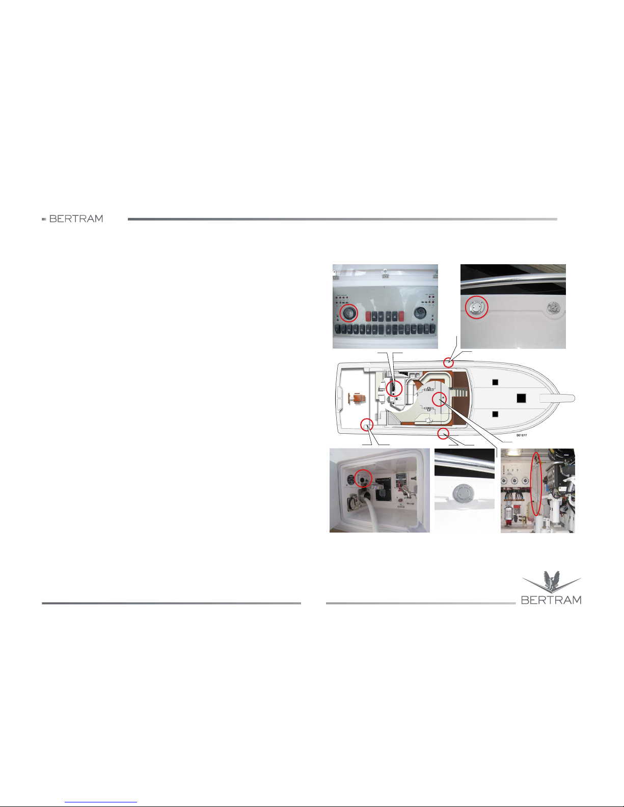
540
4
GETTING UNDERWAY
Studio ti 03312 540-04usa
65
4.13 FUELING THE YACHT
− Check that the yacht is securely moored and shut down all engines,
including the generator.
− Extinguish any open flames and do not smoke when handling fuel or
oils.
− The fuel tank fill fittings are located on the walk-arounds.
− During refuelling, check for the correct operation of the electric level
gauge.
− Remove the fuel tank fill fitting cap; check that the fuel dispensing
nozzle fits. First place the filling nozzle as deep as possible into the
filling pipe through the rubber of the anti-splash sleeve of the flow
switch. Fill the tank. Hold the nozzle steady while pumping. Never
leave the filling operation unattended.
− Fuel is harmful to the environment. Prevent any spilling of fuel. Have
absorbent materials within reach and promptly clean up any spills.
− Do not overfill the tank. Overfilling the tank will result in illegal,
polluting fuel spillage from the tank vent. To avoid tank overfilling, the
stern cockpit is equipped with a panel carrying a switch and a buzzer.
At switch activation, the buzzer starts sounding when the tank is
nearly full. By setting the switch to OFF, the buzzer stops.
Fuel fill monitor
Port fuel inlet
Visual level in the
engineroom
Starboard fuel inlet
Level gauge
Page 66
540
GETTING UNDERWAY
Studio ti 03312 540-04usa
66
4
− Reinstall the fuel tank fill cap carefully to ensure a tight seal that will
keep out rainwater and spray.
− Do not dispose of fuel, oil or other petroleum products into the
environment. Use only approved shoreside disposal facilities.
− If you are in doubt about the fuel quality at the fueling facility, see the
engine manual for the specifications for diesel fuel quality.
− At least once a month check for the correct operation of the level
gauge.
During inlet, the fuel flow produces a lot of foam; if it comes out, you might
think the tank is full. Therefore, it is good to wait for a few minutes and
then top up, in order to be sure that the tank has been filled correctly. The
special geometric shape of the tank allows also the decantation of the
impurities or of water contained in the fuel.
NOTICES
For the type of fuel to be used, follow the Manufacturer’s
recommendations. Diesel engines require very clean fuel. Keep filters
clean.
S
CAUTION
EXPLOSION/FIRE DANGER
− Stow flammable material in a safety-approved container. Never stow
flammable material in non-vented areas.
− Check bilge and engine room for fumes.
− Keep the ventilation system free of obstructions. Never modify the
ventilation system.
− Inspect the fuel system for leaks.
S
CAUTION
Refuelling should be performed at the end of navigation, in order to
allow fuel cooling down, without condense. Drain the tanks, every 2 or
3 refuelling. Before refueling, wash the teak (if installed) with fresh
water, in order to prevent the formation of fuel stains.
b
DANGER
Do not smoke during refuelling.
Do not leave the yacht unattended during refuelling.
Do not leave the engines running during refuelling.
i
ENVIRONMENT
Do not scatter fuel in the environment: it causes pollution.
Page 67

540
4
GETTING UNDERWAY
Studio ti 03312 540-04usa
67
Before & During Fueling - Checklist
− fire extinguisher - close at hand
− mooring - yacht tied securely to fueling pier
− crew - at least one knowledgeable person present
− passengers - unnecessary people off boat
− engines - stopped
− electrical equipment - power off
− windows, doors, hatches - closed
− smoking material - extinguished
− trim - fuel weight distributed equally if more than one tank
After Fueling - Checklist
− windows, doors, hatches - open
− fuel tank - secure fuel tank fill fitting cap
− spills - wipe spillage
S
CAUTION
EXPLOSION/FIRE/POLLUTION DANGER
Fuel system connections that are too loose or too tight can leak,
resulting in fuel spillage, environmental pollution and explosion/fire
hazard.
S
CAUTION
Carbon Monoxide poisoning hazard - Ensure that the engine exhaust
system operates correctly. Carbon monoxide is extremely toxic.
− The exhaust system removes the combustion gas created by the
engine and allows the correct ventilation of the stern.
− Inspect the system tightness on a frequent basis. Leaks may permit
carbon monoxide exposure.
Page 68
540
GETTING UNDERWAY
Studio ti 03312 540-04usa
68
4
4.14 PREVENTIVE MAINTENANCE
The yacht is fitted with a high number of sophisticated equipment and
systems that require periodic inspections and maintenance in order to
operate safely and reliably. One of the factors that can cause failures is
the intermittent use of the yacht and its equipment. Experience shows
that the regular use of equipment helps maintain the good operation of all
machinery and equipment. Your yacht and its systems will thrive on
regular use.
Daily checks and periodic routine and preventive maintenance are
important for maintaining the efficiency and effectiveness of your yacht’s
equipment. Failure to perform these routine periodic maintenance
schedules can result in the deterioration of the equipment’s performance
and lead to premature failures. Neglecting maintenance can lead to
unexpected problems and unsafe conditions that will reduce your
enjoyment of your yacht.
The maintenance schedule is based on time or running hour intervals,
rather than a specific calendar. For example, if a maintenance task is
scheduled every 100 hours or 3 months; such task must be repeated after
200 hours or after 6 months, after 300 hours or after 9 months and so on.
In case of a long inactivity period, e.g. winter, it is advisable to
decommission the yacht. See the Long-Term Lay-up section in the
MAINTENANCE chapter of this manual.
NOTICES
General information about ordinary maintenance tasks and
maintenance scheduling is provided in this manual. For further
information, refer to the specific equipment manufacturer’s manuals.
Page 69

540
4
GETTING UNDERWAY
Studio ti 03312 540-04usa
69
4.15 WARNINGS FOR MAINTENANCE IN HARSH
CLIMATES
Periodically check that all equipment and machinery containing water is
protected with the correct proportion of non-toxic antifreeze. If the outside
temperature goes below 0 °C/32 °F, all fresh and seawater systems are
at risk of freezing. Piping and hoses may break from freezing and this
could lead to sinking the yacht.
Systems subject to risk of freezing include but are not limited to the
engine and generator seawater and freshwater cooling systems,
watermaker system, freshwater system (cold and hot water piping,
pumps and tanks), windshield washing system, toilets and waste
systems (piping, pumps and black water tanks), air-conditioning pumps
and piping, all seawater pumps and piping, icemakers and refrigerators,
etc.
For more information on the maintenance and service requirements of
your yacht and its equipment, and for special information about
maintenance with cold weather, see the sections in this manual that make
reference to the single components, devices and equipment, but
especially consult the User Manuals provided by the Manufacturers for
specific information.
Page 70
540
GETTING UNDERWAY
Studio ti 03312 540-04usa
70
4
NOTES:
Page 71
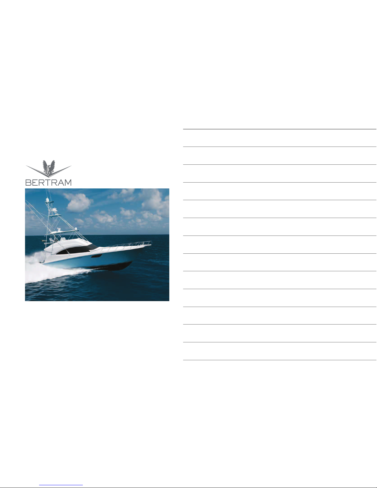
5
INSTRUMENTATION &
EQUIPMENT
FOREWORD
USE OF THE MANUAL
DESCRIPTION OF THE YACHT
NAVIGATION
AUXILIARY EQUIPMENT ON BOARD
CONTROL STATION
ON THE MAIN DECK
THRUST SYSTEMS
HYDRAULIC SYSTEMS
ELECTRIC SYSTEM
DETAILED INFORMATION ON THE INTERIORS
SAFETY DEVICES AND EQUIPMENT
YACHT HAULAGE AND LAY-UP PERIOD
MAINTENANCE
TROUBLESHOOTING
Page 72
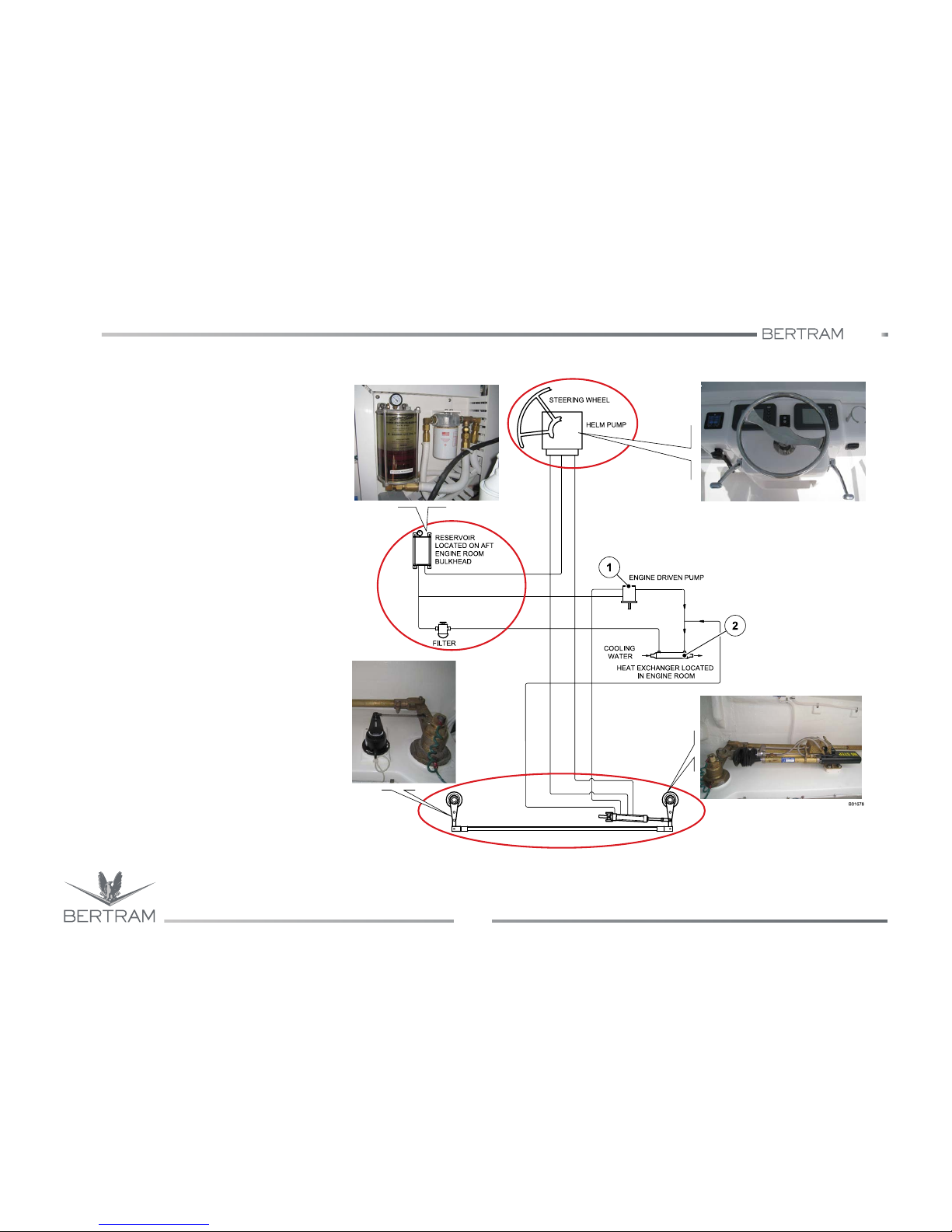
540
AUXILIARY EQUIPMENT ON BOARD
Studio ti 03312 540-04usa
72
5
5.1 HELM SYSTEM
The hydraulic power-steered helm system has
been provided to make driving easier when
underway, and to improve the safety and reliability
of the system.
Hydraulic power steering uses the ship’s engines to
provide the “power” for the steering system, via an
engine or electric motor driven hydraulic pump (1).
In the engine room there is the heat exchanger (2)
for system cooling. A manual hydraulic steering
system, consisting of a standard helm and a
hydraulic steering cylinder, (fitted with an integral
servo cylinder and a power steering valve) supplies
the “control” portion of the steering system.
Under normal conditions, with engines running, a
hydraulic oil supply is in a stand-by mode, ready to
be directed to the steering cylinder as dictated by
the steering wheel, servo cylinder and power
steering valve.
Turning the steering wheel left or right makes the
system go from stand-by into operating mode and
move the steering cylinder accordingly.
In the event of a power source failure, hydraulic oil,
from the steering helm, is automatically diverted
directly into the servo and steering cylinder,
providing the helmsman with manual back-up
steering.
An engine room mounted oil reservoir allows easy
system fill and assists the in-line oil cooler in cooling
the hydraulic oil. An in-line oil filter helps to protect
the steering system components against
contaminants.
Rudder
Reservoir and filter
Page 73

540
5
AUXILIARY EQUIPMENT ON BOARD
Studio ti 03312 540-04usa
73
The system operates in three modes for cruising: MANUAL, POWER
STEERING and AUTOPILOT. Switching from one mode to another is a
simple operation.
Manual control of steering always overrides the autopilot.
This is a safety feature and it simplifies steering control. Taking manual
control when the autopilot is on will not damage the system. Turning the
wheel to avoid an unexpected obstacle is a natural reaction. When the
steering wheel is released from manual control, the autopilot will return to
the heading it was steering without any additional intervention.
NOTICES
At high speed, the use of the autopilot is dangerous and not
recommended. Anyway, be always very careful during navigation also
when the autopilot is in use.
S
CAUTION
CONTROL HAZARD
Inspect and service the driving system regularly. An improperly serviced
driving system may get damaged, causing the sudden loss of control,
resulting in personal injury and property damage.
−
Follow instructions in owner’s information packet for hydraulic driving
system operation, for filling and bleeding procedures, for alternative
means of operation, for service procedures, troubleshooting, fluid
specifications, systems plans and replacement parts list.
−
Follow instructions in owner’s information packet for mechanic driving
system inspection and lubrication.
−
In a hydraulic system, the drive wheel movement pump hydraulic fluid
into the lines until they reach a cylinder which transfers the movement
to the rudder, aft drive; a tank holds the exceeding fluid; a valve
protects against overexposure.
−
The operator must inspect the driving system frequently for a smooth,
free and full range operation.
Page 74
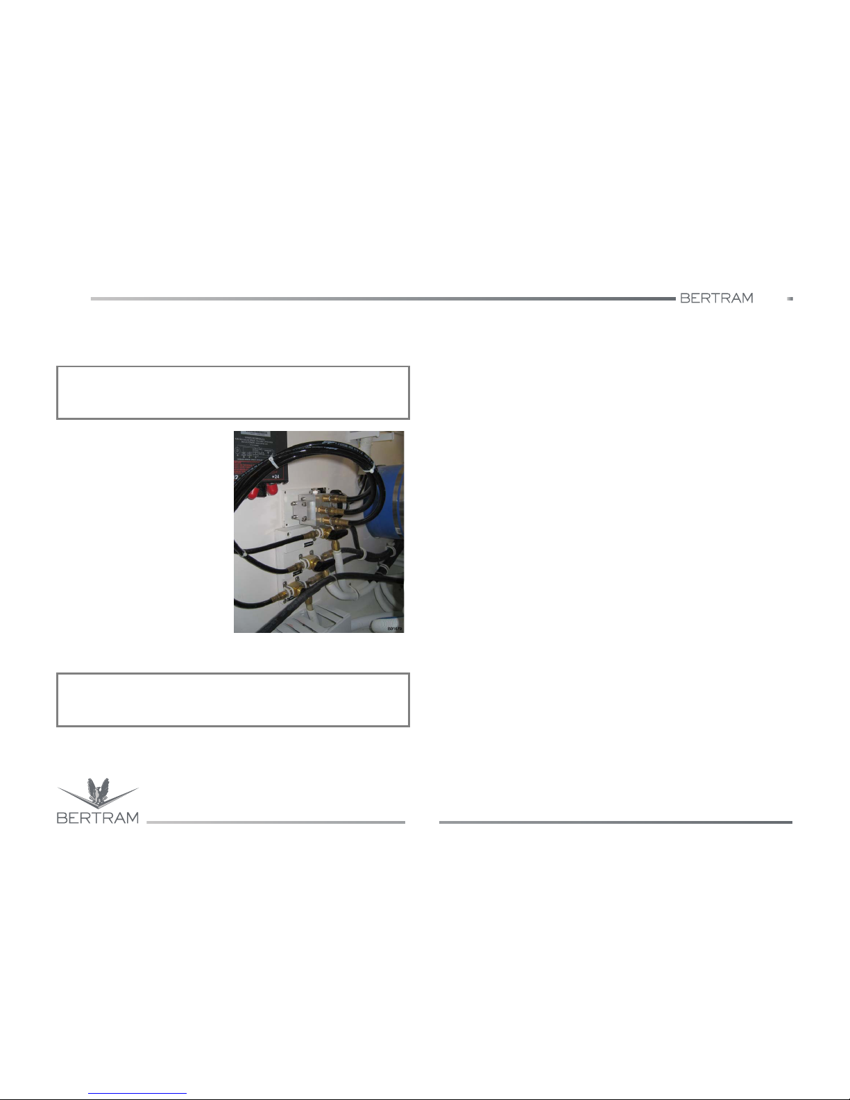
540
AUXILIARY EQUIPMENT ON BOARD
Studio ti 03312 540-04usa
74
5
The helm gear assy is located inside of the helm gear compartment and
is accessible from the stern cockpit, while the helm gear power unit is
located in the engineroom.
Near to the port rudder arm is
installed the autopilot sensor,
allowing assisted navigation by
means of the autopilot.
The power unit of the autopilot is
installed on the aft bulwark of the
engineroom; it consists of electric
motor with permanent magnets, of
a valve block with reversible pump,
of non-return valves and intake on
ports.
The pump is reversible because
the engine changes its revolution
direction according to the signals
received from the autopilot sensor.
Therefore, the pump delivers
hydraulic oil to the cylinder
chambers, according to autopilot indication.
NOTICES
Do not enter the helm gear compartment when the yacht is underway.
NOTICES
Do not remove the safety guards on the rudder coupling system.
Page 75
540
5
AUXILIARY EQUIPMENT ON BOARD
Studio ti 03312 540-04usa
75
5.2 RUDDERS STROKE (TRAVEL) CHECK
−
Turn on the helm system electrical power and activate the hydraulic
power unit.
−
Bring the rudders to the center. Observe the tiller angle indicator.
−
Turn the drive wheel all the way to one side, counting the number of
turns to the end of the stroke (travel). Observe the angle between the
rudders and the centerline (keel line) of the yacht as shown on the
tiller angle indicator.
−
Turn the drive wheel all the way to the other side, counting the turns
to the end of the stroke (travel). Observe the angle indicated on the
tiller angle indicator.
−
The number of wheel turns must be about the same in both directions.
The angle between rudders and keel line should also be equal on
each side.
−
When the check is completed, bring the rudders to the center.
j
WARNING
Should you find remarkable inaccuracy or anomaly when testing rudder
stroke, please contact the BERTRAM Service Department.
j
WARNING
The hydraulic power unit to operate must be electrically powered by the
circuit breaker located on the main electric panel.
Page 76

540
AUXILIARY EQUIPMENT ON BOARD
Studio ti 03312 540-04usa
76
5
5.3 DRIVING SYSTEM MAINTENANCE
Ordinary service
Steering maintenance requirements will vary, depending on usage of the
yacht and climate.
Bi-annual inspection by a qualified marine mechanic is required.
−
Remove, clean and grease the tilt tube annually with quality marine
grease. Lubricate cylinder support rod, support bracket holes and all
moving parts.
−
Check the steering fluid level in the helm, it should be maintained at
no less than 1/2” below the bottom of the filler cap threads.
−
Replace any hoses showing signs of wear and remove the cause or
re-route hoses. Check fittings and seal locations for leaks or damage
and service as necessary.
−
If you have installed a jack plate make sure that there isn’t any
interference between the jack plate and your steering cylinder. If there
is interference, it may occur during full tilt.
Lift restrictors or a Tilt Stop Switch - should be installed. Please consult
engine manufacturer.
Failure to comply with maintenance checks may result in loss of steering,
causing property damage and/or personal injury.
Oil level & system check
Helm mounted with wheel shaft completely horizontal must be filled to
bottom of filler hole at all times.
Do not allow oil level to drop more than 1/4” (6.3 mm). Helms mounted on
a 20-degree angle or with the wheel shaft vertical should have an oil level
within 1/2” (12.7 mm) of hole.
Check oil level periodically. At this time the steering system should be
checked for proper connections of hose, tube and fittings, possible leaks,
and the need for air removal from the system.
To do so, turn steering wheel (any one on a multisteering station) and
pressurize very hard to port.
Apply enough force to the wheel to exceed pressure relief valve pressure.
You will not harm the helm or the system. While pressure is maintained
on steering wheel, check all port (left) fittings and line connections. Repeat
procedure by turning wheel to starboard. Watch the oil level in the helm
pump when pressurizing the steering wheel in either hard over positions.
If there is no obvious drop in oil level, air was removed.
If there is an obvious drop in oil level, you are compressing air and further
filling and purging is required.
Follow steps 1 through 5 as shown on the next page.
If no leaks are obvious, your steering system is ready for use.
S
CAUTION
If leaks are found, correct before using. Failure to correct a leak can
lower the oil level in system, resulting in loss of steering.
Page 77
540
5
AUXILIARY EQUIPMENT ON BOARD
Studio ti 03312 540-04usa
77
Fill & purge procedure
NOTE: these instructions will result in hydraulic oil flushed in and out of the
system. Oil can be reused if filtered through a fine mesh screen such as the
kind used for gasoline. If unable to filter oil, an additional bottle of oil is required.
“Bleeder” may refer to cylinders with either bleed tee fittings or bleed screws.
If fitted with bleed tee fitting, open bleeder by unscrewing bleed nipple nut
two turns.
If cylinder is fitted with bleed screws, open bleeder by removing bleed screw
completely. Just loosening bleed screw will not cause sufficient oil flow to
purge system. (Helm filling can be done faster if oil is poured into the helm
prior to connecting filler tube and oil bottle.)
Cleanliness is important when handling hydraulic oil. Prevent contaminants
from getting into the oil.
−
Step 1
Screw the threaded end of the filler tube into the helm filler hole. Remove
the cap from the oil bottle and holding upright, screw into the filler tube
bottle cap. Turn bottle upside down and poke hole in the bottom of the
bottle. Fill the helm pump full of oil (oil should always be visible in the
filler tube). Use the next bottle at any time throughout the procedure when
the oil level drops in the filler tube.
Do not proceed with Step 2 until helm is full of oil.
−
Step 2
Turn the steering wheel clockwise until cylinder rod is fully extended on
the left side of the cylinder. Open left side bleeder.
−
Step 3
Holding the cylinder rod (to prevent it from moving back into the cylinder),
turn the steering wheel counterclockwise until a steady stream of airfree
oil comes out of the bleeder (drain out about 1/2 bottle of oil as required).
While continuing to turn the wheel, close the left side bleeder and let go
of the cylinder rod.
NOTICES
This procedure requires two people. One person may not be able to
remove all the air from the system, which will mean spongy,
unresponsive steering.
S
CAUTION
During the entire filling procedure, oil must be visible in the filler tube.
Do not allow the oil level to disappear into the helm - this may introduce
air into the system and increase your filling time.
NOTICES
HYDRAULIC OIL REQUIREMENTS: two quart bottles for single station
and single cylinder systems.
One additional bottle for each additional helm, cylinder, or auto pilot.
S
CAUTION
Use only your hands to restrain the cylinder rod. Do not use vise grips,
pliers or other metal tools to stop cylinder rod from moving - these tools
can damage the cylinder rod, causing leakage to occur. Ordinary hand
strength is sufficient to hold the rod.
Page 78
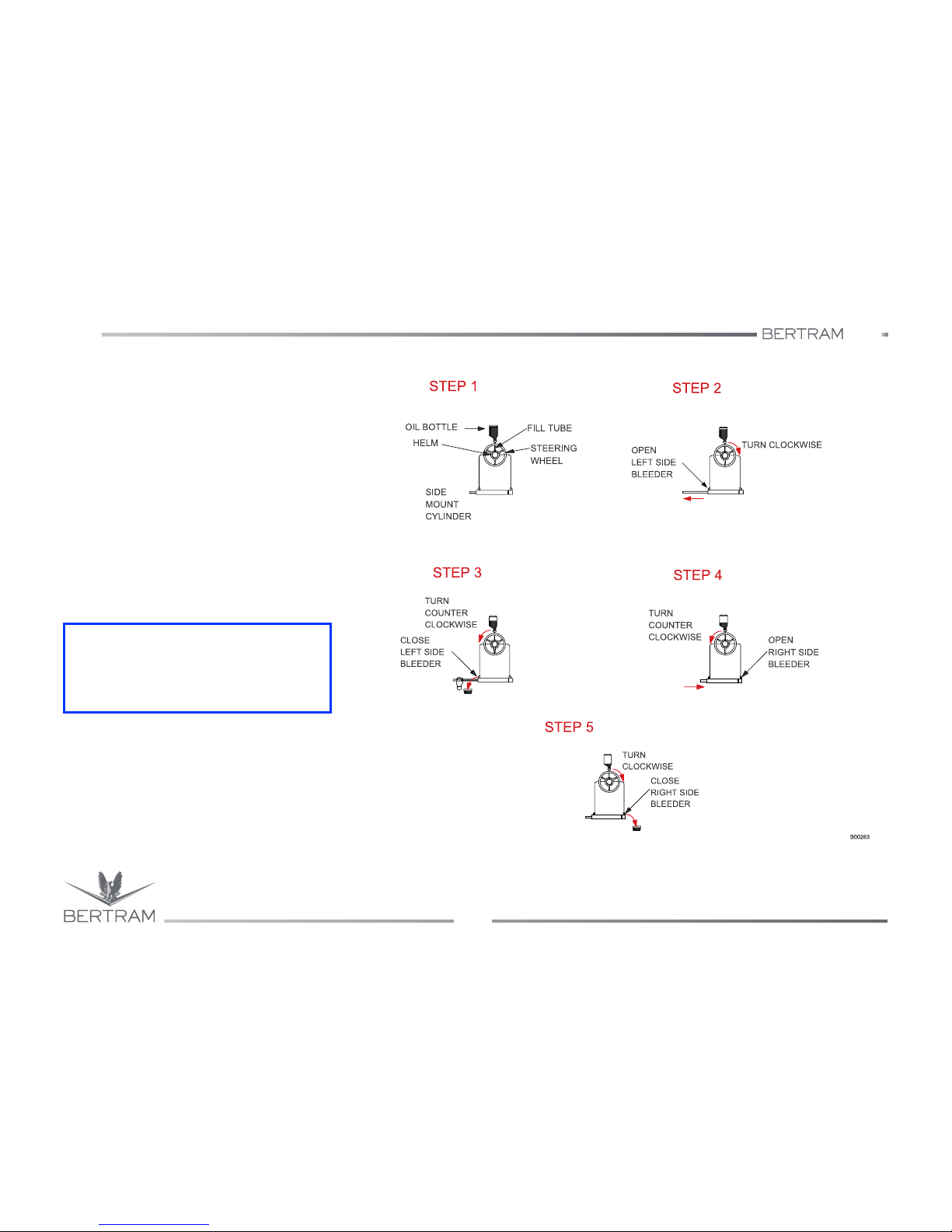
540
AUXILIARY EQUIPMENT ON BOARD
Studio ti 03312 540-04usa
78
5
−
Step 4
Continue turning the steering wheel
counterclockwise until the cylinder rod is fully
extended to the right. (Steering wheel will
come to a stop). Open the right bleeder.
−
Step 5
Holding the cylinder rod to prevent it from
moving back into the cylinder, turn the
steering wheel clockwise until a steady
stream of air-free oil comes out of bleeder.
Use only your hands to restrain the cylinder
rod. While continuing to turn the wheel, close
the right side bleeder and let go of the
cylinder rod. Fill and purge is now complete.
For more information, consult the manufacturer’s
manual.
i
ENVIRONMENT
Hydraulic oil is toxic. Dispose of old oil and oily
waste materials only in an approved toxic
materials disposal facility.
Page 79
540
5
AUXILIARY EQUIPMENT ON BOARD
Studio ti 03312 540-04usa
79
5.4 TRIM TABS
5.4.1 Trim tabs operation
The yacht is equipped with hydraulic trim tabs, that can be controlled from
the helm station. Each trim tab is driven by an hydraulic piston. They
allow you to adjust both fore-and-aft and athwartship trim of the yacht
during cruising.
The circuit is extremely simple. The electric signal coming from the
control switches in the helm station, reaches the electric pump, located in
the helm gear compartment.
5.4.2 Trim tabs general information
It is important to become sensitive to the use of the trim tabs. With
practice, you will learn how their position affects the performance of the
yacht and makes a difference in your comfort.
When you lower the trim tabs, you lower the bow toward the water. When
you raise them, you raise the bow. Adjusting the trim tabs is done
primarily to adjust the fore-and-aft and/or athwartships trim of the yacht.
5.4.3 Trim tabs basics
When the yacht is underway, adjust the tab positions to the angle that
gives the best performance and comfort.
−
When the loads aboard the yacht (fuel, supplies, passengers, etc.)
are evenly distributed and the yacht sits level on its lines, you will use
the trim tabs in a “normal” manner.
−
When weight aboard the yacht is unevenly distributed, you may have
to adjust the trim tabs individually to compensate for the uneven
weight distribution.
−
The optimum trim tab position, in calm sea conditions, provides
maximum speed with minimum friction, because the trim tabs
counteract the natural tendencies of the yacht as it moves through the
water. You will learn the best positions for the tabs through
experience.
−
With average speed, pay close attention to the trim tabs.
−
RAISE the trim tabs when going astern.
−
At the end of cruising, or when you stop the yacht, push UP both
selectors and wait for about 30 seconds to raise the trim tabs and
retract the cylinder rods.
NOTICES
The trim tabs are used to improve both passenger comfort and the
yacht’s performance.
NOTICES
RAISE the trim tabs when going astern to avoid damage to the tabs.
S
CAUTION
The trim tabs, like the rudder, can result in sudden direction changes, if
actuated too fast. It is therefore necessary to test how they respond very
carefully and in open sea.
Page 80
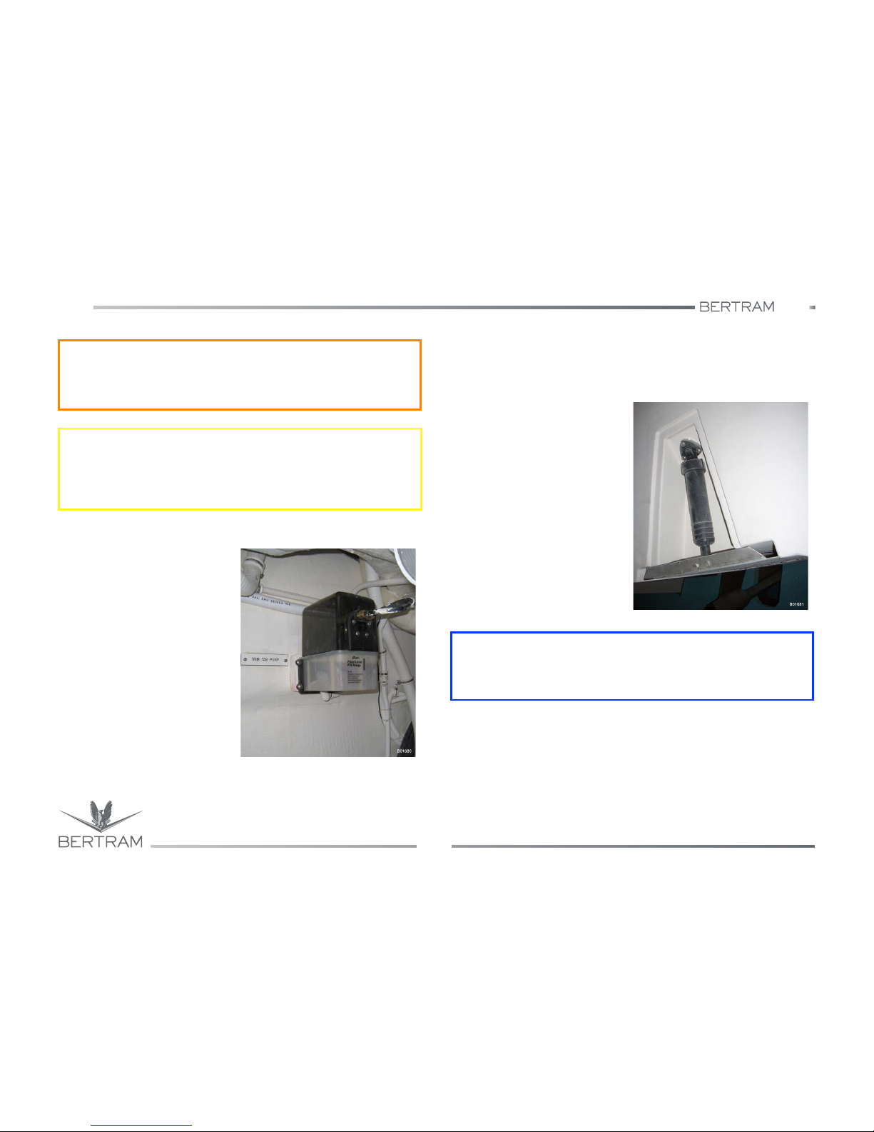
540
AUXILIARY EQUIPMENT ON BOARD
Studio ti 03312 540-04usa
80
5
5.4.4 Trim tabs oil level check
Prior to getting underway, check the
oil level visually inside of the power
unit tank.
5.4.5 Trim tab oil change
To replace the oil is necessary remove cover. Remove the fitting plug, top
up with oil as suggested by Manufacturer and lubricate the rubber gasket.
5.4.6 Hydraulic Cylinder
To prevent the cylinder rods from
acquiring barnacles that may
damage the gaskets, keep the trim
tabs control button on UP when not
using the trim tabs. Periodically
check the scraping ring on the rods
for cracks and oil leaks.
j
WARNING
Pay particular attention when using the trim tabs during fishing
operations.
S
CAUTION
A good practice when navigating is that of making sure that all
passengers are sitting down, before carrying out any maneuver when
operating the trim tabs, particularly when navigating at high speed.
i
ENVIRONMENT
Collect and dispose of waste oil according to safe environmental
practices. Use an approved toxic material disposal facility.
Page 81

540
5
AUXILIARY EQUIPMENT ON BOARD
Studio ti 03312 540-04usa
81
Item
Trim tab system
Maintenance
Check oil level before navigation
Oil change
Hydraulic cylinders
Notes and precautions
Top up, when necessary, the tank of the gear case with suitable oil.
Should frequent oil topping up be necessary, check all fittings and tubes
to find and remove the leak.
NOTICES
Clean the cylinders periodically to remove possible spots of corrosion
that can impair their efficiency. To reduce the risk of corrosion, retract
the cylinder rods each time you leave or moor the yacht, and when the
yacht is on land.
Page 82
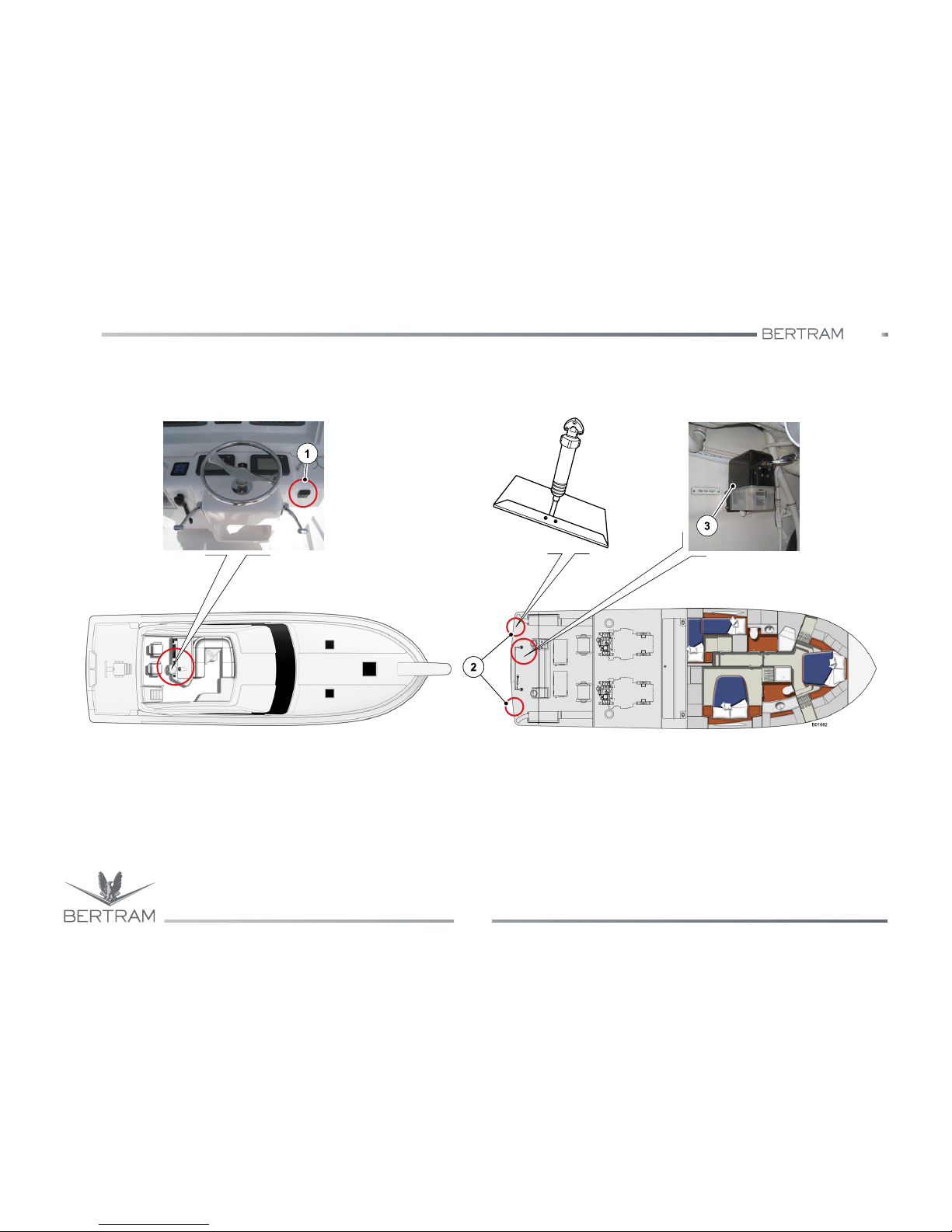
540
AUXILIARY EQUIPMENT ON BOARD
Studio ti 03312 540-04usa
82
5
1. Trim tabs controls in the helm station
2. Trim tabs
3. Trim stabilizer control unit
Trim tabs controls in the helm
station
Trim stabilizer
control unit
Trim tabs
Page 83

540
5
AUXILIARY EQUIPMENT ON BOARD
Studio ti 03312 540-04usa
83
5.5 BOW THRUSTER (OPTIONAL)
The (double) bow thruster is operated by an electric motor and is
activated from the helm station.
The bow thruster system is powered by a battery bank, recharged by a
dedicated battery charger equipped with its relevant activation switch.
A joystick operates the bow thruster controls that direct the lateral
movement of the bow during docking and close-quarters maneuvering.
The joystick movement corresponds to the required heading.
For detailed information refer to Manufacturer’s manual.
S
CAUTION
For the continuous operation of the bow thruster, refer to the handbook
delivered by the manufacturer.
k
DANGER
When the bow thruster is not used, always disconnect the control unit.
j
WARNING
Remember to disconnect power supply to the system when maneuvers
are ended or during normal navigation.
d
DANGER
Always stop the bow thruster before undertaking inspection or
maintenance tasks by disconnecting the switches and possibly also the
battery terminals.
Page 84
540
AUXILIARY EQUIPMENT ON BOARD
Studio ti 03312 540-04usa
84
5
5.6 ANTI ROLLING GYRO (OPTIONAL)
An innovative system consisting of an anti rolling gyro has been installed
to reduce the irritating effect of the rolling due to the waves; this system
is able to generate a rotation equal and opposite to the waves motion.
The ARGs system combines a sensible reduction of the rolling both with
yacht idle and in navigation, with low energy consumption, and does not
involve the life quality onboard leaving performance unchanged. Thanks
to these very important features, the device can remain active also
overnight, to maintain the best comfort on board, by almost completely
damping the annoying rolling.
The ARGs operation principle is based on a well known physical
principle: a gyro tends to maintain its own vertical rotation axis parallel to
gravitational acceleration.
When its position changes due to external reason, like the rolling
generated by waves, it reacts with a rotation on a perpendicular axis
against its own axis of rotation and against the listing cause.
With AR, this generated movement (rolling) is softened by the presence
of a damper, calibrated expressly in compliance with the specifications of
each yacht.
The system consists of two power units and of two anti rolling gyros
placed in the generator room.
For further information on their use and maintenance see the
manufacturer manuals.
S
CAUTION
The ARG is not watertight. If submerged by seawater it could get
damaged.
S
CAUTION
Have the PERIODIC ARG INSPECTION carried out by specialized
personnel every two years. Contact the CUSTOMER SERVICE for
further information.
k
DANGER
During operation the ARG components roll freely inside of their
housing; therefore to open this housing would cause injuries or even
death. In case of a fault, if it is necessary to open the housing for
checking, have this operation performed by a skilled technician.
j
WARNING
During operation the ARG, the dampers and the housing overheat.
Therefore, to avoid burns, do not touch the ARG during operation.
k
DANGER
The ARG housing is not solid. Do not lay objects on the ARG or sit on it.
Page 85
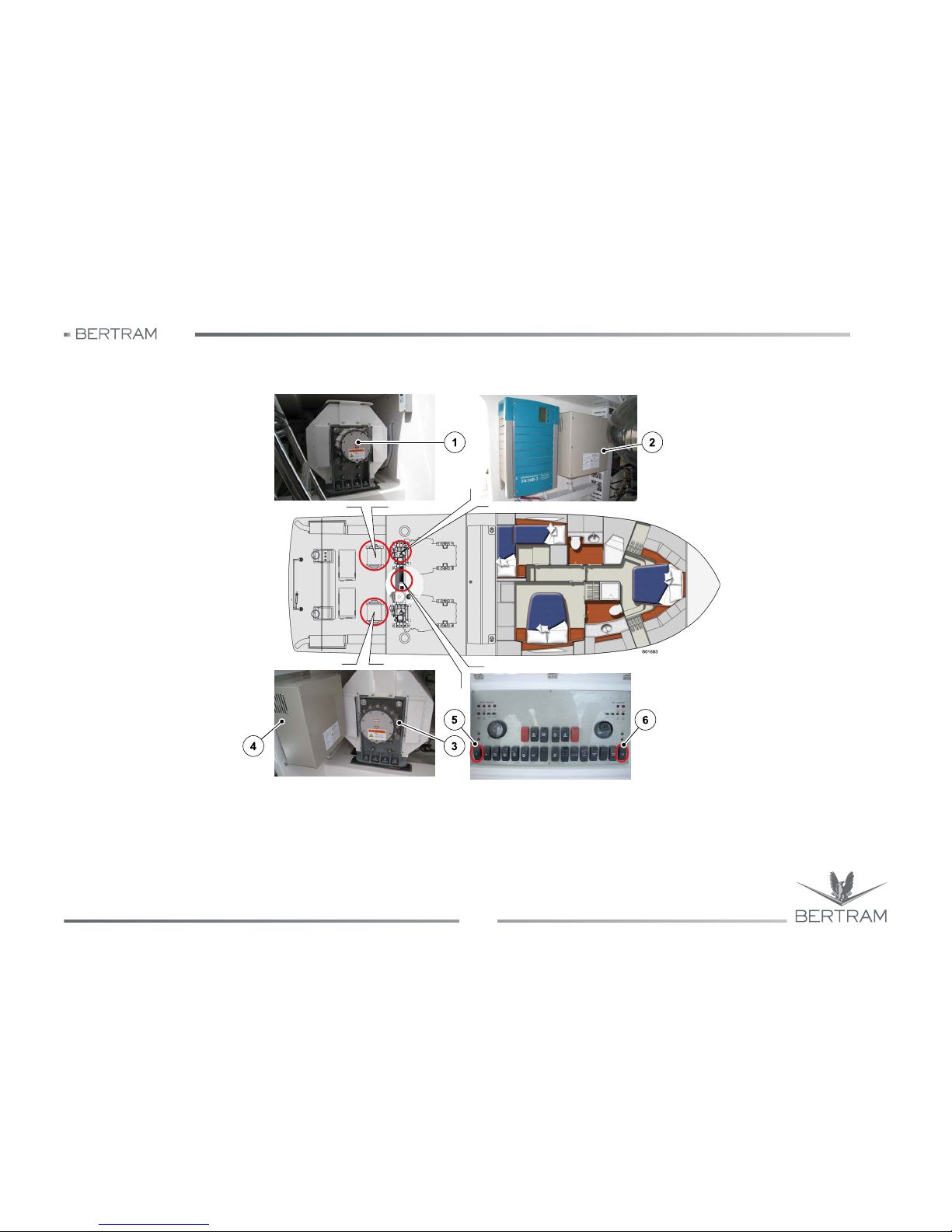
540
5
AUXILIARY EQUIPMENT ON BOARD
Studio ti 03312 540-04usa
85
1. Port anti rolling gyro
2. Power unit for port anti rolling gyro
3. Starboard anti rolling gyro
4. Power unit of starboard anti rolling gyro
5. Port stabilizer controls in the helm station
6. Starboard stabilizer controls in the helm station
Anti rolling gyro controlsStarboard anti rolling gyro
Port anti rolling gyro Port ARG power unit
Page 86
540
AUXILIARY EQUIPMENT ON BOARD
Studio ti 03312 540-04usa
86
5
NOTES:
Page 87
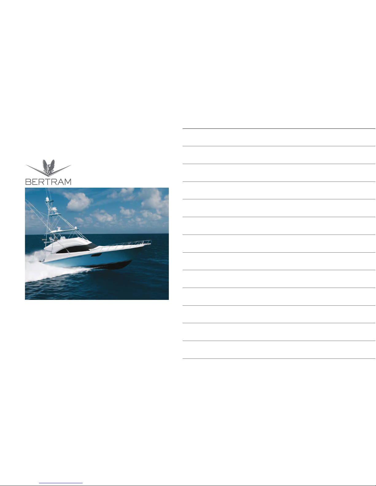
6
CONTROL STATION
FOREWORD
USE OF THE MANUAL
DESCRIPTION OF THE YACHT
NAVIGATION
AUXILIARY EQUIPMENT ON BOARD
CONTROL STATION
ON THE MAIN DECK
THRUST SYSTEMS
HYDRAULIC SYSTEMS
ELECTRIC SYSTEM
DETAILED INFORMATION ON THE INTERIORS
SAFETY DEVICES AND EQUIPMENT
YACHT HAULAGE AND LAY-UP PERIOD
MAINTENANCE
TROUBLESHOOTING
Page 88
540
CONTROL STATION
Studio ti 03312 540-04usa
88
6
6.1 CONTROL STATION
Your yacht is equipped with one helm station with drive wheel and several
navigation instruments in the flybridge area.
NOTICES
Very general and limited information for first startup and initial operation
of your yacht is included in this manual. For specific directions about the
use of the individual systems and equipment, consult the manuals
provided by the individual equipment manufacturers or contact the
BERTRAM Customer Support.
Page 89
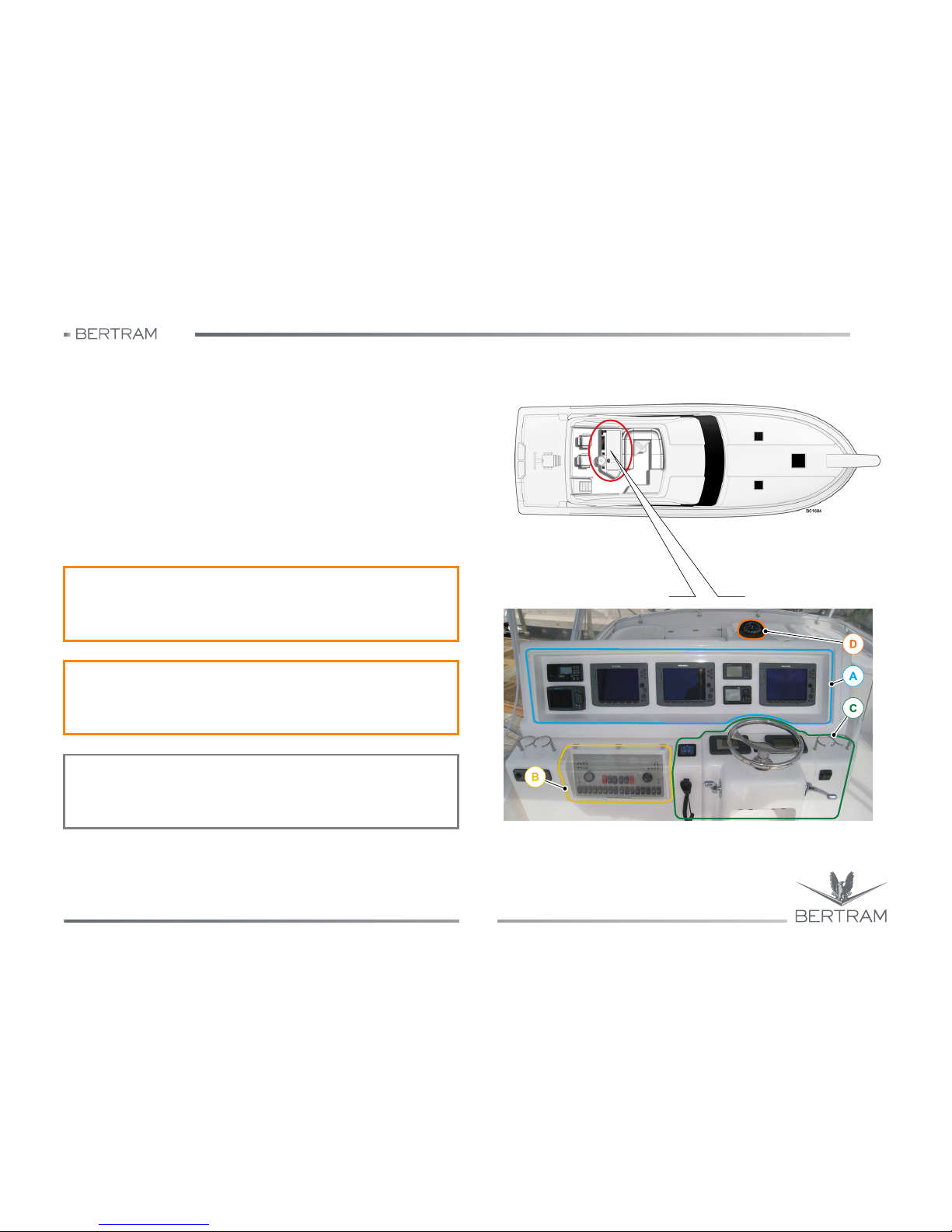
540
6
CONTROL STATION
Studio ti 03312 540-04usa
89
6.2 FLYBRIDGE HELM STATION
To understand the control devices on the flybridge helm station, review
the following main sections:
A. Navigation instruments
B. Port helm station console
C. Maneuver control levers
D. Magnetic compass
The console containing the navigation instruments (A) is closed. To
access these instruments, activate the console opening/closing switch
(12) section (B).
j
WARNING
It is a good rule to keep the screens clean by washing them with wet
and clean rags, avoiding to use chemical or abrasive products.
j
WARNING
During the yacht cleaning and washing take care not to throw water on
the electrical components.
NOTICES
The images and drawings of the helm station are referred to the USversion of the yacht.
Page 90
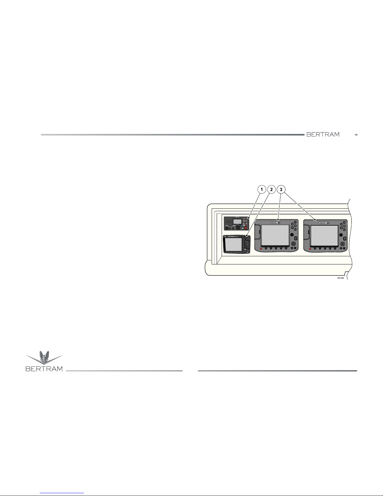
540
CONTROL STATION
Studio ti 03312 540-04usa
90
6
6.2.1 SECTION A - Navigation instruments
1. Radar display/Chartplotter/Fishfinder
It allows displaying in a clear and quick way what is happening
around the yacht, so as to facilitate navigation.
2. VHF-DSC Radiotelephone
This device allows to communicate with boats and vessels. It is
possible to carry out long distance connections with shore stations for
emergency calls and to get in touch with the research and rescue
teams. This instrument allows to carry out calls in DSC mode (Digital
Selective Call).
3. Radar display/Chartplotter/Fishfinder
They allow to display in a clear and quick way what is happening
around the yacht, so as to facilitate navigation.
Page 91
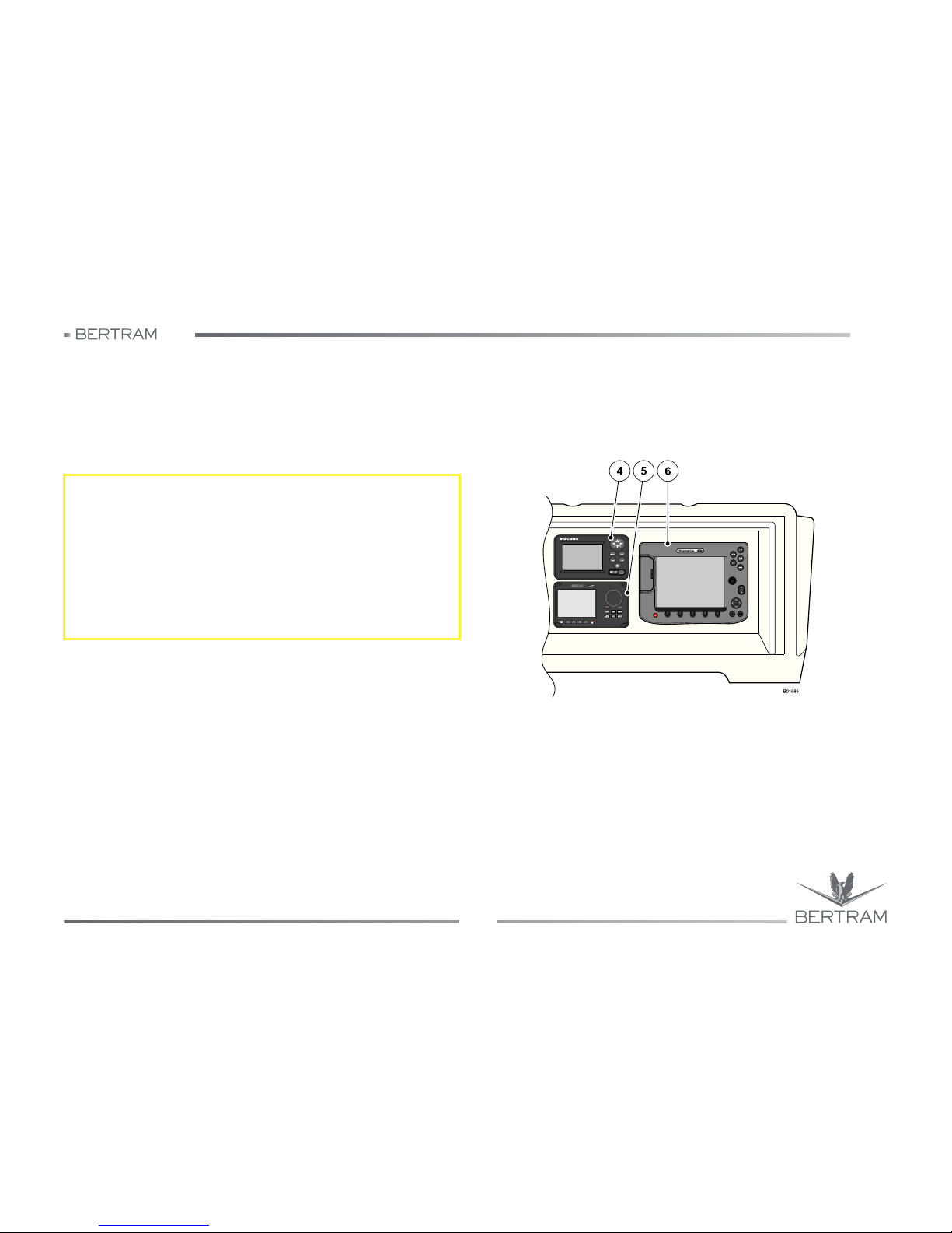
540
6
CONTROL STATION
Studio ti 03312 540-04usa
91
4. Multifunctional display
This screen allows to display the information received from GPS,
chartplotter, radar or various water temperature sensors, wind data,
etc.
5. Automatic pilot (autopilot)
This device allows holding a certain pre-set course, without having to
manually operate on the helm system.
6. Radar display/Chartplotter/Fishfinder
It allows displaying in a clear and quick way what is happening
around the yacht, so as to facilitate navigation.
S
CAUTION
If the yacht bow is facing a sudden obstacle, this can be avoided by
turning with force the steering wheel. This operation allows to steer the
yacht only if the steering wheel is held firmly. As soon as the steering
wheel is released, the autopilot resumes immediately the yacht's track.
If the obstacle is not too close, the best thing is to set the device in
stand-by, so as to take over control of the yacht definitively. Once bypassed the obstacle the device can be switched on by setting the track
again.
Page 92
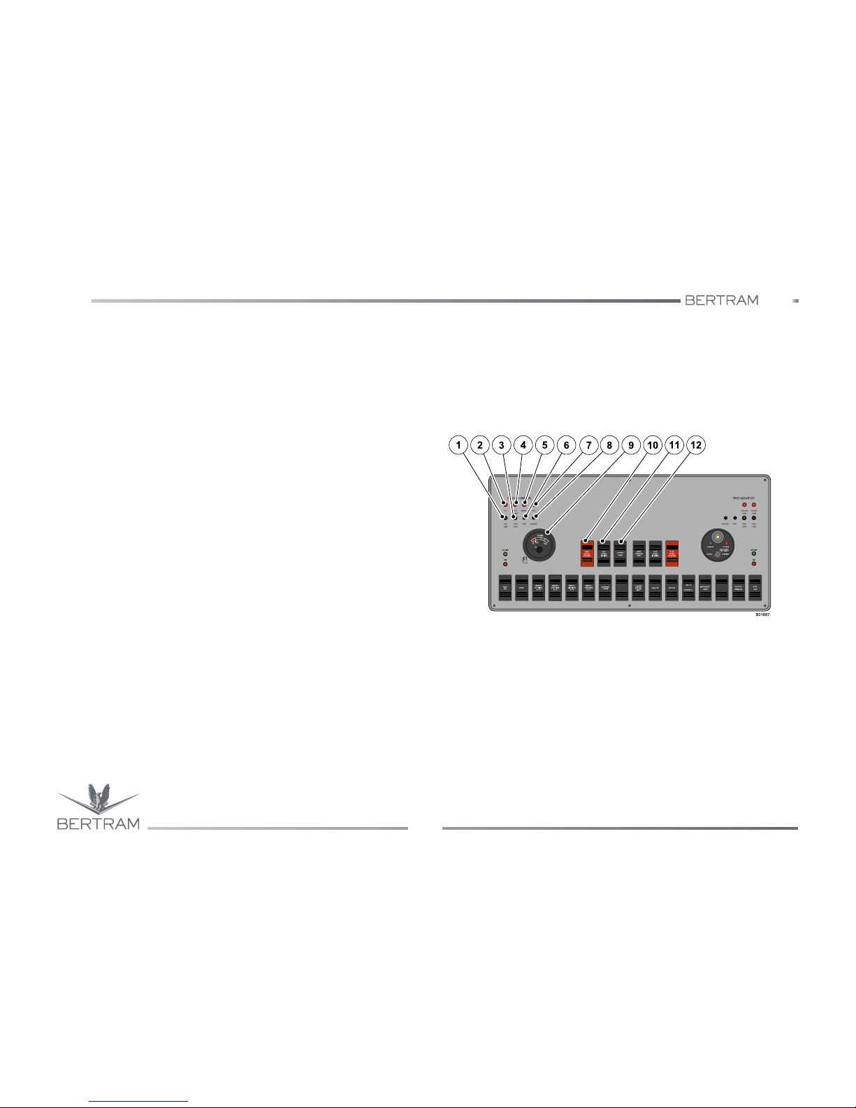
540
CONTROL STATION
Studio ti 03312 540-04usa
92
6
6.2.2 SECTION B - Port helm station console
1. Port engine exhaust warning lamp
This light indicates high temperature inside of port engine exhaust
ducts.
2. Stern bilge flooding alarm lamp
This light indicates the flood of the aft bilge.
3. Port generator light
This light indicates that the port generator is running.
4. Generator room bilge flood signal light
This light indicates the flood of the bilge in the generator room.
5. Engine room bilge alarm lamp
This lamp indicates the flooding of bilge in the engine room.
6. Test button to bilge flood signal
The test button is used to verify the correct operation of each signal
light of the panel. When using the test button, all LEDs must be ON
and buzzer must sound to indicate the correct operation of the bilge
signal system. When releasing the button all LEDs must go out and
the buzzer must clear off.
7. Bow bilge alarm lamp
This lamp indicates the flooding of the bow bilge.
8. Squelch button of bilge flood signal
This selector allows the deactivation of the bilge alarm.
9. Fuel level gauge
This gauge shows the fuel level in the tank.
10. Port engine STOP/START switch
This switch enables the start/stop of port engine.
11. Port ENGINE IGNITION switch
This switch allows to enable the start/stop of the port engine.
12. Low idle switch
This switch allows to decrease the yacht speed until this becomes
lower than the idle speed.
Page 93
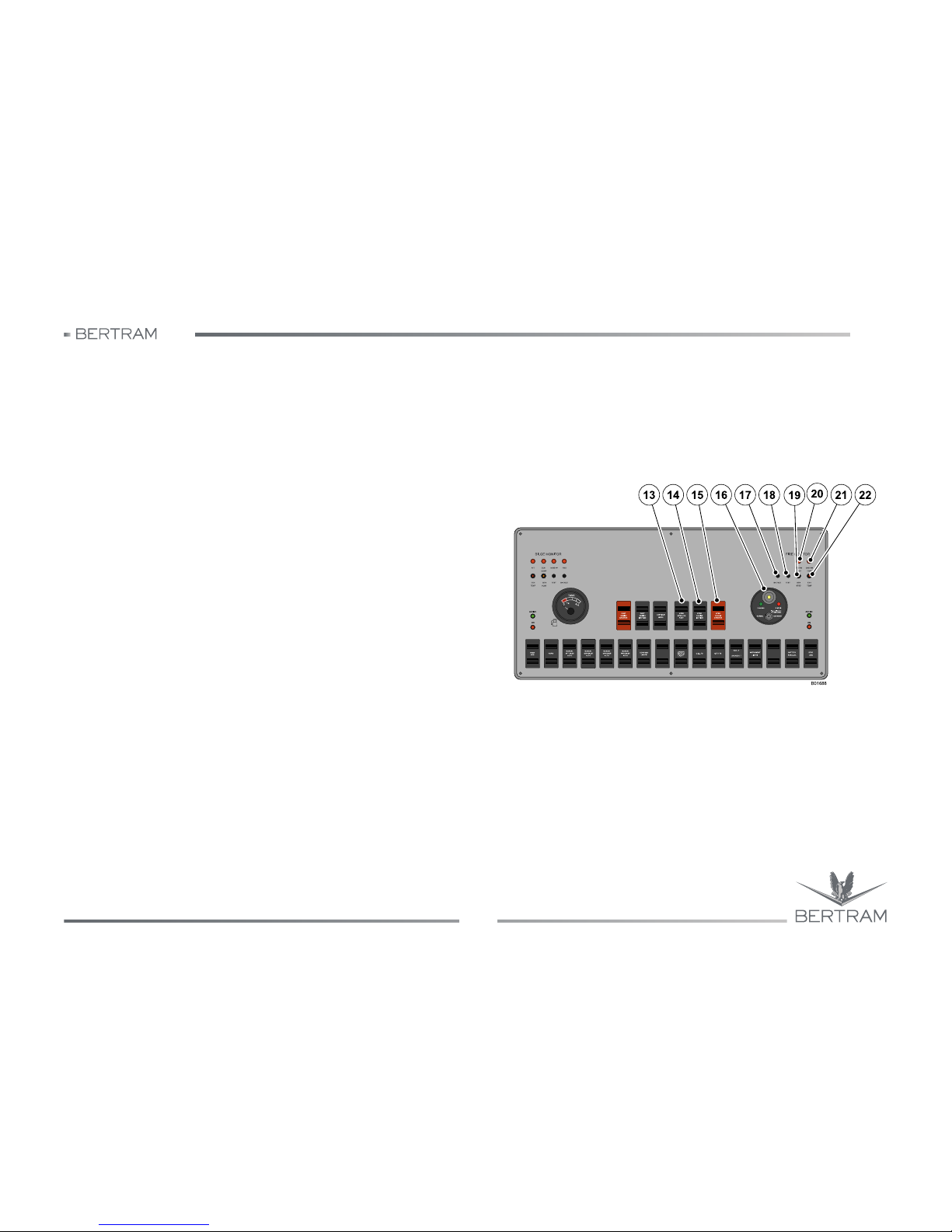
540
6
CONTROL STATION
Studio ti 03312 540-04usa
93
13. Engine synchronizer switch
This switch allows to activate the synchronization of both engines
and to use a one lever operation mode to control the engines.
14. Starboard ENGINE IGNITION switch
This switch allows to enable the start/stop of the starboard engine.
15. Starboard engine STOP/START switch
This switch enables to start/stop the starboard engine.
16. Fire-fighting alarm panel
This panel visualizes the warning lamps connected to the fire-fighting
system located in the engine room and it includes the OVERRIDE/
NORMAL switch.
17. Squelch button for firefighting alarm signal
This switch allows to disconnect the fire hazard signal buzzer.
18. Test button for high temperature signal
The test button is used to verify the correct operation of each signal
light of the panel. When using the test button, all LEDs must be ON
and the buzzer must sound to confirm the correct operation of the
signal system. When releasing the button all LEDs must go out and
the buzzer must clear off.
19. Starboard generator light
This light indicates that the starboard generator is running.
20. Generator room high temperature signal light
This light indicates that the temperature in the generator room is too
high.
21. Engineroom high temperature signal light
This light indicates that the temperature in the engineroom is too
high.
22. Starboard engine exhaust warning lamp
This light indicates high temperature inside of starboard engine
exhaust ducts.
Page 94
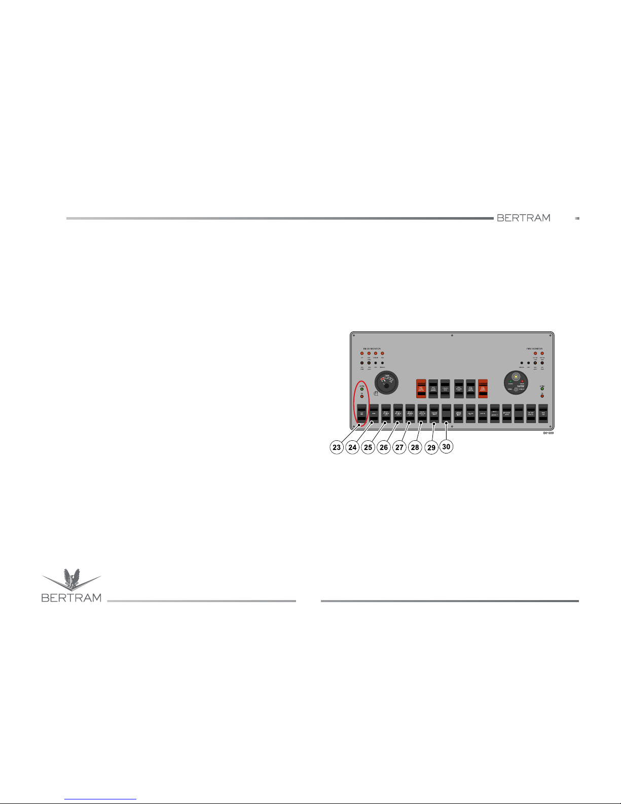
540
CONTROL STATION
Studio ti 03312 540-04usa
94
6
23. Port ARG Anti-Rolling-Gyro switch (optional)
This switch allows to activate the port ARG Anti-Rolling-Gyro.
• ON: indicates that the ARG is powered by the relevant circuit
breaker.
• ACTIVE: indicates that the ARG stabilizer has reached its operation
speed.
24. Horn switch
This switch enables the operation of the horn.
25. Stern bilge pump switch
This switch allows the manual activation of the stern bilge pump.
26. Generator room bilge pump switch
This switch allows the manual activation of the bilge pump in the
generator room.
27. Engineroom bilge pump switch
This switch allows the manual activation of the bilge pump in the
engineroom.
28. Bow bilge pump switch
This switch allows the manual activation of the bow bilge pump.
29. Switch for magnetic compass backlighting
Allows the backlighting of magnetic compass.
30. Available
Push-button available for auxiliary system.
Page 95
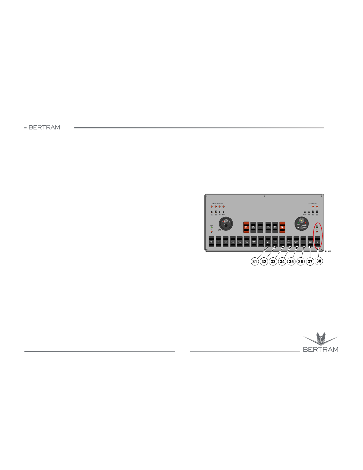
540
6
CONTROL STATION
Studio ti 03312 540-04usa
95
31. Underwater lights
This switch allows the activation of the underwater lights.
32. OVERHEAD lights
This switch allows the activation of the OVERHEAD lights.
33. Quartz light switch
This switch allows the activation of the quartz lights.
34. Anchor riding and navigation switch
This switch turns on the anchor riding or the navigation lights.
35. Instrument light switch
This switch turns on the instruments backlighting.
36. Available
Push-button available for auxiliary system.
37. Batteries parallel connection switch
This switch allows the parallel connection of the users/engines
batteries, in order to ensure more power at engines start. This switch
may be used only if the batteries are not sufficiently charged.
38. Starboard ARG Anti-Rolling-Gyro switch (optional)
This switch allows to activate the starboard ARG Anti-Rolling-Gyro.
• ON: indicates that the ARG is powered by the relevant circuit
breaker.
• ACTIVE: indicates that the ARG stabilizer has reached its operation
speed.
Page 96
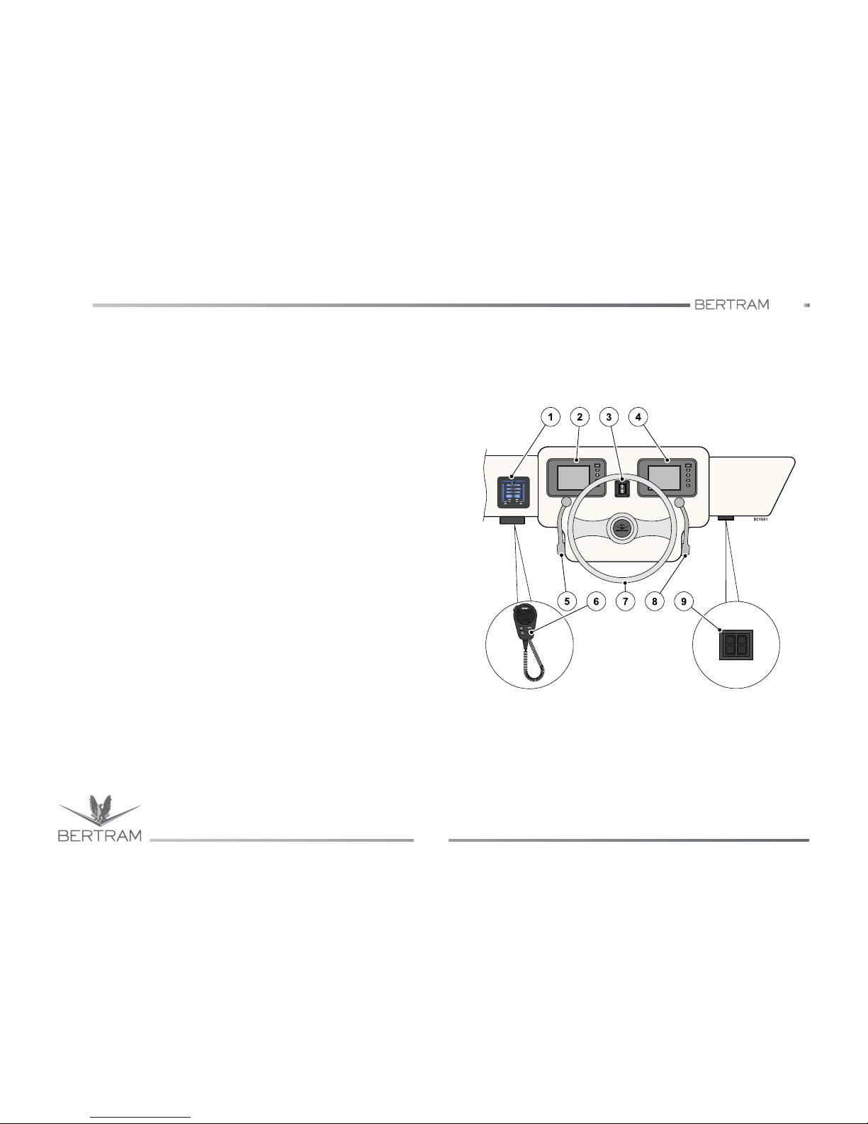
540
CONTROL STATION
Studio ti 03312 540-04usa
96
6
6.2.3 SECTION C - Control and maneuver heads
1. Control panel of gearboxes
This block monitors, by means of electric signals, the revolutions of
the propulsion engines and the speeds of the gearboxes.
2. Port engine control panel
This panel allows monitoring all operating parameters of the port
engine.
3. Anchor windlass switch
This switch allows the operation in both directions of the bow anchor
windlass.
4. Starboard engine control panel
This panel allows monitoring all operating parameters of the
starboard engine.
5. Starboard head (optional)
This head drives by means of an electric signal the revolutions of the
starboard engine and the gears of the starboard gearbox.
6. VHF-DSC microphone
VHF microphone with remote control function on channels and output
power.
7. Steering wheel
By turning the drive wheel you actuate an hydraulic pump that
operates the piston located in the helm gear compartment, this in turn
is connected to the rudder and allows to drive the yacht.
8. Port head (optional)
This head drives by means of an electric signal the port propulsion
engine revolutions and the port gearbox speeds.
9. Trim tabs control panel
This panel carries the switches for trim tabs activation.
Page 97
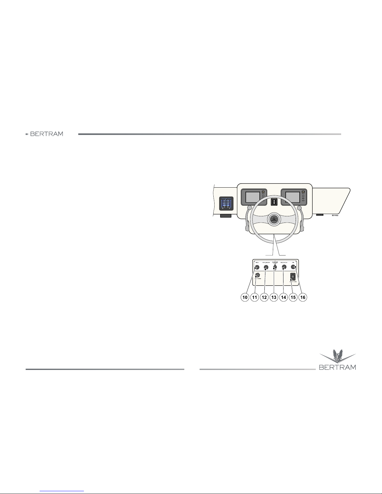
540
6
CONTROL STATION
Studio ti 03312 540-04usa
97
10. Bilge flood alarm signal
This signal activates to indicate a bilge flood hazard.
11. Cell-phone charge
It allows to charge the cell-phone.
12. Port exhaust signal buzzer
This buzzer activates to indicate an excessive temperature of
exhaust gases in the port engine.
13. Console switch
This switch allows the opening/closing of the console.
14. Starboard exhaust signal buzzer
This buzzer activates to indicate an excessive temperature of
exhaust gases in the starboard engine.
15. 12 V electric outlet
12 V DC socket
16. Fire hazard signal buzzer
This signal activates to indicate a fire hazard.
Page 98
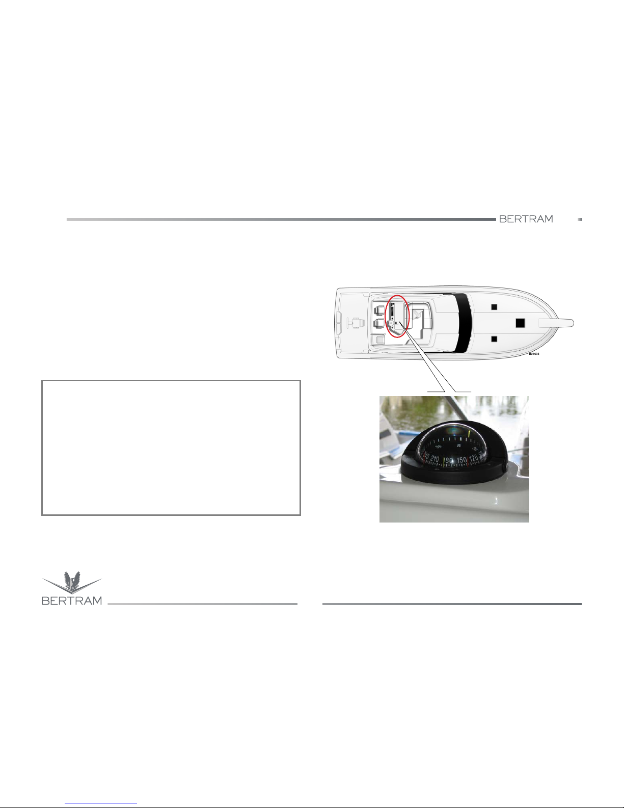
540
CONTROL STATION
Studio ti 03312 540-04usa
98
6
6.2.4 SECTION D - Magnetic compass
A magnetic compass fitted on the dashboard of a yacht is inevitably close
to the magnetic fields produced by the electric and electronic systems on
board. This condition is called “variation”. Only a skilled technician should
set the compass to correct the variation and supply an accurate deviation
schedule. This procedure is called “compass compensation” or “compass
setting”.
Compensate the compass after the yacht launch or when replacing it, in
order to eliminate possible mistakes due to the compass position.
Do not approach the compass to steel or iron objects or objects made of
other ferrous materials (e.g. tools, wrenches, batteries, etc.). The ferrous
materials close to the compass alter the readings and make them
unreliable. Remove any unnecessary object near the compass.
NOTICES
The compass delivered with the yacht is not compensated for change
or deviation. Any electrical or metallic item located in its proximity may
influence the compass. The yacht’s owner is responsible for the
compass compensation. Compensation should be carried out after
installing additional electronic equipment or once a year after a
prolonged period of mooring or ground lay-up. Compensation should be
carried out only by authorized and qualified personnel.
As a compass can rarely be set to zero variation on all courses, the
technician in charge of its compensation should give you a card
containing the corrections to be applied to navigation calculations.
Always keep this card available on the main control station.
Page 99
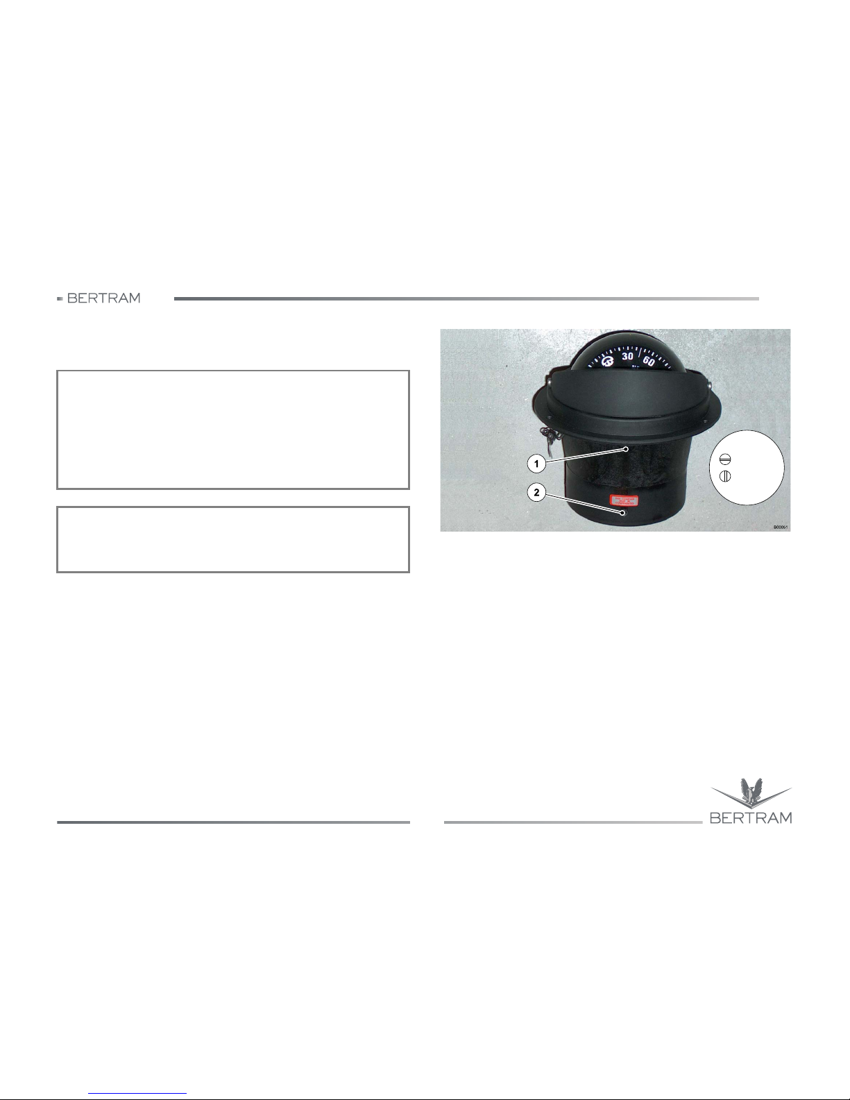
540
6
CONTROL STATION
Studio ti 03312 540-04usa
99
Compass compensation
Read carefully the manual delivered by the manufacturer.
Objects in the immediate vicinity influence every compass. Deviation is
the angular difference between the reading your compass provides as
installed and the reading it would provide if the objects were not there.
Deviation is expressed in degrees East or West of true North. It varies
with the heading of your vessel because, as your vessel turns, the
position of the objects that affect the compass change relative to the
magnetic North.
You must record deviation of the compass on a compass deviation card
and place it near the compass. You must record the deviation for each
individual compass that you use, because the position of each compass
relative to the materials around it determines the deviation.
You compass is fitted with a set of compensation, or adjustment, screws
to minimize these errors. It is seldom possible to compensate for all
compass deviation errors, since this type of error varies as the heading
of your vessel varies. However, the error should remain the same for any
given heading, as long as no changes are made to instruments and
electronic fixtures near the instrument panel.
There is a vertical mark on the compass called a “lubber line”. This line
was oriented when your compass was installed, so an imaginary line
drawn from the compass pivot point to the lubber line will be parallel to
the longitudinal axis of your vessel. Thus, your vessel’s course is the
compass card reading below the lubber line.
NOTICES
Never unscrew for any reason screws and filling caps (1). The only
screws that may be turned are the adjusting screws (2) by means of the
non-magnetic screwdriver provided. When the adjuster’s screw slot (2)
is horizontal, the compensation is neutral. When the slot is vertical, the
compensation is at its maximum. This operation must be carried out
only by a trained compass adjuster.
NOTICES
At least once a month check the operation and the deviations. If
necessary, have a new compensation of the compass turns carried out.
Neutral
Maximum
Page 100
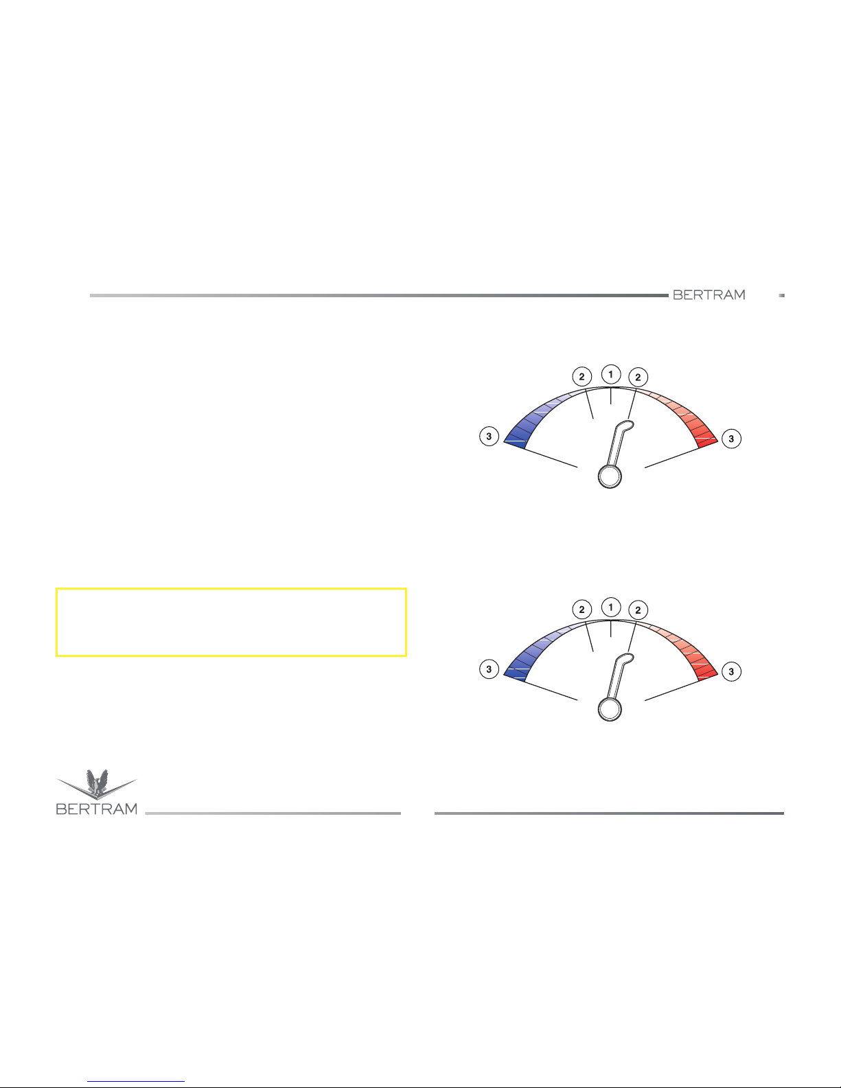
540
CONTROL STATION
Studio ti 03312 540-04usa
100
6
6.3 HANDLE BLOCK
The heads block is a system designed to control through electric signal
the revolutions of the engines and the gearbox speeds. The system may
consist of a single block carrying the heads and the selector switches or
of two separate heads, each one installed at the side of the drive wheel,
and of a separate panel.
In both cases the heads can be moved to three detents:
1. Neutral: in this position, the gearbox is disengaged and the
propulsion engines turn at idle speed (visual signal “N” lit);
2. Ahead/astern: in this position the gearbox is engaged to “ahead” or
“astern” gear and the engines turn at idle speed (visual lights “F” or
“R” lit);
3. Maximum revs: indicates the maximum speed detent for ahead and
astern gear.
The system between the positions (2) and (3) changes the engine
revolutions continuously.
The operation principle is different for the two modes: standard and
trolling.
S
CAUTION
In “trolling” mode (optional) the function of the heads block changes with
respect to the standard mode.
B00255
Standard mode diagram
infinitely variable speed
adjustment
full speed (full
speed astern)
ahead detent
full speed (full
speed ahead)
neutral detent
astern detent
infinitely variable speed
adjustment
backward
thrust range
thrust range
forward
B00255
Trolling mode diagram (optional)
infinitely variable slip
adjustment and speed
increase regulation
Clutch: 0% slip (grip) and max.
speed when trolling
gear box: clutch backward 100%
slip (lock)
neutral detent
infinitely variable slip
adjustment and speed
increase regulation
backward
thrust range
thrust range
forward
Clutch: 0% slip (grip) and max.
speed when trolling
gear box: clutch backward
100% slip (lock)
 Loading...