

Page 1
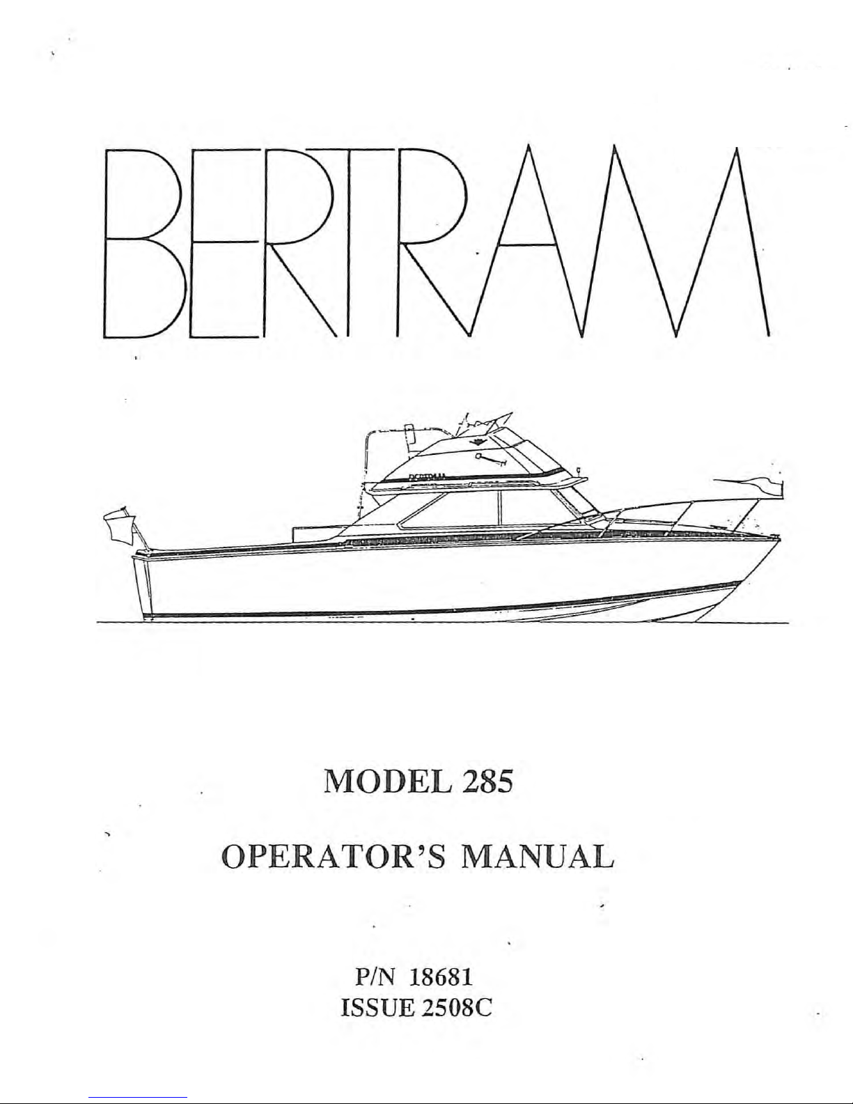
OPERATOR'S MANUAL
PIN 18681
ISSUE 2508C
Page 2

REVISION
AND
EFFECTIVITY
PAGE
REVISION EFFECTIVITY
:
====~~====l=========================:================
o
A
B
501
AND
January
July
1988
HULL
NUMBER
SUBSEQUENT
1987
~
-
ORIGINAL ISSUE
GENERAL
GENERAL
",.
CHANGES
==========1
CHANGES
UPDATE
Page 3

We
are
pleased
that
A
WORD
you
have
OF
WELCOME
chosen
a
Bertram,
and
know
that
its
unique
years
modern
quality
design
of
materials
standards.
inspected
As
durable
reasonable
maintenance,
to-time
for
containing
for
your
operating
will
boating
boat.
as
its
care.
adjustments,
certain
a
wealth
particular
condition.
give
you
pleasure.
and
is
manufactured
It
comes
construction
And,
as
components.
of
detailed
model
outstanding
Your
to
is
always
or
repairs
as
a
guide
Bertram
to
you
is,
as
your
true
may
Thus,
information,
for
performance
is
built
Bertram's
a
factory-tested
Bertram
with
be
required
this
Operator's
has
keeping
will
things
been
it
and
many
with
fine,
demanding
and
benefit
mechanical,
from
Manual,
prepared
in
good
by
time-
To
fully
To
this
any
Bertram
, When
has
points
your
been
enjoy
end,
arise
dealer
boat
factory
we
representatives
We
wish
you
many years
your
Bertram,
suggest
that
will
be
requires
trained
are
available
that .you
you
do
glad
service,
to
of
pleasurable
you
not
to
help
to
- i
should
read
completely
assist
contact
you
help
understand
this
you.
your
and
our
him
yachting
manual
understand,
Bertram
factory
if
need
on
it
completely.
thoroughly.
your
dealer.
service
be.
your
new
If
He
Bertrarr
Page 4

PREFACE
This
Table
section
manual
In
packets
1.
basic
2.
manual
of
covers
are
addition
of
The
mechanical
The
Contents,
12
users
manufacturers
equipment
is
divided
a
specific
the
recommended
to
this
information
Vdc
and
drawings.
manuals
of
the
components.
and
Section
manual,
:
the
and
major
into
system·
preventative
120
operating
mechanical,
sections.
B,
or
you
will
Vac
systems
Vessel
systems.
find
instructions
electrical,
Except
for
Technical
Included
maintenance
the
following
wiring
Section
Data,
schedules.
diagrams
supplied
and
A,
each
in
this
two
and
by
comfort
The
the
the
These
drawings
understanding
how
they
that
Each
by
some
service
appliance
manufacturers'
on-board
maintenance
scheduled
this
shooting
manual.
techniques,
procedures,
and
of
operate,
your
and
systems
which
maintenance
Section
and
other
manuals
the
equipment ·and
but
they
Bertram.,
major
piece
operating
and
is
not
discussed
is
discussed
G
also
Bertram
special
."~.~ll
will
not
be
of
and
maintenance
equipment
includes
recommended
maintenance
only
systems
invaluable
on-board
need
in
these
in
Section,G,
recommended
help
on
you
your
to
equipment
manuals.
scheduled
manuals.
storage
procedures.
to
get
a
better
Bertram
the
technicians
is
and
cov~red
However,
preventative
This
"MAINTENANCE"
trouble-
and
refloating
of
-
ii
-
Page 5

The
Bertram
Yacht
Company
HISTORY
is
widely
accepted
through
out
the
boating
in
the
although
started
'
Miami
Raymond
the
trials
Watching
with
that
the
this
radical
major
fraternity
world.
the
in
yacht
Hunt
that
smooth
design
break
inspiration
July
broker,
ferrying
for
performance,
24-foot
through
The
of
the
ride,
was
as
the
history
1958
watched
crews
America's
the
"Hunter"
a
full-length,
in
boat
number
of
for
when
the
Richard
a
24-foot
and
Cup
Richard
ease
demonstrated
design.
one
Bertram
Bertram
sails
Race.
Bertram
of
maneuvering,
deep
pleasure
Yacht
yacht
Bertram,
tender
around
in
"V"
Richard
dates
a
designed
the
was
the
hull
Bertram
boat
line
highly
harbor
very
and
heavy
and
manufacturer
back
to
actually
successful
by
C.
during
impressed
the
stability
seas.
it
was
recognized
1960,
This
a
this
hull
and
design
completed
Even
though
racing
Bertram
Race.
driver
won
this
so
severe
day.
This
public
commissioned
in
in
1960.
this
boat,
she
entered
With
Sam
Richard
Griffith
race
that
surprising
that
a
deep
the
31-footer
performed
her
in
record
only
Hunt
form
in
Bertram
as
one
victory
"V"
hull
of
the
crew,
time
other
to
design
a
wooden
was
never
so
well
1960
as
Miami
the
"Moppie"
under
boat
demonstrated
design
and
31-footer
intended
on
her
to
pilot
,
named
boating
even
could
build
shakedown
Nassau
and
veteran
after
conditions
finished
to
plane
a
which
to
Ocean
the
an
amazed
and
similarly
was
be
an
cruise
Powerboat
race
Mrs.
that
race
still
shaped
to
be
ocean
that
boat
Bertram,
were
that
boating
maintain
-
iii
-
Page 6

high
speeds
in
rough
seas.
Richard
Bertram
recognized
the
possi-
bilities
and
reputation
The
new
innovative
aluminum
used
a
a
first
the
mold
relatively
model
National
With
manufacturing
of
hull
designs
dominated
hull
to
build
Boat
this
Hunt
behind
design
of
his
his
new
material
31-footer
Show.
designed
the
was
and
materials.
the
boat
victorious
new
was
A
year's
of
the
newly
just
boat
to
the
31-footer
hull
formed
the
beginning
building
31-footer
from
the
pleasure
sensation
production
and
At
fiber
well
Bertram
Bertram
a
time
industry,
as
reinforced
boating
of
was
under
of
the
Yacht
a
when
Richard
a
plug
1961
sold
way
put
long
wood,
plastic
industry.
out
and
his
resources
Company.
list
steel,
Bertram
to
construct
New
York
in
advance.
several
of
and
(FRP)
This
additional
Company
of
1962,
present
became
a
location,
Airport.
In
1968,
the
interests
recreational
support,
pleasure
interest
Bertram
boat
in
manufacturing
models
new
California
in
metals,
products,
Bertram
operations.
on
the
drawing
a
division
of
manufacturini"facility
about
one
based
chemicals,
acquired
was
industry.
able
Yacht
to
In
along
Today,
the
mile
Whittaker
science,
Bertram
expand
March
with
boards,
Nautec
east
and
of
1985,
other
Bertram
the
Corporation.
was
of
completed
the
Corporation,
technology,
Yacht.
become
Whittaker
marine
Yacht
Bertram
Miami
With
a
leader
related
is
Yacht
In
November
at
Bertram's
International
with
and
Whittaker's
in
sold
a
division
their
the
of
Bertram-Trojan,
in
length.
Inc.
and
manufactures
models
-
iv
-
from
28
to
54
feet
Page 7

Since
1961,
most
of
Bertram's
boat
construction
experience
has
been
in
However,
military
Bertram
and
Bertram
products.
company
phy
is
maintain
hull
performance.
material
have
been
making
Bertram
power
power
has
While
has
built
that
this
the
enthusiasm
applications
applied
the
has
boats
boats
continued
not
racing
continued
to
highest
also
for
are
currently
The
results
research,
Bertram's
built
many
a
product
its
hulls
and
quality
a
foreign
dedication
active
for
exposure
motivation
of
and
primary
recreational
variety
and. domestic
of
offshore
on
others.
to
racing
in
the
continuing
construction
products.
of
to
the
the
power
commercial
power
high
performance
racing
The
Bertram
has
design
design
methods
boats.
customers.
boat
circuit,
been
one
areas
and
racing
this
philoso-
way
of
research,
research
to
One
conservative
one
superstructures
first
on
fiberglass
,
commercial
of
fiberglass
company
of
of
in
the
the
to
this
v
make
engineering
engineering
early
users
beginning
industry
boats.
essels.
fuel
tanks
its
and
of
to
This
Bertram
own
aluminum
"design
oriented
balsa
in
1965.
use
was
was
and
was
areas
company
core
Bertram
aluminum
used
on
also
also
window
where
has
construction
was
decks
the
first
the
and
58-foot
in
first
frames.
this
led
basically
the
in
also
superstructure
yacht
the
design
production
way
decks
one
was
of
and
and
as
and
the
on
use
boat
- v -
Page 8

FOREWORD
This
experience
classes
Power
aspects
,aware
the
alert
passengers,
items
manual
Squadron.
of.
Throughout
form
you
carefully.
or
taught
of
safe
ot
to
is
not
even
by
We
boating
WARNINGS, CAUTIONS,
this
warnings,
possible
and/or
The
intended
one
the
U.
included
manual
cautions,
dangers
to
your
mere
of
S.
that
to
replace
the
several
Coast
some
a
careful
you
to
vessel.
existence
Guard
material
will
and
notes
yourself,
Read
years
excellent
Auxiliary
boat
AND
find
these
of
a
ot
relative
operator
NOTES
special
that
warning
the
are
crew
special
boating
sate
boating
and
to
should
information
intended
or
information
or
a
the
U.
certain
caution
S.
be
in
to
note
dangers.
"good
wi
thin
seamanship"
~*****************~******************************
*************************************************
*************************************************
•
a
box
Your
FAILURE
DEATH
close
of
are
TO
OR
asteri.:s.~s
attention
the
major
WARNING:
HEED A WARNING
SERIOUS
will
to'the
accident
INJURY.
CAUTION
not
by i tselt
instructions,
prevention
MAY
RESULT
eliminate
IN
•
•
•
Failure
injury
to
and/or
heed
a CAUTION'
damage
to
the
may
vessel.
result
in
•
plus
measures.
basic
•
•
•
*
*
*
*
•
•
the
vi
Page 9

NOTE:
Notes
important
We
pieces
wish
are
in
you
Bertram.
GETTING ACQUAINTED
The
to
stuffing
system.
switch
three
the
aft
and
hatches
bilge.
boxes,
The
optional
the
and
bilge
boldface
of
information.
many
years
WITH
in
the
The
the
aft
flood
.
type
of
YOUR
BERTRAM
THE
cockpit
aft
bilge
components
bilge
alarm
and
are
pleasurable
MODEL
COCKPIT
sole
at
contains
of
the
pump
and
switch
intended
yachting
285
the
stern
the
rudder
hydraulic
its
automatic
(mounted
to
stress
on
your
new
FLYBRIDGE CRUISER
provide
access
post,
steering
float
higher
than
the
bilge
fuel
port
the
On
cover.
pump)
gauge
and
propeller
each
storage
Over each
the
spaces
over
each
engines.
are
sender,
starboard
side
The
shoreline
locker.
engine
outboard
engine.
accessible
shaft
of
the
is
an
fuel
hatch
log
cockpit
is
THE
a
hinged
of
each
access
through
supply
fittings,
aft-of
stuffing
is
a
permanently
ENGINE
hatch
engine
hatch
-
vii
the
center
and
the
motor
boxes
storage
boxes
and
space
connected
COMPARTMENT
for
access
.
In
addition
is
provided
-
the
their
to
between
hatch,
trim
provide
sprayshields.
with
in
the
the
to
the
as
tab
a
sliding
port
engines
hatch
the
is
the
pump.
access
side
A
to
and
Page 10

The
center
hatch
provides
access
to
the
battery
disconnect
switches
bulkhead.
condenser
seacock,
compartment
The
end
fuel
engines
the
engine-compartment
the
midship
of
the
valves
.
garboard
compartment.
and
strainer
The
is
fuse
optional
in
the
panel
engine-compartment
and
bulkhead.
bilge
flood
engine-compartment.
to
control
The
seacocks
hull
drain
mounted
air
pump
sump
alarm
the
and
are
on
conditioning
are
just
pump,
switch
There
fuel
supply
seawater
in
the
the
aft
its
are
strainers
aft
forward
system
on
the
of
the
automatic
located
are
also
to
their
end
of
engine-compartment
sea-water
port
forward
float
at
port
side.
switch,
the
and
cooled
The
engine-
forward
starboard
respective
for
the
each
engine-
engine
Ale
and
and
The
fixed
Halon
engine-compartment
system
The
port
exhaust
starboard
They
depending
(battery
The
The
is
head
engine.
may
toilet
"Y"
located
exhaust
blowers
batteries
be
relocated
on
charger)
holding
control
the
fire
bulkhead.
under
blower
Outboard
which
are
options
is
tank
v
alve
extingu"isher
.-
The
the
forward
is
mounted
of
the
engines
ventilate
located
to
provide
selected.
located
is
that
outboard
located
allows
cylinder
" "I·
supply
end
on
the
bilge
outboard
better
The
outboard
you
of
the
are
weight
optional
of
to
is
seacock
the
bulkhead
the
area.
of
the
the
starboard
of
select
mounted
for
starboard
forward
port
and
The
port
engine.
distribution,
converter
the
port
on
the
starboard
port
engine.
engine.
the
aft
toilet
engine.
of
and
the
-
viii
-
Page 11

where
the
toilet
empties,
(the
holding
tank
or
directly
overboard)
the
holding
For
additional
Section
The
flybridge
height
The
engine
switches
the
helm.
helm.
of
facing
are
The
and
tank
this
control
the
gauge
mounted
The
trim
the
manual
and
accessible
information
manual.
THE
control
panel,
on
throttles
tab
controls
overboard
see
FLYBRIDGE
station
console
twin
the
and
tachometers,
flybridge
gear
and
through
"Toilets"
CONTROL
has
a
with
shifts
the
discharge
the
in
STATION
helm
seat
its
control
are
alarm
port
the
built-in
and
on
panel
pump
are
engine
Mechanical
adjustable
footrest
the
system
console
each
are
forward
hatch.
for
control
forward
side
of
mounted
of
.
of
the
on
the
panel.
"electronics"
and
navigation
Forward·of
bilge
,
pump
accessible
and
its
(mounted
control
Inside
pump
is
under
automatic
panel
the
access
through
higher)
as
a
storage
distribution
equipment
lower
step
hatches
the
cabin
the
float
are
accessible
is
THE
sole
aft
switch
the
Halon
sp~~e,
panel
that
you
fire
in
that
choose
CABIN INTERIOR
with
.
The
its
shower
between
cabin
and
hatch.
the
through
extinguisher
the
console,
powers
built-in
and
the
bilge
to
water
The
the
the
have
storage
air
forward
flood
forward
monitor
is
the
12
communications
on your
space
conditioner
tanks
and
bilge
alarm
bilge
Vdc
vessel.
are
sump
is
pump
switch
access
two
hatch.
-
ix
-
Page 12

The
fresh
water
tank
is
located
just
forward
of
the
forward
engine-compartment
located
side.
enclosed
If
your
~vaporator
The
dinette
lowered,
double
the
forward
120
VAC
in
Water
in
boat
and
bed.
outlets
a
locker
is
the
has
and
table
a
Access
storage
bulkhead.
heated
galley
the
controls
has
filler
to
locker.
are
provided
aft
of
by
cabinet
optional
are
a ·
movable
cushion
the
the
a
rope
The
"Vee" berth
120
Vac
below
air
built
leg
is
provided
locker
in
the
fresh
water
shore-power,
the
stove
conditioning
into
that
the
permits
to
is
provided
galley,
system
bulkhead
water
area.
system,
deckhouse
it
convert
the
head
pump
on
heater
the
overhead.
to
be
it
by
doors
(toilet),
the
to
is
port
a
on
the
The
Ilvee
The
seat,
dinette,
12
Vdc
ll
berth
120
Vac
facing
and
the
distribution
area.
distribution
inboard.
face
of
panel
panel
the
is
is
starboard
located,
located
"vee"
to
starboard,
in
the
berth
aft
.
in
dinette
the
- x -
Page 13

TABLE
OF
CONTENTS.
Dealer
Title
Revision
Preface
Foreword
Table
A.
B.
of
VESSEL TECHNICAL
MAIN
Evaluation
Page
Page
Contents
ENGINES
Card
.....
....
FRONT
A.
........
B.
TECHNICAL
DATA ..............
..
...
...
MATTER
CONTENTS
. .......
SECTION
......................
DATA
SECTION
........................
......
........
..
.
......
. . . .
A-1
B-1
B-2
C.
D.
E.
F.
G.
H.
I.
J.
ENGINE
PROPELLERS
BATTERIES
...........
PROPELLER SHAFTS
FUEL
Table
VENTILATION
BILGE
HOLDING
PERFORMANCE
REMAINING
B-1,
Fuel
AND
AND
SUMP
TANK
CAPACITY
CHARTS
.......................................
-:.:
...
.. _ ..
.-
" I
.... _ ..........
................................
IN
TANKS
............
-.
Readings
EXHAUST
PUMPS
...................................
............
BLOWERS
.........
Vs
Tank
..............
.
........................
......
..
. .
......
Gallonage
.. ...........
. . _
_ .......
.............
...
....
..
....
.....
..
...
....
..
..
..
B-2
B-2
B-3
B-3
B-3
B-3
B-4
B-4
B-4
A-1
Page 14

C.
CONTROLS
AND
INSTRUMENTS
SECTION
A.
B.
SWITCHES
1.
2.
3.
4.
5.
6.
7.
....
Battery
Before
Starting
Battery
After
Stopping
Accessory
INSTRUMENTS
1.
2.
3.
The
Importance
Oil
Pressure
Temperature
Power
Starting
Engine
Paralleling
Engine
Engine
Switches
...........
....
Starts
....
of
Gauge
Gauge
.
...............................
Engine
..
....
....
...........
Switch
..........................
....
.
..... .....................
..........
....
.....................
Instruments
................................
............................
,
......................
.
...
........................
.
.................
...............
.
.............
...
.
.
..
'"
.....
.....
.
....
....
...
C-l
C-l
C-l
C-1
C-2
C-2
C-2
.C-3
C-4
C-4
C-4
C-5
C.
4.
5.
6.
7.
ALARM
1.
2.
3.
4.
D.
MECHANICAL CONTROLS
1 .
2.
Tachometer
Hour
Voltmeter
Fuel
SYSTEMS . . . .
::ngine
Bilge
Fire
Fire
Alarm
and
Engine
Steering
Meter
Gauge
alarms
Alarm
Speed
..................
.................
......
..................
...
...
Switches
Switches
Bilge
and
System
.
. ' . . ' .'
alarm
...
. . .
.....
. .
...
. .
.
..............
Marine
...
.
..
..........
. ; . '
.......
...
.........................
..........................
...
.....
.....
Lights
Gear
. . . . .
........ ....
.
.......
.............
Controls....
..
. . . . . . . . .
.....................
...
..
.......•..
.............
.
...............
.
.......
..
......
...
.
. .
........
. .
..
.'
.......
.
. .
..
. . . . .
. . .
.....
...
.
....
....
... C-9
. .
..
C-5
C-6
C-6
C-6
C-7
C-7
C-8
C-9
C-9
C-9
C-I0
3.
Trim
Tabs.........
A-2
. . .
.......
..
.........
. . .....
. .
C-I0
Page 15

D. VESSEL OPERATIONS
AND
SAFETY
AFLOAT
A. VESSEL SAFETy .......
B.
C.
D.
E.
F .
G.
1.
2.
3.
CARBON
THE
WHEN
PROPELLER
ALCOHOL
THE
1.
2.
Fueling
Before
After
MONOXIDE
FISHING
UNDERWAy
HAZARD .....
STOVE
FIRE
WARNING
General
The
Fire
Instructions
Fueling
Fueling
TOWER
.................
FLARE-UP
......................................
and
. . . . .
GAS
. .
AND
Bilge
..
.......
......
...
...
. ............
......
.....
...................
THE
Flood
..
........
.
.....
. :
............................
....
.
.....
......... ' ..
.
....
. .
......
; . . ........
..
...........
FIRE
EXTINGUISHING SYSTEMS
Alarm
..
....
.......
..
.........
.
.....
Systems
.....
.
......
...
..
. .
..
....
.
.............
.......... D-6
.
.......
...
........
.....
......
...
. .....
..
.....
. .... .
. .
.
.. ..
....
...
..
..
.
D-l
D-l
D-2
D-2
D-3
D-5
D-5
D-7
D-7
D-7
D-8
....
H.
I.
J.
K.
L.
3.
4.
5.
6.
7.
8.
'
THE
FIRE
THE
FIRE
THE
THE
USE
RING
RADIOS
The
Fixed
Moni
tor
The
Portable
The
Halon
System
After
the
System
Inspection
FIGHTING
OR
EMERGENCY
OF
PERSONAL
BOUY
AS
EMERGENCY
Fire
System
Fire
1301
Function.'
Fixed
Discharge
and
PLAN
...
..
......
Extinguisher
..•
,'
..
' .
.............
Exd.riguishers
Fixed
..
Fire
. .
Fire
...
...............................
Extinguisher
..................
Restarting
........
EVACUATION
Discharged
...........
Extinguisher
Vessel
..
...............
PLAN ........
FLOATATION DEVICES
. .
......
EQUIPMENT
' .
....
..................
..
..
.
Systems
...
' . .
. .
...
...
..
......
.
.......
System ....
.....
.
......
..
...
.
.......
......
....
...
..
. ....
..
......
......
..
....
...
..
...
..
D-9
D-9
D-ll
D-12
:D-13
D-14
D-15
D-16
D-17
D-19
D-19
M.
MANEUVERING ... ..
......
.
..
..
.........
.
...
. . .
....
. . .
.....
D-
19
A
-3
Page 16

N. SINGLE ENGINE RUNNING .....
..
........
.....
..
0 0
••••
0 • • 0
••
0-20
O.
P.
Q.
R.
S.
T.
~.
DAMAGED
VESSEL SPEED
RUNNING
RECOMMENDATIONS
FLOTSAM
VIBRATIONS
TOWING
1.
2.
V.
1'1
X.
NAVIGATION
• VISUAL
SOUNO
UNDERWATER
EqUIPMENT
..................
AGROUND
(Floating
....
..................................
FOR
REFLOAT!NG VESSEL
Oebris)
............................
..................
.................................................
General
Personal
DISTRESS
SIGNALS ...
....
and
..........
Safety
RUNNING
SIGNALS
...........
....
. ........................
LIGHTS
................................
.............
.
...
..
........
...............
.
..................
.......
.......
.................
..
....
.
.............
.....
.. .........
..
...
. .
....
.
.....
..
...
.
.........
.
.....
..
...
.....
. .
...
.....
... 0-29
0-20
0-21
0-22
0-23
0-25
.
0-25
D-25
0-26
0-26
0-27
0-28
Y. CALLING
Z.
AA.
LEAVING
HULL
AT
PORTS
YOUR
BERTRAM ........
EFFICIENCy ....
BB. ATMOSPHERIC CONDITIONS
CC.
00.
EE.
FF . HEIGHT ...
GG.
;,
HH.
MARINE
I-IATER
DRAFT
GROWTH
IN
THE
.....
.....
..................................
TRIP
Before
PREPARATION
Leaving
?REPARATIONS
Heavy
Weather
.....................
BILGE
.
..............
...........
Oockside
FOR
ROUGH
Check
AWAY
...
....
List
FROM
~
.....
.\ ..
.
HOME
':'
........
.'
. ...........
.........
......
Checkoff
........................
.
...
..............
.
.......................
,
.
...........
.
.............
.
...
..
.....
Sheet
.....
WEATHER ...........•.........
...
....
. :
....
....
................
.
........
.
........
..
...
..
. .
...
...
..
............
...........
......
.
...........
. .
...
.
.....
.....
....
0-29
0-29
0-30
0-31
D-31
0-31
1)-
....
0-32
0-32
.
0-33
.... 0-3
0-35
32
4
II.
A
-4
TH
E BEAUFORT S
Table
0-1, The
CALE
Beaufort
OF
WINO
Scale
FORCE
of
.....................
Wind
Force
.......
. .
...
..
0-36
0-37
Page 17

E.
'
ELECTRICAL
SYSTEMS
A.
B. E
C.
D.
E.
GENERAL ...
LECTRICAL
GROUND
1 .
2 .
12
VDC
1.
2.
3 .
4.
120
1 .
AND
Bonding ...
Electrolysis
SySTEM
Batteries
Battery
Distribution
Automatic
VAC
SySTEM ......
Shore
.. ..
. .
............
DISTRIBUTIO
BONDING
, . .... . ....
. •
.......
.......
Switches
.......
Converter
Power
."
N·
PANELS
SySTEM
.......
..
.................
•
.............•...•
......
. . .
.............
....
. . .
..
. .
.....
..
..........
.....
.•
· . .
................
....
. .............
, .
.....
...
......
.
.....
....
.
.
..................
............•.
•
.....
. . .
................
..
.........
.
.............
. .........
.... . .... . .
...
. . . .
.......
..
........
. . .
. .
.•
•...
.
.....
.........
..
.
.
.
...
. .....••.
..
. .
....
.•.... E-4
.......... E-4
....
.....
.
....
. . .
...
...
E-l
E-l
E-l
E-l
E-2
E-2
E-2
E-2
E-3
E-4
F .
2 .
3.
4 .
CIRCUIT
Distribution
Galvanic
European
BREAK
Isolator
Shore
ERS
..............•......••...........
..
' . .
......
and
Power
FUSES
(Optional)
....
..... ...... , ..
•
..............
.........
.
.. ..
..........
. .... . . .
.
...
E-5
...
E-6
E-S
...
E-9
,
A
-5
Page 18

F.
MECHANICAL
SYSTEMS
SECTION
A·.
B.
FUEL
l.
2 .
3 .
4.
5.
SySTEM
The
Fuel
Fuel
Fuel
Type
PROPULSION
1.
2.
3.
4.
5.
Engines
Marine
Propeller
Propellers
Engine
...........................................
Fue 1 Tank
Vent
Supply
Filters
of
Fuel
SySTEM
.....
Gears
Shaft
...
.
.........
and
Fill
Lines
.................................
......................................
......................................
......................................
.
..............................
..
................
Shafts
.....
..
.....
Alignment
...
..
................................
............
..................
..
........
....................
..............
...............
......
.
.............
.
. .
.....
......
......
.
...
...
F-l
F-l
F-1
F-1
F-l
F-2
F-2
F-2
F-3
F-3
F-3
F-4
6.
7.
8.
9.
C.
D.
E.
TOILET
BILGE
FRESH WATER
1.
\
2.
3.
4.
5.
Shaft
Shaft
Rudder
Installat
SYSTEMS
PUMPS
Tanks
Filling
Water
Water
Shower
Log
Log
.......
and
Stuffing
Spraysh~_~.~d
Stuff
ion
ing
of
.......
.....................................
SySTEM
.......
.............
Box
... '-.. ' ..........................
Propellers
'.'
..................................
.
.............................
.......................................•...
the
Heater
Pump
Tanks
.
...........
.....................
.................
.....................
Box
...
....
.................
.....
................
.
:
......
.
............
.
..........
.
.....
..................
.
........
...
.
.. · ..
.......
.
.
......
......
...
...
...
..
F-5
F-6
F-7
F-7
F-9
F-lO
F-1l
F-ll
F-11
F-12
F-12
F-12
6 .
7.
Shower
Dockside
Sump
A-6
Water
Pump
Supply
.......................
(Optional)
............
...
.....
...
F-13
.
....
.
F-13
Page 19

F.
AIR
CONDITIONING
SYSTEM
(Optional)
................
.... .
F-13
A.
1.
2.
3.
Basic
Operating
Thermostat
PREVENTATIVE
1.
2.
3.
Periodic
Daily
Every
a .
b .
c.
d .
................
Exterior
Inter
V-Berth
Head
Instructions
Instructions
...........
G.
MAINTENANCE
Maintenance
100
Hours
..
............................
....
' ...
MAINTENANCE
.................
..............................
.
......
or
60
Days
...
..
............
ior .....................................
.....
..........................•.......
...
.................
.
...............
....
SECTION
.......
.
.....
.
...................
..
..
.
..........
............
....
.......
.
............
..
........
.
......
.....
....
...
.
...
. .
. .
..
. .
...
....
F-13
F-13
F-15
G-1
G-1
G-l
G-2
G-2
G-2
G-3
G-3
B.
e.
f.
g.
h.
4.
5.
6.
As
Crevice
Electrolysis
STORING
1.
2.
3.
4.
Dry
Wet
Fitting
Prelaunch
Galley .....
Engine-Compartme'nt
Lazarette
Flybridge
Required
............
Corrosion
. .
YOUR BERTRAM
Storage
Storage.
Out
.
. .
and
..........
:
.....
..........
Postlaunch
~:
. .
......
Control
...
....
.......
.. '
....
.....
.
..........................
. . .
..........
Station
...
.
.........................
..
...........................
..
...........
..
......
.
.....
...
.
..........
Checks
. . . .
...
..........
.....
.
.....
....
. .
.
......
..
.
..................
. . . .
....
..
..
....
......
...........
. .
...........
. .
...
..
......
.
.....
....
.
.....
....
..........
... .... G-9
.
....
...
... G-6
.
...
... G-7
.
.
...
G-3
G-4
G-6
G-6
G-7
G-7
G-7
G-9
G-9
a.
Prelaunch
...
.
.........
....
...........
.
......
.
G-10
A-7
Page 20

b.
Postlaunch
.....
.
....
.
.
.............
G-10
C.
c.
d.
e.
APPEARANCE
1.
2.
3.
4.
5.
6.
7.
8.
Care
Seasonal
Loss
Stains
Scratches
Bottom
Painting
Battery
Electrical
Engine
Controls
AND
of
CARE ...
Fiberglass
Care
of
Gloss
...................
and
Blisters
Fiberglass
Care
Check
Check
system
....................
. ....
check
..........................
..................................
......
(at
fitting
.....
...
Abrasions
...
...
.
............
out
......
.
....
........................
...
..
........................
Surfaces
..................................
..................
time)
..
.......
.
....
. .
............
.
....
..
.....
...............
.
..........
..
..........
....
........
.
.....
.
.
.
........
.. ..
..
..
..
G-11
G-11
G-11
G-12
G-12
G-12
G-12
G-13
G-13
G-14
G-15
G-16
9.
10.
a.
b.
c.
d.
e.
Spilled
a.
b.
c .
Fuel
Battery
Excessive
Maximum
Cleaning
Battery
Battery
Acid
Acid
the
If
splashed
splashed
clothing,
a
considerable
spilled
Tank
Replacement
Water
Loss
Charge
Batteries
Gases
Acids
from
..........................
of
Liquid
".
Vol
tage
.'
.............
,
........
- EXPLOSIVE
...... ..
in
the
eye
on
or
other
parts
parts
of
amount
the
battery
.............
.......
......
.
...
........ , ..
..........
..............
..............
of
the
your
of
acid
vessel
is
..............
. . . . ....
........
.
.........
.
.........
bod
........
...... G-16
..
G-17
...
G-18
G-18
.
...
... G-19
..... ..
G-19
y ,
G-19
..
.....
.. ..
G-19
G-19
G-17
a.
b.
Fuel
New
A-8
Tank
Tank
Removal
In
stallation
...................
.....
.
........
.
.
...
........
... ...
G-19
G-20
Page 21

A. VESSEL TECHNICAL
DATA
MODEL
BOAT
OWNER'S
OWNER'S
HAILING
285
NAME
NAME
ADDRESS
PORT
HULL
TONNAGE
(A
Volume
GROSS
NET
=
NUMBER
LENGTH
FUEL
WATER
MEASUREMENT
10.19
=
8.15
Unit
of
DOO~J{EY
OVERALL
DRAFT
CAPACITY
CAPACITY
Measure)
NUMBER
'28'
=
BEAM = 11
,-
3
240
=
50
=
Full
pounds
fuel
Feet,
Feet,
feet,
U.S.
U.s.
of
&
gear
REGISTRATION
6
Inches
0
Inches
0
inches
Gallons
Gallons
DISPLACEMENT
(In
POUnds)
water,
=
11,980
2
people,&
NUMBER
250
B-1
Page 22

B.
MAIN
ENGINES
Manufacturer
Model
Lube
Serial
Gear
C.
STANDARD
Number
Oil
Number
Serial
ENGINE BATTERIES
=
MerCuriser
=
5.7/260
Filter
PORT ENGINE
Number
BATTERY:
Manufacturer
=
=
Fuel
Filter
and
Gear
Gear
Primary
Element
STARBOARD
Serial
Gear
Manufacturer
Model
Gear
Number
Ratio
Number
Number
ENGINE
Number
Serial
=
=
=
=Mercury
=
=
Number
Borg-Warner
10-17-006
1.52:1
35-60494
QuickSilver
=
14957
Manufacturer
Voltage
OPTIONAL BATTERY:
Manufacturer
Voltage
D . PROPELLERS
Manufacturer
Diameter
Material
Port
Starboard
=
Deka
=
12
=
surrette
=
12
=
Dymex
=
17
=
Bronze
Rotation
Rotation
Volts
Volts
inches;
=
=
Right
Left
Style
Hand
Hand
Model
.'
Model
pitch
(Bertram
(Bertram
Number
Capacity
Number
Caoacity
=
3-Blade
=
16
Part
Part
=
MO-427
=
75
Ampere
=
T-12-135
=
120
Ampere
17x16xl-1/4
Number
Number
hours
hours
cup
08455)
08456)
B-2
Page 23

E.
PROPELLER SHAFTS
Material
Length
F.
FUEL
Table
the
approximate
in
the
l=========================:=====================================
~----------------------------,--------------------------------------------
B-1
tank.
TABLE
Gauge
=
Stainless
=
63-1/2
shows
Full
3/4
1/2
the
number
B~l.
Reading
steel
inches
relationship
of
FUEL
gallons
GAUGE
J" •
••
Bertram
of
the
(fuel
READINGS
Diameter
Part
fuel
tank
Vs
TANK
Forward
240
gallons
167
gallons
79
gallons
Number
gauge
label
GALLONAGE
Tank
=
1-1/4
=
OBD5616-6
indication
capacity)
*
•
•
inches
and
of
fuel
1/4
Empty
*
Usable
capacity
fuel
.
is
G. VENTILATION
ENGINE-COMPARTMENT
HEAT
REMOVAL
BLOWERS
considered
And
EXHAUST
= Two
to
BLOWERS
(2)
130
controlled.
31
o
be
90%
of
the
CFM,12-Voltd.c.
gallons
gallons
fuel
•
tank
label
,manually
B-3
Page 24

H. BILGE
AND
SUMP
PUMPS
?UMP
I.
J.
?erformance
are
bottom
installation
RATED
HOLDING
PERFORMANCE
taken
and
CAPACITIES
Engine
Shower
TANK
data
on
a
10
to
of
Room
CHARTS
(SPEED,
new
12
certain
Bilge
Sump
sump
CAPACITY:
test
foot
Pumps
Pump
[:lump
RANGE,
boat
water
options
11
under
1,750
=
=
=
800
700
Gallons
and
depth.
(i.e.,
FUEL
ideal
Gallons
Gallons
Gallons
(in
conditions,
Factors
a
tuna
per
per
per
gallons
such
tower),
Hour
Hour
Hour
per
with
as:
the
boat
hour])
a
clean
loading
propeller
actual
is
The
Range
are
only_
,
The
data
when
and
performance
calculated
first
[in
furnished
last
planning
three
that
trim,
condition,
on
three
statute
as
charts
you
obtain
your
weather
and
obtained:
90%
of
charts
(Boat
miles],
an
example
are
on
your
trips.
conditions,
manufacturing
-
~
Based
the
fuel
$peed
and
Fuel
and
they
left
blank
own
tank
boat
on
[in
(in
engine
tolerances
prudent
label
statute
gallons
shall
for
you
,
and
and
seamanship,
capacity_
miles
of
be
used
to
these
boat
may
fuel
for
plot
shOUld
conditions,
affect
per
hour),
per
reference
in
curves
be
used
RANGE
hour])
of
B-4
Page 25

BERTRAM
28
FBG
260
MERGRUISER
1<
0
"
~
a:
w
~
'"
~
~
0
ill
~
I-
'"
i\
~
"
"
,..
J2
' 0
"
"
"
22
"
"
"
"
"
10
V
,
,
//
/
//
:/
/ /
'-,
/ /
o
/'/
CONOI!
2.'
#
,/
COMPIJUSON
~
[Thou
..
EHOIHERPM
CQNOII.III
~
/
:J.2
""",
+
/,,''i
CONO
nl
../
~
,
..
V~
../
,
F-
----'
,.,
,..,
JJO
J20
J\O
in
~
,
~
W
I-
~
;'0
,;
w
z
"
~
300
,1>0
'"
270
'"
2SO
I
I
I
I
""
I I
2JQ
220
'10
'
00
/
1/
,
/'
BERTRAM'28
..
\
FBG
260
CONO II .. CONO III
MERGRUISER
I
\
I
I \
I
\
"-
'r
/
/
/
'.'
I
-
~
/
2.'
"-.,
[Thouo""'"
ENGINE
\
\
\\
\ \
\
RPM
\
"
""
,
'2
I
I
~
r
"-.1
,
,
-----.
l--........
, ..
i
I
T
I
,
,
Page 26

BERTRAM 28 FBC 260 MER CRUISER
~
"
£!.
~
w
2
'"
"
"
J.4
J2
JD
"
"
"
22
20
"
,.
I'
12
' 0
S
V/
2
~
I
~
o
~
COND n
CO/JPAR13OH C
/
'F
II
'I
~I
ENQIN
ONO
JJ
II
J
ERPM
+
U + III
~
.2
/,J
CONO UI
~
V
J.'
/"
/'
•
.~
1<
0
"
a:
'"
w
~
w
'"
=!
~
0
W
w
~
'"
<
0
Q
"
"
><
J2
JO
"
"
"
22
"
"
,.
I'
12
'0
BERTRAM
i
I
I I
I
BOAT
28
FBC 260 MERCRUISER
NAME
I
I
I
I
I
. ,
I
I
I
,
I
I
I
I
I
I
I
,
,
I
,
2
,
I
J.2
~I
ENOINERPM
J.'
Page 27

BERTRAM 28 FBC 260 MERCRUISER
~
;;
~
~
!!l.
"'
z
"
~
35.
"'"
33.
32'
31'
300
,
..
,..
270
".
25'
2.,
23.
220
21'
,CO
tlt.JAI,.,"Mt:
,
2
2.<
2..
(Thouurdol
ENGINE
3.2
RPM
3.'
<
.,
"
"
34
3'
3.
,
X "
~
>1-
~
w
il
"
24
'2
2'
"
"
"
12
"
•
,
.
..
~
BERTRAM 28
i
1
2.<
I
..
BOAT
NAME
,"'E_
2..
FBC
I
""""
260 MERCRUISER
T
I
,
I
I
I
I
3.2
...... 1
T
3.'
I
I
,
1
1
i
,
I
<
-i
Page 28

CONTROLS
AND
INSTRUMENTS
A.
SWITCHES
1.
Check
"on".
They
Port
first
The
feed
and
Distribution
Blower,
Bilge
as
long
Pump
as
2.
*
*
*
*
*
*
*
*
*
* BILGE
*
.s************************************************
Battery
to
switches
power
Starboard
Panel
panel
switches
and
the
Before
**~**********************************************
Power.
see
to
Alarm
boat
Starting
that
are
located
the
12
Engine
inside
and
fuses
is
in
both
Volt
Switches
the
any
should
the
Engine.
~.: ~-
Main
Battery
inside
Distribution
cabin.
others
be
water.
the
located
Also,
that
in
Disconnect
engine-compartment.
Panel.
on
may
place
the
turn
and
be
12
on
the
needed.
left
Switches
Turn
Vdc
in
WARNING
BEFORE
GASOLINE
STARTING ENGINE OPERATE
VAPORS
CAN
EXPLODE
BLOWER
FOR
'.
FOUR
(4)
FOR
MINUTES.
CHECK
GASOLINE VAPORS.
ENGINE
COMPARTMENT
"on"
Horn
place
*
*
*
*
*
*
*
*
*
*
*
a~
th
and
The
Turn
,
least
1 )
should
2 )
on
4
3.
Place
be
The
Blower
minutes
Starting
clutch
advanced
ignition
switch
before
Engine.
controls
slightly
switch
at
helm
starting
is
station,
in
Neutral
above
marked
engines.
the
"On-Stop".
allow
position.
idle
position.
blowers
Throttle
Turn
it
to
II
run
on
at
levers
II
•
C-1
Page 29

The
alarm
bell
should
ring
and
the
"Oil
Pres"
and
"Exhaust
Temp"
alarm
3)
ring
lights
Activate
and
illuminate
4)
Alarm
·
extinguish.
If
Hold
bell
engine
switch,
the
starter
the
.
switch
fails
as
excessive
should
the
"Engine
should
motor
Start
until
to
illuminate.
Temp"
stop
start
cranking
and
drain
switch.
and
engine
ringing
within
will
on
The
"G"ear .
starts,
and
NOTE:
10
the
alarm
Temp"
then
all
alarm
seconds,
result
battery.
bell
alarm
release
lights
release
in
unnecessary
Wait
should
lights
Start
2
continue
should
the
Start
or
3
should
switch.
wear
minutes
to
on
and
the
In
ies,
the
,
Visually
som.
properly.
try
engine.
4.
the
this
Start
5 .
This
6.
again.
Battery
event
switch
switch.
After
check
Stopping
will
that
the
It
may
Paralleling
starting.is
can
be
Engine
flow
indicate
Engine.
help
held
Starts.
of
water
if
to
Switch.
..
difficult
in
the
pump
either
from
cooling
the
the
throttle
because
"ON"
position
exhaust
system-is
while
of
weak
outlet
operating
cranking
batter-
while
on
using
tran-
Move
C-2
"On-Stop"
switch
to
"Stop"
position.
Page 30

At
the
7.
flybridge
Accessory
Switdhes.
control
station
are
switches
for
the
Horn.
Instruments.
Navigation/Anchor
instrument
The
Panel.
Fwd.
controls
compartment
a
separate
the
flybridge
The
fwd
normally
three
are
Main
pump
protected
Battery
Bilge
and
these
lights
Sump
switch.
aft
systems
Wi~ers.
Lights.
and
Pump
the
Pump
control
bilge
switches
are
by
fuses
Disconnect
Blower.
the
switch.
pump
is
The
(opt)
station.
pumps
are
connected
on
switches:
(opt)
The
instrument
compass
located
under
the
automatic
Aft
controls
can
kept
t~e
Main
'.
Bilge
light.
main
at
Bilge
be
operated
in
directly
Battery
when
on
the
Pump.
switch
the
cabin
all
times
Pump
the
automatic
to
off.
and
12
Vdc
sole.
and
switch.
pump
manually.
the
Switch
do
not
controls
Distribution
The
does
located
at
the
but
position
batteries
panel.
turn
off
the
engine-
not
stern.
.
and
The
have
on
All
power
to
the
12
Vdc
bilge
converter.
pumps.
,
the
Fire/Bilge
Alarm
system
or
to
the
optiona:
C-3
Page 31

B.
INSTRUMENTS
1.
Your
Bertram
system.
Tachometer,
with
the
checking
1irst
starting
readings
gauges
operate
register
2.
Almost
all
The
is
The
engine
Voltmeter,
function
them
or
ranges
to
any
Oil
serious
Importance
equipped
gauges
of
frequently
the
engine.
of
on
the
particular
Pressure
engine
of
with
and
each
of
when
operation
boat's
Gauge.
trouble
Instruments.
gauges
are
as
Water
Temperature.
your
running
Note
what
of
12V
system
position
for
follows:
gauges
and
constitutes
the
when
will
each
engine
Oil
and
accustom
particularly
instruments.
and
all
the
ignition
be
reflected
Pressure,
Become
the
All
gauges
on
and
fuel
familiar
yourself
when
"normal"
the
do
not
is
off.
the
to
oil
pressure
should
there
is
normal
temperature
pressure.
have
warms
,
warning
dangerously
gauge
occur, ,turn
may
be
due
variation.
When
a
higher
to
normal
alarm
low.
.
Therefore,
some
to
slight
the
the
reading
temperature.
that
the
nature
engine
but
should
if
any
engine. off
fluctuations
of
the
Consult
is
first
will
decrease
Your
sound
radical
immediately.
in
lubricating
the
engine
started,
Bertram
if
the
in
oil
change
the
gauge
manual
the
pressure
is
pressure
in
During
reading.
oil
and
for
oil
equipped
becomes
pressure
operation,
proper
pressure
as
the
with
This
oil
will
engine
a
C- 4
Page 32

· ,
3.
The
temperature
through
that
The
the
controls
temperature
simultaneously
gauges.
Consult
temperature.
temperature
As
the
engine
oil
pressure
Temperature
gauge
engine.
the
water
and
and
the
The
is
alarm
excessive.
temperature
gauge
should
The
oil
most
engine
Gauge.
records
engines
flow,
pressure
malfunctions
manual
system
rises,
be
used
the
are
tnus
gauges
should
NOTE:
oil
water
equipped
regulating
will
for
the
warn
pressure
in
conjunction
temperature
with
the
should
be
be
reflected
proper
you
if
will
circulating
a
thermostat
temperature.
observed
in
operating
engine
drop
with
the
so
both
the
water
temperature
This
engine.
boat
decrease
thing
,
and/or
4.
Tachometer.
instrument
There
due
to
slippage
in
i·s
wrong
running
gauge.
,
is
the
boat's
and
gear.
registers
no
direct
at
a
check
...:
....
-
the
correlation
the
propeller.
maximum
should
., ..
revolutions
RPM's
be
is
made
per
of
RPM's
A
substantial
an
indication
of
the
minute
to
boat's
of
speed
increase
that
an
of
some
engines
the
or
C-5
Page 33

5.
Hour
Meter.
These
been
hour
to
operating,
meters
schedule
6.
The
level
indicated
for
a
There
leling
When
a
the
normal
meters
fully
is
little
the
engine
charging
register
regardless
are
energized
maintenance.
Voltmeter.
of
charge
by
the
charged
chance
batteries
is
volt
battery
running,
rate.
the
in
meter.
when
each
that
number
of
engine
by
the
of
A
when
the
the
voltmeter
a
reading
of
ignition
the
reading
the
engine
hours
speed
main
ignition
of
engine
of
will
reads
13
that
(RPM).
switch.
12.8
is
start
below
to
the
engines
The
They
batteries
volts
switched
without
11
15
volts
engine
are
is
is
normal
"On."
paral-
volts.
indicates
have
used
Because
register
portion
the
long
possibility
,
Fuel
B-1,
7.
of
Fuel
the
accurately
so
there
tank than
range
gauge
Fuel
trips
readings
Gauge
of
Gauge.
fuel
are
the
lower
to
running
Readings
tank
as
gallonage.
actually
half.·
avoid
out
indicate
vs
co~1iguration,
·
The
more
.
running
of
fuel.
the
Tank
This
gallons
should
too
Iowan
amount
Gallonage.
the
tank
of
fuel
is
in
the
be
considered
fuel
fuel
gauge
larger
upper
or
as
at
the
shown
can
the
half
during
in
not
top
of
Table
C-6
Page 34

C.
ALARM
SYSTEMS
1.
Each
engine
operator
temperature;
temperature
check
the
affected
Gear
oil
gauges.
If
low
oil
a.
Low
b.
Leak
Engine
is
if
lube
the
is
gauges
engine.
temperature
pressure
lube
in
oil
oil
Alarms.
equipped
oil
transmission
too
high.
to
determine
and
is
in
crankcase.
system.
with
pressure
If
exhaust
the
an
alarm
is
temperature;
the
the
NOTE:
problem,
system
too
alarm
low
should
problem
temperature
check
or
and
the
that
if
or,
sound,
shut
are
following:
warns
engine
the
down
not
the
coolant
exhaust
immediately
the
monitored
by
c.
d.
If
a.
b.
,
c.
d.
e.
f.
g.
Faulty
Faulty
the
engine
following:
Low
Loose
Restricted
Closed
Faulty
Faulty
Faulty
alarm
oil
coolant
or
or
water
thermostat.
alarm
switch.
pump.
temperature
in
(optional)
worn
belt.
seawater
partially
pump.
switch.
'.
gauge
,
strainer.
closed
~.
',.
indicates
heat
seacock.
a
exchanger.
problem,
check
the
h.
i.
Collapsed
Restriction
water
inside
suction
the
hose
engine
(check
.
with
engine
running).
""_7
Page 35

If
gear
following:
temperature
alarm
indicates
a
problem
check
the
a.
b.
c.
d.
If
Low
clutch
Transmission
Defective
exhaust
following:
a.
b.
c.
d.
e.
f.
Flow
Restricted
Closed
Defective
Collapsed
Defective
transmission
slipping
alarm
temperature
of
water
seawater
or
partially
sea
water
sea
fluid.
(check
Cooling
switch.
alarm
from
water
suction
water
control
System.
exhaust
strainer.
closed
pump.
hose.
flow
indicates
outlet
seacock.
switch
cable
a
at
(located
adjustment).
problem,
transom.
in
check
sea
water
the
system).
There
one
in
switches
boat.
switches,
bilge.
\,
occasionally.
button.
alarm
light.
2.
are
bell
the
Do
It
Bilge
three
Alarm
bilge
engine-compartment,
are
installed
not
which
confuse
are
is
recommended
the
There
When
button
should
ring
Switches.
alarm
several
the
alarm
same
that
is
a
cover
is
pressed,
and
switches,
and
,
inches
type,
the
the
"bilge"
one
switches
but
bilge
on
each
the
float
one
at
above
with
located
alarm
switch
lamp
in
the
the
stern.
the
the
is
raised
on'alarm
forward
bottom
bilge
lower
switches
with
a
Bilge
of
pump
in
the
be
red
and
panel
bilge,
alarm
the
tested
test
the
should
C-8
Page 36

3.
Fire
Alarm
Switches.
There
of
heat
the
panel
dissipates.
Lights
panel.
D.
is
each
to
fire/bilge
should
4.
MECHANICAL
1.
one
engine.
the
Fire
can
Engine
fire
metal
alarm
illuminate.
and
be
tested
alarm
The
switches
disc.
bell
Bilge
by
CONTROLS
Speed
and
switch
Do
not
should
The
Alarm
using
Marine
(heat
can
use
ring
switch
Lights.
test
be
an
switch
Gear
detector)
tested
open
and
will
reset
on
Controls.
by
flame.
"fire"
bridge
above
applying
When
lamp
itself
instrument
and
on
after
forward
suff.icie
tested,
alarm
hea1
,
Clutch
wheel.
**
* * * * * *
*
*
**
* * * * * * * *
*~~~~
* * * * * * * * * * * * *
.'.
.-'
'"
,/
. .
CAUTION
**
* *
**
* * *
**
* * * *
*
*
Do
NOT
shift
above
1000
RPM
while
maneuvering
* *
*
It
is
advisable
to
allow
the
engines
to
come
*
*
to
idle
and
pause
in
neutral
before
shifting
*
*
gears
"
*
allows
to
the
the
opposite
hydraulic
direction.
pressure
within
This
the
pause
mar-
*
*
ine
gear
to
decrease
and
helps
facilitate
*
*
shifting.
* *
*************************************************
and
throttle
These
twin
controls
lever
are
controls
installed
are
directly
alongside
connected
the
*
*
*
*
*
*
*
*
*
*
*
*
*
*
*
steering
to
the
engine
throttles
and
the
marine
gears
by
push-pull
cables
thus
"'_0
Page 37

providing
positive
action
from
steering
station
to
engine.
The
clutch
have
"feel"
control
have
forward
Your
basic
station
When
the
steering
controls
black
the
levers
red
and
2.
boat
system
pump,
the
are
knobs.
fwd, neutral,
are
knobs.
decreased
Steering
is
equipped
is
composed
the
steering
cylinder
located
There
to
Engine
System.
slave
wheel
are
and
the
starboard
speed
by
pulling
with
of
or
steering
is
turned,
attached
to
the
detent
reverse
is
a
hydraulic
three
to
port
positions
positions.
of
the
increased
the
levers
working
cylinder;
hydraulic
the
rudder
of
the
steering
by
back.
steering
parts:
fluid
arms.
steering
which
The
pushing
system.
The
and
the
allow
throttle
wheel
the
steering
reservalve.
is
pumped
The
wheel
you
and
levers
The
to
hydraulic
and
to
fluid
reservoir
pressure
system
is
reservoir.
bicycle
The
The
,
reservoir
3.
'
trim
operated
panel.
Trim
while underway
The
trim
and
designed
Air
tire
Trim
tab
and
tabs
contains
has
a
pressure
pump
is
located
Tabs.
system
receives
tabs
can
in
are
much
also
sight
to
prevent
attached
on
your
its
used
the
be
2
quarts
glass
~.-
can
.to_
in
the
Bertram
power
to
same
used
of
indicating
any'outside
be
recharged
the
valve
engine-compart
is
from
regulate
way
to
t~at
adjust
fluid
on
under
the
air
by
top
fluid
from
using
of
m
ent.
30
electric-hydraulically
the
12V
DC
distribution
the
attatude
f l
aps
aid
the
boat's
PSI
level.
entering
an
ordinary
the
reservoir.
of
an
airplane.
running
air
the
The
the
boat
angle
C-10
Page 38

in
adverse
seas
or
with
u'nusual
load
conditions.
The
trim
tabs
are
board
will
operated
side
aid
allowing
The
When
trim
you
position.
most
cruising
following
position.
lowered
conditions
in
an
tab
push
to
by
of
trimming
overall
rocker
This
sea,
When
a
down
you"
a
rocker-type
the
flybridgehelm.
"Bow
is
speeds.
be
sure
you
position.
will
the
smoother
switch
Up",
the
"normal"
When
the
push
need
boat
the
some
is
trim
running
trim
"Bow
Under
switch
If
in
a
fore
ride.
marked
tabs
position
an
tabs
Down",
certain
"Bow Down"
panel
used
located
properly,
and
"Bow Up"
move
to
and
inlet
are
the
in
trim
speed
tab.
aft
and
their
should
or
their
tabs
on
the
position,
"Bow
upper
be
before
full
will
and
You
will
the
Down".
best
a
up
load
star-
trim
be
learn
tabs
for
to
judge
the
horizon.
After
position
are
in
reaching
,
switches
your
mine
go,
usually
speed
characteristics
the
starting
the
boat
the
will
running
of
both
full
a
plane,
lightly,
and
extent
the
reduce
the
the
attitude
trim
"up"
depress
bringing
degree
you
less
the
of
your
engines
tab
position.
lower
tab
boat's
vessel.
--of
of
"
switches,
the
the
of
choppiness
the
is
required.'
speed
Your
your
boat
Bertram,
thus
After
getting
"Bow Down"
bow
down
trim
tabs.
Too
and
will
by
assuring
position
slightly.
of
the
Note:
much
the
bow's
depress
underway
water
change
that
of
The
The
"Bow
the
relation
the
the
and
the
speed
will
faster
Down"
handling
"Bow
tabs
upon
trim
deter-
at
to
Up"
tab
of
you
any
C-ll
Page 39

While
running,
if
your
boat
lists
to
one
side,
due
to
improper
loading
can
lists
Port
the
the
procedure
1)
"Bow
The
prolonged
Down"
have
be
leveled
to
Bow
list,
Never
UP".
position
to
be
of
gear
port,
Down
repeat
press
This
replaced
or
passengers,
by
adjusting
depress
momentarily.
the
operations.
.
one
switch
will
blow
holding
will
also
to
Starboard
the
of
either
cause
make
or
if
the
tabs.
Bow
If
t~is
does
For
NOTES:
"Bow Down"
fuse
on
switch
the
fuse
the
trim
due
to
For
Up
momentarily,
not
a
starboard
while
12V
in
de
the
to
tabs
operative
a
beam
instance:
completely
pressing
Distribution
"Bow
blow.
wind,
list
Up"
The
again.
if
then
reverse
the
or
fuse
the
the
depress
correct
other
Panel.
"Bow
will
boat
boat
2)
Never
in'the
trim
tabs
cylinders
ally,
always
position
marine
"back
down
in
and/or
prior
growth
down"
position.
reverse,
the
return
to
from
above
Because
it
internal
the
tr;j.m
docking
developing
is
boat.
idle
of
possible
seals
,tabs
This
on
the
speed,
the
to
of
to
the
hydraulic
while
force
of
damage
the
cylinders.
full
procedure
the
the
both
up
rams
or
will
trim
tabs
water
trim
Addition-
"Bow Up"
prevent
on
tab
are
the
C-12.
Page 40

. ,
VESSEL OPERATIONS
A. VESSEL SAFETY
Starting
level
electrical
standards
1.
in
1977,
of
component
systems
have
Fueling
*************************************************
resulted
•
•
THE
•
•
•
CAREFUL
•
FLOW
*
FIRST
THROUGH
•
•
THE
•
•
DEALER
•
*s***********************************************
ENGINES. INSTEAD, IMMEDIATELY NOTIFY
federal
and
systems
for
gasoline
in
Instructions.
TIME
CHECK
AND
TO
THE
THE
NOTE:
standards
safety
powered
increased
WARNING
ANY
BERTRAM
TANK
ENSURE ,
VENT.
•
.~ .~
AND
SAFETY AFLOAT
have
boating
IS
THAT
IF
SERVICE DEPARTMENT.
steadily
as
related
vessels.
safety.
FILLED,
FUEL DOES OVER- *
NOT,
DO
MAKE
NOT
increased
to
These
A
START *
the
the
fuel
tightene.
•
•
*
*
•
•
*
*
*
*
*
and
*****************~*******************************
•
*
* •
* GASOLINE
• *
• HIGHLY EXPLOSIVE.
• FUEL GASOLINE
•
•
STEPS
•
IS
FUELED.
For
followed
maximum
each
time
VAPOR
SHOULD
safety
your
WARNING
IS
BOTH
FOR
POWERED
BE
TAKEN,
each
Bertram
MAXIMUM
VESSELS,
of
the
is
HEAVIER
EACH
TIME
following
fueled.
THAN
SAFETY
THE
FOLLOWING *
YOU~
AIR
WHEN
BERTRAM
steps
AND
YOU
should
•
, *
•
*
*
•
*
*
be
n _ 1
Page 41

2.
Before
Fueling.
1)
2)
3)
1)
2)
3)
Close
Turn
bilge
Always
deck
3.
Open
Then
Operate
all
"OFF"
blowers.
make
fill
After
all
visually
hatches,
your
hatches,
all
sure
plate
Fueling.
and
bilge
the
equipment,
that
before
the
by
the
cabin
smell,
blowers
cabin
filling
any
such
fuel
door,
check
for
door,
as
is
at
and
engines,
hose
pumped
and
for
least
the
fuel
the
nozzle
and
engine
four
engine
stove,
touches
while
leaks
(4)
boxes.
pumps,
pumping.
boxes.
and/or
minutes
and
the
fumes.
and
4)
leave
Close
while.
On
running
them
hatches
gas
powered
*************************************************
*
running
during
and
boats,
any
until
boxes
,
low
engines
only
NOTE:
it
is
speed
CAUTION
after
recommended
operation.
•
To
•
avoid
engine
stoppage,
and
•
contamination,
•
Do
NOT
let
your
•
*
tank
run
dry
in
use.
•
*************************************************
are
engines
fuel
started.
that
line
fuel
have
blowers
run
•
•
•
•
*
*
*
•
for
be
a
kept
D-2
Page 42

B.
CARBON
•
•
MONOXIDE
GAS
WARNING:
•
1)
2)
• GASOLINE
• •
• GINES
•
• GAS,
•
IF
•
*
LOWING
•
*
DATORY
• •
*~***********************************************
When
and
conditioner
When
of
at
vents
you
other
USE
WHICH
BREATHED
LISTED PRECAUTIONS
FOR
anchor,
to
maintain
operating.
are
vessels
tied
AND
DIESEL INTERNAL COMBUSTION
PETROFUELS
IS
COLORLESS, ODORLESS,
IN
SUFFICIENT
SAFE, PLEASANT
be
sure
adequate
up
t6"~
or
when
to
OPEN
dock
, " ,
rafted
AND
EMIT
QUANTITIES.
ARE
POWER
sufficient
ventilation
and/or
up
CARBON
CONSIDERED
against
MONOXIDE
AND
BOATING.
immediately
LETHAL *
THE
windows,
even
one
EN-
FOL-*
MAN-
with
or
•
•
•
*
*
*
hatches
the
alongside
more
other
,
air
,
~emember
boatings
brain's
sea),
effects
can
period
vessels,
emissions
tration
frOm
carry
the
that
most
judgment
are
are
of
pay
from
of
outside
carbon
insidious
easily
cumulative
less
time
particular
carbon
center
confused
and
and
the
monoxide
by
monoxide
. As
less
at
relatively
nearby
your
hazard.
and
with
oxygen.
attention
vessels;
could
ventilation
(CO)
CO
its
first
seasickness.
CO
builds
This
low
to
the
since
be
drawn
system.
pOisoning
poisoning
symptoms
up
in
can
take
concentrations.
generator
a LETHAL
into
is
recreational
first
(headache
CO
is
your
body,
place
concen-
your
attacks
lethal
over
exhaust
vess~l
and
and
your
a
long
the
nau-
its
blood
Page 43

Carbon
monoxide
gas
is
colorless,
tasteless,
and
odorless.
Therefore,
think
you
the
can
that
or
following
be
a)
b)
c)
d)
e)
f)
g)
take
you
anyone
easily
throbbing
dizziness;
ringing
Watering
headache;
nausea;
cherry
NO
smell
on
your
classic
masked
in
and/or,
pink
chances
excessive
vessel
symptoms
by
in
the
the
and
itching
or
the
ears;
red
with
your
exhaust
might
o~
symptoms
temples;
eyes;
skin
life
possibly
carbon
of
color.
and
odor,
monoxide
common
health.
or
have
if
one
poisoning
sea
If
you
think
or
more
sickness:
you
which
even
that
of
You
you
a)
b)
c)
d)
should
to
get
Move
open
vessel;
stop
the
make
before
also
the
everyone
all
your
carbon
all
getting
be
exhaust
YOU
hatches,
engines
monoxide,
the
necessary
aware
fumes
SHOULD
on-board
windoWs,
until
underway
that
of
IMMEDIATELY:
out
on
and
you
if
it
have
comes
corrections
again.
it
is
quite
vessels
deck
vents
from
possible
tied
in
to
located
and/or
up
the
air
your
for
along
fresh
out
the
vessel;
repairs
air;
your
source
.
and,
of
side
of
your
vessel
D-4
or
even
docked
in
the
next
slip.
Page 44

C.
THE
FISHING
**********~~*************************************
TOWER
WARNING
* *
*
NO
ONE
SHOULD
OCCUPY
THE
FISHING
TOWER
UNDER
*
,
The
height
marlin
tical
and
slower
adverse
D.
ADVERSE
*
SEA
AND/OR
WIND
CONDITIONS.
*
*************************************************
and
weight
tower),
center
recovery
sea
WHEN
UNDERWAY
*************************************************
and
of
and/or
gravity.
of
that
to
an
weather
a
fishing
of
occupant(s)
This
upright
conditions
may
condition.
tower
result
do
(also
change
in
NOT
called
your
excessive
Therefore,
occupy
* *
*
*
*
WHEN
UNDERWAY,
·-WARNING
,.
REDUCE
TO
THE
CHANCES
OF
•
ONE
•
FALLING
OVERBOARD,
DO
NOT
LET
ANYONE:
•
*
*
•
MOVE
1.
OUTSIDE
TO
OR
OF
FROM
THE
THE
CABIN; OR,
FOREDECK
ALONG
THE
•
*
2.
MOVE
* *
*
*
*************************************************
NON-SLIP "BOATER"
ABOUT
TOPSIDE
WITHOUT
FOOTWARE.
THE
PROPER
a
vessel's
heeling
this
SOME-*
*
*
•
•
*
*
*
*
*
*
tuna
in
tower.
*
*
*
*
or
ver-
As
stated
moving
reduced
where
about
done
required.
the
cautiously.
in
vessel
if
foredeck
the
can
you
are
above
be
the
For
when
warning,
dangerous.
type
instance,
your
of
certain
operator
moving
vessel
However,
forward
is
under
aspects
these
that
of
dangers
exercises
on
deck
way
should
being
or
on
can
caution
moving
always
any
be
be
n-s
Page 45

E.
PROPELLER
*************************************************
HAZARD
•
•
WARNING
• •
*
IT
IS
VERY
DIFFICULT
FOR
SOMEONE
STANDING
• •
• FLOATING
• *
*
SHOULD
* *
* ECTION
• *
*
DUCE
THE
IN
HE
SEE A
EVEN
RISK
THE
WATER
POWERBOAT
AT
SLOW
OF
~O
TAKE
SPEED. THEREFORE,
SERIOUS INJURY,
EVASIVE ACTION *
HEADING
IN
WHEN
HIS
TO
BOATING *
• •
*
NEAR
* *
*
AND
• *
•
WATER
• *
*************************************************
PEOPLE
STOP ENGINES .
FROM
IN
YOUR
THE
VESSEL WITH ENGINES RUNNING. *
WATER,
DO
NOT
SHIFT
ENTER
TO
NEUTRAL
OR
LEAVE
THE
OR
DIR-
RE-
•
*
*
*
*
*
*
When
that
who
propeller
injury
vessel
disembark
propellers
1)
,
2 )
3)
swimming
propellers
is
pushed
is
from
has
by
gO,out
enter
board
or
against
not
your
a
swim
the
have
on
or
leave
or
disembark
working
have
turning.
props,
platform,
stern,
stopped
the
swim
sharp
the
in
them
should
stbp
turning
platform;
water
from
the
blades
by
a
~o
reduce
or
both
via
your
water
that
wave
anyone
if
people
engines
before
the
vessel
near
can
or
the
the
be
allowing
swim
by
your
seriously
current,
risk
in
the
wish
and
platform;
climbing
vessel,
of
death
water,
to
board
ensure
anyone
hurt
even
or
if
or
that
to:
or,
out
remember
anyone
if
that
serious
your
both
of
or
down
D-6
into
a
dinghy
via
the
swim
platform.
Page 46

F.
ALCOHOL
*************************************************
STOVE
FLARE-UP
An
G.
to
fires
alcohol
THE
1.
fight
fires
WARNING
*
AN
ALCOHOL
STOVE
FLARE-UP
MAY
OCCUR
DURING
* *
* PREHEATING, PARTICULARLY
*
OPENED
BEFORE
PREHEATING
* *
* HAPPENS,
* *
*
MANUFACTURER'S
* *
*************************************************
SHUT
OFF
BURNER
INSTRUCTIONS. *
NOTE:
flame
FIRE
General
shipboard
are
may
WARNING
.
Boating
fires
preventable
not
AND
be
visible
FIRE
safety
is~t?
by
EXTINGUISHING
prevent
.
the
studies
~ .~
IF
A
IS
COMPLETE.
AND
RESTART PER
under
them
obvious
BURNER
certain
SYSTEMS
show
.
steps
VALVE
IF
that
Most
of:
IS
THIS *
THE
light
the
best
shipboard
*
*
*
*
conditions.
way
1)
2 )
3 )
,4)
5 )
not
properly
taking
taking
not
Unfortunately
boating
•
DOT
U.S.C.G.
allowing
appropriate
appropriate
exceeding
safety
fuel
storing
the
however,
statistics'
COMDTINST
spillage
paint
care
care
safety
all
on-board
show
M16754.1G
and
when
with
factor
or
other
cooking,
smoking
that
fumes
built
fires
unless
to
accumulate
combustibles;
especially
materials;
into
cannot
the
electric
be
prevented
fire
"BOATING STATISTICS" JUNE
in
frying;
and,
is
put
the
wiring.
out
1986
bilge;
and
0-7
Page 47

in
the
first
5
to
10
minutes,
80%
of
all
pleasure
craft
that
catch
warning
is
furnished
1)
2)
3)
41
on
fire
and
fire
as
If
an
over
fire
alarm
detecting
bell
light.
A
fixed
A
battery-powered
Three
Halon
(3)
are
destroyed.
fighting
a
part
temperature
and
fire
mounted,
capabilities,
of
your
circuit,
illuminating
extinguisher
smoke
hand-held,
To
Bertram:
(fire)
the
detector
give
you
condition
circuit
the
instrument
system.
mounted
dry-chemical
the
the
following
activates
best
is
in
available
detected
sounding
panel
the
fire
equipment
by
fire
cabin.
fire
the
the
alarm
warning
over
two
alarm
control
,
1)
2 )
extinguishers.
2 .
The
system
temperature
(2)
engine
bell
and
station.
The
fire/bilge
the
panel
The
fire
Fire
is
and
part
(fire)
compartment
to
a
red
alarm
fuse.
detection
Bilge
of
the'
detector
fire
'"
fire
system
circuit
Flood
Bi~ge
Alarm
..
part
detectors
alarm
warning
IMPORTANT
can
has
an
Systems.
Flood/Fire
of
the
connected
only
be
alarm
system
light
disabled
bell.
alarm
on
The
fire
system.
consists
to
a
the
by
The
The
of
fire
flybridge
removing
Halon
bottle
discharged
D-8
alarm
system
has
an
alarm
horn.
Page 48

· ,
3.
A
second
part
consists
by
The
sounds
instrument
discharged.
the
fire
of
alarm
the
4.
The
Fixed
fire
the
of
extinguisher
The
*************************************************
warning
Halon
an
fuse
alarm
panel
Portable
alarm
*
*
*
Do
*
NOT
*
on
*
electrical
*
*
ger
of
*
and
the
*
electrical
*
*
~************************************************
Fire
fixed
horn
on
the
monitor
horn
exactly
use
electric
and
water
possibility
circuit~
Extinguisher
system
fire
and
12
illuminates
as
Fire
based
fiT~s
shock
,
at
the
helm
extinguisher
a
red
warning
Vdc
Battery
panel
it
would
Extinguishers.
CAUTION
due
of
and
also
if
extinguishing
to
to
the
short
causing
Discharged
station
system.
light.
Disconnect
has
the
red
the
Halon
the
potential
fire
circuiting
more
a
test
light
agents
fighter
fires.
Monitor
is
an
This
It
Switch
switch
on
bottle
dan-*
the
System.
integral
system
is
the
were
*
*
*
*
*
*
*
*
*
*
*
*
powered
Panel.
which
For
any
fires
that
,
three
held),
A
hold
have
(3)
fire
hand-held
its
gotten
trigger
other
each
mounted,
extinguishers,
fire
than
outside
type
extinguisher
and
do
not
engine-compartment
the
engine-compartment,
B-1,
U.S.C.G.
NOTE:
empties
release
dry-chemical,
approved
in
it.
8
fires
to
Type
20
or
Bertram
portable
BC-1.
seconds
for
fires
supplies
(hand-
if
you
Page 49

For
the
purposes
of
selecting
the
correct
fire
fighting
tool,
fires
Class
fabric,
ing
a
Drench
and
redrench,
Class
(i.e.,
dry
chemical,
Class
the
base
are
divided
"A"
Fires
rubber,
Class
the
"B"
Fires
gasoline,
"B"
fires.
of
"A"
fire,
the
or
and
-
Class
and
fire
open
throw
-
Class
oils,
Halon
A
fire,
into
the
some
and
the
the
paint,
firefighter
not
following
"A"
fires
plastics.
should
material
smoldering
"B"
fires
fire
at
three
are
Water
be
used
to
are
and
cooking
extinguishers
should
the
smoke,
classes:
fueled
is
as
soon
expose
material
fueled
fats).
are
aim
his
working
by
paper,
best
all
for
as
possible.
burning
overboard.
by
flammable
Carbon
suitable
extinguisher
in
a
wood,
extinguish-
embers
liquids
dioxide,
against
at
horizontal
sweeping
Class
electrical
fire
extinguishers
never,
short
fire
fighter
Galley
guishers,
baking
ter
hot
motion
"C"
Fires
repeat
circuits
grease
smothering
soda;
grease,
from
-
Class
equipment.
never,
and
by
electrocution.
fires
but
never,
possibly
the
will
be
more
may
the
front
"c"
Carbb~
extinguish
fought
fi~es'and/or
be
fought
fire
repeat
spreading
to
fires
dioxide,
with
(covering
never,
the
are
Class
water.
with
the
back
caused
dry
endanger
the
with
with
fire
of
by
chemical,
"C"
fires
Water
dry
a
water
and
the
fire.
energized
could
the
life
chemical
pot
lid),
which
causing
and/or
which
may
should
cause
of
the
extin-
or
splat-
injuries.
Halon
with
0-10
Page 50

the
5 .
Halon
The
the
Halon
chance
1301
to
Fixed
put
out
Fire
a
Extinguisher
fire,
the
System.
concentration
To
must
give
be
kept
compartment
as
high
*************************************************
~
*
*
* 1.YOUR FIXED
*
*
•
*
·
~
* *
* 2.BURNED
* *
* FUMES,SMOKE
~
**xx********x********************************
as
possible.
hatches
COMPARTMENT
COMPARTMENT
WITH
HAND-HELD
closed
HALON
This
..
WARNINGS
FIRE
FIRES.
OR
FROM
EXTINGUISHERS FIGHT ENGINE- *
OTHER
EXTINGUISHERS. *
CAN
FIRE,
FIRES
FIRES
BE
means
TOXIC
OR
keeping
OUTSIDE
ARE
TO
DO
NOT
ENGINE EXHAUST. *
the
THE
BE
FOUGHT
BREATH
ENGINE- *
engine-
THE
*
***
~
*
*
*
•
~
*
*
Halon
(it
leaves
Halon
reaction
**********************~~*.************************
*
*
~
•
Most
fire
fighting
CAUTION
agents
, ..
stop
engines
by
•
•
gen
~
•
• *
•
depletion,
NOT
quickly
concentration
• •
*
be
eliminated
*
*************************************************
1301
1301
by
was
no
water,
works
which
selected
foam,
chemically
the
Halon
stop
fire
your
will
as
an
for ·several
powder,
to
propagates
1301
engines,
be
rapidly
effective
stop
MAY
reasons,
or·
other
a
fire,
itself
NOT.
the
lowered
fire
residue
by
from
If
you
Halon
and
fighter.
it
is
breaking
do
gas
may-*
safe
behind)
one
oxy-*
fuel
*
*
•
.
•
*
*
and
the
clean
.
chain
molecule
to
another.
D-ll
Page 51

6.
System
Function
.
The
Halon
1301
system
is
U.S.
Coast
Guard
approved
installed
Halon
needed
for
to
actuated
This
the
warning
At
system
fire
the
horn
same
compartment
heat
detectors.
and
in
the
more
than
extinguish
when
the
protects
extinguisher
and
a
time,
will
be
A
is
fully
automatic.
engine-compartment.
the
necessary
most
temperature
the
fires
...
in
engine-compartment
discharged
red
the
over
sensed
detected
warning
by
light.
temperature
one
fire
This
five-percent
The
cylinder
this
panel
compartment
which
condition
or
both
causes
The
Halon
bottle
and
of
several
cylinder
has
(5%)
nozzle
reaches
is
is
equipped
in
the
compartment's
events
.
sufficient
concentration
is
heat
1650F .
connected
with
the
engine-
to
happen:
is
to
a
1)
2)
3)
a)
the
be
b)
The
Fire
light
The
automatic
The
alarm
Extinguishing
Depending
Fire
too
To
Warning
short
prevent
Warning
illuminates
horn
on
the
System
to
be
the
System
on
mechanism
sounds
alarm
the
'releases
and
Monitor'Panel
NOTES
rate
identified
Halon
of
alarm
bottle
temperature
and
as
bell
instrument
the
red
illuminates
:
the
separate
from
sounds
panel.
the
Halon
light
.
rise,
Halon
Discharged
even~s.
exploding
on
and
.
the
the
due
the
Fire
time
to
red
alarm
between
alarm
may
pressures
created
Halon
D-12
if
by
the
over
compartment
heating,
it
has
a
temperature
relief
reaches
device
a
to
preset
release
level.
the
Page 52

You
the
the
7.
must
fire.
risk
After
•
•
the
Fixed
Fire
WARNING
Extinguisher
System
Discharges
•
•
DO
NOT
OPEN
THE
ENGINE-COMPARTMENT
HATCH
• •
•
OR
TRY
TO
ENTER
THIS
COMPARTMENT
FOR
AT
• •
• LEAST
15
MINUTES AFTER A
HALON
DISCHARGE.
TO
• •
•
ALLOW
OXYGEN
TO
ENTER BEFORE
HOT
METALS
ARE
•
•
COOL
MAY
CAUSE
REIGNITION
OR
FLASH BACK. •
•
*************************************************
give
of
the
Therefore,
reignition
Halon
sufficient
once
or
the
Halon
flashback,
time
is
you
to
completely
discharged,
should
wait
extinguish
to
minimize
a
minimum
•
•
•
•
•
•
•
*
of
fifteen
before
If
you
Halon
following
1J
system
If
your
control
stressed,
extinguisher
shut
automatically
(15)
opening
hear
steps:
the
engines.
down
the
Halon
minutes
the
"extinguisher
has
dischargeq
has
station
that
in
just
for
any
heated
engine-compartment
discharged"
and
you
not
already
The
engine
console,
for
Halon
your
as-soon-as-Dossibie
discharges.
engine-compartment,
"STOP"
one
to
done
switch
be
metal
hatches
should
so,
switches
fully
or
fuel
.
horn,
immediately
IMMEDIATELY
for
after
each
effective
the
the
the
are
to
cool
auto/manual
shut
on
the
engine.
as
a
engines
system
off
take
flybridge
fire
MUST
the
down
It
must
be
b
2J
Shut
down
the
engine-compartment
blowers.
0-13
Page 53

3)
except
for
the
bilge
pumps,
navigation
lights
(if
after
4)
5)
dark),
power;
do
NOT
minutes.
stand
past
8.
Inspection
***************************************************
and
open
by
the
the
the
with
engine-compartment
portable
and
emergency
engine~compartment
Restarting
radio,
extinguishers
bulkheads.
Vessel
*
*
*
HALON
1301
IS
SAFE
WARNING
TO
BREATH.
*
• TION PRODUCTS
ARE
TOXIC.
WAIT
*
*
ILATION
*
AIR
BEFORE ENTERING.
TO
COMPLETELY
CHANGE
*
* *
*'
* *
'*
* * * * *
**
* *
*'
* **-1*_!
*' *'
* * *
*' * *'
shut
* * * * * * * * * * * * * * * *
down
hatches
should
Systems.
BUT,
FOR
ENGINE-COMPARTMENT
all
electrical
for
the
ITS
COMBUS-
BLOWER/VENT- *
at
fire
*'
* * * * *
least
*
•
*
•
•
•
•
•
15
spread
Wait
to
ensure
compartment
are
restarting
"
1)
2)
0-14
a
minimum
the
cool
Have
hand
Ventilate
engine-compartment
to
the
the
held
of
fire
hatches
the
touch
engine-compartment
proper
fire
the
fifteen
is
totally
and
before
type
extinguishers
engine-compartment
(15)
out.
bulkheads
cautiously
of
United
forced
minutes
air
To
to
be
blowers
States
ready.
by
blowers.
before
verify,
sure
opening
or
Coast
switching
carefull
feel
that
the
your
the
these
hatches,
engines.
Guard
"ON"
y
checking
engine-
surfaces
approved
the
Page 54

3)
Carefully
examine
the
engine-compartment
for
damage
and
to
determine
4)
5)
The
Make
Restart
engines
the
the
may
engine-compartment.
6)
7)
Activate
maneuver
Return
your
to
the
cause
necessary
engines.
be
hard
only
those
vessel.
dockside.
of
the
emergency
NOTE:
to
start
electrical
fire.
repairs.
due
to
residual
circuits
Halon
necessary
in
to
the
safely
8)
·
Have
able
as
H.
After
THE
an
rehearsed
most
the
since
vital
vessel
studies
absolutely
Therefore,
persons
the
fire
soon
FIRE
active
vessel
on
Halon
extinguishers
as
possible
FIGHTING
fire
step
toward
operator
of
essential
the
vessel
board
fixed
fire
and
fires
should
fire
.
•
PLAN
prevention
fighting
organizing
guests.
at
sea 'show
to
extinguishing,
operator
be
thoroughly
extinguisher
that. were
program,
plan
is
the
Such
that
as
well
system
used
a
well
checked
probably
fire
fighting
organization
a
quic.k
a
shipboard
as
other
familiar
and any
and
designed
the
next
efforts
can
reaction
fire.
designated
with:
serviced
and. well
single
be
vital,
time
port-
of
is
1)
The
operation
of
the
fixed
Halon
fire
extinguishing
system;
D-15
Page 55

2)
the
location
of
the
switches
to
shut-down:
a}
b)
c)
3}
the
location
hand-held
type
Bertram
go
to
Dry
sea
runs
suggests
should
extinguishers.
the
the
the
of
and
engines;
12
Vdc
bilge
portable
fire(s}
that
assign
stop
blower
of,
power
and
fire
it
should
you
have
specific
short
supply;
system.
instructions
extinguisher
or
should
at
least
duties
of
actually
and,
on
to
discharging
the
on-board
not
one
dry
ensure
operation
be
used
run
efficiency
as
each
fire
well
on.
of,
time
levels.
every
as
what
you
I.
One
problem
trollable
leave
preparedness
and
As
1 }
practice
a
,
2 }
THE
FIRE
fire
your
vessel.
minimum,
The
vests
the
location
and
location
equipment
OR
that
or
plan,
an
this
how
such
EMERGENCY
can
and
other
As
an
the
operator
emergency
plan
of
the
to
don
and
operation
as
a
EVACUATION
should
eme~?ency
be
important
and
eva~uation
should
include:
Personal
them;
of
life
raft;
PLAN
prepared
at
sea
part
regular
plan
Flotation
any
other
for
requiring
of
your
guests
(Abandon
Device
emergency
is
fire
an
uncon-
that
emergency
should
Ship
(PFDs),
flotation
all
develop
Drill).
life
hands
3)
0-16
the
speedy
operation
of
the
forward
hatch;
and,
Page 56

· ,
4)
J.
By
how
a)
b)
c)
d)
THE
federal
to
quickly
Using
VHF
band
When
distress
the
the
USE OF PERSONAL FLOTATION
regulation
the
(in
radio
and
use
Emergency
summon
hailing/emergency
inland
how
(past
to
or
the
use
signals;
of
the
orange
Position
and
most
help
coastal
continental
flares
and
state
by:
Indicating
channel
waters)
and/or
black
DEVICES
laws,
distress
of
or
the
limits);
daylight
Radio
all
the
single
flag;
Beacon
vessels,
on-board
side-
visual
and,
(EPIRB).
powered
or
PFD
(commonly
vessel
Bertram
pounds
can
in
,
with
carry
in
pounds);
not,
readily
,urn
the
the
four
are
is
furnishes
or
its
water.
U.S.
the
sizes,
child
required
available
called
not
more).
wearer
The
Coast
U.S.
used
Coast
adult
small
to
have
for
a
life
commercially,
four
This
to
vests
Guard
preserver
(4)'
type
a
are
Guard's
(90
(30
one
each
Type
vertical
requirements
pounds
to
adult
of
Personal
high
'
approval
plus);
50
pounds);
(1)
or
PFDs
II
buoyant
or
visibility
proper
and
each
life
may
Flotation
slightly
for
label.
child
and,
size
child
jacket).
be
Type
vests,
backward
orange
a
Type
Jype
medium
infant
U.S.C.G.
on
If
I,
II,
adult
Device
and
II
device
II
PFDs
(50
(less
approved
board
your
or
size
(PFD)
position
comply
and
come
to
90
than
III.
(90
30
pounds).
D-17
Page 57

This
type
of
PFD
is
donned
by
placing
it
over
the
head
with
the
collar
and
The
that
even
If
.
hands
a
The
wrap
chin
the
behind
adjusted
technique
the
y
in
the
time
PFD.
recommended
head
and
should
both
to
protect
down
the
to
for
know
dark,
conditions
also
arms
into
neck.
prevent
donning
where
try
practice
water
as-tightly-as-possible
the
face
the
The
this
to
find
donning
permit,
entry
and
pocket
waist
device
PFDs
them
water
technique
keeps
should
your
for
entry
made
strap
from
be
and
how
PFD
instance
while
around
the
by
the
should
riding
practiced
to
while
and
PFD
folded
then
up
properly
wearing
during
swimming
wearing
the
chest,
from
riding
arms.
be
on
by
everyone
don
a
a
swim,
while
a PFD
connected
the
wearer.
one
blindfold.
all
wearing
is
under
up.
Always
so
to
the
Tuck
jump
and
should
Bertram
requires
correct
and/or
\
deterioration.
water,
sunlight.
paint,
know
into
the
that
the
knees
join
furnishes
that
size
stored
dried,
Storage
and
greasy
for
water
slightly
others
everyone
PFD.
in
and
purposes
feet
for
only
Please
a damp
They
should
stored
should
substances.
first.
bent.
mutual
adult
on-board,
locker
of
_
keep
be
in
a
include
satisfying
Keep
As
soon
assistance
sized
including
in
mind
promotes
thoroughly
cool
being
In
this
the
as
PFDs
dry
the
feet
you
are
and
warmth.
and
the
children,
that
place
kept
connection,
putting
mildew
rinsed
out
away
legal
and
knees
in
the
u.s.
and
off
of
requirements,
Coast
have
PFDs
hastens
in
direct
from
you
oil,
should
together
water
Guard
the
away
fresh
you
wet
the
u.s.
D-18
Coast
Guard
does
not
consider
as
"Readily
available"
any
Page 58

PFDs
found
left
in
their
original
plastic
wrappers
since
persons
under
K.
Federal
Guard
This
those
Bertram
with
mounting
Bertram
the
ring
replace
stress
THE
RING
regulation
approved
device
on
deck.
supplies
recommends
buoy.
it
may
must
with
be
BOUY
also
throwable
be
a
U.S.C.G.
brackets
that
You
any
unable
carried
for
may
other
to
reguires
Type
where
approved
mounting
you
attach
add
other
approved
get
IV
them
at
least
life
it
ring
is
20-inch
in
about
on-board
Type
out
quickly.
one
or
(1)
U.S.
buoyant
Coast
cushion.
IMMEDIATELY AVAILABLE
a
suitable
50-feet
"throwables"
IV
device
diameter
of
if
ring
location.
light
and/or
desired.
buoy
line
to
to
L.
The
board
M.
Your
rotate
,
When
reverse
length
make
forward
clockwise,
RADIOS
use
of
AS
a
marine
emergency
MANEUVERING
Bertram
in
you
has
opposite
engage
gear.
if
your
such
and
a
turn
the
With
EMERGENCY
radio
cannot
contra-rotating
directions)
one
the
twin
boat
in
engine
rudders
either
starboard
the
starboard
EQU~PMENT
as
a
be
over
in
will
turn
are
direction.'
engine
method
estimated.
twin
in
order
forward
completely
in
the
in
engine
of
propellers
to
gear.
center
With
reverse
forward
obtaining
balance
and
around
position.
the
you
and
(the
the
port
will
port
help
propellers
the
other
in
its
engine
turn
in
torque.
in
own
You
engine
an
on-
can
in
D-19
Page 59

reverse
you
will
turn
counter-clockwise.
You
can accentuate
the
spin
can
a
or
from
side
and
accomplished
throttle
N. SINGLE ENGINE
There
before
be
slow
wind,
bring
by
applying
used
speed
whichever
the
dock,
engine
is
may
such
when
and
in
your
with
required.
come
a
put
reverse
stern
a
time
situation
rudder
docking
at
a
30
is
greater.
the
.
alongside
the
clutches
RUNNING
when
i~
the
parallel
o
angle
dockside
This
only
occurs
spin's
and
When
engine
will
the
alone.
one
it
to
a
if
your
reduce
dock.
engine
would
direction.
dock
possible
in
No
be
or
bow
neutral
your
Docking
steering
is
wise
This
pier.
against
is
about
and
forward
can
or
operating,
to
practice
feature
Approach
tide
5
feet
the
far
movement
usually
use
of
so
with
at
flow
be
the
one
must
will
with
o.
engine
be
make
only
DAMAGED
to
learn
moving
the
one
~************************************************
fairly
correction
engine,
UNDERWATER
how
the
fast
steering
EQUIPMENT
to
boat
after
the
handles.
a
..
desired
while
dead
in
Note
stop
course.
reverse
before
is
*
*
CAUTION
*
*
Only
under
EMERGENCY
CONDITIONS
should
•
Bertram
*
a
*
vibration
*
running
*
•
•
proceed
~*******************************
be
gear.
with
operated
caused
Seek
EXTREME
at
cruising
by
damaged
a
tow,
CAUTION
prope}lers
or,
at
***
speed
if
necessary,
IDLE
**************
SPEED.
that
Also
your
with
your
the
very
or
rudders
notice
poor.
*
*
*
*
*
*
*
*
•
*
vessel
that
D-20
Page 60

A
significant
loss
of
speed
and
excessive
vibration
can
and
usually
or
missaligned
always
The
propeller
P.
Your
speeds.
does
should
VESSEL SPEED
*************************************************
result
rudders
be
shaft
from
kept
alignment
damaged
and
engines.
parallel,
propellers,
NEITHER
should
CAUTION
*
Prolonged
*
*
throttle
•
operation
will
shorten
at
or
near
engine
•
*************************************************
Bertram
As
handles
you
easily
increase
and
speed,
creates
she
will
The
be
rudders
"toed"
checked
wide
life
little
.
initially
shafts,
on
in
NOR
periodically.
open
wake
struts,
your
"toed"
*
*
*
*
*
*
at
slow
increase
and/
Bertram
out.
her
trim-angle,
off
and
mum
trim-angle
engine
cruise
economy.and
should
,
Your
waves
will
seaman
by
Bertram's
eventually
adverse
that
assume
revolutions-per-min~te
either
to
be
3200
rather
must
than
not
sea
is,
a
planing
longer
under
prolong
R.P.M
deep
slapping
encounter
ignore.
conditions
her
that
..
"V"
b6wrises.
attitude.
than
speed
engine
hull
Your
is
necessary.
(RPMs)
life,
cushions
against
extreme
speed
in
the
-~-
"
or
over
conditions
interest
She
Do
at
your
pounding
them.
should
hot
it.
will
hold
Take
maximum
For
top
cruising
However,
that
be
reduced
of
comfort,
then
note
by
start
her
trim-angle.
maximum
slicing
even
a
at. her
of
your
fuel.
speed
a
sensible
as
required
and
to
level
maxi-
Then
through
Bertram
to
reduce
any
needless
strain
on
the
engines
and
boat
structure.
D-21
Page 61

Q.
RUNNING
*************************************************
AGROUND
*
*
CAUTION
•
•
If
aground,
do
NOT
attempt
to
drive
this
•
*
sel
off.
Trying
to
refloat
this
vessel
under
•
•
its
own
power
could
result
in
damage
to
the
• •
•
propellers;
propeller
shafts;
struts;
and/or,
•
*
the
transmissions
(clutch
and
reverse
gears).
•
*************************************************
ves-
•
•
•
*
*
*
•
•
*
•
•
Over
of
accident,
You
order:
1 )
the
floating
can
Resist
reverse
•
CAUTION
•
Do
NOT
run
•
engines
while
aground;
•
and
*
other
*
the
•
*
*************************************************
years,
you
minimize
cooling
debris
must
the
and
an
vessel
natural
instead,
foreign
system
active
(flotsam)
immediately
boater
\ . ..
damage
impulse
pull
matter
and
and/or
protect
by
to
both
could
damage
may
run
taking
"throw"
throttles
be
your
sooner
aground.
yourself
the
the
sand,
drawn
engines.
or
later
and
following
transmission
back
dirt,·
into
hit
After
your
to
•
•
•
•
*
a
either
vessel.
steps
reduce
piece
in
into
the
engine
2)
3)
D-22
Then
Depending
or
shift
have
speed
run
both
upon
aground
to
idle
clutches
whether
or
take
less
you
the
into
have
than
following
1000
neutral.
struck
RPM.
a
piece
steps:
of
flotsam
Page 62

3.a)
3.b)
If
If
aground,
you
have
stop
struck
both
a
engines.
piece
of
flotsam,
scan
the
waters
4)
R.
Most
Then
RECOMMENDATIONS
vessels
received
most
important
system,
you
to
Pounding
then
drops
ahead
safer
leave
hull
being
prevent
is
against
run
damage
holed,
when
and
to
proceed
the
aground
thing
possible
each
the
behind
danger
FOR
REFLOATING VESSEL
at
that
is
requires
for
and/or
damage
wave
sea'b~d.
for
or
area
the
you
being
raises
additional
to
try
at
the
bow.
repair
to
avoid
driven
from
a
Bottom
to
back
slowest
Unless
damaging
further
pounding
grounded
damage
flotsam
out
your
before
or
vessel's
to
of
danger.
possible
vessel
refloating,
your
ashore
broaching.
from
pounding
see
if it
speed.
has
propulsion
and
hull
is
the
for
and
can
range
the
continuing
Broaching
and
,
shore
reasons
harder
vessel's
from
to
only
from
hull.
occurs
or
.
aground.
under
leeward
amidships.
cracking
As
wave
is
when
the
First,
bow
the
of
each
the
shoal
and
vessel's
the
the
wave
action
most
the
vessel
by
broaching
Second,
stern.
vessel,
This
fiberglass
strikes
ten~s
serious
is
the
waves.
continually
currents
These
hull
eventually
can
break
"to
problem
thrown
currents
,
piling
to
against
drive
Broaching
are
a
vessel's
opening
the
the
a
grounded
or
turned
drives
set
tend
this
leaving
vessel,
vessel
is
up
around
to
sand
the
back.
serious
harder
vessel
broadside
dangerous
a
grounded
scour
up
amidships
hull
holes
the
aground.
may
a
grounded
sand
supported
in
face
to
the
for
vessel
away
and
two
D-23
Page 63

1)
First,
determine
the
location
and
extent
of
any
hull
damage.
Bertram
vessel
it.
If
part,
available
almost
situation
of
your
into
2)
the
Once
restored,
than
grounded,
hulls
up
onto
necessary,
emergency,
at
marine
any
hole
requires.
emergency
hole
your
and
you
are
among
a
sharp
fast-setting
from
supplies.
to
stop
water
have
break
coral
make
a
hardware
either
At
least
or
tight
determined
out
t~e
patch
at
integrity
your
strongest
reef
using
epoxy,
stores.
inside
one
otherwise,
least
anchor
or
hull-patch
or
of
these
cut
has
that
and
made,
a
pointed
one
These
outside
cram
down
been
you
prepare
but
or
can
kits
the
are
more
anything
running
rock
can
of
kits,
be
applied
your
Bertram
should
water
coming
established
better
to
set
any
damage
the
two-
readily
be
a
available
or
off
afloat
it
to
as
part
in.
off
the
of
your
stern
aground.
3)
For
vessel
starboard
stronger.
4)
If
conditions
to
put
starboard
other,
maximum
as
available
to
two
it
them
quarter.
this
as
quickly
effectiveness,
compensate
anchors
is
usually
both
out,
arrangement
as
line
are
one
By
possible
permits
for
the
available,
worthwhile
off
pulling
may
make
the
first
to
set
with
wind
depending
port
it
prevent
the
anchor
an
or
current,
to
take
quarter
on
one
possible
offset
the
l~ne
being
as
on
and
to
driven
far
to
the
which
the
sea
time
one
and
"walk"
behind
port
ever
and
off
then
your
further
or
is
effort
of
on
your
the
the
vessel
D-24
off.
Page 64

5 )
In
any
case,
ALWAYS
keep
tension
. ,
on
the
kedge
line.
If
you
cannot
available,
a
weighted
around
S.
If
throttle
forward
out
T.
Should
FLOTSAM
you
of
VIBRATIONS
"kedge"
you
hand
a
grounded
observe
back
depending
the
danger
you
either
yourself
may
line
vessel
(Floating
flotsam
to
idle
on
area.
run
have
marked
the
aground
afloat
to
to
Debris)
while
speed.
situation
and
wait
determine
in
at
for
feet,
cruising
Once
or
a
at
and
strike
tow
the
can
where
idle,
is
next
be
speed,
proceed
a
piece
not
high
very
the
shift
cautiously
immediately
tide.
useful
deeper
immediately
into
of
flotsam,
water
reverse
A
to
lead,
check
is.
or
until
before
and
dicate
is
on
engine.
U.
check
noticed,
the
you
damage
damage
TOWING
accelerate
that
*************************************************
there
to
proceed
done,
your
to
is
vessel's
to
it
cruising
~
...
no
noticeable
docfside
might
underwater
at
be
necessary
speed,
the
*
WARNING
*
DO
NOT
SECURE
TOW
LINES
TO
DECK
•
*
ARE
ONLY
FOR
MOORING.
CLEATS
•
*
TO
YOUR
VESSEL
FOR
TOWING.
RATHER,
•
*
LINE
TO
FORM A TOWING
BRIDLE
proceed
vibration
gear.
reduced
to
CLEATS,
ARE
NOT
AROUND
at
which
If
speed.
shut
USE
HER
down
WHICH'
FASTENED •
A
LONG
HULL
a
slow
might
a
vibration
Depending
one
*
*
•
•
*
•
.•
speed
in-
Page 65

•
•
CAUTION •
•
*
Take
*
*
"Nylon"
* *
*
fitting
* *
*
snap
*
*************************************************
added
lines.
fails
back
care
with
if
towing
These
or
the
sufficient
lines
line
or
being
stretch
parts,
force
to
towed
the
injure.
and
ends
with
if
a *
can
•
*
*
*
*
General.
skippers,
the
occupants
professional
U.S.
dated
towing
1)
2)
Coast
1977
fall
Most
fittings
the
boating
and
practice
Although
towing
of
salvors
Guard
states
into
recreational
for
public
of
is
NOT
the
towing
or
Auxiliary
that
one
towing
most
of
type
in
good
a common
recommended.
and
those
manual
marine
the
following
boats
ope'rations.
general
sl"amanship;
courtesy
towed
trained
do
Towing
vessels
to
CG-484
accidents
three
not
has
both
and,
between
can
minimize
"Auxiliary
occurring
categories:
have
suitable
a
limited
and
pleasure
be
dangerous
is
best
the
Towing
knowledge
risks.
during
deck
vessel
left
Guide"
to
to
The
3)
boating
seamanship
2 •
objective
the
personal
must
D-26
Personnel
first
NEVER
personnel
is
to
goal
injury.
take
practices
Safety.
always
sometimes
ensure
The
precedence
the
is
saving
through
In
all
personnel
to
over
save
of
failed
inexperience
towing
safety
lives
property
personal
to
conform
operations
on
and
avoid
is
only
safety.
and/or
the
both
inflicting
secondary
to
good
expediency.
primary
vessels.
Thus
and
Page 66

V. NAVIGATION
and
RUNNING
LIGHTS
Your
lights
Bertram
installed
International
(72
COLREGS).
ling
U.
Great
The
be
and
lights
document
S.
Inland
Lakes
72
COLREGS
switched
sunrise.
consists
sidelights,
comes
Regulations
All
when
Rules.
and
Western
require
"ON"
if
For
of
a
white
with
that
vessels
in
For
your
a
vessel
a
masthead
a
complete
fully
for
may
international
U.S.
Rivers
that
the
vessel
of
red
(for
comply
Preventing
use
navigable
Rules.
navigation
is
this
port)
light,
set
with
the
waters
being
size,
and
and
of
navigation/running
the
requirements
Collisions
72
COLREGS
and
waters,
inplace
you
(running)
operated
the
required
a
a
green
white
(for
stern
At
as
the
must
lights
between
navigation
starboard)
light,
of
Se
a,
control-
of
check
the
1972
the
the
shall
sunset
or
if
you
are
w
hite
All
current
anchor
of
the
72
responsibility
a)
Ensure
(i.e.
electronic
for
b)
Ensure
the
not
light.
navigation
COLREGS
that
,
the
each
of
that
existing
docked
requirements.
of
the
in
the
addition
equipment),
these
his
vessel
72
COLREGS.
nor
an"hored
o·
NOTE:
,
lights ·furnished
However,
vessel's
event
of
lights
owner
of
vessel
a
fishing
that
is
the
not
complies
in
a
recognized
on
to:
superstructure
tower,
required
obstructed.
with
your
it
any
Bertram
is
radar,
areas
future
anchorage,
the
legal
and/or
of
changes
meet
the
other
visibility
a
to
Page 67

W.
A
Federal
VISUAL
DISTRESS
~
************************************************
~
SIGNALS
WARNING
*
DO
*
~
~
NOT
QUIRED NIGHT SIGNALS.
USE
AUTOMOTIVE
ROAD
THE
FLARES
"SLAG"
AS
YOUR
FROM
* *
* FLARES
CAN
CAUSE
INJURY AND/OR START A
* *
*************************************************
regulation
became
effective
January
1,
ROAD
FIRE.
1981,
~
'"
*
RE-*
*
*
*
requiring
that
three
visual
all
(3)
night
signals.
devices
and
they
or
must
operating
If
you
choose
responsibility
expiration
expiration
does
not
supply
vessels,
U.S. Coast
distress
These
signals
battery-powered
ALWAYS
in
U.S.
date
date
waters
to
carry
to
ensure
(42-months
is
such
16-feet
Guard
signals,
be
clearly
equipment.
or
larger,
approved
may
be
automatic
carried
and
on
pyrotechnic
that
they
from
'.
marked
or
three
flares
on-board
the
signaling
have
date
on
You,
must
visual
(3)
and/o~
emergency
when
high
seas.
not
of
manufacture).
the
the
approval
operator,
carry
day
approved
smoke
ever
devices,
exceeded
a
minimum
and
three
generating
signaling
you
label.
should
of
(3)
day/night
devices,
are
it
is
their
This
Bertram
study
your
the
,
latest
Signals
f
rom
the
issue
for
Recreational
Department
D-28
of
the
Coast
Boats",
of
Transportation,
Guard
copies
pamphlet
of
U.
S.
"Visual
which
Coa
are
st
Distress
available
Guard.
Page 68

X.
The
SOUND
length
SIGNALS
of
this
vessel
falls
within
the
Coast
Guard
category
that
equipped
satisfies
electric
the
button
requires
this
the
horn
Rules-of-the-Road,
switch
Y. CALLING
You
are
not
United
abroad,
cruising
States.
check
abroad,
standards.
both
vessel
Federal
that
is
AT
likely
shore
(See
a
bell
with
is
on
the
PORTS
to
AWAY
have
However,
power
try
Fuel
to
System?
and
a
a
suitable
Reauirement
suitable
fog,
and
flybridge
FROM
trouble
you
should
for
120
purchase
section
whistle
for
for
other
control
HOME
Vac,
fuel
bell
use
the
sound
signaling.
with
be
careful
single-phase.
equal
for
or
a
horn.
(unmounted)
in
fog
signals
console.
shore
current
to
American
requirements
and
when
Bertram
a
required
The
cruising
that
dual
horn
in
the
Also,
in
has
by
push-
when
your
engines.)
may
be
In
some
the
iodine
places
Z.
LEAVING
The
following
overnight
1.
2.
Carry
necessary.
areas,
type.
where
the
YOUR
or
for
Switch
Lock
it
water
BERTRAM
are
a
"OFF"
all
extra
is
Be
fuel
advisable
sure
supply
procedures
short
all
doors,
filters
to
take
is
to
period
ignition
windows,
to
use
these
suspect.
follow
of
with
time.
or
and
you,
water
with
when
engine
hatches.
since
purifying
you
when
leaving
circuits.
replacements
tablets
cruising
your
boat
of
to
Page 69

3.
Make
sure
mooring
lines
are
well
secured
with
adequate
4.
5.
AA.
Your
HULL
Bertram
without
best
performance
Therefore,
allowance
Fenders
The
Automatic
position.
water,
EFFICIENCY
is
appreciably
Bertram
for
and
If
the
batteries
designed
reducing
results
suggests
the
spring
bilge
for
to
you
tide.
lines
pump
any
carry
her
should
that
should
should
reason
should
comparatively
performance;
maintain
you
spend
your
be
be
set.
be
left
vessel
checked
however,
her
at
least
on
the
is
frequently.
heavy
original
a
"AUTO"
taking
loads
for
few
on
the
trim.
minutes
to
become
to
just
get
relationship
first
Of
stored
and
her
Remember
launched,
course,
while
accessories
speed
to
consideration
familiar
the
of
all
cruising
as
will
take
when
feel
the
and
gear
placed
adding
the
with
bow
of
how
your
of
before
and
equipment
\ "
and
be
on
board
weight
effect
calculating
your
vessel
.~~ur
any
extra
..
aware
your
of
this
the
vessel
especially
vessel
equipment
on-board
that
vessel
in
the
added
performance
behaves
to
the
all
form
weight
the
horizon
is
should
personal
will
of
passengers.
of
at
tend
into
this
visual
put
be
properly
equipment
your
trim
when
she
on-board.
to
decrease
vessel.
and
is
D-30
Page 70

BB. ATMOSPHERIC CONDITIONS
There
in
mind
formance
conditions.
less
.
altitude
power
above
adjustments
Planing
water
CC.
To
due
MARINE
obtain
are
sea
additional
while
will
in
reduces
level,
to
hulls
to
GROWTH
the
operating
be
affected
Among
warm
power.
have
your
perform
the
difference
maximum
operational
your
other
air
temperatures.
a
certified
engines
slightly
hull
Bertram;
to
a
things,
If
you
to
in
efficiency,
considerations
slight
your
cruise
mechanic
get
the
better
displaced
for
instance,
degree
engines
Similarly,
regularly
make
correct
in
salt
water
keep
the
for
by
local
develop
the
air/fuel
water
weight.
boat's
you
engine
dry
in
waters
necessary
than
to
keep
peratmospheric
slightly
air
and
well
mixture.
in
bottom
high
fresh
free
cause
decreasing
DD.
Keep
Bilge
,
will
decrease
and
of
an
WATER
the
water's
increase
bilge
marine
increase
speed
IN
bilges
overall
pumps.
growth,
in
and
THE
BILGE
dry
added
drag,
performance.
inclb~ing
her
drag
fuel
to
efficiency.
minimize
weight
reduce
as
causes
speed,
grass
she
excess
The
moves
your
lower
bilges
.
Any
weight
vessel
fuel
are
bottom
through
and
to
efficiency,
kept
growth
the
sloshing.
ride
dry
water,
lower.
and
by
will
the
This
sump
Page 71

EE.
To
DRAFT
avoid
going
aground
or
damaging
your
underwater
gear
in
shallow
draws
Bertram
maximum
1}
Measu-re
covering
2}
Subtract
distance
center)
draft.
3}
Record
waters,
(her
suggests
load
draft).
you
the
board
step
between
to
this
it
is
Any
that
expect
freeboard
top
l}
the
propeller
dimension
vital
you
to
from
the
you
vessel's
determ~ne
to
be
carrying.
(hull
the
the
waterline
docking
covering
bottom.
where
know
draft
height
board
it
will
how
the
varies
draft
above
at
plan
top
This
be
much
To
determine
the
the
dimension
(at
is
readily
water
depending
at
or
water)
transom's
the
your
transom's
vessel's
available,
your
near
draft:
given
vessel
on
load
the
from
center.
for
.
-
the
the
maximum
FF.
Besides
her
and/or
she
equipment.
,
card.
GG.
To
minimize
Bertram,
for
HEIGHT
height
electronic
has
TRIP
instance
knowing
your
including
the
lightest
Record
PREPARATION
problems
we
suggest
on
your
vessel's
optional
equipment
possible
this
and
that
compass
draft,
equipment
--
antennae
load
measurement
to
get
you
go
the
over
deviation
it
.
Take
of
fuel,
on
your
maximum
a
written
is
such
card.
also
as
vital
a
this
passengers
compass
pleasure
checkoff
you
fishing
measurement
,
and
deviation
from
your
list
know
tower
when
-_
each
time you
0-32
use
her.
The
following
items
should
be
on
this
list
:
Page 72

. ,
(_1
[_1
[_
1 3 )
[_1
[_1
(_1 4 )
[1
[1
(17)
5 )
6 )
BEFORE
Pump
Check
PORT
STBD
Check
PORT
STBD
Check
Check
Check
Check
LEAVING
bilges
lubrication
a)
Engine.
a)
Engine.
coolant
Engine.
Engine.
the
fuel.
the
seawater
that
all
fuel
as
tank
DOCKSIDE CHECKOFF SHEET
needed
oil
[_1
l_l
(check
levels.
b)
Transmission.
b)
Transmission.
bilge
levels.
coolant.
strainers.
seacocks
and
are
oil
clean
open.
level.
pump
systems
if
operation).
for
leaks.
necessary.
[_110)
[_J
11)
Check
Check
Check
Check
for
Check
is
on-board
Check
Check
are
Check
Check
Check
Check
fuel/water
the
the
that
everyone
that
that
that
usable.
that
that
that
the
separators.
fluid
operation
there
level
.
~
.
..
is
o~
one
aboard.
the
throwable
and
is
in
current
the
and
your
the
visual
portable
are
in
first
necessary
communications
latest
marine
in
the
correct
its
fire
their
aid
weather
empty
all
batteries
navigation
Type
mounting
distress
extinguishers
mounting
kit
is
charts
and
navigation
sized
IV PFD
bracket.
signals
on-board.
are
forecast.
if
needed.
.
and
life
(life
anchor
jacket
preserver)
are
are
brackets.
o~-board.
equipment
lights.
(PFD)
on-board.
on-board.
works.
Test
Check
r ,
..",
Too
off
the
the
Fire/Bilge
Fire
the
fresh
Flood
Extinguisher
water
alarm
tank.
system.
System
Monitor
Panel.
Page 73

HH. PREPARATIONS
FOR
ROUGH
WEATHER
Among
'
long
-
However,
regardless
dangers
weather,
that
tradition
all
'"
CAUTION
*
'"
Keep
foredeck
hatch
secured
and
engine-com-
•
*
partment
hatches
in
place
while
underway
to
'"
*
prevent
*
~************************************************
the
several
of
remember
of
its
of
heavy
or
if
you
hatches
bilge
compelling
exceptional
the
basic
size
weather.
run
are
and
ahead
in
flooding.
fact
strength
Therefore,
place.
reasons
strength
that
of
a
You
to
is
heavy
should
buy a Bertram
and
its
there
completely
when
following
is
you
also
are
seaworthyness.
no
vessel,
immune
prepare
sea,
be
aware
*
'"
'"
*
*
*
'"
'"
its
to
for
heavy
ensure
of
the
the
fact
required
1 )
,
2)
that
SLOW
charts
to
Rules,
"SAFE
"safe
to
Post
responsibility
in
by
DOWN.
as
slow
SPEED".
speed"
a
complete
at
the
to
Under
least
case
law
If
falling
a
"MODERATE
is
of
fog
(Rules
you
are
under-the
the
International
Admiralty
the
stop
one
it
in
lookout
is
or
other
of
"
..
~
..
.•..
navigating
'SPEED"
courts
maximum
one-half
(besides
to
watch
the
Inland
speed
limited
Road)
in
in
accordance
Rules
have
at
(1/2)
for
vessels
visibility,
to:
waters
rules,
you
generally
which
the
the
helmsman)
marked ,on
you
with
must
a
vessel
existing
and
other
are
slow
held
you
required
the
who's
Inland
to
that
can
visibility
hazards
are
your
a
a
come
.
sole
to
navigation.
D-34
Page 74

Therefore,
in
anticipation
of
the
inevitable
rain,
fog,
high
winds,
are
is
and/or
a
checklist
before
a
undoubtedly
ensure
as
often
your
list
is
heavy
have
Close
Use
that
bilges
rough
of
preparation~
suggested
weather
several
and
the
MAN
all
as
seems
degrades
seas
as
situation
HEAVY
secure
(manual)
bilges
necessary.
that
you
that
an
agenda
of
your
WEATHER
all
hatches,
bilge
are
your
vessel's
will
you
of
gets
own
CHECK
pumped
Since
eventually
will
things
out
of
items
LIST
doors,
pump
switch
dry.
"free"
performance.
want
control.
to
This
that
add
and
water
encounter,
to
take.
you
to
this
windows.
positions
should
sloshing
should
You
will
list:
to
be
here
This
do
repeated
in
securely
don
and
chore
Get
and
track
6 )
feel
a
Break
may
sea
Plot
Secure
Break
properly
into
the
be
anchor,
all
lash
out
loose
down
the
adjust
a
real
best
and
update
out
and
needed.:such
distress
(prepare)
gear.
all
life
problem.
fix
possible
th~
keep
course
Stow
the· larger
jackets
one
before
plot
handy
as
flashlights,
flares,
changes
(PFDs)
on
on
what
etc.
all
ones
the
your
your
ever
to
the
smaller
.
and
weather
current
chart
emergency
the
the
nearest
have
.
everyone
turns
position
gear
first
protected
items
this
aid
and
you
kit,
harbor
or
sheltered
waters
in
case
the
storm
worsens.
Page 75

(18)
stay
current
with
local
marine
weather
reports,
if
pos-
II.
sible,
er
channel{s).
Any
lookout
vessels
If
rather
passengers
a)
b)
THE
BEAUFORT
have
time
whose
or
at
than
what
one
possible
all
sitting
of
what
SCALE
person
there
sole
possible,
the
following:
you
you
assigned
is
reduced
responsibility
dangers.
it
and
are
want
OF
worrying,
doing;
each
WIND
FORCE
is
and,
of
to
monitor
visibility,
it
better
therefore
them
to
is
to
to
have
do
the
post
watch
inform
or
marine
at
all
NOT
least
for
hands
your
to
do.
weath-
one
other
busy
To
over
developed
thirteen
Beaufort
Chapman's
,
more
the
accurately
radio,
a
table
wind
forces
Scale
text
and
the
Britis~'~Royal
(with
of
Wind
"
Piloting",
quickly
comparison
of
the
,
Force).
transmit
Beaufort
the
basic
Meteorological
•
photographs)
scale
Some
of
text
wind
these
book
and
of
(see
Table
photographs
for
wave
Office"
each
boaters
information
of
the
D-l,
The
are
.
in
D-36
Page 76

TABLE
D-1,
THE
BEAUFORT
SCALE
OF
WIND
FORCE
BEAU-:
FORT
SCALE: DESCRIPTION
1======:=============
o
Calm
J------:-------------
1
Light
air
------1-------------
2
------1-------------
3
------1-------------
4
Light
Gentle
breeze
Moderate
breeze
breeze
SEA
=========================1=========1======:
Sea
gJass
-------------------------1---------:------:
Ripples
-------------------------1---------
Small
do
not
-------------------------
Large
onal
-------------------------
Small
frequent
CONDITIONS
smooth
without
wavelets,
break
wavelets,
whi teo
waves,
foam
foam
growing,
crests
crests
crests
occasicrests
1------1-------------1-------------------------
:
5
Fresh
breeze
:------:-------------:---------------~---------I------
6
Strong
breeze
:------:-------------:-----~-------------------:------
7
Near
gale
Moderate
foam
Large
crests,
Ver~
streaks
waves,
crests,
waves,
&
more
l~rge
waves,
blown,
white
&
spray
white
spray
spindrift:
foam
foam
WIND
SPEED
(KNOTS)
0-1
1 - 3
4 - 6
---------
7 -
---------
11
-
---------
17
-
:
22
-
28
-
10
16
21
---1------
27
---1------
33
WAVE
:HEIGHT:
: (FEET) :
o
0 .
25
------:
0.50
------1
2.0
------1
4.0
------
6.0
10.0
14.0
:------J-------------:-------------------------J---------1------:
8
:------:-------------:-----~-~-----------------
9
:------:-------------:----------~--------------
10
,
:------l-------
11
:------J-------------J-------------------------
12
Gale
Strong
Storm
-
Violent
storm
Hurricane
High,
foam,
gale
Higher
crests
Very
tumbling
visibility
-----J-----------
Exceptionally
~
white
blown
lity
Air
spray,
no
long
&
spindrift
waves,
start
high
seas,
sea,
to
froth,
further
filled
white
visibility.
waves,
much
to
topple
waves,
white
reduced
-
-------------
high
wave
crests
visibi-
reduced
with' foam
sea,
blown:
foam
waves
&
almost
34
-
40
---------J------t
41
-
47
---------1------:
48
-
55
---------1------1
56
-
63
;
---------J------:
64
&
UP
18.0
23.0
29.0
37.0
45.0
Page 77

ELECTRICAL
NOTE:
SYSTEMS
Wiring
separate
A.
Your
by
fuses
batteries
that
Diagrams
package.
GENERAL
boat
has
which
and
is
powered
for
two
electrical
operates
a
120
from
the
Vac
a
12
on
system,
shore
power
B. ELECTRICAL DISTRIBUTION
The
12
Vdc
Vdc
main
the
engine-compartment.
battery
distribution
disconnect
panel
The
Vdc
and
systems:
protected
connection.
PANELS
is
switch
120
Vac
120
from
located
and
distribution
Vac
a
the
fuse
Systems
12
engine
by
in
panel
Vdc
circuit
the
are
system,
starting
cabin
is
panel
in
protected
breakers
and
the
located
is
a
12
in
set
into
a.c.
the
C.
Your
minimize
the
circuit
shoreline.
GROUND
Bertram
1 .
Bertram
stray
current
straps
grounding
fittings
inboard
stray
Bonding.
is
equipped
running
straps
and
breaker
AND
BONDING
is
fitted
current
corrosion
fore
hardware
side
are
of
the
is
located
SYSTEM
with
corrosion.
As
a
part
with
a
which' consists
and
aft
connected
as
well
~ft
a
bonding
of
bonding
through
by
as
dinette
in
the
the
system
jumpers
the
port
system
electrical
of
the
bilge
engine
seat.
cockpit
which
designed
two
main
area.
to
the
block.
The
shoreline
locker
is
system.
to
grounding
underwater
Allan-board
designed
your
minimize
These
main
with
to
main
Page 78

ac
equipment
is
also
connected
by
a
grounding
conductor
to
this
system.
2.
for
extended
be
hung
at
the
system.
·D.
12
1.
There
starboard
charged
other
are
This
Electrolysis.
periods
over
the
end
VDC
SYSTEM
Batteries.
two
engine
by
the
is
to
side,
of
batteries
and
engine
improve
If
of
time,
in
this
wire
in
one
for
alternators
protection
your
Bertram
the
water,
attached
the
the
against
vessel
is
going
suggests
on
a
heavy
to
the
engine-compartment:
port
or
engine.
by
an
optional
electrical
to
that
wire,
vessel's
The
remain
a
zinc
with
bonding
one
for
batteries
ac
converter.
shock.
idle
"fish"
a
clip
the
are
These
of
The
your
switches
especially
not:
,
1 )
Fire
ed
the
batteries
both
batteries
2.
main
engine
boat's
should
control
Extinguisher
for
the
top
of
Battery
battery
12
Vdc
be
for
long
power
protection
the
Battery
are
always
is
Switches.
system
turned
periods
to
System
independent
for
assistance
-",
switches
these
'.
"OFF"
of
the. alarm
(these
of
the
Switch
~
. ,
are
switches
when
time).
system,
circuits
boat
panel),'nor
in
heavy-duty
the
and
are
and
momentary
starting
must
boat
The
battery
bilge
are
protected
only.
rated.
be
"ON"
is
unattended,
switches
pumps,
continually
,
by
paralleling
To
power
(these
or
the
energiz-
fuses
do
Halon
at
E-2
Page 79

. ,
2)
batteries
unattended
opera t ing)
fuses
control
behind
*************************************************
'"
'"
'"
*
•
*
•
'"
'"
'"
'"
~a*******************************~***************
the
charged
(providing
The
.
the
The
under
used
ing.
possible
BATTERY SWITCHES
optional
when
converter
Battery
normal
to
open
the
switch
future
converter
the
engines
the
120
d.c;
Switch
conditions.
the
should
failure.
Vac
wires
panel.
CAUTION
are
circuit
be
output
are
off
shoreline
are
designed
If
the
during
replaced
used
or
when
is
plugged
protected
for
switch
engine
to
to
Use
is
crank-*
avoid
keep
the
by
the
boat
in
two
'"
*
•
•
•
*
•
•
is
and
45A
Each
blown
being
found
'"
,
is
the
CAUTION
should
running.
engine
NOT
To
driven
be
do
so
alternator.
opened
may
dam-
•
'"
'"
'"
*
•
'"
The
while
age
BATTERY SWITCHES
engine
diodes
in
•
~************************************************
3.
item
controlled
and
Distribution
requiring
fuse
corrected
indicates
by
dc
a
that
.to
..
power
problem
fuse.
avoid
is
protected
in
The
further
the
'circuit
cause
inconvenience.
by
of
its
or
the
,
own
in
problem
the
'"
'"
'"
•
•
'"
•
•
•
fuse.
equipment
must
Provisions
A
be
E-3
Page 80

have
been
made
on
the
dc
distribution
panel
for
additional
dc
equipment
recommended
manner
panel
electronics,
supplied
panel.
The
engine
batteries
condition.
using
is
by
4.
converter
batteries
that
mounted
Automatic
are
that
the
radio
a
30
operates
fully
It
is
you
may
any
proper
behind
and
Ampere
when
recommended
wish
future.dc
fuse
the
navigational
fuse
Converter
on
the
charged
to
and·wire
flybridge
on
(Optional).
120
Vac
engines
it
that
add
equipment
maintains
the
power
are
to
equipment.
battery
the
your
be
size.
control
and
not
running.
a
"trickle
converter
Bertram.
installed
A
four
station
12
disconnect
charges
always
It
in
circuit
for
Vdc
power
switch
the
When
charge"
is
the
main
the
be
same
fuse
is
left
"on"
E.
when
120
1.
the
boat
VAC
******************~******************************
SYSTEM
Shore
is
Power.
connected
.
",
...
to
shore
power
.
•
•
•
~
DO
•
*
SHORE
•
PROVIDES
NOT
CUT
CORD
THE
OR
AT
SAME
WARNING
DISCONNECT
DOCK
OUTLET.
EARTH
THE
POTENTIAL
GREEN
THIS
WIRE
SAFETY
BETWEEN
IN •
WIRE
•
•
•
•
•
*
•
•
*
•
SHORE
WIRE
GROUND
MINIMIZES THE
AND
BOAT
GROUND. THE
SHOCK
HAZARD
GREEN
TO
PERSONS
,
*
•
•
•
ON
THE
•
************************************************
BOAT
OR
IN
THE
WATER
.
•
*
Page 81

The
shore
*************************************************
•
•
*
• When CONNECTING
•
*
*
•
ensure
This
that
prevents
all
•
connections.
•
CAUTION
or
ac
any
Shore
DISCONNECTING
panel
arcing
cord
breakers
at
the
has
a
shore
are
shore
twist-lock
cord,
"OFF".
cord
•
•
•
•
•
•
•
•
•
•
fitting.
Ensure
•
•
prevent
arcing
*
***~*********************************************
power
cord
is
permanently
and
it
damage
is
locked
to
connected
properly
the
fitting.
to
to
the
*
*
main
a.c
.
circuit
wired
you
For
indicate
the
circuit
reversed
circuit
may
your
polarity
2.
breaker
in
accordance
occasionally
protection,
normal
breakers.
and
breakers.
Distribution.
*****************************~*******************
is
must
inside
with
or
reversed
correct
If
be
the
current
find
the
corrected
120"~ac
and
the
some
red
port
dock
polarity.
you
"
light
on
cockpit
industry
outlets
distribution
may
the
safely
is
dock
locker.
If
lit,
standards.
improperly
panel
the
amber
turn
the
before
on
polarity
The
the
turning
•
•
WARNING
•
BEFORE
*
•
PANEL
*
SURE
*
*
******************************************~****X
OPENING
OR
SERVICING
TO
DIS~ONNECT
THE
120
THE
SHORE
VAC
DISTRIBUTION
120
VAC
POWER
EQUIPMENT,
CORD.
BE
shore
However,
wired.
has
light
panel
•
*
*
•
•
•
'.
line
lights
is
is
on,the
is
to
lit,
Page 82

All
ac
circuit
breakers
on
the
Bertram
28
are
of
the
two
pole
common
(black
are
future
proper
The
power
'
battery
trip
wire
isolated
ac
circuit
Norcold
or
automatically
battery
dc
"refrigerator"
operated
and
equipment
refrigerator
from
power
drain.
on
50
type
from
breakers
120
until
switches
Hz
that
white
the
Vac
When
breakers
shore
disconnect
wire).
boat
be
installed
and
power.
120
Vac
to
the
power.
The
ground.
wire
operates
When
shore
ac
power
refrigerator
should
If
both
white
in
size.
from
turned
power
thus
be
your
current
It
the
either
is
"ON".
is
carrying
wires
recommended
same
manner
12
on,
is
it
applied.
preventing
in
use,
The
boat
has
(ground
volt
operates
further
both
Norcold
the
conductors
potential)
that
using
battery
It
then
the
can
European
the
on
ac
not
any
and
be
Shore
The
designed
occur
This
as
corrosion
,
grounding
the
Power
3.
galvanic
when
is
an
electrical
ac
grounding
System,
Galvanic
to
stop
the
a
passive
currents
conductor
isolator
the
vessel
filter
system.
a .
Isolator.
accelerated
unit
through
without
c.
power
on
yoa~:Bertram
to
the
underwater
is
dockside
that
to
"
requires
prevent
the
and
power
sacrificing
refrigerator
is
connected
no
the
flow
system
a
solid
corrosion
maintenance
of
dc
(green
the
safety
is
state
to
shore
galvanic
"safety")
features
disconnected.
device
that
power.
and
it
can
acts
of
E-5
Page 83

To
minimize
shock
hazard
when
your
vessel
is
connected
to
shore
power,
connected
rically
system)
which
.condition
anode
furnish
stop
the
galvanic
grounding
are
system
the
green
the
shore
to
connects
to
the
connected
can
sufficient
overload,
grounding
isolator
conductor
the
shore
cause
may
power
vessel
your
ac
to
difficulties,
be
overloaded
protection
the
conductor
is
wired
and
green
grounding
vessel's
grounding
the
galvanic
in
the
grounding
underwater
shore
to
against
in
series
ac
panel
system.
system
grounding
in
that
the
path
your
must
with
or
conductor
This,
metal
and
system.
your
point
this
shoreline.
power
where
type
be
the
is
in
fittings
to
other
expendable
it
of
cut
without
To
(green)
selector
electrically
effect
(bonding
vessels
This
cannot
corrosion.
cutting
do
this,
shoreline
switches.
e~ect-
zinc
To
a
The
flow
as
shore
on-board
A
'conductor;
current
conditions
1)
isolator
in
an
grounding
A
conductor
the
shoreline
ac
stray
power
may
breakdown
source.
ac
generators.
conductor
however,
flow
are:
has
current
and
a
in
of
buzzer
grounding
This
is
there
this
the
the
grounding
ara~m
through
. -
buzzer
not
normally
are
conductor
insulation
which
conductor
the
bonding
will
abnormal
.
between
conductor.
is
activated
not
a
current
conditions
Two
of
either
system
be
activated
the
a
current
by
from
or
carrying
when
possible
carrying
ac
your
from
by
an
current
vessel
the
the
ac
Page 84

2)
Incorrect
~************************************************
or
inadequate
wiring
on
shore
or
on
your
*
*
WARNING
*
*
THE
ABNORMAL
CONDITION
MUST
BE
CORRECTED.
*
*
NOT
DEFEAT
THE
BUZZER OPERATION.
AC
CURRENT
* *
*
FLOW
IN
THE
GROUNDING
CONDUCTORS
MAY
HAVE
A *
* *
*
VOLTAGE
*
*
INJURY
*
*************************************************
POTENTIAL
OR
DEATH
SUFFICIENT
BY
ELECTRIC
TO
CAUSE
SHOCK.
SERIOUS *
DO
vessel.
*
*
*
*
*
*
*
*
*
4.
Bertrams
have
step-down
1.
2.
3.
no
If
shore
120
boat.
This
vides
The
European
equipped
need
transformer
this
power
Vac
system
120
standard
for
boat
60
Vac
polarity
is
that
Hz,
uses
.
ac
Shore
with
to
to
is
the
a
on
the
equipment
Power
the
optional
indicator
polarize
be
operated
220
Vac
Euronean
transformer
,
a.c.
- '.
system
remains
(Optional).
240
lights
the
ac
in
foreign
to
250
system
built
when
unchanged
Vac
system.
Vac
must
into
European
because
and
be
using
ports
50
Hz,
installed
the
boat
240
as
they
that
Vac
it
Shore
use
instead
that
shore
was
Power
have
on
sel-
a
of
the
pro-
power.
ected
Motor
on
4 .
The
transformer
E-8
to
driven
50
Hz.
Wiring
be
Diagrams
able
equipment
is
to
connected.
work
will
include
on
either
be
a
plan
only
50
or
slightly
that
50
shows
Hz
less
how
current.
efficient
the
Page 85

5.
If
a
boat
equipped
with
the
European
transformer
system
6.
docks
shore
the
and
cord
and
the
in
outlets
125
replace
black
"y"
green
required.
"Crowfoot
the
new
When
make
the
special
American
Vac
male
it
and
terminals
terminal.
If
type",
plug
on
boat
adapters
are
with
white
the
the
is
in
or
similar
available,
connector
a
125/250
wires
(either
No
outlet
then
an
shore
foreign
or
on
should
way
neutral
on
the
adapter
end
ports,
to
replace
ports
it
will
shore
Vac
is
wire
dock
of
where
male
be
OK)
is
the
it
be
necessary
end
of
connector.
connected
and
to
is
the
the
125/250
required
cord.
will
the
shore
125/250-Vac,
to
the
shore
to
the
green
"w"
terminal
Vac,
in
addition
be
necessary
end
fittings
remove
cord
The
wire
50
60
shore
"x"
to
amp
to
Hz
is
to
wire
black
7.
The
described
F.
If
be
Circuit
a
breaker
corrected.
replaced
rating
wi
th
should
operation
with
could
sui
table
be
should
wire
Breakers
trips
one
overload
connecto1:s':
matched
be
should
of
for
use
or
In
no
having
to
the
connected
, "
be
connected
the
European
with
and
a
fuse
the
Fuses.
circumstance
a
higher
the
circuit
In
on-shore
to
standard
blows
either
the
neutral
to
System
repeatedly,
should
amp
and
rating.
cause
case
grounding
source,
the
"hot"
is
identical
system.
the
breaker
a
fire.
the
the
A
green
wire.
wire.
problem
higher
and
or
wire
,
The
the
to
fuse
amp.
white
that
should
be
Page 86

, ,
A. FUEL
1.
The
fuel
resin.
standards
,A
small
fittings.
there.
station.
to
the
directly
SYSTEM
The
tank
The
and
centerline
The
The
remote
There
main
to
engines.
the
Fuel
is
tank
is
MECHANICAL
Tank.
made
is
not
cockpit
fuel
gauge
are
hexagon
of
molded
constructed
part
of
hatch
gauge
sealed
The
sender,
is
anti-siphon
anti-siphon
shaped
SYSTEMS
fiberglass
in
the
located
head
SECTION
accordance
hull,
provides
with
on
valves
of
but
access
sight
the
valves
the
suction
and
fire
with
is
laminated
gauge,
flybridge
in
are
retardant
accepted
to
the
is
located
control
each
supply
connec.ed
tube
to
it.
tank
which
line
extends
fitted
with
2.
The
above
fuel
the
3.
The
~provided
fuel'hoses
4.
A
filter
They
should
to
Tank
fill
sheer
Fuel
at
Fuel
is
the
bottom
a
strainer
Vent
fitting
fender,
Supply
lead
each
Filters.
mounted
be
replaced
main
and
to
on
of
the
.
Fill.
is
installed
the'vent
Lines.
each
engine
the
at
tank.
engine
for
starboard
least
once
The
on
the
fitting
and
servicing
side
a
lower
is
a
shut-off
of
year.
end
starboard
directly
filters
each
Complete
of
side
valve
.
main
this
below
is
engine.
of
tube
boat
it.
is
inspection
damage
of
should
entire
be
engine
performed
fuel
at
the
system
same
for
time.
any
possible
Spares
leaks
should
or
be
Page 87

carried
is
encountered
on-board.
for
immediate
replacement.
if
water
.
**~*********************************************x
*
*
WARNING
•
*
*
BE
CAREFUL
SHUT
WHEN
OFF FUEL
VALVES
OPENING FUEL
FILTER
OR
ANY
in
•
*
*
the
fuel
B.
•
OTHER
*
FLAMMABLE
FUEL
FITTING.
AND
HIGHLY EXPLOSIVE
GASOLINE
IS
EXTREMELY
UNDER
CERTAIN *
* *
* CONDITIONS. *
* *
ALWAYS
*
STOP ENGINES
AND
DO
NOT
SMOKE
OR
*
*
OPEN
FLAMES
IN
THE
AREA
WHEN
FUEL
FITTINGS
* *
*
ARE
* *
*************************************************
5 .
See
PROPULSION
1 .
Type
Engine
Engines.
OPEN. *
of
Fuel.
Manual
for
type
9f
gasoline.
SYSTEM
.\
..
ALLOW
•
*
*
*
All
ed
in
Just
way
and
Check
If
they
necessary
th~
Manufacturer's
a
reminder.
they
watch
the
are
the
engine
are
data
cared
instruments
fresh
F-2
and
engine
for.
oil
water
information
Engine
life
so
carefully.
level
cooled
and
follow
each
about
Manual
performance
the
time
also
check
the
engines
and
are
is
manufacturer's
the
engines
the
not
dependent
are
coolant
are
repeated
'
instructions
to
be
level.
contain-
here.
on
the
run.
Page 88

2.
Marine
Gears.
The
reverse
maintenance
check
short
fluid
time.
dipstick.
3.
Information
"Technical
4.
Information
the
"Technical
gear
procedures
level,
stop
Use
Type
Propeller
as
to
Data"
Propellers.
on
the
Data"
is
hydraulically
run
engine
"A"
Shafts.
size,
section
propellers
section
can
be
found
engine
and
at
immediately
Transmission
length,
of
this
shipped
of
operated.
slow
and
manual.
this
in
the
speed,
fluid
shaft
with
manual.
Information
Engine
in
check
in
material
your
The
neutral,
level
the
Bertram
Manual.
on
gear's
gear.
are
in
are
propellers
and
for
the
To
a
in
recommended
The
combination
to
give
hull
part
pitch
stress
maximum
design,
of
a
could
on
necessary
type,
diameter,
are
and
balanced
reduce
other
to
replace
those
of
with
propeller
efficiency
the
weight
propulsion
engine
components
a
propeller,
and
pitch
which
"":
"
based
of
life
of
as
your
..
diameter
on
the
system.
or
the
the
original.
boat
and
pitch
engine
vessel.
Any
performance
running
it
is
gear.
important
was
tested.
power,
The
propeller
changes
and
has
its
place
When
to
been
in
rated
its
you
use
selected
is
size
undue
find
the
RPM,
one
or
it
same
F-3
Page 89

~~*~*********************************************
* *
CAUTION
*
*
Only
in
an
emergency
should
the
boat
be
oper-
..
*
ated
*
*
lers
*
*
with
*
*************************************************
with
or
running
extreme
vibration
caution
gear.
caused
Seek
at
idle
by
a
speed.
damaged
tow
or
propel-
proceed
*
*
*
*
*
*
*
*
5.
At
the
factory
be
checked
mance.
pre-delivery
maintenance
coupling
ing.
making
1)
2)
Let
final
Remove
marine
Slide
Engine
periodically
The
initial
preparation
responsibility
before
the
alignment
all
gear.
shaft
Shaft
your
haul-out
boat
bolts
aft
Alignment.
engines
alignment
settle
adjustments.
in
until
to
.
and
the
were
insure
After
.
in
,.
...
~
..
the
aligned
proper
check
delivery,
It
is
then
the
coupling
check
water
flanges
is
good
We
flanges
properly
alignment
considered
alignment
practice
alignment
for
a
day
recommend
are
about
at
but
part
to
after
or
the
the
1/4
they
and
is
open
two
following:
en
'd
of
perforof
the
an
the
launch-
before
of
an
should
owner
the
inch
apart
,
3)
4)
Press
gauge
Insert
to
rect,
.
the
between
the
assure
the
F-4
flanges
feeler
equal
0.010
together
them.
gauge
clearance
or
0.013
by
hand
at
900 intervals
at
all
feeler
with
faces.
gauge
will
a
O.OlO-inch
around
If
alignment
be
the
tightly
feeler
flanges
is
gripped
cor-
Page 90

at
all
points
around
the
edges
of
the
coupling.
In
other
5)
If
about
tween
amount
Engine
working
to
move
The
shaft
words,
of
an
a
alignment
with
a
6.
the
inch
feeler
l/2-inch
the
and
marine
Shaft
log
faces
apart
gauge
flanges.
direction
the
Log
is
wide
is
best
proper
engine
and
the
when
at
any
is
not
and
By
of
accomplished
tools.
on
Stuffing
tunnel
touching,
other
available,
space
gently
them
pulling
misalignment
Keep
its
foundation.
Box.
in
which
should
point.
by
this
the
use
equally
on
can
an
in
propeller
be
no
more
4
strips
around
each,
be
the
determined.
experienced
mind
before
shaft
than
of
paper
and
relative
mechanic
0.003
be-
trying
turns.
In
your
Inside
flexible
serves
The
stuffing
the
boat.
~
packing
..
keeps
have
lubricant,
::,e
tightened.
the
packing
the
a
Bertram
the
hose
to
absorb
and
stuffing
slight
boat,
box
The
the
but
and
the
held
key
packing
drip
if
ge
score
shaft
a
stuffing
in
place
any
normal
prevents
stuffing
box
from
leaking
careful
the
gland.
from
the
lo'g··.is
box
by
'shaft
water
box
excessive
stuffing
is
excessive,'
not
to
shaft.
of
fiberglass
is
attached
hose
clamps.
vibration.
from
leaking
components
Keeping
box
overtighten
If
packing
the
leaking.
as
the
to
The
along
are
packing
this
packing
as
is
construction.
the
shaft
flexible
the
shaft
the
braided
gland
It
is
normal
serves
gland
this
too
will
tight,
log
as
glaze
by
hose
into
flax
tight
to
a
should
the
a
~land
will
get
too
hot
t o
hold
with
your
hand.
ilhen·running
at
F-5
Page 91

If
it
becomes
necessary
to
repack
the
stuffing
box:
1)
2)
3)
4)
5)
6)
7)
remove
remove
unbolt
remove
install
tallow
each
slide
tighten
the
the
and
the
seven
flax
packing
the
it
boat
from
sprayshield;
slide
old
packing;
(7)
packing
ring
packing
to
a
point
the
the
packing
separate
(Do
must
gland
water;
not
be
aft;
where
gland
1/4-inch
spiral
separate);
the
shaft
forward
by
1/4-inch
the
rings
will
on
not
the
rings
around
turn
shaft
the
to
of
seat
;
new
shaft,
the
8)
. b
ack
drip;
9)
10)
run
replace
Remember
lubrication.
7.
A
rubber
prevent
packing;
the
the
that
Shaft
hose
any
dripping
gland
shaft
the
a
for
sprayshield.
slight
Log
sprayshield
off
until
a
while
drip
of
Sprayshield.
is installed
water
from
shaft
and
water
being
"'
reset
is
free
is
over
'sprayed
and
if
necessary;
necessary
the
around
there
for
stuffing
is
and
proper
the
a
slight
box
engine
to
compartmen
t .
F-6
Page 92

B.
Rudder
Stuffing
Box.
The
the
rudder
same
stuffing
that
The
of
installation
the
point,
done
life.
these
stuffing
material
boxes,
the
rudders
9.
Installation
boat.
it
is
properly
If
necessary
guidelines:
(use
except
turn
of
With
important
in
order
boxes
the
the
to
5
rings
it
freely.
of
Propellers.
propeller
amount
that
to
provide
replace
are
is
not
the
packed
instead
necessary
completes
of
power
fitting
maximum
either
in
a
similar
of
7)
being
of
shaft
propeller
as
that
the
transmitted
shaft
manner
the
propeller
they
drip
propulsion
to
propeller
and
propeller
or
shaft,
and
just
system
at
follow
with
this
be
1)
2)
3)
4)
5)
Inspect
Each
pin
snugly
Check
If
the
using
Place
the
with
the
propeller
in
the
in
the
key
gentle
the
propeller
no
wobble
shaft
is
key,
its
slot.
fit
of
does
and
propeller
on
and
keyway
keyed
positions
the
key
not
fit,
end
even
on
the
shaft
no
to
the
space
and
in
a
it
properly.
the
key
shaft
carefully
strokes
shaft
taper.
between
for
proper
with
propeller.
file
along
(without
The
the
a
Check
the
the
fit
shaft
radii.
key.
propeller
whole
the
should
A
that
key)
and
locating
the
keyway
keyway.
and
be
tight
the
key
seat
fits
forward
and
aft
ends
of
the
propeller
hub.
F-7
Page 93

6)
Mark
the
shaft
at
the
hub
forward
end
with
a
sharp, pencil.
7)
8)
9)
10)
11)
12)
Remove
Insert
pin
is
the
the
properly
Reinstall
Ensure
end
of
that
the
Use a feeler
ance
in
Remove
between
the
propeller
the
propeller.,
key
in
the
propeller.
the
hub
touching
gauge
the
propeller.
shaft
seated
propeller
to
top
of
hub.
keyway
in
the
check
the
the
is
key
ensuring
propeller
fully
pencil
for
seated
line
0.006
and
the
shaft.
you
to
bottom
that
with
0.010
the
made
of
locating
the
in
inch
the
forward
Step
clear-
keyway
6.
13)
14)
15)
Coat
with
Reinstall
Install
the
any
nongraphite,
the
propeller.
plain
(full)
-""
~
water-proof
..
'
.-
" '0
nut
grease.
.
. ,
16)
17)
\
18)
19)
Torque
Rem,ove
Tighten
Install
the
the
the
the
nut
full
jam
full
with
nut
nut
nut.
a
wrench
and
install
slightly
to
more
seat
the
than
propeller.
jam
(half)
finger
nut.
tight
.
F-8
Page 94

. ,
20)
21)
The
is
c.
*****************************************************************
*
Lock
tightening
Install
sequence
in
accordance
TOILET SYSTEMS
both
. a
and
nuts
the
cotter
method
with
together
full
pin
of
S.A.E.
by
nut.
and
bend
nut
Specifications
WARNING
holding
its
installation,
the
legs.
jam
as
#J-755.
•
Overboard
discharge
of
waste
from
this
type
of
•
is
prohibited
by
Federal
and
local
laws
in
restricted
nut
while
described
toilec
above,
system
waters,'
•
•
•
•
•
In
addition,
closed
*
*
•
lock,
•
handle.
The
seacock
power
distribution
·
the
discharge
the
toilet
for
port
"O~·erboard
position.
a
non-releasable
is
flushed
under
engine
seacock.
the
the
toilet
panel.
it
is
This
with
forward
is
The
along
Discharge".
with
The
required
may
wir~-tie,
seawater
end
from
holding
a
"Y"
valve
be
of
a
"Y"
that
fuse
the
accomplished
or
that
the
starboard
on
tank
valve,
is
labeled
seacock
by
by
removing
is
supplied
the
12-Volt
is installed
a
hand
"Holding
be
using
engine.
d.c.
outboard
pump,
locked
the
seacock
from
and
Tank"
in
a
pad-
a
Electric
a
a •
•
•
•
•
•
of
and
F-9
Page 95

To
bypass
the
holding
tank,
place
the
"Y"
valve
handle
in
the
"Overboard
seacock.
overboard.
handle
seacock.
has
a "HOLDING
lights.
full
When
the
and
the
toilet
holding
the
deck
The
in
the
Since
The
the
red
system
tank.
mounted
Discharge"
electric
To
pump
"Holding
the
TANK
amber
red
light
light
light
. Two
In
areas
"WASTE"
position
pump
into
Tank"
holding
MONITOR'
tells
tells
is
illuminated,
methods
where
on
the
tank
fitting
and
the
holding
position
has
panel
you
when
you
when
may
overboard
must
open
toilet
tank,
and
limited
with
the
the
further
be
used
be
the
large
will
place
close
capacity,
amber
holding
tank
flushing
to
discharge
used.
then
the
and
is
pump
In
discharge
pump
the
"Y"
discharge
red
indicator
tank
completly
could
out
is
prohibited,
this
directly
valve
the
is
damage
the
case
head
nearly
full.
a
pump
approved
to.
prevent
overboard
manual
D. BILGE
Operation
Switches"
,
on
the
disposal
discharge,
pump
of
in
dock
filling
to
empty
PUMPS
the
the
is
used
system.
the
open
the
bilge
Controls
to
tank
th~
holding
pumps
and
pump
The
discharge
with
discharge
is
Instrument
out
waste
seawater.
tank.
described
and
seacock
In
seacock,
under
Section
transfer
must
areas
and
that
use
"Accessory
of
this
it
be
to
closed
permit
the
manual.
an
F-IO
Page 96

~**~*****~~********~~*********************************
*
WARNING
•
The
*
*
discharge
*
*
waters
Federal
and
Water
of
oil
contiguous
Pollution
or
oily
zone
control
waste
of
into
the
Act
or
United
prohibits
upon
States;
the
***********
the
navigable
if
such
•
•
•
*
•
*
•
*
discharge
*
causes
a
film
or
sheen,
or
discoloration
*
*
*
surface
the
of
surface
the
of
~Iater,
the
or
water.
causes
Violators
a
sludge
are
or
subject
*
of
*
*
*****************************************************************
E.
The
cabin
The
$5,000.
FRESH
1.
two
sole
2.
water
WATER
Tanks.
interconnected
in
Filling
fill
a
fore
fitting
SYSTEM
the
fresh
and
Tanks.
is
aft
on
water
position.
~.:
~
..
starboard
tanks
are
side
located
of
emulsion
to
the
boat:
of,
beneath
a
penalty
under
the
the
•
•
*
•
•
*
•
•
*************************************************
*
*
•
.:
When
•
,
*
sure.
•
pressure
*
•
discharge,
•
•
ture.
*
•
•
tended
•
*************************************************
filling
To
It
while
do
and
thereby
is
CAUTION
tank
so,
volume
suggested
filling
do
it
causing
NOT
is
than
the
use
possible
the
the
have
to
tank.
full
vent
tank
the
to
city
use
line
to
hose
presmore
can
rup-
at-
•
*
•
•
•
*
•
*
~
•
•
*
•
*
•
F-l1
Page 97

3.
Water
Heater.
The
In
addition
heat
which
The
*
*
*
*
* •
*
* *
*
*
*************************************************
automatic
exchanger
heats
heater's
Turning
the
heater,
the
the
immersion
element
water
to
the
is
the
water
thermostat
on
the
or
in
heater
120-Volt
connected
when
is
CAUTION
electricity
with
heating
a
very
is
located
a.c.
to
the
pre-set
the
element,
short
power
the
engine
water
behind
port
is
by
the
with
no
level
will
time.
for
the
engine
running.
manufacturer
water
beneath
burn
the
refrigerator.
heater,
cooling
in
out
*
*
*
*
*
*
*
*
a
built-in
system
at
140
0
F
to·145°
This
pressure
when
,
Showers
be
to
temperature,
using
shower
4.
pump
tank
5.
can
take
the
back
F
which
Water
is
automatic
at
25
is
empty.
Shower.
take
a
"sailor's
wet
push-button
on
Bertram
Pump.
PSI.
a
yourself
to
rinse
The
little
recommends
..
and
and
,
fresh
or
shower
thoroughly,
on
shower
off.
self-priming
water
a
lot
ll
•
After
head,'
as
maximum .
system
of
water.
turn
soap
and
must
adjusting
the'shower
up
maintains
be
A
suggestion
the
and
then
turned
water
off
turn
static
off
would
by
the
F-12
Page 98

There
6.
is
Shower
a
shower
Sump
sump
Pump.
below
the
cabin
sole.
It
has
a pump
and
automatic
filter
inspection
An
cockpit.
that
the
system
When
disconnected.
screen
7.
optional
allows
supply
cannot
leaving
float
between
to
ensure
Dockside
dockside
This
feature
the
line
be
your
switch
Water
use
reduces
of
used
boat
to
discharge
pump
that
water
to
screen
supply
is
a
available
the
fill
unattended,
and
hose
float
remains
(Optional).
connection
convenience
water.
normal
the
~r··
water
the
city
the
water
switch
clean.
for
A
water
tanks.
dockside
overboard.
should
is
located
use
at
pressure
pressure.
hose
have
dockside
regulator
routine
inside
should
The
the
in
This
be
F.
Before
make
intake
strainer
AIR CONDITIONING
1.
operating
sure
strainer
,
2.
read
manufacturer.
Ooerating
and
Basic
that
should
follow
SYSTEM
Instructions.
the
air
the
sea
is
clean
be
rechecked
Instructions.
the
Operation
. .
conditioning
valve
is
and
sealed.
periodically.
(Optional)
open
Before
Manual
system
and
that
The
using
provided
sea
for
the
water
system
by
the
sea
be
the
first
water
intake
sure
time,
to
F-13
Page 99

NOTE:
When
hullside
To
operate
1)
2)
3)
4)
5)
starting
to
system
be
system,
Corresponding
be
liOn".
Mode
Turn
or
Set
Set
Switch
Thermostat
fully
Fan
Speed
Mode
clockwise
Switch
sure
should
always
that
proceed
circuit
control
to
"High".
to
pump
as
breaker
be
"Off".
for
"Fan".
check
is
operating
follows:
fully
cooling.
This
the
seawater
normally.
on
distribution
counter-clockwise
energizes
discharge
panel
the
fan
for
on
should
heating
and
the
6)
7)
8)
sea
water
Set
or
heat
To
set
cool
room
slowly
The
Select
cycle,
water
Mode
is
pump.
flowing
Switch
according
the
or
heat
temperature
toward
thermostat
the
allow
Check
through
to
thermostat
the
room
is
the
is
fan
speed
the
unit
the
~"'
..
.
"Run".
to
setting
. \
..
allow
to
comfortable,
center
now
set
desired.
to
overboard
the
condensing
. " "I .
The
of
sufficient
the
desired
position
to
maintain
When
run
on
discharge
compressor
the
thermostat
temperature.
turn
the
until
a
operating
low
fan
unit.
will
time
thermostat
it
"clicks"
constant
for
for
on
5
to
be
start
.
the
When
temperature.
the
to
15
sure
to
cool
unit
the
knob
once.
heat
minutes
to
until
F-14
it
begins
to
heat
well.
Then,
increase
fan
to
"Medium"
Page 100

setting
output.
and
On
run
the
system
cooling
in
cycle,
this
position
use
any
for
fan
most
speed
efficient
desired.
Keep
capacity
Do
not
use
off.
9).
The
cooling
change-over
Rotating
To
To
3.
thermostat
in
mind,
the
do
so
turn
Thermostat.
and
heating
from
the
thermostat
the
circuit
may
the
serves
however,
system
trip
system
system
cooling
has.
breaker
the
off,
to
cycle
to
to
that
NOTE:
breaker.
turn
the
heating
tbe
the
to
the
thermostat
left
lower
turn
the
compressor
with
after
the
Mode
provides
a
it
the
air
Switch
3.5
has
fan
speed,
conditioning
to
on
and
an
0
F
differential.
been
"Off"
off.
automatic
set
for
the
.
On
on
less
or
the
cooling
stat
stationary
cooling
heating
to
will
the
if
if
cause
right,
after
cooling
heating
the
the
being
is
is
unit
unit
set,
needed,
needed.
to
will
. "
the
heat.
or
cool.
unit
it
will
will
If
you
If
cycle
cycle
the
rotate
thermostat
from
from
the
thermo-
neutral
neutral
is
left
to
to
 Loading...