

Page 1
Page 1
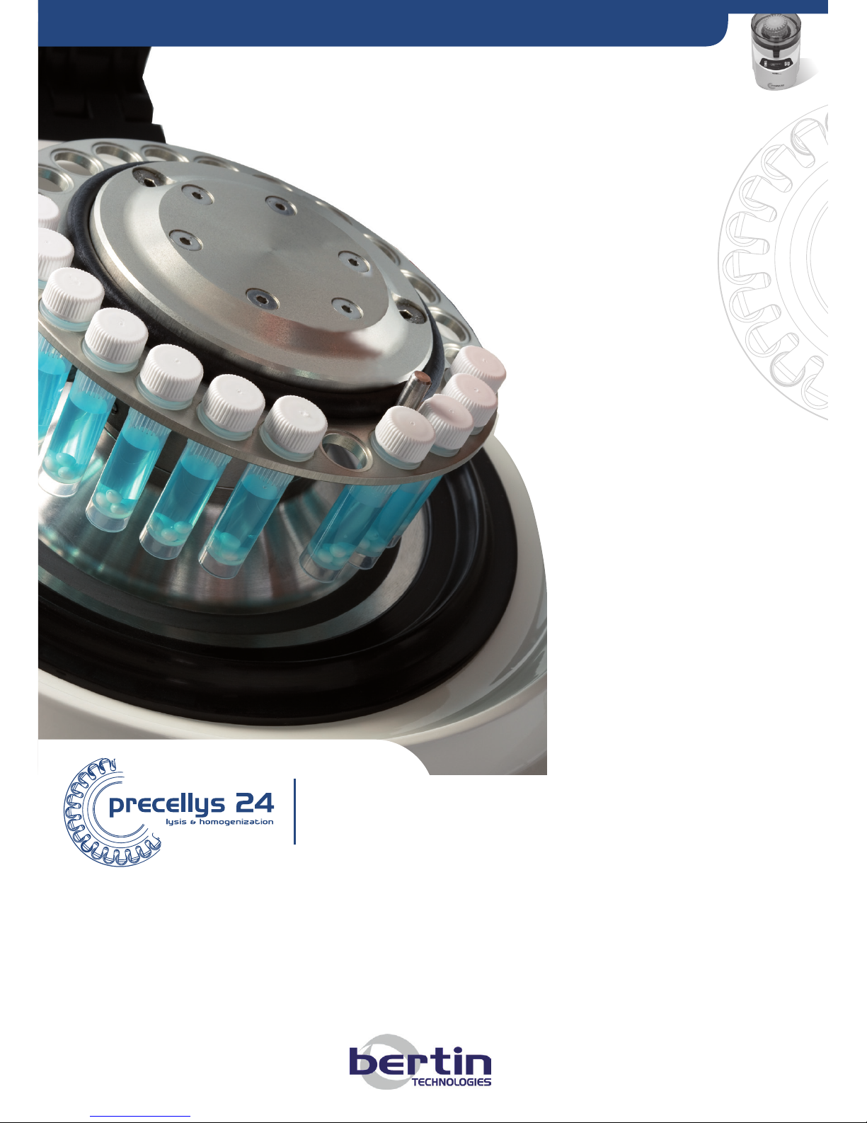
NEW GENERATION Tissue homogenizer
SAMPLE PREPARATION & CELL LYSIS
USER MANUAL / MANUEL UTILISATEUR
PRECELLYS
®
24 & PRECELLYS®24-DUAL
Page 2

Precellys®24 & Precellys®24-Dual
Page 2
USER MANUAL
Manufactured by:
BERTIN TECHNOLOGIES
Parc d’activités du Pas du Lac
10 bis, avenue Ampère - BP 284
78053 Saint Quentin en Yvelines Cedex
France
Tel: + 33 (0)1 39 30 60 00
Mail: [email protected]
User manual code: 03720-800-DU004-I
Page 3
Page 3
TABLE OF CONTENTS
1. INTRODUCTION
1.1 Safety Information
1.2 Warranty
1.3 Precellys®24/ Precellys®24-Dual’s Reference
1.4 Manufacturer Information
1.5 Technical Support
2. DESCRIPTION OF THE PRECELLYS®24/ PRECELLYS®24-DUAL
2.1 Product Overview
2.2 Tube Motion
2.3 Lysing kits
2.4 Programming
2.5 Presentation of the Keypad
2.6 Technical Features
3. TRANSPORT / STORAGE
3.1 Transport
3.2 Storage
4. INSTALLATION
4.1 Unpacking
4.2 Installation and Connecting the Power Supply
5. INSTRUCTIONS FOR USE
5.1 Preparing Samples
5.2 Starting a Run
6. ADJUSTING PARAMETERS
6.1 Accessing the Parameter Adjustment Menu
6.2 Parameters Adjustment Menu
6.3 Operating Ranges for Parameter Adjustments
7. ALARMS
7.1 Alarm Messages before Starting a Run
7.2 Run Interruption by Alarm Messages
7.3 What to Do When an Alarm Message Occurs
8. MAINTENANCE
8.1 Cleaning and Decontamination
8.2 Troubleshooting Guide
8.3 Replacing Spare Parts
8.4 Service Menu
9. REPARATION / ELIMINATION
9.1 Reparation
9.2 Elimination
Page 4
Precellys®24 & Precellys®24-Dual
Page 4
USER MANUAL
This user manual includes the
required information regarding
unpacking, operation and
maintenance of the Precellys
®
24/
Precellys®24-Dual lyser /
homogeniser.
The product’s technical
specifications and the
following information are
subject to change without
prior notice.
1 Introduction
1.1 Safety Information
This user manual must be read carefully before operating the Precellys®24/
Precellys®24-Dual lyser/homogeniser.
If there is any doubt or concern about the safety of the equipment,
please contact your local distributor.
Bertin Technologies is not responsible for any damage or injury that may occur as a result of operating the instrument in a different way to that stated in
this document.
Symbol signification
Danger
Necessity to respect the safety instructions
Biological Danger
The no respect of the symbol can cause risks of personal and
environmental injury.
This symbol is delivered separately and must be pasted in front
of the unit for an utilisation with infectious samples.
Separate collection of electrical and electronic equipments to
the directive 2002/96/EC.
Necessity to respect the measures in effect.
1.1.1 Use of the lysing kits
Depending on the parameters of the Precellys®24/ Precellys®24-Dual (speed,
number of cycles, cycle duration, waiting time between two cycles), an important overheating of the lysing tubes may lead to their sudden degradation.
To prevent any risk to the user when running thePrecellys
®
24/ Precellys®24Dual it is scrupulously recommended to use the lysing kits produced by Bertin
Technologies and respect the use limits defined for each lysing kit. Those
limits specify maximum level for parameters (speed, number of cycles, cycle
duration, waiting time between two cycles, etc). It will ensure good biological
samples preparation.
The use limits of every Lysing kits are available on the website www.precellys.
com or in each Bertin Technologies Kits.
1.1.2 Risk of Electric Shock
Although this equipment is fully insulated and grounded, it is important for all
users to be aware of the potential hazard of using liquids close to a power
supply. If any liquids are spilled, disconnect immediately the instrument from
the main power supply (remove the power cord from the AC power input on
the rear panel) and clean the equipment and the surrounding area.
Do not reconnect the equipment until it has been fully inspected.
INTRODUCTION
Page 5
Page 5
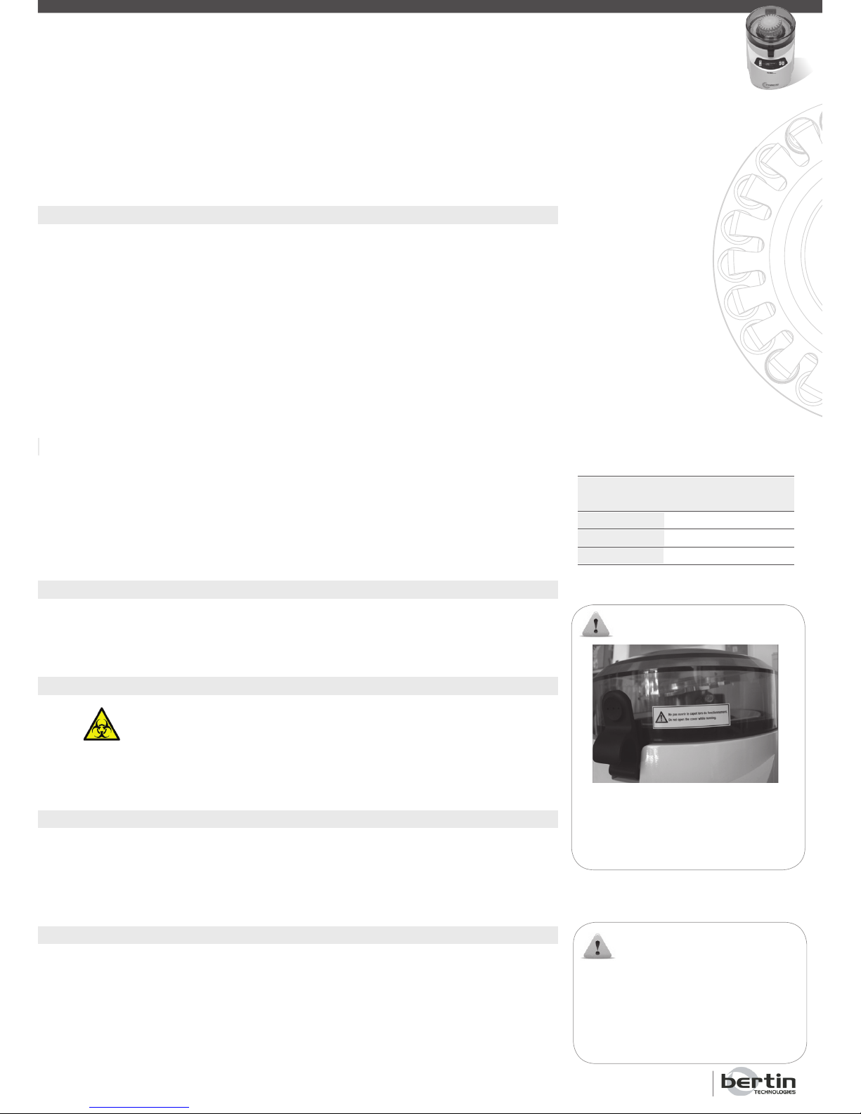
Ne pas ouvrir le capot lors
du fonctionnement.
Do not open the cover while
running.
WARNING :
INTRODUCTION
1.1.3 Incorrect Operation
Operating this equipment in other ways than those detailed in this user manual
may impair the protection of the unit.
• Do not turn the unit upside down: the Precellys®24/Precellys®24-Dual must
always rest on its 4 feet for fear of damaging internal components or breaking plastic casing.
• Do not operate the unit when the casing is removed; potentially lethal vol-
tage exists within the instrument.
• Do not operate the unit with the safety ground disconnected.
• Do not install unauthorised cards, spare components or accessories as this
may impair the safety of the unit and the warranty will be void.
• Do not overfill the tubes as this may lead to liquid contamination and impair
the safety of the unit.
• Check that the voltage indicated on the rear panel of the unit matches to
the local power supply.
• Check that the power cord is properly plugged-in. Colour codes are as
follows:
1.1.4 Fuses
The equipment contains one replaceable external fuse located on the rear panel. If the fuse is to be replaced, please use the following fuse 5x20 – T 10 A
– H 250 V. It can easily be replaced by the user with a screwdriver (see §8.2).
1.1.5 Biological Risks
Wear gloves when handling samples and follow strictly all of the safety
instructions related to bio-hazardous agents to prevent any risk of
contamination. The waste produced by the normal operation of the
instrument must be disposed of in biological waste containers and handled by
specialised companies.
1.1.5 Biological Risks
Wear gloves when handling samples and follow strictly all of the safety instructions related to bio-hazardous agents to prevent any risk of contamination. The
waste produced by the normal operation of the instrument must be disposed of
in biological waste containers and handled by specialised companies.
1.1.6 Warning Symbols
The symbols on the right can be found in various places on the Precellys
®
24/
Precellys®24-Dual.
Please follow instructions associated with these symbols.
The equipment can only be repaired by either the authorised distributor or
the manufacturer.
Lire attentivement la notice avant
utilisation.
Read carefully user manual before
operating.
WARNING :
USA
Code
Black
White
Green
International
Code
Brown
Blue
Yellow & Green
Phase Live
Neutral
Earth/Ground
Page 6

Precellys®24 & Precellys®24-Dual
Page 6
USER MANUAL
1.1.7 Noise Level
The equipment’s noise level is below 70 dBa when in operating mode at a
speed of 6500 rpm.
1.1.8 Electromagnetic Interference
WARNING: This is a Class A apparatus. The equipment may cause
radio-electric interference in a residential environment. In this case,
it is recommended that the user takes appropriate measures.
1.1.9 Intensive Use
If this device is used in an intensive manner (high speed, long cycle duration,
fully loaded with 24 tubes, high number of cycles), the temperature of the
system will increase. The increased temperature level may cause the thermal
security protection to function. In this case, the electrical power input of the
motor will be cut automatically to avoid the overheating of this device.
1.2 Warranty
Bertin Technologies certifies that this product is free of defects at the time
of shipment.
This warranty is limited to a period of one (1) year and it does not apply to the
following parts: fuses, toric joint, containment seal and indented plate.
This warranty is not applicable in the following circumstances:
• The equipment has not been installed, operated or maintained according to
the instructions described in this user manual.
• The equipment has been repaired or modified by unauthorised personnel.
• The equipment serial number has been damaged or removed.
1.3 Precellys
®
24’s and Precellys®24-Dual’s References
Code: • Precellys
®
24: PRECELLYS 03119.200.RD000
• Precellys®24-Dual: PRECELLYS 03119.200.RD010
1.4 Manufacturer Information
BERTIN TECHNOLOGIES
Parc d’activités du Pas du Lac
10 bis, avenue Ampère - BP 284
78053 Saint Quentin en Yvelines Cedex - France
Tel: +33 (0)1 39 30 60 70
Fax: +33 (0)1 39 30 61 85
1.5 Technical Support
First, read this user manual very carefully. If you cannot solve the problem
after having used this manual, please contact the nearest distributor’s office
or Bertin Technologies’ Customer Support Department located in France (see
the address above).
INTRODUCTION / DESCRIPTION
Page 7
Page 7
2. Description of the Precellys®24/Precellys®24-Dual
2.1 Product Overview
The Precellys®24/ Precellys®24-Dual lyser / homogeniser has been designed
to lyse and to homogenise biological samples contained in grinding tubes, at
variable speeds. It can simultaneously agitate tubes with biological sample
volumes up to 7 mL at very high speed.
Precellys®24/Precellys®24-Dual’s main advantages include:
• Easy tube loading: an innovative system automatically blocks the grinding
tubes during operation.
• Easy decontamination: zones which have to be decontaminated are easily
accessible.
• Flexible and easy cycle programming (time, speed…).
• No alteration of the biological samples and no cross-contamination.
• Efficient and homogeneous lysis in all tubes.
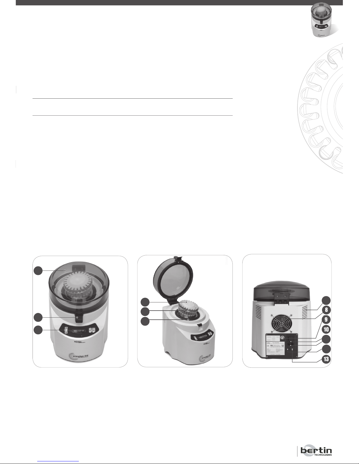
The Precellys®24/ Precellys®24-Dual lyser / homogeniser is shown hereafter:
1 - cover
2 - locking latch
3 - keypad
2
3
4 - tubes holder
5 - indented plate:
Precellys®24 : 24x2mL
Precellys®24-Dual : 12x2mL
6x7mL
6 - containment seal
4
5
6
7 - air opening
8 - fan
9 - On/Off button
10 - main power supply plug
11 - fuse
12 - 120V/240V switch
13 - maintenance plug
DESCRIPTION
7
8
9
10
13
1
11
12
Page 8
Precellys®24 & Precellys®24-Dual
Page 8
USER MANUAL
WARNING:
2.2 Tube Motion
Thanks to the equipment’s design and symmetry, every tube of the same
size strictly follows the same motion to ensure the same level of lysis and
homogenisation for each sample.
The centre of gravity of the tubes follows a tri-dimensional path on a sphere’s
surface. While the mixture contained in grinding tubes moves in all directions,
it moves primarily in the vertical axis to allow for efficient homogenisation.
The movement generated by the Precellys
®
24/ Precellys®24-Dual equipment
is called a “precession” movement (i.e. grinding tubes are not rotated).
Each 2 mL tube has a stroke of 8 mm projected on the main vertical axis.
Each 7 mL tube has a stroke of 8.5 mm projected on the main vertical axis.
The tubes must be compatible with the holder and must withstand 600 G of
linear acceleration during 5 minutes without suffering any deformation (see
preconisation of use § 1.1.1 and recommended references § 2.3).
Precession movement doing biological sample homogenisation also causes
an increase of temperature of the samples and the equipment.
2.3 Lysing kits Precellys
®
24/Precellys®24-Dual
The Precellys lysing kits range includes tubes ready-to-use containing beads
adapted to every sample type. References of the lysing kits are available on
the website www.precellys.com.
DESCRIPTION
2.4 Programming
The Precellys®24 lyser / homogeniser has been designed to operate at a
maximum speed of 6,800 rpm. The Precellys®24-Dual lyser/homogeniser
has been limited at a maximum speed of 6,500 rpm. A run consists of one or
several cycles, between which the cover must not be opened.
Speed as well as other settings can be adjusted both in one of the five programs available on the keypad:
Parameter
Speed
Number of cycles
Cycle duration
Waiting time between 2 cycles
Operating range
From 5,000 to 6,800 (6,500) rpm in increments of 100 rpm
From 1 to 3
From 5 to 90 seconds in increments of 1 second
From 5 to 120 seconds in increments of 1 second
The increase of temperature is
higher for 7 mL tubes than for
2 mL tubes.
VISIT:
www.precellys.com
to know the evolutions of the
consumables dedicated to
Precellys sample preparation
range.
Page 9
Page 9
DESCRIPTION
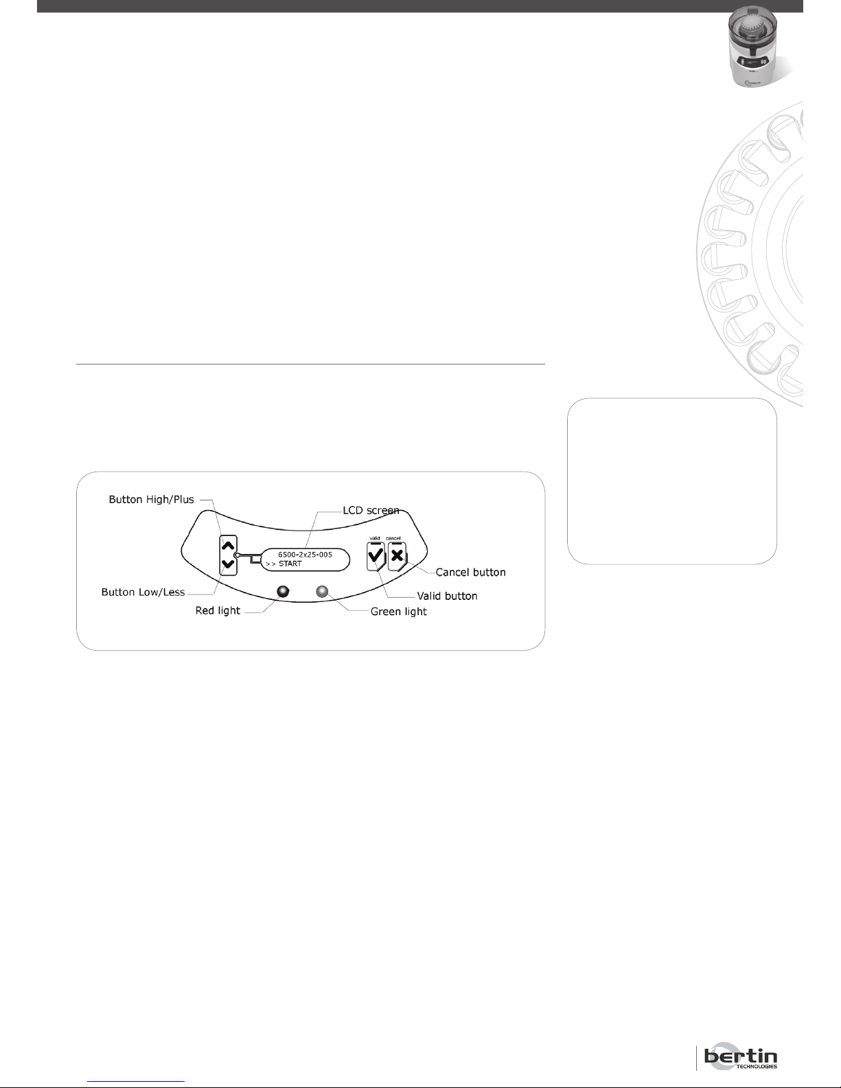
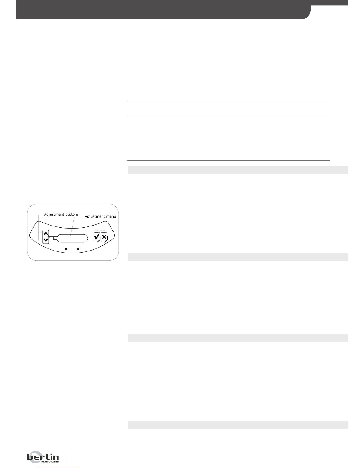
The user can adjust four different homogenisation settings (see § 6) with
this interface. Buttons called “High / Plus” and “Low / Less” are used to
navigate through the menu and to adjust parameters. When used for navigation, the “High / Plus” and “Low / Less” buttons can be used to move the
selection cursor. The same buttons also allow the adjustment of the homogenisation parameters.
NOTE:
The green light can have 3
different states: on, flashing
or off.
The red light can have 3 different states: on, flashing or off.
The operator is responsible for programming the unit. For each speed range,
the manufacturer recommends an operating range to prevent abnormal temperature rise. See § 6.3 for further details.
For high speed operation, it is recommended to reduce each cycle duration
and let the unit cool down between 2 cycles (at least 2 minutes). A security
device disables the unit to prevent overheating.
2.5 Presentation of the Keypad
The LCD screen lights up when the Precellys
®
24/ Precellys®24-Dual equipment is switched on. These messages guide you for programming and controlling the cycles. The keypad (see diagram below) consists of a LCD screen,
4 buttons and 2 lights (green, red).
Page 10
Precellys®24 & Precellys®24-Dual
Page 10
USER MANUAL
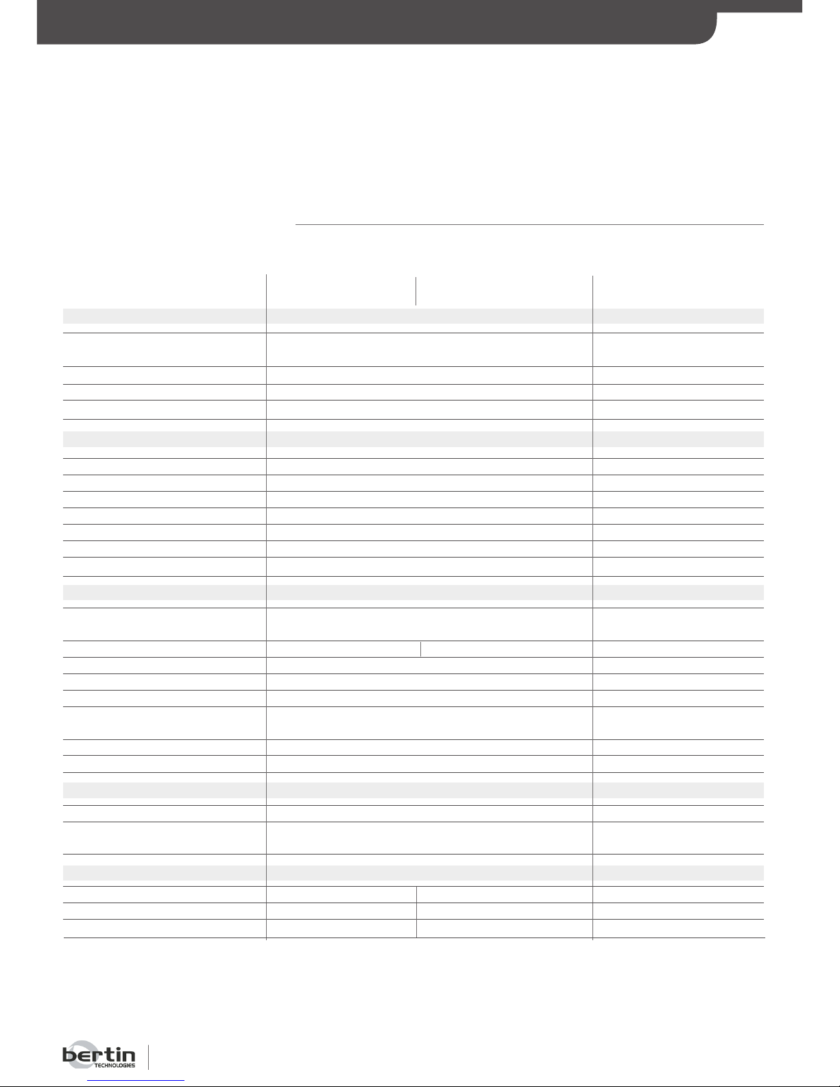
230 V – 50 Hz (Europe standard)
110 V – 60 Hz (US standard)
<1 kVA
5x20 – T 10 A – H 250 V
Class A apparatus
290 mm
375 mm
370 mm
29,8 kg
15-30°C
15-85 % HR
< 2000 m
5
5000 – 6800 rpm 5000 – 6500 rpm
1 – 3
5 – 90 s
5 – 120 s
2 – 5 min
< 4 s
< 4 s
4 buttons
A 2 line LCD screen, 16 characters, back-light
2 lights (1 green, 1 red)
24
2 mL
1.4 mL
2.6 Technical Features
DESCRIPTION
Technical characteristics
Power requirements
Power consumption
Fuse specifications
Safety
Length
Width
Height
Weight
Operating temperature
Humidity
Altitude
Number of pre-registered
programs
Speed
Number of cycles
Cycle duration
Waiting time between 2 cycles
Rest time between 2
consecutive runs
Acceleration time
Deceleration time
Keypad
Display
Number of tubes
Total volume
Sample volume
12 / 6
2 mL / 7 mL
1.4 mL / 5 mL
Physical / Environmental conditions
Operating characteristics
User interface
Capacity
600 mm cover open
Modifiable programs
See adjustment limit § 6.3
See adjustment limit § 6.3
See adjustment limit § 6.3
Precellys®24 Precellys®24-Dual Remark
Page 11
Page 11
TRANSPORT / STORAGE
3. Transport / Storage
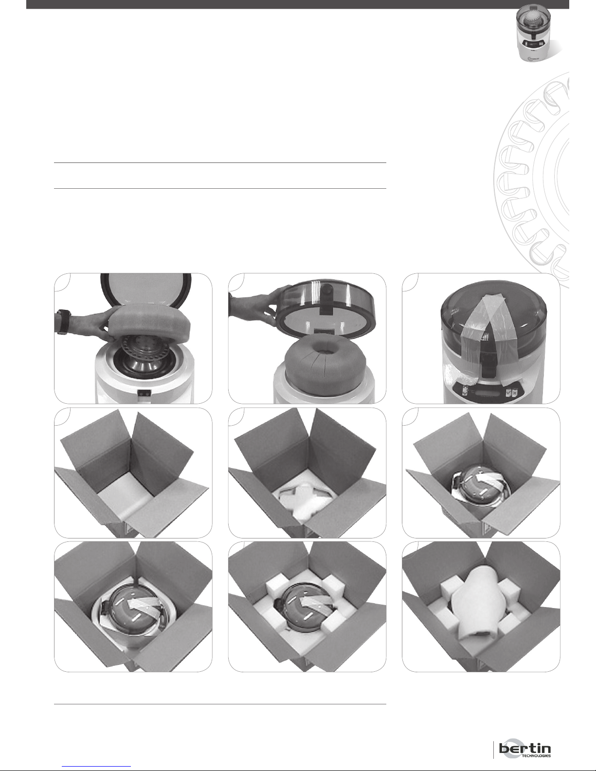
3.1 Transport
Avoid violent shocks that may damage the equipment.
Before transporting the equipment, it is necessary to:
• 1 > Place the protection foam under the cover
• 2 > Close the cover.
• 3 > Block the cover with adhesive tape.
3.2 Storage
The unit must be stored in a dry area at a temperature ranging from +0°C
to +50°C.
1 2 3
6
5
4
7
8
9
Page 12
Precellys®24 & Precellys®24-Dual
Page 12
USER MANUAL
INSTALLATION
4. Installation
4.1 Unpacking
1.
Check the content of the box. The box must contain the following items:
Precellys®24 Precellys®24-Dual
1 Precellys®24 1 Precellys®24-Dual
1 indented plate and 1 toric joint 2 indented plate and 1 toric joint
1 user manual
1 CE Declaration of Conformity
1 AC power cord (European plug*)
1 extra toric joint
1 QC report
* A plug adapter or a compatible power cord (not included) is required for
countries as the UK, the USA, Canada, Japan, etc.
Should one of these items be missing, please contact immediately your local
distributor’s office.
2.
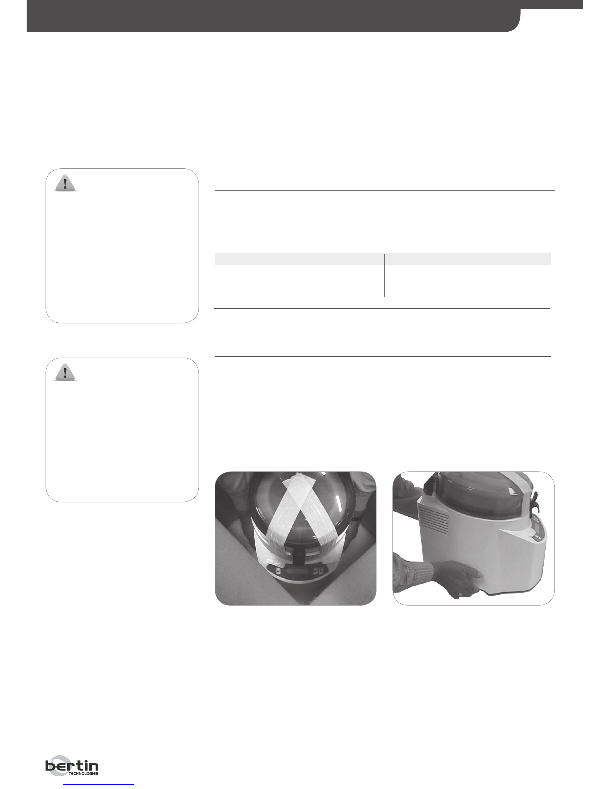
Remove the Precellys®24/ Precellys®24-Dual from the box and place it on a
clean, horizontal and stable surface (weight = 29.8 kg).
3.
Unpack the Precellys®24/ Precellys®24-Dual with care and inspect it carefully.
Report any damage to the carrier immediately.
4.
Save the packaging material, in case a return is necessary.
WARNING:
Do not connect the unit to
the main supply before the
installation is over.
Do not turn the unit upside
down: the Precellys®24/
Precellys®24- Dual must
always rest on its 4 feet for fear
of damaging internal components
or breaking plastic casing.
WARNING:
To remove the unit from the
box, do not lift it by holding the
cover. It must be removed by
holding the notches located on
both sides of the unit. For more
convenience, notches are also
present in the protective foam.
Page 13
Page 13
4.2 Installation and Connecting the Power Supply
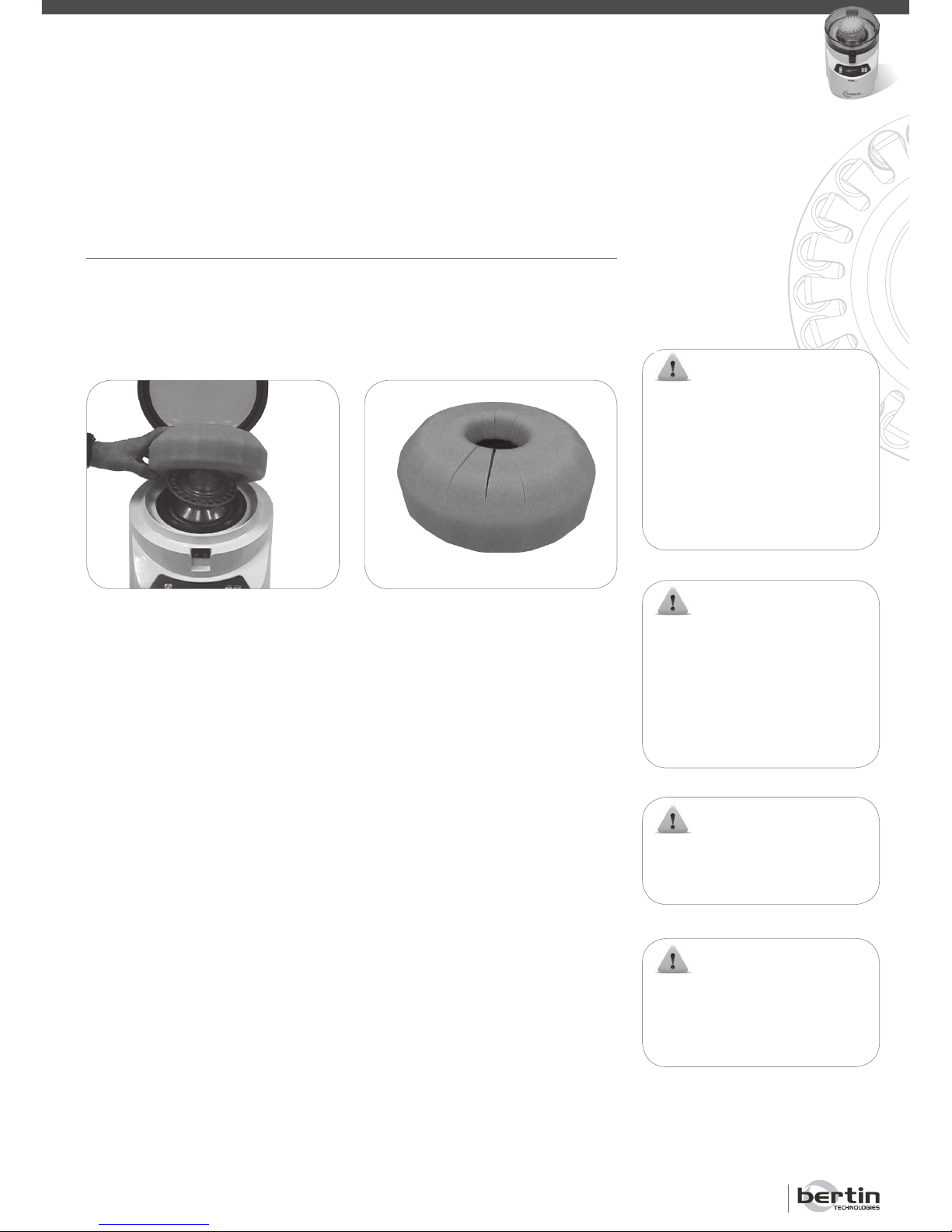
1.
Remove the protective foam located around the holder under the cover.
2.
Put the toric joint in place (see § 8.2.2).
3.
Check that the voltage switch located at the back of the unit matches the
voltage delivered by your electric power supply (see § 2.1).
4.
Ensure that both air openings and the cooling fan are clear.
5.
Plug the Precellys
®
24/ Precellys®24-Dual into the power supply using a com-
patible power cord.
WARNING:
Save this protective foam, as
it must ABSOLUTELY be put
back in place before shipping
the unit. If the unit is returned to
the distributor or manufacturer
without this protection in place,
the warranty will be cancelled.
WARNING:
If the voltage supplied to
the equipment is higher than
that indicated on the voltage
switch (see the rear side of the
equipment), the electronics can
be irreversibly damaged.
WARNING:
Allow at least 15 cm of space
around air inlets and outlets for
proper motor ventilation.
WARNING:
This equipment must be powered
from a main supply which has a
protective ground terminal.
INSTALLATION
Page 14
Precellys®24 & Precellys®24-Dual
Page 14
USER MANUAL
INSTRUCTIONS FOR USE
For each program, the homogenisation settings can be modified and
the unit stores parameters defined
during the last executed cycle (see
§ 6); the default parameters are:
Program 1: 5000-1x15-005
Program 2: 5000-2x20-005
Program 3: 5500-1x20-005
Program 4: 6000-1x30-005
Program 5: 6500-2x20-005
5. Instructions for use
The gloves wearing going with necessary precautions adapted to the infection risks are required during the utilisation of the unit and the handling of the
samples.
5.1 Preparing Samples
The samples have to be prepared in the tubes recommended by Bertin Technologies (see § 2.3).
5.2 Starting a Run
5.2.1 Turning on the Equipment
Turn the Precellys®24/ Precellys®24-Dual on by pressing the ON/OFF button
located on the rear panel near the AC power input.
5.2.2 Starting information
When the unit is turned on, a welcome screen is displayed for a few seconds
showing the following information:
• Precellys 24: Name of the equipment
• R: Number of runs done by the equipment since last reset (see § 8.3)
• T: Operating time (in minutes) corresponding to these runs
5.2.3 Main Menu
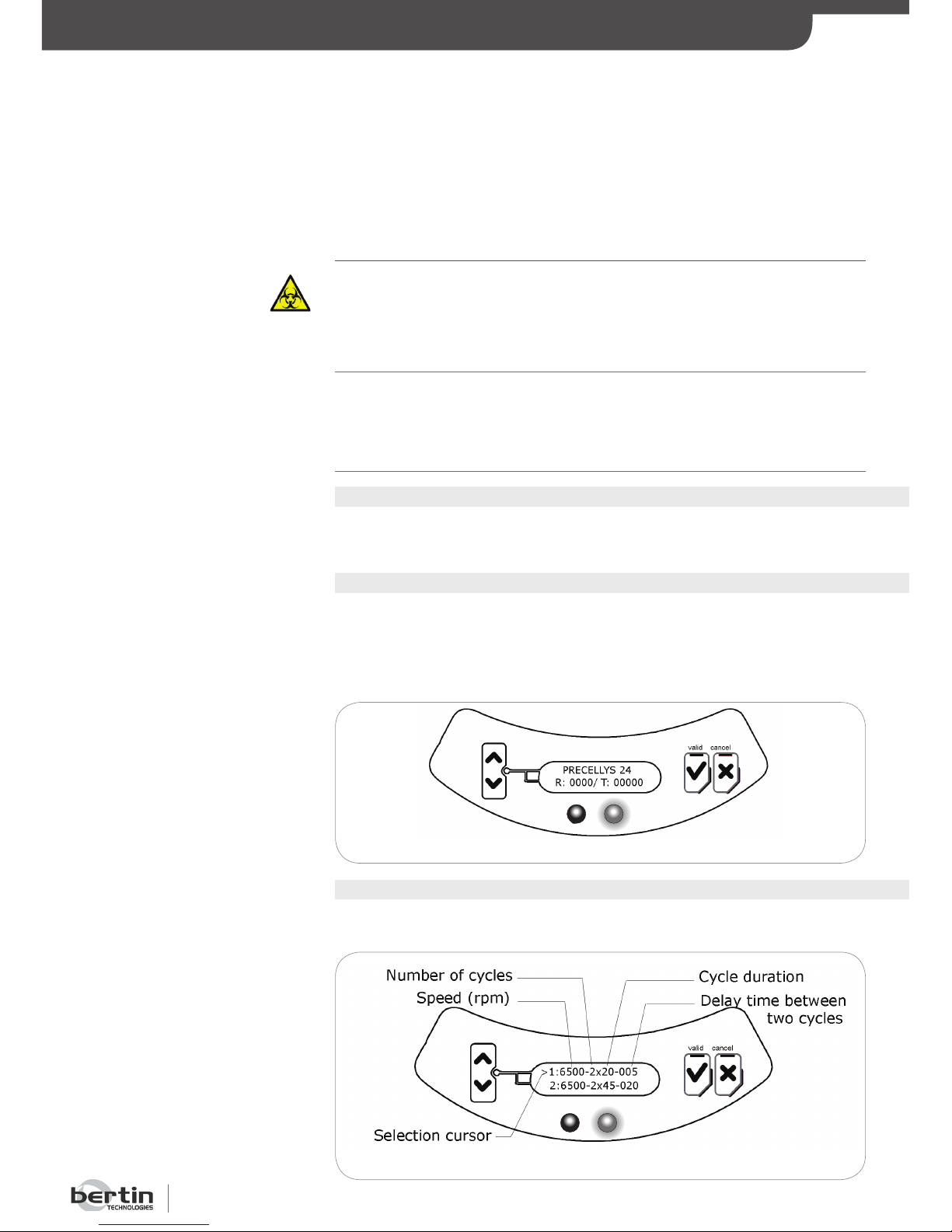
After starting the unit, a menu displays two consecutive programs on the five
available.
Red light is off / green light is on
Red light is off / green light is on
Page 15
Page 15
WARNING:
Never open the cover while the
unit is running.
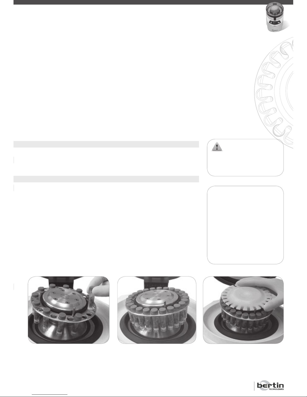
2.Place grinding tubes symmetrically
onto the holder.
NOTE:
When loading tubes, make sure
that:
• The toric joint is properly
installed on the holder’s groove.
• The indented plate must
be centred on the holder and
placed on the toric joint. A
positioning guide helps the
operator to place the indented
plate properly.
INSTRUCTIONS FOR USE
The selection cursor allows to choose the program to be started. The cursor can be moved by using the “Up” and “Down” buttons. By pressing the
“Valid” button, the selected program is displayed on the screen.
The “Start” command is selected by default. By pressing the “Valid” button,
the run starts.
The cursor can be moved by pressing the “Up” and “Down” buttons. Selecting the upper line allows to modify the homogenisation settings (see § 6). By
pressing the “Cancel” button, the main menu listing with five homogenisation
programs is displayed.
5.2.4 Opening the Cover
To open the cover, push the locking handle and raise the cover until you reach
a stop.
5.2.5 Loading lysing Tubes
Lysing tubes (filled with samples) are placed on the holder, and are held down
with the indented plate. The latter has to be removed for loading and unloading tubes.
The Precellys®24 has a capacity for 24x2 mL. The Precellys®24-Dual has a
capacity for 12x2 mL tubes or for 6x7 mL tubes. During a run, only same
type of tubes can be loaded on the tubes holder.
A vacuum system holds the indented plate onto the holder. The indented
plate’s prongs maintain tubes in place while the unit is running, and tubes are
freed when the vacuum stops (a few seconds after the end of the run).
1 2
3
1.Remove the indented plate.
3.Put the indented plate
back in place.
Page 16
Precellys®24 & Precellys®24-Dual
Page 16
USER MANUAL
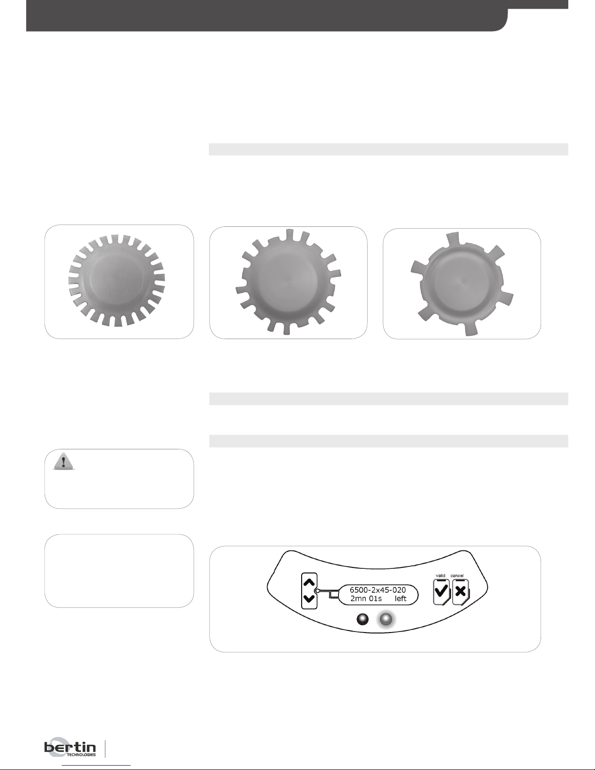
5.2.6 Choice of the indented plate
Each indented plate is specific to a size of tube. Choose the corresponding
indented plate and place it on the holder.
Precellys
®
24-Dual Precellys®24-Dual
Indented plate 12x2 mL Indented plate 6x7 mL
Ref 03119.810.NC009 Ref 03119.810.NC010
5.2.7 Closing the Cover
Close the cover until the locking handle is locked.
5.2.8 Running a Program
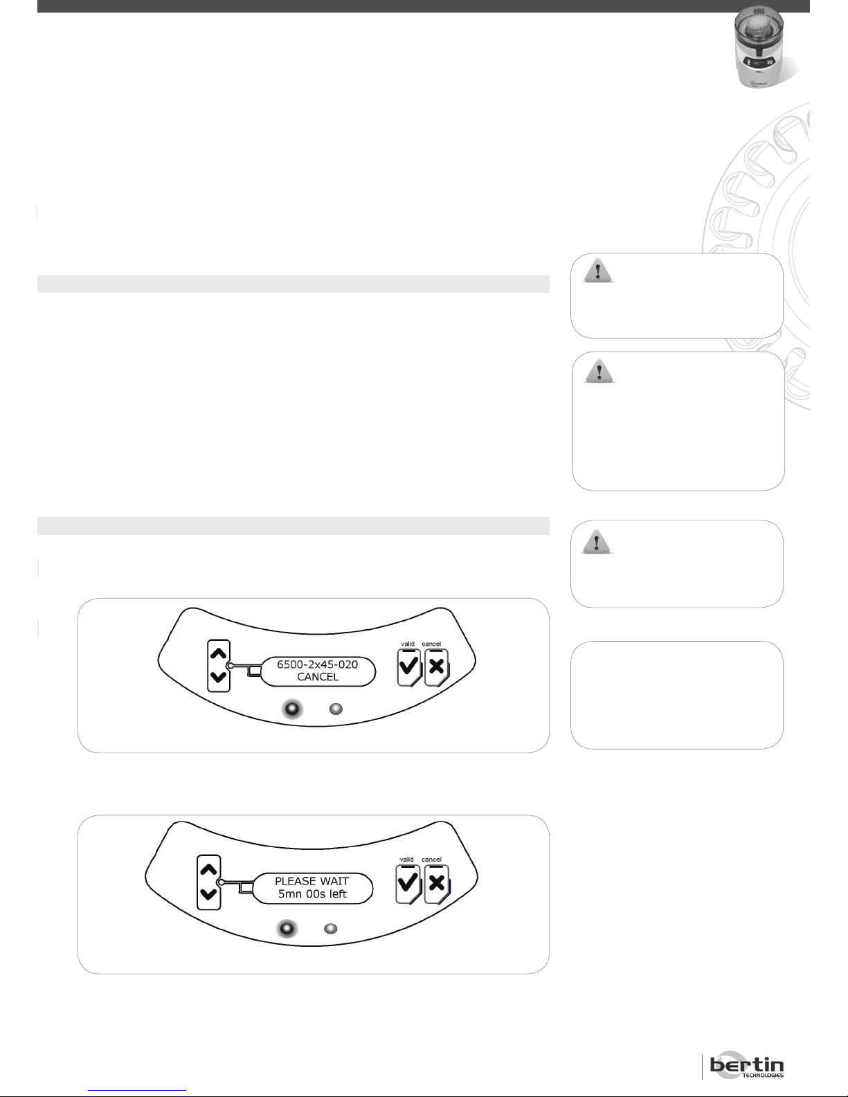
When starting a program by pressing the “Valid” button, the unit puts the
indented plate in depression; during this phase, the message «PLEASE WAIT
LOCKING» is displayed.
When tubes are properly held (i.e. depression is sufficient), the run starts, the
green light flashes and the following indications are displayed on the screen:
Red light is off / green light is on
INSTRUCTIONS FOR USE
REMARK:
Time and speed are not
modifiable during the run to
prevent any wrong moves.
Precellys®24
Indented plate 24x2 mL
Ref 03119.810.NC002
WARNING:
Wait until the complete stop of
the unit before opening the cover.
Page 17
Page 17
WARNING:
Wait until the complete stop of
the unit before opening the cover.
Red light is on / green light is off
After the complete stop of the unit, the LCR screen displays the following
sub-menu:
Red light is on / green light is off
WARNING:
Wait until the complete stop of
the unit before opening the cover.
The depression under the indented plate stops about 5 seconds after the
unit stops. The indented plate cannot be removed from the holder during
this time.
INSTRUCTIONS FOR USE
WARNING:
To prevent overheating, a rest
period of 2 to 5 minutes between
runs is strongly recommended,
as indicated on the LCD screen.
REMARK:
If «CANCEL» is pressed in the 10
first seconds of the cycle, waiting
time between two cycles is not
activated.
A timer (in minutes and seconds) counts down the remaining time before the
end of the run. This time takes into account both acceleration (< 4 s) and
deceleration (< 4 s) stages.
5.2.9 Ending a Run
At the end of a run, the holder is stopped and the unit displays the main
menu. The depression under the indented plate stops about 5 seconds after
the unit stops. The indented plate cannot be removed from the holder during
this time.
Homogenisation settings cannot be changed once the run is in progress, to
prevent any operator’s mistake.
At the end of each run and for safety purposes, the unit will automatically
be unavailable for a short period of time, depending upon the programmed
speed level and cycle duration. The message “PLEASE WAIT” is displayed
and the red LED is on.
5.2.10 Interruption du cycle par l’utilisateur
The user can stop a run by pressing the «Cancel» button at any time. The unit
displays the «Cancel» information until the run has completely stopped.
Page 18
Precellys®24 & Precellys®24-Dual
Page 18
USER MANUAL
ADJUSTING PARAMETERS
6. Adjusting Parameters
6.1 Accessing the Parameter Adjustment Menu
From the sub-menu, the user can adjust the settings of all the five programs,
by moving the cursor to the line 1 with the “Up” button, then pressing the
“Valid” button.
6.2 Parameters Adjustment Menu
6.2.1 Adjusting the Speed
When the adjustment menu is selected, the message “SPEED (rpm)” is displayed and the speed value flashes.
The user can change the speed value using the “Up” and “Down” buttons.
The speed adjustment ranges from 5,000 rpm to 6,800 (6,500) rpm in increments of 100 rpm.
When the desired value is reached, the user can select it by pressing the “Val-
id” button or return to the previous menu by pressing the “Cancel” button.
6.2.2 Adjusting the Number of Cycles
Once the speed is adjusted, the message “RUN NUMBER” displays on the
screen and the number of cycles flashes.
The user can change the number of cycles using the “Up” and “Down” buttons. The number of cycles ranges from 1 to 3.
When the desired value is reached, the user can select it by pressing the “Val-
id” button or return to the previous menu by pressing the “Cancel” button.
6.2.3 Adjusting the Duration of the cycle
Once the number of cycles is adjusted, the message “ RUN TIME” displays
on the screen and the duration of the cycle flashes.
The user can change the cycle’s duration using the “Up” and “Down” buttons.
The cycle’s duration ranges from 5 seconds to 90 seconds in increments of
1 second.
When the desired value is reached, the user can select it by pressing the “Val-
id” button or return to the previous menu by pressing the “Cancel” button.
6.2.4 Adjusting the Waiting Time between 2 Cycles
Once the cycle’s duration is adjusted, the message “ PAUSE(s)” displays on
the screen and the waiting time between 2 cycles flashes.
Page 19
Page 19
ADJUSTING PARAMETERS / ALARMS
NOTE:
A temperature sensor is used
to automatically disconnect the
engine power supply (instant
stop of the system) in case of
important overheating. This
alarm can be triggered during a
run. When the warning message
appears on the display (see §
7.2.4), it is necessary to apply
the procedure described in § 7.3.
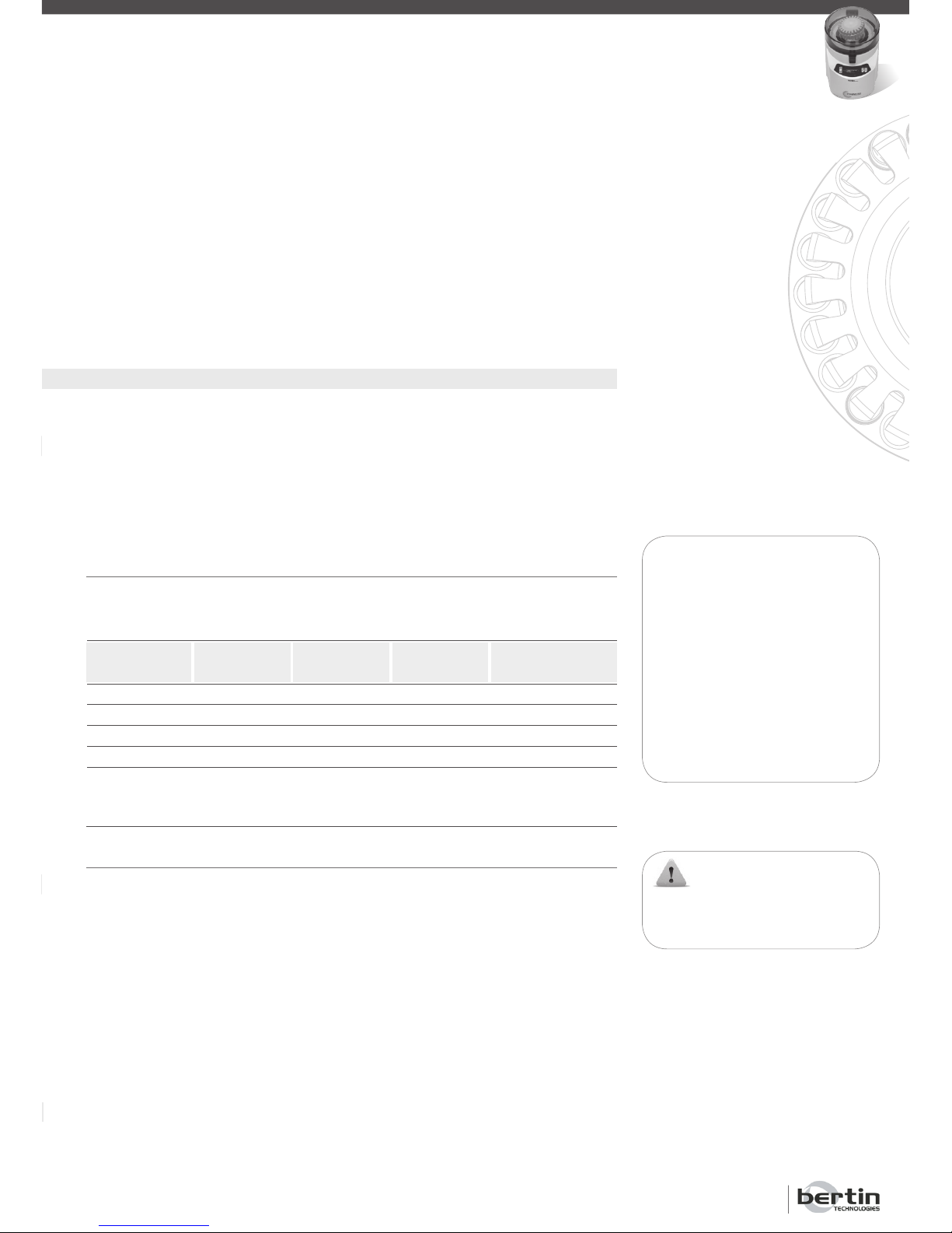
Speed (rpm)
5000 to 6200
6300 to 6500
6600 to 6800*
Run
Number
1 to 3
1 to 3
1 to 3
Run
Time (s)
5 to 90
5 to 30
31 to 60
5 to 30
Pause (s)
5 to 120
5 to 120
15 to 120
30 to 120
Waiting time between 2 cycles
2 to 5 mn
5 mn
5 mn
* Available only for Precellys®24.
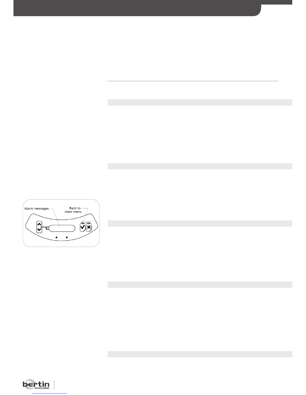
7. Alarms
7.1 Alarm Mesasges before Starting a Run
When the user presses the “Valid” button to start a run, the system checks
information from the different sensors before allowing a run to start:
• Pressure sensor,
• Cover sensor.
When the pressure is insufficient, the message “PRESSURE ALARM CHECK
SYSTEM” is displayed on the screen.
If the cover is not closed properly, the message “TOP ALARM CHECK SYS-
TEM” is displayed on the screen:
The alarm display lasts 5 seconds, then the unit returns to the sub-menu:
Actions to be done in case of alarm are described in § 7.3.
In case of a pressure alarm, the vacuum pump keeps running for 10 seconds,
in order to allow the user to reposition the indented plate properly.
WARNING:
Do not open the cover when the
sample holder is moving.
The user can change the waiting time between 2 cycles using the “Up” and
“Down” buttons. The waiting time between 2 cycles ranges from 5 seconds
to 120 seconds in increments of 1 second.
When the desired value is reached, the user can select it by pressing the “Val-
id” button or return to the previous menu by pressing the “Cancel” button.
6.2.5 Ending the Parameter Adjustments
Once the waiting time between 2 cycles is adjusted, the sub-menu is displayed on the screen showing the new program 2 parameters. This program
can be started by selecting the “START (2)” line and then by pressing the
“Valid” button.
When returning to the sub-menu, the unit automatically saves the new parameters.
6.3 Operating Ranges for Parameter Adjustments
In order to assure the optimal operation of this device, it is possible to use the
parameters indicated in the table below:
Page 20
Precellys®24 & Precellys®24-Dual
Page 20
USER MANUAL
ALARMS
7.2 Run Interruption by Alarm Messages
A run in progress can be stopped by alarm messages.
7.2.1 Pressure alarm
If the pressure under the indented plate increases when a run is in progress
and the unit can no longer hold the indented plate down, the pressure alarm
is set off. The run stops immediately and the message “PRESSURE ALARM
PUSH VALID” is displayed on the screen.
To return to the main menu, the user must press the “Valid” button.
Actions to be done in case of alarm are described in § 7.3.
7.2.2 Cover Alarm
If the cover is opened while a run is in progress, the cover alarm sets off and
the run stops immediately. The message “TOP ALARM PUSH VALID” is
displayed on the screen.
To return to the main menu, the user must press the “Valid” button.
Actions to be done in case of alarm are described in § 7.3.
7.2.3 Speed Error Alarm
If the actual speed is different from the assigned speed, the speed error
alarm sets off and the run stops immediately. The message “ERR SPEED
SENSOR PUSH VALID” is displayed on the screen.
To return to the main menu, the user must press the “Valid” button.
Actions to be done in case of alarm are described in § 7.3.
7.2.4 Engine Temperature Alarm
If the engine temperature reaches the safety limit before overheating the instrument, the engine temperature alarm sets off and the run stops immediately. The message “OVER TEMP WAIT! PUSH VALID” is displayed on the
screen.
To return to the main menu, the user must press the “Valid” button.
Actions to be done in case of alarm are described in § 7.3.
7.2.5 Power Supply Alarm
If a synchronization error with the power supply occurs, the power supply
alarm sets off and the run stops immediately. The message “ERR POWER
SUPPLY PUSH VALID” is displayed on the screen.
Page 21
Page 21
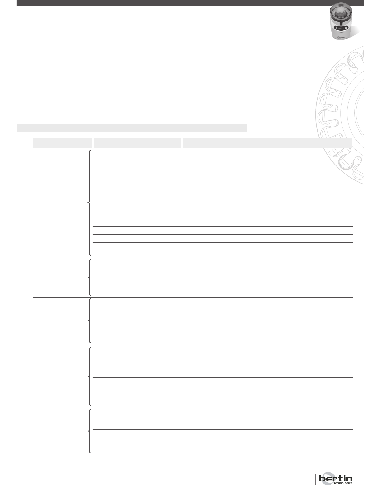
Alarm message
Pressure alarm
Top alarm
Err speed sensor
Over temp wait!
Err power supply
Possible cause
Tubes recommended by Bertin
Technologies (see § 2.3) are
not positioned properly.
The indented plate is not
positioned properly.
The indented plate doesn’t
square to the type of the tubes.
The toric joint is not positioned
properly.
The indented plate is damaged.
The toric joint is damaged.
The vacuum is not working
properly
The cover is not locked
properly
Detection system is faulty.
Speed regulation or detection
system is faulty.
Power supply is not suitable.
Engine temperature has
reached the safety limit.
Detection system is faulty.
Power supply is not suitable.
No synchronization between
unit and power supply.
Action(s)
1.Reposition the grinding tubes on the holder.
2. Press in the middle of indented plate during depression phase
(cover open).
Reposition the indented plate on the holder and make sure the
indented plate is placed properly using the positioning guide.
Change the indented plate and place the adapted indented plate
on the holder.
Reposition the toric joint on the holder and make sure it is adjusted properly to the holder’s groove.
Replace indented plate.
Replace toric joint.
1.Turn off the unit.
2.Contact technical assistance.
1.Check that nothing prevents the cover from closing.
2.Press cover and ensure the handle is locked properly.
1.Turn off the unit
2.Contact technical assistance.
Check the voltage on the back of the unit matches that delivered
by the main power supply.
1.Turn off the unit.
2.Contact technical assistance.
1.Leave the unit on so that the motor ventilation can run.
2.Ensure air openings and the cooling fan are clear.
3.After 30 minutes of cooling, if the alarm is still on, contact
technical assistance.
1.Turn off the unit.
2.Contact technical assistance.
Check the voltage on the back of the unit matches that delivered
by the main power supply.
1.Turn off the unit.
2.Contact technical assistance.
ALARMS
To return to the main menu, the user must press the “Valid” button.
Actions to be done in case of alarm are described in § 7.3.
7.3 What to Do When an Alarm Message Occurs
Page 22
Precellys®24 & Precellys®24-Dual
Page 22
USER MANUAL
8. Maintenance
Before all maintenance operations, the unit must be cleaned and decontaminated according with the infection risk related to the treated samples and with
the protection’s equipment adapted to the rules in effect.
8.1 Cleaning and Decontamination
8.1.1 Recommendations
The casing of the unit can be cleaned up with a sponge or a damp cloth,
moistened with water or alcohol.
8.1.2 Exemple of Decontamination Procedure
If a tube breaks when a run is in progress, decontaminate parts that may have
been contaminated with an appropriate disinfectant.
The decontamination procedure is of the sole responsibility of the user.
Parts that may have been contaminated can be cleaned with a sponge or a
damp cloth moistened with bleach at 6° Cl.
In case another decontamination procedure is to be applied, please first contact technical assistance to ensure the compatibility of the new procedure
with the instrument.
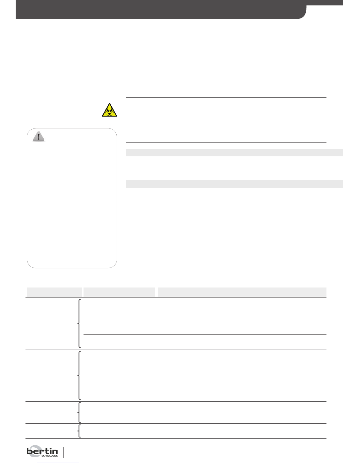
8.2 Troubleshooting Guide
List of main problems during the use and actions to be done are presented
in the following table:
Common problem
The fan does not
work.
No display on the
screen.
One or several
tubes are not tight.
Power cut.
Possible cause
No power on the
main plug.
Faulty fuse.
Faulty cooling system.
No power on the main
power plug.
Faulty fuse.
Faulty display system.
The cap is not properly
screwed or the tube is
faulty.
-
Action(s)
1.Check main voltage.
2.Check the voltage of the unit matches that delivered by the main
power supply.
3.Check the unit is plugged in properly.
Replace fuse.
1.Turn off the unit.
2.Contact technical assistance.
1.Check main power voltage.
2.Check the voltage of the unit matches that delivered by the main
power supply.
3.Check the unit is plugged in properly.
Replace fuse.
1.Turn off the unit.
2.Contact technical assistance.
If a dangerous or potentially-dangerous product is contained
in the tube, apply the proper decontamination procedure.
For safety purpuses, the indented plate is held down by depression.
Turn the unit back on the remove the indented plate.
MAINTENANCE
WARNING:
For safety purposes and to
prevent any damage of the
unit, the recommendations
listed below should be strictly
followed:
Do not spray water or alcohol
directly on the unit, especially in
the air openings
and the fan.
Always disconnect the power
cord before cleaning.
Do not use any type of scrapers.
Do not use caustic soda or
acetone.
Do not use an aerial
decontamination process.
Page 23
Page 23
WARNING:
Potentially dangerous voltage exists inside the instrument. In order to ensure the user’s safety, the
containment seal should not be damaged in particular during the cleaning and/or decontamination
procedures.
Do not turn the unit upside down: the Precellys®24/ Precellys®24-Dual must always rest
on its 4 feet for fear of damaging internal components or breaking plastic casing.
MAINTENANCE
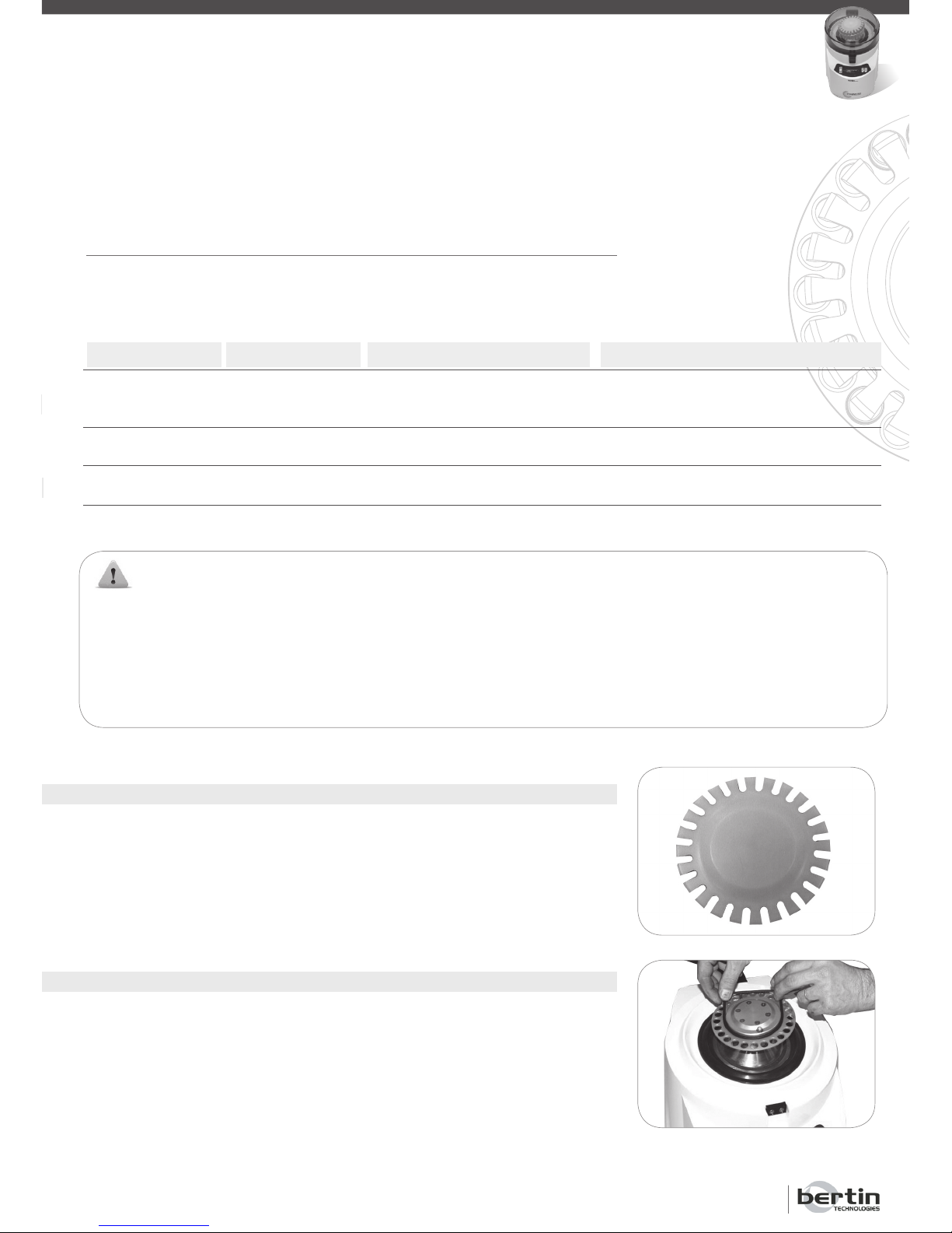
8.3 Replacing Spare Parts
This paragraph lists the maintenance actions to be done by user on a regular
basis, to ensure Precellys
®
24/Precellys®24-Dual runs properly.
Wearing parts are:
Wareing parts
Indented plate 24 tubes
Indented plate 12 tubes
Indented plate 6 tubes
Toric joint
Containment seal
Fuse
Reference
03119.810.NC002
03119.810.NC009
03119.810.NC010
03119.810.NC003
03119.810.NC004
03119.810.NC005
Frequency of replacement
1 year or to destruction
6 months or to destruction
1 year or to destruction
To destruction
Why?
Necessary to maintain tubes during
homogenisation.
Necessary to maintain tubes during
homogenisation.
Necessary to ensure the instrument’s
tightness.
-
8.3.1 Replacing Indented Plate
The indented plate can show signs of wear over time. Replace it once a
year.
8.3.2 Replacing Toric Joint
The toric joint located on the holder can show signs of wear over time. It
should be replaced when the “Pressure Alarm” message is displayed permanently. It is however recommended to replace it at least once every six
months.
Page 24
Precellys®24 & Precellys®24-Dual
Page 24
USER MANUAL
MAINTENANCE
8.4 Service Menu
8.4.1 Information Available
The unit firmware gives access to a “Service” menu presenting the following
information, useful for maintaining the system:
• VERSION: Firmware version.
• CPT: Cycle’s absolute counter devide: accumulated number of cycle done
by the unit.
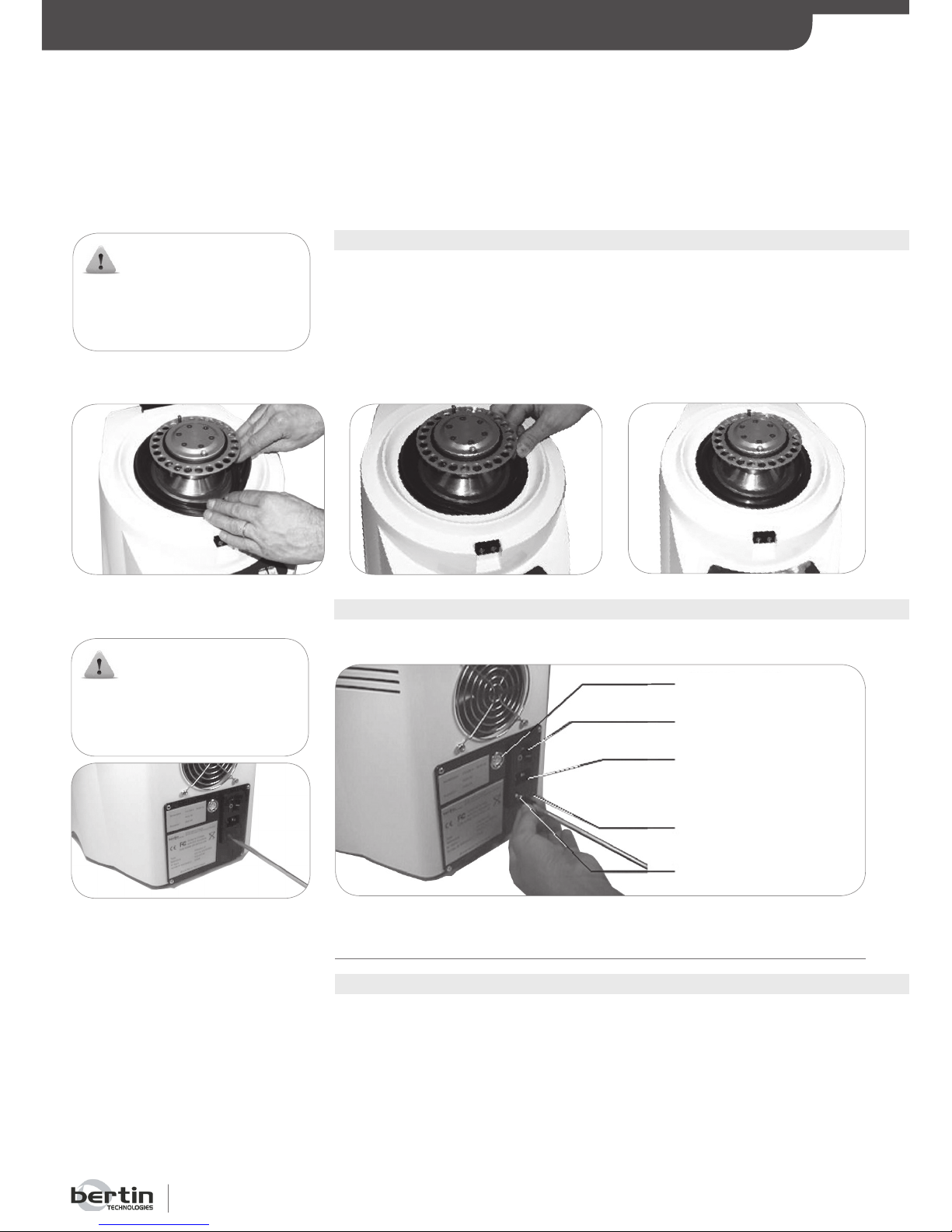
8.3.3 Replacing Containment Seal
The containment seal should be replaced at least once a year. It does not
require the dismantling of the holder.
1. Insert the interior part of the containment seal onto the metallic
edge.
2. Insert the exterior part of the containment seal onto the casing.
8.3.4 Replacing fuse
A screwdriver is required to replace the fuse.
Maintenance plug
On / Off button
Main power supply plug
120V / 240V switch
Fuse
WARNING:
Turn off the system and unplug
power cord before replacing the
containment seal.
WARNING:
Turn off the system and unplug
power cord before replacing the
fuse.
Page 25
Page 25
MAINTENANCE
• TIME: Running time absolute counter device: time associated to the number
of cycle run by the unit (running total only during cycle duration).
• RESET: Reset: the cycle counter device and the associated running time
counter device when the unit is switched on (see § 5.2.2) can be reset after
each system maintenance.
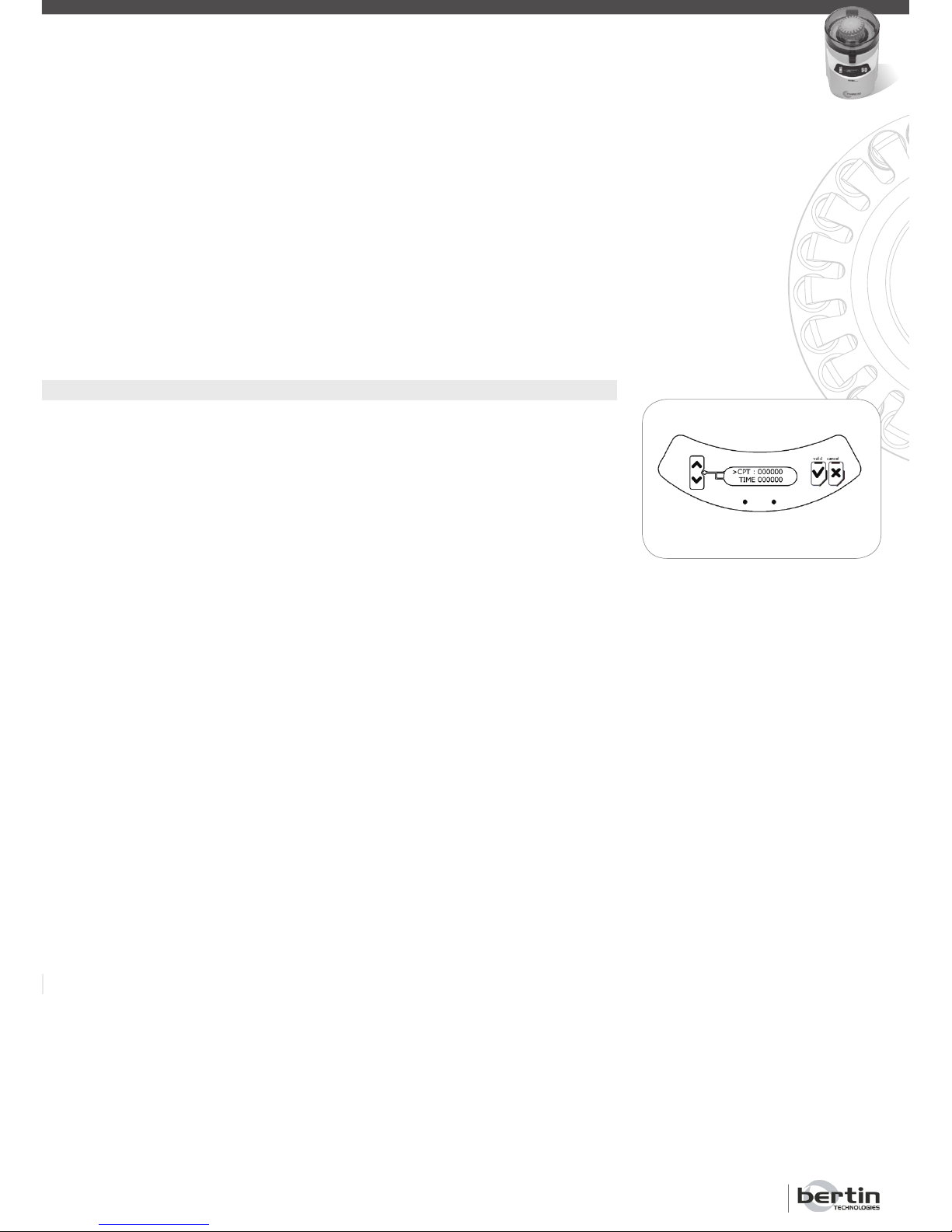
8.4.2 Acces to Service Menu
To access service menu, from the main menu, the user pushes the “Cancel”
button for approximately 5 seconds.
The service menu is an unwind menu on 4 lines, the screen displays 2 lines at
a time. “Up” and “Down” buttons move selection cursor in this menu:
To reset all counter devices, the user can choose the RESET line on the menu
with the cursor and must push the “Valid” button. The system starts again
and return to the main menu.
To exit service menu without resetting counter devices, the user must push
the “Cancel” button (whatever line is selected).
Page 26
Precellys®24 & Precellys®24-Dual
Page 26
USER MANUAL
9. Reparation / Elimination
9.1 Reparation
The equipment must be cleaned and decontaminated according to the procedure 8.1 before each shipment for reparation.
The equipment must be sent with a return slip indicating at least clearly the
used procedure the involved persons and the date of cleaning and decontamination operations.
In case that the return slip is missing, the equipment will be not taken in
charge by the customer service of Bertin Technologies.
The return slip is presented in the following page
9.2 Elimination
The cleaning and decontamination procedure described in 8.1 is obligatory
before putting the equipment to the rubbish in order to guarantee the persons
and the environment protection.
The equipment is covered by separate collection according to the directive on
waste electrical and electronic equipment (WEEE) 2002/96/EC.
REPARATION / ELIMINATION
Page 27
Page 27
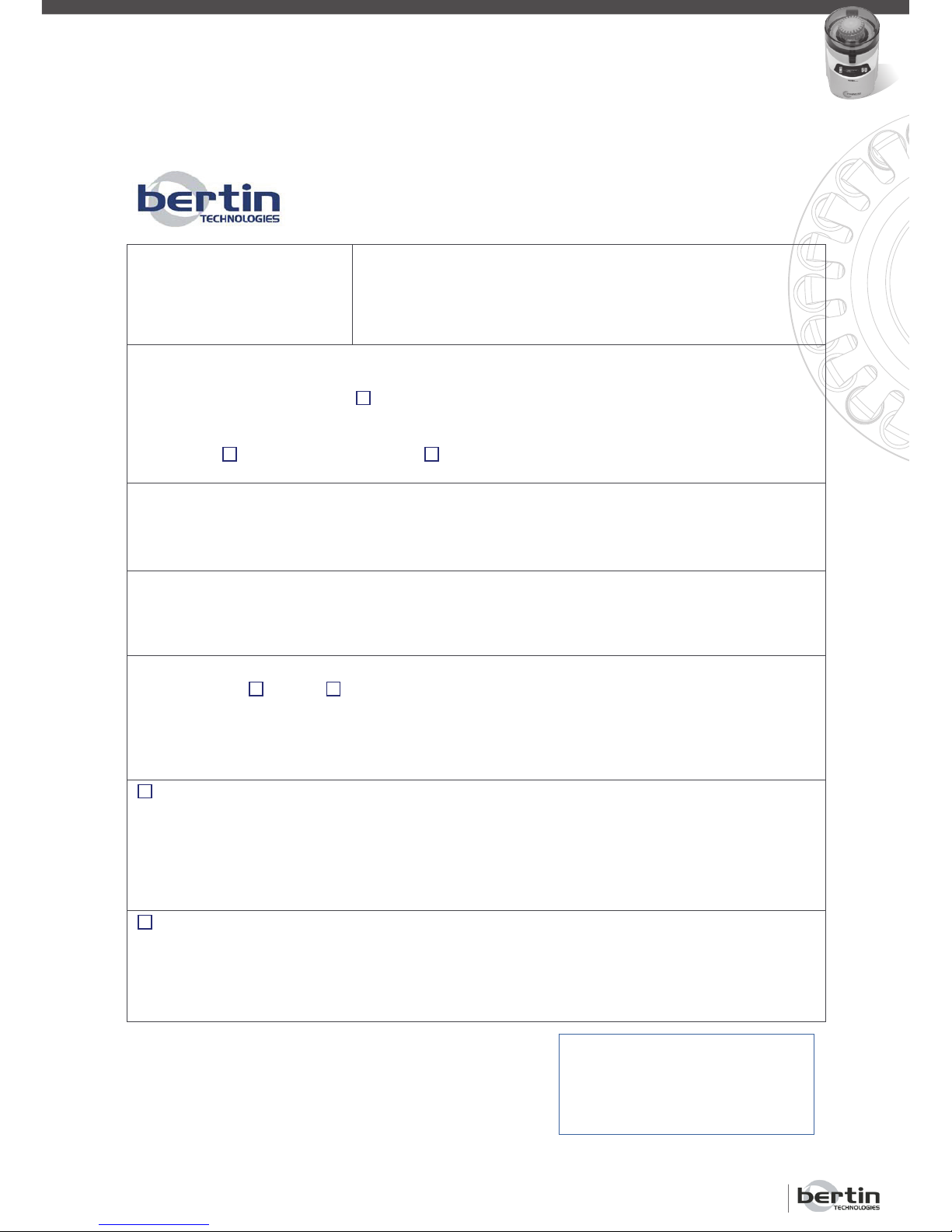
Return slip
Precellys 24
Returned the …… / …… / by: …………………………………
Address of the sender: ………………………………………………….
…………………………………………………………………….
Returned equipment:
Precellys 24
Associated equipment
User manual
Others (specify) : ………………………………………
Reason of return
……………………………………………………………………………………………………………………………
…………………………………………………………………………………………………………………………...
Detailed description of the technical issue
……………………………………………………………………………………………………………………………
……………………………………………………………………………………………………………………………
……………………………………………………………………………………………………………………………
Was the equipment been exposed to pathogen in the case of a biological risk caused?
YES NO
If yes, specify the class and the type
If yes, specify the section of obligatory decontamination below
In each case, specify the cleaning certificate below
Decontamination (Obligatory in case of exposition with pathogen about a
biological risk caused)
We attest that the decontamination of the equipment was been realised according to the
decontamination procedures of the user manual
Cleaning done the: …... / …... / …….
Cleaning certificate (Obligatory in each case)
We attest that the equipment was been submit to the cleaning operations described in the user
manual
Cleaning done the: …... / …... /……..
“We attest be notified that a wrong declaration can expose us to legal
proceedings where our responsibility can be engaged”
Written by:
By:
Function:
Date and Sign
Page 28

Precellys®24 & Precellys®24-Dual
Page 28
USER MANUAL
COPYRIGHT© BERTIN TECHNOLOGIES Tel: + 33 (0)1 39 30 60 00 - Graphic Design: www.idsg.fr
 Loading...