

BERTHOLD TECHNOLOGIES LB4710-050, LB4710-060, LB4710-160, LB4710-080, LB4710-090 User Manual
...
Process Control
Limit Switch
Mini-Switch LB 471
Hardware Manual
ID No. 39505 BA2
Rev. No.: 03 17. Nov. 2015
Soft. Version: 1.12 or higher
detect and identify
User’s Guide


The units supplied should not be repaired by anyone other than Berthold Service engineers or technicians by Berthold.
In case of operation trouble, please address to our central service department.
The complete user’s guide consists of two manuals, the hardware description and the software description.
The hardware manual comprises:
mechanical components
assembly
electrical installation
radiation protection guidelines
technical data
electrical and mechanical drawings
The software manual comprises:
operation of the evaluation unit
parameter description
basic setting
calibration
error messages
The present manual is the hardware description.
Subject to change in the course of further technical development.


Table of Contents
5
Table of Contents
Page
Chapter 1. General Information 9
1.1 Use and Function 9
1.2 Target Group 9
1.3 Radiation Protection Courses 10
1.4 Definitions 10
1.5 Safekeeping of the User’s Guide 12
Chapter 2. Safety 13
2.1 Safety Concept 13
2.2 Symbols and Pictograms 13
2.3 Radiological Safety Officer 14
2.4 Duty of Notification 14
2.5 Radiation Protection Areas 15
2.5.1 Exclusion Areas 15
2.5.2 Controlled Areas 15
2.5.3 Monitoring Areas 16
2.6 Safety Installations 17
2.6.1 Source Shieldings 17
2.7 General Safety Instructions 19
2.8 Emergency Instructions 19
2.8.1 Theft Protection 20
Chapter 3. Functional Safety 21
3.1 Use and Function 21
3.2 Safety Function 22
3.3 Safety Requirement 22
3.4 Project Planning 22
3.5 Getting Started 24
3.6 Behavior during Operation and Malfunctions 28
3.7 Recurrent Performance Test 29
3.8 Safety-Technical Data 29
Chapter 4. Instrument Description 36
4.1 Function 36
4.2 Mini Switch LB 471 Versions 37
4.2.1 Type Code 39
4.3 Detectors 40
4.3.1 GM Detector 40
4.3.2 NaI Detector 41
4.3.3 Super-Sens Detector 43
Chapter 5. Installation 45
5.1 Transport to the Installation Site 45
5.1.1 Transporting Detector and Evaluation Unit 45
5.1.2 Transport Shielding with Source 45
Mini-Switch LB 471

Table of Contents
6
5.1.3 Temporary Storage of Sources 46
5.1.4 Installation Site 46
5.1.5 Unpacking and Cleaning System Parts 46
5.2 Installing the Detector 47
5.2.1 Fastening Clamps for GM Detectors and NaI Counters 48
5.2.2 Stainless Steel Detector Holder (Alternative) 48
5.2.3 Installation of the GM Detector 49
5.2.4 Installation of the GM Detector 51
5.2.5 Installation of Super-Sens with Axial Irradiation 54
5.2.6 Installation of Super-Sens with Radial Irradiation 56
Chapter 6. Water Cooling 59
6.1 Subsequent Installation of Water Cooling (Option) 61
6.1.1 Water Cooling for NaI Detector with Collimator 62
6.1.2 Water Cooling for NaI Detector with Collimator 64
6.1.3 Water Cooling for GM Detector 65
6.2 Amount of Cooling Water Required 66
Chapter 7. Shielding Installation 67
7.1 General Installation Instructions 67
7.2 Installation Proposal for Shielding 68
7.3 Pneumatic Shielding Shutter (Option) 70
Chapter 8. Electrical Installation 71
8.1 Connecting Evaluation Unit and Detector 72
8.1.1 Pin Assignment of Terminal Block 73
8.1.2 Installing NaI Detector or Super-Sens 74
8.1.3 Installing the GM Detector 75
8.2 Digital In-/Outputs 77
8.2.1 Relays 77
8.2.2 Digital Input 77
8.3 Connecting the Evaluation Unit to Power 78
Chapter 9. Maintenance 79
9.1 Malfunctions 79
9.2 Replacing Fuses 79
9.3 Replacing the Evaluation Unit 80
9.4 Repairing the Detector 80
9.4.1 Dismantling the NaI Detector 81
9.4.2 Checking the Crystal-Multiplier Combination 84
9.4.3 Assembly of Crystal-Multiplier Combination 85
9.4.4 Plateau Measurement 86
9.4.5 Dismantling the GM Detector 87
9.5 Replacing the Source 88
9.5.1 Replacing the Source 90
9.6 Customer’s Service 92
9.6.1 Sending in the Electronics 93
9.6.2 Sending in Source and Shielding 94
Mini-Switch LB 471

Table of Contents
7
Chapter 10. Servicing the Shielding 95
10.1 Checking Shielding and Source 95
10.1.1 Testing the Locking Mechanism 95
10.2 Leak Test 96
10.2.1 Leak Test Documentation 96
10.2.2 Performing a Wipe Test 97
Chapter 11. Radiation Protection 99
11.1 Basics and Directives 99
11.2 Radiation Dose Calculations 101
11.3 Calculation with a given Dose Rate 101
11.4 Activity-based Calculation 102
Chapter 12. Disposal 103
Chapter 13. Technical Data 105
13.1 Evaluation Unit 105
13.2 Detectors 106
13.3 Shieldings 108
13.4 Pneumatic Locking Drive 108
Chapter 14. Certificates 109
14.1 ATEX Certificate for Evaluation Unit LB 4710-XXX 109
14.2 ATEX Certificate NaI Detector 113
14.3 ATEX Certificate GM Detector 117
14.4 EC Declaration of Conformity 119
Chapter 15. Technical Drawings 121
15.1 NaI Detector 121
15.2 GM Detector 122
15.2.1 Fastening Clamps 123
15.2.2 Detector Holder for GM Detector and NaI Counter 124
15.3 Super-Sens Detectors 125
15.4 Point Source Shielding LB 744X 131
15.5 Dimensions of the Evaluation Unit 134
15.5.1 19" Rack 134
15.5.2 Wall Housing 135
15.5.3 Cassette 136
15.6 Connection Diagrams 137
15.6.1 19" Rack 137
15.6.2 Wall Housing 138
15.6.3 Cassette 139
15.6.4 Connection Diagram for Power Supply Unit in 19" Rack 140
Mini-Switch LB 471


Chapter 1 General Information
9
Qualification
Training
Chapter 1. General Information
1.1 Use and Function
The limit switch system LB 471 Mini Switch has been designed for
monitoring and detection of levels in containers and pipelines.
Licensed as an “overflow protection device for containers storing
liquids that are hazardous to waters” in accordance with the Water
Resources Act, the system may also be used as overflow protection device.
Beyond this scope, each application is considered as not being in
compliance with the law and may result in severe personal injury
or property damage.
BERTHOLD TECHNOLOGIES does not assume any liability for this kind
of injuries or damage.
1.2 Target Group
This user’s guide has been written for operating, assembly and
service personnel.
The system may only be assembled, serviced and maintained by
authorized and trained persons. Any modification of the settings
may only be carried out by persons who are familiar with the function of the system. Persons working with ionizing radiation must be
familiar with the rules of radiation protection and adequate work
techniques.
Personnel have to be specially trained and informed about possible
hazards. Detailed knowledge of this user’s guide and careful observation of the instructions contained therein is an essential prerequisite.
Each staff member has to know the major rule of the “ALARA principle” (as low as reasonably achievable).
BERTHOLD TECHNOLOGIES is offering appropriate training courses.
Depending on the participant’s professional qualifications, two
kinds of training can be chosen:
Mini-Switch LB 471

Chapter 1 General Information
10
Automatic
Some parameters can either be set to the automatic or manual
mode. In the automatic mode the value is calculated using a
formula. Enter -1 to enable the automatic mode. The inverted C
in the top row indicates whether a parameter has been set to
automatic.
EVU
Evaluation Unit
Edit
Change value
Edit mode
In this mode, a value can be changed. Not every parameter can
be changed since some parameters are only used as display
values. Editable Parameters can be set to the edit mode with
the “Enter” button. In the edit mode the cursor positioned over
a digit is flashing.
GM detector
Detector with Geiger-Müller counter tube
NaI detector
NaI = sodium iodine crystal = scintillator
Scintillation detectors are very sensitive to Gamma radiation.
See pages 40 and 121.
Super-Sens detector
Detector which is highly sensitive to Gamma radiation with
large-volume plastic scintillator 150x150mm
See pages 43 and 125.
Limit value
Count rate or percentage value upon reaching the measurement level
1.3 Radiation Protection Courses
Special course in radiation protection
(Duration: 2 days)
This course is needed if the participant has not yet received any
radiation protection training. A successfully completed course
has a validity of 5 years.
Refreshing course in radiation protection
(Duration: 1 day)
All persons who have already successfully completed the special course may refresh their special knowledge with this course
(Radiation Protection Ordinance of August 1, 2001).
A successfully refreshing course has a validity of 5 years.
1.4 Definitions
Mini-Switch LB 471

Chapter 1 General Information
11
HV
Detector high voltage
Cassette
Case (7 TE) into which the evaluation unit LB 4710 is installed,
so it can be used in any 19" rack
Empty
Level below limit value.
Empty count rate
Count rate with empty container
Manual
Some parameters can either be set to the automatic or manual
mode. For the manual mode you have to enter a fixed value in
the respective parameters.
Nuclide / Isotope
Type of radiation source: Cobalt-60 (Co-60) or Cesium-137
(Cs-137) for level measurements.
Zero count rate
Count rate caused by natural environmental radiation.
Parameters
A value stored under a certain code.
Timeout
Time after which an automatic reset is performed.
Full
Level below limit value.
Full count rate
Count rate with full container.
Count rate
Value of counts relative to one second.
cps
Count rate unit: Counts per second.
Read in count rate
A process that is started by the user in order to determine the
average value of the count rate at the respective level. This
count rate is needed to calibrate the measurement. The count
rate is averaged over a certain time (standard 60 s) to exclude
statistical and process-immanent fluctuations.
Factory setting
All parameters have been preset by the manufacturer using
standard values. In most cases this simplifies calibration of the
instrument significantly. Despite factory setting, calibration al-
ways has to be performed.
mSv
Dose rate unit
Millisievert
Mini-Switch LB 471

Chapter 1 General Information
12
MBq
Mega-Becquerel
This unit indicates the source activity. Each Bq corresponds to
one decay per second..
1 MBq = one million decays
mCi
Milli-Curie
This unit is also used for the activity of a source. However, this
unit has been replaced by the unit MBq (1mCi = 37 MBq)
Note!
This user’s guide always has to be available at a fixed place. The
personnel have to be informed about this place. Any time the device is used by another operator and whenever there is a change
in ownership of the device, the user’s guide has to be given to the
new operator or owner.
1.5 Safekeeping of the User’s Guide
Mini-Switch LB 471

Chapter 2 Safety
13
Danger!
Possible danger for life and health hazard
Caution!
Possible hazard
Minor personal injuries
Warning!
Possible hazard
Property damages
Note!
Tips for application and useful information
Chapter 2. Safety
2.1 Safety Concept
The state-of-the-art system is designed in accordance with accepted safety rules to ensure the greatest possible on-the-job safety.
To rule out health hazards when handling radioactive substances,
limit values stating the highest acceptable radiation exposure of
the operating personnel have been defined on an international level. These limits have to be observed when designing shieldings and
planning the configuration of the measuring system at the measurement point.
2.2 Symbols and Pictograms
The following symbols identify safety instructions in this user’s
guide:
The safety instructions are supplemented by explanatory pictograms, for example:
Mini-Switch LB 471

Chapter 2 Safety
14
Caution!
Radioactivity!
In case of suspected damage to the shielding, the radiological
safety officer has to be informed immediately. Further steps can
be taken in consultation with BERTHOLD TECHNOLOGIES.
2.3 Radiological Safety Officer
To ensure proper handling and the observance of the statutory
requirements the operating company has to appoint a radiological
safety officer who is in charge of all radiation protection issues in
connection with the measuring system.
The radiological safety officer has to:
monitor working with the radiometric measuring system
draw up a plan for the organization of radiation protection
monitor compliance with the regulations of the Radiation Pro-
tection Ordinance
issue directives and carry out training and instruction of the
employees
get on-site information on the situation and takes appropriate
actions immediately if operation problems have occurred
cooperates with the work’s council or the personnel office and
qualified personnel for on-the-job safety, advises and informs
them on important radiation protection issues.
2.4 Duty of Notification
Mini-Switch LB 471

Chapter 2 Safety
15
Caution!
Radioactivity!
The radiation protection directives have to be observed.
Exclusion areas have to be protected such that nobody has unchecked access to these areas – not even with single body parts.
This has to be ensured through constructive measures, for example by protective covers.
2.5 Radiation Protection Areas
Radiation protection areas define the boundaries around a radiation source. The maximum dose rate defines the limit. We distinguish three radiation protection areas:
2.5.1 Exclusion Areas
Exclusion areas are areas in which the local dose rate may be exceed 3 Millisievert (mSv) per hour. These areas have to be protected such that nobody has unchecked access to these areas –
not even with single body parts. Actually, these areas can occur
only in the active beam in the direct vicinity of the shielding.
2.5.2 Controlled Areas
Controlled areas are areas in which persons in one calendar year
may receive an effective dose of more than 6 mSv if they stay in
this area 40 hours a week and 50 weeks per calendar year. Based
on this, the calculated maximum dose rate is 3 µSv/h. These areas
should be planned such that accessibility is virtually not possible or
that the required safety fences can be installed easily. If con-
trolled areas are accessible they have to be secured. Moreover, they have to be identified clearly and permanently by a radiation danger sign and the comment “Controlled Area”. Persons may
access controlled areas only to carry out maintenance work for the
operations going on inside this area (§ 37). Body doses have to be
calculated or personal doses have to be measured. The authorities
may permit exceptions from the demarcation and identification
duty, provided individuals or the general population are not endangered. Higher limit values are admissible if reliable in-
formation is provided that the person affected stays within
the controlled area for a shorter period of time.
Mini-Switch LB 471

Chapter 2 Safety
16
Caution!
Radioactivity!
The radiation protection directives have to be observed.
Controlled areas outside the shielding have to be identified and
secured if they are accessible.
2.5.3 Monitoring Areas
Monitoring areas are operation areas which do not belong to the
controlled area. In these areas, a person may receive an effective
dose of more than 1 mSv in one calendar year.
The monitoring area starts at the controlled area. It is an area in
which persons staying permanently in this area may be exposed to
a radiation level of more than 1 mSv in one calendar year. For a
stay of 40 hours per week and 50 weeks per year the area is between the dose rate limit values of 3 µSv/h and 0.5 µSv/h. It has
to be ensured that persons are not exposed to a dose exceeding
1 mSv per year, taking into account the actual time they stay in
this area. This means that no permanent work place may be set up
in this area.
Mini-Switch LB 471
Chapter 2 Safety
17
Caution!
Radioactivity!
The shielding with the source installed may be taken into operation by specially licensed persons who have been trained on handling radioactive materials only after consultation and coordination
with the radiological safety officer.
The radiation exit channel must only be opened by authorized persons after consultation with the radiological safety officer.
Modification of or tampering with the shielding construction are
prohibited.
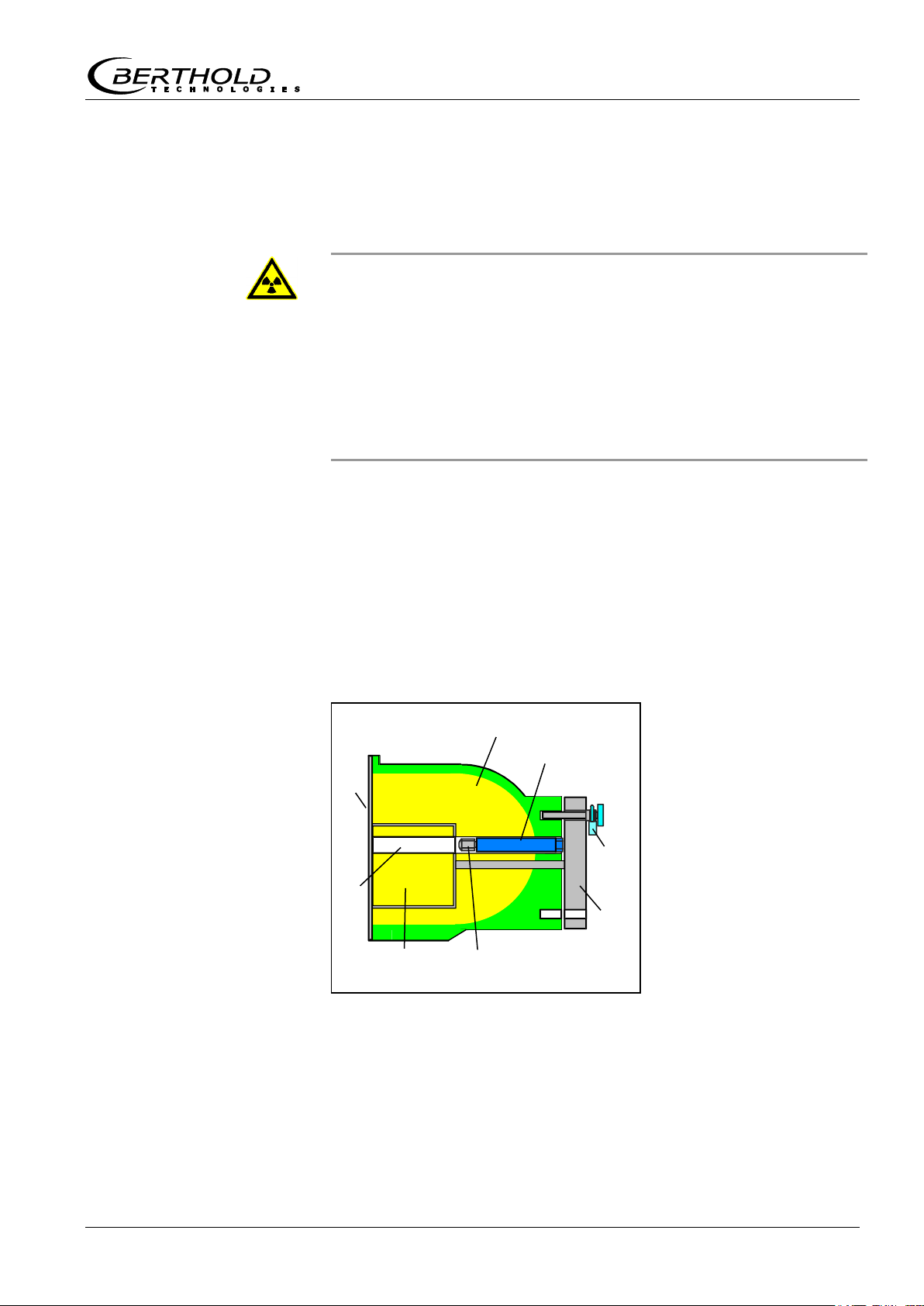
Shielding
Locking core
Radiation channel
Point sources
Source holder
Lever
Padlock
Cover plate front
Source
Shielding
Figure 1:
Point source shielding
radiation channel open
Sectional drawing
2.6 Safety Installations
2.6.1 Source Shieldings
Co-60 or Cs-137 point sources are used for the system. They
are tightly welded into a sturdy stainless steel capsule, so that the
radioactive substance cannot escape and contamination is prevented. The capsule with the source is fixed on a holder and
installed into the shielding.
The shielding consists of a lead cylinder with radiation exit channel
, surrounded by a steel jacket. The locking core is fixed to a
lever . The padlock secures the open / closed position and
protects the source against unauthorized removal.
When turning the lever , the locking core is rotated as well and
the radiation exit channel is opened towards the detector. The arrow on the lever is pointing towards “OPEN”.
Mini-Switch LB 471

Chapter 2 Safety
18
Lever with arrow
Padlock
Cover plate rear
Source number
Activity
Isotope
Source manufacturing
date
Dose rate in
1m distance
Effective shielding
thickness
Shielding material
Type of shielding
Shielding manufacturer
Figure 2:
Shielding
- view of lock
Type label
Figure 3:
Type label
on shielding
Strahler-Nr.:
1234 - 11- 9 4
MBq
Co-60
400
Abschirmung
mm
Datum
12. 11.94
Pb
98
Dosisleistung in 1m Abstand
5
Sv/h
MODEL LB 7440
Bad Wildbad D-75323
The radiation exit channel has to be closed during transport, assembly and while carrying out work on the container.
The arrow on the lever is then pointing to “CLOSED”.
The lever or the locking core is secured by a padlock in the
“OPEN” and in the “CLOSED” position.
Shielding, radiation type, isotope and activity have to be selected
for each measuring configuration such that the internationally
permissible dose rate limits will not be exceeded.
The source and shielding version is documented in the supplied
technical source documentation and on the type label on the
shielding.
Mini-Switch LB 471

Chapter 2 Safety
19
Caution!
The safety instructions in this user’s guide have to be observed
without fail.
All laws, directives, accident prevention regulations and generally
accepted safety regulations have to be complied with!
The system may be used only in technically good order and only
for contractual use!
Only persons may work with the system who have been authorized to do this and who have the proper qualification and have
received the necessary instructions!
Installations and modifications on the system which may affect the
operational safety are prohibited!
Danger!
Hazard due to radiation damages.
Never touch the source with your hands!
2.7 General Safety Instructions
2.8 Emergency Instructions
The following basic principles are indispensable for health and
safety: Time, distance and shielding. In an emergency, the following provisions have to be taken:
Restrict access to this area, identify radiation protection areas.
Check the function of the shielding and measure the dose rate.
Localize the source.
Document the event and, if possible, estimate the potential
radiation exposure of the persons involved.
Report event to BERTHOLD TECHNOLOGIES.
In case of loss of radiation sources, the regulatory agency has
to be notified immediately.
In case of suspected damage to the source capsule the follow-
ing issues have to be taken into consideration:
Grasp source with a tool (e.g. a pair of pliers or tweezers) and
put both (source and tool) into a plastic bag.
Place plastic bag behind an auxiliary shielding (concrete wall,
steel or lead plate).
Check if environment is free of contamination.
If a source has any leaks or if you suspect that the permissible
dose has been exceeded, the regulatory agency has to be notified immediately.
Mini-Switch LB 471

Chapter 2 Safety
20
2.8.1 Theft Protection
Radioactive substances or facilities containing radioactive substances have to be secured such that they are protected against
access by unauthorized persons. If you discover that radioactive
substances are missing, you have to notify the radiological safety
officer and the regulatory agency. In case of theft, the police have
to be informed.
Please see Chapter 11 for more information on radiation protection.
Mini-Switch LB 471
Chapter 3 Functional Safety
21
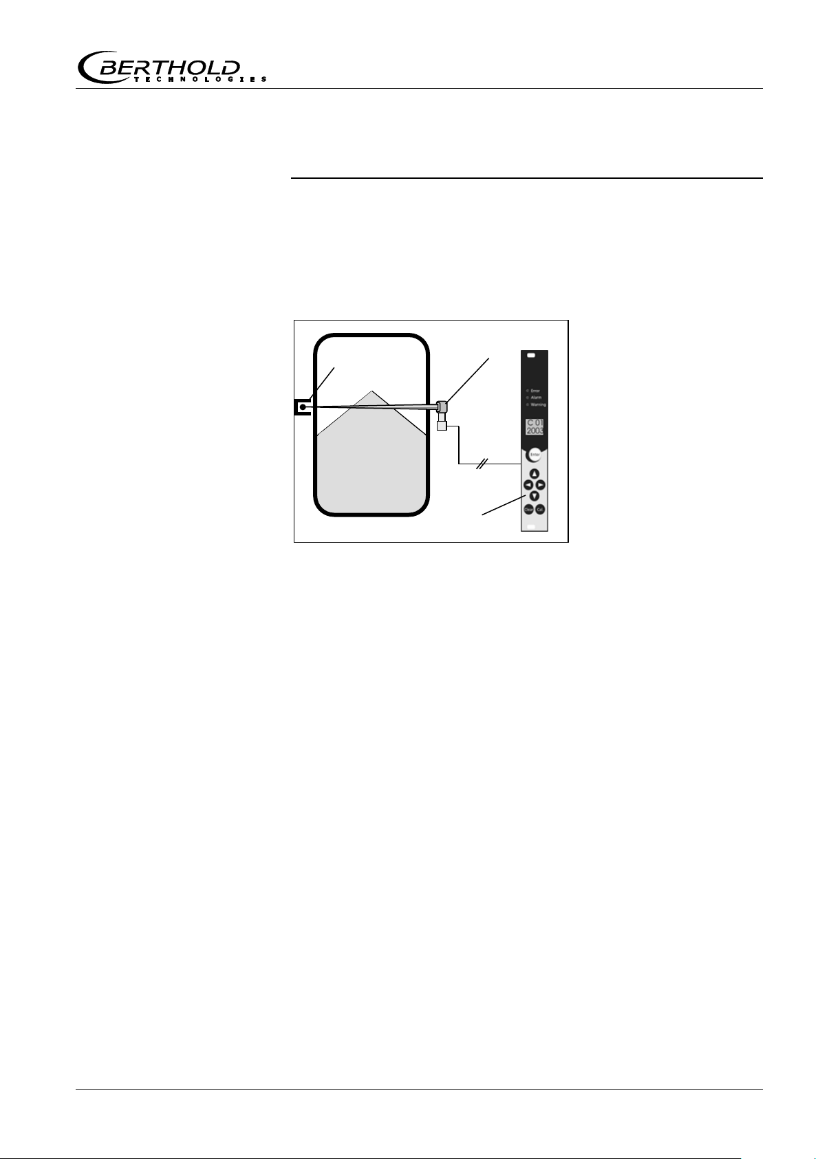
Source
Detector
Evaluation unit
Figure 4:
Measuring system
2 wires
Chapter 3. Functional Safety
3.1 Use and Function
The LB 471 Mini Switch is employed for monitoring and detection
of the limit levels of liquids and bulk material in containers and
pipelines.
The measuring system can be employed for the detection and indication of maximum levels (overflow protection) and minimum levels (protection against dry running) and fulfills the requirements
regarding:
Explosion protection (depending on version and category),
Water Resources Act (overflow protection device for containers
storing liquids that are hazardous to waters),
Electromagnetic compatibility according to EN 61326 and Na-
mur NE 21.
If the device is employed in safety-relevant systems (functional
safety according to IEC 61508/61511), all information in this
User's Manual has to be observed. In particular, the safetytechnical data in section 3.8 apply only to the application of the
system in the operating mode with low demand mode and taking
into account the information in this manual.
Beyond this scope, each application is considered as not being in
compliance with the law and may result in severe personal injury
or property damage.
BERTHOLD TECHNOLOGIES does not assume any liability for this kind
of injuries or damage.
Mini-Switch LB 471

Chapter 3 Functional Safety
22
Safety integrity
level
Operating mode with
low demand rate
Operating mode with high
or continuous demand rate
SIL
PFD
avg
PFH
4
≥10-5 to <10-4
≥10-9 to <10-8
3
≥10-4 to <10-3
≥10-8 to <10-7
2
≥10-3 to <10-2
≥10-7 to <10-6
1
≥10-2 to <10-1
≥10-6 to <10-5
Safe failure fraction
Hardware fault tolerance
SFF
HFT = 0
HFT = 1
HFT = 2
none: <60%
not allowed
SIL 1
SIL 2
low: 60% to <90%
SIL 1
SIL 2
SIL 3
medium: 90% to <99%
SIL 2
SIL 3
high: ≥99%
SIL 3
General instructions and
restrictions
3.2 Safety Function
The safety function of the measuring system comprises the detection and indication of changes in the count rate of the detectors
caused by the presence of product being measured in the measuring path between radiation source and measuring system.
The safe status is dependent on the mode of operation:
Maximum level (overflow protection): Product between radia-
tion source and detector -> low count rate
Minimum level (protection against running dry): No product
between radiation source and detector -> high count rate
3.3 Safety Requirement
3.4 Project Planning
Please make sure that the measuring system will be used in
accordance with its designated function.
The application-specific limits have to be observed and the
specifications must not be exceeded. See also the technical data and ambient conditions in the User’s Manual.
The fault tolerance time of the overall system must be greater
than the reaction time of the measuring system.
The relay contacts have to be protected by a 1A fuse.
The digital inputs 1 and 2 must not be closed in case of a safe-
ty-related application.
Mini-Switch LB 471

Chapter 3 Functional Safety
23
Assumptions
Safe state and fault
description
Interfering radiation, e.g. due to welding seam tests, is largely
identified and signaled by the measurement. However, in some
situations it is conceivable that the intensity of the interfering
radiation will increase the radiation level at the detector only
slightly, so that no alarm is triggered or not in due time. Therefore, the facility always has to be informed as soon as a welding seam test is carried out in the environment of the facility in
which the measurement is employed. In this case, suitable
safety precautions have to be taken.
Interfering radiation from adjacent measuring points has to be
avoided.
The FMEDA (Failure Mode Effects and Diagnostics Analysis) is
based on the following assumptions:
The failure rates are constant over the service life of the de-
vice.
The following is not taken into consideration:
external power supply failure rates
multiple errors
operating mode as minimum level switch
The mean ambient temperature during the operating time is
40°C.
The environmental conditions correspond to those of an aver-
age industrial environment.
The working life of the components is between 8 and 12 years.
The time to repair (replacement of the measuring system) after
a fault protected from interference is eight hours (MTTR = 8h).
If the demand rate is not more than once a year, the measuring
system may be operated as a safety-relevant sub-system in the
operating mode with low demand rate (IEC 61508-4, 3.5.12).
Numerical values see section “Safety-Technical Data”.
The fail-safe state is reached when the current output indicates the
following values.
A safe failure is defined as a failure that causes the measuring system to go to the defined fail-safe state without a demand from the
process.
A dangerous undetected failure is present if the measuring system,
following a demand from the process, does not go to the defined
fail-safe state.
Mini-Switch LB 471

Chapter 3 Functional Safety
24
3.5 Getting Started
The conditions at the facility affect the safety of the measuring
system. Therefore, the mounting and installation instructions in
the User’s Manual have to be observed. In particular, the correct
setting of the parameters has to be ensured. For more information
on the parameters and on getting started, please refer to the User’s Manual LB 471 ID No. 39505BA2.
The device may be operated as safety-relevant only in the professional mode.
Reset
1
Keep Clear button pushed and turn the power supply on.
The device is reset to factory setting.
Basic parameter setting
Set parameters according to the following parameter list.
The order in which the parameters have to be set is shown
in the last column.
Fields that are not numbered in this column are display
parameters or parameters that remain on factory setting.
If the Value column includes data, then you have to enter
this data exactly.
If no data has been entered in the Value column but a
number has been entered in the last column, then the
value of the parameter has to be adapted to the given
measurement situation. However, the value has to be
adapted only if this is required by the measurement situation.
Mini-Switch LB 471

Chapter 3 Functional Safety
25
Code
no.
Designation
Value range
Factory
setting
Value
Order
00
Password
0000 - 9999
01
Year
1970 - 2099
Current
year
1
02
Month / Day
01.01-12.31
Current
date
2
03
Hour / Minute
00.00-23.59
Current
time
4 04
Operation mode
Standard/Professional
0 - 1
0
1
3
05
Detector code
0 - 99
99
5
06
Nuclide
0=Co60, 1=Cs-137
0 - 1
0
6
07
Automatic password
protection
0 - 9999
0
08
Warning relay as
second alarm relay
0 – 1
10 – 100
0
09
Alarm relay follows
the error relay
0 - 1
0
1
7
10
Reading (%)
-999 - 9999
Display
11
Average count rate
0 - 999.9
Display
12
Time constant (s)
0,1 – 999,9
-1
13
Live count rate
0 - 999.9
Display
14
Maximum time constant (s)
0 - 999
999
8
15
Standard reading
10 - 11
10
16
Max. or min. limit
value switch
0=Max, 1=Min
0 - 1
0
17
Switching threshold (%)
0 - 100
-1
18
Switching threshold in (cps)
0 - 999.9
-1
19
Hysteresis (%)
0 - 999
-1
20
Empty count rate (no input)
0 - 999.9
Display
21
Full count rate (no input)
0 - 999.9
Display
22
Zero count rate (no input)
0 - 9.999
Display
30
Empty count rate
0 - 999.9
20 GMZ
300 FSK
31
Full count rate
0 - 999.9
-1
32
Zero count rate
0 - 9.999
Depending
on detector
code
33
Measuring path (in mm)
0 - 9999
0
9
34
Gas density (kg/m³)
0 - 9999
0
10
35
Bulk density (kg/m³)
0 - 9999
0
11
36
Compute
35.01–35.08
Display
37
Counting time for
calibration (s)
5 - 600
60
12
38
Bulk cone diameter (mm)
0 - 9999
0
Table 1:
Code table
for professional mode
Mini-Switch LB 471

Chapter 3 Functional Safety
26
Code
no.
Designation
Value range
Factory
setting
Value
Order
39
Half-value layers
1 - 9
2
13
40
Interference radiation
detection
0 - 1
0
1
14
41
Waiting time after
interference radiation
0 - 999
20
15
42
Signaling interference
radiation
0 - 2
0
1
16
43
Signaling unlocked
0 - 2
0
1
17
44
Signaling minor errors
0 - 2
0
1
18
45
Signaling excess temp.
Detector (only FSK detector)
0 - 2
0
0
46
Temperature threshold
detector (only FSK)
0 - 99
40
47
Signaling excess temp.
EVU
0 - 2
0
1
19
48
Temperature threshold EVU
0 - 99
85
≤50
20
50
Limit switch software
1.00 - 9.99
Version
51
Detector software
(only FSK)
1.00 - 9.99
Display
52
Detector temperature °C
(only FSK detector)
-40 - 80
Display
53
Detector high voltage
(only FSK)
500 - 1300
-1
54
detector HV start value
(only FSK)
500 - 1300
HV default
55
Source replacement
00.00- 99.12
-1
56
Evaluation unit electronics
temperature
-100 - 200
Display
60
Test pulse generator
0 - 999.9
0
61
Test error relay
0 - 2
0
62
Test alarm relay
0 - 2
0
63
Test warning relay
0 - 2
0
64
Test display
65
Test keyboard
66
Status digital in
00.00 - 01.01
Display
67
HV max for plateau
measurement
500 - 1300
1000
68
Detector plateau
measurement
(only FSK)
0 - 5
0
70
Error log
0 - 1
0
71
Revision log
0 - 1
0
72
Save & Load / Reset
0 - 99
0
Mini-Switch LB 471

Chapter 3 Functional Safety
27
Empty calibration
The level must be at least 50 mm below the limit level. The
radiation channel of the shielding is open.
Push the “Cal” button for 3 seconds
The empty count rate is read in.
At the end of the measuring time, code 30 is displayed and
the read-in empty count rate.
Full calibration
The level must be at least 50 mm above the limit level.
If this is not possible, you may also close the source shielding. If only the source shielding is closed to carry out the
full calibration, then you have to keep in mind:
- Make sure that the absorption of the closed shielding
nearly corresponds to the absorption of the product. If in
doubt, please contact BERTHOLD TECHNOLOGIES or your local
representative.
- Typically, you will lose some dynamics in the measurement, which results in a higher time constant.
Select code 31.
Push the Enter button
Push the Cal button.
The full count rate is read in.
At the end of the measuring time, code 31 is displayed and
the read-in full count rate.
Calibration
Select code 36.
Push the Cal button.
A checkmark and the digits 0000 confirms that the calibra-
tion was successful.
If an error message is display, the error has to be removed
as described in the User's Manual and in the error list; then
the calibration has to be carried out once more.
Test
Write down the empty and full count rate in code 30 and
code 31.
Select code 60.
Enter the full count rate in code 60.
The measurement must show 0% in code 10.
If not, check the calibration.
Select code 60.
Enter the full count rate in code 60.
The measurement must show 100% in code 10.
If not, check the calibration.
Mini-Switch LB 471

Chapter 3 Functional Safety
28
Function check
Level is at least 50mm below the limit level when the radia-
tion channel of the shielding is open.
The measured value in code 10 has to fluctuate around 0%.
The alarm output must not trigger an alarm.
Increase the level above the limit level or close the shield-
ing.
The measured value in code 10 has to fluctuate around
100%. The alarm output must indicate an alarm and must
not switch back anymore.
Password
Enter a password in code 00.
This rules out data manipulation by unauthorized persons.
The error relay switches to normal only when the password
has been entered and no error message is output.
The calibration is now finished and the measurement has been
taken into operation.
3.6 Behavior during Operation and
Malfunctions
The following parameter are automatically adjusted in the
course of operation relative to the decay compensation; therefore, their values may change: code 12 and code 18 – 31
If the operation is changed, please observe the safety func-
tions.
Malfunctions that may occur are described in the User’s Manu-
al.
If failures have been detected or malfunctions are reported,
you have to take the entire measuring system out of service
and keep the process in a safe state through other measures.
Replacement of the measuring system is rather simple; it is
described in the User’s Manual.
If parts are replaced as a result of a detected failure, please
inform BERTHOLD TECHNOLOGIES (including failure description).
If modifications in the product, the gas pressure, or the con-
struction of the tank in the area of the radiation path are carried out, the measurement has to be calibrated again.
Mini-Switch LB 471

Chapter 3 Functional Safety
29
λsd
230 Fit
safe detected failure (1 FIT = failure/109h)
λsu
536 Fit
safe undetected failure
λdd
210 Fit
dangerous detected failure
λdu
83 Fit
dangerous undetected failure
SFF
>92%
Safe Failure Fraction
T
Reaction
Failure reaction time
1.5 sec
max. service life of the measuring system for the
safety function.
7 years
General data
3.7 Recurrent Performance Test
The recurrent performance test is used to check the safety function to uncover possibly undetected dangerous failure. The operational capability of the measuring system has to be checked in adequate intervals.
It is in the responsibility of the operator to select the type of test
and the proof test interval. The intervals are dependent on the
PFD
Technical Data” (see also FMEDA Report).
The test has to be carried out such that the proper safety function
will be proven through interaction of all components.
This is the case when the level is controlled within the scope of a
filling. If a filling is not feasible, the measuring system has to be
triggered to respond by suitable simulation of the level or of the
physical measurement effect.
The methods and procedures used in the tests have to be named
and their degree of suitability has to be specified. The tests have
to be documented.
If the function check is negative, you have to take the entire
measuring system out of service and keep the process in a safe
state through other measures.
value defined in the table and chart in the section “Safety-
avg
3.8 Safety-Technical Data
Failure rates of the electronics were determined through FMEDA
according to IEC 61508. Calculations are based on the component
failure rates according to SN 29500. All numerical values refer to
an average ambient temperature of +40°C (104°F) during the operating period. Calculations are further based on the information
provided in chapter 3.4 Project Planning.
Mini-Switch LB 471

Chapter 3 Functional Safety
30
PFD
avg
T
Proof
= 1 year
T
Proof
= 2 years
T
Proof
= 5 years
T
Proof
= 10 years
<0.036 x 10
-2
<0.073 x 10
-2
<0.180 x 10
-2
<0.360 x 10⁻²
PFD
avg
T
Proof
= 1 year
T
Proof
= 2 years
T
Proof
= 5 years
T
Proof
= 10 years
<1.8 x 10
-5
<3.7 x 10
-5
<9.5 x 10
-5
<20 x 10-5
PFD
avg
T
Proof
= 1 year
T
Proof
= 2 years
T
Proof
= 5 years
T
Proof
= 10 years
<3.7 x 10
-5
<7.3 x 10
-5
<19 x 10
-5
<38 x 10-5
Detector
Evaluation units
Container
Shielding with
source
Detectors
Evaluation units
Container
Shielding with
source
Single channel architecture
HFT = 0 (Hardware Fault Tolerance)
Two-channel architecture
HFT = 1 (Hardware Fault Tolerance)
1) for Common cause ß=5%
2) for Common cause ß=10%
Mini-Switch LB 471

Chapter 3 Functional Safety
31
Time-dependent
trend of PFD
avg
PFD
avg
T
Proof
1 5 10 1 2
3
4
The time trend of PVD
is nearly linear to the operating time in
avg
the period up to 10 years. The above mentioned values apply only
to the T
interval, according to which a recurrent performance
Proof
check has to be carried out.
Time-dependent trend of PFD
avg
Mini-Switch LB 471


Chapter 3 Functional Safety
33
Mini-Switch LB 471

Chapter 3 Functional Safety
34
Mini-Switch LB 471

Chapter 3 Functional Safety
35
Mini-Switch LB 471

Chapter 4 Instrument Description
36
Figure 5:
Measuring system
2 wires
Chapter 4. Instrument Description
4.1 Function
The limit switch system Mini Switch LB 471 is working on the basis
of non-contact Gamma absorption measurement. The system can
also be employed with heavy process conditions and aggressive
media.
In order to obtain an optimum measurement effect at minimum
source activity the best measurement geometry is calculated for
the respective measuring point and the source is designed on the
basis of this calculation.
The system comprises three major components:
shielding with radiation source
Detector
evaluation unit .
The shielded radiation source is installed outside the container
on the level to be measured. A detector is installed on the opposite side of the container. The evaluation unit is connected to
the detector by a 2-wire line.
If the level of the medium inside the container comes up to the
level of the detector or the source, the radiation is absorbed and
the evaluation unit sends a corresponding signal.
The following radiation sources are used:
Mini-Switch LB 471

Chapter 4 Instrument Description
37
Caution!
Observe explosion protection!
Intrinsically safe and not intrinsically safe systems must not be
mixed, neither in a 19" rack nor in a wall housing.
In a 19" rack
Co-60 has a relatively high energy of 1.17 or 1.33 MeV and is
used on very thick pipeline or container walls. Its half-life time
is 5.27 years.
In most cases, Cs-137 with an energy of 0.660 MeV is ade-
quate to irradiate common pipeline or container walls. Its halflife time of Cs-137 is around 30 years.
Due to the lower energy, operating expenses for shielding a
Cs-137 source are lower than for Co-60.
4.2 Mini Switch LB 471 Versions
The Mini Switch LB 471 can either be delivered in a 19" rack, in a
wall housing or in a cassette.
The 19" rack can be mixed with limit switches for GM detectors
and fitted for NaI detectors. The 19" rack includes a back plane.
A filter module is used (for max. 19 limit switch modules) for
24V AC/DC supply. It includes:
one mains switch
on mains On LED
two fuses (see Technical Data on page 105)
additional filter section
A 85W transformer module is used (for max. 18 limit switch
modules) for 115/230V supply. In addition to the filter module, the
transformer module has:
a transformer with voltage selector switch 115V/230V
Mini-Switch LB 471

Chapter 4 Instrument Description
38
for any 19" rack
In a wall housing
As cassette
Front view Side view
The wall housing can be mixed with limit switches for GM detectors
and fitted for NaI detectors. The wall housing includes a back
plane.
A filter module is used for 24 V AC/DC supply. It includes:
one mains switch
on mains On LED
two fuses (see Technical Data on page 105)
additional filter section
For 115/230V a 17W transformer module is installed. In addition
to the filter module, the transformer module has:
a transformer with voltage selector switch 115V/230V
The evaluation unit is installed in a cassette with 7TE. Thus, it can
be used in any 19" rack without back plane. A 32-pole terminal
block is available to connect the wires.
Mini-Switch LB 471

Chapter 4 Instrument Description
39
Type
Detector
Det. connection
Version
LB4710-050
GM detector
II (2) G [EEx ib] IIC
and I M2 [EEx ib] I
19" rack / wall
housing
LB4710-060
II (2) G [EEx ib] IIC
and I M2 [EEx ib] I
Cassette
LB4710-080
not Ex
19" rack / wall
housing
LB4710-090
not Ex
Cassette
LB4710-150
NaI detector
or
Super-Sens
II (2) G [EEx ib] IIC
and I M2 [EEx ib] I
19" rack / wall
housing
LB4710-160
II (2) G [EEx ib] IIC
and I M2 [EEx ib] I
Cassette
LB4710-180
not Ex
19" rack / wall
housing
LB4710-190
not Ex
Cassette
Detector
LB 471
Limit switch module
GM detector
LB 4710-0XX
NaI detector or Super-Sens
LB 4710-1XX
Type code
evaluation unit
4.2.1 Type Code
The following table shows the type code for the different versions
of the evaluation unit LB 471.
Depending on the detector type you have to combine the following
limit switch modules:
Mini-Switch LB 471

Chapter 4 Instrument Description
40
Type
Number of
counter tubes
Ex-protection
SZ5 GHS 3171-1Gd
1
pressure-proof casing
SZ5 GHS 3171-2Gd
2
pressure-proof casing
SZ5 GHS 3171-1Gi
1
intrinsically safe
SZ5 GHS 3171-2Gi
2
intrinsically safe
GHS 3172-1
1
no
GHS 3172-2
2
no
GM detector types
4.3 Detectors
The detector converts the Gamma quanta emitted by the source
into electrical pulses and passed them on to the evaluation unit.
All components are installed together with the high voltage generation in a sturdy cylindrical stainless steel case with integrated
connection box.
Different versions are available which are selected in accordance
with physical, radiation protection or economical considerations in
the project planning phase.
4.3.1 GM Detector
Depending on the operation conditions, the GM detector is
equipped with one halogen counter tube for standard applications
or with two halogen counter tubes for special applications for short
switching times or to reduce a high source activity.
GM detectors are installed with the respective electronics including
high voltage generation and pulse amplification in a stainless steel
case.
The protection type is IP 65.
The connection is made in the integrated connection room with
two wires. The maximum cable length is 1000 m at a cable crosssection ≥1.0 mm2.
Mini-Switch LB 471

Chapter 4 Instrument Description
41
LB 4700
0 standard temperature range
1 enhanced temperature range
11 50/50 NaI point detector
12 50/50 NaI point detector + water cooling
1A 50/60 polymer
1B 50/60 polymer + water cooling
2A 500 mm
2B 500 mm
2E 1000 mm
2F 1000 mm
2I 1500 mm
2J 1500 mm
2K 2000 mm
2L 2000 mm
0 without
a axial
r sidewise
00 without Ex approval
1A ATEX/IECEx; Ex-d/e/t
IA ATEX/IECEx; Ex-d/i/t
47 Ex
57 non Ex
4.3.2 NaI Detector
The detector material is an artificially manufactured and specially
dotted NaI crystal. Different crystal sizes are available, depending
on the required sensitivity.
Installed in a sturdy stainless steel case, the detector is protected
from normal environmental strain which may occur in industrial
applications.
Mini-Switch LB 471

Chapter 4 Instrument Description
42
LB 44xx
E Europe / ATEX
U USA / FM
C CANADA / CSA
J JAPAN / TIIS
Z FM / CSA
K Korea
Terminal Compartment
x without certificate
d Ex-e (exception USA/FM
and CSA = flame proofed)
i Ex-i
Protection Type
G Gas-Ex
S Dust-Ex
M Mining-Ex
Irradiation
x without collimator
a axial
r side irradiation 66°
s side irradiation 90°
Cable Entry
0 sidewise
1 axial
Point Detector
Rod Detector
1 25/25 1 500 mm
2 40/35 2 750 mm
3 50/50 3 1000 mm
4 150/150 Plastic 4 1250 mm
5 40/5 5 1500 mm
6 44/5 6 2000 mm
Water Cooling
0 without
1 with
0 point-detector
1 point-detector
2 point-detector
3 point-detector
5 rod-detector
4 Ex
5 Non Ex
Mini-Switch LB 471

Chapter 4 Instrument Description
43
Standard Gas Ex: EEx de
LB 4430-04-0a-Gd-E
axial irradiation
LB 4430-14-0a-Gd-E
with WC, axial irradiation
LB 4431-04-0s-Gd-E
lateral irradiation. 90°
LB 4431-04-0r-Gd- E
lateral irradiation. 66°
LB 4431-14-0s-Gd-E
with WC, lateral irradiation 90°
LB 4431-14-0r-Gd-E
with WC, lateral irradiation 66°
Intrinsically safe, Gas Ex: EEx ib
LB 4430-04-0a-Gi-E
axial irradiation.
LB 4430-14-0a-Gi-E
with WC, axial irradiation
LB 4431-04-0s-Gi-E
lateral irradiation 90°
LB 4431-04-0r-Gi-E
lateral irradiation 66°
LB 4431-14-0s-Gi-E
with WC, lateral irradiation 90°
LB 4431-14-0r-Gi-E
with WC, lateral irradiation 66°
Firedamp protection
LB 4430-04-1a-Md-E
axial irradiation
LB 4431-04-1s-Md-E
lateral irradiation 90°
Firedamp protection: intrinsically safe
LB 4430-04-1a-Mi-E
axial irradiation
LB 4431-04-1s-Mi-E
lateral irradiation 90°
not Ex
LB 5430
axial irradiation
LB 5431
lateral irradiation 66°
Super-Sens
detector types
4.3.3 Super-Sens Detector
The Super-Sens detector is extremely sensitive to Gamma radiation. The high sensitivity is achieved by using a 150x150 mm large
plastic scintillator. It is provided with a lead shielding to reduce the
zero count rate and to reduce interferences. Working with the Super-Sens detector allows you to reduce the required source activity
significantly.
WC = water cooling
Mini-Switch LB 471


Chapter 5 Installation
45
Danger!
Risk of injury!
When unloading heavy system parts, never step under floating
loads!
Only use tested separate lifting accessories matching the transport
weights.
Observe adequate safety margin.
Wear hard hat and protective gloves.
Warning!
Risk of damage!
System parts may get damaged during transport.
Transport detector and evaluation unit in their original packing.
Protect parts against vibrations.
Caution!
Radioactivity!
The radiation protection directives have to be observed.
Radioactive substances may be transported on public traffic routes
only by persons in possession of the proper transport license!
A source may be transported only in the shielding.
Chapter 5. Installation
5.1 Transport to the Installation Site
5.1.1 Transporting Detector and Evaluation Unit
Use the eyebolts for transporting the Super-Sens detectors.
5.1.2 Transport Shielding with Source
The shielding with the source inside can be lifted onto a palette by
a fork-lift and transported to its destination. The shielding includes
eyebolts for transportation by a crane.
Mini-Switch LB 471

Chapter 5 Installation
46
Danger!
Risk of injury and damage!
Heavy system parts may fall down if not installed properly.
The carrying capacity of the container walls or the holders must be
adequate to install the source with shielding and the detector.
5.1.3 Temporary Storage of Sources
The operator has to take suitable provisions for intermediate storage of sources at the place of installation between the period from
source delivery to the start of the installation work. A source may
be stored only in a lockable room which is identified accordingly.
Accessible controlled areas have to be identified and, if necessary,
secured.
5.1.4 Installation Site
Free space must be foreseen at the installation site for:
Freedom of motion for delivery of shielding, detector and eval-
uation unit
Servicing and repair work, to install and dismantle parts.
The source with shielding and the detector are horizontally installed on the designated limit level on the outside of the container
and outside a possibly installed heat insulation. Any special features at the measuring point have to be taken into account.
5.1.5 Unpacking and Cleaning System Parts
After unpacking, compare all parts with the packing list and check
if the shipment is complete and shows any sign of damage. If necessary, you may have to clean parts.
If you detect any damage, notify the forwarder and the manufacturer immediately.
Mini-Switch LB 471

Chapter 5 Installation
47
Warning!
Risk of damage!
The detector may be damaged by heavy mechanical strain, vibrations and high temperatures.
The detector has to be mounted free from vibrations. During installation and operation, the detector must not be exposed to mechanical strain.
The ambient temperature must not exceed the values stated in
the technical data section (see chapter 13.2). If the ambient temperature is higher, the detector has to be cooled. Appropriate water cooling jackets are available as extras. See also Chapter 6
Water Cooling and the technical drawings on pages 121 to 130.
Direct exposure to sunlight is not permitted as this may lead to an
unacceptable increase of the surface temperature. In these cases,
you have to install a canopy top (see Figure 6).
Figure 6:
Detector with canopy top
canopy top
detector
5.2 Installing the Detector
Mark the level to be monitored at the container. Position the detector there in a
horizontal line with the
source. At the same time, the
horizontal line is the limit level where the device is switching. Make sure that the radiation window of the detector is
not covered by the holder.
The distance to the surface of
the container or the heat insulation should be approx 20
mm.
Mini-Switch LB 471

Chapter 5 Installation
48
Clamps for detector without
water cooling
Clamps for detector with water
cooling
ID-NO 31346
(1 set= 2 clamps)
ID-NO 31347
(1 set = 2 clamps)
Holder for detector complete
ID-NO 39246
Figure 7:
Clamp for GM detectors
and NaI detectors
Figure 8:
Detector holder
5.2.1 Fastening Clamps for GM Detectors and NaI
Counters
Stainless steel clamps are available to install the detector. The
dimensions of the clamps are shown in the technical drawings in
the Appendix. The technical drawing with dimensions is shown on
page 123.
5.2.2 Stainless Steel Detector Holder
(Alternative)
A sturdy stainless steel holder may be used instead of clamps. The
holder comprises an angle on which two clamps have already been
installed. You can fix the holder on a bracket either with screws
or through welding. Due to the plastic rings, the same holder
may be used for detectors with or without water cooling. All metal
parts of this holder are made of stainless steel. The technical
drawing with dimensions is shown on page 124.
Mini-Switch LB 471

Chapter 5 Installation
49
Red marking strip for
counter tube position
Connection room
Figure 9:
Installation on container
GM detector
Figure 10:
Alternative installations
Radiation
path
Bracket
provided by
customer
A B C
5.2.3 Installation of the GM Detector
Align the detector horizontally exactly on the level of the source.
The red marking strip on the case shows the position of the counter tube in the detector. The counter tube must not be covered by
the holder or by clamps, as this would adversely affect the sensitivity of the measurement.
Mini-Switch LB 471
If the bracket cannot be installed on the container, then it has to
be mounted on the girder located in the vicinity. Figure 10 shows
three alternative proposals for installing the detector (A, B, C).

Chapter 5 Installation
50
Figure 11:
GM detector
mounted on bracket
Figure 12:
Examples of
installed detectors
View from above
Red marking strips for
counter tube position
Bracket
Radiation path
Installation with clamps
Make a suitable bracket for the container.
1
Using the drawing below, drill 4 holes (d=11 mm) into the
2
bracket for the clamps.
Install the bracket either directly on the container or on a
3
sturdy girder.
Install the detector on the bracket using clamps.
4
Mini-Switch LB 471

Chapter 5 Installation
51
Radiation window
Collimator
Connection room
Screwed cable gland
Figure 13:
NaI detector
Figure 14:
NaI detector mounted on a
container
Figure 15:
Alternative installations
Bracket
provided by
customer
Radiation path
70
A B C
5.2.4 Installation of the GM Detector
The lateral opening (radiation window) in the collimator covers the
sensitive area of the detector; it has to face the source.
If the bracket cannot be installed on the container, then it has to
be mounted on the girder located in the vicinity. Figure 15 shows
three alternative proposals for installing the detector (A, B, C).
Mini-Switch LB 471

Chapter 5 Installation
52
Figure 16:
NaI detector
mounted on bracket
View from above
Radiation path
Radiation path
Bracket
Slot is required only
when a water cooling is used.
Bracket
Installation with clamps
Make a suitable bracket for the container.
1
Using the drawing below, drill 4 holes (d=11 mm) into the
2
bracket for the clamps.
Install the bracket either directly on the container or on a stur-
3
dy girder.
Install the detector on the bracket using clamps.
4
Mini-Switch LB 471

Chapter 5 Installation
53
Figure 17:
Installation proposal
with detector holder
Figure 18:
Bracket with drilled holes
for detector holder
Installation with detector holder (chapter 5.2.2)
Make a suitable bracket for the container.
1
If the holder is not welded onto the bracket, drill 2 holes
2
(d=17 mm) for the holder in the bracket, using the drawing below.
Install the bracket either directly on the container or on a stur-
3
dy girder.
Install the holder with the detector on the bracket.
4
Mini-Switch LB 471

Chapter 5 Installation
54
Figure 19:
Installation with
Super-Sens detector
Figure 20:
Super-Sens mounted
on a container
Square hole distance: 198 mm
Diameter: >160 mm
Length of angle iron
depending on thickness
of insulation
Bracket
provided by
customer
Radiation path
5.2.5 Installation of Super-Sens
with Axial Irradiation
The axial radiation window, located in the center of the flange,
covers the sensitive area of the detector. The radiation window
must face the source.
Mini-Switch LB 471

Chapter 5 Installation
55
Warning!
Risk of damage!
Heat conduction above the bracket or heat radiation from the container may destroy the detector.
Heat conduction has to be reduced using a heat-resistant sealing
between bracket and flange of the Super-Sens detector.
Figure 21:
Super-Sens mounted
on a container
View from above
Rad. path
Radiation path
Bracket
Installation
Make a suitable bracket for the container.
1
Using the drawing below, drill 4 holes (d=18 mm) into the
2
bracket for the flange.
Install the bracket either directly on the container or on a stur-
3
dy girder.
Install the detector on the bracket using the flange.
4
Mini-Switch LB 471

Chapter 5 Installation
56
Figure 22:
Install Super-Sens
with lateral irradiation on
container
Bracket
provided by
customer
Radiation path
5.2.6 Installation of Super-Sens
with Radial Irradiation
The radial radiation window, located on the side, covers the sensitive area of the detector. The radiation window must face the
source.
Mini-Switch LB 471

Chapter 5 Installation
57
Installation
Make a suitable bracket for the container.
1
Using the technical drawings on pages 127 to 130, drill 4 holes
2
(d=18 mm) into the bracket for the flange.
Install the bracket either directly on the container or on a
3
sturdy girder.
Install the detector on the bracket.
4
Mini-Switch LB 471


Chapter 6 Water Cooling
59
If the detector is installed horizontally, then the bottom connection piece
is to be used as water inlet.
Connecting the
water cooling device
If the detector is mounted vertically,
then the connection box has to face
up so that the fittings are located on
the top end of the water cooling.
Inlet
Outlet
Inlet
Outlet
bottom
top
Connection box
Chapter 6. Water Cooling
A water cooling device is needed if the ambient temperature may
rise above the max. permitted value. The maximum operating
temperature for the respective detector is listed in the technical
data section on page Chapter 13.
If a water cooling device is installed on the detector, the connection piece has to be aligned such that the water feed pipes can be
connected easily. Make sure that the water pipes do not lead past
the radiation window.
Keep the following in mind to prevent that an air cushion builds up
in the water cooling device:
Horizontal installation:
Vertical installation:
This rule applies to all detector types.
Mini-Switch LB 471

Chapter 6 Water Cooling
60
Water inlet
Water outlet
Connection between
both cooling jackets
Warning!
Risk of damage!
The cooling water flow must not be turned off if the maximum
ambient temperature of the detector (see technical data in chapter
13.2) will be exceeded even if the facility is not in operation.
In case of danger of frost the water cooling has to be emptied.
Dirty cooling water may block up the water cooling so that the
detector may get overheated and destroyed. Make sure to use
clean cooling water!
Super-Sens with
water cooling
In a Super-Sens with water cooling, the water cooling device is
integrated in the case. The water cooling comprises two cooling
jackets which have to be connected with each other during installation.
Mini-Switch LB 471

Chapter 6 Water Cooling
61
6.1 Subsequent Installation of Water
Cooling (Option)
If you are working with the NaI detectors LB 4401, LB 5401 or GM
detectors, you may install a water cooling subsequently. See technical drawings on pages 121 and 122.
Preparation
You need clamps with a large diameter (90 mm) in order to fix the
detector later at its position again. These clamps have to be ordered separately in addition to the water cooling. If you are using
a detector holder instead of the clamps, you only have to remove
the plastic ring. See technical drawings on pages 123 and 124.
Depending on the type of detector, a different type of water cooling may be needed. The assembly instructions apply to the following detector types:
NaI detector with collimator
NaI detector without collimator
GM detector
Mini-Switch LB 471

Chapter 6 Water Cooling
62
Cooling nozzle
Drilled hole for screws
Screws
(~30mm long)
Collimator
Water cooling
Detector
Figure 23:
Water cooling for
NaI detector
Installing the
water cooling
Figure 24:
Fastening screws
for collimator
Figure 25:
NaI detector
with water cooling
6.1.1 Water Cooling for NaI Detector
with Collimator
Collimators only have detectors with 50/50 crystal such as:
LB 4401-03
LB 5401-03
Pull off collimator from detector. To do this, open the four
1
screws on the front side.
In order to install the collimator and the water cooling again to
the detector, you need four screws which are 5 mm longer than
the original screws.
Push the cooling jacket over the detector.
2
Mini-Switch LB 471

Chapter 6 Water Cooling
63
Screws
Plastic ring
Detector with water
cooling
Collimator
Figure 26:
Collimator for
NaI detector
Figure 27:
NaI detector with water
cooling and collimator
Positioning the pitch circle
Remove the plastic ring from the collimator by opening the
3
screws on the side of the collimator.
Push the collimator over the water cooling so that the radiation
4
window is facing the source. Position the collimator and water
cooling towards the pitch circle of the detector. Make sure that
the position of the cooling nozzle is such that you later have
unimpeded access to install the water feed pipes.
Mini-Switch LB 471
To install the collimator and the water cooling on the detector,
5
you have to use the 5 mm longer screws mentioned above.

Chapter 6 Water Cooling
64
Screws
Cover plate
Installing the
water cooling
Figure 28:
NaI detector
without collimator
6.1.2 Water Cooling for NaI Detector
with Collimator
Open the four frontal screws of the cover plate . Leave
1
the cover plate and the lead plate below it in their position.
In order to install the water cooling to the detector, you need
four screws which are 5 mm longer than the original screws
(not included in delivery).
Push the cooling jacket over the detector.
2
Position the water cooling on the pitch circle of the detector.
3
Make sure that the position of the cooling nozzle is such that
you later have unimpeded access to install the water feed
pipes.
Now fix the collimator with the four screws which are 5 mm
4
longer than the original screws.
Mini-Switch LB 471

Chapter 6 Water Cooling
65
Cooling nozzle
Water cooling
Locking screw
Water cooling
GM detector
Locking ring
Figure 29:
Water cooling for
GM detector
Installing the
water cooling
Figure 30:
Water cooling with
GM detector
Figure 31:
Water cooling
installed on
GM detector
6.1.3 Water Cooling for GM Detector
Push the cooling jacket over the detector.
1
Make sure that you position the cooling nozzle such that you
later have unimpeded access to install the water feed pipes.
Tighten the locking ring for the water cooling.
2
Mini-Switch LB 471

Chapter 6 Water Cooling
66
Warning!
Risk of damage!
The cooling water flow must not be turned off if the maximum
ambient temperature of the detector (see technical data in chapter
13.2) will be exceeded even if the facility is not in operation.
In case of danger of frost the water cooling has to be emptied.
Dirty cooling water may block up the water cooling so that the
detector may get overheated and destroyed. Make sure to use
clean cooling water!
Figure 32:
Characteristic curve for
cooling water requirement
Required cooling water for NaI point detector
0
50
100
150
200
250
50
60
70
80
90
100
110
120
130
140
150
160
170
180
Ambient temperature in °C
Water flow rate in l/h
40°C
Cooling water feed temperature
30°C
10°C
20°C
6.2 Amount of Cooling Water Required
The amount of cooling water required may be taken from the
graph below.
The X-axis shows the max. achievable ambient temperature.
The different characteristic curves are valid for the respective
feed temperature of the cooling water.
The Y-axis shows the min. required water flow.
Mini-Switch LB 471

Chapter 7 Shielding Installation
67
Caution!
Radioactivity!
Installation and start-up of radiometric measuring systems may
be carried out only by persons who have been instructed adequately by professional personnel!
Work is carried out under the guidance and supervision of the radiological safety officer. It has to be ensured that the lock of the
shielding is closed.
Damage on the shielding must be avoided.
The shielding should be positioned as closely as possible to the
container surface.
The radiation danger sign has to be installed very close by to the
shielding.
The controlled area, if there is one, has to be identified and, if
necessary, secured.
How to calculate the radiation exposure during installation of the
shielding is described on page 101.
The user has to be familiar with the radiation protection guidelines
in Chapter 11.
Note!
Especially for measuring points with Super-Sens detector, the
shielding should be installed only after the zero count rate has
been determined, since the residual radiation from the shielding
(even if the shielding is closed) may distort the measurement of
the zero count rate.
See also code 32 in the software description.
Chapter 7. Shielding Installation
7.1 General Installation Instructions
Mini-Switch LB 471

Chapter 7 Shielding Installation
68
Arrangement
Figure 33:
Installation on
a container
Installation sequence
Shielding
Monitoring level
Bracket provided
by customer
Source and center of the detector have to be installed on a horizontal line. At the same time, this horizontal line is the monitoring
level where the device switches.
The shielding is installed at the measuring point by means of
brackets.
Install suitable bracket which has to be provided by the cus-
1
tomer on the respective level. See installation proposal below.
Unpack source with shielding and mount it on the respective
2
bracket.
If you are working with a shielding with pneumatic shutter, a compressed air connection has to be available. Signals supplied by an
optional limit switch have to be connected via an electrical line
(see Shielding LB 744X with Pneumatic on page 132).
7.2 Installation Proposal for Shielding
The shielding container comprises a lead-filled sturdy cast iron
case. A revolving shutter is installed to close the radiation exit
channel. This shutter is operated from the rear side via a lever,
which can be locked by means of a padlock in its open or closed
position.
For installation, the shielding container includes a cast-on flange
and in addition a fastening foot with threaded holes.
The specifications for the required drilled holes are listed in the
Appendix on page 131.
Mini-Switch LB 471

Chapter 7 Shielding Installation
69
Figure 34:
Installation proposal
for shielding
Figure 35:
Example of
flange installation
Flange installation
Installation on pedestal
LB 7440
LB 7445
LB 7442
LB 7445
LB 7444
h
90
120
161
Mini-Switch LB 471

Chapter 7 Shielding Installation
70
7.3 Pneumatic Shielding Shutter (Option)
A pneumatically operated shutter is available as a special version.
When turning on the compressed air, the locking core moves to
the “OPEN” position. In case of failure of the compressed air, the
shutter is turned by to the “CLOSED” position by a flat spiral
spring. A switching contact indicates the shutter position.
For technical details and drawings see page 132 in the Appendix.
Mini-Switch LB 471

Chapter 8 Electrical Installation
71
Danger!
The special aspects of intrinsically safe installation have to be taken into consideration.
In Ex-areas the detector has to be connected with the equipotential busbar of the facility.
In Ex-areas and for measurements that are not intrinsically safe
the evaluation unit has to be disconnected from power during the
electrical installation.
If the intrinsically safe electric circuit is installed in areas engendered of dust explosion which are classified as area 20 or 21, it
has to be ensured that the devices which are connected to these
electric circuits fulfill the requirements of category 1D or 2D and
have been certified accordingly.
A length of thread1 of 50 mm has to be observed between intrinsically safe connections and connections that are not intrinsically
safe.
The maximum cable length between detector and evaluation unit
has to be observed. It is dependent on the capacity and inductivity
of the cable used and is limited by the max. permissible values
stated on the ATEX certificate on page 109. If you are using the
cable #32024 supplied by BERTHOLD TECHNOLOGIES, then the max.
cable length is 1000m.
The EU type verification documents are shown on page 109.
Warning!
Malfunction due to electromagnetic fields in the line between evaluation unit and detector.
Installation of the line in multi-wire cables is permitted, provided
the other parallel running wires are only signal lines, not power
lines.
If electromagnetic interference is likely to occur in the line, the
cable has to be installed separately in a shielded cable. The screen
may be put onto the detector only one-sided.
Strong electromagnetic fields in the line are not permitted. The
lines have to be installed such that they do not run parallel to HVpower cable or, for example, frequency converter lines.
The 2-wire connection cable between detector and evaluation unit
must not exceed 40Ω2.
1
2
Chapter 8. Electrical Installation
Mini-Switch LB 471
The length of thread is the shortest distance between two points that
can be connected by a thread.
Feed and return line

Chapter 8 Electrical Installation
72
8.1 Connecting Evaluation Unit and Detector
The detector is connected via a 2-wire cable (2 x 1 mm²). In a wall
housing one has to observe the permitted cable cross-section of
the screwed cable gland. At ambient temperatures >70°C the installed cable has to be protected to ensure that the temperature
limits of the cable will not be exceeded. When installing the connection cable, make sure that no water can get inside the connection room via the cable. After connection, the connection room has
to be locked again carefully and the cable gland has to be sealed
well.
The LB 471 limit switch is available in three different versions:
In a 19" rack
In a wall housing
In a cassette with terminal block for any 19" rack.
The respective connection diagram is shown on page 137 in the
Appendix.
On the following pages we will explain how to connect different
detector types separately and in detail.
Mini-Switch LB 471

Chapter 8 Electrical Installation
73
No.
Designation
2a / 2c
Detector connection depending on the version:
- “intrinsically safe”
- “not intrinsically safe”
12a / 12b
/ 10c
Relay 2: Alarm relay with
change-over contacts SPDT
(shutter 12a/c: open in
case of alarm and in the idle
state
break contact: 10c/12c)
alternatively configurable as
max/min
AC: max. 250V,
max. 1A, max 200VA
DC: max. 300V,
max. 1A, max. 60W
at resistive load
14a / 14c
Relay 3: warning relay
(shutter: open in case of
alarm and in the idle state)
16a / 16c
Relay 1: collective failure
message
(shutter: open in case of
alarm and in the idle state)
20a / 20c
Digital input 2
Reserve
Enable the digital
inputs by shortcircuiting the
terminals.
22a / 22c
Digital input 3
for empty calibration
If this input is enabled, an
empty calibration is carried
out automatically followed
by a calibration.
30a / 30c
Supply: 18 – 30 V DC or 24V AC
Power consumption: approx. 4 VA(AC), 4 W(DC)
32a / 32c
Grounding terminals
8.1.1 Pin Assignment of Terminal Block
The terminal block of the limit switch includes the following connections:
Only in the 7-TE cassette, these contacts are led through directly.
In case of the 19" rack and the wall housing, the respectively lead
through terminals are used. See connection diagrams in the Appendix on page 137.
Mini-Switch LB 471

Chapter 8 Electrical Installation
74
Detector cover
Cover screws
Figure 36:
NaI detector cover
8.1.2 Installing NaI Detector or Super-Sens
The connection box for the Super-Sens detector is the same as for
a detector with NaI detector with 50/50, 40/35, or 25/25 crystal.
Install cable between evaluation unit and detector. For maxi-
1
mum cable length see the technical data on page 105.
Unscrew three screws at the detector cover.
2
Take off cover.
3
Insert line.
4
Cable bushing (M 16) for cable Ø 8...10 mm. Cable bushing has
to face down in order to prevent water from penetrating. For
detectors with collimator please keep in mind that the radiation
entry window always has to face the source. If necessary, open
the collimator at the four frontal screws and adjust the position.
If necessary, place screen separately on terminal 5 ( ). The
5
screen cable must be insulated to avoid a short-circuit with
other terminals.
Connect line to terminals 1 (+) and 2 (-).
6
Mini-Switch LB 471

Chapter 8 Electrical Installation
75
Terminal 1 (+)
Terminal 2 (-)
Terminal 5 ( )
Cable bushing M16
Figure 37:
Terminal assignment
NaI detector
Attach cover again and fix it
7
Connect grounding on the outside of the grounding screw at
8
the detector.
Place wires on evaluation unit. See connection diagram on
9
page 137.
8.1.3 Installing the GM Detector
Install cable between evaluation unit and detector. For maxi-
1
mum cable length see the technical data on page 105.
Unscrew three screws at the detector cover.
2
Take off cover.
3
Insert line.
4
Cable bushing (PG 16) for cable Ø 6 to 8 mm. Cable bushing
has to face down in order to prevent water from penetrating.
Mini-Switch LB 471

Chapter 8 Electrical Installation
76
Screwed cable gland
Install screwed cable
gland on line
Screen
Terminal 2 (-)
Terminal 6 (+)
Cable bushing PG 16
Figure 38:
Terminal assignment
GM detector
If necessary, place screen separately on the cable bushing.
5
Connect line to terminals 6 (+) and 2 (-)
6
Attach cover again and fix it.
7
Connect grounding on the outside of the grounding screw at
8
the detector.
Place wires on evaluation unit. See connection diagram on
9
page 137.
Mini-Switch LB 471

Chapter 8 Electrical Installation
77
Relay
Alarm or idle state
Normal
Error
Alarm
Warning
(8)
(9)
16c
16a
(8)
(9)
16c
16a
(3)
(4)
(5)
12c
12a
10c
(3)
(4)
(5)
12c
12a
10c
(6)
(7)
14c
14a
(6)
(7)
14c
14a
8.2 Digital In-/Outputs
8.2.1 Relays
The status of the measurement is indicated by three relays:
Digits in bracket are the connection contacts for the wall housing.
The respective switching state of the relays is also signaled by
LED’s on the front panel.
8.2.2 Digital Input
The digital input is used to perform an empty calibration from the
control station. The following terminals have to be short-circuited
with each other to enable external empty calibration:
19" rack: „D in –“ with „D in +“
Wall housing: 13 with 14
Cassette: 22a with 22c
The contacts (20a/c) labeled Reserve are without function.
Mini-Switch LB 471

Chapter 8 Electrical Installation
78
Danger!
Installation work on the electrical equipment may be carried out
only in the idle state.
The components concerned have to be turned off first and have to
be secured against restoring power.
The respective VDE and Ex-regulations have to be observed.
In Ex-facilities which are not intrinsically safe voltage may be on
the detector line only after the line has been connected to the detector and the connection box has been properly closed.
Warning!
Risk of damage!
Before establishing the connection, check if the line voltage
matches the voltage for which the device has been designed.
The supply of the evaluation unit(s) has to be guided via a separate fuse. An easily accessible shut-down has to be foreseen if the
power supply unit supplied is not equipped with a power switch.
Note!
Operation and calibration of the evaluation unit is described in the
software manual in the second user’s guide.
8.3 Connecting the Evaluation Unit to
Power
In a 19" rack, mains connection is established via the “LINE”
terminals on the instrument rear panel.
Wall housing:
The terminal clamps are accommodated in the connection box
at the bottom of the case. Unscrew cover.
Cassette
The terminal clamps are located on the optional terminal block.
Connection diagrams on page 137 in the Appendix.
The measurement is ready for operation as soon as the:
- lines have been properly connected
- supply voltage has been turned on
- shielding has been opened
Mini-Switch LB 471

Chapter 9 Maintenance
79
Danger!
Installation work on the electrical equipment may be carried out
only in the idle state.
The components concerned have to be turned off first and have to
be secured against restoring power.
The respective VDE and Ex-regulations have to be observed.
Malfunction
Cause
Remedy
System does not
work or no reading
on display
Power supply faulty
Check power supply
Fuse on power
supply unit faulty.
Check fuse, replace it,
if necessary
Fuse on evaluation
unit faulty
Check fuse on evaluation unit, replace it, if
necessary
Warning!
Chapter 9. Maintenance
9.1 Malfunctions
9.2 Replacing Fuses
In case of blown fuses you have to investigate the cause first. If
you suspect a fault on the board, you have to return if for repair or
replace it.
Turn evaluation unit off and disconnect it from mains.
1
Pull evaluation unit out of rack or cassette.
2
Check fuses and replace them, if necessary.
3
Mini-Switch LB 471

Chapter 9 Maintenance
80
Risk of damage!
Use only fuses having the same rating and the same response
behavior as the one being replaced.
Figure 39:
Board of
limit switch
evaluation unit
Replacing the EE-Prom
Fuse for supply:
T 315mA, 250V
EE-Prom for storing the parameters
9.3 Replacing the Evaluation Unit
When replacing the evaluation unit, we recommend that you take
the plug-in EE-Prom from the old device and insert it into the new
one (see Figure 39). All parameters and settings will be retained.
The EE-Prom has to be protected against destruction by electrostatic charge.
9.4 Repairing the Detector
If you suspect any error in the detector, you may replace the entire detector or individual parts.
evaluation unit is turned off and disconnected from mains
radiation exit channel on the shielding containing the source is
closed.
Mini-Switch LB 471

Chapter 9 Maintenance
81
Caution!
Risk of poisoning!
If you touch the coupling ring (see Figure 43) made of lead (only
with NaI detector 50/50) there is the risk of poisoning.
Wear protective gloves or wash your hands after installation.
Parts to be replaced
9.4.1 Dismantling the NaI Detector
The following parts are available as spare parts for the NaI detector and may be replaced.
Crystal-multiplier combination
Crystal
Multiplier
Detector electronics complete with base
Detector case
Detector cover
Screwed cable gland
Mini-Switch LB 471

Chapter 9 Maintenance
82
Allen screws size 3
Electronics
Blue base
Multiplier-crystal
combination
Dismantling the
detector electronics
Figure 40:
Base screws
NaI detector
Electronics base
Electronics
Crystal-multiplier
combination
Case
Figure 41:
Dismantled NaI detector
Figure 42:
Crystal-multiplier
combination and
electronics
Unscrew three screws and take off cover (see also page 74.)
1
Disconnect cable.
2
Open screws of clamps and dismantle detector.
3
Unscrew six screws (Allen screw, size 3).
4
Carefully pull electronics base with electronics and crys-
5
tal-multiplier combination out of the case .
Make sure that the rubber disc at the bottom of the case does
not fall out, but remains flat at the bottom of the case.
Pull off crystal-multiplier combination from blue base .
6
Mini-Switch LB 471

Chapter 9 Maintenance
83
Warning!
Multiplier may get damaged.
During servicing, the multiplier must not be exposed to bright
light.
Mu-metal shielding
Coupling ring
Mu-metal shielding
Multiplier
Crystal
Coupling ring
Dismantling the crystalmultiplier combination
Figure 43:
Multiplier-
crystal combination
Figure 44:
Dismantled crystal-
multiplier combination
Unscrew coupling ring from the Mu-metal shielding .
7
Twist crystal sideways (do not pull) to detach it from the
8
multiplier .
Crystal or multiplier can now be replaced separately.
Mini-Switch LB 471

Chapter 9 Maintenance
84
Crystal
Magnetic shielding
(Mu-metal)
Photomultiplier
Optical connection
Crystal is OK if
Crystal has to be replaced if
the crystal appears to be crystal-clear inside, does not have
any cracks nor milky spots and
has a slightly greenish coloring.
the crystal shows a clear yellowish to brownish coloring.
Multiplier is OK if
Multiplier has to be replaced if
the vapor deposited layer in
the multiplier window (photo
cathode) has a slight brownish
or tinted glass like coloring.
the vapor deposited layer is no
longer available or spotted
(cathode destroyed e.g. due to
overheating, breakage of glass
or incidence of light).
Figure 45:
Multiplier-crystal
combination
9.4.2 Checking the Crystal-Multiplier Combination
Often, faulty parts can easily be detected through visual inspection
of crystal and multiplier.
If no errors are visible, you can check the function of the crystalmultiplier combination by performing a plateau measurement.
Mini-Switch LB 471

Chapter 9 Maintenance
85
Warning!
Multiplier may get damaged!
During servicing, the multiplier must not be exposed to bright
light.
Do not bolt together Mu-metal and coupling ring too hard, as this
may destroy the multiplier.
Tighten parts only until you encounter a slight resistance.
Multiplier
Optical contact area
Drop of silicon oil
Assembling the crystalmultiplier combination
Figure 46:
(Photo) Multiplier
9.4.3 Assembly of Crystal-Multiplier Combination
Before assembling the crystal-multiplier combination, clean the
1
optical contact area with a soft cloth to remove remaining
silicon oil residues. The same is true for the crystal.
Apply a drop of pure silicon oil onto the optical contact ar-
2
ea of the multiplier.
Attach crystal.
3
Gently push the crystal with a slightly rubbing motion against
the multiplier to distribute the drop of silicon oil and to establish a good optical connection.
Push the Mu metal screen over the multiplier and fix the com-
4
bination again to the coupling ring with screws.
Mini-Switch LB 471

Chapter 9 Maintenance
86
Note!
The radiation conditions have to be constant as long as the plateau measurement is running! This means that the level must remain below the limit level during measurement. The radiation
channel of the shielding must be open in order to utilize the maximum radiation field for the measurement.
Figure 47:
Typical plateau curve
100
200
300
400
500
600
700
800
900
1000
1100
c
p
s
Plateau
HIGH VOLTAGE
600V
900V
1200V
1500V
9.4.4 Plateau Measurement
Errors in the crystal-multiplier combination are indicated by a plateau that is either too short or too steep. A plateau measurement is
used to check the function of the detector. The result of a plateau
measurement is presented in a table or a graph.
A plateau is the flat section in the characteristic curve and is typically approx. 200 V long.
The crystal-multiplier combination or the complete detector has to
be replaced if:
the plateau is shorter than 50 V
the count rate changes by more than 5% per 100 V high volt-
age.
The plateau measurement can be started via a software function.
See software manual.
Mini-Switch LB 471

Chapter 9 Maintenance
87
Electronics base
Electronics
Counter tube
Detector case
Dismantling the
GM detector
Figure 48:
Detector
connection box
Figure 49:
GM detector
dismantled
Termi-
9.4.5 Dismantling the GM Detector
The following parts of the GM detector can be replaced:
Counter tube
detector electronics
Take off cover on connection box and disconnect cables as de-
1
scribed on page 75.
Unscrew 6 Allen screws (size 4).
2
Carefully pull electronic base with electronics and coun-
3
ter tube out of the detector case .
Now you can do a visual inspection of electronics and counter
4
tube. Both parts can be replaced separately, if necessary. The
counter tube is fixed to the board by two cable ties and a silicon sealing compound.
Mini-Switch LB 471

Chapter 9 Maintenance
88
Caution!
Radioactivity!
Only competent and licensed persons, in compliance with the official regulations, may replace radioactive sources. Coordination
with the radiological safety officer is required.
All work required has to be prepared such that it can be carried
out quickly, so that exposure to the unshielded source is kept to a
minimum. Since these persons have to work with an unshielded
source for a short time, they have to carry a pocket dosimeter
indicating the level of radiation in order to document the actual
radiation exposure during work.
The user has to be familiar with the radiation protection guidelines
in Chapter 11.
9.5 Replacing the Source
A source has to be replaced if the statistical fluctuations reach an
unacceptable level in the course of time and compensation by increasing the time constant is not permitted any more, e.g. for control engineering reasons.
If a source has to be replaced, the source number of the previously used source has to be stated on the re-order. The source number is stated on the type label of the shielding and on the seal certificate of the source.
Mini-Switch LB 471

Chapter 9 Maintenance
89
Caution!
Radioactivity!
Do not touch the source with your fingers to avoid a high
partial body dose.
Preparation
Point sources are mounted on source holders which are then
screwed into the shielding, positioning the source in the center of
the shielding. Prerequisite for this work is that the personnel are
familiar with the exact shielding construction; therefore, the relevant drawings have to be available.
You should have the following tools handy:
Allan keys in the required sizes: 10, 12 and 13
2 pairs of pliers to take grasp source and source holder.
If sufficient space is available, the source can be replaced directly
in the shielding installed on the container. Prepare an auxiliary
shielding (shielding container, lead bricks, concrete stones, etc.) at
a suitable place and deposit the old and the new source in its
transport shielding there for a short period of time.
Mini-Switch LB 471

Chapter 9 Maintenance
90
Shielding
Lever
Padlock
Safety screw
Knob
Shielding
Locking core
Radiation channel
Point sources
Source holder
Lever
Padlock
Cover plate
Figure 50:
Point source shielding
Figure 51:
Point source shielding -
sectional drawing
Rotate
by 90°
9.5.1 Replacing the Source
Open padlock on the shielding.
1
If necessary, unscrew safety screw from lever.
2
Pull off knob and rotate lever to the right by 90 degrees
3
to the center position between “OPEN” and “CLOSED”. The Allen screw head of the source holder is now visible. (With some
versions the shutter plate has to be removed to be able to unscrew the source holder.)
Using a socket wrench (size 12), unscrew the source holder
4
together with the source.
Mini-Switch LB 471

Chapter 9 Maintenance
91
Note!
Make sure that no mix-up with other sources occurs.
Grasp the source holder at the rear threaded part and pull it
5
out. Keep source holder with the source far away from your
body and put it down behind the shielding or an auxiliary
shielding.
Grasp source holder with a socket wrench and unscrew the
6
source from the source holder with a second socket wrench
(size 10). For this work, you may use the shielding housing as
an auxiliary shielding between source and body.
Grasp source with a pair of pliers and place it immediately into
7
the auxiliary shielding.
If required, clean and grease the thread on the source holder
8
and on the shielding.
Using the pair of pliers, take the new source out of the
9
transport shielding and fix it with screw on the source holder
together with the snap ring.
Place source holder with source again into the shielding and fix
10
it with the socket wrench.
Check the proper “OPEN/CLOSED” function.
11
Place the old source into the transport shielding and close it
12
carefully.
After replacement of a source, attach the new source number
13
on the shielding or replace the type label.
Calibrate system new. See software manual.
14
Mini-Switch LB 471

Chapter 9 Maintenance
92
Note!
BERTHOLD TECHNOLOGIES phone numbers:
Hotline: +49 (0)7081 177-111
Switchboard: +49 (0)7081 177-0
Fax: +49 (0)7081 177-339
E-Mail: Service@BertholdTech.com
Cable bushing
9.6 Customer’s Service
If you wish to get support by our technical customer’s service, you
should have the following data available:
Device type or “LB” number: e.g. LB 471
Error description (symptoms, appearance, operating state be-
fore/after)
Information on application
Product being measured
Installation situation
Measuring system, e.g.: level, point sources with point detector
Parameter listing
Source number and / or BERTHOLD commission number
Contact person and call-back number
Mini-Switch LB 471

Chapter 9 Maintenance
93
Note!
Address:
BERTHOLD TECHNOLOGIES GMBH & CO. KG
Service Department
Calmbacher Str. 22
75323 Bad Wildbad
9.6.1 Sending in the Electronics
If parts or complete devices have to be send in for repair, please
include the following information:
Device type or “LB” number: e.g. LB 471
Information on error appearance
Delivery address
Billing address
Your order number (if required)
Preferred mode of shipment (if necessary)
Customs value (for cross-border shipment)
Mini-Switch LB 471

Chapter 9 Maintenance
94
Note!
Transport Manager
Phone: +49 (0)7081 177 219.
9.6.2 Sending in Source and Shielding
If source and shielding have to be send in for repair, please contact the transport manager of BERTHOLD TECHNOLOGIES:
Information required by the transport manager:
Name, address, phone number of the radiological safety officer
Number of sources
Source number(s)
Isotope, activity
Date of last wipe test
Condition of source(s) and shielding(s)
Information on the type of shielding in which the source will be
transported (if available)
Proforma invoice for source and shielding in which the source is
to be shipped back (only for custom’s purposes and only for
cross-border transport).
The shipment is then carried out, as needed, using a forwarding
agency that is specially trained for source transports, or via air
freight. Details have to be coordinated with our transport manager.
Mini-Switch LB 471

Chapter 10 Servicing the Shielding
95
3
Chapter 10. Servicing the Shielding
10.1 Checking Shielding and Source
For safety reasons it has to be possible to shut off the active beam
any time. Depending on the operating conditions, the performance
test has to be repeated in adequate intervals3, at the latest every
six months. In case of malfunction or sluggishness of the rotary
shutter the radiological safety officer and the manufacturer have to
be notified immediately.
10.1.1 Testing the Locking Mechanism
This test ensures that the locking mechanism functions correctly,
the shutter is closed and the source completely shielded if the de-
vice handle of cylinder indicates “Closed”. This is very important to
avoid radiation exposure if for whatever reason (e.g. due to a broken shaft in a point source shielding) “Closed” is indicated although the shutter is still open. The radiation protection agency
stipulates that this test be performed in intervals of no more than
6 months. Maybe you will be called upon to present the corresponding documentation on tests carried out in the past and also a
time schedule for upcoming tests.
Notify the process control station that the measuring point is
out of operation during the test.
Read off current count rate on the evaluation unit and write it
down.
Move shutter to the position “Closed” and watch if the dis-
played count rate goes back to zero or a very low background
level (write down data).
Repeat this process 5 times and write down the results every
time.
Make sure that the shutter is freely movable.
Notify the radiological safety officer about the result.
In case of errors or doubt – please contact the service depart-
ment of BERTHOLD TECHNOLOGIES.
Document test including date, device model and serial number,
test results, name of tester. The regulatory authority may request a copy of the documentation.
Mini-Switch LB 471
In the USA: every six months

Chapter 10 Servicing the Shielding
96
10.2 Leak Test
Depending on the regulatory authority of the country in which the
source is being used, recurrent leak tests, so-called wipe tests,
have to be carried out.
10.2.1 Leak Test Documentation
Inventory listings of the source to be tested with information
on the leak tests carried out in the past.
Source certificate stating the following information:
Nuclide, activity, procurement date, physical-chemical form
Description of encasement and type of sealing
Resistance to mechanical and thermal effects or classification of
the source construction type
Information on location, application purpose and the customary
maximum mechanical and thermal stress.
Is the source is installed in a device, a drawing has to be enclosed
which clearly states the position of the source and all parts serving
as protection against external influences. Proposals for the best
test method should be provided, e.g. through information on alternative test areas and, if necessary, the required manipulations, i.e.
how the test can be carried out without any adverse effect on the
operatability of the facility or device.
Certificate on acceptance inspection by the manufacturer.
Mini-Switch LB 471

Chapter 10 Servicing the Shielding
97
Alternative test area
Alternative test area,
if accessible
Point sources
Source holder
Figure 52:
Alternative test areas
on shielding
10.2.2 Performing a Wipe Test
The wipe test is carried out using cotton swabs soaked in solvent.
Using the cotton swabs, wipe off the alternative test areas. Any
possible contamination is taken up by the cotton swabs. The cotton
swabs are then locked air-tight into a repository (plastic bag or
plastic container) and checked for contamination.
Rotate lever to horizontal position
1
The alternative test area is the head or the visible edge of the
source holder, respectively.
If the cover is also accessible, then you have to wipe there as well.
Mini-Switch LB 471


Chapter 11 Radiation Protection
99
Chapter 11. Radiation Protection
11.1 Basics and Directives
In order to prevent adverse health effects caused by working with
the radioactive substances required for our purposes, limits for the
maximum permissible radiation exposure of operating personnel
have been agreed upon on an international level. The following
information refers to the German Protection Ordinance of August
2001.
Appropriate measures in designing the shieldings and arranging
the measuring system at the measuring point will ensure that the
radiation exposure of the personnel will remain below the maximum permissible value of 1 mSv (100 mrem) per year.
To ensure proper handling and the observance of statutory requirements, the company has to appoint a radiological safety officer who is responsible for all radiation protection issues in connection with the measuring system. The radiological safety officer
will monitor work with the radiometric measuring system and, if
necessary, formalize the safeguards and any special precautions
applicable to a given establishment in formal procedural instructions, which in special cases may serve as a basis for radiation
protection guidelines. These may stipulate that access to the container shall only be permitted after the active beam is shielded.
Radiation protection areas outside the shielding must be – if they
are accessible – marked and guarded. These instructions should
also include checks of the shutter device of the shielding and provisions for serious operational trouble - such as fire or explosion.
Any special event has to be reported to the radiological safety officer immediately. He or she will then investigate any damage and
immediately take suitable precautions if he or she detects defects
that may adversely affect the operation or safety of the system.
The radiological safety officer has to make sure that the provisions
of the Radiation Protection Ordinance will be observed. In particular, his or her duties include instructing the staff on the proper
handling of radioactive substances.
Radioactive sources that are no longer in use or have reached the
end of their service life must be returned to the national radioactive waste disposal center or to the manufacturer.
Generally, every member of staff should endeavor to minimize any
radiation exposure – even within the permissible limits – by careful
and responsible action and by observing certain safety standards.
The total sum of the radiation dose absorbed by a body is determined by three factors. On the basis of these factors, certain fundamental radiation protection rules can be derived:
Mini-Switch LB 471

Chapter 11 Radiation Protection
100
Distance
Time
Shielding
Distance
This means the distance between the radioactive source and the
human body. The radiation intensity (dose rate) decreases – like
light – in proportion to the square of the distance: doubling the
distance to the source reduces the dose rate to one quarter.
Conclusion:
If work is to be performed in the vicinity of facilities containing
radioactive substances, maximum distance has to be maintained.
This is especially true for persons who are not directly involved in
this work.
Time
The total time a person stays in the vicinity of a radiometric measuring system and the body is exposed to radiation. The effect is
cumulative and increases therefore with the duration of the radiation exposure.
Conclusion:
Any work in the vicinity of radiometric measuring systems has to
be prepared carefully and organized such that it can be carried out
in the shortest time possible. Having the proper tools and aids
handy is of particular importance.
Shielding
The material surrounding the source provides the shielding effect.
As the shielding effect depends, following an exponential function,
on the product of thickness multiplied by the density, it follows
that material with a high specific weight is used for shielding purposes. The shielding supplier usually calculates suitable dimensions.
Conclusion:
Before mounting or dismounting the shielding, make sure that the
radiation exit channel is locked in the closed position.
You may not remove the source from the shielding!
Mini-Switch LB 471
 Loading...