

Bertazzoni AM64C61BX, AM64C71BX, TU64C61BX, TU64C71BX Installation, Maintenance And Use Instructions
Page 1

INSTALLATION, MAINTENANCE AND USE
INSTRUCTIONS FOR
FREE-STANDING COOKERS
60x60 cm (type M6V)
AM64C61BX
AM64C71BX
TU64C61BX
TU64C71BX
READ THE INSTRUCTION BOOKLET BEFORE INSTALLING AND USING
THE APPLIANCE.
The manufacturer will not be responsible for any damage to property or to persons
caused by incorrect installation or improper use of the appliance.
The manufacturer is not responsible for any inaccuracies, due to printing or transcription
errors, contained in this booklet. In addition, the appearance of the figures reported is also
purely indicative.
The manufacturer reserves the right to make changes to its products when considered
necessary and useful, without affecting the essential safety and operating characteristics.
Page 2

2
CONTENTS:
INSTALLER TECHNICAL MANUAL ............................................................................................................... pg. 2
Installing the cooker - Installation information ................................................................................................. pg. 2
Ventilation and aeration of rooms .................................................................................................................... pg. 3
Height-adjustable feet ..................................................................................................................................... pg. 3
Intalling the toekick panel ................................................................................................................................ pg. 3
Intalling the riser .............................................................................................................................................. pg. 3
Intalling the hob rail and oven handle .............................................................................................................. pg. 3
Gas connection ............................................................................................................................................... pg. 3
Anti-tilting chain / Hose restraining chain ........................................................................................................ pg. 4
Adaptation to different types of Gas and burner adjustments.......................................................................... pg. 4-5
Electric connection .......................................................................................................................................... pg. 6
APPLIANCE MAINTENANCE - Replacing parts ............................................................................................. pg. 6
USE AND MAINTENANCE MANUAL ............................................................................................................. pg. 7
Description of control panel and control types ................................................................................................. pg. 8
Using burners .................................................................................................................................................. pg. 8
Using the gas oven ........................................................................................................................................ pg. 9
Using the 2+0 change-over switch .................................................................................................................. pg. 10
Using the electric thermostat ........................................................................................................................... pg. 10
Using the 9+0 switch ....................................................................................................................................... pg. 10
Using the natural conventional electric oven .................................................................................................. pg. 11
Using the ventilated electric oven .................................................................................................................... pg. 12
Using the electric grill - ventilated electric grill ................................................................................................. pg. 13
Using the thermometer .................................................................................................................................... pg. 13
3 Keys electronic programmer
............................................................................................................... pg. 13
3 Keys electronic clock
............................................................................................................................. pg. 15
Using the self-cleaning oven ........................................................................................................................... pg. 16
Cleaning the appliance .................................................................................................................................... pg. 16
After-sales technical service & spare parts ..................................................................................................... pg. 26
Overall Dimensions ......................................................................................................................................... pg. 26-27
THIS APPLIANCE HAS BEEN DESIGNED FOR NON-PROFESSIONAL DOMESTIC USE.
INSTALLER TECHNICAL MANUAL
By ensuring this product is disposed of correctly, you will help prevent potential
negative consequences for the environment and human health, which could
otherwise be caused by inappropriate waste handling of this product.
The symbol on the product indicates that this product may not be treated as
household waste. Instead it shall be handed over to the applicable collection point
for the recycling of electrical and electronic equipment.
Disposal must be carried out in accordance with local environmental regulations for waste disposal.
For more detailed information about treatment, recovery and recycling of this product, please
contact your local city council office.
INSTALLER INFORMATION
The installation, all adjustments, transformations and maintenance listed in this part of the manual must be
carried out only by skilled personnel.
Improper installation may cause damage to persons, animals or property, for which the manufacture will not be
held responsible.
The appliance safety or automatic adjustment devices may be changed during the service life of th e system only
by the manufacturer or by the duly authorised supplier.
INSTALLING THE COOKER
After having removed the various loose parts from the internal and external packing, make sure that the cooker is n ot
damaged. In case of doubt, do not use the appliance and contact skilled personnel.
Keep all the dangerous packing parts (polystyrene foam, bags, cardboard, staples, etc.) away from children.
The appliance can be installed as a freestanding un it, next to a wall or inserted between two walls (Fig.1). A single
sidewall that exceeds the height of the work surface is possible. This must be at a minimum distance of 70 mm from th e
edge of the cooker (Fig.1)
Page 3

3
Any walls of the adjacent furniture pieces and the wall behi nd the cook er must be made with heat-resistant material that
can withstand a minimum overtemperature of 65 K.
WARNING: the connection to the gas network must only use metal flexib le pipes that conf orm with the nation al
standards in force.
IMPORTANT INFORMATION FOR INSTALLING THE APPLIANCE
The cooker can be installed separately, as a freestanding unit, on a plinth (Only for models with all electric
ovens/grills), or between kitchen units or between a kitchen unit and the wall.
If installing the appliance as a freestanding cooker, screw the height adjustable telescopic legs supplied to the
base of the appliance. If installing the appliance on a plinth, screw the levelling feet supplied to the base of the
appliance.
This appliance is not connected to devices which exhaust combustion products.
Special attention must be focused on the prescriptions described below regarding room aeration and
ventilation. Any hanging cabinets installed above the work surface m ust be located at a d istance o f no less tha n
700 mm.
This appliance is not intended to be operated by means of an external timer or separate remote-control system.
NOT FOR USE IN MARINE CRAFT, CARAVANS OR MOBILE HOMES UNLESS EACH BURNER IS FITTED WITH
FLAME SAFEGUARD.
WHERE THIS APPLIANCE IS INSTALLED IN MARINE CRAFT OR IN CARAVANS, IT SHALL NOT BE USED AS A
SPACE HEATER.
WARNING: SERVICING SHOULD BE CARRIED OUT ONLY BY AUTHORISED PERSONNEL.
DO NOT MODIFY THIS APPLIANCE.
ROOM VENTILATION
To ensure that the appliance operate correctly, the room where it is installed must be co ntinuously ventilated. The room
volume should not be less than 25 m³ and the quantit y of air needed shall be based on the regular combustion of gas
and on the ventilation of the room. Natural air will flow through permanent openings in the walls of the room to be
ventilated: these openings will be connected with the outside environment and shall have a minimum cross-section
defined by the current national standards regarding room ventilation (see Fig. 2).
These openings shall be built so that they cannot be clogged.
Indirect ventilation is also permitted by taking air from the rooms adjacent to the one to be ventilated.
LOCATION AND AERATION
The gas cooking appliances must always evacuate the co mbustion products by means of hoo ds connected to chimn eys,
flues or directly outside (see Fig. 3). If a hood cannot be installed, it is possible to use a fan installed on a window or
directly facing outdoors, to be operated together with the appliance (see Fig. 4), provided that there is strict complian ce
with the ventilation regulations.
HEIGHT-ADJUSTABLE FEET (figure.5)
The feet are packed in the top box.
The feet should be installed with the cooker close to its final i nstallatio n position; the feet are not safe to move the cooker
long distances.
After unpacking the cooker, lift it with your foot, to fit the cooker feet in the bases at the bottom. Slowly lower the cooker
so its weight is resting on the feet and on the assembly fixings. We recom mend using a lifting device or pallet instead of
tilting the cooker.
INSTALLING THE TOEKICK PANEL (only available for some models)
After installing the feet, install the cooker skirt as shown in the pictures in Figure 6
INSTALLING THE RISER
Remove the 2 screws securing the hob at the rear, as shown in (figure 7)
Put the upstand in place and secure at the bottom with the two screws, as shown in (figure 7)
Secure the middle of the upstand using the screws provided with the upstand (figure 7)
INSTALLING THE HOB RAIL AND OVEN HANDLE
The handle is packed with the upstand.
Assemble oven handle as shown in the figures (8-9)
Page 4

4
APPLIANCE GAS CONNECTION
Before connecting the appliance to the gas network, make sure that the data on the label attached to the food
warmer drawer or on the back of the cooker are compatible with what is indicated for the gas distribution
network.
A label attached to the last page of this handbook and in the food warmer drawer (or on the back) of the
appliance indicates the appliance adjustment conditions: type of gas and operating pressure.
IMPORTANT: This appliance must be installed in compliance with current national standards in force and used
only in a well-ventilated room.
This appliance shall be installed only by authorised persons and in accordance with the manufacturer's
installation instructions, local gas fitting regulations, municipal building codes, electrical wiring regulations,
local water supply regulations, AS/NZS 5601.1-2010-Gas Installations–General installations and any other
statutory regulations.
WARNING: It should be recalled that the appliance utilises a threaded 1/2" gas cylindrical male fitting according
to UNI-ISO 228-1.
For ease of service, the cooker should be connected with a Flexible Hos e, which complies with AS/NZS 1869 (AGA
Approved), 10mm ID, class B or D, between 1 - 1.2m long and in accordance with AS5601 for a high level connection.
WARNING: Ensure that the hose is not subjected to abrasion, kinking or permanent deformation and should be able to
be inspected along its entire length. Unions compatible with the hose fittings must be used and con nections tested for
gas leaks. The fixed consumer piping outlet should be at appro ximately the sam e height as the co oker connection point,
pointing downwards and approximately 200mm - 300mm in from the left han d side of the cooker. The hose should be
clear of the floor when the cooker is in the installed position. A hose restraint chain should be anchor ed to the wall to
prevent strain on the hose connections when the cooker is pulled forward.
Fit the supplied gas connectors as shown in Fig. 10 for your installation gas type. The gas inlet has a 1/2" BSP male
thread. When making the connection, take care not to apply excessive stress by counterbalancing tightening force.
Ensure that the available gas supply is the same as the gas type label affixed near the gas connection point. If not,
contact Bertazzoni Service Center for a Gas Conversion Kit.
Natural Gas
The natural gas regulator supplied must be fitted for natural gas. Ensure t he arrow on the regulator points towards the
direction of the gas flow. Commissioning Procedure - The test point pr essure must be adjusted to 1.00 kPa with the Wok
and Rapid Burners operating on maximum flame.
Universal LPG (U-LPG)
Fit the LPG test point assembly (supplied in the gas conversion kit). An AGA Approved gas regulator suitable for a
supply pressure of 2.75kPa should be part of the gas tank supply.
ANTI-TILTING CHAIN/HOSE RESTRAINING CHAIN
A chain should be fitted by the installer within 50mm of the hose connection point to prev ent strain on the hose when the
cooker is pulled forward. The chain should restrict the appliance movement to no more than 80% of the hose length.
After the chain is installed, check that there is no strain on the hose or gas connections when the c ooker is pulled as fa r
forward as the chain allows.
The cooker is also supplied with two chain s which are connected to the rear left and right of the appliance. The chains
should be connected to the wall directly behind the chains as low as possible to prevent the appliance from tilting
forward. If the appliance is installed between two cupboards, drill a hole on each side o f the cupboards, pass the chains
through the holes and anchor the chains within each cupboard. Ensure the chain connections are strong enough to
support the weight of the appliance and taught to prevent it from tilting forward.
WARNING: In order to prevent accidental tipping of the app lianc e, for e xample a c hild cli mbing o nto the op en oven d oor,
the stabilising means must be installed. Ensure the chains are correctly anchored to prevent the app liance from tilting
forward and to prevent strain on the hose when the cooker is pulled forward.
MAKE SURE THE ANTI-TILTING CHAINS ARE TAUGHT WHEN ANCHORED TO PREVENT THE APPLIANCE
TILTING.
ADAPTATION TO DIFFERENT TYPES OF GAS FOR COOKER TYPE M6V
Before performing any maintenance operation, disconnect the appliance from the gas supply and electricity
network.
REPLACING THE NOZZLES TO OPERATE WITH ANOTHER TYPE OF GAS FOR COOKER TYPE M6V:
Follow the instructions below to change the burner nozzles on the work surface:
1) Pull out the plug from the electric outlet to avoid any type of electric contact.
Page 5
5
2) Remove the grids from the work surface (Fig. 11).
3) Remove the burners (Fig. 11).
4) Unscrew the nozzles using a 7 mm spanner, and replace them (F ig.12) with those needed for the new type of gas
according to what is indicated in Table 1.
Follow the instructions below to change the oven burner nozzle:
1) Remove the oven floor (Fig. 13).
2) Loosen the screw V and pull out the burner from the support being careful not to damage the ignition plug and the
thermocouple (Fig. 14).
3) Unscrew the nozzle R (Fig. 14) using a 10 mm spanner and replace it with the nozzle need ed for the ne w type of gas
according to what is indicated in Table 1.
Follow the instructions below to change the grill burner nozzle:
1) Loosen the screw A and pull out the burner from the support being c areful not to damage the ignition plug and the
thermocouple (Fig. 15).
2) Unscrew the nozzle C (Fig. 15) using a 7 mm spanner and replace it with the nozzle needed for the ne w type of gas
according to what is indicated in Table 1.
WARNING: After completing the above-mentioned replacements, the technician must adjust the burners, as
described in the paragraph below, seal any adjustment and pre-adjustmen t devices and apply the label on the
appliance, to replace the existing one, corresponding to the new gas adjustment. This label is contained in the
spare nozzle bag.
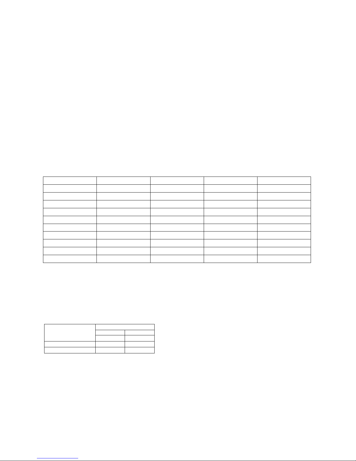
Adaption to various types of gas Table No. 1
Burners Gas type Pressure (kPa) Injector (mm) Mj/hr
Small Natural
1.00
0.90 3.85
Small U-LPG 2.75 0.54 3.75
Medium Natural 1.00 1.18 7.12
Medium U-LPG 2.75 0.70 6.20
Large Natural 1.00 1.55 12.0
Large U-LPG 2.75 0.92 11.25
Wok Natural 1.00 1.55 12.5
Wok U-LPG 2.75 0.95 13.1
Oven Natural 1.00 1.50
10.8
Oven U-LPG 2.75 0.85
9.4
BURNER ADJUSTMENT
1)Primary air adjustment:
Oven burner adjustment: follow the instructions below to adjust the primary air for the over burner:
1) Remove the oven bottom.
2) Loosen the screw P and adjust the position X of the Venturi cone (Fig. 16) according to the measurements indicated in
table 2.
TABLE N°2: Burner primary air regulation (indicative)
BURNER
Type of gas Oven (mm)
M6
Natural fully open
Universal LPG fully open
2) Burner "MINIMUM" adjustment:
Work surface burner adjustment: follow the instructions below to adjust the work surface burner minimum:
1) Light the burner and set the knob to the MINIMUM position (small flame).
2) Remove the knob of the valve that is press fit on the rod of that valve.
3) If the cooker is not equipped with safety valves on the surface burners, insert a sm all slotted scre wdriver into the hole
on the valve rod (Fig. 18) and turn the choke screw to the right or left u ntil t he burner flam e is a djusted to minimum. If th e
cooker is equipped with safety valves, the choke valve is not located in the rod hole, but on the valve body (see fig. 19).
4) Make sure that the flame does not go out when switching quickly from the MAXIMUM to the MINIMUM position.
Oven burner adjustment: follow the instructions below to adjust the minimum:
1) Light the burner setting the knob to the MAXIMUM position.
2) Close the oven door and operate the oven for at least 10 minutes.
3) Set the knob to the MINIMUM position (corresponding to 120°) and then remove it.
Page 6
6
4) With a slotted screwdriver turn the choking screw (see figure 20) and, while observing the flame at the same time
through the cooker porthole, evaluate the consistency of the flame so it remains on when switching quickl y from the
MINIMUM to the MAXIMUM position.
WARNING: The above-mentioned adjustment should be made only with Natural gas burners, while for those
operating with Universal LPG the screw must be locked at the end in a clockwise direction
APPLIANCE ELECTRIC CONNECTION:
The electric connection must comply with the current legal standards an d regulations.
Before making the connection, check that:
- The system electrical rating and the current outlets are adequate for the maximum power output of the appliance (se e
the label applied to the bottom of the casing).
- The outlet or the system is equipped with an efficient gr ound c onnection in accorda nce with the curren t legal standards
and regulations. The company will not be responsible for the non-compliance with these instructions.
When the connection to the power supply network is made using an outlet:
- If the power cord is supplied without a plug, ap ply a standard plug that is suitable for the load indicated on the label.
Connect the wires according to the diagram shown in FIG.21 and check that:
letter L (phase) = brown wire;
letter N (neutral) = blue wire;
ground symbol = green-yellow wire;
- The power cord must be positioned so that an overtemperature of 75 K will not be reached at any point.
- Do not use reductions, adapters or splitters since they might cause false contacts and lead to dangerous overheating.
When the connection is made directly to the electric network:
- Use a device that ensures disconnection from the mains in which the contacts are o pened to a distance that permits
complete disconnection according to the conditions for over-voltage category III.
- Remember that the ground wire must not be interrupted by the circuit-breaker.
- As an alternative, the electric connection can also be protected by a high-sensitivity residual current circ uit-breaker.
- It is highly recommended to attach the special green-yellow ground wire to an efficient g round system.
WARNING: If the power cord is replaced, the ground wire (yellow-green) connected to the terminal, should be
longer than the other wires by about 2 cm.
WARNING: If the supply cord is damaged, it must be replaced by the manufacturer or its service agent or a
similarly qualified person in order to avoid a hazard.
For New Zealand - This cooking range must be connected to the supply by a supply cord fitted with an appropriately
rated plug that is compatible with the socket-outlet fitted to the final sub-circuit in the fixed wiring that is intended to
supply this cooking range.
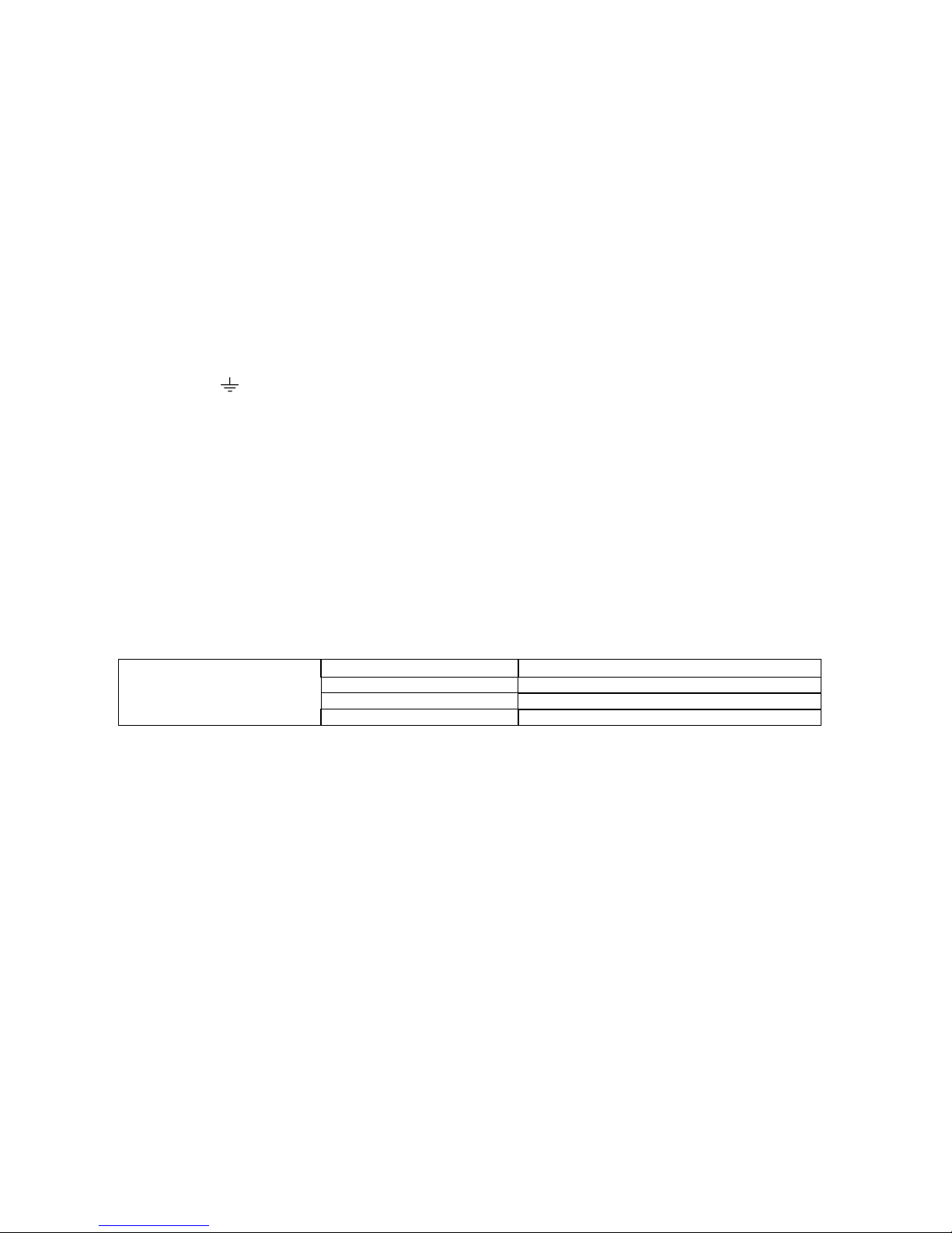
TABLE N°3 : TYPES OF POWER CORDS
Work surface operation Oven operation Cross section 230V ~
Only gas burner Gas oven / Electric grill 3x1mm²
Ventilated Electric Oven 3x1,5mm²
BEFORE LEAVING
When the installation is complete, always check for gas leaks using a soapy solution. Never use a flame to make this
check.
Ignite all burners on high flame to ensure correct operation of gas valves, burners and ignition. Turn gas taps to low
flame position and observe each burner to ensure they ignite completely at all ports and that the flame is stable. Conduct
these checks for each burner individually and concurrently.
When satisfied with the appliance, please instruct the user on the correct method of operation. In case the appliance fails
to operate correctly after all checks have been carried out, please call the Bertazzoni Service Center.
APPLIANCE MAINTENANCE
ATTENTION: IMPORTANT WARNINGS
For cookers resting on a base
ATTENTION: If the cooker rests on a base, take the measures necessary to prevent the cooker from sliding along the
support base.
For cookers with glass covers
ATTENTION: Before opening the appliance’s glass cover, carefully remove all liquid residues from the top of it.
ATTENTION: Before closing the appliance’s glass cover, make sure that the work surface has cooled.
For cookers with electric ovens
During use, the appliance becomes hot. Care should be taken to avoid touching heating elements inside the oven.
For cookers with electric ovens
WARNING: Accessible parts may become hot during use. To avoid burns, young children should b e kept away.
For the food warmer compartment (or drop leaf in our case)
ATTENTION: The internal parts of the food warmer can become hot during use.
Page 7

7
For glass doors
Do not use harsh abrasive cleaners or sharp metal scrapers to clean the oven door gla ss since they can scratch the
surface, which may result in shattering of the glass.
Do not use steam cleaners to clean the appliance.
NOTE: various parts of the cooker heat up reaching temperatures which seem very high but which are actually fully
within safety limits. According to these limits:
1) With the oven on at 200°C for 1 hour, front accessible parts which cannot be grasped, can reach the following
temperatures:
- Control panel: Tmax = Room Temperature +60°C
- Glass of the oven door: Tmax = Room temperature+60°C
- Metal part of the oven door: Tmax = Room temperature+45°C
2) With the oven on at 230°C for 1 hour, the parts which can be grasped, can reach the following temperatures:
- Plastic knobs: Tmax = Room temperature+60°C
- Metal oven door handle: Tmax = Room temperature+35°C
where the room temperature is the temperature in °C of the place where the appliance is installed.
REPLACING PARTS
Before performing any maintenance operation, disconnect the appliance from the gas supply and electricity
network.
To replace parts such as knobs and burners, just remove them from the seats without disassembling any part of the
cooker.
To replace parts such as nozzle supports, valves and electric component s follow the procedure described in the burner
adjustment paragraph. To replace the valve or the gas thermostat, it is also necessary to disassem ble the two rear gas
train brackets, loosening the 4 screws (2 per bracket) that attach it to the rest of the cooker and, unscre w the nuts that
attach the front burner valves to the control support, after removing all the knobs. To replace the gas or electric
thermostat, also disassemble the rear cooker guard, loosening the relative scre ws, to be able to pull out and reposition
the thermostat bulb.
To replace the oven bulb, just unscrew the protection cap that projects out inside the oven. (Fig.22)
WARNING: Ensure the appliance is switched off before replacing the lamp to avoid the possibility of electric
shock.
WARNING: The power cord supplied with the appliance is con nected to that appliance with a type Y connection (in
compliance with standards EN 60335-1, EN 60335- 2-6 and subsequent amendments) for which it must be replaced by
the manufacturer or its service agent or a similarly qualified person in order to avoid a hazard.
If the power cord becomes worn or damaged, replace it based on the information reported in table 3 .
WARNING: If the power cord is replaced, the installer shall ensure that the ground cable is longer than the
phase cables and also shall comply with the warnings regarding the electric connection.
To replace the power cable, lift the terminal board’s cover and replace the cable.
USE AND MAINTENANCE MANUAL
WARNING: This appliance is not intended for use by persons (including children) with reduced physical,
sensory or mental capabilities, or lack of experience and knowledge, unless they have been given supervision
or instruction concerning use of the appliance by a person responsible for their safety.
WARNING: Children should be supervised to ensure that they do not play with the appliance.
DO NOT USE OR STORE FLAMMABLE MATERIALS IN THE APPLIANCE STORAGE DRAWER OR NEAR THIS
APPLIANCE.
DO NOT SPRAY AEROSOLS IN THE VICINITY OF THIS APPLIANCE WHILE IT IS IN OPERATION.
DO NOT STORE OR USE FLAMMABLE LIQUIDS OR ITEMS IN THE VICINITY OF THIS APPLIANCE.
WHERE THIS APPLIANCE IS INSTALLED IN MARINE CRAFT OR IN CARAVANS, IT SHALL NOT
BE USED AS A
SPACE HEATER.
WARNING: SERVICING SHOULD BE CARRIED OUT ONLY BY AUTHORISED PERSONNEL.
DO NOT MODIFY THIS APPLIANCE.
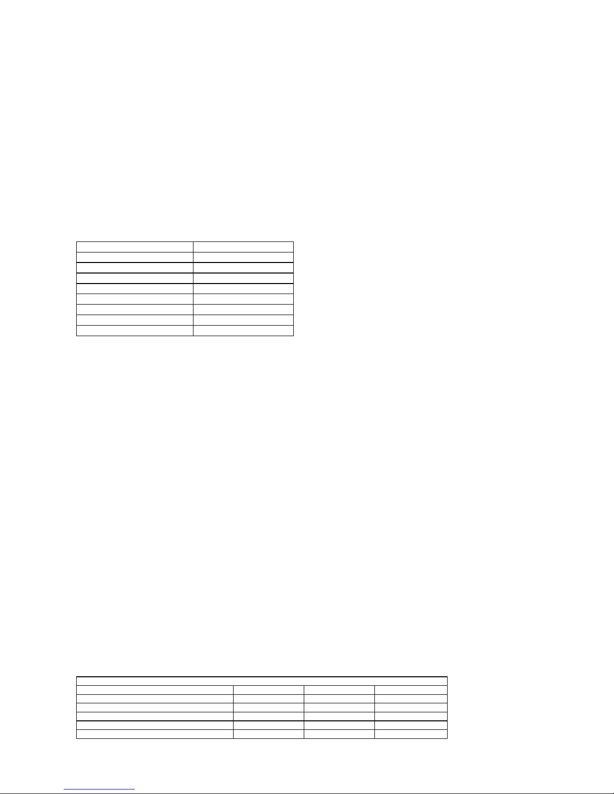
TABLE 4 GAS BURNER DIMENSION
Burner Dimension (mm)
Auxiliary Ø 50
Semi-rapid Ø 70
Rapid Ø 95
Ultra-rapid Ø 130
Page 8
8
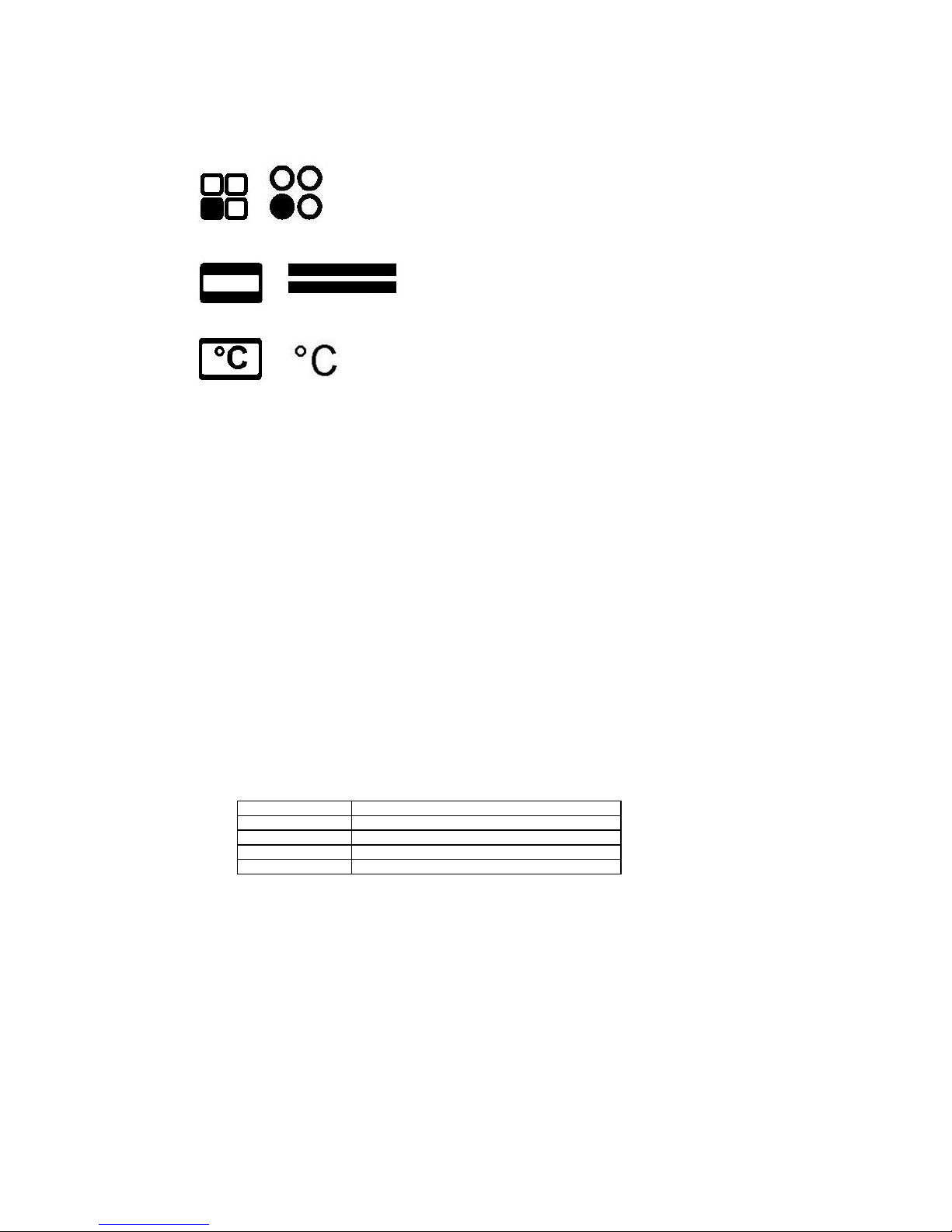
CONTROL PANEL DESCRIPTION
On the control panel, small symbols show the function of each knob or ke y. Here as follows are t he several controls that
a cooker can have:
the symbol o shows the disposition of burners on the worktop, the full dot identifies the burner in
object (in this case the front left burner).
the symbol or shows the running of any oven (gas oven with electric grill, static oven,
9 positions switch)
the symbol or shows the electric thermostat for electric fan oven
USING BURNERS
A diagram is etched on the control panel above each knob which indicates which burner corresponds to that knob. The
burners can be ignited in different ways depending on the type of appliance and its specific characteristics:
- Manual lighting (it is always possible even when the power is cut off): Turn the knob anticlockwise that
corresponds to the burner selected, setting it to the MAXIMUM position at the etched star (large flame Fig.23-24) and
place a lit match up to the burner.
- Electric ignition: Turn the knob counterclockwise that corresponds to the burner sele cted, setting it to the MAXIMUM
position (large flame Fig. 23-24) and keep on pressing the knob in correspondence of the ignition s ymbol marked with a
star (for cookers equipped with ignition trough knob) or press the ignition button marked with a star and release it as
soon as the burner has ignited.
- Burner ignition equipped with safety device (thermocouple)(fig.25): Turn the knob anticlockwise that corresponds
to the burner selected, setting it to the MAXIMUM position at t he etche d s tar (large fl ame F ig. 23-24), pr ess the kn ob a nd
activate one of the above-mentioned ignition devices. Once ignited, keep pressing the knob for about 10 seconds to
allow the flame to heat the thermocouple. If the burner goes out after releasing the knob, repeat the entire operation.
Note: It is recommended not to try to ignite a burner if the relative flame cap is not in the correct position.
If the flame does not light after the first attempt, wait 5 minutes for the gas to dissipate before attempting to re-light the
burner.
Tips for using burners correctly:
- Use suitable pots for each burner (see tab. 5 and Fig. 27).
- When the liquid is boiling, turn the knob to the MINIMUM position (small flame Fig. 23-24).
- Always use pots with a cover.
TABLE N°5
BURNER PAN DIAMETER recommended (cm)
Auxiliary 12-14
Semi-rapid 14-26
Rapid 18-26
Double ring 22-26
NOTE: use flat-bottomed pans
NOTE: after cleaning the burners, make sure the caps “A” an d flame spreader heads “B” are positioned properly
as shown in figure 26A and are not positioned as shown in figure 26B.
WARNING: If the power is cut off, the burners can be lit with matches. When cooking foods with oil and fat,
which are very flammable, the user should not leave the appliance unattended. If the appliance is equipped with
a glass cover, such a cover may break when h eated. Turn off all burners before lowering th e cover. Do not use
sprays near the appliance when it is being used. When using the burners, make sure that the handles of the pots
are correctly positioned. Keep children away from the appliance. If equipped with a cover, before being closed,
any food deposits should be cleaned off the built-in surface.
NOTE: The use of a gas cooking appliance produces heat and humidity in the room where it is installed.
Therefore, proper aeration in the room is needed while ensuring that natural ventilation openings remain
unobstructed (Fig.2) and activating the mechanical aeration device/exhaust hood or electric fan (Fig. 3 and Fig.
4). Intensive and continuous use of the appliance m ay require additional aeration, for example by opening a
window, or more efficient aeration by increasing the power of the mechanical exhauster, if installed.
ATTENTION:Usepotswithaflat
bottom
Page 9
9
USING THE GAS OVEN
All the gas oven cookers are equipped with a thermostat a nd safety device to ad just the cooking temperature. T he oven
temperature is set by turning the knob counterclockwise to match the indicator with the temperature selected. The gas
oven can be combined with a gas grill or an electric grill. See the specific pages for use information.
Operating the fan of the oven by means of the appropriate switch situated on the control panel, the circulation of warm air
guarantees a uniform heat distribution. The preheating of the oven can be avoide d. However for delicate baking, it is
preferable to warm the oven before introducing the baking- pan. The baking system with the fan convection changes in
part the various traditional baking notions. When roasting meat it is not necessary to turn the meat an y more and for a
roast on the spit, it is not indispensable to use the spit-roaster,
but is sufficient to put the meat directly on the grate.
With the use of the fan gas oven, the baking temperatures a re slightly lower of ab out 10-15°C compared to those in use
with the traditional gas oven. The oven can also b e used in a traditional way, for foods requiring h eat from the bottom,
e.g. pizza.
WARNING: If the burner flames are extinguished accidentally, turn off the control knob and do not try to relight
the oven until after at least 1 minute.
ABLE N°6
THERMOSTAT SETTING TEMPERATURE °C
1 120
2 140
3 160
4 175
5 190
6 210
7 235
8 250
The oven burner can be ignited in different ways:
- Manual lighting (it is always possible even when the power is cut off):
To light the oven, open the oven door and t urn the knob so the no. 8 on the scale matches the i ndicator (fig.28-29). At
the same time put a lit match next to the ignition tube that is visible on th e oven level (fig. 30). Then press the therm ostat
knob (this makes the gas start to flow) and keep it pressed, after the burner h as been completely lit, for 10 seconds.
Release the knob and make sure that the burner remains on, otherwise repeat the operation.
- Electric ignition (only for the models equipped with this device):
In this case, first open the oven door, then turn the knob to the maximum temperature setting (number 8). Then press the
thermostat knob (models with ignition trough knob). Wait about 10 seconds after the burner h as been completely lit and
then release the knob. Make sure that the burner remains on, otherwise repeat the operation. As for cookers without
ignition trough knob, press the thermostat knob and the key with the spark symbol, wait about 10 seconds after the
burner has been completely lit and then release the knob. Make sure that the burner remains on, other wise repeat the
operation.
The ignition device should not be used for more than 15 seconds. If after that period the burner still has not
been lit, do not use the device and open the door of the room or wait at least 60 seconds before trying to light
the oven again.
WARNING: when trying to light the oven, the door must always be open. When using the oven, leave the cooker
cover open to prevent it from overheating.
NOTICE: when using the oven for the first time it should be operated for 15-30 minutes at a temperature of
about 250° without cooking anything inside in order to eliminate any moisture and odours from the internal
insulation.
During normal oven use, after lighting the burner and setting the desir ed temperature, wait about 15 minutes before
putting in any food to preheat the oven.
The oven is equipped with 5 guides at different heights level (fig.31a) which can be use d to insert shelve s or the tray. To
keep the oven as clean as possible it is recommended to cook meat on the tray or on the shelf that has been inserted
inside the tray. The table below lists the general cooking times an d the position of the tray for different types of foods.
Personal experience will help to determine any variations in the values reported in the table. In any case, it is
recommended to follow the instructions of the specific recipe being used.
Temperatures between brackets are referred to the use of oven with fan assisted gas.
TABLE N°7
GAS OVEN COOKING TABLE
TEMP °C HEIGHT MINUTES
MEAT
PORK ROAST 220 (210) 4 60-70
BEEF ROAST (YOUNG STEER) 250 (240) 4 50 -60
BEEF ROAST 240 (230) 4 60-70
VEAL ROAST 220 (210) 4 60-70
Page 10

10
LAMB ROAST 220 (210) 4 45-55
ROAST BEEF 230 (230) 4 55-65
ROAST HARE 235 (225) 4 40-50
ROAST RABBIT 220 (210) 4 50-60
ROAST TURKEY 235 (225) 4 50-60
ROAST GOOSE 225 (215) 4 60-70
ROAST DUCK 235 (225) 4 45-60
ROAST CHICKEN 235 (225) 4 40-45
FISH
200-225 (190-215) 3 15-25
PASTRY
FRUIT PIE 200 (210) 3 35-40
TEA CAKE 190 (180) 3 50-55
BRIOCHES 175 (165) 3 25-30
SPONGE CAKE 235 (225) 3 20
RING CAKE 190 (180) 3 30-40
SWEET PUFF PASTRIES 220 (210) 3 20
RAISIN LOAF 220 (210) 3 15-20
STRUDEL 180 (170) 3 15-20
SAVOIA COOKIES 190 (180) 3 15
APPLE FRITTERS 220 (210) 3 20
SAZOIARDI SANDWICH 220 (210) 3 20-30
TOAST SANDWICH 250 (240) 4 5
BREAD 220 (210) 3 30
PIZZA 220 (210) 3 20
USING THE 2+0 CHANGE-OVER SWITCH (figure 35-36)
(only for gas ovens)
The 2+0 change-over switch used for gas oven models.
the symbol or is for oven fan and light operation, to use the gas oven or grill with fan.
the symbol or is for turning on the oven light
USING THE ELECTRIC THERMOSTAT FOR MULTI-FUNCTION COOKERS
The thermostat provided in every model keeps the temperature inside the ov en constant at a temperature range from
50°C to 250°C .
Turn the knob clockwise (Figure 34-35),to align the selected temper ature on the metal ring with the indicator pr inted on
the front panel. An orange light shows the thermostat is working and goes off when the oven temperature has exceede d
the selected temperature by 10°C and comes on when the selected temperatures dro ps below 10°C. The thermostat
can operate the oven heating elements only if the switch is in one of the heating el ement operating m odes. If the switch
is set to 0, the thermostat will not operate the heating elements.
USING THE 9-SETTING MULTI-FUNCTION OVEN SELECTOR
The 9+0 setting change-over switch for multi-function ovens is used to control, along with the thermostat, the fan motor
and heating elements. To turn on the elements, both the knob on the 9+0 switch and thermostat nee d to be turned; if
only one knob is turned, the oven will not work and onl y the light or fan motor will come on. The electric oven has 4
heating elements: a bottom element, two top elements and a round element; turn the change-over switch knob (Figur e
36-37) to enable the heating element matching the symbol on the metal ring. However to operate this element, you nee d
to turn the thermostat knob until the orange light shows the element has come on. If you position the change-over switch
to any one of the nine operating modes, the relative he ating element is enabled as well as the oven light. After the
temperature and heating elements to operate have been selected, the oven heating elements are operated by the
thermostat, so it is normal for the orange light to come on and off during operation.
To turn off the electric oven, set the change-over switch knob to 0 to prevent the thermostat operating the heating
elements. The heating elements will be disa bled, but the fan motor and oven light can be turned on from the ch angeover switch.
The switch has 9 settings, for 9 different types of oven operation:
- the symbol
or indicates that only the oven light is on;
Page 11

11
- the symbol or indicates that the 1300W bottom heating element and external 900W top heating
element are on;
- the symbol
or indicates that only the external 900 W top heating element is on;
- the symbol
or indicates that only the 1300W bottom heating element is on;
- the symbol
or indicates that only the 2000 grill heating element is on (see specific section);
- the symbol or indicates that the external 900W top he ating element and 2000W grill heating element
are on (see specific section);
- the symbol
or indicates that the e xternal 900W top heating element, the 2000W grill heating element
and fan motor are on (see specific section);
- the symbol
or indicates that the 2400W round heating element and fan motor are on;
- the symbol
or indicates that only the fan motor is on.
When the knob is turned to one of these nine positions, the oven light is always on, to indicate tension inside the oven.
USING THE ELECTRIC OVEN WITH NATURAL CONVECTION
When using the oven for the first time, leave it on for maximu m 30 minutes at a temperature of 250°, t o eliminate smell
from the internal seals.
During normal use, select the cooking temperature using the thermostat knob, then wait for the orange lig ht to go off
before putting foods in.
The oven has 5 grooves at different heights (Figure 31a) for fitting racks or trays. To prevent getting the oven to o dirty,
meat should be cooked on a tray or rack placed in the tray.
TABLE 8 COOKING TIMES FOR ELECTRIC OVENS WITH NATURAL CONVECTION
TEMP °C HEIGHT MINUTES
MEAT
ROAST PORK 225 3/4 60-80
ROAST STEER 225 3/4 60-80
ROAST OX 250 3/4 50-60
ROAST VEAL 225 3/4 60-80
ROAST LAMB 225 3 40-50
ROAST BEEF 230 3/4 50-60
ROAST HARE 250 3/4 40-50
ROAST RABBIT 250 3 60-80
ROAST TURKEY 250 3 50-60
ROAST GOOSE 225 3 60-70
ROAST DUCK 250 3/4 45-60
ROAST CHICKEN 250 3/4 40-45
FISH
200-225 2 15-25
CAKES AND PASTRIES
FRUIT CAKE 225 2 35-40
SANDWICH CAKE 175-200 2 50-55
BRIOCHES 175-200 2 25-30
SPONGE CAKE 220-250 2 20-30
DOUGHNUTS 180-200 2 30-40
PUFF PASTRY 200-220 2 15-20
GRAPE TART 250 2 25-35
STRUDEL 180 2 20-30
SAVOYARD BISCUITS 180-20 0 2 40-50
APPLE FRITTERS 200-220 2 15-20
PUDDING WITH SAVOYARD
BISCUITS 200-220 2 20-30
TOASTED SANDWICH 250 3 5
BREAD 220 3 30
PIZZA 220 2 20
Page 12

12
USING THE ELECTRIC OVEN WITH FAN
When using the oven for the first time, leave it on for maximu m 30 minutes at a temperature of 250°, t o eliminate smell
from the internal seals.
Before cooking foods, make sure the oven reaches the selected temperature and the orange light is off. This type of
oven has a round heating element inside, where the fan for forced air circulation in a horizontal direction is positioned.
Based on this operating principle, a fan oven can be used for different kinds of cooking at the same time, without
changing the taste of the food. A few models are fitted at the r ear with a r emovable metal filt er that retains grease when
cooking roasts. This filter should be cleaned regularly with soapy water to remove the gr ease and ri nsed thor oughly. T o
remove the metal filter, apply gentle pressure upwards on the tab, indicated by the arrow. The circulation of hot air
ensures that heat is evenly distributed. It is not necessary to preheat the oven, however in the case of delicate baking,
the oven should be preheated before putting in baking trays. The convectio n fan cooki ng system chang es to some exten t
concepts about traditional cooking. Meat does not have to be turned during cooking an d a spit does not have to be used
for rotisserie roasting. The meat can be simply put on the rack.
TABLE 9
COOKING TIMES FOR ELECTRIC FAN OVENS
TEMP °C HEIGHT MINUTES
MEAT
ROAST PORK 160-170 2 70-100
ROAST STEER 170-180 2 65-90
ROAST OX 170-190 2 40-60
ROAST VEAL 160-180 2 65-90
ROAST LAMB 140-160 2 100-130
ROAST BEEF 180-190 2 40-45
ROAST HARE 170-180 2 30-50
ROAST RABBIT 160-170 3 80-100
ROAST TURKEY 160-170 3 160-240
ROAST GOOSE 160-180 3 120-160
ROAST DUCK 170-180 2 100-160
ROAST CHICKEN 180 2 70-90
FISH
160-180 2-3
CAKES AND PASTRIES
FRUIT CAKE 180-200 2 40-50
SANDWICH CAKE 200-220 2 40-45
BRIOCHES 170-180 2 40-60
SPONGE CAKE 200-230 2 25-35
DOUGHNUTS 160-180 2 35-45
PUFF PASTRY 180-200 2 20-30
GRAPE TART 230-250 2 30-40
STRUDEL 160 2 25-35
SAVOYARD BISCUITS 150-18 0 2 50-60
APPLE FRITTERS 180-200 2 18-25
PUDDING WITH SAVOYARD
BISCUITS 170-180 2 30-40
TOASTED SANDWICH 230-250 3 7
BREAD 200-220 3 40
PIZZA 200-220 2 20
POSITIONING THE OVEN TRAYS & SHELVES
The Grill Tray or Oven Shelf can be located in any of the four height positions in the oven (See Fig. 31a).
Refer to the ‘Oven Cooking Tables’ for the recommended shelf position. When fitting the trays or shelves, ensure they
are fitted between the two wires that are closest together (See Fig. 31b).
Oven Shelves have a stop so that they are not fully withdrawn by accident. To fully remove the Oven Shelves, lift the
front of the shelf slightly and withdraw fully from the oven. (See Fig. 31d) Note that the Grill Tray does not have a stop
position and can be fully withdrawn without interruption, so be careful not to accidentally fully withdraw the tray.
To remove the Oven Shelf Support, remove the top and bottom screws shown in Fig 31c and then pull the support from
the holes in the rear oven wall. Repeat for opposite side. Replace in reverse procedure.
Page 13

13
USING THE STATIC ELECTRIC GRILL
The electric grill can be combined with the gas or electric oven.
With a gas oven + electric grill combination, the grill is operated from the oven thermostat knob.
The electric grill for gas oven cookers has a 2500W rating.
IMPORTANT: When using the electric grill in electric oven cookers, do not turn the thermostat knob to more
than 150°C to prevent overheating the oven front; the oven has been designed for closed-door grilling.
Grilling on the rack: In this case, the rack should be put at level 1 or 2, placing foods on top of the rack and a drip tra y
below. Turn on the grill heating element, setting the thermostat to the relative position.
IMPORTANT NOTE: the oven door must be kept closed when grilling using the static electric grill.
WARNING: during use the appliance gets very hot. Do not touch the heating elements inside the oven.
WARNING: Accessible parts may become hot when the grill is in use. Children should be kept away.
USING THE ELECTRIC GRILL WITH FAN
The electric grill with fan is a special function for optimal grilli ng, with the oven rack at an intermediate position and the
drip tray below.
With gas oven cookers with electric grills, set the thermostat to the grill symbol and the 2+0 change-over switch to the
position to turn on the 1500W grill heating element and fan motor.
With cookers with a 9-setting change-over switch, set the 9+ 0 switch to the relative position and the electric thermostat to
the temperature required, to turn on the grill heating element and fan motor.
IMPORTANT: When using the electric grill with fan, do not turn the thermostat knob to not more than 175°C
(between 150° and 200°C) to prevent overheating the oven front; the oven has been designed for closed-door fan
grilling.
USING THE THERMOMETER Figure 40
The cooker is fitted with a device to measure the temperature in the middle of the oven.
This lets you check the temperature inside the oven and adjust food cooking temperatures more accurately.
ELECTRIC OVEN
When you turn on the oven, the orange light comes on to indicate that the heating elements are working: The
thermometer dial will start to move towards the set temperature.
The orange light will keeping coming on and off, indicating that the heating elements are working to maintain the
temperature inside the oven.
The light may go off for a few minutes before the thermometer has reached the temperature required. This is normal,
because operation of the heating elements is regulated so that heat is distributed properly inside the oven.
Heat is optimally distributed inside the oven when the thermometer dial has stopped.
If the oven temperature drops or goes up, the thermometer dial will follow these variations in the same way.
When the oven is turned off, the temperature on the thermometer will slowly drop until it reaches room temperature.
NOTE: The temperatures on the knob are indicative. Follow the thermometer temperature for cooking.
GAS OVEN
When the oven is turned on, the burner will start working at the maximum and the thermometer dial will start to move
towards the set temperature.
The flame may die down before the thermometer has reac hed the temperature required. T his is because burner power
is reduced so that heat can be evenly distributed inside the oven.
Heat is optimally distributed inside the oven when the thermometer dial has stopped.
When the oven is turned off, the temperature on the thermometer will slowly drop until it reaches room temperature.
NOTE: The Thermostat Position and Oven Temperature correspondence in table no. 6 is indicative and depends on
various factors such as the type of gas and supply pressure.
Follow the thermometer temperature for cooking.
NOTE: it is normal to record different temperatures from those indicated on the panel thermometer, when you measur e
the temperature in the middle of the oven using a different thermometer.
The temperature indicated by the thermometer is the mean temperature inside the oven and does not indicate the
temperature of any single point.
3 KEYS ELECTRONIC PROGRAMMER (fig.43)
The first start up
The numbers and the A letter on the display are blinking w hen the oven is switched on for the first time, or
after a power cut:
the appliance cannot be operated in this condition.
To set the hour and/or to enable the appliance to operate press the M key for at least 2 seconds: the A letter
turns off and the numbers now are steady on the display.
The dot (3) starts blinking: press the - or
+
key to set the hour.
The hour is accepted by the programm er just few se co nd after havin g releas ed th e ke y.
N.B. the appliance can be c or rect l y us e d f or coking only when you will see on t h e dis pl ay t he symbol (2).
Page 14

14
The symbols on the display:
1
A
*
Automatic programme is working.
(* in some models there is the writinq 'Auto' instead of A).
2
The appliance is ready for manual use (not automatic).
3
•
When blinking, the programmer is in setting hour mode.
4
Timer set.
5 -
Decreasing numbers when setting the timer.
Also for choose your desired sound level ( 3 levels available).
6
M
"Mode" kev to access the programming option s of the pro gram m e.
7
+
Increasing numbers when setting the timer.
Timer
The purpose of the timer is just of a sound signal, which can be set for a max time of 23h59min. once elapsed
the set time, the (4) symbol turns off and a sound signal is heard; this sound set off automatically in 7min, or
you can stop it by pressing any key of the program mer. To set the timer press the M key for 2 seconds, or
anyway just to see the (4) symbol blinking. Set the timer by using the
+
or - keys. Release the + or - key when
you have matched your desired time. In a few seconds the current time appears on the display together with
the ) symbol. The countd ow n starts immediately from now on.
Semi-automatic cooking
Cooking time: Once having selected a coking function and set the desired temperature, press the M key for a 2
seconds time to access the programming mode. The (4) symbol appears. Release and press again the M key.
On the display, the A symbol starts blinking and the " dur " writing appears on the display, then it changes to O'
00. Set the cooking time with the - or
+
keys. (max available tim e: 10h). The selected time is automatically
processed by the programmer in a few seconds, or you can also touch the M key many times just to see again
the current time.
The A and (2) symbols will be on the display. Once the set cooking time is finished, a sound will be heard and
the oven automatically switches off. Please see the following paragraphs about how to disable the sound alarm
and restarting the oven.
End of cooking
once having selected a cooking function and set the desired temperature, touch the M key to access the
programming mode for at least 2 sec. the ) sy m b ol switches on. Release and touch again the M key.
On the display the A symbol starts blinking and the writing "dur" appears. Touch again the M key. On the
display the writing "End" appears. The last one changes few seconds after with the symbol 0· 00.
Set the end of cooking time with the keys - or
+.
(maximum available time: 10hOOm).
The selected time is automatically processed by the programmer in a few seconds, or you can also touch the
M key many times just to see again the current time.
The cooking immediately starts, while on the program mer display the current time is shown again in a few
seconds. The A and (2) symbols will be on the display.
Once the set end of cooking time is finished, a sound will be heard and the oven automatically switches off.
Please see the following paragraphs about how to disable the sound alarm and restarting the oven.
Automatic cooking
Set a cooking time following the instructions on the cooking time paragraph, then set the end of cooking time
following the instructions on the previous paragraph. (Max available end of cooking time 24h). The oven
automatically switches on at a determined time which is the difference between the end of cooking time and
the cooking time.
During the waiting time before cooking, which goes from the oven start to the heating, on the display appears
the A symbol to show that an automatic program is on and the current time. The oven on is marked by the (2)
symbol. Once the set end of cooking time is finished, a sound will be heard and the oven automatically
switches off.
Please see the following paragraphs about how to disable the alarm and restarting the oven.
How to disable the sound alarm:
To disable the sound just touch one of the keys.
Operating again the
oven
Once a semi-automatic or automatic cooking has expired, on the display appear the current time and the
blinking A symbol. In this condition, the heating elements and the light bulb of the oven are disabled. To enable
again the oven, just touch and keep the M key up to see the sy mbol (2) on the display and the A symbol
disappears.
OTHER FUNCTIONS
How to delete a cooking time
(semi-automatic or Automatic)
Page 15

15
To delete a semi-automatic or automatic cooking program, with the A symbol on, touch together the - and
+
keys for at least 2 seconds or anyway up to see the (2) and the disabling of A symbol.
How to delete the countdown timer
To delete the counting of the timer, which symbol is ) t touch the M key for at least 2 seconds or anyway up to
see the ) symbol blinking. Touch together the - and
+
keys.
Checking the function settings
The set or remaining time of every cooking function of the programmer can be recalled to the display by
entering in program mode with the M key. Touch and keep the M key for almost 2 seconds or anyway up to
see the (4) symbol. The remaining time appears on the display, or a series of zero numbers if the timer is
disabled. Touch again the M key. On the display appears the "dur" writing, then alternately the remaining time
or a series of zero number (disable timer).
By touching again the M key, the end of cooking time appears together with the "End" writing.
How to change the current time or the sound level
With the programmer in standard mode, the (2) symbol is on, touch together the - and + keys for at least 2
seconds or anyway up to see the dot (3) blinking.
To update the hour on the display:
touch the + or - keys.
To change the sound level:
touch the M key. On the display appears the writing: Ton.. followed by a number.
Select with the - key your favourite sound level.
Note: number 1 is referred to the highest sound level. The available levels are 3.
Attention:
Power cut causes the loss of any program, even the clock; that means the programmer will have to
be set again
.
3 KEYS ELECTRONIC CLOCK (FIG. 43)
Mains frequency detection
At power on mains frequency is determined. When the timer is connected to 60Hz, the Celsius symbol is
flashing during start-up.
Power On
At power on, the relay contact is opened. The display and AUTO symbol flashes and time of day starts
from 0:00. Power on state with flashing daytime remains until time of day is set.
Setting Time of Day
Press PLUS and MINUS button simultaneously. At Power On, also MODE button is possible.
Time of day can be set with PLUS or MINUS, while the colon between hours and minutes is flashing.
Quick setting mode starts when PLUS or MINUS is held for more than 1 second. If daytime setting mode
is selected while an automatic program is active, the automatic program is cancelled.
The Buzzer
The buzzer interval alarm signal sounds if minute minder has reached the end time. The signal can be
switched off by pressing any key or by passing the signal duration limit.
Changing the Buzzer frequency
First press Plus and Minus simultaneously (menu far editing the time) and then Mode for selecting the
menu far changing the buzzer frequency. While the text tonX is visible the buzzer signal frequency can
be changed by touching Minus repetitively.
Note: If the touch pad is inactive, a visual alarm will only be reset when a valid key combination is
pressed far more than 2 seconds.
Clearing Programs and Manual function
The duration of the minute minder can be cleared by
a) "clear Function": First select minute minder program, then press PLUS and MINUS button
simultaneously.
after this clear the display returns from adjustment mode to time of day immediately.
b) Back counting of duration to zero. The timer remains in adjustment mode.
Minute Minder
While minute minder mode is selected, the Bell symbol flashes and the display reads the remaining time
in hours and minutes, only if the last minute is counting down the remaining seconds are displayed.
An active minute minder program is indicated by the statically illuminated Bell symbol. If alarm time has
finished, an acoustic interval signal sounds and the Bell symbol flashes.
Page 16

16
The minute minder program runs independently of other programs.
Key Lock
After power on reset or when no key is pressed for
7
seconds, the key look function is activated. Pressing a
valid key or key combination for 2 seconds or more will deactivate the key lock.
USING THE SELF-CLEANING OVEN
On models which have this device, the self-cleaning oven differs from normal ovens because the inner surfaces are
coated with a special micro-porous enamel that absorbs and eliminates grease residues during cooking. If liquid gr ease
is released, self-cleaning is not sufficient, so wipe the grease stains with a damp sponge and then heat the oven to the
maximum temperature, wait for it to cool down and wipe again with a damp sponge.
ABNORMAL OPERATION
Any of the following are considered to be abnormal operation and may require servicing:
• Yellow tipping of the burner flame. • Burners failing to remain alight.
• Sooting up of cooking utensils. • Burners extinguished by cupboard doors.
• Burners not igniting properly. • Gas valves, which are difficult to turn.
In case the appliance fails to operate correctly, contact Bertazzoni Service Center.
CLEANING THE APPLIANCE
Before any cleaning, unplug the appliance and turn off the gas tap.
Do not use steam cleaners to clean the appliance
Cleaning the hob:
Clean the burner heads, enamelled steel pan supports, enamell ed caps and flame spreaders regularly using warm soapy
water. Rinse and dry well.
Use a cloth to wipe away any liquids spilt from pans.
If the gas tap does not open or close easily, do not force it, but seek technical assistance immediately.
Cleaning enamelled parts:
Clean enamelled parts frequently with soapy water, to keep their char acteristics unaltered . Never use abrasive powders.
Do not leave acid or alkaline substances (vinegar, lemon juice, salt, tomato juice, etc.) on enamelled parts, and clean the
parts when still warm.
Cleaning stainless steel parts:
Clean with soapy water then dry with a soft cloth. Use special stainless steel cleaning products re gularly to maintain the
shine. Never use abrasive powders.
Cleaning the flame spreaders:
As the flame spreaders rest on the hob surface, to clean them, remove and wash with soapy water. Dry well and make
sure the holes are not obstructed, before putting them back in position.
Cleaning the oven glass panel:
The oven glass panel can be removed. After o pening the doors and blocking the hinges (figure 41) remove the glass
panel (figure 42) and clean. Clean the panel when the oven is cold, using a damp cloth. Do not use a brasive products.
Put the glass panel back, making sure the smooth part is on the outside and the pri nted part inside t he oven door. Then
release the hinges.
Note: do not release the hinges if the glass panel is not fitted on the door.
Cleaning inside the oven:
To make heavy-duty cleaning easier, the door can be removed as follows. After opening the door and blocking the
hinges (figure 41), put the door in a semi-open position a nd pull towards yourselves until it is rele ased. To reassemble,
proceed as above in reverse. The side racks can also be removed, by removing the nuts securing them to the oven.
Cast iron or aluminium strip racks:
Soft aluminium-bottomed pans are not recommended, to prevent leaving permanent marks on the rack surface which
cannot be removed with normal washing.
Page 17

17
Fig. 1
Fig. 2 Fig. 3 Fig. 4
Fig. 5
Page 18

18
Fig. 6
Page 19

19
Fig. 7
Page 20

20
Fig. 8
Page 21

21
Fig. 9
Page 22

22
Fig.10 fig.11 fig.12 fig13
fig14 fig15 Fig. 16
Fig. 17 Fig. 18 Fig.19
T
Fig.20 fig.21 Fig.22
Page 23

23
Fig.23 Fig.24 fig.25
fig.26 fig.27
fig.28 fig.29 fig.30
Page 24

24
fig.31a
Fig.31b
Fig.31c Fig.31d
Fig. 32 Fig. 33
Page 25

25
Fig. 34 Fig. 35 Fig. 36
Fig. 37 Fig. 38 Fig. 39
Fig. 40 Fig. 41 Fig.42
Fig. 43
Page 26

26
AFTER-SALES TECHNICAL SERVICE AND SPARE PARTS
Before leaving the factory, this appliance was tested a nd adjusted by specialist skilled staff to give the best operating
results. Any subsequent necessary repairs or adjustments must be carried out with the greatest care and attention by
authorised personnel. For this reason, we strongly adv ise you contact the Bertazzoni Service Center, specifying the
nature of the problem, the model of the equipment and the serial number. This data is provided o n the data label adhered
to the base of the appliance and on the duplicate data label. Always use original Bertazzoni spare parts.
OVERALL DIMENSIONS
AM64C61BX
Page 27

27
TU64C61BX
BERTAZZONI GROUP ABN 38 069 686 326
650 Bridge Road, Richmond, Victoria 3121
Service & Spare Parts: 1300 748 308
Bertazzoni After Sales Service - P.O. Box 543 SOMERTON VIC 3061
Email: customercare@bertazzonigroup.com.au
Page 28

28
Cod. 310793
 Loading...