


The High Voltage Peopl e
AND OPERATING
INSTALLATION
MANUAL
BERTAN SERIES 205B

WARRANTY
The Del Power Conversion Group ("Del") warranties each of its products to be of sound design and
free from defects in material and workmanship. Our obligation under this warranty is to repair or
replace (at our option) FOB our factory:
Any STANDARD or CUSTOM product, or part thereof, at no charge, within 1 year after shipment
date, which proves defective under normal use.
To exercise this warranty, contact the Customer Service Depart ment at t he factory
(outside the U.S.A., contact your local Del sales representative) to obtain a
Returned Material Authorization (RMA) number and shipping instructions. Send the
product, shipping prepaid, to Del's factory. Repairs will be made and the product
returned - we will cover return shipping charges. All repairs are shipped UPS Ground.
Upon request, we can utilize faster shipp ing methods at customer’s expense. Repaired
products are warranted for the balance of the original warranty period or at least 90 days.
Replaced products will have a new 1-year warranty beginning the day unit is shipped
back to customer.
LIMITATION OF WARRANTY
Del does not warrant that the products can be used for any particular purpose other
than those covered by the applicable specifications. This warranty does not apply to
defects resulting from product modification without Del's express written consent
or misuse of any product or part. Del assumes no liability, in any event, for
consequential damages, for anticipated or lost profits, incidental damages or loss of time
or other losses incurred by purchaser or any third party in connection with products
covered by this warranty.
Installation and Operating Manual –Series 205B Page 2

TABLE OF CONTENTS
Paragraph Title Page
SECTION 1 - GENERAL INFORMATION 4
1.1 PURPOSE OF THE EQUIPMENT 4
1.2 DESCRIPTION 4
1.3 SPECIFICATIONS 4
1.4 OPTIONS 4
1.5 SAFETY TERMS 4
1.6 WARRANTY INFORMATION 5
SECTION 2 - OPERATION 6
2.1 INSTALLATION 6
2.2 FRONT PANEL CONTROLS AND DISPLAYS 6
2.3 REAR PANEL CONT ROLS, CONNE C T ORS, AND TERMINALS 6
2.4 POLARIT Y REVERSING: 7
2.5 PREPARAT I ON FOR USE 8
2.6 LOCAL OPERATION 8
2.7 REMOTE OPERATION 9
2.8 COMPUTE R PROGRAMMING (Opt i onal) 10
2.9 INPUT POWER 12
2.10 CURRENT LIMITING 12
2.11 HIGH VOLTAGE OUTPUT 12
SECTION 3 - THEORY OF OPERATION 13
3.1 FUNCTIONAL DE SCRIPT I ON 13
3.2 CIRCUIT DESCRIPTION 13
SECTION 4 - MAINTENANCE 14
4.1 GENERAL 14
4.2 CLEANING 14
4.3 CALIB RATION SERVICES 14
SECTION 5 - SPECIFICATIONS 15
Installation and Operating Manual –Series 205B Page 3

SECTION 1 - GENERAL INFORMATION
1.1 PURPOSE OF THE EQUIPMENT
The Series 205B is a family of regulated precision laboratory high voltage power supplies. They
provide exceptional performance in critical applications such as nuclear and electro-optical
instrumentati on, precisi on CRT a nd electron beam applicat ions.
1.2 DESCRIPTION
The Series 205B is a family of 19” rack-mountable power supplies with output voltages up to 50
kV. The units consist of a DC power supply that converts the AC line power to a low DC voltage
and a DC to DC converter that generates the high DC output voltage. Low voltage electronic
solid-state circuitry is mounted on the PCB100, and the high voltage assembly is fully
encapsula t ed for reliable, arc-free, operation.
These stable, low noise high voltage power supplies feature front panel digital voltage and current
metering, and calibrated direct-reading front panel controls. The rear panel features a HV output
connector, a connector for remote analog programming and output voltage and output current
monitoring, the output polarity switch, line power plug, fuse, and AC voltage selection switch.
All u nits ha ve arc a nd short circui t protection for safe, r eliable, and arc-free operat ion. Although
primarily designed for rack mounting, the unit may also be used in benchtop applications.
1.3 SPECIFICATIONS
For the Series 205B detailed specifications, refer to the Specifications section.
1.4 OPTIONS (OEM APPLICATIONS ONLY)
Isolated Floating Output
Units can be provided with the output capable of floating up to ±2kV from ground. All controls,
programming and monitoring functions operate normally, referenced to ground. The high voltage
output polarity, with respect to the floating input terminal is reversible.
1.5 SAFETY TERMS
The
WARNING
death. The
used in this manual explains dangers that could result in personal injury or
CAUTION
used in this manua l explains hazards that could da mage th e i nstrument.
Installation and Operating Manual –Series 205B Page 4

1.6 WARRANTY INFORMATION
The Warranty is given on the inside front cover of this Instruction Manual. If there is a need to
exercise the Warranty, contact the factory to determine the proper action to be taken.
NOTE attempting to repair or tampering with the unit while still under warranty (less than 12
mont hs since the da te of s hipment ) will v oid th e warranty. All in-wa rra nty repairs s hould be sent
to the factory.
Installation and Operating Manual –Series 205B Page 5

2.1 INSTALLATION
SECTION 2 - OPERATION
WARNING!
This unit produces hazardous voltage. Do not apply line voltage input unless
adequate ground is connected to the unit and the high voltage output has been properly
connected.
2.2 FRONT PANEL CONTROLS AND DISPLAYS
Power Switch:
A rocker switch turns the line power on or off to the entire instrument. The display panel will be
lit when line power is applied to the unit.
Output Meter:
The digita l output meter can display the out put cu r rent or the out put voltage. A switc h below t he
meter allows the op erator to sele c t which output parameter to monitor. The accuracy of the meter
is given in the Specification section.
Polarity Indicator:
An LED on the front panel display indicates the polarity of the output. The appropriate LED is lit
as soon as line power is applied regardless of whether high voltage output is enabled or disabled.
To change the polarity setting, see paragraph 2.4.
Voltage Controls:
The output voltage is the sum of the course and fine dial settings as described below.
Fine Adjust: A continuous, 10-turn, locking digital dial directly reads from 0 V to 1kV with a
resolution of 0.2V on all models.
Coarse Adjust: The voltage switch sets the output voltage in increments of 1kV. In addition, a 1
kV selector switch, with up to 10 positions, is provided on all 3kV to 30kV models. A 5 kV
selector switch, with up to 6 positions, is provided on all 20kV.
On 30kV & 50kV model a continuous multi-turn digital dial is used to adjust the high voltage
outp ut. The resolution and repea tabil ity of this cont rol is 2 0 .0V.
2.3 REAR PANEL CONTROLS, CONNECTORS, AND TERMINALS
Gnd:
Ground is connected to the case of the Series 205B.
Output Connector:
The HV output connector mates with a shielded mating connector supplied with each unit. Refer
to the specifications on page 12 to identify the mating connector. Assembly procedures for
mating connectors are given at the end of this manual. Only the proper mating connector should
be used with the indicated power supply and the power supply should NEVER be energized
without a mating connector and suitable load connected.
Installation and Operating Manual –Series 205B Page 6

Fuse:
The fuse is the ac line power fuse. It is rated for 1A, 250Vac for 105Vac-125Vac operation and
0.5A, and 250Vac for 210Vac-250Vac operation. Should a fuse ever need replacement, only
these values should be used unless otherwise advised by a qualified Del service technician.
Line Voltage Selector:
The line voltage selector selects the appropriate line voltage 105Vac-125Vac or 210Vac-250Vac
at 50-60 Hz. By default, power supplies are shipped from the factory in the 105-125V position.
Before energizing your power supply, verify that the line voltage selector switch is in the proper
position for your mains input.
AC Line Plug:
The IEC 320 line plug receptacle accepts a three-wire female line plug for ac line power.
WARNING!
This unit is equipped with a three-wire grounded line cord. This must be used
with a three-w ire receptacle where the "thir d wir e" is connected to ear th ground; other w is e
personal injury or death may occur.
2.4 POLARITY REVERSING:
WARNING!
Before attempting to reverse the power supply’s polarity, the power supply must
be turned off and the output fully discharged. Failure to follow these procedures may result in
damage to the power supply, associated test equipment and/or personnel
.
For 1kV to 5kV output models, a screwdriver-adjustable POLARITY SELECTOR SWITCH is
accessible at the rear panel of the unit, next to the HV output connector. For 10kV to 50kV
output models, the polarity of the HV output is reversible by means of an internal switching
mechanism that is easily accessible upon removal of the top cover. The polarity reversal module
is a clear plastic assembly identified by the exiting silicone high voltage cables. It is a two-part
assembly. To change the polarity, turn off power supply, remove all cover screws holding the top
cover on and:
a. Remove the two diagonally opposed screws fastening the top portion of the module assembly
to the bottom portion. NOTE: DO NOT DESOLDER WIRES OR PINS.
b. Carefully separate the module by pulling the top portion from the bottom portion. The
modu le portions a re fitted ver y snugly and removal may be eased by slightly rocking t h e
assembly.
c. Rotate the top portion of the module assembly 180°, taking care not to unduly stress the high
voltage cables.
d. Rejoin the 2 portions of the module assembly. Make sure that the top portion is entirely
seated to the bottom portion. NOTE: An interlock automatically insures that the high voltage
can not be applied u ntil t he portions of the mo dule are properly ma ted.
e. Re-secure the top portion to the bottom portion of the Polarity Reversal Module Assembly.
f. Re-cover the power supply.
Installation and Operating Manual –Series 205B Page 7

2.5 PREPARATION FOR USE
WARNING!
Before energizing your power supply, thoroughly review and follow these
procedures. Failure to do so may result in damage to equipment and injury or death to
personnel.
To prepare the Series 205B for use, use the following procedure:
Set the Series 205B for the appropriate line voltage as specified in Section 2.3.
Conn e ct a ground strap from cas e ground (on the rear panel) to a sys tem com m on.
Select the appropriate HV output polarity for the application.
Set the front panel controls to:
a. Power Switch - OFF
b. Output Voltage Switch(s) – 0 (205B only).
c. Multi Turn Digital Dial - 000 (fully counterclockwise)
Set the LOCAL/REMOTE (ANALOG/DIGITAL) rear panel switches (205B only) to:
a. LO CAL for local fro nt pane l opera tion.
b. REMOTE/ANALOG for remote analog operation. Note: Selecting the REMOTE
control will override all local front panel controls of the output.
c. REMOTE/DIGITAL for Computer Programming if equipped with a CBNY option.
Referenc e Section 2.7.
Plug the line cord into the power line with a three-wire IEC receptacle to maintain proper case
ground.
WARNING!
This unit is equipped with a three-wire grounded line cord. This must be used
with a three-wire receptacl e where the "thir d wir e" is connected to ea r t h g round; otherwise
personal injury or death may occur.
Connect the output of the Series 205B to the circuit. Use a properly rated shielded cable with the
supplied HV output connector to insure good circuit connections and safe operation. Refer to
Section 2.10.
WARNING!
Prior to connecting or removing any equipment from the High Voltage power
supply, always return the Output Voltage Control(s) to 0V prior to applying or removing power.
External circuits may retain voltage after controls are set to zero. Discharge any residual
voltage before connecting or removing any equipment.
2.6 LOCAL OPERATION
Turn POWER - ON to the instrument. Slowly increase the output voltage using the appropriate
Voltage Control(s) until the desired output level is reached. Apply power to the load by
switching the High Voltage - ON. The output will quickly reach the value set by the controls.
Full s tability wil l b e achieved after approxi ma tely 30 minut es .
Installation and Operating Manual –Series 205B Page 8

2.7 REMOTE OPERATIO N
PROGRAM CONTROL SWITCH:
Before the Series 205B can be remotely programmed, the instrument must be configured by
setting the rear panel PROGRAM CONTROL SWITCH (S102) to the REMOTE ANALOG
position. All monitoring and enable functions are active, independent of the S102 switch, as are
the front panel meters. When in remote mode the front panel controls are inactive.
REMOTE PROGRAMMING:
The high voltage output can be remotely programmed from either an external voltage source or
with an external potentiometer using the internal reference voltage source (Pin 4). A 0 to +5Vdc
programming voltage applied to Pin 6 of J107 (PROGRAMMING/MONITOR) connector jack on
the rear panel will remotely program the high voltage output from zero to maximum output.
Programming can also be accomplished using a potentiometer connected between Pin 4 (+5Vdc),
Pin 7 (GND) and with the wiper connected to Pin 6 (PRGM INPUT). The potentiometer should
be a low temperature coefficient wirewoun d or cer met typ e, 5kΩ to 20kΩ resistance values. The
power supply output will be proportional to the programming input. The programming input
impe dance is greater than 1MΩ. TABLE 2.1 below lists the PROGRAMMING / MONITOR
connector pin designations. The accuracy of the remote programming is detailed in the
Specifications section.
TABLE 2.1 - J107 PIN DESIGNATIONS
PIN # FUNCTION
1 Output voltage monitor, buffered, 0 to +5Vdc
(output impedance 10kΩ)
2 No connection
3 Enable/Disable. Input logic zero disables high
volt age generati on . Open circuit or input logic
one e nables high voltage ge n e ration.
4 Precision +5Vdc reference output referenced
to analog ground.
5 Output current monitor, buffered, 0 to +5Vdc
(output impedance 10kΩ)
6 Rem ote analog volt age programming inpu t, 0
to +5Vdc
7 Analog Ground
8 Digital Ground
9 Polarity Indicator
REMOTE ANALOG MONITORING:
Buffered, analog output monitors, 0 to + 5Vdc, linearly proportional to the power supply's voltage
and cu rrent output are p rovided. To monitor the out put voltage, connec t a high impedance me ter
to pi n 1 and pin 7 (ground). To monitor t he outpu t current, c onnect a high i mpeda nce met er to pin
5 and pin 7 (ground) . The a c c urac y of the voltage a n d current mon itors is give n in the
Specifications section. The monitor output impedance is approximately 10kΩ.
ENABLE/DISABLE:
A TTL level logic TRIP input signal can be used to enable or disable the power supply output
remotely. Input logic zero or grounding pin 3 disables high voltage generation. Open circuit or
input logic one on pin 3 enables high voltage generation.
Installation and Operating Manual –Series 205B Page 9

+5Vdc REFERENCE OUTP UT:
A precision +5Vdc reference output is provided on pin 4 for the user’s convenience. This fixed
output can be used for remote resistance programming (see REMOTE PROGRAMMING, above)
or va rious c ontro l f unctions. This output is referenced t o analog ground (pin 7).
POLARITY INDICATOR:
A TTL polarity indicator output signal is available at pin 9. An NPN open collector connection
with respect to digital ground indicates the high voltage output polarity. NPN saturation denotes
positive polarity.
Installation and Operating Manual –Series 205B Page 10
2.9 INPU T POWER
Input AC line voltage required is 115Vac/230Vac ±10%, 50-60Hz, single phase. The recessed
LINE VOLTAGE selector switch on the rear panel selects either 115 Vac or 230 Vac operation.
By default, power supplies are shipped from the factory in the 115Vac position. Before
energizing your power supply, verify that this switch is in the proper position for your mains
input.
2.10 CURRENT LIMITING
The Series 205B includes a current limiting circuit that drops the output voltage to a safe level
when t he rated outp ut current is exceeded by appr ox imatel y 5%. (See specification on Current
Capabilit y when operating the unit a t reduced output volt ages or w hen op eratin g in a cur rent limit
mode for capacitor charging).
2.11 HIGH VOLTAGE OUTPUT
The high voltage output connector is located on the rear panel. An appropriate shielded mating
connector is supplied with each unit. These connectors are as listed in Table 2.3. Refer to pages
13-16 for the mating connector assembly instructions. Only the proper mating connector should
be used with the indicated power supply and the power supply should never be energized without
a mating connector and suitable load connected.
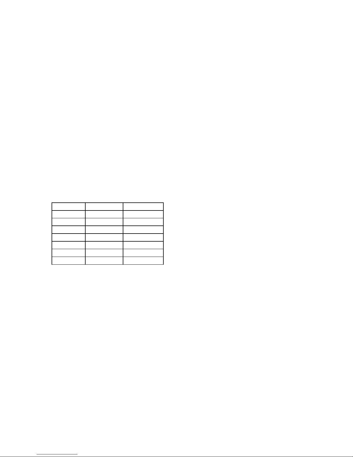
TABLE 2.3: SERIES 205B HIGH VOLTAGE CONNECTORS
MODEL OUTPUT MATING
-01R JDK PDB
-03R JDK PDB
-05R JDK PDB
-10R JJA 405787
-20R JJA 405787
-30R JJA 405787
-50R JJB 405786
Installation and Operating Manual –Series 205B Page 12

SECTION 3 - THEORY OF OPERATION
3.1 FUNCTIONAL DESCRIPTION
The circuit uses a DC to DC converter that converts low voltage DC power to a high voltage DC
outp ut. This output voltage is highly regula ted an d f iltered and can be varied e ither by the front
panel controls or through the REMOTE PROGRAM input on the rear panel. The input to the DC
to DC converter is obtained from internal low voltage power supplies powered by the AC line
input.
An osc illator determines th e freque ncy (appr ox imately 20kH z ) at which all amplific atio n, high
voltage transformation, rectification and filtering occurs. The amplification is a function of a
control vo l tage that perfor ms the fu nctio n of cont rol and regulation. A sample of t he output
voltage is compared against a reference voltage in the sensing circuit. The sensing circuit
generates the control voltage to set and maintain a fixed high voltage output.
3.2 CIRCUIT DESCRIPTION
The input AC line is converted to the B+ (36Vdc) supply and regulated +12Vdc low voltage
power supplies. The B+ supply is a filtered full wave rectifier circuit located on the chassis. The
regulated low voltage power supply circuit (+12Vdc) consists of a rectifier circuit located on T1
and output regulators located on the PCB 100.
The output of the oscillator circuit is amplified in the AGC amplifier. The gain of the AGC
amplifier is a function of the control voltage developed at the output of the error amplifier.
The encapsulated high voltage assembly includes a high voltage power transformer, rectifier or
mult iplier c ircuits, rip ple filter and sensing circuits. These ar e all critic al custom designed a nd
encapsu la t ed components.
A sample of the high voltage DC output is fed to the output voltage sensing circuit and is
compared to a comma n d volta ge. Out put voltage control is obtain e d by var ying the c omman d
voltage fed to the error amplifier. The error amplifier compares the command voltage and the
signal from the output voltage sense circuit. Any difference causes a correction in the gain
control of the AGC amplifier. The comman d voltage is control led by the front p anel controls
when the rear panel program switch is in the LOCAL position.
The reference and reference control and buffer provide a stable +5Vdc to the front panel output
voltage controls.
The current sens ing circ uit mo nitors the outp ut current. The buffered ou tput of this circuit is
employed for both internal and remote current monitoring.
Installation and Operating Manual –Series 205B Page 13

SECTION 4 - MAINTENANCE
4.1 GENERAL
The Series 205B instrument should not require any maintenance. It is designed for reliable,
trouble free operatio n. If any questi on should arise, con tact the Bertan Cu stomer S ervice
Department for assistance or return authorization. It is suggested that the unit be returned to the
factory if servic e should become necess ary.
4.2 CLEANING
Cleaning of the power supply should
power source. A soft cloth moistened with conventional ammonia-based cleaning agents will
suffice for all exposed surfaces. The metal shell of the HV connector should be cleaned with
isopropyl alcohol.
If the supply is operated in a dusty environment, an accumulation of dust/debris may build-up
inside the unit which may cause noisy operation (i.e., “ticking” or minor crackling) in the area of
the HV cabling on the –10R through –50R. The safest way to remove such debris is with
compressed air. Ensure that no dust/debris is left behind in the isulative medium of the HV
output connector after this cleaning operation. Such dust may be removed with a cotton swab
moistened with isop ropyl alcohol.
4.3 CALIBRATION SERVICES
Your BERTAN high voltage power supply is designed to provide many years of reliable service.
For a nominal charge it can b e returned to t h e f actor y f or cal ibration and certif ic atio n to its
original specification. For traceability, a certificate will be issued, identifying the serial number
of the unit calibrated and all test e quipme nt used to perf orm the calibr ation. All measu rements
ar e traceable to th e National Institute of St andar ds and Technology (NIST). Calibration is
guaranteed from 1 year of issuance. Contact the factory at 1-800-966-2776 or your local sales
representative for additional details. For a list of local representatives and other information go to
our website at
www.bertan.com
. You may also email us at
be performed with the supply disconnected from the ac
only
support@bertan.com
.
Installation and Operating Manual –Series 205B Page 14

SECTION 5 - S PEC IFICATIONS
Output Voltage/Current Capability:
MODEL: OUTPUT
:
205B-01R 1kV@30mA
205B-03R 3kV@10mA
205B-05R 5kV@5mA
205B-10R 10kV@2.5mA
205B-20R 20kV@1mA
205B-30R 30kV@500
µ
205B-50R 50kV@300µA
Line Regulation:
0.001% maximum for a ±10% line change.
±
Load Regulation:
0.005% for a NL-FL or FL-NL change.
±
Ripple (max imu m @ max Vout, max Iout ):
MODEL
:
RIPPLE (pk-pk)
:
205B-01R 10mV
205B-03R 30mV
205B-05R 50mV
205B-10R 100mV
205B-20R 300mV
205B-30R 400mV
205B-50R 2V
Temperature Coefficient:
50ppm per °C
Stability (after 30min. warm-up):
0.01% per hour, 0.02% maximum per
8 hours (of maximum rated voltage).
Ambient Temperature Requirements:
Storage: -40°C to +85°C.
Operating: 0° to +50°C.
Humidity:
<90%, non-condensate
Current Capability:
The maximum current rating for each model, as shown in the table to the left, is applicable when
the unit is operated at maximum output voltage. When operated at reduced output voltage levels,
or when operating i n a cur rent limit mode for charging capacitors, the output cu rrent must be
Installation and Operating Manual –Series 205B Page 15

limited to reduced levels. This is required to protec t against excessiv e power d issipa tion of the
driver transistors.
The maximum output current must be linearly derated from maximum output voltage to 30% of
maximum current at zero output voltage. Maximum output current available at any desired
voltage can be calculated by applying the following formula:
Imax = Vset(.7Irated/Vrated)+.3Irated
When operating the power supply as a capacitor charger (i.e., a capacitor is being continuously
discharged then recharged from zero voltage by the power supply) use a charging resistor in
series with the power supply output. The resistance should be equal to the power supply’s
maximum rated output voltage divided by the maximum rated output current.
The above derating factors are safe for all conditions and all models. Consult BERTAN for
sp ecia l cases b efore exceedin g these fa ctors.
Installation and Operating Manual –Series 205B Page 16
 Loading...